EP3944354A1 - Case, secondary battery, battery pack, vehicle, and method for manufacturing secondary battery - Google Patents
Case, secondary battery, battery pack, vehicle, and method for manufacturing secondary battery Download PDFInfo
- Publication number
- EP3944354A1 EP3944354A1 EP20865575.3A EP20865575A EP3944354A1 EP 3944354 A1 EP3944354 A1 EP 3944354A1 EP 20865575 A EP20865575 A EP 20865575A EP 3944354 A1 EP3944354 A1 EP 3944354A1
- Authority
- EP
- European Patent Office
- Prior art keywords
- side wall
- coated region
- case
- insulating coating
- secondary battery
- Prior art date
- Legal status (The legal status is an assumption and is not a legal conclusion. Google has not performed a legal analysis and makes no representation as to the accuracy of the status listed.)
- Granted
Links
Images




Classifications
-
- H—ELECTRICITY
- H01—ELECTRIC ELEMENTS
- H01M—PROCESSES OR MEANS, e.g. BATTERIES, FOR THE DIRECT CONVERSION OF CHEMICAL ENERGY INTO ELECTRICAL ENERGY
- H01M50/00—Constructional details or processes of manufacture of the non-active parts of electrochemical cells other than fuel cells, e.g. hybrid cells
- H01M50/10—Primary casings; Jackets or wrappings
- H01M50/102—Primary casings; Jackets or wrappings characterised by their shape or physical structure
- H01M50/103—Primary casings; Jackets or wrappings characterised by their shape or physical structure prismatic or rectangular
-
- H—ELECTRICITY
- H01—ELECTRIC ELEMENTS
- H01M—PROCESSES OR MEANS, e.g. BATTERIES, FOR THE DIRECT CONVERSION OF CHEMICAL ENERGY INTO ELECTRICAL ENERGY
- H01M10/00—Secondary cells; Manufacture thereof
- H01M10/04—Construction or manufacture in general
-
- H—ELECTRICITY
- H01—ELECTRIC ELEMENTS
- H01M—PROCESSES OR MEANS, e.g. BATTERIES, FOR THE DIRECT CONVERSION OF CHEMICAL ENERGY INTO ELECTRICAL ENERGY
- H01M50/00—Constructional details or processes of manufacture of the non-active parts of electrochemical cells other than fuel cells, e.g. hybrid cells
- H01M50/20—Mountings; Secondary casings or frames; Racks, modules or packs; Suspension devices; Shock absorbers; Transport or carrying devices; Holders
- H01M50/204—Racks, modules or packs for multiple batteries or multiple cells
- H01M50/207—Racks, modules or packs for multiple batteries or multiple cells characterised by their shape
- H01M50/209—Racks, modules or packs for multiple batteries or multiple cells characterised by their shape adapted for prismatic or rectangular cells
-
- H—ELECTRICITY
- H01—ELECTRIC ELEMENTS
- H01M—PROCESSES OR MEANS, e.g. BATTERIES, FOR THE DIRECT CONVERSION OF CHEMICAL ENERGY INTO ELECTRICAL ENERGY
- H01M10/00—Secondary cells; Manufacture thereof
- H01M10/05—Accumulators with non-aqueous electrolyte
- H01M10/052—Li-accumulators
- H01M10/0525—Rocking-chair batteries, i.e. batteries with lithium insertion or intercalation in both electrodes; Lithium-ion batteries
-
- H—ELECTRICITY
- H01—ELECTRIC ELEMENTS
- H01M—PROCESSES OR MEANS, e.g. BATTERIES, FOR THE DIRECT CONVERSION OF CHEMICAL ENERGY INTO ELECTRICAL ENERGY
- H01M50/00—Constructional details or processes of manufacture of the non-active parts of electrochemical cells other than fuel cells, e.g. hybrid cells
- H01M50/10—Primary casings; Jackets or wrappings
- H01M50/116—Primary casings; Jackets or wrappings characterised by the material
- H01M50/117—Inorganic material
- H01M50/119—Metals
-
- H—ELECTRICITY
- H01—ELECTRIC ELEMENTS
- H01M—PROCESSES OR MEANS, e.g. BATTERIES, FOR THE DIRECT CONVERSION OF CHEMICAL ENERGY INTO ELECTRICAL ENERGY
- H01M50/00—Constructional details or processes of manufacture of the non-active parts of electrochemical cells other than fuel cells, e.g. hybrid cells
- H01M50/10—Primary casings; Jackets or wrappings
- H01M50/116—Primary casings; Jackets or wrappings characterised by the material
- H01M50/121—Organic material
-
- H—ELECTRICITY
- H01—ELECTRIC ELEMENTS
- H01M—PROCESSES OR MEANS, e.g. BATTERIES, FOR THE DIRECT CONVERSION OF CHEMICAL ENERGY INTO ELECTRICAL ENERGY
- H01M50/00—Constructional details or processes of manufacture of the non-active parts of electrochemical cells other than fuel cells, e.g. hybrid cells
- H01M50/10—Primary casings; Jackets or wrappings
- H01M50/116—Primary casings; Jackets or wrappings characterised by the material
- H01M50/124—Primary casings; Jackets or wrappings characterised by the material having a layered structure
- H01M50/1245—Primary casings; Jackets or wrappings characterised by the material having a layered structure characterised by the external coating on the casing
-
- H—ELECTRICITY
- H01—ELECTRIC ELEMENTS
- H01M—PROCESSES OR MEANS, e.g. BATTERIES, FOR THE DIRECT CONVERSION OF CHEMICAL ENERGY INTO ELECTRICAL ENERGY
- H01M50/00—Constructional details or processes of manufacture of the non-active parts of electrochemical cells other than fuel cells, e.g. hybrid cells
- H01M50/10—Primary casings; Jackets or wrappings
- H01M50/147—Lids or covers
- H01M50/148—Lids or covers characterised by their shape
- H01M50/15—Lids or covers characterised by their shape for prismatic or rectangular cells
-
- H—ELECTRICITY
- H01—ELECTRIC ELEMENTS
- H01M—PROCESSES OR MEANS, e.g. BATTERIES, FOR THE DIRECT CONVERSION OF CHEMICAL ENERGY INTO ELECTRICAL ENERGY
- H01M50/00—Constructional details or processes of manufacture of the non-active parts of electrochemical cells other than fuel cells, e.g. hybrid cells
- H01M50/10—Primary casings; Jackets or wrappings
- H01M50/147—Lids or covers
- H01M50/155—Lids or covers characterised by the material
- H01M50/157—Inorganic material
- H01M50/159—Metals
-
- H—ELECTRICITY
- H01—ELECTRIC ELEMENTS
- H01M—PROCESSES OR MEANS, e.g. BATTERIES, FOR THE DIRECT CONVERSION OF CHEMICAL ENERGY INTO ELECTRICAL ENERGY
- H01M50/00—Constructional details or processes of manufacture of the non-active parts of electrochemical cells other than fuel cells, e.g. hybrid cells
- H01M50/10—Primary casings; Jackets or wrappings
- H01M50/147—Lids or covers
- H01M50/166—Lids or covers characterised by the methods of assembling casings with lids
- H01M50/169—Lids or covers characterised by the methods of assembling casings with lids by welding, brazing or soldering
-
- H—ELECTRICITY
- H01—ELECTRIC ELEMENTS
- H01M—PROCESSES OR MEANS, e.g. BATTERIES, FOR THE DIRECT CONVERSION OF CHEMICAL ENERGY INTO ELECTRICAL ENERGY
- H01M50/00—Constructional details or processes of manufacture of the non-active parts of electrochemical cells other than fuel cells, e.g. hybrid cells
- H01M50/20—Mountings; Secondary casings or frames; Racks, modules or packs; Suspension devices; Shock absorbers; Transport or carrying devices; Holders
- H01M50/249—Mountings; Secondary casings or frames; Racks, modules or packs; Suspension devices; Shock absorbers; Transport or carrying devices; Holders specially adapted for aircraft or vehicles, e.g. cars or trains
-
- H—ELECTRICITY
- H01—ELECTRIC ELEMENTS
- H01M—PROCESSES OR MEANS, e.g. BATTERIES, FOR THE DIRECT CONVERSION OF CHEMICAL ENERGY INTO ELECTRICAL ENERGY
- H01M50/00—Constructional details or processes of manufacture of the non-active parts of electrochemical cells other than fuel cells, e.g. hybrid cells
- H01M50/20—Mountings; Secondary casings or frames; Racks, modules or packs; Suspension devices; Shock absorbers; Transport or carrying devices; Holders
- H01M50/271—Lids or covers for the racks or secondary casings
-
- H—ELECTRICITY
- H01—ELECTRIC ELEMENTS
- H01M—PROCESSES OR MEANS, e.g. BATTERIES, FOR THE DIRECT CONVERSION OF CHEMICAL ENERGY INTO ELECTRICAL ENERGY
- H01M2220/00—Batteries for particular applications
- H01M2220/20—Batteries in motive systems, e.g. vehicle, ship, plane
-
- Y—GENERAL TAGGING OF NEW TECHNOLOGICAL DEVELOPMENTS; GENERAL TAGGING OF CROSS-SECTIONAL TECHNOLOGIES SPANNING OVER SEVERAL SECTIONS OF THE IPC; TECHNICAL SUBJECTS COVERED BY FORMER USPC CROSS-REFERENCE ART COLLECTIONS [XRACs] AND DIGESTS
- Y02—TECHNOLOGIES OR APPLICATIONS FOR MITIGATION OR ADAPTATION AGAINST CLIMATE CHANGE
- Y02E—REDUCTION OF GREENHOUSE GAS [GHG] EMISSIONS, RELATED TO ENERGY GENERATION, TRANSMISSION OR DISTRIBUTION
- Y02E60/00—Enabling technologies; Technologies with a potential or indirect contribution to GHG emissions mitigation
- Y02E60/10—Energy storage using batteries
-
- Y—GENERAL TAGGING OF NEW TECHNOLOGICAL DEVELOPMENTS; GENERAL TAGGING OF CROSS-SECTIONAL TECHNOLOGIES SPANNING OVER SEVERAL SECTIONS OF THE IPC; TECHNICAL SUBJECTS COVERED BY FORMER USPC CROSS-REFERENCE ART COLLECTIONS [XRACs] AND DIGESTS
- Y02—TECHNOLOGIES OR APPLICATIONS FOR MITIGATION OR ADAPTATION AGAINST CLIMATE CHANGE
- Y02P—CLIMATE CHANGE MITIGATION TECHNOLOGIES IN THE PRODUCTION OR PROCESSING OF GOODS
- Y02P70/00—Climate change mitigation technologies in the production process for final industrial or consumer products
- Y02P70/50—Manufacturing or production processes characterised by the final manufactured product
Definitions
- This application relates to the technical field of energy storage devices, and in particular, to a case, a secondary battery, a battery pack, a vehicle, and a method for manufacturing a secondary battery.
- lithium-ion electronics industry With the rapid development of consumer electronics and electric vehicles, the lithium-ion electronics industry has attracted widespread attention from all walks of life. The requirements for batteries are increasingly strict. As the core part of new energy vehicles, lithium-ion batteries are strictly required to have safety, reliability and stability.
- a lithium-ion battery is composed of an electrode assembly and a metal case accommodating the electrode assembly.
- the case is usually an aluminum case.
- a cover plate is welded to the case by laser to realize the structural connection and sealing of the battery.
- Lithium-ion batteries need to be insulated during use to achieve the safety and reliability of battery module and battery pack.
- the insulation requirements for lithium-ion batteries are generally implemented in the process of assembling batteries into a battery module or battery pack by sticking an insulating film to the surface.
- the insulating film is easily scratched or damaged by external substances, hard particles, etc. during production or operation, resulting in insulation failure to affect the safety performance of batteries.
- the present application provides a case, a secondary battery, a battery pack, a vehicle, and a method for manufacturing a secondary battery, aiming to improve the safety performance of the secondary battery.
- the first aspect of the present application provides a case for a secondary battery, the case including a bottom wall and a side wall, the bottom wall and the side wall defining an accommodating cavity with an opening at one end for accommodating an electrode assembly of the secondary battery; wherein, an outer surface of the side wall includes a coated region coated with an insulating coating, and the coated region extends, in a height direction of the side wall, from a side of the side wall that is close to the bottom wall to a position near an edge of a side of the side wall that is close to the opening, so as to reserve a non-coated region with a preset height on the outer surface of the side wall that is near an edge of the opening.
- the coated region has an area of from 70% to 85%, relative to a total area of the outer surface of the side wall; and/or, the coated region has an extension height of from 70% to 85% in the height direction, relative to a total height of the side wall.
- the non-coated region has an extension height of greater than or equal to 3 mm in the height direction.
- the insulating coating includes: relative to a total weight of the insulating coating, 80-97 wt% of insulating film-forming resin, 3-12 wt% of auxiliary agent, and 0-8 wt% of pigment.
- the pigment is selected from a toner; and/or, the insulating film-forming resin is selected from epoxy resin, polyurethane, acrylic resin, phenolic resin, polyester resin, and combinations thereof; and/or, the auxiliary agent is selected from at least one of a light stabilizer, a heat stabilizer, an antioxidant, a defoamer, a leveling agent, a flame retardant, and a plasticizer.
- the insulating film-forming resin is obtained by photo-curing an acrylic functionalized prepolymer and an acrylic monomer in the presence of a photoinitiator, wherein the acrylic functionalized prepolymer is selected from at least one of a polyester acrylate prepolymer, epoxy acrylate prepolymer, urethane acrylate prepolymer and pure acrylate prepolymer, and the acrylic monomer is selected from at least one of monoalkyl acrylate, diol diacrylate and triol triacrylate; or, the insulating film-forming resin is obtained by curing reaction of epoxy resin, polyurethane, polyester or acrylic resin with a curing agent.
- the insulating coating has a thickness of from 80 ⁇ m to 160 ⁇ m.
- the second aspect of the present application provides a secondary battery, including: the above-mentioned case; an electrode assembly placed in the accommodating cavity; a cover plate covering the opening; and an insulating film covering at least the non-coated region.
- the insulating film includes a bonding segment and a stacking segment successively arranged in the height direction, the bonding segment is bonded to the non-coated region, and the stacking segment extends from the bonding segment to an outer surface of the insulating coating.
- the stacking segment has an extension height of from 1.5 mm to 6 mm in the height direction.
- the third aspect of the present application provides a battery pack, including: a box; and the above-mentioned secondary batteries, the secondary batteries being accommodated in the box.
- the secondary batteries are adhered to an inner wall surface of the box by an adhesive.
- the fourth aspect of the present application provides a vehicle, including the above-mentioned battery pack.
- the fifth aspect of the present application further provides a method for manufacturing a secondary battery, including:
- the case includes a bottom wall, a side wall, and a coated region and a non-coated region on an outer surface of the side wall, and the coated region is coated with an insulating coating.
- the bottom wall and the side wall enclose an accommodating cavity with an opening, and an electrode assembly of a secondary battery can be placed into the accommodating cavity from the opening.
- the coated region extends, in a height direction, from the side of the side wall that is close to the bottom wall to a position near the side of the side wall that is close to the opening, so as to reserve the non-coated region on the outer surface near the edge of the opening.
- the high temperature caused by welding will not affect the stability of the insulating coating on the coated region.
- the outer surface of the side wall is coated with the insulating coating, and the adhesive force between the insulating coating and the side wall is relatively large, which can ensure the flatness and good insulation performance of the outer surface of the side wall. Therefore, during the production and use of the case, the insulating coating can be well bonded to the coated region for a long term, achieving better long-term safety and reliability of the case.
- plural of' means two or more; the orientations or positional relationships indicated by the terms “upper”, “lower”, “left”, “right”, “inner”, “outer”, etc. are only for facilitating description of the present application and simplifying the description, but do not indicate or imply that the pointed apparatuses or elements must have specific orientations or be constructed and operated in specific orientations. Therefore, the terms should not be understood to limit the present application.
- the present application first provides a vehicle, which is provided with a battery pack.
- the battery pack includes a box and a secondary battery accommodated in the box.
- Fig. 1 is a schematic structural diagram of a secondary battery according to an embodiment of the application.
- the secondary battery includes: a case 10 including a bottom wall 100 and a side wall 200, the bottom wall 100 and the side wall 200 defining an accommodating cavity 400 with an opening 300 at one end; an electrode assembly (not shown in the figure) located in the accommodating cavity 400, the electrode assembly being formed by winding a positive electrode plate, a negative electrode plate and a separator, or by stacking a positive electrode plate, a negative electrode plate and a separator, the accommodating cavity 400 being filled with an electrolyte; and a cover plate 500 covering the opening 300 in a sealing manner.
- the case 10 and the cover plate 500 may be connected in various ways.
- the case 10 and the cover plate 500 are connected to each other by welding to ensure the stability of a relative position and the reliability of connection and sealing between the case 10 and the cover plate 500.
- the case 10 of the secondary battery is made of a metal material, such as aluminum or steel.
- the metal case 10 is positively charged under normal circumstances.
- metal particles may fall onto the secondary battery to electrically connect the case 10 of the secondary battery with a negative electrode, causing an external short circuit of the secondary battery to affect the safety performance of the secondary battery. Therefore, insulation protection is required for the secondary battery.
- an outer surface of the cover plate 500 away from the accommodating cavity 400 is provided with a first insulating film 510.
- the arrangement of the first insulating film 510 is not limited.
- the cover plate 500 is further provided with protruding structures such as electrode terminals 520.
- the electrode terminals 520 may include a positive electrode terminal and a negative electrode terminal.
- the first insulating film 510 is provided with through holes from which the electrode terminals 520 extend out.
- Gaps are prevented between the first insulating film 510 and the cover plate 500 due to the protruding structures, the contact area between the cover plate 500 and the first insulating film 510 is increased, and the stability of a relative position and the reliability of connection between the cover plate 500 and the first insulating film 510 are thus improved.
- the first insulating film 510 may be configured in various ways.
- the first insulating film 510 includes one or more of polyethylene terephthalate, polyimide, polycarbonate, polyethylene, polyvinylidene fluoride, and polytetrafluoroethylene.
- the case 10 may be configured in various ways.
- the case 10 may be covered with an insulating film.
- an outer surface of the side wall 200 includes a coated region coated with an insulating coating 210, and the coated region extends, in a height direction (Z direction in Fig. 1 ) of the side wall 200, from the side of the side wall 200 that is close to the bottom wall 100 to a position near an edge of the side of the side wall 200 that is close to the opening 300, so as to reserve a non-coated region with a preset height on the outer surface of the side wall 200 that is near the edge of the opening 300.
- the coated region does not extend to the edge of the opening 300 in the height direction, the insulating coating 200 does not completely cover the outer surface of the side wall 200, and the coated region is close to the edge of the opening 300 in the height direction but separated from the edge of the opening 300 by a predetermined distance, defining the non-coated region on the outer surface of the side wall 200, which is not covered by the insulating coating 210. That is, the outer surface of the side wall 200 includes a coated region and a non-coated region successively arranged in the height direction, the coated region is closer to the bottom wall 100 than the non-coated region, and the non-coated region is closer to the opening 300 than the coated region.
- the outer surface of the side wall 200 refers to the surface of the side wall 200 away from the accommodating cavity 400.
- the side of the side wall 200 that is close to the bottom wall 100 is specifically a junction between the side wall 200 and the bottom wall 100.
- the insulating coating 210 may be configured in various ways, and the insulating coating 210 is usually formed by applying an organic coating to the coated region.
- the coating is sensitive to temperature. If the ambient temperature of the insulating coating 210 is too high and higher than the melting point of the coating, the insulating coating 210 is likely to melt, which will affect the stability and insulation protection performance of the insulating coating 210.
- the coated region extends, in the height direction, from the side of the side wall 200 that is close to the bottom wall 100 to a position near the side of the side wall 200 that is close to the opening 300, so as to reserve the non-coated region on the outer surface of the side wall 200 that is near the edge of the opening 300.
- the cover plate 500 of the secondary battery is welded to the case 10 at the opening 300, the high temperature caused by welding will not affect the stability of the insulating coating 210 on the coated region.
- the outer surface of the side wall 200 is coated with an insulating coating 210, the adhesion of the insulating coating 210 is relatively strong, and the adhesive force between the insulating coating 210 and the side wall 200 is relatively large, which can ensure the flatness of the outer surface of the side wall 200 and good insulation performance. Therefore, during the production and use of the case 10, the insulating coating 210 can be well bonded to the coated region for a long term, achieving a better long-term safety and reliability of the case 10.
- the outer surface of the bottom wall 100 away from the accommodating cavity 400 is also coated with the insulating coating 210.
- the insulation performance between the bottom wall 100 of the secondary battery and a bottom plate of the box can be ensured.
- the insulating coating 210 coated on the outer surface of the side wall 200 and the insulating coating 210 coated on the outer surface of the bottom wall 100 are configured integrally.
- the secondary battery When the outer surface of the case 10 of the secondary battery is coated with the insulating coating 210, the secondary battery is adhered to an inner wall surface of the box by an adhesive. Since the outer surface of the case 10 is provided with the insulating coating 210, the relative position between the insulating coating 210 and the bottom wall 100 or the side wall 200 is more stable. When the secondary battery is adhered to the inner wall surface of the box, the stability of the relative position between the secondary battery and the case will not be affected due to the relative movement of the insulating coating 210 with respect to the case 10.
- the inner wall surface of the box is not limited.
- the box includes a bottom plate, a plurality of side plates connected to a peripheral side of the bottom plate, an accommodating space enclosed by the bottom plate and the plurality of side plates, a box opening communicated with the accommodating space, and an upper cover covering the box opening, the upper cover and the bottom plate being disposed oppositely in the height direction of the box.
- the inner wall surface of the box may be the surface of the bottom plate facing the accommodating space, or the surface of the side plates or the upper cover facing the accommodating space.
- the inner wall surface of the box is the surface of the bottom plate facing the accommodating space, and the secondary battery is adhered to the bottom plate by an adhesive, so that the secondary battery is fixed to the bottom plate of the box.
- the area and shape of the coated region are not limited here.
- the coated region has an area of from 70% to 85%, relative to a total area of the outer surface of the side wall 200. Further, the coated region has an area of 80%, relative to a total area of the outer surface of the side wall 200.
- the case 10 is usually prismatic or cylindrical.
- the coated region has an extension height of from 70% to 85% in the height direction, relative to a total height of the side wall 200. It can also ensure that the insulating coating 210 occupies a large area on the outer surface of the side wall 200, and ensure good adhesion performance between the insulating coating 210 and the side wall 200.
- the extension height m of the non-coated region in the height direction is greater than or equal to 3 mm.
- the high temperature region caused by welding is limited.
- the height m of the non-coated region near the opening 300 is greater than or equal to 3 mm, which can effectively ensure that the high temperature produced during the welding will not be spread to the coated region to affect the stability of the insulating coating 210.
- the edge of the coated region that is close to the opening 300 and the edge of the side wall 200 that is close to the opening 300 are disposed in parallel.
- the non-coated region has the same height at different positions in the circumferential direction of the case 10, and the stability of the insulating coating 210 will not be affected on the circumferential side of the opening 300 during the welding of the cover plate 500 and the case 10.
- the insulating coating 210 needs to have a certain thickness.
- the insulating coating 210 has a thickness of from 80 ⁇ m to 160 ⁇ m. Further, the insulating coating 210 has a thickness of from 100 ⁇ m to 140 ⁇ m. When the thickness of the insulating coating 210 is within said thickness range, it can not only ensure that the insulation performance of the insulating coating 210 meets the requirements, but also can prevent too large size of the case 10 due to excessive thickness of the insulating coating 210. The excessive thickness of the insulating coating 210 will also lead to waste of the coating for the insulating coating 210 and reduce the energy density of the secondary battery.
- the thickness of the insulating coating 210 refers to a distance between the outer surface of the insulating coating 210 away from the accommodating cavity 400 and the outer surface of the side wall 200. There may be a certain variation in the thickness of the insulating coating 210 everywhere in the coated region. The thickness of the insulating coating 210 may be an average thickness of the insulating coating 210 everywhere in the coated region, or the thickness of the insulating coating 210 may be a minimum thickness of the insulating coating 210 everywhere in the coated region.
- the insulating coating 210 is formed by applying an organic coating to the coated region.
- the insulating coating 210 includes: relative to a total weight of the insulating coating, 80-97 wt% of insulating film-forming resin, 3-12 wt% of auxiliary agent, and 0-8 wt% of pigment.
- the insulating coating 210 includes 1-8 wt% of pigment.
- the pigment may be selected to have a designated color, such as blue, yellow, or red color.
- the pigment is added to the insulating coating 210.
- the pigment is selected from toners.
- the toners include blue powder and titanium dioxide.
- the blue powder may be, for example, phthalocyanine blue powder.
- the ratio of the blue powder to the titanium dioxide is not limited here.
- the ratio of the blue powder to the titanium dioxide is 1: 10.
- pigment powders in the pigment have a particle size of less than or equal to 25 ⁇ m. This can prevent the too large particle size of the pigment powders from affecting the performance of the insulating coating 210.
- the insulating film-forming resin may be configured in various ways.
- the insulating film-forming resin is selected from epoxy resin, polyurethane resin, acrylic resin, phenolic resin, polyester resin, and combinations thereof. It can not only ensure that the insulating coating 210 has good insulation performance, but also can ensure that the insulating coating 210 has good adhesion, resistivity, etc.
- the auxiliary agent may be configured in various ways.
- the auxiliary agent is selected from at least one of a light stabilizer, a heat stabilizer, an antioxidant, a defoamer, a leveling agent, a flame retardant, and a plasticizer. This is beneficial to the curing and molding of the insulating coating 210 later.
- the insulating coating 210 may be photo-cured or thermo-cured.
- the insulating film-forming resin is obtained by photo-curing an acrylic functionalized prepolymer and an acrylic monomer in the presence of a photoinitiator, wherein the acrylic functionalized prepolymer is selected from at least one of a polyester acrylate prepolymer, epoxy acrylate prepolymer, urethane acrylate prepolymer and pure acrylate prepolymer, and the acrylic monomer is selected from at least one of monoalkyl acrylate, diol diacrylate and triol triacrylate.
- the insulating film-forming resin is obtained by curing reaction of epoxy resin, polyurethane, polyester or acrylic resin with a curing agent.
- the insulating coating 210 when the insulating coating 210 is formed by photo-curing, includes, for example, 5-8 wt% of pigment, 60-80 wt% of prepolymer, 10-30 wt% of monomer, 2-10 wt% of photoinitiator, and 1-3 wt% of auxiliary agent.
- the prepolymer includes, for example, a polyester acrylate prepolymer, which has fast curing speed, high gloss and good adhesion; or the prepolymer includes an epoxy acrylate prepolymer, which has good chemical resistance, heat resistance, fullness and adhesion; or, the prepolymer includes a urethane acrylate prepolymer, which has the advantages of low energy, low shrinkage, good leveling, and improved toughness; or the prepolymer includes a pure acrylate prepolymer, which has the advantages of low viscosity and good leveling appearance.
- the monomer is an organic small molecule including a polymerizable functional group, is easy to dissolve and dilute, and can adjust the viscosity of the system.
- the monomer includes, for example, alkyl acrylate, which has the characteristics of low viscosity, strong diluting ability, low photo-curing speed, low cross-linking density, low volume shrinkage, etc.
- the monomer includes dipropylene glycol diacrylate, which can effectively improve the adhesion of the insulating coating.
- the monomer includes trihydroxymethylpropane triacrylate, which has the characteristics of fast photo-curing speed, high cross-linking density, high film hardness and brittleness, good resistance, large molecular weight, high viscosity, etc.
- the photoinitiator After the photoinitiator absorbs light energy, it can jump to an excited singlet state, and then jump to an excited triplet state through intersystem crossing, and its molecular structure is unstable in the excited singlet or triplet state.
- the weak bond in the photoinitiator undergoes homolysis to generate active free radicals, which initiate the polymerization and cross-linking of oligomers and monomers.
- An absorption spectrum of the photoinitiator matches an emission spectrum of a light source.
- the photoinitiator may be, for example, an ITX photoinitiator or TPO photoinitiator suitable for colored systems.
- the photoinitiator is a 907 photoinitiator or 1173 photoinitiator which can be dried quickly.
- the auxiliary agent may be, for example, a chain transfer agent, a light or heat stabilizer, a plasticizer, an oxygen inhibitor, or a free radical trapping agent.
- the insulating coating 210 when the insulating coating 210 is formed by thermo-curing, includes, for example, 2-3 wt% of pigment, 40-55 wt% of matrix resin, 30-50 wt% of curing agent, and 1-15 wt% of auxiliary agent.
- the matrix resin may include, for example, epoxy resin, which has the characteristics of strong adhesion, strong mechanical properties, low curing shrinkage, good chemical stability, etc.
- the curing agent may include, for example, phenolic resin, which has the characteristics of good wear resistance, high strength, good corrosion resistance, etc.
- the curing agent may also include dicyandiamide and the like.
- the auxiliary agent may include, for example, a defoamer, a leveling agent, a flame retardant, a plasticizer, etc.
- the secondary battery further includes a second insulating film 220, which covers at least the non-coated region to ensure insulation of the non-coated region.
- the second insulating film 220 may be configured in various ways.
- the second insulating film 220 covers only the non-coated region.
- the second insulating film 220 includes a bonding segment 221 and a stacking segment 222 successively arranged in the height direction, the bonding segment 221 is bonded to the non-coated region, and the stacking segment 222 extends from the bonding segment 221 to the outer surface of the insulating coating 210.
- the second insulating film 220 and the insulating coating 210 can be stacked on each other through the stacking segment 222, which prevents a gap between the second insulating film 220 and the insulating coating 210 affecting the insulation performance of the outer surface of the case 10.
- the stacking height of the second insulating film 220 and the insulating coating 210 is not limited, that is, the extension height of the stacking segment 222 in the height direction is not limited.
- the stacking segment 222 has an extension height of from 1.5 mm to 6 mm in the height direction.
- the stacking segment 222 has an extension height of from 3 mm to 5 mm in the height direction.
- the second insulating film 220 has a thickness of from 100 ⁇ m to 120 ⁇ m.
- the second insulating film 220 has a thickness of 110 ⁇ m.
- the second insulating film 220 and the first insulating film 510 are disposed integrally, which can improve the assembly efficiency of the secondary battery.
- the material of the second insulating film 220 is the same as that of the first insulating film 510, so details are not described herein again.
- the second aspect of the present application further provides a method for manufacturing a secondary battery, including:
- Step S001 providing a case.
- the case may be the case in any of the above embodiments.
- Step S002 placing an electrode assembly into the accommodating cavity from the opening.
- Step S003 covering the opening by a cover plate, and welding the cover plate and the side wall to each other.
- Step S004 bonding an insulating film to the outside of the side wall, the insulating film covering at least the non-coated region.
- step S003 that is, before the cover plate 500 and the case 10 are welded, the electrode assembly is placed and the cover plate 500 is closed, the insulating coating 210 is coated because the case at this time is relatively light and simple in structure, facilitating the application of the insulating coating 210.
- the non-coated region can prevent the high temperature caused by welding from affecting the stability of the insulating coating 210.
- step S004 the insulation performance of the outer surface of the side wall 200 can be further improved, and safety accidents caused by electrification of the non-coated region can be prevented.
- step S001 includes:
- Step S011 providing a case body.
- Fig. 5 shows a case body according to an embodiment of the present application.
- the case body includes a side wall 200, a bottom wall 100, an accommodating cavity 400, and an opening 300.
- Step S012 cleaning the case body.
- the cleaning method includes but is not limited to: ethanol cleaning, acetone cleaning, butanone cleaning, isoacetone cleaning, laser cleaning, plasma cleaning, etc. After cleaning, the case body has a surface energy of greater than 36 N/m.
- the outer surface of the side wall 200 of the case body is divided into a coated region and a non-coated region.
- the boundary between the coated region and the non-coated region is shown by a dotted line in Fig. 6 . It can be understood that the dotted line does not constitute a limitation on the structure of the case body.
- the portion with an extension size m in the height direction is the non-coated region
- the portion with an extension size h in the height direction is the coated region
- the non-coated region is located on the side of the coated region that is close to the opening 300.
- Step S013 coating the coated region with the insulating coating 210 to form the case as described in any of the above embodiments.
- the coated region of the side wall 200 is coated with the insulating coating 210.
- the electrode assembly is placed in the case according to step S002.
- the opening 300 is covered by the cover plate 500 in step S003.
- the cover plate 500 and the side wall 200 are welded to each other in the non-coated region, the second insulating film 220 is bonded to the non-coated region of the side wall 200 so that the second insulating film 220 covers at least part of the insulating coating 210, and the first insulating film 510 is bonded to the top of the cover plate 500 to form the secondary battery described in any of the above embodiments.
- the coated region is coated with the insulating coating by, but not limited to, an adhesive.
Landscapes
- Chemical & Material Sciences (AREA)
- Chemical Kinetics & Catalysis (AREA)
- Electrochemistry (AREA)
- General Chemical & Material Sciences (AREA)
- Engineering & Computer Science (AREA)
- Inorganic Chemistry (AREA)
- Manufacturing & Machinery (AREA)
- Aviation & Aerospace Engineering (AREA)
- Materials Engineering (AREA)
- Sealing Battery Cases Or Jackets (AREA)
Abstract
Description
- This application claims priority to
Chinese Patent Application No. 201910884725.4 entitled "Case, Secondary Battery, Battery Pack, Vehicle, and Method for Manufacturing Secondary Battery" and filed on September 19, 2019 - This application relates to the technical field of energy storage devices, and in particular, to a case, a secondary battery, a battery pack, a vehicle, and a method for manufacturing a secondary battery.
- With the rapid development of consumer electronics and electric vehicles, the lithium-ion electronics industry has attracted widespread attention from all walks of life. The requirements for batteries are increasingly strict. As the core part of new energy vehicles, lithium-ion batteries are strictly required to have safety, reliability and stability.
- A lithium-ion battery is composed of an electrode assembly and a metal case accommodating the electrode assembly. The case is usually an aluminum case. After the electrode assembly is assembled into the case, a cover plate is welded to the case by laser to realize the structural connection and sealing of the battery. Lithium-ion batteries need to be insulated during use to achieve the safety and reliability of battery module and battery pack. At present, the insulation requirements for lithium-ion batteries are generally implemented in the process of assembling batteries into a battery module or battery pack by sticking an insulating film to the surface. However, the insulating film is easily scratched or damaged by external substances, hard particles, etc. during production or operation, resulting in insulation failure to affect the safety performance of batteries.
- Therefore, a new case, secondary battery, battery pack, vehicle, and method for manufacturing a secondary battery are urgently needed.
- The present application provides a case, a secondary battery, a battery pack, a vehicle, and a method for manufacturing a secondary battery, aiming to improve the safety performance of the secondary battery.
- The first aspect of the present application provides a case for a secondary battery, the case including a bottom wall and a side wall, the bottom wall and the side wall defining an accommodating cavity with an opening at one end for accommodating an electrode assembly of the secondary battery; wherein, an outer surface of the side wall includes a coated region coated with an insulating coating, and the coated region extends, in a height direction of the side wall, from a side of the side wall that is close to the bottom wall to a position near an edge of a side of the side wall that is close to the opening, so as to reserve a non-coated region with a preset height on the outer surface of the side wall that is near an edge of the opening.
- Optionally, the coated region has an area of from 70% to 85%, relative to a total area of the outer surface of the side wall; and/or, the coated region has an extension height of from 70% to 85% in the height direction, relative to a total height of the side wall.
- Optionally, the non-coated region has an extension height of greater than or equal to 3 mm in the height direction.
- Optionally, the insulating coating includes: relative to a total weight of the insulating coating, 80-97 wt% of insulating film-forming resin, 3-12 wt% of auxiliary agent, and 0-8 wt% of pigment.
- Optionally, the pigment is selected from a toner; and/or, the insulating film-forming resin is selected from epoxy resin, polyurethane, acrylic resin, phenolic resin, polyester resin, and combinations thereof; and/or, the auxiliary agent is selected from at least one of a light stabilizer, a heat stabilizer, an antioxidant, a defoamer, a leveling agent, a flame retardant, and a plasticizer.
- Optionally, the insulating film-forming resin is obtained by photo-curing an acrylic functionalized prepolymer and an acrylic monomer in the presence of a photoinitiator, wherein the acrylic functionalized prepolymer is selected from at least one of a polyester acrylate prepolymer, epoxy acrylate prepolymer, urethane acrylate prepolymer and pure acrylate prepolymer, and the acrylic monomer is selected from at least one of monoalkyl acrylate, diol diacrylate and triol triacrylate; or, the insulating film-forming resin is obtained by curing reaction of epoxy resin, polyurethane, polyester or acrylic resin with a curing agent.
- Optionally, the insulating coating has a thickness of from 80 µm to 160 µm.
- The second aspect of the present application provides a secondary battery, including: the above-mentioned case; an electrode assembly placed in the accommodating cavity; a cover plate covering the opening; and an insulating film covering at least the non-coated region.
- Optionally, the insulating film includes a bonding segment and a stacking segment successively arranged in the height direction, the bonding segment is bonded to the non-coated region, and the stacking segment extends from the bonding segment to an outer surface of the insulating coating.
- Optionally, the stacking segment has an extension height of from 1.5 mm to 6 mm in the height direction.
- The third aspect of the present application provides a battery pack, including: a box; and the above-mentioned secondary batteries, the secondary batteries being accommodated in the box.
- Optionally, the secondary batteries are adhered to an inner wall surface of the box by an adhesive.
- The fourth aspect of the present application provides a vehicle, including the above-mentioned battery pack.
- The fifth aspect of the present application further provides a method for manufacturing a secondary battery, including:
- providing the above-mentioned case;
- placing an electrode assembly into the accommodating cavity from the opening;
- covering the opening by a cover plate, and welding the cover plate and the side wall to each other; and
- bonding an insulating film to the outside of the side wall, the insulating film covering at least the non-coated region.
- In the case according to the present application, the case includes a bottom wall, a side wall, and a coated region and a non-coated region on an outer surface of the side wall, and the coated region is coated with an insulating coating. The bottom wall and the side wall enclose an accommodating cavity with an opening, and an electrode assembly of a secondary battery can be placed into the accommodating cavity from the opening. The coated region extends, in a height direction, from the side of the side wall that is close to the bottom wall to a position near the side of the side wall that is close to the opening, so as to reserve the non-coated region on the outer surface near the edge of the opening. As such, when a cover plate of the secondary battery is welded to the case at the opening, the high temperature caused by welding will not affect the stability of the insulating coating on the coated region. The outer surface of the side wall is coated with the insulating coating, and the adhesive force between the insulating coating and the side wall is relatively large, which can ensure the flatness and good insulation performance of the outer surface of the side wall. Therefore, during the production and use of the case, the insulating coating can be well bonded to the coated region for a long term, achieving better long-term safety and reliability of the case.
- The features, advantages, and technical effects of exemplary embodiments of the present application will be described below with reference to the accompanying drawings, and the accompanying drawings are not drawn according to actual scale.
-
Fig. 1 is a schematic structural diagram of a secondary battery according to an embodiment of the first aspect of the present application; -
Fig. 2 is a top view of the secondary battery according to an embodiment of the first aspect of the present application; -
Fig. 3 is a partial cross-sectional view along A-A inFig. 2 ; -
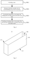
Fig. 4 is a schematic flowchart of a method for manufacturing a secondary battery according to an embodiment of the fifth aspect of the present application; -
Fig. 5 is a schematic structural diagram of a case provided in the method for manufacturing a secondary battery according to an embodiment of the fifth aspect of the present application; -
Fig. 6 is a schematic structural diagram of a case including a coated region and a non-coated region provided in the method for manufacturing a secondary battery according to an embodiment of the fifth aspect of the present application; -
Fig. 7 is a schematic structural diagram of a case with an insulating coating provided in the method for manufacturing a secondary battery according to an embodiment of the fifth aspect of the present application; and -
Fig. 8 is a schematic structural diagram of a secondary battery with a cover plate welded provided in the method for manufacturing a secondary battery according to an embodiment of the fifth aspect of the present application. - 10, case; 100, bottom wall; 200, side wall; 210, insulating coating; 220, second insulating film; 221, bonding segment; 222, stacking segment; 300, opening; 400, accommodating cavity; 500, cover plate; 510, first insulating film; 520, electrode terminal; Z, height direction.
- The features and exemplary embodiments of various aspects of the present application will be described in detail below. In the following detailed description, many specific details are given in order to provide a comprehensive understanding of the present application. However, it will be obvious to those skilled in the art that the present application may be implemented without some of these specific details. The following description of the embodiments is only to provide a better understanding of the present application by showing examples of the present application. In the drawings and the following description, at least part of the well-known structures and technologies are not shown in order to avoid unnecessary blurring of the present application; and, for clarity, the sizes of some structures may be exaggerated. Furthermore, the features, structures or characteristics described hereinafter may be combined in any suitable manner in one or more embodiments.
- In the description of the present application, it should be noted that, unless otherwise specified, "plurality of' means two or more; the orientations or positional relationships indicated by the terms "upper", "lower", "left", "right", "inner", "outer", etc. are only for facilitating description of the present application and simplifying the description, but do not indicate or imply that the pointed apparatuses or elements must have specific orientations or be constructed and operated in specific orientations. Therefore, the terms should not be understood to limit the present application.
- The orientation terms appearing in the following description all indicate directions shown in the drawings, and are not intended to limit the specific structures of the embodiments of the present application. In the description of the present application, it should also be noted that, unless otherwise clearly specified and defined, the terms "mounted" and "connected" should be understood broadly; for example, the term "connected" may refer to two components that are fixedly connected, detachably connected, integrally connected, directly connected, or indirectly connected. Those of ordinary skill in the art could understand the specific meanings of the above terms in the present application depending on specific circumstances.
- In order to better understand the present application, the case, secondary battery, battery pack, vehicle, and method for manufacturing a secondary battery according to the embodiments of the present application will be described in detail below in conjunction with
Figs. 1 to 8 . - The present application first provides a vehicle, which is provided with a battery pack. The battery pack includes a box and a secondary battery accommodated in the box.
-
Fig. 1 is a schematic structural diagram of a secondary battery according to an embodiment of the application. The secondary battery includes: acase 10 including abottom wall 100 and aside wall 200, thebottom wall 100 and theside wall 200 defining anaccommodating cavity 400 with anopening 300 at one end; an electrode assembly (not shown in the figure) located in theaccommodating cavity 400, the electrode assembly being formed by winding a positive electrode plate, a negative electrode plate and a separator, or by stacking a positive electrode plate, a negative electrode plate and a separator, theaccommodating cavity 400 being filled with an electrolyte; and acover plate 500 covering theopening 300 in a sealing manner. - The
case 10 and thecover plate 500 may be connected in various ways. Optionally, thecase 10 and thecover plate 500 are connected to each other by welding to ensure the stability of a relative position and the reliability of connection and sealing between thecase 10 and thecover plate 500. - In some optional embodiments, the
case 10 of the secondary battery is made of a metal material, such as aluminum or steel. In order to prevent electrochemical corrosion of themetal case 10, themetal case 10 is positively charged under normal circumstances. When the secondary battery is assembled into a battery module or a battery pack, metal particles may fall onto the secondary battery to electrically connect thecase 10 of the secondary battery with a negative electrode, causing an external short circuit of the secondary battery to affect the safety performance of the secondary battery. Therefore, insulation protection is required for the secondary battery. - In some optional embodiments, an outer surface of the
cover plate 500 away from theaccommodating cavity 400 is provided with a firstinsulating film 510. The arrangement of the first insulatingfilm 510 is not limited. For example, thecover plate 500 is further provided with protruding structures such aselectrode terminals 520. Theelectrode terminals 520 may include a positive electrode terminal and a negative electrode terminal. The firstinsulating film 510 is provided with through holes from which theelectrode terminals 520 extend out. Gaps are prevented between the first insulatingfilm 510 and thecover plate 500 due to the protruding structures, the contact area between thecover plate 500 and the first insulatingfilm 510 is increased, and the stability of a relative position and the reliability of connection between thecover plate 500 and the first insulatingfilm 510 are thus improved. - The first
insulating film 510 may be configured in various ways. For example, the first insulatingfilm 510 includes one or more of polyethylene terephthalate, polyimide, polycarbonate, polyethylene, polyvinylidene fluoride, and polytetrafluoroethylene. - In order to ensure the insulation performance of the
case 10 of the secondary battery, thecase 10 may be configured in various ways. For example, thecase 10 may be covered with an insulating film. - In other optional embodiments, an outer surface of the
side wall 200 includes a coated region coated with an insulatingcoating 210, and the coated region extends, in a height direction (Z direction inFig. 1 ) of theside wall 200, from the side of theside wall 200 that is close to thebottom wall 100 to a position near an edge of the side of theside wall 200 that is close to theopening 300, so as to reserve a non-coated region with a preset height on the outer surface of theside wall 200 that is near the edge of theopening 300. The coated region does not extend to the edge of theopening 300 in the height direction, the insulatingcoating 200 does not completely cover the outer surface of theside wall 200, and the coated region is close to the edge of theopening 300 in the height direction but separated from the edge of theopening 300 by a predetermined distance, defining the non-coated region on the outer surface of theside wall 200, which is not covered by the insulatingcoating 210. That is, the outer surface of theside wall 200 includes a coated region and a non-coated region successively arranged in the height direction, the coated region is closer to thebottom wall 100 than the non-coated region, and the non-coated region is closer to theopening 300 than the coated region. The outer surface of theside wall 200 refers to the surface of theside wall 200 away from theaccommodating cavity 400. In some optional embodiments, the side of theside wall 200 that is close to thebottom wall 100 is specifically a junction between theside wall 200 and thebottom wall 100. - The insulating
coating 210 may be configured in various ways, and the insulatingcoating 210 is usually formed by applying an organic coating to the coated region. The coating is sensitive to temperature. If the ambient temperature of the insulatingcoating 210 is too high and higher than the melting point of the coating, the insulatingcoating 210 is likely to melt, which will affect the stability and insulation protection performance of the insulatingcoating 210. - In the
case 10 of the embodiment of the present application, the coated region extends, in the height direction, from the side of theside wall 200 that is close to thebottom wall 100 to a position near the side of theside wall 200 that is close to theopening 300, so as to reserve the non-coated region on the outer surface of theside wall 200 that is near the edge of theopening 300. As such, when thecover plate 500 of the secondary battery is welded to thecase 10 at theopening 300, the high temperature caused by welding will not affect the stability of the insulatingcoating 210 on the coated region. The outer surface of theside wall 200 is coated with an insulatingcoating 210, the adhesion of the insulatingcoating 210 is relatively strong, and the adhesive force between the insulatingcoating 210 and theside wall 200 is relatively large, which can ensure the flatness of the outer surface of theside wall 200 and good insulation performance. Therefore, during the production and use of thecase 10, the insulatingcoating 210 can be well bonded to the coated region for a long term, achieving a better long-term safety and reliability of thecase 10. - Further, in other optional embodiments, the outer surface of the
bottom wall 100 away from theaccommodating cavity 400 is also coated with the insulatingcoating 210. As such, when the secondary battery is disposed in the box of the battery pack, the insulation performance between thebottom wall 100 of the secondary battery and a bottom plate of the box can be ensured. Further, the insulatingcoating 210 coated on the outer surface of theside wall 200 and the insulatingcoating 210 coated on the outer surface of thebottom wall 100 are configured integrally. - When the outer surface of the
case 10 of the secondary battery is coated with the insulatingcoating 210, the secondary battery is adhered to an inner wall surface of the box by an adhesive. Since the outer surface of thecase 10 is provided with the insulatingcoating 210, the relative position between the insulatingcoating 210 and thebottom wall 100 or theside wall 200 is more stable. When the secondary battery is adhered to the inner wall surface of the box, the stability of the relative position between the secondary battery and the case will not be affected due to the relative movement of the insulatingcoating 210 with respect to thecase 10. - The inner wall surface of the box is not limited. In some optional embodiments, the box includes a bottom plate, a plurality of side plates connected to a peripheral side of the bottom plate, an accommodating space enclosed by the bottom plate and the plurality of side plates, a box opening communicated with the accommodating space, and an upper cover covering the box opening, the upper cover and the bottom plate being disposed oppositely in the height direction of the box. The inner wall surface of the box may be the surface of the bottom plate facing the accommodating space, or the surface of the side plates or the upper cover facing the accommodating space.
- Optionally, the inner wall surface of the box is the surface of the bottom plate facing the accommodating space, and the secondary battery is adhered to the bottom plate by an adhesive, so that the secondary battery is fixed to the bottom plate of the box.
- The area and shape of the coated region are not limited here. In order to ensure good insulation performance on the outer surface of the
case 10 and good adhesion between the insulatingcoating 210 and thecase 10, the coated region has an area of from 70% to 85%, relative to a total area of the outer surface of theside wall 200. Further, the coated region has an area of 80%, relative to a total area of the outer surface of theside wall 200. - The
case 10 is usually prismatic or cylindrical. In order to ensure good adhesion between the insulatingcoating 210 and thecase 10, an extension height h of the coated region in the height direction and a total height H of theside wall 200 should satisfy the following relation:
- That is, the coated region has an extension height of from 70% to 85% in the height direction, relative to a total height of the
side wall 200. It can also ensure that the insulatingcoating 210 occupies a large area on the outer surface of theside wall 200, and ensure good adhesion performance between the insulatingcoating 210 and theside wall 200. - In other optional embodiments, in order to ensure that the insulating
coating 210 is not affected during the welding of thecover plate 500 and thecase 10, the extension height m of the non-coated region in the height direction is greater than or equal to 3 mm. When thecover plate 500 is welded to theopening 300 of thecase 10, the high temperature region caused by welding is limited. The height m of the non-coated region near theopening 300 is greater than or equal to 3 mm, which can effectively ensure that the high temperature produced during the welding will not be spread to the coated region to affect the stability of the insulatingcoating 210. - In some optional embodiments, the edge of the coated region that is close to the
opening 300 and the edge of theside wall 200 that is close to theopening 300 are disposed in parallel. As such, the non-coated region has the same height at different positions in the circumferential direction of thecase 10, and the stability of the insulatingcoating 210 will not be affected on the circumferential side of theopening 300 during the welding of thecover plate 500 and thecase 10. - In order to ensure good insulation performance, the insulating
coating 210 needs to have a certain thickness. In some optional embodiments, the insulatingcoating 210 has a thickness of from 80 µm to 160 µm. Further, the insulatingcoating 210 has a thickness of from 100 µm to 140 µm. When the thickness of the insulatingcoating 210 is within said thickness range, it can not only ensure that the insulation performance of the insulatingcoating 210 meets the requirements, but also can prevent too large size of thecase 10 due to excessive thickness of the insulatingcoating 210. The excessive thickness of the insulatingcoating 210 will also lead to waste of the coating for the insulatingcoating 210 and reduce the energy density of the secondary battery. - The thickness of the insulating
coating 210 refers to a distance between the outer surface of the insulatingcoating 210 away from theaccommodating cavity 400 and the outer surface of theside wall 200. There may be a certain variation in the thickness of the insulatingcoating 210 everywhere in the coated region. The thickness of the insulatingcoating 210 may be an average thickness of the insulatingcoating 210 everywhere in the coated region, or the thickness of the insulatingcoating 210 may be a minimum thickness of the insulatingcoating 210 everywhere in the coated region. - As described above, in order to improve the adhesion of the insulating
coating 210, the insulatingcoating 210 is formed by applying an organic coating to the coated region. Optionally, the insulatingcoating 210 includes: relative to a total weight of the insulating coating, 80-97 wt% of insulating film-forming resin, 3-12 wt% of auxiliary agent, and 0-8 wt% of pigment. - Optionally, the insulating
coating 210 includes 1-8 wt% of pigment. The pigment may be selected to have a designated color, such as blue, yellow, or red color. The pigment is added to the insulatingcoating 210. When the insulatingcoating 210 is coated on the outer surface of theside wall 200, it is easy to distinguish one from another, so that the user can determine the coated area of the insulatingcoating 210 according to the color of the insulatingcoating 210. - In some optional embodiments, the pigment is selected from toners. For example, the toners include blue powder and titanium dioxide. The blue powder may be, for example, phthalocyanine blue powder. The ratio of the blue powder to the titanium dioxide is not limited here. For example, the ratio of the blue powder to the titanium dioxide is 1: 10.
- In other optional embodiments, pigment powders in the pigment have a particle size of less than or equal to 25 µm. This can prevent the too large particle size of the pigment powders from affecting the performance of the insulating
coating 210. - The insulating film-forming resin may be configured in various ways. For example, the insulating film-forming resin is selected from epoxy resin, polyurethane resin, acrylic resin, phenolic resin, polyester resin, and combinations thereof. It can not only ensure that the insulating
coating 210 has good insulation performance, but also can ensure that the insulatingcoating 210 has good adhesion, resistivity, etc. - The auxiliary agent may be configured in various ways. For example, the auxiliary agent is selected from at least one of a light stabilizer, a heat stabilizer, an antioxidant, a defoamer, a leveling agent, a flame retardant, and a plasticizer. This is beneficial to the curing and molding of the insulating
coating 210 later. - The insulating
coating 210 may be photo-cured or thermo-cured. For example, the insulating film-forming resin is obtained by photo-curing an acrylic functionalized prepolymer and an acrylic monomer in the presence of a photoinitiator, wherein the acrylic functionalized prepolymer is selected from at least one of a polyester acrylate prepolymer, epoxy acrylate prepolymer, urethane acrylate prepolymer and pure acrylate prepolymer, and the acrylic monomer is selected from at least one of monoalkyl acrylate, diol diacrylate and triol triacrylate. - Alternatively, in other optional embodiments, the insulating film-forming resin is obtained by curing reaction of epoxy resin, polyurethane, polyester or acrylic resin with a curing agent.
- As an embodiment of the present application, when the insulating
coating 210 is formed by photo-curing, the insulatingcoating 210 includes, for example, 5-8 wt% of pigment, 60-80 wt% of prepolymer, 10-30 wt% of monomer, 2-10 wt% of photoinitiator, and 1-3 wt% of auxiliary agent. - The prepolymer includes, for example, a polyester acrylate prepolymer, which has fast curing speed, high gloss and good adhesion; or the prepolymer includes an epoxy acrylate prepolymer, which has good chemical resistance, heat resistance, fullness and adhesion; or, the prepolymer includes a urethane acrylate prepolymer, which has the advantages of low energy, low shrinkage, good leveling, and improved toughness; or the prepolymer includes a pure acrylate prepolymer, which has the advantages of low viscosity and good leveling appearance.
- The monomer is an organic small molecule including a polymerizable functional group, is easy to dissolve and dilute, and can adjust the viscosity of the system. The monomer includes, for example, alkyl acrylate, which has the characteristics of low viscosity, strong diluting ability, low photo-curing speed, low cross-linking density, low volume shrinkage, etc. Alternatively, the monomer includes dipropylene glycol diacrylate, which can effectively improve the adhesion of the insulating coating. Alternatively, the monomer includes trihydroxymethylpropane triacrylate, which has the characteristics of fast photo-curing speed, high cross-linking density, high film hardness and brittleness, good resistance, large molecular weight, high viscosity, etc.
- After the photoinitiator absorbs light energy, it can jump to an excited singlet state, and then jump to an excited triplet state through intersystem crossing, and its molecular structure is unstable in the excited singlet or triplet state. The weak bond in the photoinitiator undergoes homolysis to generate active free radicals, which initiate the polymerization and cross-linking of oligomers and monomers. An absorption spectrum of the photoinitiator matches an emission spectrum of a light source. The photoinitiator may be, for example, an ITX photoinitiator or TPO photoinitiator suitable for colored systems. Alternatively, the photoinitiator is a 907 photoinitiator or 1173 photoinitiator which can be dried quickly.
- The auxiliary agent may be, for example, a chain transfer agent, a light or heat stabilizer, a plasticizer, an oxygen inhibitor, or a free radical trapping agent.
- As another embodiment of the present application, when the insulating
coating 210 is formed by thermo-curing, the insulatingcoating 210 includes, for example, 2-3 wt% of pigment, 40-55 wt% of matrix resin, 30-50 wt% of curing agent, and 1-15 wt% of auxiliary agent. - The matrix resin may include, for example, epoxy resin, which has the characteristics of strong adhesion, strong mechanical properties, low curing shrinkage, good chemical stability, etc.
- The curing agent may include, for example, phenolic resin, which has the characteristics of good wear resistance, high strength, good corrosion resistance, etc. The curing agent may also include dicyandiamide and the like.
- The auxiliary agent may include, for example, a defoamer, a leveling agent, a flame retardant, a plasticizer, etc.
- In order to ensure the overall insulation of the
case 10, in some optional embodiments, the secondary battery further includes a secondinsulating film 220, which covers at least the non-coated region to ensure insulation of the non-coated region. - Referring to
Fig. 2 and Fig. 3 together, the secondinsulating film 220 may be configured in various ways. For example, the secondinsulating film 220 covers only the non-coated region. In other optional embodiments, the secondinsulating film 220 includes abonding segment 221 and a stackingsegment 222 successively arranged in the height direction, thebonding segment 221 is bonded to the non-coated region, and the stackingsegment 222 extends from thebonding segment 221 to the outer surface of the insulatingcoating 210. In these optional embodiments, the secondinsulating film 220 and the insulatingcoating 210 can be stacked on each other through the stackingsegment 222, which prevents a gap between the secondinsulating film 220 and the insulatingcoating 210 affecting the insulation performance of the outer surface of thecase 10. - The stacking height of the second
insulating film 220 and the insulatingcoating 210 is not limited, that is, the extension height of the stackingsegment 222 in the height direction is not limited. Optionally, the stackingsegment 222 has an extension height of from 1.5 mm to 6 mm in the height direction. Further, optionally, the stackingsegment 222 has an extension height of from 3 mm to 5 mm in the height direction. When the extension height of the stackingsegment 222 is within the above range, it can prevent a gap between the secondinsulating film 220 and the insulatingcoating 210 affecting the insulation performance of the outer surface of thecase 10, and can also prevent waste of materials due to excessive extension height of the stackingsegment 222. - In some optional embodiments, the second
insulating film 220 has a thickness of from 100 µm to 120 µm. Optionally, the secondinsulating film 220 has a thickness of 110 µm. When the thickness of the secondinsulating film 220 is within the above numerical range, it can prevent the increase in the size of the secondary battery due to the too thick secondinsulating film 220, and can also ensure certain wear resistance of the secondinsulating film 220, prolong the service life of the secondinsulating film 220 and improve the insulation performance of thecase 10. - In some optional embodiments, the second
insulating film 220 and the first insulatingfilm 510 are disposed integrally, which can improve the assembly efficiency of the secondary battery. - In some optional embodiments, the material of the second
insulating film 220 is the same as that of the first insulatingfilm 510, so details are not described herein again. - Referring to
Fig. 4 , the second aspect of the present application further provides a method for manufacturing a secondary battery, including: - Step S001: providing a case.
- The case may be the case in any of the above embodiments.
- Step S002: placing an electrode assembly into the accommodating cavity from the opening.
- Step S003: covering the opening by a cover plate, and welding the cover plate and the side wall to each other.
- Step S004: bonding an insulating film to the outside of the side wall, the insulating film covering at least the non-coated region.
- In the method of the embodiment of the present application, before step S002 and step S003, that is, before the
cover plate 500 and thecase 10 are welded, the electrode assembly is placed and thecover plate 500 is closed, the insulatingcoating 210 is coated because the case at this time is relatively light and simple in structure, facilitating the application of the insulatingcoating 210. In step S003, the non-coated region can prevent the high temperature caused by welding from affecting the stability of the insulatingcoating 210. Through step S004, the insulation performance of the outer surface of theside wall 200 can be further improved, and safety accidents caused by electrification of the non-coated region can be prevented. - In some optional embodiments, step S001 includes:
- Step S011: providing a case body.
-
Fig. 5 shows a case body according to an embodiment of the present application. The case body includes aside wall 200, abottom wall 100, anaccommodating cavity 400, and anopening 300. - Step S012: cleaning the case body.
- The cleaning method includes but is not limited to: ethanol cleaning, acetone cleaning, butanone cleaning, isoacetone cleaning, laser cleaning, plasma cleaning, etc. After cleaning, the case body has a surface energy of greater than 36 N/m.
- As shown in
Fig. 6 , after the case body is cleaned, the outer surface of theside wall 200 of the case body is divided into a coated region and a non-coated region. In order to highlight the coated region and the non-coated region, the boundary between the coated region and the non-coated region is shown by a dotted line inFig. 6 . It can be understood that the dotted line does not constitute a limitation on the structure of the case body. InFig. 6 , the portion with an extension size m in the height direction is the non-coated region, the portion with an extension size h in the height direction is the coated region, and the non-coated region is located on the side of the coated region that is close to theopening 300. - Step S013: coating the coated region with the insulating
coating 210 to form the case as described in any of the above embodiments. - As shown in
Fig. 7 , the coated region of theside wall 200 is coated with the insulatingcoating 210. - Then, the electrode assembly is placed in the case according to step S002. Next, as shown in
Fig. 8 , theopening 300 is covered by thecover plate 500 in step S003. Finally, thecover plate 500 and theside wall 200 are welded to each other in the non-coated region, the secondinsulating film 220 is bonded to the non-coated region of theside wall 200 so that the secondinsulating film 220 covers at least part of the insulatingcoating 210, and the first insulatingfilm 510 is bonded to the top of thecover plate 500 to form the secondary battery described in any of the above embodiments. - The coated region is coated with the insulating coating by, but not limited to, an adhesive.
- Those skilled in the art should understand that the above embodiments are all illustrative but not restrictive. Different technical features appearing in different embodiments can be combined to achieve beneficial effects. Those skilled in the art should be able to understand and implement other modified embodiments of the disclosed embodiments after studying the drawings, description, and claims. In the claims, the term "comprise" does not exclude other apparatuses or steps; when the term "a", "an" or "the" is used to describe an article, it is intended to include one or more articles, and can be used interchangeably with the term "one or more articles"; the terms "first" and "second" are used to denote names rather than to indicate any specific order. Any reference numerals in the claims should not be construed as limiting the scope of protection. The functions of multiple parts appearing in the claims may be implemented by a single hardware or software module. The appearance of certain technical features in different dependent claims does not mean that these technical features cannot be combined to achieve beneficial effects.
Claims (22)
- A case for a secondary battery, the case comprising:a bottom wall and a side wall, the bottom wall and the side wall defining an accommodating cavity with an opening at one end for accommodating an electrode assembly of the secondary battery;wherein, an outer surface of the side wall comprises a coated region coated with an insulating coating, and the coated region extends, in a height direction of the side wall, from a side of the side wall that is close to the bottom wall to a position near an edge of a side of the side wall that is close to the opening, so as to reserve a non-coated region with a preset height on the outer surface of the side wall that is near an edge of the opening.
- The case according to claim 1, whereinthe coated region has an area of from 70% to 85%, relative to a total area of the outer surface of the side wall;and/or, the coated region has an extension height of from 70% to 85% in the height direction, relative to a total height of the side wall.
- The case according to claim 1 or 2, wherein the non-coated region has an extension height of greater than or equal to 3 mm in the height direction.
- The case according to any one of claims 1 to 3, wherein the insulating coating comprises: relative to a total weight of the insulating coating, 80-97 wt% of insulating film-forming resin, 3-12 wt% of auxiliary agent, and 0-8 wt% of pigment.
- The case according to claim 4, wherein pigment powders in the pigment have a particle size of less than or equal to 25 µm.
- The case according to claim 4 or 5, whereinthe pigment is selected from a toner;and/or, the insulating film-forming resin is selected from epoxy resin, polyurethane resin, acrylic resin, phenolic resin, polyester resin, and combinations thereof;and/or, the auxiliary agent is selected from at least one of a light stabilizer, a heat stabilizer, an antioxidant, a defoamer, a leveling agent, a flame retardant, and a plasticizer.
- The case according to any one of claims 4-6, whereinthe insulating film-forming resin is obtained by photo-curing an acrylic functionalized prepolymer and an acrylic monomer in the presence of a photoinitiator, wherein the acrylic functionalized prepolymer is selected from at least one of a polyester acrylate prepolymer, epoxy acrylate prepolymer, urethane acrylate prepolymer and pure acrylate prepolymer, and the acrylic monomer is selected from at least one of monoalkyl acrylate, diol diacrylate and triol triacrylate;or, the insulating film-forming resin is obtained by curing reaction of epoxy resin, polyurethane, polyester or acrylic resin with a curing agent.
- The case according to claim 7, wherein the insulating film-forming resin is obtained by photo-curing an acrylic functionalized prepolymer and an acrylic monomer in the presence of a photoinitiator, and the insulating coating comprises 5-8 wt% of the pigment, 60-80 wt% of the prepolymer, 10-30 wt% of the monomer, 2-10 wt% of the photoinitiator and 1-3 wt% of the auxiliary agent.
- The case according to claim 7, wherein the insulating film-forming resin is obtained by curing reaction of the epoxy resin, the polyurethane, the polyester or the acrylic resin with the curing agent, and the insulating coating comprises 2-3 wt% of the pigment, 40-55 wt% of matrix resin, 30-50 wt% of the curing agent, and 1-15 wt% of the auxiliary agent.
- The case according to claim 9, wherein the curing agent comprises at least one of phenolic resin and dicyandiamide.
- The case according to any one of claims 1-10, wherein the insulating coating has a thickness of from 80 µm to 160 µm.
- The case according to any one of claims 1-11, wherein the outer surface of the bottom wall away from the accommodating cavity is coated with the insulating coating.
- The case according to any one of claims 1-12, wherein the edge of the coated region that is close to the opening and the edge of the side wall that is close to the opening are disposed in parallel.
- A secondary battery, comprising:the case according to any one of claims 1-13;an electrode assembly placed in the accommodating cavity;a cover plate covering the opening; andan insulating film covering at least the non-coated region.
- The secondary battery according to claim 14, wherein the insulating film comprises a bonding segment and a stacking segment successively arranged in the height direction, the bonding segment is bonded to the non-coated region, and the stacking segment extends from the bonding segment to an outer surface of the insulating coating.
- The secondary battery according to claim 15, wherein the stacking segment has an extension height of from 1.5 mm to 6 mm in the height direction.
- The secondary battery according to any one of claims 14-16, wherein the insulating film has a thickness of from 100 µm to 120 µm.
- A battery pack, comprising:a box; anda plurality of secondary batteries according to any one of claims 14-17 being accommodated in the box.
- The battery pack according to claim 18, wherein the secondary batteries are adhered to an inner wall surface of the box by an adhesive.
- A vehicle, comprising the battery pack according to claim 18 or 19.
- A method for manufacturing a secondary battery, comprising:providing a case according to any one of claims 1-13;placing an electrode assembly into the accommodating cavity from the opening;covering the opening by a cover plate, and welding the cover plate and the side wall to each other; andbonding an insulating film to the outside of the side wall, the insulating film covering at least the non-coated region.
- The method according to claim 21, wherein the step of providing a case according to any one of claims 1-13 comprises:providing a case body;cleaning the case body; andcoating the coated region with an insulating coating to form the case according to any one of claims 1-13.
Applications Claiming Priority (2)
| Application Number | Priority Date | Filing Date | Title |
|---|---|---|---|
| CN201910884725.4A CN112331963A (en) | 2019-09-19 | 2019-09-19 | Case, secondary battery, battery pack, vehicle, and manufacturing method of secondary battery |
| PCT/CN2020/105558 WO2021052019A1 (en) | 2019-09-19 | 2020-07-29 | Case, secondary battery, battery pack, vehicle, and method for manufacturing secondary battery |
Publications (3)
| Publication Number | Publication Date |
|---|---|
| EP3944354A1 true EP3944354A1 (en) | 2022-01-26 |
| EP3944354A4 EP3944354A4 (en) | 2022-07-06 |
| EP3944354B1 EP3944354B1 (en) | 2025-01-15 |
Family
ID=74319288
Family Applications (1)
| Application Number | Title | Priority Date | Filing Date |
|---|---|---|---|
| EP20865575.3A Active EP3944354B1 (en) | 2019-09-19 | 2020-07-29 | Secondary battery, battery pack and vehicle |
Country Status (6)
| Country | Link |
|---|---|
| US (1) | US12224449B2 (en) |
| EP (1) | EP3944354B1 (en) |
| JP (1) | JP7254953B2 (en) |
| CN (2) | CN112331963A (en) |
| HU (1) | HUE070998T2 (en) |
| WO (1) | WO2021052019A1 (en) |
Cited By (2)
| Publication number | Priority date | Publication date | Assignee | Title |
|---|---|---|---|---|
| EP4481901A1 (en) | 2023-06-21 | 2024-12-25 | Automotive Cells Company SE | Method for depositing an electrical insulation layer |
| EP4664620A1 (en) * | 2024-06-11 | 2025-12-17 | CALB Group Co., Ltd. | Battery, battery device and electric equipment |
Families Citing this family (19)
| Publication number | Priority date | Publication date | Assignee | Title |
|---|---|---|---|---|
| CN214589152U (en) * | 2021-04-30 | 2021-11-02 | 宁德时代新能源科技股份有限公司 | Batteries and Electrical Devices |
| CN113363650A (en) * | 2021-06-23 | 2021-09-07 | 东莞市聚驰新能源科技有限公司 | Battery core and power battery |
| CN114665203B (en) * | 2022-03-15 | 2024-12-31 | 东莞新能安科技有限公司 | Battery pack and power-using device |
| WO2023216033A1 (en) * | 2022-05-07 | 2023-11-16 | 宁德时代新能源科技股份有限公司 | Battery cell and manufacturing method therefor, battery, and electric device |
| CN115172852B (en) * | 2022-08-16 | 2025-11-25 | 欣旺达动力科技股份有限公司 | A method for manufacturing a battery |
| CN115472978B (en) * | 2022-08-25 | 2023-08-11 | 苏州恒悦新材料股份有限公司 | Insulating film for power battery module side plate insulation and bonding structure thereof |
| CN115663359B (en) * | 2022-09-23 | 2023-06-23 | 三一红象电池有限公司 | Battery manufacturing method and battery |
| CN115663112A (en) * | 2022-11-17 | 2023-01-31 | 湖北亿纬动力有限公司 | Electrode slice comprising colored insulating coating, preparation method of electrode slice and lithium ion battery |
| CN119404353A (en) * | 2023-02-23 | 2025-02-07 | 宁德时代新能源科技股份有限公司 | Battery cell surface insulation method and battery cell surface insulation equipment |
| EP4542762A4 (en) | 2023-02-28 | 2025-11-26 | Contemporary Amperex Technology Hong Kong Ltd | BATTERY CELL, BATTERY AND ELECTRICAL DEVICE |
| EP4546554A4 (en) | 2023-02-28 | 2025-12-10 | Contemporary Amperex Technology Hong Kong Ltd | BATTERY CELL, BATTERY AND ELECTRICAL DEVICE |
| CN118841694A (en) * | 2023-04-25 | 2024-10-25 | 宁德时代新能源科技股份有限公司 | Battery shell, battery monomer, battery and electric equipment |
| CN116769383B (en) * | 2023-08-21 | 2024-02-13 | 宁德时代新能源科技股份有限公司 | Epoxy resin powder coating material, battery case, secondary battery, and electric device |
| CN117160828B (en) * | 2023-11-02 | 2024-04-02 | 宁德时代新能源科技股份有限公司 | Case manufacturing method and equipment, case, battery cell, battery, electrical equipment |
| CN118712444B (en) * | 2024-05-30 | 2026-05-08 | 欣旺达动力科技股份有限公司 | Secondary batteries and battery packs |
| WO2026007089A1 (en) * | 2024-07-04 | 2026-01-08 | 厦门新能安科技有限公司 | Cylindrical battery, manufacturing method for cylindrical battery, and electric device |
| CN118738689A (en) * | 2024-08-28 | 2024-10-01 | 宁德时代新能源科技股份有限公司 | Battery cells, batteries and electrical equipment |
| CN121642483A (en) * | 2024-08-29 | 2026-03-10 | 比亚迪股份有限公司 | Insulating layers, insulating films, curing and bonding methods, battery packs and electrical equipment |
| CN121484326A (en) * | 2026-01-08 | 2026-02-06 | 蜂巢能源科技股份有限公司 | Battery cells and battery packs |
Family Cites Families (23)
| Publication number | Priority date | Publication date | Assignee | Title |
|---|---|---|---|---|
| US20030008088A1 (en) * | 2000-08-24 | 2003-01-09 | Naoki Matsubara | Case for electronic parts |
| JP4433650B2 (en) * | 2001-10-03 | 2010-03-17 | 日本碍子株式会社 | Lithium secondary cell and connection structure of lithium secondary cell |
| JP2003223871A (en) * | 2002-01-29 | 2003-08-08 | Sanyo Electric Co Ltd | Battery and portable power supply using the same |
| KR100627313B1 (en) * | 2004-11-30 | 2006-09-25 | 삼성에스디아이 주식회사 | Secondary battery |
| KR100929033B1 (en) * | 2007-10-05 | 2009-11-26 | 삼성에스디아이 주식회사 | Cap assembly and secondary battery having the same |
| KR101104148B1 (en) * | 2008-01-10 | 2012-01-13 | 주식회사 엘지화학 | Battery Case Manufacturing Method |
| KR101365968B1 (en) | 2012-02-07 | 2014-02-24 | 주식회사 엘지화학 | Method for Battery Cell of Novel Structure |
| KR101438439B1 (en) * | 2012-02-07 | 2014-09-05 | 주식회사 엘지화학 | Battery Cell of Novel Embedded Type Structure |
| CN102732137A (en) * | 2012-07-17 | 2012-10-17 | 东莞大宝化工制品有限公司 | An environmentally friendly light-curing electrostatic spraying primer |
| CN103050731A (en) * | 2012-12-18 | 2013-04-17 | 天津力神电池股份有限公司 | Preparation method for insulating coating of lithium ion battery case and lithium ion battery |
| KR20140094205A (en) * | 2013-01-21 | 2014-07-30 | 삼성에스디아이 주식회사 | Rechargeable battery |
| KR20140121205A (en) * | 2013-04-05 | 2014-10-15 | 삼성에스디아이 주식회사 | Secondary battery and method of insulating the outer surface of the same |
| JP6191336B2 (en) | 2013-08-29 | 2017-09-06 | 株式会社Gsユアサ | Storage element, storage module and container |
| KR102257679B1 (en) * | 2014-09-17 | 2021-05-28 | 삼성에스디아이 주식회사 | Secondary Battery |
| WO2016075736A1 (en) | 2014-11-10 | 2016-05-19 | 株式会社東芝 | Cell module |
| US10403869B2 (en) * | 2015-04-13 | 2019-09-03 | Cps Technology Holdings, Llc | Adhesive tape for positioning battery cells in a battery module |
| CN108886121B (en) * | 2016-04-01 | 2021-11-30 | 株式会社Lg化学 | Battery module |
| CN109417133B (en) * | 2016-07-08 | 2021-10-29 | 大日本印刷株式会社 | Battery exterior materials and batteries |
| CN106883724B (en) * | 2017-01-25 | 2019-04-16 | 江苏万达新能源科技股份有限公司 | Coating material of insulating powder in use and preparation method thereof, method of application are coated with the lithium battery metal shell of the coating material of insulating powder in use |
| CN107134547B (en) * | 2017-04-01 | 2020-05-19 | 乐凯胶片股份有限公司 | Novel aluminum-plastic flexible packaging film for lithium ion battery |
| DE102017216673A1 (en) * | 2017-09-20 | 2019-03-21 | Bayerische Motoren Werke Aktiengesellschaft | ELECTROCHEMICAL ENERGY STORAGE DEVICE WITH A HARD CELL CASE AND A METHOD FOR MANUFACTURE THEREOF |
| CN208622878U (en) * | 2018-08-31 | 2019-03-19 | 宁德时代新能源科技股份有限公司 | Secondary batteries and battery modules |
| CN209104235U (en) * | 2018-12-29 | 2019-07-12 | 宁德时代新能源科技股份有限公司 | battery pack |
-
2019
- 2019-09-19 CN CN201910884725.4A patent/CN112331963A/en active Pending
- 2019-09-19 CN CN202211363111.XA patent/CN115842201B/en active Active
-
2020
- 2020-07-29 WO PCT/CN2020/105558 patent/WO2021052019A1/en not_active Ceased
- 2020-07-29 EP EP20865575.3A patent/EP3944354B1/en active Active
- 2020-07-29 JP JP2021553389A patent/JP7254953B2/en active Active
- 2020-07-29 HU HUE20865575A patent/HUE070998T2/en unknown
-
2021
- 2021-12-28 US US17/563,077 patent/US12224449B2/en active Active
Cited By (2)
| Publication number | Priority date | Publication date | Assignee | Title |
|---|---|---|---|---|
| EP4481901A1 (en) | 2023-06-21 | 2024-12-25 | Automotive Cells Company SE | Method for depositing an electrical insulation layer |
| EP4664620A1 (en) * | 2024-06-11 | 2025-12-17 | CALB Group Co., Ltd. | Battery, battery device and electric equipment |
Also Published As
| Publication number | Publication date |
|---|---|
| HUE070998T2 (en) | 2025-07-28 |
| CN112331963A (en) | 2021-02-05 |
| JP7254953B2 (en) | 2023-04-10 |
| US12224449B2 (en) | 2025-02-11 |
| CN115842201B (en) | 2024-09-06 |
| US20220123406A1 (en) | 2022-04-21 |
| EP3944354B1 (en) | 2025-01-15 |
| CN115842201A (en) | 2023-03-24 |
| EP3944354A4 (en) | 2022-07-06 |
| WO2021052019A1 (en) | 2021-03-25 |
| JP2022524390A (en) | 2022-05-02 |
Similar Documents
| Publication | Publication Date | Title |
|---|---|---|
| EP3944354B1 (en) | Secondary battery, battery pack and vehicle | |
| CN213026307U (en) | Battery, device comprising battery and equipment for preparing battery | |
| KR20220016183A (en) | Batteries and related devices, manufacturing methods and manufacturing facilities | |
| JP7146335B2 (en) | venting device | |
| CN114175379A (en) | Battery and related device, preparation method and preparation equipment thereof | |
| JP5346839B2 (en) | Lithium ion secondary battery | |
| KR20220102642A (en) | Batteries and related devices, manufacturing methods and manufacturing devices | |
| KR20140049748A (en) | Electrode lead and secondary battery including the same | |
| KR102335202B1 (en) | Secondary Battery with improved Stability having Heat Expandable layer and Method thereof | |
| KR20200023575A (en) | All-solid-state battery comprising an anode having lithium metal | |
| KR20150044204A (en) | Secondary Battery | |
| KR20090110471A (en) | Slim Battery Pack | |
| CN221262642U (en) | Battery cells, batteries and electrical equipment | |
| CN217134590U (en) | End cover assembly, battery monomer, battery and power consumption device | |
| CN115020632A (en) | Positive pole piece and preparation method thereof, electrode assembly, battery monomer and battery | |
| US20240266649A1 (en) | Battery, Electrical Equipment and Preparation Method and Preparation Device for Battery | |
| US20080226978A1 (en) | Support foot for battery pack, battery pack with the same and method of manufacturing the same | |
| KR102288850B1 (en) | The Secondary Battery And The Insulator For Secondary Battery | |
| US20080220327A1 (en) | Electrode assembly and secondary battery with the same | |
| KR20030096718A (en) | Battery and method for making it | |
| KR101825007B1 (en) | Pouch type secondary battery and method of fabricating the same | |
| KR102250898B1 (en) | A pouch for an electrochemical device and an electrochemical device comprising the same | |
| KR101446151B1 (en) | Secondary battery | |
| CN119764736A (en) | Secondary batteries and electronic devices | |
| JP7658666B2 (en) | Battery case molding device, molding method, and battery case |
Legal Events
| Date | Code | Title | Description |
|---|---|---|---|
| STAA | Information on the status of an ep patent application or granted ep patent |
Free format text: STATUS: THE INTERNATIONAL PUBLICATION HAS BEEN MADE |
|
| PUAI | Public reference made under article 153(3) epc to a published international application that has entered the european phase |
Free format text: ORIGINAL CODE: 0009012 |
|
| STAA | Information on the status of an ep patent application or granted ep patent |
Free format text: STATUS: REQUEST FOR EXAMINATION WAS MADE |
|
| 17P | Request for examination filed |
Effective date: 20211021 |
|
| AK | Designated contracting states |
Kind code of ref document: A1 Designated state(s): AL AT BE BG CH CY CZ DE DK EE ES FI FR GB GR HR HU IE IS IT LI LT LU LV MC MK MT NL NO PL PT RO RS SE SI SK SM TR |
|
| RIC1 | Information provided on ipc code assigned before grant |
Ipc: H01M 50/10 20210101AFI20220404BHEP |
|
| REG | Reference to a national code |
Ref country code: DE Ref legal event code: R079 Free format text: PREVIOUS MAIN CLASS: H99Z9999999999 Ipc: H01M0050103000 Ref country code: DE Ref legal event code: R079 Ref document number: 602020044966 Country of ref document: DE Free format text: PREVIOUS MAIN CLASS: H99Z9999999999 Ipc: H01M0050103000 |
|
| A4 | Supplementary search report drawn up and despatched |
Effective date: 20220602 |
|
| RIC1 | Information provided on ipc code assigned before grant |
Ipc: H01M 50/249 20210101ALI20220527BHEP Ipc: H01M 50/169 20210101ALI20220527BHEP Ipc: H01M 50/159 20210101ALI20220527BHEP Ipc: H01M 50/15 20210101ALI20220527BHEP Ipc: H01M 50/119 20210101ALI20220527BHEP Ipc: H01M 50/124 20210101ALI20220527BHEP Ipc: H01M 50/121 20210101ALI20220527BHEP Ipc: H01M 50/117 20210101ALI20220527BHEP Ipc: H01M 50/103 20210101AFI20220527BHEP |
|
| DAV | Request for validation of the european patent (deleted) | ||
| DAX | Request for extension of the european patent (deleted) | ||
| STAA | Information on the status of an ep patent application or granted ep patent |
Free format text: STATUS: EXAMINATION IS IN PROGRESS |
|
| 17Q | First examination report despatched |
Effective date: 20230228 |
|
| GRAP | Despatch of communication of intention to grant a patent |
Free format text: ORIGINAL CODE: EPIDOSNIGR1 |
|
| STAA | Information on the status of an ep patent application or granted ep patent |
Free format text: STATUS: GRANT OF PATENT IS INTENDED |
|
| RAP1 | Party data changed (applicant data changed or rights of an application transferred) |
Owner name: CONTEMPORARY AMPEREX TECHNOLOGY(HONG KONG) LIMITED |
|
| INTG | Intention to grant announced |
Effective date: 20240917 |
|
| GRAS | Grant fee paid |
Free format text: ORIGINAL CODE: EPIDOSNIGR3 |
|
| GRAA | (expected) grant |
Free format text: ORIGINAL CODE: 0009210 |
|
| STAA | Information on the status of an ep patent application or granted ep patent |
Free format text: STATUS: THE PATENT HAS BEEN GRANTED |
|
| AK | Designated contracting states |
Kind code of ref document: B1 Designated state(s): AL AT BE BG CH CY CZ DE DK EE ES FI FR GB GR HR HU IE IS IT LI LT LU LV MC MK MT NL NO PL PT RO RS SE SI SK SM TR |
|
| REG | Reference to a national code |
Ref country code: CH Ref legal event code: EP Ref country code: GB Ref legal event code: FG4D |
|
| REG | Reference to a national code |
Ref country code: DE Ref legal event code: R096 Ref document number: 602020044966 Country of ref document: DE |
|
| REG | Reference to a national code |
Ref country code: IE Ref legal event code: FG4D |
|
| P01 | Opt-out of the competence of the unified patent court (upc) registered |
Free format text: CASE NUMBER: APP_1285/2025 Effective date: 20250109 |
|
| REG | Reference to a national code |
Ref country code: NL Ref legal event code: FP |
|
| REG | Reference to a national code |
Ref country code: SE Ref legal event code: TRGR |
|
| PG25 | Lapsed in a contracting state [announced via postgrant information from national office to epo] |
Ref country code: RS Free format text: LAPSE BECAUSE OF FAILURE TO SUBMIT A TRANSLATION OF THE DESCRIPTION OR TO PAY THE FEE WITHIN THE PRESCRIBED TIME-LIMIT Effective date: 20250415 |
|
| PG25 | Lapsed in a contracting state [announced via postgrant information from national office to epo] |
Ref country code: FI Free format text: LAPSE BECAUSE OF FAILURE TO SUBMIT A TRANSLATION OF THE DESCRIPTION OR TO PAY THE FEE WITHIN THE PRESCRIBED TIME-LIMIT Effective date: 20250115 |
|
| PG25 | Lapsed in a contracting state [announced via postgrant information from national office to epo] |
Ref country code: PL Free format text: LAPSE BECAUSE OF FAILURE TO SUBMIT A TRANSLATION OF THE DESCRIPTION OR TO PAY THE FEE WITHIN THE PRESCRIBED TIME-LIMIT Effective date: 20250115 |
|
| PG25 | Lapsed in a contracting state [announced via postgrant information from national office to epo] |
Ref country code: ES Free format text: LAPSE BECAUSE OF FAILURE TO SUBMIT A TRANSLATION OF THE DESCRIPTION OR TO PAY THE FEE WITHIN THE PRESCRIBED TIME-LIMIT Effective date: 20250115 |
|
| REG | Reference to a national code |
Ref country code: LT Ref legal event code: MG9D |
|
| PG25 | Lapsed in a contracting state [announced via postgrant information from national office to epo] |
Ref country code: IS Free format text: LAPSE BECAUSE OF FAILURE TO SUBMIT A TRANSLATION OF THE DESCRIPTION OR TO PAY THE FEE WITHIN THE PRESCRIBED TIME-LIMIT Effective date: 20250515 Ref country code: NO Free format text: LAPSE BECAUSE OF FAILURE TO SUBMIT A TRANSLATION OF THE DESCRIPTION OR TO PAY THE FEE WITHIN THE PRESCRIBED TIME-LIMIT Effective date: 20250415 |
|
| REG | Reference to a national code |
Ref country code: AT Ref legal event code: MK05 Ref document number: 1760438 Country of ref document: AT Kind code of ref document: T Effective date: 20250115 |
|
| PG25 | Lapsed in a contracting state [announced via postgrant information from national office to epo] |
Ref country code: HR Free format text: LAPSE BECAUSE OF FAILURE TO SUBMIT A TRANSLATION OF THE DESCRIPTION OR TO PAY THE FEE WITHIN THE PRESCRIBED TIME-LIMIT Effective date: 20250115 |
|
| PG25 | Lapsed in a contracting state [announced via postgrant information from national office to epo] |
Ref country code: LV Free format text: LAPSE BECAUSE OF FAILURE TO SUBMIT A TRANSLATION OF THE DESCRIPTION OR TO PAY THE FEE WITHIN THE PRESCRIBED TIME-LIMIT Effective date: 20250115 Ref country code: PT Free format text: LAPSE BECAUSE OF FAILURE TO SUBMIT A TRANSLATION OF THE DESCRIPTION OR TO PAY THE FEE WITHIN THE PRESCRIBED TIME-LIMIT Effective date: 20250515 |
|
| PG25 | Lapsed in a contracting state [announced via postgrant information from national office to epo] |
Ref country code: GR Free format text: LAPSE BECAUSE OF FAILURE TO SUBMIT A TRANSLATION OF THE DESCRIPTION OR TO PAY THE FEE WITHIN THE PRESCRIBED TIME-LIMIT Effective date: 20250416 Ref country code: BG Free format text: LAPSE BECAUSE OF FAILURE TO SUBMIT A TRANSLATION OF THE DESCRIPTION OR TO PAY THE FEE WITHIN THE PRESCRIBED TIME-LIMIT Effective date: 20250115 |
|
| PG25 | Lapsed in a contracting state [announced via postgrant information from national office to epo] |
Ref country code: AT Free format text: LAPSE BECAUSE OF FAILURE TO SUBMIT A TRANSLATION OF THE DESCRIPTION OR TO PAY THE FEE WITHIN THE PRESCRIBED TIME-LIMIT Effective date: 20250115 |
|
| REG | Reference to a national code |
Ref country code: HU Ref legal event code: AG4A Ref document number: E070998 Country of ref document: HU |
|
| PGFP | Annual fee paid to national office [announced via postgrant information from national office to epo] |
Ref country code: HU Payment date: 20250702 Year of fee payment: 6 |
|
| PGFP | Annual fee paid to national office [announced via postgrant information from national office to epo] |
Ref country code: NL Payment date: 20250722 Year of fee payment: 6 |
|
| PG25 | Lapsed in a contracting state [announced via postgrant information from national office to epo] |
Ref country code: SM Free format text: LAPSE BECAUSE OF FAILURE TO SUBMIT A TRANSLATION OF THE DESCRIPTION OR TO PAY THE FEE WITHIN THE PRESCRIBED TIME-LIMIT Effective date: 20250115 |
|
| PG25 | Lapsed in a contracting state [announced via postgrant information from national office to epo] |
Ref country code: DK Free format text: LAPSE BECAUSE OF FAILURE TO SUBMIT A TRANSLATION OF THE DESCRIPTION OR TO PAY THE FEE WITHIN THE PRESCRIBED TIME-LIMIT Effective date: 20250115 |
|
| PGFP | Annual fee paid to national office [announced via postgrant information from national office to epo] |
Ref country code: DE Payment date: 20250724 Year of fee payment: 6 |
|
| PGFP | Annual fee paid to national office [announced via postgrant information from national office to epo] |
Ref country code: IT Payment date: 20250722 Year of fee payment: 6 |
|
| PGFP | Annual fee paid to national office [announced via postgrant information from national office to epo] |
Ref country code: GB Payment date: 20250722 Year of fee payment: 6 |
|
| REG | Reference to a national code |
Ref country code: DE Ref legal event code: R097 Ref document number: 602020044966 Country of ref document: DE |
|
| PGFP | Annual fee paid to national office [announced via postgrant information from national office to epo] |
Ref country code: FR Payment date: 20250722 Year of fee payment: 6 |
|
| PGFP | Annual fee paid to national office [announced via postgrant information from national office to epo] |
Ref country code: SE Payment date: 20250721 Year of fee payment: 6 |
|
| PG25 | Lapsed in a contracting state [announced via postgrant information from national office to epo] |
Ref country code: CZ Free format text: LAPSE BECAUSE OF FAILURE TO SUBMIT A TRANSLATION OF THE DESCRIPTION OR TO PAY THE FEE WITHIN THE PRESCRIBED TIME-LIMIT Effective date: 20250115 Ref country code: EE Free format text: LAPSE BECAUSE OF FAILURE TO SUBMIT A TRANSLATION OF THE DESCRIPTION OR TO PAY THE FEE WITHIN THE PRESCRIBED TIME-LIMIT Effective date: 20250115 |
|
| PG25 | Lapsed in a contracting state [announced via postgrant information from national office to epo] |
Ref country code: RO Free format text: LAPSE BECAUSE OF FAILURE TO SUBMIT A TRANSLATION OF THE DESCRIPTION OR TO PAY THE FEE WITHIN THE PRESCRIBED TIME-LIMIT Effective date: 20250115 |
|
| PG25 | Lapsed in a contracting state [announced via postgrant information from national office to epo] |
Ref country code: SK Free format text: LAPSE BECAUSE OF FAILURE TO SUBMIT A TRANSLATION OF THE DESCRIPTION OR TO PAY THE FEE WITHIN THE PRESCRIBED TIME-LIMIT Effective date: 20250115 |
|
| PLBE | No opposition filed within time limit |
Free format text: ORIGINAL CODE: 0009261 |
|
| STAA | Information on the status of an ep patent application or granted ep patent |
Free format text: STATUS: NO OPPOSITION FILED WITHIN TIME LIMIT |
|
| REG | Reference to a national code |
Ref country code: CH Ref legal event code: L10 Free format text: ST27 STATUS EVENT CODE: U-0-0-L10-L00 (AS PROVIDED BY THE NATIONAL OFFICE) Effective date: 20251126 |
|
| 26N | No opposition filed |
Effective date: 20251016 |
|
| REG | Reference to a national code |
Ref country code: CH Ref legal event code: H13 Free format text: ST27 STATUS EVENT CODE: U-0-0-H10-H13 (AS PROVIDED BY THE NATIONAL OFFICE) Effective date: 20260224 |
|
| PG25 | Lapsed in a contracting state [announced via postgrant information from national office to epo] |
Ref country code: LU Free format text: LAPSE BECAUSE OF NON-PAYMENT OF DUE FEES Effective date: 20250729 |
|
| REG | Reference to a national code |
Ref country code: BE Ref legal event code: MM Effective date: 20250731 |
|
| PG25 | Lapsed in a contracting state [announced via postgrant information from national office to epo] |
Ref country code: BE Free format text: LAPSE BECAUSE OF NON-PAYMENT OF DUE FEES Effective date: 20250731 |
|
| PG25 | Lapsed in a contracting state [announced via postgrant information from national office to epo] |
Ref country code: CH Free format text: LAPSE BECAUSE OF NON-PAYMENT OF DUE FEES Effective date: 20250731 |