EP3944209A1 - Retrofit remote control system for a machine - Google Patents
Retrofit remote control system for a machine Download PDFInfo
- Publication number
- EP3944209A1 EP3944209A1 EP21183580.6A EP21183580A EP3944209A1 EP 3944209 A1 EP3944209 A1 EP 3944209A1 EP 21183580 A EP21183580 A EP 21183580A EP 3944209 A1 EP3944209 A1 EP 3944209A1
- Authority
- EP
- European Patent Office
- Prior art keywords
- machine
- control module
- board
- controls
- remote
- Prior art date
- Legal status (The legal status is an assumption and is not a legal conclusion. Google has not performed a legal analysis and makes no representation as to the accuracy of the status listed.)
- Granted
Links
- 238000004891 communication Methods 0.000 claims abstract description 177
- 238000001514 detection method Methods 0.000 claims abstract description 22
- 230000005540 biological transmission Effects 0.000 claims description 72
- 238000012544 monitoring process Methods 0.000 claims description 32
- 238000001816 cooling Methods 0.000 claims description 26
- 238000000034 method Methods 0.000 claims description 26
- 230000007246 mechanism Effects 0.000 claims description 9
- 238000004378 air conditioning Methods 0.000 claims description 7
- 238000010438 heat treatment Methods 0.000 claims description 7
- 238000009420 retrofitting Methods 0.000 claims description 7
- 230000001629 suppression Effects 0.000 claims description 7
- 238000009423 ventilation Methods 0.000 claims description 7
- 238000012545 processing Methods 0.000 description 27
- 238000005516 engineering process Methods 0.000 description 14
- 230000008569 process Effects 0.000 description 5
- 239000000446 fuel Substances 0.000 description 4
- 238000005065 mining Methods 0.000 description 4
- 230000004044 response Effects 0.000 description 4
- 230000001360 synchronised effect Effects 0.000 description 4
- 238000010276 construction Methods 0.000 description 3
- 230000006870 function Effects 0.000 description 3
- 230000002159 abnormal effect Effects 0.000 description 2
- 230000001133 acceleration Effects 0.000 description 2
- 230000003213 activating effect Effects 0.000 description 2
- 230000036541 health Effects 0.000 description 2
- 238000005259 measurement Methods 0.000 description 2
- 230000002441 reversible effect Effects 0.000 description 2
- 238000001228 spectrum Methods 0.000 description 2
- 239000007858 starting material Substances 0.000 description 2
- RYGMFSIKBFXOCR-UHFFFAOYSA-N Copper Chemical compound [Cu] RYGMFSIKBFXOCR-UHFFFAOYSA-N 0.000 description 1
- 230000008859 change Effects 0.000 description 1
- 238000002485 combustion reaction Methods 0.000 description 1
- 239000002826 coolant Substances 0.000 description 1
- 229910052802 copper Inorganic materials 0.000 description 1
- 239000010949 copper Substances 0.000 description 1
- 230000008878 coupling Effects 0.000 description 1
- 238000010168 coupling process Methods 0.000 description 1
- 238000005859 coupling reaction Methods 0.000 description 1
- 238000003745 diagnosis Methods 0.000 description 1
- 238000010586 diagram Methods 0.000 description 1
- 230000009977 dual effect Effects 0.000 description 1
- 238000009313 farming Methods 0.000 description 1
- 239000000835 fiber Substances 0.000 description 1
- 239000012530 fluid Substances 0.000 description 1
- 238000012423 maintenance Methods 0.000 description 1
- 238000004519 manufacturing process Methods 0.000 description 1
- 239000000463 material Substances 0.000 description 1
- 238000012986 modification Methods 0.000 description 1
- 230000004048 modification Effects 0.000 description 1
- 230000007935 neutral effect Effects 0.000 description 1
- 238000005457 optimization Methods 0.000 description 1
- 230000002093 peripheral effect Effects 0.000 description 1
- 238000010248 power generation Methods 0.000 description 1
- 238000011084 recovery Methods 0.000 description 1
- 230000003068 static effect Effects 0.000 description 1
- 238000012546 transfer Methods 0.000 description 1
Images


Classifications
-
- G—PHYSICS
- G08—SIGNALLING
- G08C—TRANSMISSION SYSTEMS FOR MEASURED VALUES, CONTROL OR SIMILAR SIGNALS
- G08C17/00—Arrangements for transmitting signals characterised by the use of a wireless electrical link
- G08C17/02—Arrangements for transmitting signals characterised by the use of a wireless electrical link using a radio link
-
- G—PHYSICS
- G05—CONTROLLING; REGULATING
- G05D—SYSTEMS FOR CONTROLLING OR REGULATING NON-ELECTRIC VARIABLES
- G05D1/00—Control of position, course or altitude of land, water, air, or space vehicles, e.g. automatic pilot
- G05D1/0011—Control of position, course or altitude of land, water, air, or space vehicles, e.g. automatic pilot associated with a remote control arrangement
- G05D1/0016—Control of position, course or altitude of land, water, air, or space vehicles, e.g. automatic pilot associated with a remote control arrangement characterised by the operator's input device
-
- B—PERFORMING OPERATIONS; TRANSPORTING
- B60—VEHICLES IN GENERAL
- B60R—VEHICLES, VEHICLE FITTINGS, OR VEHICLE PARTS, NOT OTHERWISE PROVIDED FOR
- B60R16/00—Electric or fluid circuits specially adapted for vehicles and not otherwise provided for; Arrangement of elements of electric or fluid circuits specially adapted for vehicles and not otherwise provided for
- B60R16/02—Electric or fluid circuits specially adapted for vehicles and not otherwise provided for; Arrangement of elements of electric or fluid circuits specially adapted for vehicles and not otherwise provided for electric constitutive elements
- B60R16/023—Electric or fluid circuits specially adapted for vehicles and not otherwise provided for; Arrangement of elements of electric or fluid circuits specially adapted for vehicles and not otherwise provided for electric constitutive elements for transmission of signals between vehicle parts or subsystems
- B60R16/0231—Circuits relating to the driving or the functioning of the vehicle
-
- B—PERFORMING OPERATIONS; TRANSPORTING
- B60—VEHICLES IN GENERAL
- B60W—CONJOINT CONTROL OF VEHICLE SUB-UNITS OF DIFFERENT TYPE OR DIFFERENT FUNCTION; CONTROL SYSTEMS SPECIALLY ADAPTED FOR HYBRID VEHICLES; ROAD VEHICLE DRIVE CONTROL SYSTEMS FOR PURPOSES NOT RELATED TO THE CONTROL OF A PARTICULAR SUB-UNIT
- B60W10/00—Conjoint control of vehicle sub-units of different type or different function
- B60W10/04—Conjoint control of vehicle sub-units of different type or different function including control of propulsion units
- B60W10/06—Conjoint control of vehicle sub-units of different type or different function including control of propulsion units including control of combustion engines
-
- B—PERFORMING OPERATIONS; TRANSPORTING
- B60—VEHICLES IN GENERAL
- B60W—CONJOINT CONTROL OF VEHICLE SUB-UNITS OF DIFFERENT TYPE OR DIFFERENT FUNCTION; CONTROL SYSTEMS SPECIALLY ADAPTED FOR HYBRID VEHICLES; ROAD VEHICLE DRIVE CONTROL SYSTEMS FOR PURPOSES NOT RELATED TO THE CONTROL OF A PARTICULAR SUB-UNIT
- B60W10/00—Conjoint control of vehicle sub-units of different type or different function
- B60W10/10—Conjoint control of vehicle sub-units of different type or different function including control of change-speed gearings
-
- B—PERFORMING OPERATIONS; TRANSPORTING
- B60—VEHICLES IN GENERAL
- B60W—CONJOINT CONTROL OF VEHICLE SUB-UNITS OF DIFFERENT TYPE OR DIFFERENT FUNCTION; CONTROL SYSTEMS SPECIALLY ADAPTED FOR HYBRID VEHICLES; ROAD VEHICLE DRIVE CONTROL SYSTEMS FOR PURPOSES NOT RELATED TO THE CONTROL OF A PARTICULAR SUB-UNIT
- B60W10/00—Conjoint control of vehicle sub-units of different type or different function
- B60W10/18—Conjoint control of vehicle sub-units of different type or different function including control of braking systems
-
- B—PERFORMING OPERATIONS; TRANSPORTING
- B60—VEHICLES IN GENERAL
- B60W—CONJOINT CONTROL OF VEHICLE SUB-UNITS OF DIFFERENT TYPE OR DIFFERENT FUNCTION; CONTROL SYSTEMS SPECIALLY ADAPTED FOR HYBRID VEHICLES; ROAD VEHICLE DRIVE CONTROL SYSTEMS FOR PURPOSES NOT RELATED TO THE CONTROL OF A PARTICULAR SUB-UNIT
- B60W10/00—Conjoint control of vehicle sub-units of different type or different function
- B60W10/20—Conjoint control of vehicle sub-units of different type or different function including control of steering systems
-
- B—PERFORMING OPERATIONS; TRANSPORTING
- B60—VEHICLES IN GENERAL
- B60W—CONJOINT CONTROL OF VEHICLE SUB-UNITS OF DIFFERENT TYPE OR DIFFERENT FUNCTION; CONTROL SYSTEMS SPECIALLY ADAPTED FOR HYBRID VEHICLES; ROAD VEHICLE DRIVE CONTROL SYSTEMS FOR PURPOSES NOT RELATED TO THE CONTROL OF A PARTICULAR SUB-UNIT
- B60W10/00—Conjoint control of vehicle sub-units of different type or different function
- B60W10/30—Conjoint control of vehicle sub-units of different type or different function including control of auxiliary equipment, e.g. air-conditioning compressors or oil pumps
-
- B—PERFORMING OPERATIONS; TRANSPORTING
- B60—VEHICLES IN GENERAL
- B60W—CONJOINT CONTROL OF VEHICLE SUB-UNITS OF DIFFERENT TYPE OR DIFFERENT FUNCTION; CONTROL SYSTEMS SPECIALLY ADAPTED FOR HYBRID VEHICLES; ROAD VEHICLE DRIVE CONTROL SYSTEMS FOR PURPOSES NOT RELATED TO THE CONTROL OF A PARTICULAR SUB-UNIT
- B60W60/00—Drive control systems specially adapted for autonomous road vehicles
-
- E—FIXED CONSTRUCTIONS
- E02—HYDRAULIC ENGINEERING; FOUNDATIONS; SOIL SHIFTING
- E02F—DREDGING; SOIL-SHIFTING
- E02F9/00—Component parts of dredgers or soil-shifting machines, not restricted to one of the kinds covered by groups E02F3/00 - E02F7/00
- E02F9/20—Drives; Control devices
- E02F9/2025—Particular purposes of control systems not otherwise provided for
- E02F9/205—Remotely operated machines, e.g. unmanned vehicles
-
- G—PHYSICS
- G05—CONTROLLING; REGULATING
- G05D—SYSTEMS FOR CONTROLLING OR REGULATING NON-ELECTRIC VARIABLES
- G05D1/00—Control of position, course or altitude of land, water, air, or space vehicles, e.g. automatic pilot
- G05D1/0011—Control of position, course or altitude of land, water, air, or space vehicles, e.g. automatic pilot associated with a remote control arrangement
- G05D1/0022—Control of position, course or altitude of land, water, air, or space vehicles, e.g. automatic pilot associated with a remote control arrangement characterised by the communication link
-
- G—PHYSICS
- G05—CONTROLLING; REGULATING
- G05D—SYSTEMS FOR CONTROLLING OR REGULATING NON-ELECTRIC VARIABLES
- G05D1/00—Control of position, course or altitude of land, water, air, or space vehicles, e.g. automatic pilot
- G05D1/0011—Control of position, course or altitude of land, water, air, or space vehicles, e.g. automatic pilot associated with a remote control arrangement
- G05D1/0033—Control of position, course or altitude of land, water, air, or space vehicles, e.g. automatic pilot associated with a remote control arrangement by having the operator tracking the vehicle either by direct line of sight or via one or more cameras located remotely from the vehicle
-
- G—PHYSICS
- G08—SIGNALLING
- G08C—TRANSMISSION SYSTEMS FOR MEASURED VALUES, CONTROL OR SIMILAR SIGNALS
- G08C2201/00—Transmission systems of control signals via wireless link
- G08C2201/90—Additional features
- G08C2201/93—Remote control using other portable devices, e.g. mobile phone, PDA, laptop
Definitions
- the present disclosure generally relates to systems and methods for remote controlling of a machine. More particularly, the present disclosure relates to a retrofittable remote control system for a machine that is inherently incapable of being remotely controlled.
- remote control kits available in the market, that can be retrofitted onto a machine to facilitate remote operations of that particular machine. Nevertheless, due to different electrical, electronic, and other control systems used in different types of machines, these remote control kits are typically specific to each of these different types of machines. Moreover, these remote control kits require a certain level of basic communication capabilities within the machine, for facilitating remote controlling of the machine and its components. However, all such conventional remote control kits are very complex and expensive, and hence not very desirable.
- US Patent No. 9,418,542 (hereinafter referred to as the 542' patent) provides a method for operating a remote control system.
- the method includes the steps of providing a remote control system with an operating unit having a display and at least one operating element and with a communication unit having a communication connection to the operating unit; providing a control unit, which has a communication connection to the communication unit, of a work machine; detecting an operating unit's actual configuration with a plurality of operating and selection menus by using the operating unit; transmitting the operating unit's actual configuration from the operating unit to the control unit; detecting a work machine's actual configuration by using the control unit; selecting at least one of the operating and selection menus depending on the work machine's actual configuration; transmitting at least one operating and selection menu to the operating unit; and displaying at least one operating and selection menu on the display.
- a retrofittable remote control system for enabling remote controlling of an on-board component of a machine that is inherently incapable of being remote controlled.
- the retrofittable remote control system includes an interface control module and an off-board remote control configured to communicate with the interface control module over a wireless communication channel.
- the interface control module is configured to be retrofitted on the machine and is configured to detect presence of an on-board control module associated with the on-board component of the machine.
- the on-board control module is configured to communicate with the on-board component over a digital communication channel disposed on the machine.
- the interface control module is configured to establish a digital communication link with the on-board control module over the digital communication channel when the on-board control module is detected to be present on the machine and establish a direct Input / Output (I/O) communication link with the on-board component of the machine when the on-board control module is detected to be absent from the machine.
- the interface control module is configured to receive a remote operation command from the off-board remote control to control the on-board component of the machine. Further, the interface control module is configured to send, based on the detection, a control signal over one of the direct I/O communication link or the digital communication channel via the detected on-board control module, for controlling the on-board component of the machine, the control signal being corresponding to the wirelessly received remote operation command.
- a method for enabling remote controlling of an on-board component of a machine that is inherently incapable of being remote controlled.
- the method includes retrofitting an interface control module on to the machine, the interface control module being configured to communicate with an off-board remote control over a wireless communication channel. Further, the method includes detecting, by the retrofitted interface control module, presence of an on-board control module associated with the on-board component of the machine, the on-board control module being configured to communicate with the on-board component over a digital communication channel.
- the method includes establishing, by the interface control module, a digital communication link with the on-board control module over the digital communication channel when the on-board control module is detected to be present on the machine and establishing, by the interface control module, a direct Input / Output (I/O) communication link with the on-board component when the on-board control module is detected to be absent from the machine. Furthermore, the method includes wirelessly receiving, by the interface control module, a remote operation command from the off-board remote control over the wireless communication channel to control the on-board component of the machine.
- I/O Input / Output
- the method includes sending, by the interface control module, based on the detection, a control signal over one of the direct I/O communication link or the digital communication link via the detected on-board control module, for controlling the on-board component, the control signal being corresponding to the wirelessly received remote operation command.
- a machine in a yet another embodiment, includes an on-board component inherently incapable of being remotely controlled.
- the machine further includes a retrofit remote control system operatively connected to the on-board component and configured to enable remote controlling of the on-board component.
- the retrofit remote control system includes an interface control module and an off-board remote control configured to communicate with the interface control module over a wireless communication channel.
- the interface control module is configured to be retrofitted on the machine and is configured to detect presence of an on-board control module associated with the on-board component of the machine.
- the on-board control module is configured to communicate with the on-board component over a digital communication channel disposed on the machine.
- the interface control module is configured to establish a digital communication link with the on-board control module over the digital communication channel when the on-board control module is detected to be present on the machine and establish a direct Input / Output (I/O) communication link with the on-board component of the machine when the on-board control module is detected to be absent from the machine.
- the interface control module is configured to receive a remote operation command from the off-board remote control to control the on-board component of the machine. Further, the interface control module is configured to send, based on the detection, a control signal over one of the direct I/O communication link or the digital communication channel via the detected on-board control module, for controlling the on-board component of the machine, the control signal being corresponding to the wirelessly received remote operation command.
- FIG. 1 illustrates an exemplary machine 100 configured to operate at a worksite 101.
- the worksite 101 may include a mine site, a land fill, a quarry, a construction site, or any other type of worksite.
- the machine 100 is embodied as an underground mining machine, such as an underground a load haul dump (LHD) machine.
- LHD load haul dump
- machine 100 may be any type of machine configured to perform some type of operation associated with an industry such as mining, construction, farming, transportation, or any other industry.
- machine 100 may include, but are not limited to, an off-highway truck, an articulated truck, a paver screed, an excavator, a backhoe loader, a skid steer loader, a wheel loader, a compactor, or the like.
- the machine 100 is a manned machine which is incapable of being remote controlled by itself.
- the machine 100 includes a machine frame 102 with a set of ground engaging members 104, such as wheels or tracks, coupled with the frame 102.
- the frame 102 defines a front end 106 and a rear end 108.
- the terms 'front' and 'rear', as used herein, are in relation to a direction of travel of the machine 100, as represented by arrow, T , in FIG. 1 , with said direction of travel being exemplarily defined from the rear end 108 towards the front end 106.
- the movement of the ground engaging members 104 may be powered by a power source, such as an engine 110 via a transmission 112 and/or mechanical and electrical drive train (not shown).
- the engine 110 may be housed within an engine compartment (not shown) positioned towards the rear end 108 of the machine 100. Further, the engine 110 may be based on one of the commonly applied power generation units, such as an internal combustion engine (ICE) having a V-type configuration, inline configuration, or an engine with different configurations, as are conventionally known.
- ICE internal combustion engine
- aspects of the present disclosure need not be limited to a particular type of power source.
- the power source is shown and described to be an engine, it may be contemplated that power source may also be embodied as a battery, a fuel cell, electric generator, a turbine or any other suitable device configured to power the machine 100.
- the machine 100 may include multiple power sources positioned at the front end 106 and at the rear end 108 of the machine 100.
- the machine 100 further includes an implement 114, such as a bucket 116.
- the machine 100 may also include a pair of lift arms 118 that are movably coupled to the frame 102 at the front end 106.
- the implement 114 is pivotally connected to one end of the lift arms 118 by any suitable coupling mechanism, such as coupler, pin, latches, or any other mechanism generally known in the art.
- the machine 100 further includes one or more lift cylinders 120 that couple the lift arms 118 to the frame 102. The lift cylinders 120 are extended or retracted to raise or lower the lift arms 118.
- the implement 114 is shown and described to be a bucket 116, it may be contemplated that in other embodiments of the present disclosure, other types of implements, such as, but not limited to, dump body, ejector body, blades, scrapers, grapples, or the like may also be employed by the machine 100. Additionally, the position of the implement 114 being at the front end 106 of the machine 100 is exemplary and other positions of the implement may also be contemplated without limiting the scope of the claimed subject matter.
- the machine 100 further includes an operator cab 122 that may be supported on the frame 102.
- the operator cab 122 includes an operator seat (not shown) and an operator console 124, that may include various input output controls for operating the machine 100.
- the operator console 124 may include, but not limited to, one or more of steering wheel, touch screens, joysticks, switches etc., to facilitate an operator in operating the machine 100 and one or more components of the machine 100.
- the machine 100 includes a plurality of on-board components 126 and a control system 128 for controlling the on-board components 126 and operating the machine 100.
- the on-board components 126 may include, but not limited to, engine controls 130, machine controls 132, transmission controls 134, implement controls 136, work light controls 138, engine cooling system controls 140, tire monitoring system controls 142, horn assembly controls 148, cab door actuation mechanism controls 150, indicator system controls 151, and so on.
- the engine controls 130 may include one or more engine 110 related controls and actuators, such as engine throttle, starter solenoid, intake and exhaust valves, fuel injector /spark plug timers, engine crankshaft, piston, timing belt, and so on, that facilitate operations of the engine 110 of the machine 100.
- the machine 100 may include battery controls (not shown) that facilitate operations of the battery system (not shown) of the machine 100.
- Machine controls 132 may include one or more machine related controls, such as traction controls, brakes controls, in-cab controls (including steering controls, joystick controls, etc.) and input/output devices (such as those in operator console 124), and so on that facilitate in operations of the machine 100.
- the transmission controls 134 may include all the components and actuators in the transmission 112 of the machine 100.
- Example of transmission controls 134 may include, but not limited to, transmission solenoids, torque converter clutch solenoid, pressure control solenoids, and so on.
- the implement controls 136 may include controls and actuators for controlling the implement 114. Examples of the implement control 136 may include, but not limited to, the lift cylinders 120, the implement solenoids, hoist controls, and so on. It may be contemplated that the implement controls 136 of the machine 100 will vary according to the machine type.
- the work light controls 138 includes the controls and switches for operating the work lights, such as the head light, fog-lights, break lights, and so on.
- the engine cooling system controls 140 includes controls and actuators for operating the various components of an engine cooling system of the machine 100.
- the engine cooling system controls 140 may include, but not limited to, controls for radiator, cooling fan, thermostat, radiator cap, and so on.
- the tire monitoring system controls 142 may include components and actuators for monitoring air pressure inside the ground engaging members 104 of the machine 100 and provide the monitored information to an operator of the machine 100 via input/output devices included in the operator console 124 of the machine 100.
- the horn assembly controls 148 may include the actuators and switches for activating horn during operation of the machine 100.
- the cab door actuation mechanism controls 150 may include actuators and switches for operating a cab door of the operator cab 122 of the machine 100.
- the indicator system controls 151 may include actuators and switches for activating turning indicators (including left and right turn indicators disposed on the front and rear of the machine 100) and/or parking brake indicators, etc., as the machine operates at the worksite 101.
- on-board components 126 are merely exemplary and does not represent a comprehensive list of all the on-board components and the machine 100 may include additional components as well.
- the list of on-board components 126 is merely for explanation purposes and is in no way intended to be limiting the scope of the claimed subject matter. Further, details and operations of these on-board components 126 are known in the art and hence not included herein for the sake of brevity of the present disclosure.
- the control system 128 of the machine 100 includes one or more digital communication channel 144 for facilitating communication of information related to operating the machine 100.
- Examples of the digital communication channel 144 may include, but not limited to, one or more of Control Area Network (CAN) bus, datalink communication channel, Ethernet cables, and any other known wired digital communication channel. It may be contemplated that the digital communication channel 144 may include one or more of coaxial cables, copper wires, fiber optics, and so on.
- CAN Control Area Network
- some of the on-board components 126 may include electrohydraulic controls and are capable of digitally communicating and being controlled, while the other on-board components may only be capable of being controlled via direct Input / Output (I/O) control links 146.
- the on-board components 126 are divided into two sub-sets, i) datalink control components 145; and ii) I/O control components 147.
- the datalink control components 145 are the components that are connected to the digital communication channel 144 for receiving control commands while the I/O control components 147 are the ones that are not connected to the digital communication channel 144 and instead receive control commands via their respective I/O control links 146.
- the engine controls 130, the transmission controls 134, the machine controls 132, the engine cooling system controls 140 and the tire monitoring system controls 142 are shown to be datalink control components 145 that are connected to the digital communication channel 144 for receiving control commands.
- the implement controls 136, the work light controls 138, and other accessories, such as horn assembly controls 148, cab-door actuation mechanism controls 150, indicator system controls 151 may be I/O control components 147 that receive control commands via their direct I/O control links 146 disposed on the machine 100.
- direct I/O control links 146 may be implemented as direct one-on-one mechanical and/or hydraulic connections implemented via wires, relays and switches to connect each of the on-board I/O control components 147 with their respective actuators or switches that may be, in turn, operated by an operator of the machine 100.
- control system 128 of the machine 100 may include one or more on-board control modules 152 disposed on the machine 100 and configured to communicate with and control each of the datalink control components 145 of the machine 100 via the digital communication channel 144.
- the on-board control modules 152 may include, but not limited to, a machine Electronic Control Module (ECM) 154, a transmission ECM 156, and an engine ECM 158.
- ECM machine Electronic Control Module
- the machine ECM 154 may be configured to, based on input commands and signals, operatively communicate with and control the on-board machine controls 132 via the digital communication channel 144.
- the machine ECM 154 is configured to send output control signals over the digital communication channel 144, in response to one or more input signals, to control the traction controls, brakes, in-cab controls (including steering controls, joystick controls, etc.), input/output devices (such as those in operator console 124), and so on, that facilitate in operations of the machine 100.
- the machine ECM 154 is also configured to communicate with and control the tire monitoring system controls 142 for monitoring the air pressure within the ground engaging members 104 of the machine 100.
- the machine ECM 154 may also be configured to communicate with the transmission ECM 156 and the engine ECM 158 for controlling the transmission controls 134, the engine controls 130, as well as the engine cooling system controls 140.
- the control system 128 may include one or more machine sensors 159 disposed on the machine 100 and configured to monitor one or more machine parameters associated with the machine controls 132.
- the one or more machine sensors 159 are also communicatively coupled to the digital communication channel 144 and may be configured to provide input signal including the respective monitored machine parameter to the machine ECM 154 for controlling the one or more of the machine controls 132 and/or the tire monitoring system controls 142.
- Examples of the machine sensors 159 may include, but not limited to, temperature sensor 160, fuel sensor 162, accelerometer 164, tire pressure sensors 166, and so on. These machine sensors 159 are all known in the art and hence not described in greater detail for the sake of brevity of the present disclosure.
- the transmission ECM 156 may be configured to, based on input commands and signals, operatively communicate with and control the on-board transmission controls 134 via the digital communication channel 144.
- the transmission ECM 156 may be configured to send control commands over the digital communication channel 144, based on one or more inputs, to control the transmission controls 134.
- the transmission controls 134 include, but not limited to, transmission solenoids, torque converter clutch solenoid, pressure control solenoids, and so on, disposed on the machine 100.
- the control system 128 further includes one or more transmission sensors 167 disposed on the machine 100 and configured to monitor one or more transmission related parameters associated with the transmission controls 134.
- the one or more transmission sensors 167 are also communicatively coupled to the digital communication channel 144 and may be configured to provide input signal including the respective monitored transmission related parameter to the transmission ECM 156 for controlling transmission 112 of the machine 100.
- Examples of the transmission sensors 167 may include, but not limited to, a throttle position sensor 168, vehicle speed sensor 170, transmission fluid temperature sensor 172, and so on. These transmission sensors 167 are also known in the art and hence not described in greater detail for the sake of brevity of the present disclosure.
- the engine ECM 158 may be configured to, based on input commands and signals, operatively communicate with and control the on-board engine controls 130 via the digital communication channel 144. Additionally, the engine ECM 158 may also be configured to communicate with and control the engine cooling system controls 140 via the digital communication channel 144. For example, the engine ECM 158 may be configured to send control commands over the digital communication channel 144, based on one or more inputs, to the engine throttle, starter solenoid, intake and exhaust valves, fuel injector /spark plug timers, engine crankshaft, piston, timing belt, and so on, that facilitate operations of the engine 110.
- the engine ECM 158 may be configured to send control commands over the digital communication channel 144, based on one or more inputs, to the radiator, cooling fan, thermostat, radiator cap, etc., that facilitate in operating the engine cooling system controls 140 of the machine 100. It may be contemplated that in case of a battery operated machine, a battery control module (not shown) may also be implemented to control the battery controls via the digital communication channel 144.
- the control system 128 further includes one or more engine sensors 173 disposed on the machine 100 and configured to monitor one or more engine related parameters associated with the engine 110, the engine controls 130, and the engine cooling system controls 140.
- the one or more engine sensors 173 are also communicatively coupled to the digital communication channel 144 and may be configured to provide input signal including the respective monitored engine related parameter to the engine ECM 158 for controlling the engine 110 of the machine 100.
- Examples of the engine sensors 173 may include, but not limited to, the throttle position sensor 168, engine speed sensor 174, cam shaft position sensor 176, engine coolant temperature sensor 178, and so on. These engine sensors 173 are also known in the art and hence not described in greater detail for the sake of brevity of the present disclosure.
- Each of the on-board control modules 152 i.e., the machine ECM 154, the transmission ECM 156 and the engine ECM 158, include a respective processor 502 (i.e., 502a, 502b, 502c, respectively) having a local memory 503 (i.e., 503a, 503b, 503c, respectively).
- the processor 502 is in communication with a read-only memory 504 (i.e., 504a, 504b, 504c, respectively), and a random access memory 506 (i.e., 506a, 506b, 506c, respectively) via a bus 508 (i.e., 508a, 508b, 508c, respectively), as shown in FIG. 6 .
- the processor 502 may include one or more microprocessors, microcomputers, microcontrollers, programmable logic controller, DSPs (digital signal processors), central processing units, state machines, logic circuitry, or any other device or devices that process/manipulate information or signals based on operational or programming instructions.
- the processor 502 may be implemented using one or more controller technologies, such as Application Specific Integrated Circuit (ASIC), Reduced Instruction Set Computing (RISC) technology, Complex Instruction Set Computing (CISC) technology, etc.
- ASIC Application Specific Integrated Circuit
- RISC Reduced Instruction Set Computing
- CISC Complex Instruction Set Computing
- the random access memory 506 may be implemented by Synchronous Dynamic Random Access Memory (SDRAM), Dynamic Random Access Memory (DRAM), and/or any other type of random access memory device.
- SDRAM Synchronous Dynamic Random Access Memory
- DRAM Dynamic Random Access Memory
- the read-only memory 504 may be implemented by a hard drive, flash memory and/or any other desired type of memory device.
- the processor 502 is configured to execute machine-readable instructions and to generate (output) control signals, based on received (input) control signals from the one or more sensors and input commands from operator. Such machine-readable instructions may be read into or incorporated into a machine-readable medium such as, for example, the local memory 503.
- the on-board control modules 152 are shown and described to include three ECMs, i.e., the machine ECM 154, the transmission ECM 156 and the engine ECM 158, it will be contemplated by a person skilled in the art that the machine 100 may include other additional on-board control modules or may include lesser number of on-board control modules based on the individual machine configuration as per the different implementations of the present disclosure.
- newer models of machines may include a larger number of on-board control modules, such as, but not limited to, an implement ECM, an exhaust after treatment ECM, a Heating, Ventilation and Air Conditioning (HVAC) ECM, a display ECM, and so on for controlling implement controls, exhaust after treatment system controls, HVAC controls, display controls, respectively.
- HVAC Heating, Ventilation and Air Conditioning
- on-board control modules will also communicate with and control their respective sensors and on-board components via the digital communication channel 144 in a similar manner.
- the older models of the machines may have lesser number of on-board control modules.
- the engine controls of such older machines may be controlled by direct I/O control links by operator operated switches and actuators instead of being controlled by an engine ECM.
- the machine 100 is a manned machine that is inherently incapable of being remote controlled or wireless communication in any manner. That means, the various on-board components 126, including the datalink control components 145 as well as the I/O control components 147 are inherently incapable of being remote controlled.
- a retrofit remote control system 200 for enabling remote controlling of the machine 100 and its various on-board components 126.
- the retrofit remote control system 200 includes an interface control module 202 that is retrofitted on to the machine 100 and is configured to operatively connect to the various on-board components 126 (including both the datalink control components 145 as well as the I/O control components 147), the machine sensors 159 and the on-board control modules 152 of the machine 100.
- the retrofit remote control system 200 further includes an off-board remote control 204 configured to wirelessly communicate with the interface control module 202 over a wireless communication channel 206, thereby facilitating remote controlling of the machine 100 and its components.
- the retrofit remote control system 200 includes the interface control module 202, and the off-board remote control 204 communicating with the interface control module 202 over the wireless communication channel 206.
- the off-board remote control 204 is a line-of-sight (LOS) remote console, through which an operator can operate the machine 100 from a line-of-sight remote location.
- the off-board remote control 204 may be a remote operating console located at a remote operator station.
- the off-board remote control 204 may be a handheld mobile device having a graphical user interface (GUI) application installed thereon, for remote controlling of the machine 100.
- GUI graphical user interface
- the off-board remote control 204 may include a processor 302, an I/O unit 304, a memory unit 306 and a transceiver 308, configured to communicate with one another via a communication bus 309.
- the processor 302 is configured to execute the instruction stored in the memory unit 306 to perform one or more predetermined operations.
- the processor 302 may include one or more microprocessors, microcomputers, microcontrollers, programmable logic controller, DSPs (digital signal processors), central processing units, state machines, logic circuitry, or any other device or devices that process/manipulate information or signals based on operational or programming instructions.
- the processor 302 may be implemented using one or more controller technologies, such as Application Specific Integrated Circuit (ASIC), Reduced Instruction Set Computing (RISC) technology, Complex Instruction Set Computing (CISC) technology, etc.
- the memory unit 306 may include a random access memory (RAM) and read only memory (ROM).
- the RAM may be implemented by Synchronous Dynamic Random Access Memory (SDRAM), Dynamic Random Access Memory (DRAM), and/or any other type of random access memory device.
- SDRAM Synchronous Dynamic Random Access Memory
- DRAM Dynamic Random Access Memory
- the ROM may be implemented by a hard drive, flash memory and/or any other desired type of memory device.
- the transceiver 308 transmits and receives messages and data to/from the interface control module 202 over the wireless communication channel 206.
- the transceiver 308 is configured to transmit and receives data/messages in accordance with the various communication standards and protocols, such as, TCP/IP, UDP, and 2G, 3G, or 4G communication protocols.
- the I/O unit 304 may include an input device 310 and an output device 312.
- the input device 310 in various embodiments, may include, but not limited to, a keyboard, a touchscreen, or any other type of input device known in the art.
- the output device 312 may include, but not limited to, a display device, an audio output device, a haptic output device, a touchscreen, or any other output device known in the art.
- the I/O unit 304 is configured to receive input signals and notifications from and send output signals (commands) to the interface control module 202 over the wireless communication channel 206 via the transceiver 308.
- an operator can use the off-board remote control 204 to receive input signals from the interface control module 202 about the machine 100 and its components and provide control commands for controlling the machine 100 remotely.
- the wireless communication channel 206 may be any type of communication channel that can facilitate transmission of data and commands wirelessly between the off-board remote control 204 and the interface control module 202.
- Examples of the wireless communication channel 206 may include, but not limited to, a Frequency Hopping Spread Spectrum (FHSS) communication channel, radio broadcasting system, Wi-fi communication channel, and so on.
- FHSS Frequency Hopping Spread Spectrum
- the interface control module 202 includes a processor 208 in communication with a memory unit 210, an I/O unit 211 and a transceiver 212.
- the processor 208 is configured to execute the instruction stored in the memory unit 210 to perform one or more predetermined operations.
- the processor 208 may include one or more microprocessors, microcomputers, microcontrollers, programmable logic controller, DSPs (digital signal processors), central processing units, state machines, logic circuitry, or any other device or devices that process/manipulate information or signals based on operational or programming instructions.
- the processor 208 may be implemented using one or more controller technologies, such as Application Specific Integrated Circuit (ASIC), Reduced Instruction Set Computing (RISC) technology, Complex Instruction Set Computing (CISC) technology, etc.
- ASIC Application Specific Integrated Circuit
- RISC Reduced Instruction Set Computing
- CISC Complex Instruction Set Computing
- the memory unit 210 may include a random access memory (RAM) and read only memory (ROM).
- RAM random access memory
- ROM read only memory
- the RAM may be implemented by Synchronous Dynamic Random Access Memory (SDRAM), Dynamic Random Access Memory (DRAM), and/or any other type of random access memory device.
- SDRAM Synchronous Dynamic Random Access Memory
- DRAM Dynamic Random Access Memory
- the ROM may be implemented by a hard drive, flash memory and/or any other desired type of memory device.
- the transceiver 212 transmits and receives messages and data to/from the off-board remote control 204 over the wireless communication channel 206.
- the transceiver 212 is configured to transmit and receives data/messages in accordance with the various communication standards and protocols, such as, TCP/IP, UDP, and 2G, 3G, or 4G communication protocols.
- the I/O unit 211 is configured to receive input commands from and send output notifications to the off-board remote control 204 over the wireless communication channel 206 via the transceiver 212.
- the processor 208 includes a machine detection module 216, a processing module 218, a datalink connection module 220, an I/O connection module 222, a sensing module 224, an execution module 226 and a safety module 228.
- a machine detection module 216 the processing module 218, a datalink connection module 220, an I/O connection module 222, a sensing module 224, an execution module 226 and a safety module 228.
- Each of these modules within the interface control module 202 are configured to communicate with one another via a communication bus (not shown).
- the machine detection module 216 is configured to detect a machine type and machine configuration, to which the retrofit remote control system 200 is connected.
- the machine detection module 216 is configured to detect whether the retrofit remote control system 200 is connected to a Load Haul Dump (LHD) machine, or an underground articulated truck (UAT), a paver screed, an excavator, a backhoe loader, a skid steer loader, a wheel loader, or a compactor, etc.
- the machine detection module 216 may receive an input from the off-board remote control 204 indicating a predefined machine type to which the retrofit remote control system 200 is connected.
- the machine detection module 216 may provide a list of machine types to the I/O unit 304 of the off-board remote control 204 and receive a user selection of the machine type from the off-board remote control 204. In addition to the machine type, the machine detection module 216 may also receive a machine identification and/or any other information related to the machine type and machine configuration from the off-board remote control 204.
- the processing module 218 is configured to detect the configuration of the machine 100 and its on-board components 126.
- the processing module 218 may be configured to communicate with a machine database 230 that includes the various configuration details of all the machine types.
- the machine database 230 may be implemented as a part of the retrofit remote control system 200 or may be a separate database implemented on an external server, to which, the retrofit remote control system 200 may connect to via a communication network 232, such as Local Area Network (LAN), Wide Area network (WAN) or Internet.
- LAN Local Area Network
- WAN Wide Area network
- the machine configuration details may be received along with the machine identification from the operator via the off-board remote control 204.
- the machine database 230 may store the details about every machine, including the machine type, machine model number, machine make year, machine manufacturer, machine configuration details and so on. Further, the machine configuration details may include the details about the various on-board components of every type of machine, their respective control links, the one or more on-board control modules associated with each type of machine, and so on. For example, in case of a load haul dump machine (as shown in FIG. 1 ), the machine configuration details may indicate that the machine includes bucket as an implement, includes three ECMs, the list of datalink control components, list of I/O control components, the various sensors disposed on the machine and so on.
- machine configuration details will vary for every machine type, for different machine models, and even for different versions of the same machine type. For instance, as explained previously, an older version of the LHD machine may include fewer on-board control modules whereas a newer version of the LHD machine may include an even greater number of on-board control modules.
- the processing module 218 is configured to detect presence of any on-board control modules on the machine 100.
- the processing module 218 may be configured to extract the details of the on-board control modules 152 from the machine configuration received from the machine database 230.
- the operator of the machine 100 may manually feed the details of the on-board control modules 152 present on the machine 100.
- the processing module 218 will detect presence of three on-board control modules, i.e., the machine ECM 154, the transmission ECM 156 and the engine ECM 158.
- the processing module 218 is configured to detect the control capabilities of each of the on-board components 126 of the machine 100. In an embodiment of the present disclosure, the processing module 218 is configured to identify that the on-board components that are controlled by the on-board control modules are capable of datalink control, whereas all the other on-board components that are not controlled by any on-board control modules are capable of only direct I/O controls. Thus, in the ongoing example, the processing module 218 is configured to identify the engine controls 130, machine controls 132, the transmission controls 134, the engine cooling system controls 140 and the tire monitoring system controls 142 as being capable of being controlled via electrical signals over the digital communication channel, i.e., are datalink controls.
- the processing module 218 is configured to identify the implement controls 136, the work light controls 138, horn assembly controls 148, cab door actuator mechanism controls 150 and the indicator system controls 151 as being capable of being controlled solely via their respective direct I/O control links 146.
- the processing module 218 is configured to establish a digital communication link with the on-board control modules 152 for controlling the datalink control components 145 of the machine 100.
- the processor 208 includes the datalink connection module 220 configured to operatively connect with the digital communication channel 144 of the machine 100.
- the processing module 218 causes the datalink connection module 220 to establish the digital communication link with each of the on-board control modules 152 by connecting to the existing digital communication channel 144 present on the machine 100.
- the processor 208 starts controlling the datalink components 145 of the on-board components 126 through the on-board control modules 152 by sending control commands over the digital communication channel 144.
- the processing module 218 is configured to operatively connect to the various sensors 159 on-board the machine 100.
- the sensing module 224 within the processor 208 is configured to receive one or more machine parameters monitored by these on-board sensors 159 over the digital communication channel 144.
- the sensing module 224 may be configured to receive these machine parameters from the respective on-board control modules 152.
- the I/O unit 211 may be configured to transmit the monitored machine parameters to the off-board remote control 204 to facilitate remote operation of the machine 100 by the remote operator based on the monitored machine parameters.
- the processing module 218 is configured to establish the direct I/O control link 146 with each of the on-board components 126 that are capable of being controlled solely by direct I/O controls.
- the I/O connection module 222 of the processor 208 may be configured to operatively connect individually with every I/O control component 147 of the machine 100. These components, as explained previously, are not operated by any on-board control module and instead, can only be controlled via direct I/O control links.
- the direct I/O control link 146 between the interface control module 202 and each of the individual components on the machine 100 may also be supplemented with appropriate wiring and harnessing disposed on the machine 100 to connect the individual component with the interface control module 202.
- additional sensors may also be retrofitted on to the machine 100 to facilitate in remote operating of these I/O control components 147 of the machine 100.
- an articulation sensor may be retrofitted on the implement 114 to monitor articulation of the implement 114 remotely and accordingly facilitate controlling of the movement of the implement 114 remotely.
- the additional sensors may be configured to operatively connect and communicate with the interface control module 202 over the digital communication channel 144 in a similar manner as described for the other on-board sensors 159 of the machine 100.
- the retrofit remote control system 200 may further include a plurality of ad-hoc components 234 configured to be retrofitted on to the machine 100.
- the ad-hoc components 234 may include one or more components that are configured to support the proper functioning of the interface control module 202 and the retrofit remote control system 200. Further, the ad-hoc components 234 may also include one or more components that may be configured to provide additional enhanced functionalities to the machine 100, that were originally missing from the machine 100. These ad-hoc components 234 may also be implemented in the same manner as that of the existing I/O control components 147 disposed on the machine 100.
- the ad-hoc components 234 may also each be connected to the interface control module 202 by direct I/O control links 236 including appropriate wiring and harnessing on the machine 100.
- direct I/O control links 236 including appropriate wiring and harnessing on the machine 100.
- the ad-hoc components 234 may include a first set of ad-hoc components 238 that are essential to support the proper functioning of the retrofit remote control system 200.
- the first set of ad-hoc components 238 may include, but not limited to, an enclosure cooling assembly 240, an enclosure temperature sensor 242, strobe light assembly 244 (including red, amber and green strobe lights), an Automation Control Enable (ACE) switch 245, safety expander relay assembly 246, and so on.
- the enclosure cooling assembly 240 and the enclosure temperature sensor 242 may be disposed within an enclosure (not shown) in which the interface control module 202 is housed and disposed on the machine 100.
- the enclosure temperature sensor 242 may be configured to continuously monitor the enclosure temperature and provide a notification alert to the off-board remote control 204 when the enclosure temperature exceeds a predefined safety threshold temperature.
- the enclosure cooling assembly 240 may include a cooling fan disposed inside the enclosure to keep the enclosure cool and within the safety threshold temperature.
- the strobe light assembly 244 may include three strobe lights, i.e., the red strobe light 248, the amber strobe light 250 and the green strobe light 252. Each of these strobe lights may be configured to indicate the remote operating mode of the machine 100 during remote operations.
- the red strobe light 248 indicates that the machine 100 is armed for non-line of sight or autonomous operation
- the amber strobe light 250 indicates that the machine 100 is prevented from non-line of sight
- the green strobe light 252 indicates that the machine 100 is either ready or is being operated in the remote control mode.
- the ACE switch 245 may be configured to indicate the operating mode of the machine 100 to the interface control module 202.
- the ACE switch 245 may be turned ON to indicate to the interface control module 202 that the machine 100 is operating in the automation mode, whereas the ACE switch 245 may be turned OFF to indicate to the interface control module 202, that the machine 100 is operating in a manual mode.
- the safety expander relay assembly 246 includes one or more expander relays that are configured to communicate with the safety module 228 to automatically shut down the machine 100 or temporarily suspend the execution of operation commands corresponding to one or more safety issues.
- the safety issues include, but not limited, presence of another machine in close proximity of the machine 100, issues with one or more of the engine controls, issues with engine cooling system, issues with one or more transmission controls 134, etc.
- the ad-hoc components 234 may include a second set of ad-hoc components 254 that provide additional functionalities that were originally not supported or present on the machine 100.
- the second set of ad-hoc components 254 may include, but not limited to, environment monitoring assembly 256, fire suppression system 258, and so on.
- the environment monitoring assembly 256 may include a number of proximity sensors positioned on the periphery of the machine 100 to provide object detection in proximity of the machine 100.
- the environment monitoring assembly 256 may also include one or more cameras, laser detection and ranging systems (LADARs), etc., that can be retrofitted on the machine 100 to provide environment monitoring functionalities when the machine 100 is operated remotely.
- the fire suppression system 258 may be configured to include sensors, controls and actuators for suppressing any fire that may occur on the machine 100, during remote operations.
- the interface control module 202 starts controlling all these machine components in response to input/output operation commands wirelessly received from the off-board remote control 204 over the wireless communication channel 206.
- the I/O unit 211 receives the input operation commands from the off-board remote control 204 over the wireless communication channel 206 via the transceiver 212.
- the processor 208 of the interface control module 202 further includes the execution module 226 configured to execute the operation commands received from the off-board remote control 204.
- the processing module 218 may be configured to identify the relevant component of the machine 100 to which the input operation command is associated with and accordingly the execution module 226 sends the control signal over either the digital communication channel 144 or the direct I/O control link 146 or 236. This means, the processing module 218 detects whether the desired component can be controlled via an on-board control module or not and accordingly sends the control signal over one of the digital communication channel 144 (if the component can be controlled by an on-board control module) or the direct I/O control link 146 or 236 (if the component cannot be controlled via an on-board control module).
- the execution module 226 may coordinate with the I/O connection module 222 to send the control signal over the direct I/O communication link associated with the implement 114 to control the implement controls 136, such as the lift cylinders 120, and the implement solenoids to change the position of the implement 114.
- the execution module 226 may coordinate with the datalink connection module 220 to send the control signal over the digital communication channel 144 to the respective on-board control module, in this case, the transmission ECM 156, which in turn controls the transmission controls 134 for changing the transmission gear in accordance with the received input operation command.
- the interface control module 202 can simply connect with those on-board control modules and control the machine components via the on-board control modules. Whereas, in case the machine does not include any on-board control module, then the interface control module 202 will control the machine components via direct I/O control links. Similarly, in case of a combination of different types of components, such as that in case of the machine 100, the interface control module 202 will use a combination of both the datalink controls as well as direct I/O based controls, as explained in the embodiment above.
- the interface control module 202 detects presence of an engine ECM, then the engine throttle control signals are send to the engine throttle via the engine ECM whereas if there is no engine ECM detected, then the interface control module 202 will send control signals over the direct I/O control link to the engine throttle.
- the interface control module 202 can adapt to any type of machine configuration and control all types of machine components, thereby making the retrofit remote control system 200 generic and suitable for all types of machines, whether including electrohydraulic controls or not. For example, in case of a wheel loader, the interface control module 202 will be able to control the bucket implement controls, while in case of a truck, the interface control module 202 will be able to control the hoist controls. Additionally, the interface control module 202 may also be able to limit a maximum permissible speed of the machine 100 based on detection of required hardware connected to the machine ECM 154.
- a machine automation system (MAS) 400 may also be connected to the interface control module 202 to form a part of the entire retrofit remote control system 200.
- the MAS 400 may be configured to facilitate operation of the machine 100 in tele remote mode, semi-autonomous or fully autonomous mode from either the off-board remote control 204 or a remote operator station (not shown).
- the MAS 400 includes an Autonomy ECM (AECM) 402 that connects to the interface control module 202 by means of one or more digital communication channels.
- AECM Autonomy ECM
- the AECM 402 may be configured to be connected to the interface control module 202 and the components of the machine 100 over an Ethernet Local area Network (LAN) 403 via switches and routers.
- LAN Local area Network
- the AECM 402 may connect to the digital communication channel 144 via the Ethernet LAN 403 disposed on the machine 100 and connect with the interface control module 202 through that.
- a combination of Ethernet and the digital communication channel 144 on board the machine 100 may be implemented for connecting the AECM 402 to the interface control module 202 and the machine 100 and its components.
- the Ethernet LAN 403 may be disposed on the machine 100 and is configured to enable operative communication between the MAS 400 and its components, the interface control module 202, and the various components of the machine 100 (such as the on-board control modules 152, the on-board components 126 and the sensors 159, 167 and 173).
- the Ethernet LAN 403 may be implemented by a plurality of communication channels, routers, and switches. In one embodiment, the Ethernet LAN 403 may operate at 100 base-T.
- the AECM 402 may include an I/O unit 404, memory unit 406, a transceiver 408 and a processor 410 communicating with one another over a local bus (not shown).
- the I/O unit 404 is configured to wirelessly receive input commands from and send output notifications to either the off-board remote control 204 or a remote operator console positioned at the remote operator station via the transceiver 408.
- the processor 410 is configured to execute the instruction stored in the memory unit 406 to perform one or more operations of the AECM 402.
- the processor 410 may include one or more microprocessors, microcomputers, microcontrollers, programmable logic controller, DSPs (digital signal processors), central processing units, state machines, logic circuitry, or any other device or devices that process/manipulate information or signals based on operational or programming instructions.
- the processor 410 may be implemented using one or more controller technologies, such as Application Specific Integrated Circuit (ASIC), Reduced Instruction Set Computing (RISC) technology, Complex Instruction Set Computing (CISC) technology, etc.
- ASIC Application Specific Integrated Circuit
- RISC Reduced Instruction Set Computing
- CISC Complex Instruction Set Computing
- the memory unit 406 may include a random access memory (RAM) and read only memory (ROM).
- the RAM may be implemented by Synchronous Dynamic Random Access Memory (SDRAM), Dynamic Random Access Memory (DRAM), and/or any other type of random access memory device.
- SDRAM Synchronous Dynamic Random Access Memory
- DRAM Dynamic Random Access Memory
- the ROM may be implemented by a hard drive, flash memory and/or any other desired type of memory device.
- the transceiver 408 is configured to transmit and receive messages and data to/from the off-board remote control 204 over the wireless communication channel 206 or the remote operator station over a wireless communication network (not shown), such as internet.
- the transceiver 408 is configured to transmit and receives data/messages in accordance with the various communication standards and protocols, such as, TCP/IP, UDP, and 2G, 3G, or 4G communication protocols.
- the MAS 400 may include one or more components to facilitate various levels and functionalities of autonomous control of the machine 100.
- the MAS may include an environment monitoring system 412, a vehicle health and utilization system (VHUS) 420, a positioning system 422 and so on.
- VHUS vehicle health and utilization system
- the environment monitoring system 412 determines and transmits data based on the environment in which the machine 100 operates. More specifically, as shown, the environment monitoring system 412 includes one or more internet protocol (IP) cameras 414. In an embodiment, the environment monitoring system 412 may further include one or more microphones 413. In another embodiment, the environment monitoring system 412 may also include one or more Laser Detection and Ranging Systems (LADARs) 416. Each of the one or more IP cameras 414, the microphones 413, and the one or more LADARs 416 are configured to collect video, audio and positioning data and transmit to, for example, the AECM 402, the off-board remote control 204 and/or the remote operator station.
- IP internet protocol
- LADARs Laser Detection and Ranging Systems
- the one or more IP cameras 414 are mounted on the machine 100 by means of appropriate wiring and allow the operator to monitor the machine 100 and its surrounding environment.
- the one or more IP cameras 414 are configured to provide one or more viewing perspectives from the machine 100 (e.g., a front-facing viewing perspective, a rear-facing viewing perspective, etc.). Accordingly, each of the one or more IP cameras 414 may be positioned, relative to the machine 100, to provide a specific viewing perspective. For example, a first and second of the plurality of IP cameras 414 are positioned to replicate the field of view an operator would see looking forward and rearward while sitting in the operator cab 122 of the machine 100.
- a third IP camera 414 may provide a view forward on the left hand side of the front of the frame 102 to assist with tramming around corners and loading and dumping.
- a fourth IP camera 414 may be positioned either on the right hand side at the front end 106 of the frame 102, the right hand side of the rear end 108 of the frame 102 or as a camera that engages when the machine 100 is moving backwards (in reverse).
- the IP cameras 414 are configured to generate video data associated with viewing perspectives of the machine 100.
- the IP cameras 414 provide video data via high definition video streams that may be transmitted to the output device 312 of the off-board remote control 204 or to an output device provided at the remote operator station.
- the microphone 413 may be configured to capture audio data associated with the machine 100, and the work area adjacent to the machine 100. Such audio data may be captured by the microphones 413 and transmitted in a video stream from one or more of the IP cameras 414 to the output device 312 of the off-board remote control 204 or to an output device provided at the remote operator station via the one or more switches and routers included the Ethernet LAN 403. It may be contemplated by a person skilled in the art that the term "video data" may include both video as well as audio data.
- the one or more LADARs 416 are sensing devices configured to determine positioning data associated with the machine 100.
- LADAR 416 is a radar-like remote sensing technology that measures distance by illuminating a target with a laser and analysing the reflected light.
- the one or more LADARs 416 are configured to generate positioning data associated with the machine 100, which can be used in guiding/operating the machine 100 in, for example, an autonomous or semi-autonomous mode.
- the one or more LADARs 416 may generate positioning data based on specific placements of the LADARs 416 on the machine 100.
- the determined positioning data is transmitted to the output device 312 of the off-board remote control 204 or to an output device provided at the remote operator station via the one or more switches and routers included the Ethernet LAN 403.
- the VHUS 420 is configured to provide detection of an impeding or abnormal condition in any of the machine's 100 components and an operator notification to either modify operation of the machine 100, schedule maintenance, or perform a safe shutdown of the machine 100.
- the VHUS 420 may also be configured to provide production and performance information and may record load time, travel loaded, dump time, and travel empty, along with delay times. Data from the VHUS may be transmitted to the AECM 402 and to the off-board remote control 204 or to the remote operator station.
- the VHUS 420 may be configured to communicate with the on-board components 126 and/or the on-board control modules 152 of the machine 100 via the interface control module 202 to detect any abnormal condition in any of these components of the machine 100.
- the positioning system 422 is configured to be retrofitted on the machine 100 and configured to obtain position data associated with the machine 100.
- the positioning system 422 may be configured to communicate fleet management information such as position and other machine 100 related information to an off-board fleet management systems (not shown) that provide real-time machine 100 positioning/tracking, assignment and productivity management for a fleet.
- the above mentioned components of the MAS 400 are merely exemplary, and that the MAS 400 may also include additional or fewer components as per the required level of autonomy desired to be implemented on the machine 100.
- the AECM 402 is configured to establish a communication with the interface control module 202 and the off-board remote control 204 (including the remote operator station) to receive remote operation command for autonomously operating the one or more on-board components 126 and/or the retrofitted MAS 400 components of the machine 100.
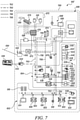
- FIG. 7 illustrates an exemplary control system 700 for a machine 100' contemplating an exemplary implementation of the retrofit remote control system of the present disclosure.
- the control system 700 includes a number of base machine components 602, retrofit remote control system components 604 and retrofit MAS components 606 implemented to facilitate operating the machine 100' in tele remote operation mode, semi-autonomous or fully autonomous mode from an off-board remote control 630 or a remote operator station (not shown).
- the control system 700 includes a plurality of communication links disposed on the machine 100' through which the components of the control system 700 communicate with one another.
- control system 700 includes a first Controller Area Network (CAN) 702, a second CAN 703, a datalink (DL) 704, an Ethernet Local Area network (LAN) 708, and a plurality of direct I/O control links 706 for implementing the communication links within the control system 700.
- CAN Controller Area Network
- DL datalink
- LAN Ethernet Local Area network
- the control system 700 includes a first interface control module 626 and a second interface control module 628 retrofitted on to the machine 100' to enable remote controlling of the machine 100' and its components remotely from the off-board remote control 630.
- the off-board remote control 630 is a Line of Sight (LOS) operator console (hereinafter interchangeably referred to as the LOS operator console 630).
- the first interface control module 626 and the second interface control module 628 communicate with the off-board remote control 630 over a wireless communication channel 632 via a LOS transceiver 634.
- the wireless communication channel 632 may include, but not limited to a Frequency Hopping Spread Spectrum (FHSS) communication channel, radio broadcasting system, Wi-fi communication channel, and so on.
- FHSS Frequency Hopping Spread Spectrum
- the on-board control modules 603 include a transmission ECM 608, a machine ECM 610, and an engine ECM 612.
- the interface control modules 626, 628 are configured to send control signals to the on-board control modules 603 (i.e., the transmission ECM 608, the machine ECM 610 and the engine ECM 612) via the first CAN 702 and the datalink 704 control, as will be explained in further detail in the following description.
- the transmission ECM 608 is configured to generate (output) control signals, based on received (input) control signals, to control operation of a transmission controls of the machine 100' (such as transmission controls 134 of the transmission 112 as shown in FIGS. 1 and 2 ).
- the transmission ECM 608 may control transmission speed, transmission mode (drive, reverse, parking brake, neutral), and related operations of the transmission of the machine 100'.
- the transmission input control signals are received by the interface control modules 626, 628 from the off-board remote control 630 via the (on-board) LOS transceiver 634, the second CAN 703, and are subsequently communicated to the transmission ECM 608 over the first CAN 702 and the datalink 704.
- the transmission ECM 608 is also configured to transmit data, including control feedback, to the interface control modules 626, 628 and subsequently to the off-board remote control 630 over the same communication channels as the input control signals.
- the transmission input control signals may also be received from the machine ECM 610.
- the control signals received from the machine ECM 610 are based on control signals received from an ECM of the remote operator station (not shown), transmitted from an off-board-transceiver to the local transceiver 682 (such as over a separate wireless communication channel 684), subsequently communicated to the AECM 674 via a local router 672, a first switch 676 and Ethernet LAN 708, further to the interface control modules 626, 628 and finally to the machine ECM 610 over the first CAN 702 and the DL 704.
- output control signals generated by the off-board remote control 630 may be communicated to the interface control modules 626, 628 via the (on-board) LOS transceiver 634, and subsequently to the machine ECM 610 and finally to the transmission ECM 608 over the first CAN 702 and the DL 704.
- the machine ECM 610 is configured to generate output control signals, based on received input control signals, to control movement of the machine 100' and/or operation of the transmission ECM 608 (e.g., traction control, ride control, power management, braking, throttling), to control operation of an implement of the machine 100', to actuate one or more horns, indicators (e.g., parking brake indicator) or the like disposed on the machine 100'.
- the transmission ECM 608 e.g., traction control, ride control, power management, braking, throttling
- the input control signals for the machine ECM 610 may be received by the interface control modules 626, 628 from the off-board remote control 630 (via the (on-board) LOS transceiver 634 and the second CAN 703), and are subsequently sent to the machine ECM 610 over the first CAN 702 and the DL 704. In some implementations, the input control signals may also be received from the AECM 674.
- the control signals received from the AECM 674 are based on control signals received from the ECM of the remote operator station, that are transmitted from an off-board-transceiver to the local transceiver 682, to the AECM 674 via the local router 672, the first switch 676 and the Ethernet LAN 708, and subsequently to the interface control modules 626, 628 and finally to the machine ECM 610 over the first CAN 702 and the DL 704.
- the machine ECM 610 is also configured to transmit data, including control feedback, to the interface control modules 626, 628 and subsequently to the off-board remote control 630 over the same communication channels as the input control signals.
- the engine ECM 612 is configured to generate output control signals, based on received input control signals, to control operation of the engine of the machine 100' (such as the engine controls 130 associated with the engine 110 shown in FIGS. 1 and 2 ).
- the engine ECM 612 may be configured to control engine speed, acceleration, and so on.
- the engine ECM 612 may also be configured to control the components and operation of an engine cooling system of the machine 100' (such as controlling the engine cooling system controls 140 shown in FIG. 2 ).
- the engine input control signals may be received by the interface control modules 626, 628 from the off-board remote control 630 via the (on-board) LOS transceiver 634 and the second CAN 703, and are subsequently sent to the engine ECM 612 over the first CAN 702 and the DL 704.
- the engine input control signals may also be received from the machine ECM 610.
- the control signals received from the machine ECM 610 are based on control signals received from an ECM of the remote operator station (not shown), transmitted from an off-board-transceiver to the local transceiver 682, that are subsequently communicated to the AECM 674 via the local router 672, a first switch 676 and Ethernet LAN 708, and further to the interface control modules 626, 628 and finally to the machine ECM 610 over the first CAN 702 and the DL 704.
- output control signals generated by the off-board remote control 630 may be communicated to the transmission ECM 608 via the (on-board) LOS transceiver 634, the interface control modules 626, 628 and the machine ECM 610 over the first CAN 702 and the DL 704.
- the engine ECM 612 is also configured to transmit data, including control feedback, to the interface control modules 626, 628 and subsequently to the off-board remote control 630 over the same communication channels as the input control signals.
- the control system 700 further includes one or more I/O control components 639 disposed on the machine 100' and operatively connected to the interface control modules 626, 628 via direct I/O link 706.
- the I/O control components 639 may include, but not limited to, an enclosure cooling fan 640, enclosure temperature sensor 642, ACE switch 644, strobe lights (including red 646, amber 648 and green 650), expander relays 652, engine start-stop controls 654, power relays 656, work light assembly 658, fire suppression system 660, horn assembly controls 662, attachment relays 664, and implement and steer controls 666 and 668, respectively.
- the engine start-stop controls 654 may be configured to receive control signals from the interface control modules 626, 628 and send I/O based control signals to the engine ECM 612 via the I/O link 706.
- the relays 652, 656, 664 may be configured to convert low current signals received from the interface control modules 626, 628 into high current I/O based control signals to the ad-hoc components, such as the horn assembly controls 662, the strobe lights 646, 648, 650, and so on via the direct I/O link 706.
- the input commands from the off-board remote control 630 are first received by the interface control modules 626, 628 via the LOS transceiver 634, and the second CAN 703, and then subsequently sent to the individual I/O control components 639 via their respective direct I/O control links 706.
- the first CAN 702 is disposed on the machine 100' and is configured to operatively connect the interface control modules 626, 628, the AECM 674, a positioning system 688, the transmission ECM 608, the machine ECM 610, the engine ECM 612, the cab service port 618, the display 614, the keyboards 616, a tire monitoring system (TMS) transceiver (TMS) 620, and a rear view camera system (including rear view camera 622 and a rear view display 624).
- TMS tire monitoring system
- TMS rear view camera system
- the datalink (DL) 704 is also disposed on the machine 100' and is configured to operatively connect the interface control modules 626, 628, the positioning system 688, the transmission ECM 608, the machine ECM 610, the engine ECM 612, the display 614, the cab service port 618 and a service port 670.
- the service ports 618, 670 may be connection ports to connect add-on devices to the machine 100 and the interface control modules 626, 628 (such as, for servicing, configuration, updates to the interface control modules 626, 628, etc.).
- the cab service port 618 may be an on-board component of the machine 100' whereas the service port 670 may be a part of the retrofit remote control system components 604.
- the local transceiver 682 may be disposed on the remotely operated machine 100'.
- the local transceiver 682 may be an Ethernet-compatible, wireless radio compatible transceiver.
- the local transceiver 682 may include one or more antennas 683.
- the local transceiver 682 is in operable communication with the off-board transceiver, the local router 672 (discussed herein below) and a remote shutdown module (RSM) 686.
- RSM remote shutdown module
- the local transceiver 682 is in communication with the local router 672 and the RSM 686 via the Ethernet LAN 708.
- the local transceiver 682 is configured to receive (wirelessly) control signals, safety signals and data from the off-board transceiver and is configured to transmit data from the MAS 606 to the off-board transceiver at the remote operator station.
- the received control signals may be generated by the ECM at the remote operator station (based on an operator input received from one or more I/O devices positioned at the remote operator station) and may control the operation of the machine 100' and its systems via the AECM 674 and the retrofit interface control modules 626, 628.
- the data transmitted by the local transceiver 682 to the off-board transceiver may include video data (captured by one or more IP cameras 678), audio data (captured by a microphone 680) related to the operation of the machine 100' and the work area adjacent to the machine 100', positional and distance measurement information from one or more LADARs 681, machine 100' operational or health related data, and other information collected and transmitted to the off-board remote control 630.
- the off-board remote control 630 can additionally transmit the information to the remote operator station for monitoring/logging or display/replaying (e.g., video data and audio data).
- the local transceiver 682 is configured to support multiple Service Set Identifiers (SSID), thus allowing the local transceiver 682 to function on multiple subnetworks within the control system 700.
- the local transceiver 682 may be configured to utilize Multi-in Multi-out (MIMO) 802.1 IN technology, which provides improved bandwidth and signal integrity when compared to a Single-In Single-Out 802.11G radio operating in diversity mode.
- the antennas 683 may be, for example, dual band MIMO (2.4/5 GHZ) antennas.
- the local transceiver 682 is also configured to support Profinet.
- Profinet defines the communication with field connected peripheral devices. Its basis is a cascading real-time concept. Profinet may be used to define the data exchange between controllers and devices, as well as parameter setting and diagnosis.
- the local router 672 is retrofitted on the machine 100' and includes a local router processor.
- the local router 672 is in operable communication via the Ethernet LAN 708 with the local transceiver 682, the first switch 676, the RSM 686 and the service port 670.
- the local router 672 is also in operable communication with the AECM 674 and the environment monitoring system 675 via the first switch 676 and Ethernet LAN 708.
- the local router 672 is also in operable communication with the machine ECM 610, the cab service port 618, the transmission ECM 608, the engine ECM 612, the display 614, the keyboards 616 and the positioning system 688 via the interface control modules 626, 628, the service port 670, the first CAN 702, the datalink 704 and the Ethernet LAN 708.
- the first switch 676 is disposed on the machine 100' and is in operable communication with at least the local router 672, the environment monitoring system 675 (i.e., the IP cameras 678, microphone 680 and LADARs 681), the AECM 674 and the interface control modules 626, 628 via the Ethernet LAN 708.
- the first switch 676 is configured to transmit and receive control signals/safety signals from the local router 672, and data from, at least, the environment monitoring system 675, the AECM 674 and the interface control modules 626, 628.
- the first switch 676 is configured to transmit data only to the one or more devices for which the message was intended.
- the first switch 676 has a Dynamic Host Configuration Protocol (DHCP) address assignment which allows devices, for example the IP cameras 678, the LADARs 681 and the microphone 680, to be fitted or replaced without manually configuring static IP addresses.
- DHCP is a standardized network protocol used for dynamically distributing network configuration parameters, such as IP addresses, reducing the need for a user to configure such parameters manually.
- the service port 670 is retrofitted on the machine 100' and is in operable communication with the transmission ECM 608, the machine ECM 610, and the engine ECM 612 and the positioning system 688 via the interface control modules 626, 628, the first CAN 702 and the datalink 704.
- the AECM 674 is configured to receive the control signals and data via the local router 672 and/or the first switch 676.
- the AECM 674 may also receive control signals from the cab service port 618.
- the control signals may be generated by the off-board remote control 630, and/or the remote operator station.
- the AECM 674 is further configured to process the control signals and data, generate (output) control signals based on the processed control signals and data, and transmit such control signals to the environment monitoring system 675, the display 614 or one or more of the transmission ECM 608, the machine ECM 610, the engine ECM 612 via the interface control modules 626, 628, wherein the control signals control an operation of the machine 100' and its components.
- control signals are received by the on-board control modules 603, they implement the instructions/commands of the control signal by sending control commands to their respective machine components via the first CAN 702 and/or the datalink 704.
- the on-board control modules 603 implement control signals from the AECM 674 and/or the interface control modules 626, 628 that are based operator input to the off-board remote control 630 or the remote operator station, they also monitor and regulate certain functions of the machine 100'.
- advanced machine control features such as traction control, ride control, power control and the like, will still operate as normal while the machine 100' is under tele remote, semi-autonomous or autonomous mode of operation.
- the AECM 674 may transmit a control signal that instructs the machine ECM 610 to apply braking via the interface control modules 626, 628. While the machine ECM 610, in response to the control signal, may actuate the brakes, the machine ECM 610 may still continue to implement power management (an advanced machine control feature).
- the AECM 674 may receive data from one or more on-board control modules 603, the interface control modules 626, 628, the positioning system 688, the local router 672 and the first switch 676 of the Ethernet LAN 708.
- the AECM 674 is also configured to receive data captured by various sensors disposed on the machine 100' (e.g., the articulation sensor 638, the inertial measurement unit (IMU) sensor 636, and the like).
- the AECM 674 receives data from the IMU 636 (in one embodiment, via the second CAN 703) and uses such data to determine acceleration and machine inclination angle.
- the IMU sensor 636 may be disposed on the rear end of the machine 100' (such as the rear end 108 shown in FIG.1 ).
- the AECM 674 receives data from the engine and transmission speed sensors to determine engine revolutions per minute (RPM) and machine ground speed.
- the AECM 674 is configured to determine machine direction, implement position and machine mode. In tele remote, semi-autonomous or autonomous modes, when the remote operator is controlling the machine, the maximum available gear may be restricted. For example, the machine 100' may be limited to operation in first gear.
- the AECM 674 is also configured to control certain (machine 100') functions, such as ground condition monitoring, automatic steering/turning (when activated by the operator) etc.
- the AECM 674 is also configured to forward certain operator requests for advanced control features from the off-board remote control 630 or the remote operator station to the appropriate the on-board control modules 603, such as performing automatic dig position).
- automatic dig position is requested/enabled, the depth and loading of the implement, such as the bucket 116 in a material is automatically controlled by the machine 100' in response to a productivity value.
- the AECM 674 may also be configured to provide data to payload type systems that analyze load times, number of passes and payload data to determine efficiency optimization. Similarly, the AECM 674 may be configured to support tire monitoring, as well.
- the AECM 674 is also configured to transmit data via the local transceiver 682, including feedback information, to the remote operator station.
- the AECM 674 is configured to transfer control of the machine 100' to the off-board remote control 630 (i.e., the LOS operator console 630) for machine recovery purposes, when the machine ECM 610 detects that signals are being received from both the AECM 674 and the LOS operator console 630, as discussed later herein.
- control system 700 includes a number of exemplary components of the control system 700, it will be contemplated by a person skilled in the art that the machine 100' and the control system 700 may include additional components that are omitted from the description for the sake of brevity of the present disclosure.
- the retrofit remote control system 200 facilitates enabling remote control functionalities in a machine which is inherently incapable of being remote controlled. For example, any type of machine can be converted to a remote controlled machine and even extended to a fully autonomous machine by simply retrofitting the retrofit remote control system 200 and the MAS 400 on to the machine. Accordingly, a user can convert any of their old models of machines to being remote controlled, instead of buying a new machine.
- the interface control module 202 is capable of adapting to any configuration of the machine 100 irrespective of whether the machine 100 includes electrohydraulic controls or not. Therefore, if a machine 100 includes any on-board control modules, then the interface control module 202 can simply connect with those on-board control modules and control the machine components via the on-board control modules. Whereas, in case the machine does not include any on-board control module, then the interface control module 202 will control the machine components via direct I/O control links. Similarly, in case of a combination of different types of components, the interface control module 202 will use a combination of both the datalink controls as well as direct I/O based controls, as explained in the embodiments above.
- the interface control module 202 detects presence of an transmission ECM, then the transmission control signals are send to the transmission gear solenoids via the transmission ECM whereas if there is no transmission ECM detected, then the interface control module 202 will send control signals over the direct I/O control link to the transmission gear solenoids.
- the interface control module 202 can adapt to any type of machine configuration and control all types of machine components, thereby making the retrofit remote control system 200 generic and suitable for all types of machines. For example, in case of a wheel loader, the interface control module 202 will be able to control the bucket implement controls, while in case of a truck, the interface control module 202 will be able to control the hoist controls.
- FIG. 8 illustrates an exemplary interface control module 802 retrofitted onto another type of machine, such as an underground articulated truck (UAT) 800.
- the interface control module 802 may be housed within a housing 804.
- the housing 804 may be positioned within an operator cabin 806 of the UAT 800, behind an operator seat.
- the interface control module 802 may connect to one or more on-board control modules, such as machine ECM, transmission ECM, implement ECM, etc., (not shown) via on-board CAN and datalink of the UAT 800.
- the interface control module 802 may also be connected to the in-cab machine controls, such as brakes, accelerator, etc., and implement controls via direct I/O controls or on-board CAN or datalink connections (not shown).
- ad-hoc components may be retrofitted onto the UAT 800 by connecting them to the interface control module 802 via direct I/O controls, such as harness 816.
- LADARs 808, 810 may be retrofitted onto a front end 812 and a rear end 814, respectively, of the UAT 800 and connected to the interface control module 802 via the harness 816.
- One or more cameras 818, 820 may also be retrofitted onto the UAT 800 and connected to the interface control module 802 via the harness 816.
- the LADARs 808, 810 along with the cameras 818, 820 may be retrofitted to facilitate environment monitoring while operating the UAT 800 remotely.
- other ad-hoc components such as strobe light assembly, fire suppression system, positioning system, may also be retrofitted onto the UAT 800 and connected to the interface control module 802 via the harness 816, in a similar manner.
- the interface control module 202 further acts as an interface between the base machine components and MAS 400.
- the MAS 400 can also be retrofitted on to the machine 100 and MAS 400 will control the machine components by sending control signals to the machine components via the interface control module 202, which in turn sends the control signal to the respective machine component over either the datalink connection or the I/O control link, as applicable.
- the interface control module 202 facilitates addition of many ad-hoc components that too can be retrofitted on the machine 100 to provide enhanced functionalities that were originally not there on the machine 100.
- FIG. 9 illustrates an exemplary method 900 for enabling remote controlling of one or more on-board components 126 of the machine 100 that are inherently incapable of being remote controlled.
- the interface control module 202 is retrofitted on to the machine 100.
- the interface control module 202 is capable of wireless communication with the off-board remote control 204 over a wireless communication channel 206.
- a machine type and machine configuration, to which the retrofit remote control system 200 is connected is detected, such as by the machine detection module 216.
- the machine detection module 216 may receive an input from the off-board remote control 204 indicating a predefined machine type to which the retrofit remote control system 200 is connected.
- the machine detection module 216 may provide a list of machine types to the I/O unit 304 of the off-board remote control 204 and receive a user selection of the machine type from the off-board remote control 204.
- the machine detection module 216 may also receive a machine identification and/or any other information related to the machine type and machine configuration from the off-board remote control 204.
- the configuration of the machine 100 and its on-board components 126 is detected, such as by the processing module 218.
- the processing module 218 may be configured to communicate with a machine database 230 that includes the various configuration details of all the machine types.
- the machine configuration details may be received along with the machine identification from the operator via the off-board remote control 204.
- the machine database 230 may store the details about every machine, including the machine type, machine model number, machine make year, machine manufacturer, machine configuration details and so on.
- the machine configuration details may include the details about the various on-board components of every type of machine, their respective control links, the one or more on-board control modules associated with each type of machine, and so on.
- step 906 presence of any on-board control modules on the machine 100 is detected, such as by the processing module 218.
- the processing module 218 may be configured to extract the details of the on-board control modules 152 from the machine configuration received from the machine database 230.
- the operator of the machine 100 may manually feed the details of the on-board control modules 152 present on the machine 100.
- the control capabilities of each of the on-board components 126 of the machine 100 is detected, such as by the processing module 218.
- the processing module 218 is configured to identify that the on-board components (such as components 145) that are controlled by the on-board control modules (such as by on-board control modules 152) are capable of datalink control, whereas all the other on-board components (such as components 147) that are not controlled by any on-board control modules are capable of only direct I/O controls.
- a digital communication link is established with the on-board control modules 152 for controlling the datalink control components 145 of the machine 100.
- the interface control module 202 is configured to establish a communication link with the on-board control modules 152 over the digital communication channel 144 disposed on the machine 100.
- a direct I/O control link 146 is established with each of the on-board components 126 that are capable of being controlled solely by direct I/O controls (such as the components 147).
- the direct I/O control link 146 between the interface control module 202 and each of the individual components on the machine 100 may be supplemented with appropriate wiring and harnessing disposed on the machine 100 to connect the individual component with the interface control module 202.
- a remote operation command is wirelessly received from the off-board remote control 204 over the wireless communication channel 206.
- control signal is sent over either the digital communication channel 144 or the direct I/O control link 146, 236.
- the processing module 218 may identify the relevant component of the machine 100 to which the input operation command is associated with and accordingly sends the control signal over either the digital communication channel 144 or the direct I/O control link 146 or 236.
- the method 900 may further include retrofitting the machine automation system MAS (400) to the machine 100, such that the MAS 400 communicates and controls the machine components via the interface control module 202, in the manner described above in reference to FIGS. 5 and 7 .
Abstract
Description
- The present disclosure generally relates to systems and methods for remote controlling of a machine. More particularly, the present disclosure relates to a retrofittable remote control system for a machine that is inherently incapable of being remotely controlled.
- Many machines used in construction, earth-moving, mining and agriculture industries operate in challenging environments. For example, mining trucks operate in underground mines, where the operating conditions may be difficult and many a times, not suitable for manual operations. In recent efforts to improve safety, many companies are developing machines with remote operation capabilities so that an operator can operate the machine from a remote and safe location.
- Additionally, there are numerous remote control kits available in the market, that can be retrofitted onto a machine to facilitate remote operations of that particular machine. Nevertheless, due to different electrical, electronic, and other control systems used in different types of machines, these remote control kits are typically specific to each of these different types of machines. Moreover, these remote control kits require a certain level of basic communication capabilities within the machine, for facilitating remote controlling of the machine and its components. However, all such conventional remote control kits are very complex and expensive, and hence not very desirable.
-
US Patent No. 9,418,542 - In an aspect of the present disclosure, a retrofittable remote control system is provided for enabling remote controlling of an on-board component of a machine that is inherently incapable of being remote controlled. The retrofittable remote control system includes an interface control module and an off-board remote control configured to communicate with the interface control module over a wireless communication channel. The interface control module is configured to be retrofitted on the machine and is configured to detect presence of an on-board control module associated with the on-board component of the machine. The on-board control module is configured to communicate with the on-board component over a digital communication channel disposed on the machine. The interface control module is configured to establish a digital communication link with the on-board control module over the digital communication channel when the on-board control module is detected to be present on the machine and establish a direct Input / Output (I/O) communication link with the on-board component of the machine when the on-board control module is detected to be absent from the machine. The interface control module is configured to receive a remote operation command from the off-board remote control to control the on-board component of the machine. Further, the interface control module is configured to send, based on the detection, a control signal over one of the direct I/O communication link or the digital communication channel via the detected on-board control module, for controlling the on-board component of the machine, the control signal being corresponding to the wirelessly received remote operation command.
- In another aspect of the present disclosure, a method for enabling remote controlling of an on-board component of a machine that is inherently incapable of being remote controlled. The method includes retrofitting an interface control module on to the machine, the interface control module being configured to communicate with an off-board remote control over a wireless communication channel. Further, the method includes detecting, by the retrofitted interface control module, presence of an on-board control module associated with the on-board component of the machine, the on-board control module being configured to communicate with the on-board component over a digital communication channel. The method includes establishing, by the interface control module, a digital communication link with the on-board control module over the digital communication channel when the on-board control module is detected to be present on the machine and establishing, by the interface control module, a direct Input / Output (I/O) communication link with the on-board component when the on-board control module is detected to be absent from the machine. Furthermore, the method includes wirelessly receiving, by the interface control module, a remote operation command from the off-board remote control over the wireless communication channel to control the on-board component of the machine. The method includes sending, by the interface control module, based on the detection, a control signal over one of the direct I/O communication link or the digital communication link via the detected on-board control module, for controlling the on-board component, the control signal being corresponding to the wirelessly received remote operation command.
- In a yet another embodiment, a machine is provided. The machine includes an on-board component inherently incapable of being remotely controlled. The machine further includes a retrofit remote control system operatively connected to the on-board component and configured to enable remote controlling of the on-board component. The retrofit remote control system includes an interface control module and an off-board remote control configured to communicate with the interface control module over a wireless communication channel. The interface control module is configured to be retrofitted on the machine and is configured to detect presence of an on-board control module associated with the on-board component of the machine. The on-board control module is configured to communicate with the on-board component over a digital communication channel disposed on the machine. The interface control module is configured to establish a digital communication link with the on-board control module over the digital communication channel when the on-board control module is detected to be present on the machine and establish a direct Input / Output (I/O) communication link with the on-board component of the machine when the on-board control module is detected to be absent from the machine. The interface control module is configured to receive a remote operation command from the off-board remote control to control the on-board component of the machine. Further, the interface control module is configured to send, based on the detection, a control signal over one of the direct I/O communication link or the digital communication channel via the detected on-board control module, for controlling the on-board component of the machine, the control signal being corresponding to the wirelessly received remote operation command.
-
-
FIG. 1 illustrates an exemplary machine operating on a worksite, in accordance with the embodiments of the present disclosure; -
FIG. 2 illustrates an exemplary control system of the machine having a retrofit remote control system, in accordance with the embodiments of the present disclosure; -
FIG. 3 illustrates an exemplary retrofit remote control system having an interface control module retrofitted to the machine, in accordance with the embodiments of the present disclosure; -
FIG. 4 illustrates an exemplary off-board remote control of the retrofit remote control system, in accordance with the embodiments of the present disclosure; -
FIG. 5 illustrates an exemplary machine automation system (MAS) having an autonomy electronic control module (AECM) retrofitted to the machine, in accordance with the embodiments of the present disclosure; -
FIG. 6 illustrates an exemplary block diagram of an on-board control module of the machine, in accordance with the embodiments of the present disclosure; -
FIG. 7 illustrates a schematic of an exemplary control system of the machine having the retrofit remote control system and MAS, in accordance with the embodiments of the present disclosure; -
FIG. 8 illustrates an exemplary interface control module retrofitted onto an underground articulated truck, in accordance with an embodiment of the present disclosure; and -
FIG. 9 illustrates an exemplary flowchart for a method of enabling remote controlling of a machine that is inherently incapable of being remote controlled, in accordance with the embodiments of the present disclosure. - Reference will now be made in detail to specific embodiments or features, examples of which are illustrated in the accompanying drawings. Generally, corresponding reference numbers will be used throughout the drawings to refer to the same or corresponding parts.
- The present disclosure relates to a retrofittable remote control system for enabling remote control of a machine that is inherently incapable of being remote controlled. To this end,
FIG. 1 illustrates anexemplary machine 100 configured to operate at aworksite 101. Theworksite 101 may include a mine site, a land fill, a quarry, a construction site, or any other type of worksite. As shown inFIG. 1 , themachine 100 is embodied as an underground mining machine, such as an underground a load haul dump (LHD) machine. However, it may be contemplated thatmachine 100 may be any type of machine configured to perform some type of operation associated with an industry such as mining, construction, farming, transportation, or any other industry. Other examples ofmachine 100 may include, but are not limited to, an off-highway truck, an articulated truck, a paver screed, an excavator, a backhoe loader, a skid steer loader, a wheel loader, a compactor, or the like. In an embodiment of the present disclosure, themachine 100 is a manned machine which is incapable of being remote controlled by itself. - As shown in
FIG. 1 , themachine 100 includes amachine frame 102 with a set ofground engaging members 104, such as wheels or tracks, coupled with theframe 102. Theframe 102 defines afront end 106 and arear end 108. The terms 'front' and 'rear', as used herein, are in relation to a direction of travel of themachine 100, as represented by arrow, T, inFIG. 1 , with said direction of travel being exemplarily defined from therear end 108 towards thefront end 106. The movement of theground engaging members 104 may be powered by a power source, such as anengine 110 via atransmission 112 and/or mechanical and electrical drive train (not shown). In the illustrated example, theengine 110 may be housed within an engine compartment (not shown) positioned towards therear end 108 of themachine 100. Further, theengine 110 may be based on one of the commonly applied power generation units, such as an internal combustion engine (ICE) having a V-type configuration, inline configuration, or an engine with different configurations, as are conventionally known. However, aspects of the present disclosure need not be limited to a particular type of power source. Although the power source is shown and described to be an engine, it may be contemplated that power source may also be embodied as a battery, a fuel cell, electric generator, a turbine or any other suitable device configured to power themachine 100. Additionally, in some alternative implementations, themachine 100 may include multiple power sources positioned at thefront end 106 and at therear end 108 of themachine 100. - The
machine 100 further includes an implement 114, such as abucket 116. Themachine 100 may also include a pair oflift arms 118 that are movably coupled to theframe 102 at thefront end 106. The implement 114 is pivotally connected to one end of thelift arms 118 by any suitable coupling mechanism, such as coupler, pin, latches, or any other mechanism generally known in the art. Themachine 100 further includes one ormore lift cylinders 120 that couple thelift arms 118 to theframe 102. Thelift cylinders 120 are extended or retracted to raise or lower thelift arms 118. Although the implement 114 is shown and described to be abucket 116, it may be contemplated that in other embodiments of the present disclosure, other types of implements, such as, but not limited to, dump body, ejector body, blades, scrapers, grapples, or the like may also be employed by themachine 100. Additionally, the position of the implement 114 being at thefront end 106 of themachine 100 is exemplary and other positions of the implement may also be contemplated without limiting the scope of the claimed subject matter. - The
machine 100 further includes anoperator cab 122 that may be supported on theframe 102. Theoperator cab 122 includes an operator seat (not shown) and anoperator console 124, that may include various input output controls for operating themachine 100. For example, theoperator console 124 may include, but not limited to, one or more of steering wheel, touch screens, joysticks, switches etc., to facilitate an operator in operating themachine 100 and one or more components of themachine 100. - In an embodiment of the present disclosure, as shown in
FIGS. 1 &2 , themachine 100 includes a plurality of on-board components 126 and acontrol system 128 for controlling the on-board components 126 and operating themachine 100. Examples of the on-board components 126 may include, but not limited to, engine controls 130, machine controls 132, transmission controls 134, implementcontrols 136, work light controls 138, engine cooling system controls 140, tire monitoring system controls 142, horn assembly controls 148, cab door actuation mechanism controls 150, indicator system controls 151, and so on. - The engine controls 130 may include one or
more engine 110 related controls and actuators, such as engine throttle, starter solenoid, intake and exhaust valves, fuel injector /spark plug timers, engine crankshaft, piston, timing belt, and so on, that facilitate operations of theengine 110 of themachine 100. In an alternative embodiment, in case of a battery operated machine, themachine 100 may include battery controls (not shown) that facilitate operations of the battery system (not shown) of themachine 100. Machine controls 132 may include one or more machine related controls, such as traction controls, brakes controls, in-cab controls (including steering controls, joystick controls, etc.) and input/output devices (such as those in operator console 124), and so on that facilitate in operations of themachine 100. Further, the transmission controls 134 may include all the components and actuators in thetransmission 112 of themachine 100. Example of transmission controls 134 may include, but not limited to, transmission solenoids, torque converter clutch solenoid, pressure control solenoids, and so on. The implementcontrols 136 may include controls and actuators for controlling the implement 114. Examples of the implementcontrol 136 may include, but not limited to, thelift cylinders 120, the implement solenoids, hoist controls, and so on. It may be contemplated that the implementcontrols 136 of themachine 100 will vary according to the machine type. The work light controls 138 includes the controls and switches for operating the work lights, such as the head light, fog-lights, break lights, and so on. - Furthermore, the engine cooling system controls 140 includes controls and actuators for operating the various components of an engine cooling system of the
machine 100. For example, the engine cooling system controls 140 may include, but not limited to, controls for radiator, cooling fan, thermostat, radiator cap, and so on. The tire monitoring system controls 142 may include components and actuators for monitoring air pressure inside theground engaging members 104 of themachine 100 and provide the monitored information to an operator of themachine 100 via input/output devices included in theoperator console 124 of themachine 100. Similarly, the horn assembly controls 148 may include the actuators and switches for activating horn during operation of themachine 100. The cab door actuation mechanism controls 150 may include actuators and switches for operating a cab door of theoperator cab 122 of themachine 100. Furthermore, the indicator system controls 151 may include actuators and switches for activating turning indicators (including left and right turn indicators disposed on the front and rear of the machine 100) and/or parking brake indicators, etc., as the machine operates at theworksite 101. - It may be contemplated by a person skilled in the art, that the above mentioned list of on-
board components 126 are merely exemplary and does not represent a comprehensive list of all the on-board components and themachine 100 may include additional components as well. The list of on-board components 126 is merely for explanation purposes and is in no way intended to be limiting the scope of the claimed subject matter. Further, details and operations of these on-board components 126 are known in the art and hence not included herein for the sake of brevity of the present disclosure. - The
control system 128 of themachine 100 includes one or moredigital communication channel 144 for facilitating communication of information related to operating themachine 100. Examples of thedigital communication channel 144 may include, but not limited to, one or more of Control Area Network (CAN) bus, datalink communication channel, Ethernet cables, and any other known wired digital communication channel. It may be contemplated that thedigital communication channel 144 may include one or more of coaxial cables, copper wires, fiber optics, and so on. - In an embodiment of the present disclosure, some of the on-
board components 126 may include electrohydraulic controls and are capable of digitally communicating and being controlled, while the other on-board components may only be capable of being controlled via direct Input / Output (I/O) control links 146. For the purposes of explanation of this disclosure, the on-board components 126 are divided into two sub-sets, i)datalink control components 145; and ii) I/O control components 147. Thedatalink control components 145 are the components that are connected to thedigital communication channel 144 for receiving control commands while the I/O control components 147 are the ones that are not connected to thedigital communication channel 144 and instead receive control commands via their respective I/O control links 146. - In the illustrated exemplary embodiment, the engine controls 130, the transmission controls 134, the machine controls 132, the engine cooling system controls 140 and the tire monitoring system controls 142 are shown to be
datalink control components 145 that are connected to thedigital communication channel 144 for receiving control commands. On the other hand, the implementcontrols 136, the work light controls 138, and other accessories, such as horn assembly controls 148, cab-door actuation mechanism controls 150, indicator system controls 151 may be I/O control components 147 that receive control commands via their direct I/O control links 146 disposed on themachine 100. It may be understood by a person skilled in the art that the direct I/O control links 146 may be implemented as direct one-on-one mechanical and/or hydraulic connections implemented via wires, relays and switches to connect each of the on-board I/O control components 147 with their respective actuators or switches that may be, in turn, operated by an operator of themachine 100. - Further, the
control system 128 of themachine 100 may include one or more on-board control modules 152 disposed on themachine 100 and configured to communicate with and control each of thedatalink control components 145 of themachine 100 via thedigital communication channel 144. In an exemplary embodiment of the present disclosure, the on-board control modules 152 may include, but not limited to, a machine Electronic Control Module (ECM) 154, atransmission ECM 156, and anengine ECM 158. - The
machine ECM 154 may be configured to, based on input commands and signals, operatively communicate with and control the on-board machine controls 132 via thedigital communication channel 144. For example, themachine ECM 154 is configured to send output control signals over thedigital communication channel 144, in response to one or more input signals, to control the traction controls, brakes, in-cab controls (including steering controls, joystick controls, etc.), input/output devices (such as those in operator console 124), and so on, that facilitate in operations of themachine 100. Further, themachine ECM 154 is also configured to communicate with and control the tire monitoring system controls 142 for monitoring the air pressure within theground engaging members 104 of themachine 100. Additionally, in some embodiments, themachine ECM 154 may also be configured to communicate with thetransmission ECM 156 and theengine ECM 158 for controlling the transmission controls 134, the engine controls 130, as well as the engine cooling system controls 140. - The
control system 128 may include one ormore machine sensors 159 disposed on themachine 100 and configured to monitor one or more machine parameters associated with the machine controls 132. The one ormore machine sensors 159 are also communicatively coupled to thedigital communication channel 144 and may be configured to provide input signal including the respective monitored machine parameter to themachine ECM 154 for controlling the one or more of the machine controls 132 and/or the tire monitoring system controls 142. Examples of themachine sensors 159 may include, but not limited to,temperature sensor 160,fuel sensor 162,accelerometer 164,tire pressure sensors 166, and so on. Thesemachine sensors 159 are all known in the art and hence not described in greater detail for the sake of brevity of the present disclosure. - The
transmission ECM 156 may be configured to, based on input commands and signals, operatively communicate with and control the on-board transmission controls 134 via thedigital communication channel 144. For example, thetransmission ECM 156 may be configured to send control commands over thedigital communication channel 144, based on one or more inputs, to control the transmission controls 134. Examples of the transmission controls 134 include, but not limited to, transmission solenoids, torque converter clutch solenoid, pressure control solenoids, and so on, disposed on themachine 100. - The
control system 128 further includes one ormore transmission sensors 167 disposed on themachine 100 and configured to monitor one or more transmission related parameters associated with the transmission controls 134. The one ormore transmission sensors 167 are also communicatively coupled to thedigital communication channel 144 and may be configured to provide input signal including the respective monitored transmission related parameter to thetransmission ECM 156 for controllingtransmission 112 of themachine 100. Examples of thetransmission sensors 167 may include, but not limited to, athrottle position sensor 168,vehicle speed sensor 170, transmissionfluid temperature sensor 172, and so on. Thesetransmission sensors 167 are also known in the art and hence not described in greater detail for the sake of brevity of the present disclosure. - Furthermore, the
engine ECM 158 may be configured to, based on input commands and signals, operatively communicate with and control the on-board engine controls 130 via thedigital communication channel 144. Additionally, theengine ECM 158 may also be configured to communicate with and control the engine cooling system controls 140 via thedigital communication channel 144. For example, theengine ECM 158 may be configured to send control commands over thedigital communication channel 144, based on one or more inputs, to the engine throttle, starter solenoid, intake and exhaust valves, fuel injector /spark plug timers, engine crankshaft, piston, timing belt, and so on, that facilitate operations of theengine 110. Similarly, theengine ECM 158 may be configured to send control commands over thedigital communication channel 144, based on one or more inputs, to the radiator, cooling fan, thermostat, radiator cap, etc., that facilitate in operating the engine cooling system controls 140 of themachine 100. It may be contemplated that in case of a battery operated machine, a battery control module (not shown) may also be implemented to control the battery controls via thedigital communication channel 144. - The
control system 128 further includes one ormore engine sensors 173 disposed on themachine 100 and configured to monitor one or more engine related parameters associated with theengine 110, the engine controls 130, and the engine cooling system controls 140. The one ormore engine sensors 173 are also communicatively coupled to thedigital communication channel 144 and may be configured to provide input signal including the respective monitored engine related parameter to theengine ECM 158 for controlling theengine 110 of themachine 100. Examples of theengine sensors 173 may include, but not limited to, thethrottle position sensor 168,engine speed sensor 174, camshaft position sensor 176, enginecoolant temperature sensor 178, and so on. Theseengine sensors 173 are also known in the art and hence not described in greater detail for the sake of brevity of the present disclosure. - Each of the on-
board control modules 152, i.e., themachine ECM 154, thetransmission ECM 156 and theengine ECM 158, include a respective processor 502 (i.e., 502a, 502b, 502c, respectively) having a local memory 503 (i.e., 503a, 503b, 503c, respectively). The processor 502 is in communication with a read-only memory 504 (i.e., 504a, 504b, 504c, respectively), and a random access memory 506 (i.e., 506a, 506b, 506c, respectively) via a bus 508 (i.e., 508a, 508b, 508c, respectively), as shown inFIG. 6 . The processor 502 may include one or more microprocessors, microcomputers, microcontrollers, programmable logic controller, DSPs (digital signal processors), central processing units, state machines, logic circuitry, or any other device or devices that process/manipulate information or signals based on operational or programming instructions. The processor 502 may be implemented using one or more controller technologies, such as Application Specific Integrated Circuit (ASIC), Reduced Instruction Set Computing (RISC) technology, Complex Instruction Set Computing (CISC) technology, etc. - The random access memory 506 may be implemented by Synchronous Dynamic Random Access Memory (SDRAM), Dynamic Random Access Memory (DRAM), and/or any other type of random access memory device. The read-
only memory 504 may be implemented by a hard drive, flash memory and/or any other desired type of memory device. The processor 502 is configured to execute machine-readable instructions and to generate (output) control signals, based on received (input) control signals from the one or more sensors and input commands from operator. Such machine-readable instructions may be read into or incorporated into a machine-readable medium such as, for example, the local memory 503. - Although the on-
board control modules 152 are shown and described to include three ECMs, i.e., themachine ECM 154, thetransmission ECM 156 and theengine ECM 158, it will be contemplated by a person skilled in the art that themachine 100 may include other additional on-board control modules or may include lesser number of on-board control modules based on the individual machine configuration as per the different implementations of the present disclosure. For example, newer models of machines may include a larger number of on-board control modules, such as, but not limited to, an implement ECM, an exhaust after treatment ECM, a Heating, Ventilation and Air Conditioning (HVAC) ECM, a display ECM, and so on for controlling implement controls, exhaust after treatment system controls, HVAC controls, display controls, respectively. These other on-board control modules will also communicate with and control their respective sensors and on-board components via thedigital communication channel 144 in a similar manner. In an alternative embodiment of the present disclosure, the older models of the machines may have lesser number of on-board control modules. For instance, the engine controls of such older machines may be controlled by direct I/O control links by operator operated switches and actuators instead of being controlled by an engine ECM. - Further, as explained previously, the
machine 100 is a manned machine that is inherently incapable of being remote controlled or wireless communication in any manner. That means, the various on-board components 126, including thedatalink control components 145 as well as the I/O control components 147 are inherently incapable of being remote controlled. - In an embodiment of the present disclosure, a retrofit
remote control system 200 is provided for enabling remote controlling of themachine 100 and its various on-board components 126. The retrofitremote control system 200 includes aninterface control module 202 that is retrofitted on to themachine 100 and is configured to operatively connect to the various on-board components 126 (including both thedatalink control components 145 as well as the I/O control components 147), themachine sensors 159 and the on-board control modules 152 of themachine 100. The retrofitremote control system 200 further includes an off-boardremote control 204 configured to wirelessly communicate with theinterface control module 202 over awireless communication channel 206, thereby facilitating remote controlling of themachine 100 and its components. The detailed working of the retrofitremote control system 200 will now be described in the following description. - Referring to
FIGS. 3 to 5 , details of the exemplary retrofitremote control system 200 are illustrated. As shown, the retrofitremote control system 200 includes theinterface control module 202, and the off-boardremote control 204 communicating with theinterface control module 202 over thewireless communication channel 206. - In an exemplary embodiment of the present disclosure, the off-board
remote control 204 is a line-of-sight (LOS) remote console, through which an operator can operate themachine 100 from a line-of-sight remote location. Alternatively, the off-boardremote control 204 may be a remote operating console located at a remote operator station. In a yet another embodiment, the off-boardremote control 204 may be a handheld mobile device having a graphical user interface (GUI) application installed thereon, for remote controlling of themachine 100. For instance, as shown inFIG. 4 , the off-boardremote control 204 may include aprocessor 302, an I/O unit 304, amemory unit 306 and atransceiver 308, configured to communicate with one another via acommunication bus 309. - The
processor 302 is configured to execute the instruction stored in thememory unit 306 to perform one or more predetermined operations. Theprocessor 302 may include one or more microprocessors, microcomputers, microcontrollers, programmable logic controller, DSPs (digital signal processors), central processing units, state machines, logic circuitry, or any other device or devices that process/manipulate information or signals based on operational or programming instructions. Theprocessor 302 may be implemented using one or more controller technologies, such as Application Specific Integrated Circuit (ASIC), Reduced Instruction Set Computing (RISC) technology, Complex Instruction Set Computing (CISC) technology, etc. Thememory unit 306 may include a random access memory (RAM) and read only memory (ROM). The RAM may be implemented by Synchronous Dynamic Random Access Memory (SDRAM), Dynamic Random Access Memory (DRAM), and/or any other type of random access memory device. The ROM may be implemented by a hard drive, flash memory and/or any other desired type of memory device. - Further, the
transceiver 308 transmits and receives messages and data to/from theinterface control module 202 over thewireless communication channel 206. In various embodiments, thetransceiver 308 is configured to transmit and receives data/messages in accordance with the various communication standards and protocols, such as, TCP/IP, UDP, and 2G, 3G, or 4G communication protocols. Further, the I/O unit 304 may include aninput device 310 and anoutput device 312. Theinput device 310, in various embodiments, may include, but not limited to, a keyboard, a touchscreen, or any other type of input device known in the art. Similarly, theoutput device 312, in various embodiments, may include, but not limited to, a display device, an audio output device, a haptic output device, a touchscreen, or any other output device known in the art. The I/O unit 304 is configured to receive input signals and notifications from and send output signals (commands) to theinterface control module 202 over thewireless communication channel 206 via thetransceiver 308. Thus, an operator can use the off-boardremote control 204 to receive input signals from theinterface control module 202 about themachine 100 and its components and provide control commands for controlling themachine 100 remotely. - Referring back to
FIG. 3 , thewireless communication channel 206 may be any type of communication channel that can facilitate transmission of data and commands wirelessly between the off-boardremote control 204 and theinterface control module 202. Examples of thewireless communication channel 206 may include, but not limited to, a Frequency Hopping Spread Spectrum (FHSS) communication channel, radio broadcasting system, Wi-fi communication channel, and so on. - The
interface control module 202 includes aprocessor 208 in communication with amemory unit 210, an I/O unit 211 and atransceiver 212. Theprocessor 208 is configured to execute the instruction stored in thememory unit 210 to perform one or more predetermined operations. Theprocessor 208 may include one or more microprocessors, microcomputers, microcontrollers, programmable logic controller, DSPs (digital signal processors), central processing units, state machines, logic circuitry, or any other device or devices that process/manipulate information or signals based on operational or programming instructions. Theprocessor 208 may be implemented using one or more controller technologies, such as Application Specific Integrated Circuit (ASIC), Reduced Instruction Set Computing (RISC) technology, Complex Instruction Set Computing (CISC) technology, etc. - The
memory unit 210 may include a random access memory (RAM) and read only memory (ROM). The RAM may be implemented by Synchronous Dynamic Random Access Memory (SDRAM), Dynamic Random Access Memory (DRAM), and/or any other type of random access memory device. The ROM may be implemented by a hard drive, flash memory and/or any other desired type of memory device. - The
transceiver 212 transmits and receives messages and data to/from the off-boardremote control 204 over thewireless communication channel 206. In various embodiments, thetransceiver 212 is configured to transmit and receives data/messages in accordance with the various communication standards and protocols, such as, TCP/IP, UDP, and 2G, 3G, or 4G communication protocols. Further, the I/O unit 211 is configured to receive input commands from and send output notifications to the off-boardremote control 204 over thewireless communication channel 206 via thetransceiver 212. - In an exemplary embodiment of the present disclosure, the
processor 208 includes amachine detection module 216, aprocessing module 218, adatalink connection module 220, an I/O connection module 222, asensing module 224, anexecution module 226 and asafety module 228. Each of these modules within theinterface control module 202 are configured to communicate with one another via a communication bus (not shown). - Initially, the
machine detection module 216 is configured to detect a machine type and machine configuration, to which the retrofitremote control system 200 is connected. Thus, themachine detection module 216 is configured to detect whether the retrofitremote control system 200 is connected to a Load Haul Dump (LHD) machine, or an underground articulated truck (UAT), a paver screed, an excavator, a backhoe loader, a skid steer loader, a wheel loader, or a compactor, etc. In an exemplary implementation, themachine detection module 216 may receive an input from the off-boardremote control 204 indicating a predefined machine type to which the retrofitremote control system 200 is connected. Alternatively, themachine detection module 216 may provide a list of machine types to the I/O unit 304 of the off-boardremote control 204 and receive a user selection of the machine type from the off-boardremote control 204. In addition to the machine type, themachine detection module 216 may also receive a machine identification and/or any other information related to the machine type and machine configuration from the off-boardremote control 204. - Based on the detected machine type, the
processing module 218 is configured to detect the configuration of themachine 100 and its on-board components 126. For example, theprocessing module 218 may be configured to communicate with amachine database 230 that includes the various configuration details of all the machine types. Themachine database 230 may be implemented as a part of the retrofitremote control system 200 or may be a separate database implemented on an external server, to which, the retrofitremote control system 200 may connect to via acommunication network 232, such as Local Area Network (LAN), Wide Area network (WAN) or Internet. Alternatively, the machine configuration details may be received along with the machine identification from the operator via the off-boardremote control 204. Themachine database 230 may store the details about every machine, including the machine type, machine model number, machine make year, machine manufacturer, machine configuration details and so on. Further, the machine configuration details may include the details about the various on-board components of every type of machine, their respective control links, the one or more on-board control modules associated with each type of machine, and so on. For example, in case of a load haul dump machine (as shown inFIG. 1 ), the machine configuration details may indicate that the machine includes bucket as an implement, includes three ECMs, the list of datalink control components, list of I/O control components, the various sensors disposed on the machine and so on. It may be contemplated by a person skilled in the art that the machine configuration details will vary for every machine type, for different machine models, and even for different versions of the same machine type. For instance, as explained previously, an older version of the LHD machine may include fewer on-board control modules whereas a newer version of the LHD machine may include an even greater number of on-board control modules. - In an embodiment of the present disclosure, the
processing module 218 is configured to detect presence of any on-board control modules on themachine 100. In an example, theprocessing module 218 may be configured to extract the details of the on-board control modules 152 from the machine configuration received from themachine database 230. Alternatively, the operator of themachine 100 may manually feed the details of the on-board control modules 152 present on themachine 100. Thus, in the ongoing example of the LHD machine (machine 100 shown inFIG. 1 ), theprocessing module 218 will detect presence of three on-board control modules, i.e., themachine ECM 154, thetransmission ECM 156 and theengine ECM 158. - Based on the detected presence of on-
board control modules 152, theprocessing module 218 is configured to detect the control capabilities of each of the on-board components 126 of themachine 100. In an embodiment of the present disclosure, theprocessing module 218 is configured to identify that the on-board components that are controlled by the on-board control modules are capable of datalink control, whereas all the other on-board components that are not controlled by any on-board control modules are capable of only direct I/O controls. Thus, in the ongoing example, theprocessing module 218 is configured to identify the engine controls 130, machine controls 132, the transmission controls 134, the engine cooling system controls 140 and the tire monitoring system controls 142 as being capable of being controlled via electrical signals over the digital communication channel, i.e., are datalink controls. Similarly, theprocessing module 218 is configured to identify the implementcontrols 136, the work light controls 138, horn assembly controls 148, cab door actuator mechanism controls 150 and the indicator system controls 151 as being capable of being controlled solely via their respective direct I/O control links 146. - The
processing module 218 is configured to establish a digital communication link with the on-board control modules 152 for controlling thedatalink control components 145 of themachine 100. In an embodiment of the present disclosure, theprocessor 208 includes thedatalink connection module 220 configured to operatively connect with thedigital communication channel 144 of themachine 100. Theprocessing module 218 causes thedatalink connection module 220 to establish the digital communication link with each of the on-board control modules 152 by connecting to the existingdigital communication channel 144 present on themachine 100. Once thedatalink connection module 220 establishes the digital communication link with thedigital communication channel 144 of themachine 100, theprocessor 208 starts controlling thedatalink components 145 of the on-board components 126 through the on-board control modules 152 by sending control commands over thedigital communication channel 144. - In an exemplary embodiment, the
processing module 218 is configured to operatively connect to thevarious sensors 159 on-board themachine 100. For example, thesensing module 224 within theprocessor 208 is configured to receive one or more machine parameters monitored by these on-board sensors 159 over thedigital communication channel 144. Alternatively, thesensing module 224 may be configured to receive these machine parameters from the respective on-board control modules 152. Further, the I/O unit 211 may be configured to transmit the monitored machine parameters to the off-boardremote control 204 to facilitate remote operation of themachine 100 by the remote operator based on the monitored machine parameters. - In an embodiment of the present disclosure, the
processing module 218 is configured to establish the direct I/O control link 146 with each of the on-board components 126 that are capable of being controlled solely by direct I/O controls. For example, the I/O connection module 222 of theprocessor 208 may be configured to operatively connect individually with every I/O control component 147 of themachine 100. These components, as explained previously, are not operated by any on-board control module and instead, can only be controlled via direct I/O control links. The direct I/O control link 146 between theinterface control module 202 and each of the individual components on themachine 100, may also be supplemented with appropriate wiring and harnessing disposed on themachine 100 to connect the individual component with theinterface control module 202. Once the I/O connection module 222 connects to the I/O control components 147 of themachine 100, theprocessor 208 starts controlling these components over the respective direct I/O control links 146. - In some exemplary implementations, additional sensors (not shown) may also be retrofitted on to the
machine 100 to facilitate in remote operating of these I/O control components 147 of themachine 100. For example, an articulation sensor may be retrofitted on the implement 114 to monitor articulation of the implement 114 remotely and accordingly facilitate controlling of the movement of the implement 114 remotely. In some examples, the additional sensors may be configured to operatively connect and communicate with theinterface control module 202 over thedigital communication channel 144 in a similar manner as described for the other on-board sensors 159 of themachine 100. - In an exemplary embodiment of the present disclosure, the retrofit
remote control system 200 may further include a plurality of ad-hoc components 234 configured to be retrofitted on to themachine 100. The ad-hoc components 234 may include one or more components that are configured to support the proper functioning of theinterface control module 202 and the retrofitremote control system 200. Further, the ad-hoc components 234 may also include one or more components that may be configured to provide additional enhanced functionalities to themachine 100, that were originally missing from themachine 100. These ad-hoc components 234 may also be implemented in the same manner as that of the existing I/O control components 147 disposed on themachine 100. That means, the ad-hoc components 234 may also each be connected to theinterface control module 202 by direct I/O control links 236 including appropriate wiring and harnessing on themachine 100. Once the I/O connection module 222 connects to each of these ad-hoc components 234, theprocessor 208 starts controlling these ad-hoc components 234 over their respective direct I/O control links 236. - In an embodiment of the present disclosure, the ad-
hoc components 234 may include a first set of ad-hoc components 238 that are essential to support the proper functioning of the retrofitremote control system 200. For example, the first set of ad-hoc components 238 may include, but not limited to, anenclosure cooling assembly 240, anenclosure temperature sensor 242, strobe light assembly 244 (including red, amber and green strobe lights), an Automation Control Enable (ACE)switch 245, safetyexpander relay assembly 246, and so on. Theenclosure cooling assembly 240 and theenclosure temperature sensor 242 may be disposed within an enclosure (not shown) in which theinterface control module 202 is housed and disposed on themachine 100. Theenclosure temperature sensor 242 may be configured to continuously monitor the enclosure temperature and provide a notification alert to the off-boardremote control 204 when the enclosure temperature exceeds a predefined safety threshold temperature. Similarly, theenclosure cooling assembly 240 may include a cooling fan disposed inside the enclosure to keep the enclosure cool and within the safety threshold temperature. Further, the strobelight assembly 244 may include three strobe lights, i.e., the red strobe light 248, theamber strobe light 250 and thegreen strobe light 252. Each of these strobe lights may be configured to indicate the remote operating mode of themachine 100 during remote operations. For example, thered strobe light 248 indicates that themachine 100 is armed for non-line of sight or autonomous operation, theamber strobe light 250 indicates that themachine 100 is prevented from non-line of sight, remote or autonomous operation and thegreen strobe light 252 indicates that themachine 100 is either ready or is being operated in the remote control mode. TheACE switch 245 may be configured to indicate the operating mode of themachine 100 to theinterface control module 202. For example, theACE switch 245 may be turned ON to indicate to theinterface control module 202 that themachine 100 is operating in the automation mode, whereas theACE switch 245 may be turned OFF to indicate to theinterface control module 202, that themachine 100 is operating in a manual mode. - Further, the safety
expander relay assembly 246 includes one or more expander relays that are configured to communicate with thesafety module 228 to automatically shut down themachine 100 or temporarily suspend the execution of operation commands corresponding to one or more safety issues. Examples of the safety issues include, but not limited, presence of another machine in close proximity of themachine 100, issues with one or more of the engine controls, issues with engine cooling system, issues with one or more transmission controls 134, etc. - In an embodiment of the present disclosure, the ad-
hoc components 234 may include a second set of ad-hoc components 254 that provide additional functionalities that were originally not supported or present on themachine 100. For example, the second set of ad-hoc components 254 may include, but not limited to,environment monitoring assembly 256,fire suppression system 258, and so on. - The
environment monitoring assembly 256 may include a number of proximity sensors positioned on the periphery of themachine 100 to provide object detection in proximity of themachine 100. Theenvironment monitoring assembly 256 may also include one or more cameras, laser detection and ranging systems (LADARs), etc., that can be retrofitted on themachine 100 to provide environment monitoring functionalities when themachine 100 is operated remotely. Thefire suppression system 258 may be configured to include sensors, controls and actuators for suppressing any fire that may occur on themachine 100, during remote operations. - Once the communication connections are established, as explained above, with all the on-
board components 126, the on-board control modules 152, the ad-hoc components 234, and themachine sensors 159, theinterface control module 202 starts controlling all these machine components in response to input/output operation commands wirelessly received from the off-boardremote control 204 over thewireless communication channel 206. As explained previously, the I/O unit 211 receives the input operation commands from the off-boardremote control 204 over thewireless communication channel 206 via thetransceiver 212. - The
processor 208 of theinterface control module 202 further includes theexecution module 226 configured to execute the operation commands received from the off-boardremote control 204. Theprocessing module 218 may be configured to identify the relevant component of themachine 100 to which the input operation command is associated with and accordingly theexecution module 226 sends the control signal over either thedigital communication channel 144 or the direct I/O control link 146 or 236. This means, theprocessing module 218 detects whether the desired component can be controlled via an on-board control module or not and accordingly sends the control signal over one of the digital communication channel 144 (if the component can be controlled by an on-board control module) or the direct I/O control link 146 or 236 (if the component cannot be controlled via an on-board control module). For example, if the wirelessly received input operation command indicates changing the position of the implement 114, then theexecution module 226 may coordinate with the I/O connection module 222 to send the control signal over the direct I/O communication link associated with the implement 114 to control the implementcontrols 136, such as thelift cylinders 120, and the implement solenoids to change the position of the implement 114. Similarly, if the wirelessly received input operation command indicates changing the transmission gear of themachine 100, then theexecution module 226 may coordinate with thedatalink connection module 220 to send the control signal over thedigital communication channel 144 to the respective on-board control module, in this case, thetransmission ECM 156, which in turn controls the transmission controls 134 for changing the transmission gear in accordance with the received input operation command. - Therefore, if the
machine 100 includes any on-board control modules, then theinterface control module 202 can simply connect with those on-board control modules and control the machine components via the on-board control modules. Whereas, in case the machine does not include any on-board control module, then theinterface control module 202 will control the machine components via direct I/O control links. Similarly, in case of a combination of different types of components, such as that in case of themachine 100, theinterface control module 202 will use a combination of both the datalink controls as well as direct I/O based controls, as explained in the embodiment above. Therefore, if theinterface control module 202 detects presence of an engine ECM, then the engine throttle control signals are send to the engine throttle via the engine ECM whereas if there is no engine ECM detected, then theinterface control module 202 will send control signals over the direct I/O control link to the engine throttle. - Further, the
interface control module 202 can adapt to any type of machine configuration and control all types of machine components, thereby making the retrofitremote control system 200 generic and suitable for all types of machines, whether including electrohydraulic controls or not. For example, in case of a wheel loader, theinterface control module 202 will be able to control the bucket implement controls, while in case of a truck, theinterface control module 202 will be able to control the hoist controls. Additionally, theinterface control module 202 may also be able to limit a maximum permissible speed of themachine 100 based on detection of required hardware connected to themachine ECM 154. - In a further embodiment of the present disclosure, as shown in
FIG. 5 , a machine automation system (MAS) 400 may also be connected to theinterface control module 202 to form a part of the entire retrofitremote control system 200. TheMAS 400 may be configured to facilitate operation of themachine 100 in tele remote mode, semi-autonomous or fully autonomous mode from either the off-boardremote control 204 or a remote operator station (not shown). - As shown in
FIG. 5 , theMAS 400 includes an Autonomy ECM (AECM) 402 that connects to theinterface control module 202 by means of one or more digital communication channels. In one example, theAECM 402 may be configured to be connected to theinterface control module 202 and the components of themachine 100 over an Ethernet Local area Network (LAN) 403 via switches and routers. Alternatively, theAECM 402 may connect to thedigital communication channel 144 via theEthernet LAN 403 disposed on themachine 100 and connect with theinterface control module 202 through that. In a yet another implementation, a combination of Ethernet and thedigital communication channel 144 on board themachine 100 may be implemented for connecting theAECM 402 to theinterface control module 202 and themachine 100 and its components. - The
Ethernet LAN 403 may be disposed on themachine 100 and is configured to enable operative communication between theMAS 400 and its components, theinterface control module 202, and the various components of the machine 100 (such as the on-board control modules 152, the on-board components 126 and thesensors Ethernet LAN 403 may be implemented by a plurality of communication channels, routers, and switches. In one embodiment, theEthernet LAN 403 may operate at 100 base-T. - In an exemplary implementation, the
AECM 402 may include an I/O unit 404,memory unit 406, atransceiver 408 and aprocessor 410 communicating with one another over a local bus (not shown). The I/O unit 404 is configured to wirelessly receive input commands from and send output notifications to either the off-boardremote control 204 or a remote operator console positioned at the remote operator station via thetransceiver 408. - The
processor 410 is configured to execute the instruction stored in thememory unit 406 to perform one or more operations of theAECM 402. Theprocessor 410 may include one or more microprocessors, microcomputers, microcontrollers, programmable logic controller, DSPs (digital signal processors), central processing units, state machines, logic circuitry, or any other device or devices that process/manipulate information or signals based on operational or programming instructions. Theprocessor 410 may be implemented using one or more controller technologies, such as Application Specific Integrated Circuit (ASIC), Reduced Instruction Set Computing (RISC) technology, Complex Instruction Set Computing (CISC) technology, etc. - The
memory unit 406 may include a random access memory (RAM) and read only memory (ROM). The RAM may be implemented by Synchronous Dynamic Random Access Memory (SDRAM), Dynamic Random Access Memory (DRAM), and/or any other type of random access memory device. The ROM may be implemented by a hard drive, flash memory and/or any other desired type of memory device. - The
transceiver 408 is configured to transmit and receive messages and data to/from the off-boardremote control 204 over thewireless communication channel 206 or the remote operator station over a wireless communication network (not shown), such as internet. In various embodiments, thetransceiver 408 is configured to transmit and receives data/messages in accordance with the various communication standards and protocols, such as, TCP/IP, UDP, and 2G, 3G, or 4G communication protocols. - The
MAS 400 may include one or more components to facilitate various levels and functionalities of autonomous control of themachine 100. For example, the MAS may include anenvironment monitoring system 412, a vehicle health and utilization system (VHUS) 420, apositioning system 422 and so on. - The
environment monitoring system 412, generally, determines and transmits data based on the environment in which themachine 100 operates. More specifically, as shown, theenvironment monitoring system 412 includes one or more internet protocol (IP)cameras 414. In an embodiment, theenvironment monitoring system 412 may further include one ormore microphones 413. In another embodiment, theenvironment monitoring system 412 may also include one or more Laser Detection and Ranging Systems (LADARs) 416. Each of the one ormore IP cameras 414, themicrophones 413, and the one or more LADARs 416 are configured to collect video, audio and positioning data and transmit to, for example, theAECM 402, the off-boardremote control 204 and/or the remote operator station. - The one or
more IP cameras 414 are mounted on themachine 100 by means of appropriate wiring and allow the operator to monitor themachine 100 and its surrounding environment. The one ormore IP cameras 414 are configured to provide one or more viewing perspectives from the machine 100 (e.g., a front-facing viewing perspective, a rear-facing viewing perspective, etc.). Accordingly, each of the one ormore IP cameras 414 may be positioned, relative to themachine 100, to provide a specific viewing perspective. For example, a first and second of the plurality ofIP cameras 414 are positioned to replicate the field of view an operator would see looking forward and rearward while sitting in theoperator cab 122 of themachine 100. Athird IP camera 414 may provide a view forward on the left hand side of the front of theframe 102 to assist with tramming around corners and loading and dumping. Afourth IP camera 414 may be positioned either on the right hand side at thefront end 106 of theframe 102, the right hand side of therear end 108 of theframe 102 or as a camera that engages when themachine 100 is moving backwards (in reverse). - The
IP cameras 414 are configured to generate video data associated with viewing perspectives of themachine 100. In an embodiment, theIP cameras 414 provide video data via high definition video streams that may be transmitted to theoutput device 312 of the off-boardremote control 204 or to an output device provided at the remote operator station. Further, themicrophone 413 may be configured to capture audio data associated with themachine 100, and the work area adjacent to themachine 100. Such audio data may be captured by themicrophones 413 and transmitted in a video stream from one or more of theIP cameras 414 to theoutput device 312 of the off-boardremote control 204 or to an output device provided at the remote operator station via the one or more switches and routers included theEthernet LAN 403. It may be contemplated by a person skilled in the art that the term "video data" may include both video as well as audio data. - The one or more LADARs 416 are sensing devices configured to determine positioning data associated with the
machine 100. For example,LADAR 416 is a radar-like remote sensing technology that measures distance by illuminating a target with a laser and analysing the reflected light. The one or more LADARs 416 are configured to generate positioning data associated with themachine 100, which can be used in guiding/operating themachine 100 in, for example, an autonomous or semi-autonomous mode. In some examples, the one or more LADARs 416 may generate positioning data based on specific placements of theLADARs 416 on themachine 100. The determined positioning data is transmitted to theoutput device 312 of the off-boardremote control 204 or to an output device provided at the remote operator station via the one or more switches and routers included theEthernet LAN 403. - Further, the
VHUS 420 is configured to provide detection of an impeding or abnormal condition in any of the machine's 100 components and an operator notification to either modify operation of themachine 100, schedule maintenance, or perform a safe shutdown of themachine 100. TheVHUS 420 may also be configured to provide production and performance information and may record load time, travel loaded, dump time, and travel empty, along with delay times. Data from the VHUS may be transmitted to theAECM 402 and to the off-boardremote control 204 or to the remote operator station. For example, theVHUS 420 may be configured to communicate with the on-board components 126 and/or the on-board control modules 152 of themachine 100 via theinterface control module 202 to detect any abnormal condition in any of these components of themachine 100. - Furthermore, the
positioning system 422 is configured to be retrofitted on themachine 100 and configured to obtain position data associated with themachine 100. In some implementations of the present disclosure, thepositioning system 422 may be configured to communicate fleet management information such as position andother machine 100 related information to an off-board fleet management systems (not shown) that provide real-time machine 100 positioning/tracking, assignment and productivity management for a fleet. - It may be contemplated that the above mentioned components of the
MAS 400 are merely exemplary, and that theMAS 400 may also include additional or fewer components as per the required level of autonomy desired to be implemented on themachine 100. Further, as explained above, theAECM 402 is configured to establish a communication with theinterface control module 202 and the off-board remote control 204 (including the remote operator station) to receive remote operation command for autonomously operating the one or more on-board components 126 and/or the retrofittedMAS 400 components of themachine 100. -
FIG. 7 illustrates anexemplary control system 700 for a machine 100' contemplating an exemplary implementation of the retrofit remote control system of the present disclosure. Thecontrol system 700 includes a number ofbase machine components 602, retrofit remotecontrol system components 604 and retrofitMAS components 606 implemented to facilitate operating the machine 100' in tele remote operation mode, semi-autonomous or fully autonomous mode from an off-boardremote control 630 or a remote operator station (not shown). In the illustrated embodiment of the present disclosure, thecontrol system 700 includes a plurality of communication links disposed on the machine 100' through which the components of thecontrol system 700 communicate with one another. As shown, thecontrol system 700 includes a first Controller Area Network (CAN) 702, asecond CAN 703, a datalink (DL) 704, an Ethernet Local Area network (LAN) 708, and a plurality of direct I/O control links 706 for implementing the communication links within thecontrol system 700. - In an embodiment of the present disclosure, the
control system 700 includes a firstinterface control module 626 and a secondinterface control module 628 retrofitted on to the machine 100' to enable remote controlling of the machine 100' and its components remotely from the off-boardremote control 630. In the illustrated embodiment, the off-boardremote control 630 is a Line of Sight (LOS) operator console (hereinafter interchangeably referred to as the LOS operator console 630). The firstinterface control module 626 and the secondinterface control module 628 communicate with the off-boardremote control 630 over awireless communication channel 632 via aLOS transceiver 634. Examples of thewireless communication channel 632 may include, but not limited to a Frequency Hopping Spread Spectrum (FHSS) communication channel, radio broadcasting system, Wi-fi communication channel, and so on. - The on-
board control modules 603 include atransmission ECM 608, amachine ECM 610, and anengine ECM 612. In an embodiment of the present disclosure, theinterface control modules transmission ECM 608, themachine ECM 610 and the engine ECM 612) via thefirst CAN 702 and thedatalink 704 control, as will be explained in further detail in the following description. - The
transmission ECM 608 is configured to generate (output) control signals, based on received (input) control signals, to control operation of a transmission controls of the machine 100' (such as transmission controls 134 of thetransmission 112 as shown inFIGS. 1 and2 ). For example, thetransmission ECM 608 may control transmission speed, transmission mode (drive, reverse, parking brake, neutral), and related operations of the transmission of the machine 100'. The transmission input control signals are received by theinterface control modules remote control 630 via the (on-board)LOS transceiver 634, thesecond CAN 703, and are subsequently communicated to thetransmission ECM 608 over thefirst CAN 702 and thedatalink 704. Thetransmission ECM 608 is also configured to transmit data, including control feedback, to theinterface control modules remote control 630 over the same communication channels as the input control signals. In some implementations, the transmission input control signals may also be received from themachine ECM 610. The control signals received from themachine ECM 610 are based on control signals received from an ECM of the remote operator station (not shown), transmitted from an off-board-transceiver to the local transceiver 682 (such as over a separate wireless communication channel 684), subsequently communicated to theAECM 674 via alocal router 672, afirst switch 676 andEthernet LAN 708, further to theinterface control modules machine ECM 610 over thefirst CAN 702 and theDL 704. In yet another embodiment, output control signals generated by the off-boardremote control 630 may be communicated to theinterface control modules LOS transceiver 634, and subsequently to themachine ECM 610 and finally to thetransmission ECM 608 over thefirst CAN 702 and theDL 704. - Further, the
machine ECM 610 is configured to generate output control signals, based on received input control signals, to control movement of the machine 100' and/or operation of the transmission ECM 608 (e.g., traction control, ride control, power management, braking, throttling), to control operation of an implement of the machine 100', to actuate one or more horns, indicators (e.g., parking brake indicator) or the like disposed on the machine 100'. The input control signals for themachine ECM 610 may be received by theinterface control modules LOS transceiver 634 and the second CAN 703), and are subsequently sent to themachine ECM 610 over thefirst CAN 702 and theDL 704. In some implementations, the input control signals may also be received from theAECM 674. The control signals received from theAECM 674 are based on control signals received from the ECM of the remote operator station, that are transmitted from an off-board-transceiver to thelocal transceiver 682, to theAECM 674 via thelocal router 672, thefirst switch 676 and theEthernet LAN 708, and subsequently to theinterface control modules machine ECM 610 over thefirst CAN 702 and theDL 704. Themachine ECM 610 is also configured to transmit data, including control feedback, to theinterface control modules remote control 630 over the same communication channels as the input control signals. - The
engine ECM 612 is configured to generate output control signals, based on received input control signals, to control operation of the engine of the machine 100' (such as the engine controls 130 associated with theengine 110 shown inFIGS. 1 and2 ). For example, theengine ECM 612 may be configured to control engine speed, acceleration, and so on. Theengine ECM 612 may also be configured to control the components and operation of an engine cooling system of the machine 100' (such as controlling the engine cooling system controls 140 shown inFIG. 2 ). The engine input control signals may be received by theinterface control modules remote control 630 via the (on-board)LOS transceiver 634 and thesecond CAN 703, and are subsequently sent to theengine ECM 612 over thefirst CAN 702 and theDL 704. In some implementations, the engine input control signals may also be received from themachine ECM 610. The control signals received from themachine ECM 610 are based on control signals received from an ECM of the remote operator station (not shown), transmitted from an off-board-transceiver to thelocal transceiver 682, that are subsequently communicated to theAECM 674 via thelocal router 672, afirst switch 676 andEthernet LAN 708, and further to theinterface control modules machine ECM 610 over thefirst CAN 702 and theDL 704. In yet another embodiments, output control signals generated by the off-boardremote control 630 may be communicated to thetransmission ECM 608 via the (on-board)LOS transceiver 634, theinterface control modules machine ECM 610 over thefirst CAN 702 and theDL 704. Theengine ECM 612 is also configured to transmit data, including control feedback, to theinterface control modules remote control 630 over the same communication channels as the input control signals. - In an embodiment of the present disclosure, the
control system 700 further includes one or more I/O control components 639 disposed on the machine 100' and operatively connected to theinterface control modules O link 706. For example, the I/O control components 639 may include, but not limited to, anenclosure cooling fan 640,enclosure temperature sensor 642,ACE switch 644, strobe lights (including red 646,amber 648 and green 650), expander relays 652, engine start-stop controls 654, power relays 656, worklight assembly 658,fire suppression system 660, horn assembly controls 662, attachment relays 664, and implement and steercontrols interface control modules engine ECM 612 via the I/O link 706. Furthermore, therelays interface control modules strobe lights O link 706. - For the I/
O control components 639, the input commands from the off-boardremote control 630 are first received by theinterface control modules LOS transceiver 634, and thesecond CAN 703, and then subsequently sent to the individual I/O control components 639 via their respective direct I/O control links 706. - In an embodiment of the present disclosure, the
first CAN 702 is disposed on the machine 100' and is configured to operatively connect theinterface control modules AECM 674, apositioning system 688, thetransmission ECM 608, themachine ECM 610, theengine ECM 612, thecab service port 618, thedisplay 614, thekeyboards 616, a tire monitoring system (TMS) transceiver (TMS) 620, and a rear view camera system (includingrear view camera 622 and a rear view display 624). Similarly, the datalink (DL) 704 is also disposed on the machine 100' and is configured to operatively connect theinterface control modules positioning system 688, thetransmission ECM 608, themachine ECM 610, theengine ECM 612, thedisplay 614, thecab service port 618 and aservice port 670. Theservice ports machine 100 and theinterface control modules 626, 628 (such as, for servicing, configuration, updates to theinterface control modules cab service port 618 may be an on-board component of the machine 100' whereas theservice port 670 may be a part of the retrofit remotecontrol system components 604. - The
local transceiver 682 may be disposed on the remotely operated machine 100'. In one embodiment, thelocal transceiver 682 may be an Ethernet-compatible, wireless radio compatible transceiver. Thelocal transceiver 682 may include one ormore antennas 683. Thelocal transceiver 682 is in operable communication with the off-board transceiver, the local router 672 (discussed herein below) and a remote shutdown module (RSM) 686. In one embodiment, thelocal transceiver 682 is in communication with thelocal router 672 and theRSM 686 via theEthernet LAN 708. - The
local transceiver 682 is configured to receive (wirelessly) control signals, safety signals and data from the off-board transceiver and is configured to transmit data from theMAS 606 to the off-board transceiver at the remote operator station. The received control signals may be generated by the ECM at the remote operator station (based on an operator input received from one or more I/O devices positioned at the remote operator station) and may control the operation of the machine 100' and its systems via theAECM 674 and the retrofitinterface control modules - The data transmitted by the
local transceiver 682 to the off-board transceiver may include video data (captured by one or more IP cameras 678), audio data (captured by a microphone 680) related to the operation of the machine 100' and the work area adjacent to the machine 100', positional and distance measurement information from one or more LADARs 681, machine 100' operational or health related data, and other information collected and transmitted to the off-boardremote control 630. The off-boardremote control 630 can additionally transmit the information to the remote operator station for monitoring/logging or display/replaying (e.g., video data and audio data). - In one embodiment, the
local transceiver 682 is configured to support multiple Service Set Identifiers (SSID), thus allowing thelocal transceiver 682 to function on multiple subnetworks within thecontrol system 700. In an embodiment, thelocal transceiver 682 may be configured to utilize Multi-in Multi-out (MIMO) 802.1 IN technology, which provides improved bandwidth and signal integrity when compared to a Single-In Single-Out 802.11G radio operating in diversity mode. In such an embodiment, theantennas 683 may be, for example, dual band MIMO (2.4/5 GHZ) antennas. Thelocal transceiver 682 is also configured to support Profinet. As is known in the art, Profinet defines the communication with field connected peripheral devices. Its basis is a cascading real-time concept. Profinet may be used to define the data exchange between controllers and devices, as well as parameter setting and diagnosis. - Further, the
local router 672 is retrofitted on the machine 100' and includes a local router processor. Thelocal router 672 is in operable communication via theEthernet LAN 708 with thelocal transceiver 682, thefirst switch 676, theRSM 686 and theservice port 670. Thelocal router 672 is also in operable communication with theAECM 674 and theenvironment monitoring system 675 via thefirst switch 676 andEthernet LAN 708. Thelocal router 672 is also in operable communication with themachine ECM 610, thecab service port 618, thetransmission ECM 608, theengine ECM 612, thedisplay 614, thekeyboards 616 and thepositioning system 688 via theinterface control modules service port 670, thefirst CAN 702, thedatalink 704 and theEthernet LAN 708. - The
first switch 676 is disposed on the machine 100' and is in operable communication with at least thelocal router 672, the environment monitoring system 675 (i.e., theIP cameras 678,microphone 680 and LADARs 681), theAECM 674 and theinterface control modules Ethernet LAN 708. Thefirst switch 676 is configured to transmit and receive control signals/safety signals from thelocal router 672, and data from, at least, theenvironment monitoring system 675, theAECM 674 and theinterface control modules first switch 676 is configured to transmit data only to the one or more devices for which the message was intended. Furthermore, thefirst switch 676 has a Dynamic Host Configuration Protocol (DHCP) address assignment which allows devices, for example theIP cameras 678, theLADARs 681 and themicrophone 680, to be fitted or replaced without manually configuring static IP addresses. DHCP is a standardized network protocol used for dynamically distributing network configuration parameters, such as IP addresses, reducing the need for a user to configure such parameters manually. Theservice port 670 is retrofitted on the machine 100' and is in operable communication with thetransmission ECM 608, themachine ECM 610, and theengine ECM 612 and thepositioning system 688 via theinterface control modules first CAN 702 and thedatalink 704. - The
AECM 674 is configured to receive the control signals and data via thelocal router 672 and/or thefirst switch 676. TheAECM 674 may also receive control signals from thecab service port 618. The control signals may be generated by the off-boardremote control 630, and/or the remote operator station. - The
AECM 674 is further configured to process the control signals and data, generate (output) control signals based on the processed control signals and data, and transmit such control signals to theenvironment monitoring system 675, thedisplay 614 or one or more of thetransmission ECM 608, themachine ECM 610, theengine ECM 612 via theinterface control modules board control modules 603, they implement the instructions/commands of the control signal by sending control commands to their respective machine components via thefirst CAN 702 and/or thedatalink 704. - It may be contemplated by a person skilled in the art that while the on-
board control modules 603 implement control signals from theAECM 674 and/or theinterface control modules remote control 630 or the remote operator station, they also monitor and regulate certain functions of the machine 100'. Thus, advanced machine control features, such as traction control, ride control, power control and the like, will still operate as normal while the machine 100' is under tele remote, semi-autonomous or autonomous mode of operation. For example, theAECM 674 may transmit a control signal that instructs themachine ECM 610 to apply braking via theinterface control modules machine ECM 610, in response to the control signal, may actuate the brakes, themachine ECM 610 may still continue to implement power management (an advanced machine control feature). - Further, the
AECM 674 may receive data from one or more on-board control modules 603, theinterface control modules positioning system 688, thelocal router 672 and thefirst switch 676 of theEthernet LAN 708. TheAECM 674 is also configured to receive data captured by various sensors disposed on the machine 100' (e.g., thearticulation sensor 638, the inertial measurement unit (IMU)sensor 636, and the like). For example, theAECM 674 receives data from the IMU 636 (in one embodiment, via the second CAN 703) and uses such data to determine acceleration and machine inclination angle. In an embodiment, theIMU sensor 636 may be disposed on the rear end of the machine 100' (such as therear end 108 shown inFIG.1 ). TheAECM 674 receives data from the engine and transmission speed sensors to determine engine revolutions per minute (RPM) and machine ground speed. TheAECM 674 is configured to determine machine direction, implement position and machine mode. In tele remote, semi-autonomous or autonomous modes, when the remote operator is controlling the machine, the maximum available gear may be restricted. For example, the machine 100' may be limited to operation in first gear. TheAECM 674 is also configured to control certain (machine 100') functions, such as ground condition monitoring, automatic steering/turning (when activated by the operator) etc. TheAECM 674 is also configured to forward certain operator requests for advanced control features from the off-boardremote control 630 or the remote operator station to the appropriate the on-board control modules 603, such as performing automatic dig position). When automatic dig position is requested/enabled, the depth and loading of the implement, such as thebucket 116 in a material is automatically controlled by the machine 100' in response to a productivity value. TheAECM 674 may also be configured to provide data to payload type systems that analyze load times, number of passes and payload data to determine efficiency optimization. Similarly, theAECM 674 may be configured to support tire monitoring, as well. - The
AECM 674 is also configured to transmit data via thelocal transceiver 682, including feedback information, to the remote operator station. In addition, theAECM 674 is configured to transfer control of the machine 100' to the off-board remote control 630 (i.e., the LOS operator console 630) for machine recovery purposes, when themachine ECM 610 detects that signals are being received from both theAECM 674 and theLOS operator console 630, as discussed later herein. - Although the above description includes a number of exemplary components of the
control system 700, it will be contemplated by a person skilled in the art that the machine 100' and thecontrol system 700 may include additional components that are omitted from the description for the sake of brevity of the present disclosure. - The retrofit
remote control system 200 facilitates enabling remote control functionalities in a machine which is inherently incapable of being remote controlled. For example, any type of machine can be converted to a remote controlled machine and even extended to a fully autonomous machine by simply retrofitting the retrofitremote control system 200 and theMAS 400 on to the machine. Accordingly, a user can convert any of their old models of machines to being remote controlled, instead of buying a new machine. - The
interface control module 202 is capable of adapting to any configuration of themachine 100 irrespective of whether themachine 100 includes electrohydraulic controls or not. Therefore, if amachine 100 includes any on-board control modules, then theinterface control module 202 can simply connect with those on-board control modules and control the machine components via the on-board control modules. Whereas, in case the machine does not include any on-board control module, then theinterface control module 202 will control the machine components via direct I/O control links. Similarly, in case of a combination of different types of components, theinterface control module 202 will use a combination of both the datalink controls as well as direct I/O based controls, as explained in the embodiments above. Therefore, if theinterface control module 202 detects presence of an transmission ECM, then the transmission control signals are send to the transmission gear solenoids via the transmission ECM whereas if there is no transmission ECM detected, then theinterface control module 202 will send control signals over the direct I/O control link to the transmission gear solenoids. - Further, the
interface control module 202 can adapt to any type of machine configuration and control all types of machine components, thereby making the retrofitremote control system 200 generic and suitable for all types of machines. For example, in case of a wheel loader, theinterface control module 202 will be able to control the bucket implement controls, while in case of a truck, theinterface control module 202 will be able to control the hoist controls. - For example,
FIG. 8 illustrates an exemplaryinterface control module 802 retrofitted onto another type of machine, such as an underground articulated truck (UAT) 800. As shown, theinterface control module 802 may be housed within ahousing 804. Thehousing 804 may be positioned within anoperator cabin 806 of theUAT 800, behind an operator seat. As described previously, theinterface control module 802 may connect to one or more on-board control modules, such as machine ECM, transmission ECM, implement ECM, etc., (not shown) via on-board CAN and datalink of theUAT 800. Theinterface control module 802 may also be connected to the in-cab machine controls, such as brakes, accelerator, etc., and implement controls via direct I/O controls or on-board CAN or datalink connections (not shown). Further, ad-hoc components may be retrofitted onto theUAT 800 by connecting them to theinterface control module 802 via direct I/O controls, such asharness 816. For example, as illustrated,LADARs front end 812 and arear end 814, respectively, of theUAT 800 and connected to theinterface control module 802 via theharness 816. One ormore cameras UAT 800 and connected to theinterface control module 802 via theharness 816. TheLADARs cameras UAT 800 remotely. Further, other ad-hoc components, such as strobe light assembly, fire suppression system, positioning system, may also be retrofitted onto theUAT 800 and connected to theinterface control module 802 via theharness 816, in a similar manner. - The
interface control module 202 further acts as an interface between the base machine components andMAS 400. Thus, theMAS 400 can also be retrofitted on to themachine 100 andMAS 400 will control the machine components by sending control signals to the machine components via theinterface control module 202, which in turn sends the control signal to the respective machine component over either the datalink connection or the I/O control link, as applicable. Additionally, theinterface control module 202 facilitates addition of many ad-hoc components that too can be retrofitted on themachine 100 to provide enhanced functionalities that were originally not there on themachine 100. -
FIG. 9 illustrates anexemplary method 900 for enabling remote controlling of one or more on-board components 126 of themachine 100 that are inherently incapable of being remote controlled. - Initially, at
step 902, theinterface control module 202 is retrofitted on to themachine 100. In an exemplary embodiment, theinterface control module 202 is capable of wireless communication with the off-boardremote control 204 over awireless communication channel 206. - At
step 904, a machine type and machine configuration, to which the retrofitremote control system 200 is connected, is detected, such as by themachine detection module 216. In an exemplary implementation, themachine detection module 216 may receive an input from the off-boardremote control 204 indicating a predefined machine type to which the retrofitremote control system 200 is connected. Alternatively, themachine detection module 216 may provide a list of machine types to the I/O unit 304 of the off-boardremote control 204 and receive a user selection of the machine type from the off-boardremote control 204. In addition to the machine type, themachine detection module 216 may also receive a machine identification and/or any other information related to the machine type and machine configuration from the off-boardremote control 204. - Based on the detected machine type, the configuration of the
machine 100 and its on-board components 126 is detected, such as by theprocessing module 218. For example, theprocessing module 218 may be configured to communicate with amachine database 230 that includes the various configuration details of all the machine types. Alternatively, the machine configuration details may be received along with the machine identification from the operator via the off-boardremote control 204. Themachine database 230 may store the details about every machine, including the machine type, machine model number, machine make year, machine manufacturer, machine configuration details and so on. Further, the machine configuration details may include the details about the various on-board components of every type of machine, their respective control links, the one or more on-board control modules associated with each type of machine, and so on. - Further, at
step 906, presence of any on-board control modules on themachine 100 is detected, such as by theprocessing module 218. In an example, theprocessing module 218 may be configured to extract the details of the on-board control modules 152 from the machine configuration received from themachine database 230. Alternatively, the operator of themachine 100 may manually feed the details of the on-board control modules 152 present on themachine 100. - At
step 908, the control capabilities of each of the on-board components 126 of themachine 100 is detected, such as by theprocessing module 218. In an embodiment of the present disclosure, theprocessing module 218 is configured to identify that the on-board components (such as components 145) that are controlled by the on-board control modules (such as by on-board control modules 152) are capable of datalink control, whereas all the other on-board components (such as components 147) that are not controlled by any on-board control modules are capable of only direct I/O controls. - Further, at
step 910, a digital communication link is established with the on-board control modules 152 for controlling thedatalink control components 145 of themachine 100. For example, theinterface control module 202 is configured to establish a communication link with the on-board control modules 152 over thedigital communication channel 144 disposed on themachine 100. - At
step 912, a direct I/O control link 146 is established with each of the on-board components 126 that are capable of being controlled solely by direct I/O controls (such as the components 147). The direct I/O control link 146 between theinterface control module 202 and each of the individual components on themachine 100, may be supplemented with appropriate wiring and harnessing disposed on themachine 100 to connect the individual component with theinterface control module 202. - Furthermore, at
step 914, a remote operation command is wirelessly received from the off-boardremote control 204 over thewireless communication channel 206. Subsequently, atstep 916, control signal is sent over either thedigital communication channel 144 or the direct I/O control link processing module 218 may identify the relevant component of themachine 100 to which the input operation command is associated with and accordingly sends the control signal over either thedigital communication channel 144 or the direct I/O control link 146 or 236. - In an alternative embodiment, the
method 900 may further include retrofitting the machine automation system MAS (400) to themachine 100, such that theMAS 400 communicates and controls the machine components via theinterface control module 202, in the manner described above in reference toFIGS. 5 and7 . - It will be apparent to those skilled in the art that various modifications and variations can be made to the system of the present disclosure without departing from the scope of the disclosure. Other embodiments will be apparent to those skilled in the art from consideration of the specification and practice of the system disclosed herein. It is intended that the specification and examples be considered as exemplary only, with a true scope of the disclosure being indicated by the following claims and their equivalent.
Claims (20)
- A retrofittable remote control system (200) for enabling remote controlling of an on-board component (126) of a machine (100) that is inherently incapable of being remote controlled, the remote control system (200) comprising:an interface control module (202) configured to be retrofitted to the machine (100); andan off-board remote control (204) configured to communicate with the interface control module (202) over a wireless communication channel (206),wherein the interface control module (202) is configured to:detect presence of an on-board control module (152) associated with the on-board component (126) of the machine (100), the on-board control module (152) being configured to communicate with the on-board component (126) over a digital communication channel (144) disposed on the machine (100);establish a digital communication link with the on-board control module (152) over the digital communication channel (144) when the on-board control module (152) is detected to be present on the machine (100);establish a direct Input / Output (I/O) communication link (146) with the on-board component (126) of the machine (100) when the on-board control module (152) is detected to be absent from the machine (100);wirelessly receive a remote operation command from the off-board remote control (204) to control the on-board component (126) of the machine (100); andsend, based on the detection, a control signal over one of the direct I/O communication link (146) or the digital communication channel (144) via the detected on-board control module (152), for controlling the on-board component (126) of the machine (100), the control signal being corresponding to the wirelessly received remote operation command.
- The retrofittable remote control system (200) as claimed in claim 1, wherein the on-board component (126) includes one or more of machine controls (132), steering controls, brakes controls, implement controls (136), engine controls (130), transmission controls (134), hydraulic controls , work light controls (138), in cab controls, in-cab displays, tire monitoring system controls (142), engine cooling system controls (140), battery controls, horn assembly controls (148), cab-door actuation mechanism controls (150), indicator system controls (151), exhaust after treatment system controls, and Heating, Ventilation and Air Conditioning (HVAC) system controls associated with the machine (100).
- The retrofittable remote control system (200) as claimed in claim 1, wherein the on-board control module (152) includes one or more of a machine electronic control module (154), transmission electronic control module (156), implement control electronic control module, engine electronic control module (158), exhaust after treatment electronic control module, battery control module, and Heating, Ventilation and Air Conditioning (HVAC) electronic control module associated with the machine (100).
- The retrofittable remote control system (200) as claimed in claim 1, wherein the digital communication channel (144) includes one or more of a controller area network (CAN), datalink (DL) communication channel, and Ethernet Local Area network (LAN).
- The retrofittable remote control system (200) as claimed in claim 1 further comprising a first set of one or more ad-hoc components (238), configured to be retrofitted on to the machine (100) to support functioning of the interface control module (202), each of the one or more ad-hoc components within the first set (238) being configured to communicate with the interface control module (202) over a respective direct I/O communication link (146), and wherein the first set of one or more ad-hoc components (238) include one or more of a machine strobe light assembly (244), an enclosure cooling assembly (240), a safety expander relay assembly (246), an automation control enable switch (245), and an enclosure temperature sensor (242).
- The retrofittable remote control system (200) as claimed in claim 1 further comprising a second set of one or more ad-hoc components (254), configured to be retrofitted on to the machine (100) to provide additional functionalities on the machine (100), each of the one or more ad-hoc components within the second set (254) being configured to communicate with the interface control module (202) over a respective direct I/O communication link (146), and wherein the second set of one or more ad-hoc components (254) include one or more of environment monitoring assembly (256), fire suppression system (258), and a positioning system.
- The retrofittable remote control system (200) as claimed in claim 1 further comprising a machine automation system (MAS) (400) having an Autonomous electronic control module (AECM) (402) configured to be retrofitted on to the machine (100) to enable autonomous operations of the machine (100), and wherein the AECM (402) is configured to:operatively communicate with the interface control module (202) over an Ethernet communication channel;wirelessly communicate with the off-board remote control (204) to receive remote operation command for autonomously operating the on-board component (126) of the machine (100);send control signals to the interface control module (202) over the Ethernet communication channel for controlling the on-board component (126) of the machine (100) via one of the digital communication link (144) or the direct I/O communication link (146).
- The retrofittable remote control system (200) as claimed in claim 1, wherein the off-board remote control (204) is one of a line of sight remote control, remote operating console, or a handheld mobile device having a graphical user interface (GUI) application installed thereon for remotely operating the machine
- A method (900) for enabling remote controlling of an on-board component (126) of a machine (100) that is inherently incapable of being remote controlled, the method (900) comprising:retrofitting (902) an interface control module (202) on to the machine (100), the interface control module (202) being configured to communicate with an off-board remote control (204) over a wireless communication channel (206);detecting (906), by the retrofitted interface control module (202), presence of an on-board control module (152) associated with the on-board component (126) of the machine (100), the on-board control module (152) being configured to communicate with the on-board component (126) over a digital communication channel (144);establishing (910), by the interface control module (202), a digital communication link with the on-board control module (152) over the digital communication channel (144) when the on-board control module (152) is detected to be present on the machine (100);establishing (912), by the interface control module (202), a direct Input / Output (I/O) communication link (146) with the on-board component (126) when the on-board control module (152) is detected to be absent from the machine (100);wirelessly receiving (914), by the interface control module (202), a remote operation command from the off-board remote control (204) over the wireless communication channel (206) to control the on-board component (126) of the machine (100); andsending (916), by the interface control module (202), based on the detection, a control signal over one of the direct I/O communication link (146) or the digital communication link (144) via the detected on-board control module (152), for controlling the on-board component (126), the control signal being corresponding to the wirelessly received remote operation command.
- The method (900) as claimed in claim 9 further comprising:retrofitting an Autonomous electronic control module (AECM) (402) on to the machine (100) to enable autonomous operations of the machine (100), the AECM (402) being in communication with the off-board remote control (204) over the wireless communication channel (206);communicating, by the AECM (402), with the interface control module (202) over an Ethernet communication channel;wirelessly receiving, by the AECM (402), a remote operation command for autonomously operating the on-board component (126) of the machine (100);sending, by the AECM (402), control signals to the interface control module (202) over the Ethernet communication channel for controlling the on-board component (126) of the machine (100) via one of the digital communication link (144) through the on-board control module (152) or the direct I/O communication link (146).
- The method (900) as claimed in claim 9, wherein the off-board remote control (204) is one of a line of sight remote control, remote operating console, or a handheld mobile device having a graphical user interface (GUI) application installed thereon for remotely operating the machine (100).
- The method (900) as claimed in claim 9, wherein the on-board component (126) includes one or more of machine controls (132), steering controls, brakes controls, implement controls (136), engine controls (130), transmission controls (134), hydraulic controls, work light controls (138), in cab controls, in-cab displays, tire monitoring system controls (142), engine cooling system controls (140), battery controls, horn assembly controls (148), cab-door actuation mechanism controls (150), indicator system controls (151), exhaust after treatment system controls, and Heating, Ventilation and Air Conditioning (HVAC) system associated with the machine (100).
- The method (900) as claimed in claim 9, wherein the on-board control module (152) includes one or more of a machine electronic control module (154), transmission electronic control module (156), implement control electronic control module, engine electronic control module (158), a battery control module, exhaust after treatment electronic control module, and Heating, Ventilation and Air Conditioning (HVAC) electronic control module associated with the machine (100).
- The method (900) as claimed in claim 9, wherein the digital communication channel (144) includes one or more of a controller area network (CAN), datalink (DL) communication channel, and Ethernet Local Area network (LAN).
- The method (900) as claimed in claim 9 further comprising retrofitting a first set of one or more ad-hoc components (238), on to the machine (100) to support functioning of the interface control module (202), each of the one or more ad-hoc components within the first set (238) being configured to communicate with the interface control module (202) over a respective I/O communication link (146), and wherein the first set of one or more ad-hoc components (238) include one or more of a machine strobe light assembly (244), an enclosure cooling assembly (240), a safety expander relay assembly (246), an automation control enable switch (245), and an enclosure temperature sensor (242).
- The method (900) as claimed in claim 9 further comprising retrofitting a second set of one or more ad-hoc components (254), on to the machine (100) to provide additional functionalities on the machine (100), each of the one or more ad-hoc components within the second set (254) being configured to communicate with the interface control module (202) over a respective I/O communication link (246), and wherein the second set of one or more ad-hoc components (254) includes one or more of an environment monitoring assembly (256), fire suppression system (258), and a positioning system.
- A machine (100) compri sing:an on-board component (126) inherently incapable of being remotely controlled; anda retrofit remote control system (200) operatively connected to the on-board component (126) and configured to enable remote controlling of the on-board component (126), the retrofit remote control system (200) including:
an interface control module (202) configured to communicate with an off-board remote control (204) over a wireless communication channel (206), the interface control module (202) being configured to:detect presence of an on-board control module (152) associated with the on-board component (126) of the machine (100), the on-board control module (152) being configured to communicate with the on-board component (126) of the machine (100) over a digital communication channel (144);establish a digital communication link with the on-board control module (152) over the digital communication channel (144) when the on-board control module (152) is detected to be present on the machine (100);establish a direct Input / Output (I/O) communication link (146) with the on-board component (126) of the machine (100) when the on-board control module (152) is detected to be absent from the machine (100);wirelessly receive a remote operation command from the off-board remote control (204) over the wireless communication channel (206) to control the on-board component (126); andsend, based on the detection, a control signal over one of the direct I/O communication link (146) or the digital communication channel (144) via the detected on-board control module (152), for controlling the on-board component (126) of the machine (100), the control signal being corresponding to the wirelessly received remote operation command. - The machine (100) as claimed in claim 17, wherein:the on-board component (126) includes one or more of machine controls (132), steering controls, brakes controls, implement controls (136), engine controls (130), transmission controls (134), hydraulic controls, work light controls (138), in cab controls, in-cab displays, tire monitoring system controls (142), engine cooling system controls (140), battery controls, horn assembly controls (148), cab-door actuation mechanism controls (150), indicator system controls (151), exhaust after treatment system controls, and Heating, Ventilation and Air Conditioning (HVAC) system; andthe on-board control module (152) includes one or more of a machine electronic control module (154), transmission electronic control module (156), implement control electronic control module, engine electronic control module (158), a battery control module, exhaust after treatment electronic control module, and Heating, Ventilation and Air Conditioning (HVAC) electronic control module.
- The machine (100) as claimed in claim 17 further comprising:a first set of one or more ad-hoc components (238), configured to be retrofitted on to the machine (100) to support functioning of the interface control module (202), each of the one or more ad-hoc components within the first set (238) is configured to communicate with the interface control module (202) over a respective direct I/O communication link (146), wherein the first set of one or more ad-hoc components (238) include one or more of a machine strobe light assembly (244), an enclosure cooling assembly (240), a safety expander relay assembly (246), an automation control enable switch (245), and an enclosure temperature sensor (242); anda second set of one or more ad-hoc components (254), configured to be retrofitted on to the machine (100) to provide additional functionalities on the machine (100), each of the one or more ad-hoc components within the second set (254) being configured to communicate with the interface control module (202) over a respective direct I/O communication link (146), wherein the second set of one or more ad-hoc components (254) include one or more of an environment monitoring assembly (256), fire suppression system (258), and a positioning system.
- The machine (100) as claimed in claim 17 further comprising a machine automation system (MAS) (400) having an Autonomous electronic control module (AECM) (402) retrofitted on to the machine to enable autonomous operations of the machine (100), and wherein the AECM (402) is configured to:operatively communicate with the interface control module (202) over an Ethernet communication channel;wirelessly communicate with the off-board remote control (204) to receive remote operation command for autonomously operating the on-board component (126) of the machine (100);send control signals to the interface control module (202) over the Ethernet communication channel for controlling the on-board component (126) of the machine (100) via one of the digital communication link (144) or the direct I/O communication link (146).
Applications Claiming Priority (1)
| Application Number | Priority Date | Filing Date | Title |
|---|---|---|---|
| IN202011031868 | 2020-07-24 |
Publications (2)
| Publication Number | Publication Date |
|---|---|
| EP3944209A1 true EP3944209A1 (en) | 2022-01-26 |
| EP3944209B1 EP3944209B1 (en) | 2023-01-25 |
Family
ID=76764984
Family Applications (1)
| Application Number | Title | Priority Date | Filing Date |
|---|---|---|---|
| EP21183580.6A Active EP3944209B1 (en) | 2020-07-24 | 2021-07-03 | Retrofit remote control system for a machine |
Country Status (7)
| Country | Link |
|---|---|
| US (1) | US20220026899A1 (en) |
| EP (1) | EP3944209B1 (en) |
| AU (1) | AU2021205067A1 (en) |
| CA (1) | CA3124391A1 (en) |
| CL (1) | CL2021001954A1 (en) |
| FI (1) | FI3944209T3 (en) |
| PT (1) | PT3944209T (en) |
Families Citing this family (3)
| Publication number | Priority date | Publication date | Assignee | Title |
|---|---|---|---|---|
| EP4033035A1 (en) * | 2021-01-20 | 2022-07-27 | Volvo Construction Equipment AB | A system and method therein for remote operation of a working machine comprising a tool |
| MX2022008716A (en) * | 2021-07-20 | 2023-01-23 | Polaris Inc | Automatic vehicle control. |
| CN117166572B (en) * | 2023-09-12 | 2024-03-15 | 武昌理工学院 | Remote intelligent control method for unmanned excavator |
Citations (4)
| Publication number | Priority date | Publication date | Assignee | Title |
|---|---|---|---|---|
| WO2012122463A1 (en) * | 2011-03-10 | 2012-09-13 | Agco Corporation | Remote machine query and control using telemetry unit and other sensors |
| WO2015195026A1 (en) * | 2014-06-16 | 2015-12-23 | Atlas Copco Rock Drills Ab | Communication unit in a mining machine |
| US9418542B2 (en) | 2012-09-17 | 2016-08-16 | Terex Cranes Germany Gmbh | Method for operating a remote control system and remote control system of this type |
| US20180143625A1 (en) * | 2016-11-21 | 2018-05-24 | Caterpillar Inc. | Command for under ground |
Family Cites Families (2)
| Publication number | Priority date | Publication date | Assignee | Title |
|---|---|---|---|---|
| US9164508B1 (en) * | 2009-04-16 | 2015-10-20 | Kairos Autonomi | Unmanned vehicle retrofitting system |
| US9910434B1 (en) * | 2016-11-21 | 2018-03-06 | Caterpillar Inc. | Command for underground |
-
2021
- 2021-07-03 FI FIEP21183580.6T patent/FI3944209T3/en active
- 2021-07-03 EP EP21183580.6A patent/EP3944209B1/en active Active
- 2021-07-03 PT PT211835806T patent/PT3944209T/en unknown
- 2021-07-08 US US17/370,784 patent/US20220026899A1/en active Pending
- 2021-07-13 CA CA3124391A patent/CA3124391A1/en active Pending
- 2021-07-15 AU AU2021205067A patent/AU2021205067A1/en active Pending
- 2021-07-23 CL CL2021001954A patent/CL2021001954A1/en unknown
Patent Citations (4)
| Publication number | Priority date | Publication date | Assignee | Title |
|---|---|---|---|---|
| WO2012122463A1 (en) * | 2011-03-10 | 2012-09-13 | Agco Corporation | Remote machine query and control using telemetry unit and other sensors |
| US9418542B2 (en) | 2012-09-17 | 2016-08-16 | Terex Cranes Germany Gmbh | Method for operating a remote control system and remote control system of this type |
| WO2015195026A1 (en) * | 2014-06-16 | 2015-12-23 | Atlas Copco Rock Drills Ab | Communication unit in a mining machine |
| US20180143625A1 (en) * | 2016-11-21 | 2018-05-24 | Caterpillar Inc. | Command for under ground |
Also Published As
| Publication number | Publication date |
|---|---|
| EP3944209B1 (en) | 2023-01-25 |
| US20220026899A1 (en) | 2022-01-27 |
| FI3944209T3 (en) | 2023-03-17 |
| PT3944209T (en) | 2023-03-30 |
| AU2021205067A1 (en) | 2022-02-10 |
| CL2021001954A1 (en) | 2022-02-11 |
| CA3124391A1 (en) | 2022-01-24 |
Similar Documents
| Publication | Publication Date | Title |
|---|---|---|
| EP3944209B1 (en) | Retrofit remote control system for a machine | |
| AU2017261540B2 (en) | Command for underground | |
| US9797247B1 (en) | Command for underground | |
| AU2017261633B2 (en) | Area isolation system | |
| US8924067B2 (en) | Autonomous machine control system | |
| US6633800B1 (en) | Remote control system | |
| US10286920B2 (en) | Working machine and method for operating said working machine | |
| JP2006197577A (en) | Wireless communication system for work machine component | |
| US20060097852A1 (en) | System and method for power and data delivery on a machine | |
| EP3090102B1 (en) | A control apparatus for hydraulic heavy machinery | |
| AU2011313905B2 (en) | Autonomous machine control system | |
| AU2017261609B2 (en) | Command for underground | |
| AU2018201213B2 (en) | Command for underground | |
| KR20220065607A (en) | Control method and system of emergnecy stop in construction machinery | |
| US20210394785A1 (en) | Remote manual and autonomous work machine control | |
| JP7264395B2 (en) | REMOTE CONTROL SYSTEM FOR WORK VEHICLE, REMOTE CONTROL DEVICE, AND REMOTE CONTROL METHOD | |
| CN113311751A (en) | Remote control system and method for slag remover under furnace | |
| WO2022270136A1 (en) | System and method for controlling work machine | |
| CA2333781A1 (en) | Remote control system | |
| WO2023132321A1 (en) | Surrounding-area monitoring system and work machine | |
| JP2022151102A (en) | Remote control system for work vehicle, remote operation device and remote control method | |
| Jimenez et al. | Operation in Tunnels Construction Works with Autonomous or Tele-operated Trucks |
Legal Events
| Date | Code | Title | Description |
|---|---|---|---|
| PUAI | Public reference made under article 153(3) epc to a published international application that has entered the european phase |
Free format text: ORIGINAL CODE: 0009012 |
|
| STAA | Information on the status of an ep patent application or granted ep patent |
Free format text: STATUS: THE APPLICATION HAS BEEN PUBLISHED |
|
| AK | Designated contracting states |
Kind code of ref document: A1 Designated state(s): AL AT BE BG CH CY CZ DE DK EE ES FI FR GB GR HR HU IE IS IT LI LT LU LV MC MK MT NL NO PL PT RO RS SE SI SK SM TR |
|
| STAA | Information on the status of an ep patent application or granted ep patent |
Free format text: STATUS: REQUEST FOR EXAMINATION WAS MADE |
|
| 17P | Request for examination filed |
Effective date: 20220222 |
|
| RBV | Designated contracting states (corrected) |
Designated state(s): AL AT BE BG CH CY CZ DE DK EE ES FI FR GB GR HR HU IE IS IT LI LT LU LV MC MK MT NL NO PL PT RO RS SE SI SK SM TR |
|
| GRAP | Despatch of communication of intention to grant a patent |
Free format text: ORIGINAL CODE: EPIDOSNIGR1 |
|
| STAA | Information on the status of an ep patent application or granted ep patent |
Free format text: STATUS: GRANT OF PATENT IS INTENDED |
|
| INTG | Intention to grant announced |
Effective date: 20220914 |
|
| GRAS | Grant fee paid |
Free format text: ORIGINAL CODE: EPIDOSNIGR3 |
|
| GRAA | (expected) grant |
Free format text: ORIGINAL CODE: 0009210 |
|
| STAA | Information on the status of an ep patent application or granted ep patent |
Free format text: STATUS: THE PATENT HAS BEEN GRANTED |
|
| AK | Designated contracting states |
Kind code of ref document: B1 Designated state(s): AL AT BE BG CH CY CZ DE DK EE ES FI FR GB GR HR HU IE IS IT LI LT LU LV MC MK MT NL NO PL PT RO RS SE SI SK SM TR |
|
| REG | Reference to a national code |
Ref country code: GB Ref legal event code: FG4D |
|
| REG | Reference to a national code |
Ref country code: CH Ref legal event code: EP |
|
| REG | Reference to a national code |
Ref country code: AT Ref legal event code: REF Ref document number: 1546395 Country of ref document: AT Kind code of ref document: T Effective date: 20230215 Ref country code: IE Ref legal event code: FG4D |
|
| REG | Reference to a national code |
Ref country code: DE Ref legal event code: R096 Ref document number: 602021001319 Country of ref document: DE |
|
| REG | Reference to a national code |
Ref country code: SE Ref legal event code: TRGR |
|
| REG | Reference to a national code |
Ref country code: PT Ref legal event code: SC4A Ref document number: 3944209 Country of ref document: PT Date of ref document: 20230330 Kind code of ref document: T Free format text: AVAILABILITY OF NATIONAL TRANSLATION Effective date: 20230323 |
|
| REG | Reference to a national code |
Ref country code: LT Ref legal event code: MG9D |
|
| REG | Reference to a national code |
Ref country code: NL Ref legal event code: MP Effective date: 20230125 |
|
| REG | Reference to a national code |
Ref country code: AT Ref legal event code: MK05 Ref document number: 1546395 Country of ref document: AT Kind code of ref document: T Effective date: 20230125 |
|
| P01 | Opt-out of the competence of the unified patent court (upc) registered |
Effective date: 20230517 |
|
| PG25 | Lapsed in a contracting state [announced via postgrant information from national office to epo] |
Ref country code: NL Free format text: LAPSE BECAUSE OF FAILURE TO SUBMIT A TRANSLATION OF THE DESCRIPTION OR TO PAY THE FEE WITHIN THE PRESCRIBED TIME-LIMIT Effective date: 20230125 |
|
| PG25 | Lapsed in a contracting state [announced via postgrant information from national office to epo] |
Ref country code: RS Free format text: LAPSE BECAUSE OF FAILURE TO SUBMIT A TRANSLATION OF THE DESCRIPTION OR TO PAY THE FEE WITHIN THE PRESCRIBED TIME-LIMIT Effective date: 20230125 Ref country code: NO Free format text: LAPSE BECAUSE OF FAILURE TO SUBMIT A TRANSLATION OF THE DESCRIPTION OR TO PAY THE FEE WITHIN THE PRESCRIBED TIME-LIMIT Effective date: 20230425 Ref country code: LV Free format text: LAPSE BECAUSE OF FAILURE TO SUBMIT A TRANSLATION OF THE DESCRIPTION OR TO PAY THE FEE WITHIN THE PRESCRIBED TIME-LIMIT Effective date: 20230125 Ref country code: LT Free format text: LAPSE BECAUSE OF FAILURE TO SUBMIT A TRANSLATION OF THE DESCRIPTION OR TO PAY THE FEE WITHIN THE PRESCRIBED TIME-LIMIT Effective date: 20230125 Ref country code: HR Free format text: LAPSE BECAUSE OF FAILURE TO SUBMIT A TRANSLATION OF THE DESCRIPTION OR TO PAY THE FEE WITHIN THE PRESCRIBED TIME-LIMIT Effective date: 20230125 Ref country code: ES Free format text: LAPSE BECAUSE OF FAILURE TO SUBMIT A TRANSLATION OF THE DESCRIPTION OR TO PAY THE FEE WITHIN THE PRESCRIBED TIME-LIMIT Effective date: 20230125 Ref country code: AT Free format text: LAPSE BECAUSE OF FAILURE TO SUBMIT A TRANSLATION OF THE DESCRIPTION OR TO PAY THE FEE WITHIN THE PRESCRIBED TIME-LIMIT Effective date: 20230125 |
|
| PGFP | Annual fee paid to national office [announced via postgrant information from national office to epo] |
Ref country code: PT Payment date: 20230621 Year of fee payment: 3 Ref country code: FR Payment date: 20230621 Year of fee payment: 3 |
|
| PG25 | Lapsed in a contracting state [announced via postgrant information from national office to epo] |
Ref country code: PL Free format text: LAPSE BECAUSE OF FAILURE TO SUBMIT A TRANSLATION OF THE DESCRIPTION OR TO PAY THE FEE WITHIN THE PRESCRIBED TIME-LIMIT Effective date: 20230125 Ref country code: IS Free format text: LAPSE BECAUSE OF FAILURE TO SUBMIT A TRANSLATION OF THE DESCRIPTION OR TO PAY THE FEE WITHIN THE PRESCRIBED TIME-LIMIT Effective date: 20230525 Ref country code: GR Free format text: LAPSE BECAUSE OF FAILURE TO SUBMIT A TRANSLATION OF THE DESCRIPTION OR TO PAY THE FEE WITHIN THE PRESCRIBED TIME-LIMIT Effective date: 20230426 |
|
| PGFP | Annual fee paid to national office [announced via postgrant information from national office to epo] |
Ref country code: SE Payment date: 20230622 Year of fee payment: 3 Ref country code: FI Payment date: 20230622 Year of fee payment: 3 |
|
| REG | Reference to a national code |
Ref country code: DE Ref legal event code: R097 Ref document number: 602021001319 Country of ref document: DE |
|
| PG25 | Lapsed in a contracting state [announced via postgrant information from national office to epo] |
Ref country code: SM Free format text: LAPSE BECAUSE OF FAILURE TO SUBMIT A TRANSLATION OF THE DESCRIPTION OR TO PAY THE FEE WITHIN THE PRESCRIBED TIME-LIMIT Effective date: 20230125 Ref country code: RO Free format text: LAPSE BECAUSE OF FAILURE TO SUBMIT A TRANSLATION OF THE DESCRIPTION OR TO PAY THE FEE WITHIN THE PRESCRIBED TIME-LIMIT Effective date: 20230125 Ref country code: EE Free format text: LAPSE BECAUSE OF FAILURE TO SUBMIT A TRANSLATION OF THE DESCRIPTION OR TO PAY THE FEE WITHIN THE PRESCRIBED TIME-LIMIT Effective date: 20230125 Ref country code: DK Free format text: LAPSE BECAUSE OF FAILURE TO SUBMIT A TRANSLATION OF THE DESCRIPTION OR TO PAY THE FEE WITHIN THE PRESCRIBED TIME-LIMIT Effective date: 20230125 Ref country code: CZ Free format text: LAPSE BECAUSE OF FAILURE TO SUBMIT A TRANSLATION OF THE DESCRIPTION OR TO PAY THE FEE WITHIN THE PRESCRIBED TIME-LIMIT Effective date: 20230125 |
|
| PG25 | Lapsed in a contracting state [announced via postgrant information from national office to epo] |
Ref country code: SK Free format text: LAPSE BECAUSE OF FAILURE TO SUBMIT A TRANSLATION OF THE DESCRIPTION OR TO PAY THE FEE WITHIN THE PRESCRIBED TIME-LIMIT Effective date: 20230125 |
|
| PGFP | Annual fee paid to national office [announced via postgrant information from national office to epo] |
Ref country code: DE Payment date: 20230620 Year of fee payment: 3 |
|
| PLBE | No opposition filed within time limit |
Free format text: ORIGINAL CODE: 0009261 |
|
| STAA | Information on the status of an ep patent application or granted ep patent |
Free format text: STATUS: NO OPPOSITION FILED WITHIN TIME LIMIT |
|
| 26N | No opposition filed |
Effective date: 20231026 |
|
| PG25 | Lapsed in a contracting state [announced via postgrant information from national office to epo] |
Ref country code: SI Free format text: LAPSE BECAUSE OF FAILURE TO SUBMIT A TRANSLATION OF THE DESCRIPTION OR TO PAY THE FEE WITHIN THE PRESCRIBED TIME-LIMIT Effective date: 20230125 |
|
| PG25 | Lapsed in a contracting state [announced via postgrant information from national office to epo] |
Ref country code: MC Free format text: LAPSE BECAUSE OF FAILURE TO SUBMIT A TRANSLATION OF THE DESCRIPTION OR TO PAY THE FEE WITHIN THE PRESCRIBED TIME-LIMIT Effective date: 20230125 |
|
| PG25 | Lapsed in a contracting state [announced via postgrant information from national office to epo] |
Ref country code: MC Free format text: LAPSE BECAUSE OF FAILURE TO SUBMIT A TRANSLATION OF THE DESCRIPTION OR TO PAY THE FEE WITHIN THE PRESCRIBED TIME-LIMIT Effective date: 20230125 |
|
| PG25 | Lapsed in a contracting state [announced via postgrant information from national office to epo] |
Ref country code: LU Free format text: LAPSE BECAUSE OF NON-PAYMENT OF DUE FEES Effective date: 20230703 |
|
| PG25 | Lapsed in a contracting state [announced via postgrant information from national office to epo] |
Ref country code: LU Free format text: LAPSE BECAUSE OF NON-PAYMENT OF DUE FEES Effective date: 20230703 |