EP3944125B1 - Method and system for manufacturing a heat exchanger for supercritical pressure fluid - Google Patents
Method and system for manufacturing a heat exchanger for supercritical pressure fluid Download PDFInfo
- Publication number
- EP3944125B1 EP3944125B1 EP20205881.4A EP20205881A EP3944125B1 EP 3944125 B1 EP3944125 B1 EP 3944125B1 EP 20205881 A EP20205881 A EP 20205881A EP 3944125 B1 EP3944125 B1 EP 3944125B1
- Authority
- EP
- European Patent Office
- Prior art keywords
- heat transfer
- fluid
- precision
- determining
- passage
- Prior art date
- Legal status (The legal status is an assumption and is not a legal conclusion. Google has not performed a legal analysis and makes no representation as to the accuracy of the status listed.)
- Active
Links
Images
Classifications
-
- G—PHYSICS
- G06—COMPUTING OR CALCULATING; COUNTING
- G06F—ELECTRIC DIGITAL DATA PROCESSING
- G06F30/00—Computer-aided design [CAD]
- G06F30/20—Design optimisation, verification or simulation
-
- G—PHYSICS
- G06—COMPUTING OR CALCULATING; COUNTING
- G06F—ELECTRIC DIGITAL DATA PROCESSING
- G06F30/00—Computer-aided design [CAD]
- G06F30/20—Design optimisation, verification or simulation
- G06F30/28—Design optimisation, verification or simulation using fluid dynamics, e.g. using Navier-Stokes equations or computational fluid dynamics [CFD]
-
- F—MECHANICAL ENGINEERING; LIGHTING; HEATING; WEAPONS; BLASTING
- F28—HEAT EXCHANGE IN GENERAL
- F28F—DETAILS OF HEAT-EXCHANGE AND HEAT-TRANSFER APPARATUS, OF GENERAL APPLICATION
- F28F13/00—Arrangements for modifying heat-transfer, e.g. increasing, decreasing
-
- F—MECHANICAL ENGINEERING; LIGHTING; HEATING; WEAPONS; BLASTING
- F28—HEAT EXCHANGE IN GENERAL
- F28F—DETAILS OF HEAT-EXCHANGE AND HEAT-TRANSFER APPARATUS, OF GENERAL APPLICATION
- F28F13/00—Arrangements for modifying heat-transfer, e.g. increasing, decreasing
- F28F13/02—Arrangements for modifying heat-transfer, e.g. increasing, decreasing by influencing fluid boundary
-
- G—PHYSICS
- G05—CONTROLLING; REGULATING
- G05B—CONTROL OR REGULATING SYSTEMS IN GENERAL; FUNCTIONAL ELEMENTS OF SUCH SYSTEMS; MONITORING OR TESTING ARRANGEMENTS FOR SUCH SYSTEMS OR ELEMENTS
- G05B13/00—Adaptive control systems, i.e. systems automatically adjusting themselves to have a performance which is optimum according to some preassigned criterion
- G05B13/02—Adaptive control systems, i.e. systems automatically adjusting themselves to have a performance which is optimum according to some preassigned criterion electric
- G05B13/04—Adaptive control systems, i.e. systems automatically adjusting themselves to have a performance which is optimum according to some preassigned criterion electric involving the use of models or simulators
- G05B13/042—Adaptive control systems, i.e. systems automatically adjusting themselves to have a performance which is optimum according to some preassigned criterion electric involving the use of models or simulators in which a parameter or coefficient is automatically adjusted to optimise the performance
-
- G—PHYSICS
- G06—COMPUTING OR CALCULATING; COUNTING
- G06F—ELECTRIC DIGITAL DATA PROCESSING
- G06F17/00—Digital computing or data processing equipment or methods, specially adapted for specific functions
- G06F17/10—Complex mathematical operations
- G06F17/18—Complex mathematical operations for evaluating statistical data, e.g. average values, frequency distributions, probability functions, regression analysis
-
- G—PHYSICS
- G06—COMPUTING OR CALCULATING; COUNTING
- G06F—ELECTRIC DIGITAL DATA PROCESSING
- G06F30/00—Computer-aided design [CAD]
- G06F30/20—Design optimisation, verification or simulation
- G06F30/27—Design optimisation, verification or simulation using machine learning, e.g. artificial intelligence, neural networks, support vector machines [SVM] or training a model
-
- F—MECHANICAL ENGINEERING; LIGHTING; HEATING; WEAPONS; BLASTING
- F28—HEAT EXCHANGE IN GENERAL
- F28F—DETAILS OF HEAT-EXCHANGE AND HEAT-TRANSFER APPARATUS, OF GENERAL APPLICATION
- F28F2200/00—Prediction; Simulation; Testing
-
- G—PHYSICS
- G06—COMPUTING OR CALCULATING; COUNTING
- G06F—ELECTRIC DIGITAL DATA PROCESSING
- G06F2111/00—Details relating to CAD techniques
- G06F2111/08—Probabilistic or stochastic CAD
-
- G—PHYSICS
- G06—COMPUTING OR CALCULATING; COUNTING
- G06F—ELECTRIC DIGITAL DATA PROCESSING
- G06F2119/00—Details relating to the type or aim of the analysis or the optimisation
- G06F2119/08—Thermal analysis or thermal optimisation
Definitions
- the disclosure relates to the field of manufacture of a heat exchanger for supercritical pressure fluid, and in particular to a method and a system for manufacturing a heat exchanger for supercritical pressure fluid.
- the supercritical CO 2 Brayton cycle is a Brayton cycle with CO 2 at a supercritical pressure as a working fluid. Compared with traditional cycles, it has the advantages of low power consumption in compression, high overall efficiency and compact structure.
- the CO 2 at supercritical pressure as a main working fluid has the characteristics of high density, low viscosity, strong diffusivity and permeability and the like, so the supercritical CO 2 Brayton cycle has wide development prospects in the fields of aero engines, fourth generation nuclear reactors, solar thermal power and the like. Since CO 2 at an inlet of a compressor during the cycle is close to a critical state, the convection heat transfer rule is very complex due to significantly variable physical properties of the CO 2 , and thereby, it is necessary to study the internal flow and heat transfer rule of the heat exchanger.
- Co-RBF and the HF samples are utilized to compute the Co-RBF model coefficients.
- Two numerical functions and three engineering problems are adopted to verify the proposed Co-RBF are compared with those of RBF and Co-Kriging, which show that the Co-RBF method improves the efficiency, accuracy and robustness of the existing VFMs.
- CN 109508854A discloses a method for evaluate that comprehensive performance of a supercritical carbon dioxide cycle power generation system of a small lead-based reactor. Firstly, the basic operating parameters of the supercritical carbon dioxide (S-CO2) cycle power generation system for lead-based reactor are determined. Subsequently, the modular design method is used to establish the sub-modules of turbomachinery work, heat transfer, heat exchanger pressure drop calculation, heat exchanger efficiency calculation, thermal analysis and economic analysis of power generation system. Then the iterative calculation method is used to solve the heat exchanger pressure drop calculation and the thermodynamic analysis sub-module of the power generation system, and the thermal performance of power generation system is evaluated.
- S-CO2 supercritical carbon dioxide
- GoPhIK a GP representing low-fidelity data using physics-informed Kriging (PhIK) is constructed, the discrepancy between low- and high-fidelity data using a parameterized GP with hyperparameters identified via optimization is modelled.
- a type of heat exchanger possibly used for the supercritical CO 2 brayton cycle is a printed circuit heat exchanger (PCHE).
- the PCHE is manufactured by engraving grooves on metal substrates as cold and hot fluid flow passages, and then stacking cold and hot substrates alternately and welding these substrates through a diffusion bonding technology.
- the PCHE has the advantages of better strength and integrity, and withstanding harsh conditions such as high temperature, high pressure, and large temperature difference.
- a more common design calculation method of PCHE is an overall design method based on inlet and outlet parameters of a heat exchanger with a logarithmic mean temperature difference method.
- Such method mainly includes: after determining a flow form of the heat exchanger, determining a fourth temperature value according to thermal equilibrium based on given heat transfer quantity and three temperatures of inlet and outlet temperatures at a cold side and a hot side of the heat exchanger, and calculating the logarithmic mean temperature difference.
- the average values of the inlet and outlet temperatures are respectively temperature values of a fluid at the cold side and the hot side
- an average Nusselt number and a heat transfer coefficient are calculated by using a correlation equation, and thereby structural parameters such as a heat transfer area, a passage length of the heat exchanger are determined after determining average physical parameters.
- the result designed by adopting the overall design method based on the average values of the inlet and outlet parameters is often rough, and is difficult to reflect the local convective heat transfer performance in the flow passages.
- areas of flow passages of the heat exchanger to be calculated can be discretized, and processes of calculation and iteration similar to the average method can be carried out on the areas discretized to obtain local convective heat transfer coefficients along the passages.
- a result obtained by using the correlation equation without considering changes in physical properties often has a low precision due to the variable physical properties of the supercritical pressure fluid.
- the size of the passages in the heat exchanger is reduced, the influence of a heat acceleration phenomenon on the heat transfer is significantly increased, and in this case a prediction precision of the existing correlation is reduced, so that the precision and the reliability of the calculated result is greatly influenced.
- the embodiments aim to provide a method and a system for manufacturing a heat exchanger for supercritical pressure fluid to solve the difficulties of obtaining a large number of high-precision data points to construct a correlation equation in the existing manufacturing process of a heat exchanger for supercritical pressure fluid, which causes some problems, such as, the precision of structural parameters of predicted heat exchanger is low, and thus the manufactured heat exchanger is poor in performance.
- a method for manufacturing a heat exchanger for supercritical pressure fluid which has a first working fluid arranged in hot fluid passages of the heat exchanger and a second working fluid arranged in cold fluid passages of the heat exchanger.
- the method includes the following steps of:
- the adjusting a preliminary framework of the heat exchanger based on the boundary conditions specifically includes:
- the constructing a machine heat transfer model in combination with a Gaussian regression process and a Cokriging method based on the thermal equilibrium control model specifically includes:
- the determining a multi-precision model according to the first precision heat transfer data, the first precision model, the second precision heat transfer data and the second precision model by utilizing a Cokriging method specifically includes:
- a system for manufacturing a heat exchanger for supercritical pressure fluid which has a first working fluid arranged in hot fluid passages of the heat exchanger and a second working fluid arranged in cold fluid passages of the heat exchanger, the system includes:
- the module for adjusting the preliminary framework of the heat exchanger specifically includes:
- the module for constructing the machine heat transfer model specifically includes:
- the module for determining the multi-precision model specifically includes:
- the disclosure provides a method and a system for manufacturing a heat exchanger for supercritical pressure fluid, which determine a preliminary framework of the heat exchanger according to given boundary conditions of the heat exchanger, and construct a machine heat transfer model in combination with a Gaussian regression process and a Cokriging method, and continuously adjust the preliminary framework of the heat exchanger in an iterative manner by utilizing the machine heat transfer model instead of the existing correlation equation, enabling the finally determined heat transfer area meet a target heat transfer area, and then manufacture the heat exchanger by utilizing the adjusted preliminary framework of the heat exchanger, without a large number of high-precision data points, so as to improve the heat transfer performance of the heat exchanger.
- the disclosure aims to provide a method and a system for manufacturing a heat exchanger for supercritical pressure fluid, which can improve a performance of the heat exchanger for supercritical pressure fluid.
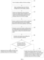
- FIG. 1 is a flowchart of the method for manufacturing the heat exchanger for supercritical pressure fluid according to the present disclosure. It is provided the method for manufacturing the heat exchanger for supercritical pressure fluid as shown in FIG. 1 , in which first working fluid is arranged in hot fluid passages of the heat exchanger for supercritical pressure fluid, and a second working fluid is arranged in cold fluid passages of the heat exchanger for supercritical pressure fluid, the method includes the following steps.
- boundary conditions of the heat exchanger for supercritical pressure fluid is received.
- the boundary conditions include first and second working fluids' parameters.
- the first working fluid parameters include an inlet temperature, an outlet temperature, a pressure and a flow of the first working fluid
- the second working fluid parameters include an inlet temperature, an outlet temperature, a pressure and a flow of the second working fluid.
- a preliminary framework of the heat exchanger is adjusted based on the boundary conditions.
- the preliminary framework of the heat exchanger includes a passage equivalent diameter, a passage length and a passage number, and arrangements of cold fluid passages and hot fluid passages of the heat exchanger.
- the step 102 specifically includes the following steps of:
- each of fluid passages is divided along a fluid flow direction and a thermal equilibrium control model is established for each divided fluid passage based on the preliminary framework of heat exchanger.
- the fluid passages include hot fluid passages and cold fluid passages, each of the fluid passages includes multiple divided fluid passages.
- the step 103 specifically includes the following operations.
- a machine heat transfer model is constructed in combination with a Gaussian regression process and a Cokriging method based on the thermal equilibrium control model.
- the step 104 specifically includes the following steps of:
- step 105 the convective heat transfer coefficients about the working fluid flowing and transferring heat in the fluid passages are determined according to the machine heat transfer model.
- the on-way thermal parameters include a fluid temperature, a fluid velocity and a pressure loss.
- step 106 the heat transfer area is determined according to the convective heat transfer coefficients.
- step 107 it is determined whether the heat transfer area meets a target heat transfer area, if yes, step 108 is performed, and if not, step 109 is performed.
- step 108 the heat exchanger for supercritical pressure fluid is manufactured according to the preliminary framework of the heat exchanger.
- step 109 the primary framework of the heat exchanger is readjusted until the heat transfer area meets the target heat transfer area, and the heat exchanger is manufactured according to the preliminary framework of the heat exchanger.
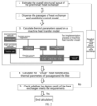
- FIG. 2 is a flowchart of a design method of the heat exchanger for supercritical pressure fluid in combination with machine learning provided by the present disclosure. As shown in FIG. 2 , the design method includes the following steps.
- the known boundary conditions for the design of the heat exchanger mainly include the inlet temperature, the pressure and the flow of the first working fluid and the inlet temperature, the outlet temperature, the pressure and the flow of the second working fluid.
- the outlet temperature of the first working fluid is calculated according to given boundary conditions and a thermal equilibrium equation.
- h h Nu 0 h ⁇ h d
- h c Nu 0 c ⁇ c d
- ⁇ 1 1 h h + ⁇ ⁇ + 1 h c
- ⁇ is a thermal conductivity of a metal plate between the cold and hot flow passages
- ⁇ is an average thickness of the plate.
- the overall framework of the heat exchanger is preliminarily obtained through the above calculations, and includes the equivalent diameter, the passage length and the passage number, the arrangements of the cold fluid passages and the hot fluid passages and the like of the heat exchanger. It is possible to carry out calculation on the thermal parameters of the local flowing working fluid along passages of the heat exchanger according to the established preliminary framework of the heat exchanger;
- each flow passage unit is divided along the fluid flow direction into n micro sections in an equal or unequal manner, and a system of thermal equilibrium equations is established for each micro section.
- q i q m _ hi c p _ hi t hi ⁇ t hi + 1
- q i q m _ ci c p _ ci t ci ⁇ t ci + 1
- q i k i A i t m _ hi ⁇ t m _ ci
- q i is a heat flux in the i-th micro section
- q m_ci and q m_hi are respectively cold and hot fluid flows
- c p_hi and c p_ci are respectively the specific heat capacities at constant pressure of the hot and cold fluid
- t m_c i and t m_hi are respectively temperatures of the second working fluid and the first working fluid at the central nodes of the i-th micro section
- a i is a heat transfer area in the i-th micro section, subscribe i represents the i-th micro section, and i+1 represents a next micro section relative to the i-th micro section.
- the implementation process mainly includes the following three aspects.
- the experimental data and numerical simulation data are collected and summarized, which generally include the on-way flow rate of the fluid, the wall surface temperature, the temperature of the main flow of the fluid, the fluid pressure, the convective heat transfer coefficient and the passage characteristic length and the like. And a set of the data is cleaned, and abnormal data, outliers and the like contained in the data set are deleted.
- the Nusselt number is a common dimensionless number in heat transfer theory, and represents an intensity of convective heat transfer in a physical sense, and the larger the value of the Nusselt number is, the stronger the intensity of convective heat transfer of fluid is, namely, the convective heat transfer performance is stronger.
- the form of the feature vector x may vary depending on the parameters contained in the data set.
- the data set includes a high-precision data set and a low-precision data set, which include values of all the parameter in the feature vector and the value of the Nusselt number Nu to be predicted finally.
- the high and low precision mainly refers to the precision of a target value, i.e., Nusselt number Nu, to be predicted finally.
- the high-precision data set refers to a data set obtained by experiment data or numerical simulation data
- the low-precision data set refers to data predicted by using the dimensionless criterion correlation equation such as the formula (2) obtained based on existing research.
- All data including the high-precision data set and the low-precision data set are randomly sampled, and then divided into a training set and a testing set which do not intersect with each other.
- the training set is used for training the machine learning model
- the testing set is used for evaluating the predictive performance of the machine learning model.
- the input parameters to the model are all parameters (i.e. the flow rate, the wall surface temperature, the temperature of the main flow of the fluid, the fluid pressure and the characteristic length) in the training set except for the convective heat transfer coefficient, and the output parameters are the convective heat transfer coefficient.
- the training is performed in an iterative manner. In each iteration, the output convective heat transfer coefficient is compared with the convective heat transfer coefficient in training set, and the iteration is performed continuously until a deviation there between is minimized, so as to obtain a substitution model for predicting the convective heat transfer coefficient of the supercritical fluid.
- substitution model There are two methods for training the substitution model, one of them uses the Gaussian regression process to construct a multi-precision substitution model and another uses the Cokriging method.
- the training process of these two substitution models is shown in FIG. 1 .
- the training set from the high-precision data set is directly adopted for training to obtain the substitute model.
- the training data set from low-precision data set firstly is used for training to obtain a Gaussian process, namely a low-precision model f ⁇ 1 ; and then, the training data set from the high-precision data set is used for training to obtain a new Gaussian process ⁇ , namely high-precision model; next, the low-precision data, the low-precision model, the high-precision data and the high-precision model are used simultaneously for training a multi-precision model through a Cokriging method; last, relevant parameters in a training result are stored.
- thermophysical property parameters of the system are transformed into a dimensionless form, so that the format and the physical meaning thereof are consistent with those of the input parameters in the training process.
- the dimensionless parameters transformed are substituted into the multi-precision substitution model trained to calculate the local convective heat transfer coefficients of the passages of the heat exchanger.
- the on-way thermal parameters about the working fluids flowing and transferring heat in the passages of the heat exchanger which mainly includes a temperature, a velocity, a pressure loss and the like, is calculated by the machine heat transfer model established in the process 3), to obtain a heat transfer area "actually" required.
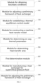
- Fig. 3 is a structural chart of a system for manufacturing the heat exchanger for supercritical pressure fluid provided by the present disclosure. It is provided a system for manufacturing a heat exchanger for supercritical pressure fluid as shown in FIG. 3 , and a first working fluid is arranged in hot fluid passages of the heat exchanger for supercritical pressure fluid, and a second working fluid is arranged in cold fluid passages of the heat exchanger for supercritical pressure fluid, the system includes a module for obtaining boundary conditions 301, a module for adjusting a preliminary frame of heat exchanger 302, a module for establishing a thermal equilibrium control model 303, a module for constructing a machine heat transfer model 304, a module for determining on-way thermal parameters 305, a module for determining heat transfer area 306, a first determination module 307, a module for manufacturing the heat exchanger for supercritical pressure fluid 308, and a module for adjusting the preliminary framework of the heat exchanger 309.
- the module 301 is configured to obtain the boundary conditions of the heat exchanger for supercritical pressure fluid, which include first and second working fluid parameters.
- the first working fluid parameters include an inlet temperature, an outlet temperature, a pressure and a flow of the first working fluid.
- the second working fluid parameters include an inlet temperature, an outlet temperature, a pressure and a flow of the second working fluid.
- the module 302 is configured to adjust a preliminary framework of the heat exchanger based on the boundary conditions.
- the preliminary framework of the heat exchanger includes a equivalent diameter, a length and a number of passages, and arrangements of cold fluid passages and hot fluid passages of the heat exchanger.
- the module 302 specifically includes: an unit for determining an average Nusselt number, configured for determining the average Nusselt number according to the first and the second working fluid parameters; an unit for determining the equivalent diameter of passages, configured for determining a first average convective heat transfer coefficient of the first working fluid and a second average convective heat transfer coefficient of the second working fluid respectively and determining the equivalent diameter of passages according to the average Nusselt number; an unit for determining a total heat transfer coefficient, configured for determining the total heat transfer coefficient according to the first average convective heat transfer coefficient and the second average convective heat transfer coefficient; an unit for determining a heat exchange quantity, configured for determining the heat transfer quantity according to the total heat transfer coefficient; an unit for determining the length and the number of passages, configured for determining the passage length and the passage number according to the heat transfer quantity; an unit for determining the arrangements of cold fluid passages and hot fluid passages, configured for determining the arrangements of cold fluid passages and hot fluid passages according to the passage length and the passage
- the module 303 is configured to divide each fluid passage along a fluid flow direction and establishing a thermal equilibrium control model for each divided fluid passage based on the preliminary framework of the heat exchanger.
- the fluid passages include hot fluid passages and cold fluid passages; one of the fluid passages includes a plurality of divided fluid passages.
- the module 303 specifically includes a unit for establishing the thermal equilibrium control model, configured for establishing the thermal equilibrium control model.
- the module 304 is configured to construct a machine heat transfer model in combination with a Gaussian regression process and a Cokriging method based on the thermal equilibrium control model.
- the module 304 specifically includes a module for obtaining heat transfer data of the supercritical pressure fluid, a preprocessing module, a module for determining a low-precision model, a module for determining a high-precision model, a module for determining a multi-precision model.
- the module for obtaining heat transfer data of the supercritical pressure fluid is configured for obtaining the heat transfer data of the supercritical pressure fluid.
- the heat transfer data of the supercritical pressure fluid include high-precision and low-precision heat transfer data.
- the high-precision heat transfer data are a data set obtained from experiment or numerical simulation data
- the low-precision heat transfer data are a data set predicted by a dimensionless criterion correlation equation.
- the heat transfer data of the supercritical pressure fluid are an on-way flow rate of the fluid, a wall surface temperature, a temperature of a main flow of the fluid, a fluid pressure, a convective heat transfer coefficient and the passage characteristic length.
- the preprocessing module is configured for preprocessing the heat transfer data of the supercritical pressure fluid, and determining the preprocessed heat transfer data of supercritical pressure fluid.
- the preprocessed heat transfer data of the supercritical pressure fluid includes preprocessed low-precision and preprocessed high-precision heat transfer data.
- the module for determining a low-precision model is configured for determining the low-precision model according to the preprocessed low-precision heat transfer data based on the Gaussian regression equation.
- the module for determining a high-precision model is configured for determining a high-precision model according to the preprocessed high-precision heat transfer data based on the Gaussian regression equation.
- the module for determining a multi-precision model is configured for determining the multi-precision model according to the low-precision heat transfer data, the low-precision model, the high-precision heat transfer data and the high-precision model by utilizing the Cokriging method based on the thermal equilibrium control model.
- the multi-precision model is a machine heat transfer model which takes dimensionless parameters of screened heat transfer data of the supercritical pressure fluid as an input and takes the convective heat transfer coefficient as an output.
- the screened heat transfer data of the supercritical pressure fluid include the on-way flow rate of the fluid, the wall surface temperature, the temperature of the main flow of the fluid, the fluid pressure, the convective heat transfer coefficient and the passage characteristic length.
- the machine heat transfer model is used for determining the on-way thermal parameters about the working fluids flowing and transferring heat in the fluid passages.
- ⁇ ⁇ 2 X is the high-precision model
- ⁇ ( X ) is a scale factor for characterizing a quantitative relationship between output values of two precision model
- ⁇ ⁇ 1 X is the low-precision model
- ⁇ ( X ) is the Gaussian process.
- the module 305 is configured for determining the on-way thermal parameters of about the working fluids flowing and transferring heat in the fluid passages according to the machine heat transfer model.
- the on-way thermal parameters include a fluid temperature, a fluid velocity and a pressure loss.
- the module 306 is configured for determining the heat transfer area according to the on-way thermal parameters.
- the first determination module 307 is configured for determining whether the heat transfer area meets a target heat transfer area to obtain a first determination result.
- the module 308 is configured for manufacturing the heat exchanger for supercritical pressure fluid according to the preliminary framework of the heat exchanger if the first determination result indicates that the heat transfer area meets the target heat transfer area.
- the module 309 is configured for readjusting the primary framework of the heat exchanger until the heat transfer area meets the target heat transfer area if the first determination result indicates that the heat transfer area fails to meet the target heat transfer area standard.
- the machine heat transfer model established by the disclosure simultaneously employs high-precision data directly from numerical simulation for the supercritical pressure fluid, data calculated by utilizing criterion correlation equation of convection heat transfer and limited experimental data, and the prediction precision of the machine heat transfer model is higher, and particularly, the machine heat transfer model can provide more high-precision prediction for some extreme and unsteady heat transfer working conditions of the supercritical pressure fluid.
- the method for constructing the heat transfer machine model according to the disclosure can not only obtain the heat transfer coefficient of the supercritical pressure fluid with a higher precision than that of a heat transfer criterion correlation equation, but also itself has good generalization performance and stronger maneuverability.
- the model itself can be continuously improved in respect of the prediction precision by employing more and higher-precision data, and thus is healthily growing.
- the disclosure trains a machine learning substitution model for heat transfer coefficient by means of the Gaussian process regression and Cokriging method in the machine learning technology and in combination with high-precision data from experiments and low-precision data predicted by the correlation equation.
- the substitution model is applied in the calculation process of the discrete iterative design about a heat exchanger as a substitution of the traditional method of designing the heat exchanger by using the empirical correlation equation, to quickly and accurately predict the on-way thermal parameters of the working fluid in the passages of heat exchanger, and eventually obtain a design solution of heat exchanger with higher comprehensive performance in respect of flow heat transfer.
Landscapes
- Engineering & Computer Science (AREA)
- Physics & Mathematics (AREA)
- General Physics & Mathematics (AREA)
- Theoretical Computer Science (AREA)
- General Engineering & Computer Science (AREA)
- Mathematical Analysis (AREA)
- Data Mining & Analysis (AREA)
- Pure & Applied Mathematics (AREA)
- Mathematical Optimization (AREA)
- Mathematical Physics (AREA)
- Evolutionary Computation (AREA)
- Computational Mathematics (AREA)
- Algebra (AREA)
- Geometry (AREA)
- Software Systems (AREA)
- Computer Hardware Design (AREA)
- Life Sciences & Earth Sciences (AREA)
- Databases & Information Systems (AREA)
- Evolutionary Biology (AREA)
- Bioinformatics & Computational Biology (AREA)
- Computing Systems (AREA)
- Fluid Mechanics (AREA)
- Operations Research (AREA)
- Bioinformatics & Cheminformatics (AREA)
- Probability & Statistics with Applications (AREA)
- Artificial Intelligence (AREA)
- Computer Vision & Pattern Recognition (AREA)
- Medical Informatics (AREA)
- Thermal Sciences (AREA)
- Mechanical Engineering (AREA)
- Health & Medical Sciences (AREA)
- Automation & Control Theory (AREA)
- Separation By Low-Temperature Treatments (AREA)
- Management, Administration, Business Operations System, And Electronic Commerce (AREA)
Description
- The disclosure relates to the field of manufacture of a heat exchanger for supercritical pressure fluid, and in particular to a method and a system for manufacturing a heat exchanger for supercritical pressure fluid.
- The supercritical CO2 Brayton cycle is a Brayton cycle with CO2 at a supercritical pressure as a working fluid. Compared with traditional cycles, it has the advantages of low power consumption in compression, high overall efficiency and compact structure. The CO2 at supercritical pressure as a main working fluid has the characteristics of high density, low viscosity, strong diffusivity and permeability and the like, so the supercritical CO2 Brayton cycle has wide development prospects in the fields of aero engines, fourth generation nuclear reactors, solar thermal power and the like. Since CO2 at an inlet of a compressor during the cycle is close to a critical state, the convection heat transfer rule is very complex due to significantly variable physical properties of the CO2, and thereby, it is necessary to study the internal flow and heat transfer rule of the heat exchanger.
- In the document of LI XU ET AL: "A cooperative radial basis function method for variable-fidelity surrogate modeling", STRUCTURAL AND MULTDISCIPLINARY OPTIMIZATION, SPRINGER BERLIN HEIDELBERG, BERLIN/HEIDELBERG, vol. 56, no. 5, 15 May 2017 (2017-05-15), pages 1077-1092, a cooperative radial basis function (Co-RBF) method for the variable-fidelity model (VFM) is proposed by modifying the basis function of RBF. The RBF method is constructed on the high-fidelity (HF) samples, while the Co-RBF method incorporates the entire information of the low-fidelity (LF) model with the HF samples. In Co-RBF and the HF samples are utilized to compute the Co-RBF model coefficients. Two numerical functions and three engineering problems are adopted to verify the proposed Co-RBF are compared with those of RBF and Co-Kriging, which show that the Co-RBF method improves the efficiency, accuracy and robustness of the existing VFMs.
-
CN 109508854A discloses a method for evaluate that comprehensive performance of a supercritical carbon dioxide cycle power generation system of a small lead-based reactor. Firstly, the basic operating parameters of the supercritical carbon dioxide (S-CO2) cycle power generation system for lead-based reactor are determined. Subsequently, the modular design method is used to establish the sub-modules of turbomachinery work, heat transfer, heat exchanger pressure drop calculation, heat exchanger efficiency calculation, thermal analysis and economic analysis of power generation system. Then the iterative calculation method is used to solve the heat exchanger pressure drop calculation and the thermodynamic analysis sub-module of the power generation system, and the thermal performance of power generation system is evaluated. - In the Document of YANG XIU ET AL: "Physics-informed CoKriging: A Gaussian-process-regression-based multifidelity method for data-model convergence", JOURNAL OF COMPUTATIONAL PHYSICS, LONDON, GB, vol. 395, 19 June 2019 (2019-06-19), pages 410-431, a new Gaussian process regression (GPR)-based multifidelity method: physics-informed CoKriging (CoPhlK) is proposed. In CoKriging-based multifidelity methods, the quantities of interest are modeled as linear combinations of multiple parameterized stationary Gaussian processes (GPs), and the hyperparameters of these GPs are estimated from data via optimization. In GoPhIK, a GP representing low-fidelity data using physics-informed Kriging (PhIK) is constructed, the discrepancy between low- and high-fidelity data using a parameterized GP with hyperparameters identified via optimization is modelled.
- In the document of ELSAYED KHAIRY ED - SALMAN AGBA D ET AL: "Optimization of the cyclone separator geometry for minimum pressure drop using Co-Kriging", POWDER TECHNOLOGY, ELSEVIER, BASEL (CH), vol. 269, 28 September 2014 (2014-09-28), pages 409-424, five approaches are proposed and tested for sampling update for the Co-Kriging. These approaches succeeded to enhance the model accuracy by adding few points from both the low-fidelity and high-fidelity simulations. The Co-Kriging model has been used to get a new optimized cyclone for minimum pressure drop using the genetic algorithms optimization technique. A CFD comparison between the new design and the standard Stairmand design has been performed.
- In the document of KAYABASI E ET AL: "Simulation of heat exchangers and heat exchanger networks with an economic aspect", ENGINEERING SCIENCE AND TECHNOLOGY, AN INTERNATIONAL JOURNAL, vol. 21, no. 1, 1 February 2018 (2018-02-01), pages 70-76, relations between effectiveness and expense coefficients were derived, and an economic simulation model was developed to simulate heat exchangers (HE) and HE networks (HEN) in all flow types for the first time. Effectiveness values of parallel flow, counter flow, cross flow and all HEs under the condition of Cr=0 were derived in terms of the expense coefficients NTU (Number of Transfer Unit) and minimum heat capacities. The effectiveness values obtained from economic calculations were used for developing economic simulation model of HEs. Vectors including outlet temperatures and inlet temperatures of flows were obtained from static simulation to utilize in economic simulation model. Then, case studies were performed with counter flow HE and effectiveness values randomly determined in a sample HEN.
- A type of heat exchanger possibly used for the supercritical CO2 brayton cycle is a printed circuit heat exchanger (PCHE). The PCHE is manufactured by engraving grooves on metal substrates as cold and hot fluid flow passages, and then stacking cold and hot substrates alternately and welding these substrates through a diffusion bonding technology. Compared with the traditional heat exchangers, the PCHE has the advantages of better strength and integrity, and withstanding harsh conditions such as high temperature, high pressure, and large temperature difference.
- At present, a more common design calculation method of PCHE is an overall design method based on inlet and outlet parameters of a heat exchanger with a logarithmic mean temperature difference method. Such method mainly includes: after determining a flow form of the heat exchanger, determining a fourth temperature value according to thermal equilibrium based on given heat transfer quantity and three temperatures of inlet and outlet temperatures at a cold side and a hot side of the heat exchanger, and calculating the logarithmic mean temperature difference. Assuming that the average values of the inlet and outlet temperatures are respectively temperature values of a fluid at the cold side and the hot side, an average Nusselt number and a heat transfer coefficient are calculated by using a correlation equation, and thereby structural parameters such as a heat transfer area, a passage length of the heat exchanger are determined after determining average physical parameters. The result designed by adopting the overall design method based on the average values of the inlet and outlet parameters is often rough, and is difficult to reflect the local convective heat transfer performance in the flow passages.
- In order to solve the problem, areas of flow passages of the heat exchanger to be calculated can be discretized, and processes of calculation and iteration similar to the average method can be carried out on the areas discretized to obtain local convective heat transfer coefficients along the passages. However, on the one hand, a result obtained by using the correlation equation without considering changes in physical properties often has a low precision due to the variable physical properties of the supercritical pressure fluid. On the other hand, as the size of the passages in the heat exchanger is reduced, the influence of a heat acceleration phenomenon on the heat transfer is significantly increased, and in this case a prediction precision of the existing correlation is reduced, so that the precision and the reliability of the calculated result is greatly influenced. In addition, for complex working conditions, it often requires 100 or more data points to construct the correlation equation, and it is difficult to obtain a large number of high-precision data points, and the cost is also very high.
- The embodiments aim to provide a method and a system for manufacturing a heat exchanger for supercritical pressure fluid to solve the difficulties of obtaining a large number of high-precision data points to construct a correlation equation in the existing manufacturing process of a heat exchanger for supercritical pressure fluid, which causes some problems, such as, the precision of structural parameters of predicted heat exchanger is low, and thus the manufactured heat exchanger is poor in performance.
- In order to achieve the above object, the disclosure provides the following solutions.
- It is provided a method for manufacturing a heat exchanger for supercritical pressure fluid, which has a first working fluid arranged in hot fluid passages of the heat exchanger and a second working fluid arranged in cold fluid passages of the heat exchanger. The method includes the following steps of:
- obtaining boundary conditions of the heat exchanger; the boundary conditions including first working fluid parameters and second working fluid parameters, the first working fluid parameters including an inlet temperature, an outlet temperature, a pressure and a flow of the first working fluid, the second working fluid parameters including an inlet temperature, an outlet temperature, a pressure and a flow of the second working fluid;
- adjusting a preliminary framework of the heat exchanger based on the boundary conditions, the preliminary framework of the heat exchanger including a passage equivalent diameter, a passage length, a passage number, and arrangements of cold fluid passages and hot fluid passages of the heat exchanger;
- dividing each of fluid passages along a fluid flow direction and establishing a thermal equilibrium control model for each divided fluid passage based on the preliminary framework of the heat exchanger, the fluid passages including hot fluid passages and cold fluid passages, each of the fluid passages including a plurality of the divided fluid passages;
- constructing a machine heat transfer model in combination with a Gaussian regression process and a Cokriging method based on the thermal equilibrium control model;
- determining convective heat transfer coefficients about the working fluids flowing and transferring heat in the fluid passages according to the machine heat transfer model, the on-way thermal parameters including a fluid temperature, a fluid velocity and a pressure loss;
- determining a heat transfer area according to the convective heat transfer coefficients;
- determining whether the heat transfer area meets a target heat transfer area to obtain a first determination result:
- manufacturing the heat exchanger according to the preliminary framework of the heat exchanger, when the first determination result indicates that the heat transfer area meets the target heat transfer area;
- readjusting the preliminary framework of the heat exchanger for repeating the above steps until the heat transfer area meets the target heat transfer area, if the first determination result indicates that the heat transfer area fails to meet the target heat transfer area; and manufacturing the heat exchanger according to a readjusted preliminary framework of the heat exchanger.
- In some embodiments, the adjusting a preliminary framework of the heat exchanger based on the boundary conditions specifically includes:
- determining an average Nusselt number according to the first working fluid parameters and the second working fluid parameters;
- determining a first average convective heat transfer coefficient of the first working fluid and a second average convective heat transfer coefficient of the second working fluid respectively and determining the passage equivalent diameter according to the average Nusselt number;
- determining a total heat transfer coefficient according to the first average convective heat transfer coefficient and the second average convective heat transfer coefficient;
- determining a heat transfer quantity according to the total heat transfer coefficient;
- determining the passage length and the passage number according to the heat transfer quantity;
- determining the arrangements of cold fluid passages and hot fluid passages according to the passage length and the passage number;
- determining the preliminary framework of the heat exchanger according to passage equivalent diameter, passage length, passage number, and the arrangements of cold fluid passages and hot fluid passages.
- In some embodiments, the dividing each of fluid passages along a fluid flow direction and establishing a thermal equilibrium control model for each divided fluid passage based on the preliminary framework of the heat exchanger specifically includes:
the thermal equilibrium control model being as follows:


- In some embodiments, the constructing a machine heat transfer model in combination with a Gaussian regression process and a Cokriging method based on the thermal equilibrium control model specifically includes:
- obtaining heat transfer data of the supercritical pressure fluid, the heat transfer data of the supercritical pressure fluid including second precision and first precision heat transfer data, the second precision heat transfer data being a data set obtained from experiment or numerical simulation data, the first precision heat transfer data being a data set predicted by dimensionless criterion correlation equation, the heat transfer data of the supercritical pressure fluid being an on-way flow rate of the fluid, a wall surface temperature, a temperature of a main flow of the fluid, a fluid pressure, a convective heat transfer coefficient and a passage characteristic length;
- preprocessing the heat transfer data of the supercritical pressure fluid, and determining preprocessed heat transfer data of the supercritical pressure fluid, the preprocessed heat transfer data of the supercritical pressure fluid including preprocessed first precision and preprocessed second precision heat transfer data;
- determining a first precision model according to the preprocessed first precision heat transfer data based on a Gaussian regression equation;
- determining a second precision model according to the preprocessed second precision heat transfer data based on the Gaussian regression equation;
- determining a multi-precision model according to the first precision heat transfer data, the first precision model, the second precision heat transfer data and the second precision model by utilizing a Cokriging method based on the thermal equilibrium control model, the multi-precision model being a machine heat transfer model which takes dimensionless parameters of screened heat transfer data of the supercritical pressure fluid as an input and takes the convective heat transfer coefficient as an output, the screened heat transfer data of the supercritical pressure fluid including the on-way flow rate of the fluid, the wall surface temperature, main flow temperature of the fluid, fluid pressure, convective heat transfer coefficient and the passage characteristic length, the machine heat transfer model being used for determining on-way thermal parameters about the working fluids flowing and transferring heat in the fluid passages.
- In some embodiments, the determining a multi-precision model according to the first precision heat transfer data, the first precision model, the second precision heat transfer data and the second precision model by utilizing a Cokriging method specifically includes:
- dividing the second precision heat transfer data into a training set and a testing set;
- determining a multi-precision model according to a formula:


- A system for manufacturing a heat exchanger for supercritical pressure fluid, which has a first working fluid arranged in hot fluid passages of the heat exchanger and a second working fluid arranged in cold fluid passages of the heat exchanger, the system includes:
- a module for obtaining boundary conditions, configured for receiving the boundary conditions of the heat exchanger, the boundary conditions including first and second working fluid parameters, the first working fluid parameters including an inlet temperature, an outlet temperature, a pressure and a flow of the first working fluid; the second working fluid parameters including an inlet temperature, an outlet temperature, a pressure and a flow of the second working fluid;
- a module for adjusting a preliminary framework of the heat exchanger, configured for adjusting the preliminary framework of the heat exchanger based on the boundary conditions, the preliminary framework of the heat exchanger including a passage equivalent diameter, a passage length, a passage number, and arrangements of cold fluid passages and hot fluid passages of the heat exchanger;
- a module for establishing a thermal equilibrium control model, configured for dividing each of fluid passages along a fluid flow direction and establishing the thermal equilibrium control model for each divided fluid passage based on the preliminary framework of the heat exchanger, the fluid passages including hot fluid passages and cold fluid passages, each of the fluid passages including a plurality of the divided fluid passages;
- a module for constructing a machine heat transfer model, configured for constructing the machine heat transfer model in combination with a Gaussian regression process and a Cokriging method based on the thermal equilibrium control model;
- a module for determining on-way thermal parameters, configured for determining convective heat transfer coefficients about the working fluids flowing and transferring heat in the fluid passages according to the machine heat transfer model, the on-way thermal parameters including a fluid temperature, a fluid velocity and a pressure loss;
- a module for determining a heat transfer area, configured for determining the heat transfer area according to the convective heat transfer coefficients;
- a first determination module, configured for determining whether the heat transfer area meets a target heat transfer area, to obtain a first determination result;
- a module for manufacturing the heat exchanger, configured for instructing to manufacture the heat exchanger according to the preliminary framework of the heat exchanger, if the first determination result indicates that the heat transfer area meets the target heat transfer area; and
- a module for adjusting the preliminary framework of the heat exchanger, configured for readjusting the preliminary framework of the heat exchanger for repeating the above steps until the heat transfer area meets the target heat transfer area, if the first determination result indicates that the heat transfer area fails to meet the target heat transfer area and instructing to manufacturing the heat exchanger according to a readjusted preliminary framework of the heat exchanger.
- In some embodiments, the module for adjusting the preliminary framework of the heat exchanger specifically includes:
- a unit for determining an average Nusselt number, configured for determining an average Nusselt number according to the first and the second working fluid parameters;
- a unit for determining a passage equivalent diameter, configured for determining a first average convective heat transfer coefficient of the first working fluid and a second average convective heat transfer coefficient of the second working fluid respectively and determining the passage equivalent diameter according to the average Nusselt number;
- a unit for determining a total heat transfer coefficient, configured for determining the total heat transfer coefficient according to the first average convective heat transfer coefficient and the second average convective heat transfer coefficient;
- a unit for determining a heat transfer quantity, configured for determining the heat transfer quantity according to the total heat transfer coefficient;
- a unit for determining the passage length and the passage number, used for determining the passage length and the passage number according to the heat transfer quantity;
- a unit for determining the arrangements of cold fluid passages and hot fluid passages, configured for determining the arrangements of cold fluid passages and hot fluid passages according to the passage length and the passage number;
- a unit for determining a preliminary framework of the heat exchanger, configured for determining a preliminary framework of the heat exchanger according to the passage equivalent diameter, the passage length, the passage number, and the arrangements of cold fluid passages and hot fluid passages.
- In some embodiments, the module for establishing the thermal equilibrium control model specifically includes:
a unit for establishing a thermal equilibrium control model, configured for establishing a thermal equilibrium control model, and the thermal equilibrium control model being as follows:


- In some embodiments, the module for constructing the machine heat transfer model specifically includes:
- a module for obtaining heat transfer data of the supercritical pressure fluid, configured for obtaining the heat transfer data of the supercritical pressure fluid, the heat transfer data of the supercritical pressure fluid including second precision and first precision heat transfer data, the second precision heat transfer data being a data set obtained from experiment or numerical simulation data; the first precision heat transfer data being a data set predicted by dimensionless criterion correlation equation, the heat transfer data of the supercritical pressure fluid being an on-way flow rate of the fluid, a wall surface temperature, a temperature of a main flow of the fluid, a fluid pressure, a convective heat transfer coefficient and a passage characteristic length;
- a preprocessing module, configured for preprocessing the heat transfer data of the supercritical pressure fluid, and determining preprocessed heat transfer data of the supercritical pressure fluid, the preprocessed heat transfer data of the supercritical pressure fluid including preprocessed first precision and preprocessed second precision heat transfer data;
- a module for determining a low-precision model, configured for determining the first precision model according to the preprocessed first precision heat transfer data based on a Gaussian regression equation;
- a module for determining a high-precision model, configured for determining the second precision model according to the preprocessed second precision heat transfer data based on the Gaussian regression equation; where the first precision heat transfer data has a lower precision than that of the second precision heat transfer data;
- a module for determining a multi-precision model, configured for determining a multi-precision model according to the first precision heat transfer data, the first precision model, the second precision heat transfer data and the second precision model by utilizing a Cokriging method based on the thermal equilibrium control model, the multi-precision model being a machine heat transfer model which takes dimensionless parameters of screened heat transfer data of the supercritical pressure fluid as an input and takes the convective heat transfer coefficient as output, the screened heat transfer data of the supercritical pressure fluid including the on-way flow rate of the fluid, the wall surface temperature, the temperature of the main flow of the fluid, the fluid pressure, the convective heat transfer coefficient and the passage characteristic length, the machine heat transfer model being used for determining on-way thermal parameters about the working fluids flowing and transferring heat in the fluid passages.
- In some embodiments, the module for determining the multi-precision model specifically includes:
- a dividing unit, configured for dividing the second precision heat transfer data into a training set and a testing set;
- an unit for determining the multi-precision model, configured for determining the multi-precision model according to a formula:


- According to the specific embodiments provided by the disclosure, the disclosure has the following technical effects. The disclosure provides a method and a system for manufacturing a heat exchanger for supercritical pressure fluid, which determine a preliminary framework of the heat exchanger according to given boundary conditions of the heat exchanger, and construct a machine heat transfer model in combination with a Gaussian regression process and a Cokriging method, and continuously adjust the preliminary framework of the heat exchanger in an iterative manner by utilizing the machine heat transfer model instead of the existing correlation equation, enabling the finally determined heat transfer area meet a target heat transfer area, and then manufacture the heat exchanger by utilizing the adjusted preliminary framework of the heat exchanger, without a large number of high-precision data points, so as to improve the heat transfer performance of the heat exchanger.
- In order to more clearly illustrate the embodiments of the disclosure or the technical solutions in the conventional art, the drawings used in the embodiments will be briefly described below, it is apparent that the drawings in the following description are only some embodiments of the disclosure, for those skilled in the art, other drawings can be obtained according to the drawings without inventive labors.
-
FIG. 1 is a flowchart of a method for manufacturing a heat exchanger for supercritical pressure fluid according to the present disclosure; -
FIG. 2 is a flowchart of a design method of the heat exchanger for supercritical pressure fluid in combination with machine learning provided by the present disclosure; and -
Fig. 3 is a structural chart of a system for manufacturing the heat exchanger for supercritical pressure fluid provided by the present disclosure. - The technical solutions in the embodiments of the present disclosure will be clearly and completely described below combining with the accompanying drawings in the embodiments of the present disclosure, and it is apparent that embodiments described are only a part of embodiments of the present disclosure, and not all of them. All other embodiments, which are obtained by a person skilled in the art based on the embodiments of the present disclosure without inventive labors, shall fall within the protection scope of the present disclosure.
- The disclosure aims to provide a method and a system for manufacturing a heat exchanger for supercritical pressure fluid, which can improve a performance of the heat exchanger for supercritical pressure fluid.
- In order to make the above purposes, features and advantages of the present disclosure more comprehensible, the present disclosure is further and detailedly described combining with the accompanying drawings and specific embodiments thereof.
-
FIG. 1 is a flowchart of the method for manufacturing the heat exchanger for supercritical pressure fluid according to the present disclosure. It is provided the method for manufacturing the heat exchanger for supercritical pressure fluid as shown inFIG. 1 , in which first working fluid is arranged in hot fluid passages of the heat exchanger for supercritical pressure fluid, and a second working fluid is arranged in cold fluid passages of the heat exchanger for supercritical pressure fluid, the method includes the following steps. - In
step 101, boundary conditions of the heat exchanger for supercritical pressure fluid is received. The boundary conditions include first and second working fluids' parameters. The first working fluid parameters include an inlet temperature, an outlet temperature, a pressure and a flow of the first working fluid, and the second working fluid parameters include an inlet temperature, an outlet temperature, a pressure and a flow of the second working fluid. - In
step 102, a preliminary framework of the heat exchanger is adjusted based on the boundary conditions. The preliminary framework of the heat exchanger includes a passage equivalent diameter, a passage length and a passage number, and arrangements of cold fluid passages and hot fluid passages of the heat exchanger. - The
step 102 specifically includes the following steps of: - determining an average Nusselt number according to the first and the second working fluid parameters;
- determining a first average convective heat transfer coefficient of the first working fluid and a second average convective heat transfer coefficient of the second working fluid respectively and determining the passage equivalent diameter according to the average Nusselt number;
- determining a total heat transfer coefficient according to the first average convective heat transfer coefficient and the second average convective heat transfer coefficient;
- determining a quantity of transferred heat according to the total heat transfer coefficient;
- determining the passage length and the passage number according to the quantity of transferred heat;
- determining the arrangements of cold fluid passages and hot fluid passages according to the passage length and the passage number; and
- determining the preliminary framework of the heat exchanger according to the passage equivalent diameter, the passage length, the passage number, and the arrangements of cold fluid passages and hot fluid passages.
- In
step 103, each of fluid passages is divided along a fluid flow direction and a thermal equilibrium control model is established for each divided fluid passage based on the preliminary framework of heat exchanger. The fluid passages include hot fluid passages and cold fluid passages, each of the fluid passages includes multiple divided fluid passages. - The
step 103 specifically includes the following operations. The thermal equilibrium control model is as follows:


- In
step 104, a machine heat transfer model is constructed in combination with a Gaussian regression process and a Cokriging method based on the thermal equilibrium control model. - The
step 104 specifically includes the following steps of: - obtaining heat transfer data of the supercritical pressure fluid, the heat transfer data of the supercritical pressure fluid include high-precision and low-precision heat transfer data, the high-precision heat transfer data are a data set obtained by data from experiment or numerical simulation; the low-precision heat transfer data are a data set predicted by dimensionless criterion correlation equation, the heat transfer data of the supercritical pressure fluid are an on-way flow rate of the fluid, a wall surface temperature, a main flow temperature of the fluid, a fluid pressure, a convective heat transfer coefficient and a passage characteristic length;
- preprocessing the heat transfer data of the supercritical pressure fluid, and determining preprocessed heat transfer data of the supercritical pressure fluid, the preprocessed heat transfer data of the supercritical pressure fluid include preprocessed low-precision and preprocessed high-precision heat transfer data;
- determining a low-precision model according to the preprocessed low-precision heat transfer data based on a Gaussian regression equation;
- determining a high-precision model according to the preprocessed high-precision heat transfer data based on the Gaussian regression equation;
- determining a multi-precision model according to the low-precision heat transfer data, the low-precision model, the high-precision heat transfer data and the high-precision model by utilizing the Cokriging method based on the thermal equilibrium control model, the multi-precision model is a machine heat transfer model which takes dimensionless parameters of screened heat transfer data of the supercritical pressure fluid as an input and takes the convective heat transfer coefficient as an output, the screened heat transfer data of the supercritical pressure fluid include the on-way flow rate of the fluid, the wall surface temperature, the main flow temperature of the fluid, the fluid pressure, and the passage characteristic length, the machine heat transfer model is used for determining on-way thermal parameters about the working fluids flowing and transferring heat in the fluid passages.
- The determining a multi-precision model according to the low-precision heat transfer data, the low-precision model, the high-precision heat transfer data and the high-precision model by utilizing the Cokriging method specifically includes: dividing the high-precision heat transfer data into a training set and a testing set; determining the multi-precision model according to a formula:

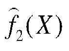

- In
step 105, the convective heat transfer coefficients about the working fluid flowing and transferring heat in the fluid passages are determined according to the machine heat transfer model. The on-way thermal parameters include a fluid temperature, a fluid velocity and a pressure loss. - In
step 106, the heat transfer area is determined according to the convective heat transfer coefficients. - In
step 107, it is determined whether the heat transfer area meets a target heat transfer area, if yes, step 108 is performed, and if not, step 109 is performed. - In
step 108, the heat exchanger for supercritical pressure fluid is manufactured according to the preliminary framework of the heat exchanger. - In
step 109, the primary framework of the heat exchanger is readjusted until the heat transfer area meets the target heat transfer area, and the heat exchanger is manufactured according to the preliminary framework of the heat exchanger. - In practical application,
FIG. 2 is a flowchart of a design method of the heat exchanger for supercritical pressure fluid in combination with machine learning provided by the present disclosure. As shown inFIG. 2 , the design method includes the following steps. - The known boundary conditions for the design of the heat exchanger mainly include the inlet temperature, the pressure and the flow of the first working fluid and the inlet temperature, the outlet temperature, the pressure and the flow of the second working fluid. Firstly, the outlet temperature of the first working fluid is calculated according to given boundary conditions and a thermal equilibrium equation. Secondly, a logarithmic mean temperature difference is calculated by a following expression according to the inlet and outlet temperatures of the first working fluid and the second working fluid,

- Via the inlet and outlet temperatures and pressure information of the working fluids at the two sides of the heat exchanger, physical property parameters of the working fluids at qualitative temperature, such as density ρ, dynamic viscosity µ, thermal conductivity λ, are determined, and criterion numbers such as an average Reynolds number Reb of the main flow and a Prandtl Number Pr are calculated. The average Nusselt number Nu0 is calculated by the following criteria correlation equation:

- After the average Nusselt number is obtained, the average convective heat transfer coefficients of working fluids in the passages at two sides of the heat transfer unit are calculated:


- The total heat transfer area A is calculated according to the heat transfer amount q and the heat flux, and a per unit flow passage length L is calculated according to the number of the flow passages N and a per unit heat transfer surface area of flow passage:


- The overall framework of the heat exchanger is preliminarily obtained through the above calculations, and includes the equivalent diameter, the passage length and the passage number, the arrangements of the cold fluid passages and the hot fluid passages and the like of the heat exchanger. It is possible to carry out calculation on the thermal parameters of the local flowing working fluid along passages of the heat exchanger according to the established preliminary framework of the heat exchanger;
- According to the preliminary framework of the heat exchanger obtained in the process 1), each flow passage unit is divided along the fluid flow direction into n micro sections in an equal or unequal manner, and a system of thermal equilibrium equations is established for each micro section.


- In the above formulas, qi is a heat flux in the i-th micro section; qm_ci and qm_hi are respectively cold and hot fluid flows; cp_hi and cp_ci are respectively the specific heat capacities at constant pressure of the hot and cold fluid; t m_ci and tm_hi are respectively temperatures of the second working fluid and the first working fluid at the central nodes of the i-th micro section; Ai is a heat transfer area in the i-th micro section, subscribe i represents the i-th micro section, and i+1 represents a next micro section relative to the i-th micro section.
- The implementation process mainly includes the following three aspects.
- The experimental data and numerical simulation data are collected and summarized, which generally include the on-way flow rate of the fluid, the wall surface temperature, the temperature of the main flow of the fluid, the fluid pressure, the convective heat transfer coefficient and the passage characteristic length and the like. And a set of the data is cleaned, and abnormal data, outliers and the like contained in the data set are deleted.
- The Nusselt number is a common dimensionless number in heat transfer theory, and represents an intensity of convective heat transfer in a physical sense, and the larger the value of the Nusselt number is, the stronger the intensity of convective heat transfer of fluid is, namely, the convective heat transfer performance is stronger. In general, it can be assumed that the Nusselt number is a function of a series of characteristic parameters and a vector including these characteristic parameters is x, then:

- The form of the feature vector x may vary depending on the parameters contained in the data set. In the present disclosure, the Reynolds number Re, Prandtl Number Pr, Bo* number, the ratio of physical properties calculated in the preprocessing step, and the dimensionless position corresponding to the parameter in the passage will be used as the characteristic parameters during prediction, that is,

- The data set includes a high-precision data set and a low-precision data set, which include values of all the parameter in the feature vector and the value of the Nusselt number Nu to be predicted finally. The high and low precision mainly refers to the precision of a target value, i.e., Nusselt number Nu, to be predicted finally. The high-precision data set refers to a data set obtained by experiment data or numerical simulation data, and the low-precision data set refers to data predicted by using the dimensionless criterion correlation equation such as the formula (2) obtained based on existing research.
- ② Constructing a machine learning algorithm in combination with the Gaussian regression process and the Cokriging method, and training a multi-precision substitution model by using the existing data.
- All data including the high-precision data set and the low-precision data set are randomly sampled, and then divided into a training set and a testing set which do not intersect with each other. The training set is used for training the machine learning model, and the testing set is used for evaluating the predictive performance of the machine learning model.
- In the training process, the input parameters to the model are all parameters (i.e. the flow rate, the wall surface temperature, the temperature of the main flow of the fluid, the fluid pressure and the characteristic length) in the training set except for the convective heat transfer coefficient, and the output parameters are the convective heat transfer coefficient. The training is performed in an iterative manner. In each iteration, the output convective heat transfer coefficient is compared with the convective heat transfer coefficient in training set, and the iteration is performed continuously until a deviation there between is minimized, so as to obtain a substitution model for predicting the convective heat transfer coefficient of the supercritical fluid. There are two methods for training the substitution model, one of them uses the Gaussian regression process to construct a multi-precision substitution model and another uses the Cokriging method. The training process of these two substitution models is shown in
FIG. 1 . Specifically, in the training process by the gaussian regression process, the training set from the high-precision data set is directly adopted for training to obtain the substitute model. In the training process by the Cokriging method, the training data set from low-precision data set firstly is used for training to obtain a Gaussian process, namely a low-precision model f̂ 1 ; and then, the training data set from the high-precision data set is used for training to obtain a new Gaussian process δ, namely high-precision model; next, the low-precision data, the low-precision model, the high-precision data and the high-precision model are used simultaneously for training a multi-precision model through a Cokriging method; last, relevant parameters in a training result are stored. - Similar to the data preprocessing step, the on-way thermophysical property parameters of the system are transformed into a dimensionless form, so that the format and the physical meaning thereof are consistent with those of the input parameters in the training process.
- The dimensionless parameters transformed are substituted into the multi-precision substitution model trained to calculate the local convective heat transfer coefficients of the passages of the heat exchanger.
- 4) Calculating a "actual" heat transfer area and thermal parameters of passages based on a machine heat transfer model.
- The on-way thermal parameters about the working fluids flowing and transferring heat in the passages of the heat exchanger, which mainly includes a temperature, a velocity, a pressure loss and the like, is calculated by the machine heat transfer model established in the process 3), to obtain a heat transfer area "actually" required.
- It is checked whether the structure obtained in the process 4) meets requirements according to design target parameters and constraint conditions of the heat exchanger. If yes, the design of the heat exchanger is finished; if not, the passage structure of the heat exchanger in the process 1) is adjusted, and the operations of the process 2), the process 3) and the process 4) are repeated until the check result for design in the process 5) meets the design target requirements of the heat exchanger.
-
Fig. 3 is a structural chart of a system for manufacturing the heat exchanger for supercritical pressure fluid provided by the present disclosure. It is provided a system for manufacturing a heat exchanger for supercritical pressure fluid as shown inFIG. 3 , and a first working fluid is arranged in hot fluid passages of the heat exchanger for supercritical pressure fluid, and a second working fluid is arranged in cold fluid passages of the heat exchanger for supercritical pressure fluid, the system includes a module for obtainingboundary conditions 301, a module for adjusting a preliminary frame ofheat exchanger 302, a module for establishing a thermalequilibrium control model 303, a module for constructing a machineheat transfer model 304, a module for determining on-waythermal parameters 305, a module for determiningheat transfer area 306, afirst determination module 307, a module for manufacturing the heat exchanger forsupercritical pressure fluid 308, and a module for adjusting the preliminary framework of theheat exchanger 309. - The
module 301 is configured to obtain the boundary conditions of the heat exchanger for supercritical pressure fluid, which include first and second working fluid parameters. The first working fluid parameters include an inlet temperature, an outlet temperature, a pressure and a flow of the first working fluid. The second working fluid parameters include an inlet temperature, an outlet temperature, a pressure and a flow of the second working fluid. - The
module 302 is configured to adjust a preliminary framework of the heat exchanger based on the boundary conditions. The preliminary framework of the heat exchanger includes a equivalent diameter, a length and a number of passages, and arrangements of cold fluid passages and hot fluid passages of the heat exchanger. - The module 302 specifically includes: an unit for determining an average Nusselt number, configured for determining the average Nusselt number according to the first and the second working fluid parameters; an unit for determining the equivalent diameter of passages, configured for determining a first average convective heat transfer coefficient of the first working fluid and a second average convective heat transfer coefficient of the second working fluid respectively and determining the equivalent diameter of passages according to the average Nusselt number; an unit for determining a total heat transfer coefficient, configured for determining the total heat transfer coefficient according to the first average convective heat transfer coefficient and the second average convective heat transfer coefficient; an unit for determining a heat exchange quantity, configured for determining the heat transfer quantity according to the total heat transfer coefficient; an unit for determining the length and the number of passages, configured for determining the passage length and the passage number according to the heat transfer quantity; an unit for determining the arrangements of cold fluid passages and hot fluid passages, configured for determining the arrangements of cold fluid passages and hot fluid passages according to the passage length and the passage number; an unit for determining the preliminary framework of the heat exchanger, configured for determining the preliminary framework of the heat exchanger according to the equivalent diameter, the passage length and the passage number, and the arrangements of cold fluid passages and hot fluid passages.
- The
module 303 is configured to divide each fluid passage along a fluid flow direction and establishing a thermal equilibrium control model for each divided fluid passage based on the preliminary framework of the heat exchanger. The fluid passages include hot fluid passages and cold fluid passages; one of the fluid passages includes a plurality of divided fluid passages. - The
module 303 specifically includes a unit for establishing the thermal equilibrium control model, configured for establishing the thermal equilibrium control model. The thermal equilibrium control model is as follows:


- The
module 304 is configured to construct a machine heat transfer model in combination with a Gaussian regression process and a Cokriging method based on the thermal equilibrium control model. - The
module 304 specifically includes a module for obtaining heat transfer data of the supercritical pressure fluid, a preprocessing module, a module for determining a low-precision model, a module for determining a high-precision model, a module for determining a multi-precision model. - The module for obtaining heat transfer data of the supercritical pressure fluid is configured for obtaining the heat transfer data of the supercritical pressure fluid. The heat transfer data of the supercritical pressure fluid include high-precision and low-precision heat transfer data. The high-precision heat transfer data are a data set obtained from experiment or numerical simulation data, and the low-precision heat transfer data are a data set predicted by a dimensionless criterion correlation equation. The heat transfer data of the supercritical pressure fluid are an on-way flow rate of the fluid, a wall surface temperature, a temperature of a main flow of the fluid, a fluid pressure, a convective heat transfer coefficient and the passage characteristic length.
- The preprocessing module is configured for preprocessing the heat transfer data of the supercritical pressure fluid, and determining the preprocessed heat transfer data of supercritical pressure fluid. The preprocessed heat transfer data of the supercritical pressure fluid includes preprocessed low-precision and preprocessed high-precision heat transfer data.
- The module for determining a low-precision model is configured for determining the low-precision model according to the preprocessed low-precision heat transfer data based on the Gaussian regression equation.
- The module for determining a high-precision model is configured for determining a high-precision model according to the preprocessed high-precision heat transfer data based on the Gaussian regression equation.
- The module for determining a multi-precision model is configured for determining the multi-precision model according to the low-precision heat transfer data, the low-precision model, the high-precision heat transfer data and the high-precision model by utilizing the Cokriging method based on the thermal equilibrium control model. The multi-precision model is a machine heat transfer model which takes dimensionless parameters of screened heat transfer data of the supercritical pressure fluid as an input and takes the convective heat transfer coefficient as an output. The screened heat transfer data of the supercritical pressure fluid include the on-way flow rate of the fluid, the wall surface temperature, the temperature of the main flow of the fluid, the fluid pressure, the convective heat transfer coefficient and the passage characteristic length. The machine heat transfer model is used for determining the on-way thermal parameters about the working fluids flowing and transferring heat in the fluid passages.
- The module for determining the multi-precision model specifically includes: a dividing unit, configured for dividing the high-precision heat transfer data into a training set and a testing set; an unit for determining the multi-precision model, configured for determining the multi-precision model according to a formula


- The
module 305 is configured for determining the on-way thermal parameters of about the working fluids flowing and transferring heat in the fluid passages according to the machine heat transfer model. The on-way thermal parameters include a fluid temperature, a fluid velocity and a pressure loss. - The
module 306 is configured for determining the heat transfer area according to the on-way thermal parameters. - The
first determination module 307 is configured for determining whether the heat transfer area meets a target heat transfer area to obtain a first determination result. - The
module 308 is configured for manufacturing the heat exchanger for supercritical pressure fluid according to the preliminary framework of the heat exchanger if the first determination result indicates that the heat transfer area meets the target heat transfer area. - The
module 309 is configured for readjusting the primary framework of the heat exchanger until the heat transfer area meets the target heat transfer area if the first determination result indicates that the heat transfer area fails to meet the target heat transfer area standard. - The machine heat transfer model established by the disclosure simultaneously employs high-precision data directly from numerical simulation for the supercritical pressure fluid, data calculated by utilizing criterion correlation equation of convection heat transfer and limited experimental data, and the prediction precision of the machine heat transfer model is higher, and particularly, the machine heat transfer model can provide more high-precision prediction for some extreme and unsteady heat transfer working conditions of the supercritical pressure fluid.
- Meanwhile, the method for constructing the heat transfer machine model according to the disclosure can not only obtain the heat transfer coefficient of the supercritical pressure fluid with a higher precision than that of a heat transfer criterion correlation equation, but also itself has good generalization performance and stronger maneuverability. The model itself can be continuously improved in respect of the prediction precision by employing more and higher-precision data, and thus is healthily growing.
- The disclosure trains a machine learning substitution model for heat transfer coefficient by means of the Gaussian process regression and Cokriging method in the machine learning technology and in combination with high-precision data from experiments and low-precision data predicted by the correlation equation. The substitution model is applied in the calculation process of the discrete iterative design about a heat exchanger as a substitution of the traditional method of designing the heat exchanger by using the empirical correlation equation, to quickly and accurately predict the on-way thermal parameters of the working fluid in the passages of heat exchanger, and eventually obtain a design solution of heat exchanger with higher comprehensive performance in respect of flow heat transfer.
- The embodiments in the present description are described in a progressive manner, each embodiment focuses on differences from other embodiments, and the same and similar parts among the various embodiments can be referred to each other. For the system disclosed by the embodiment, its description is relatively simple because it corresponds to the method disclosed in the embodiment, and the relevant parts can be referred to the description of the method.
- The principle and the implementation of the present disclosure are explained by using specific examples in the present description, and the above description of the embodiments is only used to help understand the method and the core idea of the present disclosure; meanwhile, it is apparent for a person skilled in the art to modify the specific embodiments and the application range according to the idea of the present disclosure. In conclusion, the contents of the description should not be construed as limitations on the disclosure.
- This application claims the priority of
Chinese Patent Application No. 202010716041.6, entitled "METHOD AND SYSTEM FOR MANUFACTURING A HEAT EXCHANGER FOR SUPERCRITICAL PRESSURE FLUID" filed with the China National Intellectual Property Administration on July 23, 2020
Claims (2)
- A method for manufacturing a heat exchanger for supercritical pressure fluid, wherein the heat exchanger has a first working fluid arranged in hot fluid passages of the heat exchanger, and a second working fluid arranged in cold fluid passages of the heat exchanger, the method comprising following steps:receiving boundary conditions of the heat exchanger (101), the boundary conditions comprising first working fluid parameters and second working fluid parameters, the first working fluid parameters comprising an inlet temperature, an outlet temperature, a pressure and a flow of the first working fluid, the second working fluid parameters comprising an inlet temperature, an outlet temperature, a pressure and a flow of the second working fluid;adjusting a preliminary framework of the heat exchanger based on the boundary conditions (102), the preliminary framework of the heat exchanger comprising a passage equivalent diameter, a passage length, a passage number, and arrangements of cold fluid passages and hot fluid passages of the heat exchanger,wherein the adjusting a preliminary framework of the heat exchanger based on the boundary conditions (102) comprising:determining an average Nusselt number according to the first working fluid parameters and the second working fluid parameters;determining a first average convective heat transfer coefficient of the first working fluid and a second average convective heat transfer coefficient of the second working fluid respectively and determining the passage equivalent diameter according to the average Nusselt number;determining a total heat transfer coefficient according to the first average convective heat transfer coefficient and the second average convective heat transfer coefficient;determining a heat transfer quantity according to the total heat transfer coefficient;determining the passage length and the passage number according to the heat transfer quantity;determining the arrangements of cold fluid passages and hot fluid passages according to the passage length and the passage number;determining the preliminary framework of the heat exchanger according to the passage equivalent diameter, the passage length, the passage number, and the arrangements of cold fluid passages and hot fluid passages;wherein the determining an average Nusselt number according to the first working fluid parameters and the second working fluid parameters comprising:calculating a logarithmic mean temperature difference by a following expression according to the inlet and outlet temperatures of the first working fluid and the second working fluid;
 wherein, Δt' is a difference value between an inlet temperature of a working fluid at a hot side and an outlet temperature of a working fluid at a cold side, Δt" is a difference value between an outlet temperature of the working fluid at the hot side and inlet temperature of the working fluid at the cold side,determining physical property parameters of the working fluids at qualitative temperature, such as density ρ, dynamic viscosity µ, thermal conductivity λ via the inlet and outlet temperatures and pressure information of the working fluids at the two sides of the heat exchanger, calculating criterion numbers such as an average Reynolds number Reb of the main flow and a Prandtl Number Pr, and calculating the average Nusselt number Nu0 by following criteria correlation equation:
 wherein,
Pr is the average Prandtl Number, ξ is a friction factor,wherein determining the preliminary framework of the heat exchanger comprising:calculating the average convective heat transfer coefficients of working fluids in the passages at two sides of the heat transfer unit: wherein, subscripts h and c respectively represent the fluids at hot and cold sides, and d is the equivalent diameter of flow passage,obtaining a total heat transfer coefficient k by following expression:
 wherein λ is a thermal conductivity of a metal plate between the cold and hot flow passages, and δ is an average thickness of the plate,obtaining the heat flux by the total heat transfer coefficient and the logarithmic mean temperature difference:
 calculating the total heat transfer area A according to the heat transfer amount q and the heat flux, calculating a per unit flow passage length L according to the number of the flow passage N and a per unit heat transfer surface area of the flow passage:
 dividing each of fluid passages along a fluid flow direction and establishing a thermal equilibrium control model for each divided fluid passage based on the preliminary framework of the heat exchanger (103), the fluid passages comprising the hot fluid passages and the cold fluid passages; each of the fluid passages comprising a plurality of the divided fluid passages,wherein the thermal equilibrium control model being as follows:

 wherein qi is a heat flux in a i-th divided fluid passage; qm_ci is a flow of a cold fluid; qm_hi is a flow of a hot fluid; c p_hi is a specific heat capacity at constant pressure of the hot fluid; cp_ci is a specific heat capacity at constant pressure of the cold fluid; tm_ci is a temperature of the first working fluid at a central node of the i-th divided fluid passage; tm_hi is a temperature of the second working fluid at the central node of the i-th divided fluid passage; Ai is a heat transfer area in the i-th divided fluid passage; i represents the i-th divided fluid passage, and i+1 represents a next divided fluid passage relative to the i-th divided fluid passage;constructing a machine heat transfer model in combination with a Gaussian regression process and a Cokriging method based on the thermal equilibrium control model (104), comprising:obtaining heat transfer data of the supercritical pressure fluid, the heat transfer data of the supercritical pressure fluid comprising second precision heat transfer data and first precision heat transfer data, the second precision heat transfer data being a data set obtained from experiment or numerical simulation data; the first precision heat transfer data being a data set predicted by dimensionless criterion correlation equation, the heat transfer data of the supercritical pressure fluid being an on-way flow rate of the fluid, a wall surface temperature, a temperature of a main flow of the fluid, a fluid pressure, a convective heat transfer coefficient and a passage characteristic length;preprocessing the heat transfer data of the supercritical pressure fluid and determining preprocessed heat transfer data of supercritical pressure fluid, the preprocessed heat transfer datum of the supercritical pressure fluid comprising preprocessed first precision heat transfer data and preprocessed second precision heat transfer data;determining a first precision model according to the preprocessed first precision heat transfer data based on a Gaussian regression equation;determining a second precision model according to the preprocessed second precision heat transfer data based on the Gaussian regression equation;determining a multi-precision model according to the first precision heat transfer data, the first precision model, the second precision heat transfer data and the second precision model by utilizing the Cokriging method based on the thermal equilibrium control model, the multi-precision model being a machine heat transfer model which takes dimensionless parameters of screened heat transfer data of the supercritical pressure fluid as an input and takes the convective heat transfer coefficient as an output, the screened heat transfer data of the supercritical pressure fluid comprising the on-way flow rate of the fluid, the wall surface temperature, the temperature of the main flow of the fluid, the fluid pressure, the convective heat transfer coefficient and the passage characteristic length, the machine heat transfer model being used for determining on-way thermal parameters about the working fluid flowing and transferring heat in the fluid passages,wherein the determining a multi-precision model according to the first precision heat transfer data, the first precision model, the second precision heat transfer data and the second precision model by utilizing the Cokriging method comprising:dividing the second precision heat transfer data into a training set and a testing set;determining the multi-precision model according to a formula;

 determining convective heat transfer coefficients about the working fluids flowing and transferring heat in the fluid passages according to the machine heat transfer model (105);determining a heat transfer area according to the convective heat transfer coefficients (106);determining whether the heat transfer area meets a target heat transfer area, to obtain a first determination result (107);manufacturing the heat exchanger according to the preliminary framework of the heat exchanger, when the first determination result indicates that the heat transfer area meets the target heat transfer area (108)readjusting the preliminary framework of the heat exchanger for repeating the above steps until the heat transfer area meets the target heat transfer area, when the first determination result indicates that the heat transfer area fails to meet the target heat transfer area, and manufacturing the heat exchanger according to the preliminary framework of the heat exchanger (109).
 - A system for manufacturing a heat exchanger for supercritical pressure fluid, comprising a first working fluid arranged in hot fluid passages of the heat exchanger and a second working fluid arranged in cold fluid passages of the heat exchanger, the system comprising:a module for obtaining boundary conditions (301), configured for receiving the boundary conditions of the heat exchanger, the boundary conditions comprising first working fluid parameters and second working fluid parameters, the first working fluid parameters comprising an inlet temperature, an outlet temperature, a pressure and a flow of the first working fluid, the second working fluid parameters comprising an inlet temperature, an outlet temperature, a pressure and a flow of the second working fluid;a module for adjusting a preliminary framework of the heat exchanger (302), configured for adjusting the preliminary framework of the heat exchanger based on the boundary conditions, the preliminary framework of the heat exchanger comprising a passage equivalent diameter, a passage length, a passage number, and arrangements of cold fluid passages and hot fluid passages of the heat exchanger, comprising:an unit for determining an average Nusselt number, configured for determining an average Nusselt number according to the first working fluid parameters and the second working fluid parameters;an unit for determining the passage equivalent diameter, configured for determining a first average convective heat transfer coefficient of the first working fluid and a second average convective heat transfer coefficient of the second working fluid respectively and determining the passage equivalent diameter according to the average Nusselt number;an unit for determining a total heat transfer coefficient, configured for determining the total heat transfer coefficient according to the first average convective heat transfer coefficient and the second average convective heat transfer coefficient;an unit for determining a heat transfer quantity, configured for determining the heat transfer quantity according to the total heat transfer coefficient;an unit for determining the passage length and the passage number, configured for determining the passage length and the passage number according to the heat transfer quantity;an unit for determining the arrangements of cold fluid passages and hot fluid passages, configured for determining the arrangements of cold fluid passages and hot fluid passages according to the passage length and the passage number;an unit for determining the preliminary framework of the heat exchanger, configured for determining the preliminary framework of the heat exchanger according to the passage equivalent diameter, the passage length, the passage number, and the arrangements of cold fluid passages and hot fluid passages,wherein determining an average Nusselt number according to the first working fluid parameters and the second working fluid parameters comprising:calculating a logarithmic mean temperature difference by a following expression according to the inlet and outlet temperatures of the first working fluid and the second working fluid;
 wherein, Δt' is a difference value between an inlet temperature of a working fluid at a hot side and an outlet temperature of a working fluid at a cold side, Δt" is a difference value between an outlet temperature of the working fluid at the hot side and inlet temperature of the working fluid at the cold side,determining physical property parameters of the working fluids at qualitative temperature, such as density ρ, dynamic viscosity µ, thermal conductivity λ via the inlet and outlet temperatures and pressure information of the working fluids at the two sides of the heat exchanger, calculating criterion numbers such as an average Reynolds number Reb of the main flow and a Prandtl Number Pr, and calculating the average Nusselt number Nu0 by following criteria correlation equation:
 wherein,
Pr is the average Prandtl Number, ξ is a friction factor,wherein determining the preliminary framework of the heat exchanger comprising:calculating the average convective heat transfer coefficients of working fluids in the passages at two sides of the heat transfer unit: wherein, subscripts h and c respectively represent the fluids at hot and cold sides, and d is the equivalent diameter of flow passage,obtaining a total heat transfer coefficient k by following expression:
 wherein λ is a thermal conductivity of a metal plate between the cold and hot flow passages, and δ is an average thickness of the plate,obtaining the heat flux by the total heat transfer coefficient and the logarithmic mean temperature difference:
 calculating the total heat transfer area A according to the heat transfer amount q and the heat flux, calculating a per unit flow passage length L according to the number of the flow passage N and a per unit heat transfer surface area of the flow passage:
 a module for establishing a thermal equilibrium control model (303), configured for dividing each of fluid passages along a fluid flow direction and establishing a thermal equilibrium control model for each divided fluid passage based on the preliminary framework of the heat exchanger, the fluid passages comprising hot fluid passages and cold fluid passages, each of the fluid passages comprising a plurality of the divided fluid passages, comprising:an unit for establishing a thermal equilibrium control model, configured for establishing a thermal equilibrium control model, and the thermal equilibrium control model being as follows:

 wherein qi is a heat flux in a i-th divided fluid passages; qm_ci is a flow of a cold fluid; qm_hi is a flow of a hot fluid; cp_hi is a specific heat capacity at constant pressure of the hot fluid; cp_ci is a specific heat capacity at constant pressure of the cold fluid; tm_ci is a temperature of the first working fluid at a central node of the i-th divided fluid passages; tm_hi is a temperature of the second working fluid at the central node of the i-th divided fluid passages; Ai is a heat transfer area in the i-th divided fluid passage; i represents the i-th divided fluid passages; and i+1 represents a next divided fluid passage relative to the i-th divided fluid passage;a module for constructing a machine heat transfer model (304), configured for constructing the machine heat transfer model in combination with a Gaussian regression process and a Cokriging method based on the thermal equilibrium control model, comprising:a module for obtaining heat transfer data of the supercritical pressure fluid, configured for obtaining the heat transfer data of the supercritical pressure fluid, the heat transfer data of the supercritical pressure fluid comprising second precision heat transfer data and first precision heat transfer data, the second precision heat transfer data being a data set obtained from experiment or numerical simulation data, the first precision heat transfer data being a data set predicted by dimensionless criterion correlation equation, the heat transfer data of the supercritical pressure fluid being an on-way flow rate of the fluid, a wall surface temperature, a temperature of a main flow of the fluid, a fluid pressure, a convective heat transfer coefficient and a passage characteristic length;a preprocessing module, configured for preprocessing the heat transfer data of the supercritical pressure fluid and determining preprocessed heat transfer data of the supercritical pressure fluid, the preprocessed heat transfer datum of the supercritical pressure fluid comprising preprocessed first precision heat transfer data and preprocessed second precision heat transfer data;a module for determining a low-precision model, configured for determining the first precision model according to the preprocessed first precision heat transfer data based on a Gaussian regression equation;a module for determining a high-precision model, configured for determining a second precision model according to the preprocessed second precision heat transfer data based on the Gaussian regression equation, wherein the first precision heat transfer data has a lower precision than that of the second precision heat transfer data;a module for determining a multi-precision model, configured for determining the multi-precision model according to the first precision heat transfer data, the first precision model, the second precision heat transfer data and the second precision model by utilizing a Cokriging method based on the thermal equilibrium control model, the multi-precision model being a machine heat transfer model which takes dimensionless parameters of screened heat transfer data of the supercritical pressure fluid as an input and takes the convective heat transfer coefficient as an output, the screened heat transfer data of the supercritical pressure fluid comprising the on-way flow rate of the fluid, the wall surface temperature, the temperature of the main flow of the fluid, the fluid pressure, and the passage characteristic length, the machine heat transfer model being used for determining the on-way thermal parameters about the working fluid flowing and transferring heat in the fluid passages,wherein the module for determining a multi-precision model according to the first precision heat transfer data, the first precision model, the second precision heat transfer data and the second precision model by utilizing the Cokriging method comprising:a dividing unit, configured for dividing the second precision heat transfer data into a training set and a testing set;an unit for determining a multi-precision model, configured for determining a multi-precision model according to a formula:

 a module for determining on-way thermal parameters (305), configured for determining convective heat transfer coefficients about the working fluids flowing and transferring heat in the fluid passages according to the machine heat transfer model, the on-way thermal parameters comprising a fluid temperature, a fluid velocity and a pressure loss;a module for determining a heat transfer area (306), configured for determining the heat transfer area according to the convective heat transfer coefficients;a first determination module (307), configured for determining whether the heat transfer area meets a target heat transfer area to obtain a first determination result;a module for manufacturing the heat exchanger (308), configured for instructing to manufacture the heat exchanger according to the preliminary framework of the heat exchanger, when the first determination result indicates that the heat transfer area meets the target heat transfer area; anda module for adjusting the preliminary framework of the heat exchanger (309), configured for readjusting the preliminary framework of the heat exchanger for repeating the above steps until the heat transfer area meets the target heat transfer area, when the first determination result indicates that the heat transfer area fails to meet the target heat transfer area and instructing to manufacture the heat exchanger according to a readjusted preliminary framework of the heat exchanger.
Applications Claiming Priority (1)
| Application Number | Priority Date | Filing Date | Title |
|---|---|---|---|
| CN202010716041.6A CN111814351B (en) | 2020-07-23 | 2020-07-23 | Preparation method and system of supercritical pressure fluid heat exchanger |
Publications (2)
| Publication Number | Publication Date |
|---|---|
| EP3944125A1 EP3944125A1 (en) | 2022-01-26 |
| EP3944125B1 true EP3944125B1 (en) | 2024-10-16 |
Family
ID=72862372
Family Applications (1)
| Application Number | Title | Priority Date | Filing Date |
|---|---|---|---|
| EP20205881.4A Active EP3944125B1 (en) | 2020-07-23 | 2020-11-05 | Method and system for manufacturing a heat exchanger for supercritical pressure fluid |
Country Status (3)
| Country | Link |
|---|---|
| US (1) | US20220027539A1 (en) |
| EP (1) | EP3944125B1 (en) |
| CN (1) | CN111814351B (en) |
Families Citing this family (19)
| Publication number | Priority date | Publication date | Assignee | Title |
|---|---|---|---|---|
| CN114154432B (en) * | 2021-11-05 | 2024-06-14 | 哈尔滨工程大学 | A calculation method for printed circuit board heat exchanger based on node division method |
| CN114036875B (en) * | 2021-12-15 | 2024-10-22 | 武汉理工大学 | Method and system for obtaining thermal physical property parameters of supercritical fluid working medium |
| CN114638089B (en) * | 2022-02-25 | 2024-06-07 | 海仿(上海)科技有限公司 | Heat transfer calculation method applied to deep sea oil-gas well |
| CN114818472B (en) * | 2022-03-29 | 2025-03-28 | 清华大学 | Method, device and equipment for predicting heat transfer performance of supercritical pressure fluid |
| CN115290693B (en) * | 2022-07-12 | 2023-12-19 | 北京航空航天大学 | Improved micro-pipe external convection heat exchange coefficient measurement method based on double working media |
| CN115203937B (en) * | 2022-07-14 | 2025-06-06 | 广东电网有限责任公司 | A sleeve coil heat exchanger and its manufacturing method and manufacturing device |
| CN115207395B (en) * | 2022-07-21 | 2023-02-03 | 武汉雄韬氢雄燃料电池科技有限公司 | Evaluation method for intercooler of fuel cell system |
| CN115292855B (en) * | 2022-10-08 | 2022-12-02 | 中国核动力研究设计院 | Design method of heat exchanger and heat exchanger |
| CN115659908B (en) * | 2022-12-22 | 2023-05-09 | 西安交通大学 | A three-unit non-equilibrium porous media method for printed circuit board heat exchangers |
| CN115791244B (en) * | 2023-02-06 | 2023-04-28 | 中国核动力研究设计院 | Modular microchannel compact heat exchange experiment body, method, equipment and medium |
| CN116150993B (en) * | 2023-02-16 | 2025-09-05 | 华中科技大学 | A heat exchanger design method based on frequency domain characteristics and heat exchanger |
| CN117113566B (en) * | 2023-08-22 | 2024-08-16 | 鞍钢股份有限公司 | Deduction design method for plate heat exchanger structure |
| CN117131627B (en) * | 2023-08-22 | 2024-08-16 | 鞍钢股份有限公司 | Design method of area-control tubular heat exchanger |
| CN117521426B (en) * | 2024-01-05 | 2024-03-26 | 中国核动力研究设计院 | Modeling method, device and medium for supercritical carbon dioxide microchannel heat exchanger |
| CN117688874B (en) * | 2024-02-04 | 2024-04-16 | 北京理工大学 | Supercritical fluid thermodynamic state discrimination and calculation method |
| CN118965465B (en) * | 2024-07-16 | 2025-02-28 | 东南大学 | A thermal design method for multi-process diffusion-bonded compact plate heat exchanger |
| CN120142951B (en) * | 2025-03-26 | 2026-03-10 | 沈阳工业大学 | Multi-signal feature fusion battery safety early warning method |
| CN120337580A (en) * | 2025-04-27 | 2025-07-18 | 北京宇航推进科技有限公司 | Data processing method and device |
| CN120781738B (en) * | 2025-07-01 | 2026-02-24 | 天津大学 | A method and apparatus for predicting the critical velocity of helical instability in a shell-and-tube heat exchanger |
Family Cites Families (8)
| Publication number | Priority date | Publication date | Assignee | Title |
|---|---|---|---|---|
| JPH05209233A (en) * | 1992-01-30 | 1993-08-20 | Nippon Steel Corp | In-furnace temperature control device for heating furnace |
| JP2007101168A (en) * | 2005-09-06 | 2007-04-19 | New Industry Research Organization | Heat exchanger device |
| JP4849041B2 (en) * | 2007-09-11 | 2011-12-28 | 株式会社富士通ゼネラル | Heat exchanger |
| CN102564173B (en) * | 2012-02-08 | 2014-03-12 | 张伟 | Heat transfer side kneading welding heat exchanger with headers and double dividing walls and manufacturing process of heat transfer side kneading welding heat exchanger |
| CN103542621B (en) * | 2013-09-26 | 2016-01-20 | 西安交通大学 | A kind of method for designing of general combination pipe diameter air conditioner heat exchange equipment fluid passage |
| CN107194076B (en) * | 2017-05-25 | 2019-12-10 | 合肥通用机械研究院有限公司 | A Calculation Method for Heat Transfer of Supercritical Fluid Gasification in Tube-Membrane Condensation Outside Tube |
| CN109443043B (en) * | 2018-09-05 | 2019-09-27 | 西安交通大学 | A lead-supercritical carbon dioxide intermediate heat exchanger |
| CN109508851B (en) * | 2018-09-05 | 2021-07-06 | 西安交通大学 | A comprehensive performance evaluation method of a small lead-based reactor supercritical carbon dioxide cycle power generation system |
-
2020
- 2020-07-23 CN CN202010716041.6A patent/CN111814351B/en active Active
- 2020-11-05 EP EP20205881.4A patent/EP3944125B1/en active Active
-
2021
- 2021-07-06 US US17/368,104 patent/US20220027539A1/en active Pending
Also Published As
| Publication number | Publication date |
|---|---|
| EP3944125A1 (en) | 2022-01-26 |
| CN111814351B (en) | 2023-03-21 |
| CN111814351A (en) | 2020-10-23 |
| US20220027539A1 (en) | 2022-01-27 |
Similar Documents
| Publication | Publication Date | Title |
|---|---|---|
| EP3944125A1 (en) | Method and system for manufacturing a heat exchanger for supercritical pressure fluid | |
| Attarzadeh et al. | Multi-objective optimization of TPMS-based heat exchangers for low-temperature waste heat recovery | |
| Zhao et al. | Parallel support vector machines applied to the prediction of multiple buildings energy consumption | |
| Shu et al. | Taylor-series expansion and least-squares-based lattice Boltzmann method: Two-dimensional formulation and its applications | |
| CN119004951B (en) | Pressurized water reactor nuclear fuel assembly reliability optimization method and system based on transfer learning | |
| CN106844853B (en) | Subchannel analysis method combining resistance and energy distribution and comprising lattice mixing effect | |
| CN115659908B (en) | A three-unit non-equilibrium porous media method for printed circuit board heat exchangers | |
| CN111310391A (en) | Simulation method of plate-fin heat exchanger | |
| Cao et al. | Reducio: Model reduction for data center predictive digital twins via physics-guided machine learning | |
| Tafarroj et al. | Artificial neural network approaches for predicting the heat transfer in a mini-channel heatsink with alumina/water nanofluid | |
| CN118424035A (en) | Efficient heat exchange control method for multi-tube pass coiled tube type heat exchanger | |
| Bolotnov et al. | Challenge problem 1: benchmark specifications for the direct numerical simulation of canonical flows | |
| Feppon | Shape and topology optimization applied to Compact Heat Exchangers | |
| Figley | Numerical modeling and performance analysis of printed circuit heat exchanger for very high-temperature reactors | |
| Liu et al. | Prediction and optimization of flow and heat transfer characteristics of industrial-grade PCHE based on artificial neural network | |
| CN111861011A (en) | A method and system for predicting convective heat transfer performance of supercritical pressure fluids | |
| Tang et al. | Comparisons on the cross-condition prediction of a thermal management system by the different input layers of the optimized LSTM model | |
| Choi et al. | A metamodeling approach for uncertainty analysis of nondeterministic systems | |
| Gupta et al. | Enhancing Heat Exchanger Efficiency and Innovation Through AI and Machine Learning | |
| Huang et al. | Air-Side Heat Transfer Performance Prediction for Microchannel Heat Exchangers Using Data-Driven Models with Dimensionless Numbers | |
| CN116341399A (en) | A Prediction Method of Thermal-hydraulic Heat Transfer Coefficient Based on Physically Constrained Neural Network | |
| Liu et al. | Modeling and analysis of flow and heat transfer maldistribution in a supercritical CO2 hybrid mini-channel heat exchanger based on spatial thermal resistance networks | |
| CN120748527B (en) | A rapid prediction method for supercritical carbon dioxide flow heat transfer characteristics in microchannel heat exchangers | |
| Barmavatu | Analysis of energy destruction in integral rolled spiral finned tube bundles in heat exchangers using machine learning techniques: P. Barmavatu | |
| Krishna | Technoeconomic optimization and thermohydraulic characterization of superalloy supercritical CO2 microtube shell-and-tube heat exchangers |
Legal Events
| Date | Code | Title | Description |
|---|---|---|---|
| PUAI | Public reference made under article 153(3) epc to a published international application that has entered the european phase |
Free format text: ORIGINAL CODE: 0009012 |
|
| STAA | Information on the status of an ep patent application or granted ep patent |
Free format text: STATUS: THE APPLICATION HAS BEEN PUBLISHED |
|
| AK | Designated contracting states |
Kind code of ref document: A1 Designated state(s): AL AT BE BG CH CY CZ DE DK EE ES FI FR GB GR HR HU IE IS IT LI LT LU LV MC MK MT NL NO PL PT RO RS SE SI SK SM TR |
|
| STAA | Information on the status of an ep patent application or granted ep patent |
Free format text: STATUS: REQUEST FOR EXAMINATION WAS MADE |
|
| 17P | Request for examination filed |
Effective date: 20220726 |
|
| RBV | Designated contracting states (corrected) |
Designated state(s): AL AT BE BG CH CY CZ DE DK EE ES FI FR GB GR HR HU IE IS IT LI LT LU LV MC MK MT NL NO PL PT RO RS SE SI SK SM TR |
|
| GRAP | Despatch of communication of intention to grant a patent |
Free format text: ORIGINAL CODE: EPIDOSNIGR1 |
|
| STAA | Information on the status of an ep patent application or granted ep patent |
Free format text: STATUS: GRANT OF PATENT IS INTENDED |
|
| INTG | Intention to grant announced |
Effective date: 20240718 |
|
| GRAS | Grant fee paid |
Free format text: ORIGINAL CODE: EPIDOSNIGR3 |
|
| GRAA | (expected) grant |
Free format text: ORIGINAL CODE: 0009210 |
|
| STAA | Information on the status of an ep patent application or granted ep patent |
Free format text: STATUS: THE PATENT HAS BEEN GRANTED |
|
| AK | Designated contracting states |
Kind code of ref document: B1 Designated state(s): AL AT BE BG CH CY CZ DE DK EE ES FI FR GB GR HR HU IE IS IT LI LT LU LV MC MK MT NL NO PL PT RO RS SE SI SK SM TR |
|
| REG | Reference to a national code |
Ref country code: GB Ref legal event code: FG4D |
|
| REG | Reference to a national code |
Ref country code: DE Ref legal event code: R096 Ref document number: 602020039462 Country of ref document: DE Ref country code: CH Ref legal event code: EP |
|
| REG | Reference to a national code |
Ref country code: IE Ref legal event code: FG4D |
|
| REG | Reference to a national code |
Ref country code: LT Ref legal event code: MG9D |
|
| REG | Reference to a national code |
Ref country code: NL Ref legal event code: MP Effective date: 20241016 |
|
| REG | Reference to a national code |
Ref country code: AT Ref legal event code: MK05 Ref document number: 1733508 Country of ref document: AT Kind code of ref document: T Effective date: 20241016 |
|
| PG25 | Lapsed in a contracting state [announced via postgrant information from national office to epo] |
Ref country code: NL Free format text: LAPSE BECAUSE OF FAILURE TO SUBMIT A TRANSLATION OF THE DESCRIPTION OR TO PAY THE FEE WITHIN THE PRESCRIBED TIME-LIMIT Effective date: 20241016 |
|
| PG25 | Lapsed in a contracting state [announced via postgrant information from national office to epo] |
Ref country code: NL Free format text: LAPSE BECAUSE OF FAILURE TO SUBMIT A TRANSLATION OF THE DESCRIPTION OR TO PAY THE FEE WITHIN THE PRESCRIBED TIME-LIMIT Effective date: 20241016 |
|
| PG25 | Lapsed in a contracting state [announced via postgrant information from national office to epo] |
Ref country code: PT Free format text: LAPSE BECAUSE OF FAILURE TO SUBMIT A TRANSLATION OF THE DESCRIPTION OR TO PAY THE FEE WITHIN THE PRESCRIBED TIME-LIMIT Effective date: 20250217 Ref country code: IS Free format text: LAPSE BECAUSE OF FAILURE TO SUBMIT A TRANSLATION OF THE DESCRIPTION OR TO PAY THE FEE WITHIN THE PRESCRIBED TIME-LIMIT Effective date: 20250216 Ref country code: HR Free format text: LAPSE BECAUSE OF FAILURE TO SUBMIT A TRANSLATION OF THE DESCRIPTION OR TO PAY THE FEE WITHIN THE PRESCRIBED TIME-LIMIT Effective date: 20241016 |
|
| PG25 | Lapsed in a contracting state [announced via postgrant information from national office to epo] |
Ref country code: FI Free format text: LAPSE BECAUSE OF FAILURE TO SUBMIT A TRANSLATION OF THE DESCRIPTION OR TO PAY THE FEE WITHIN THE PRESCRIBED TIME-LIMIT Effective date: 20241016 |
|
| PG25 | Lapsed in a contracting state [announced via postgrant information from national office to epo] |
Ref country code: BG Free format text: LAPSE BECAUSE OF FAILURE TO SUBMIT A TRANSLATION OF THE DESCRIPTION OR TO PAY THE FEE WITHIN THE PRESCRIBED TIME-LIMIT Effective date: 20241016 |
|
| PG25 | Lapsed in a contracting state [announced via postgrant information from national office to epo] |
Ref country code: ES Free format text: LAPSE BECAUSE OF FAILURE TO SUBMIT A TRANSLATION OF THE DESCRIPTION OR TO PAY THE FEE WITHIN THE PRESCRIBED TIME-LIMIT Effective date: 20241016 |
|
| PG25 | Lapsed in a contracting state [announced via postgrant information from national office to epo] |
Ref country code: NO Free format text: LAPSE BECAUSE OF FAILURE TO SUBMIT A TRANSLATION OF THE DESCRIPTION OR TO PAY THE FEE WITHIN THE PRESCRIBED TIME-LIMIT Effective date: 20250116 |
|
| PG25 | Lapsed in a contracting state [announced via postgrant information from national office to epo] |
Ref country code: LV Free format text: LAPSE BECAUSE OF FAILURE TO SUBMIT A TRANSLATION OF THE DESCRIPTION OR TO PAY THE FEE WITHIN THE PRESCRIBED TIME-LIMIT Effective date: 20241016 Ref country code: AT Free format text: LAPSE BECAUSE OF FAILURE TO SUBMIT A TRANSLATION OF THE DESCRIPTION OR TO PAY THE FEE WITHIN THE PRESCRIBED TIME-LIMIT Effective date: 20241016 Ref country code: GR Free format text: LAPSE BECAUSE OF FAILURE TO SUBMIT A TRANSLATION OF THE DESCRIPTION OR TO PAY THE FEE WITHIN THE PRESCRIBED TIME-LIMIT Effective date: 20250117 |
|
| PG25 | Lapsed in a contracting state [announced via postgrant information from national office to epo] |
Ref country code: PL Free format text: LAPSE BECAUSE OF FAILURE TO SUBMIT A TRANSLATION OF THE DESCRIPTION OR TO PAY THE FEE WITHIN THE PRESCRIBED TIME-LIMIT Effective date: 20241016 |
|
| PG25 | Lapsed in a contracting state [announced via postgrant information from national office to epo] |
Ref country code: RS Free format text: LAPSE BECAUSE OF FAILURE TO SUBMIT A TRANSLATION OF THE DESCRIPTION OR TO PAY THE FEE WITHIN THE PRESCRIBED TIME-LIMIT Effective date: 20250116 |
|
| REG | Reference to a national code |
Ref country code: CH Ref legal event code: PL |
|
| PG25 | Lapsed in a contracting state [announced via postgrant information from national office to epo] |
Ref country code: SM Free format text: LAPSE BECAUSE OF FAILURE TO SUBMIT A TRANSLATION OF THE DESCRIPTION OR TO PAY THE FEE WITHIN THE PRESCRIBED TIME-LIMIT Effective date: 20241016 |
|
| PG25 | Lapsed in a contracting state [announced via postgrant information from national office to epo] |
Ref country code: MC Free format text: LAPSE BECAUSE OF FAILURE TO SUBMIT A TRANSLATION OF THE DESCRIPTION OR TO PAY THE FEE WITHIN THE PRESCRIBED TIME-LIMIT Effective date: 20241016 |
|
| PG25 | Lapsed in a contracting state [announced via postgrant information from national office to epo] |
Ref country code: DK Free format text: LAPSE BECAUSE OF FAILURE TO SUBMIT A TRANSLATION OF THE DESCRIPTION OR TO PAY THE FEE WITHIN THE PRESCRIBED TIME-LIMIT Effective date: 20241016 |
|
| PG25 | Lapsed in a contracting state [announced via postgrant information from national office to epo] |
Ref country code: LU Free format text: LAPSE BECAUSE OF NON-PAYMENT OF DUE FEES Effective date: 20241105 |
|
| REG | Reference to a national code |
Ref country code: CH Ref legal event code: PL |
|
| REG | Reference to a national code |
Ref country code: DE Ref legal event code: R097 Ref document number: 602020039462 Country of ref document: DE |
|
| PG25 | Lapsed in a contracting state [announced via postgrant information from national office to epo] |
Ref country code: EE Free format text: LAPSE BECAUSE OF FAILURE TO SUBMIT A TRANSLATION OF THE DESCRIPTION OR TO PAY THE FEE WITHIN THE PRESCRIBED TIME-LIMIT Effective date: 20241016 |
|
| PG25 | Lapsed in a contracting state [announced via postgrant information from national office to epo] |
Ref country code: CH Free format text: LAPSE BECAUSE OF NON-PAYMENT OF DUE FEES Effective date: 20241130 |
|
| PG25 | Lapsed in a contracting state [announced via postgrant information from national office to epo] |
Ref country code: RO Free format text: LAPSE BECAUSE OF FAILURE TO SUBMIT A TRANSLATION OF THE DESCRIPTION OR TO PAY THE FEE WITHIN THE PRESCRIBED TIME-LIMIT Effective date: 20241016 |
|
| PG25 | Lapsed in a contracting state [announced via postgrant information from national office to epo] |
Ref country code: SK Free format text: LAPSE BECAUSE OF FAILURE TO SUBMIT A TRANSLATION OF THE DESCRIPTION OR TO PAY THE FEE WITHIN THE PRESCRIBED TIME-LIMIT Effective date: 20241016 |
|
| PG25 | Lapsed in a contracting state [announced via postgrant information from national office to epo] |
Ref country code: CZ Free format text: LAPSE BECAUSE OF FAILURE TO SUBMIT A TRANSLATION OF THE DESCRIPTION OR TO PAY THE FEE WITHIN THE PRESCRIBED TIME-LIMIT Effective date: 20241016 |
|
| PG25 | Lapsed in a contracting state [announced via postgrant information from national office to epo] |
Ref country code: IT Free format text: LAPSE BECAUSE OF FAILURE TO SUBMIT A TRANSLATION OF THE DESCRIPTION OR TO PAY THE FEE WITHIN THE PRESCRIBED TIME-LIMIT Effective date: 20241016 |
|
| PLBE | No opposition filed within time limit |
Free format text: ORIGINAL CODE: 0009261 |
|
| STAA | Information on the status of an ep patent application or granted ep patent |
Free format text: STATUS: NO OPPOSITION FILED WITHIN TIME LIMIT |
|
| REG | Reference to a national code |
Ref country code: BE Ref legal event code: MM Effective date: 20241130 |
|
| PG25 | Lapsed in a contracting state [announced via postgrant information from national office to epo] |
Ref country code: SE Free format text: LAPSE BECAUSE OF FAILURE TO SUBMIT A TRANSLATION OF THE DESCRIPTION OR TO PAY THE FEE WITHIN THE PRESCRIBED TIME-LIMIT Effective date: 20241016 |
|
| 26N | No opposition filed |
Effective date: 20250717 |
|
| PG25 | Lapsed in a contracting state [announced via postgrant information from national office to epo] |
Ref country code: BE Free format text: LAPSE BECAUSE OF NON-PAYMENT OF DUE FEES Effective date: 20241130 |
|
| PG25 | Lapsed in a contracting state [announced via postgrant information from national office to epo] |
Ref country code: IE Free format text: LAPSE BECAUSE OF NON-PAYMENT OF DUE FEES Effective date: 20241105 |
|
| PGFP | Annual fee paid to national office [announced via postgrant information from national office to epo] |
Ref country code: DE Payment date: 20251028 Year of fee payment: 6 |
|
| PGFP | Annual fee paid to national office [announced via postgrant information from national office to epo] |
Ref country code: GB Payment date: 20251030 Year of fee payment: 6 |
|
| PGFP | Annual fee paid to national office [announced via postgrant information from national office to epo] |
Ref country code: FR Payment date: 20251110 Year of fee payment: 6 |
|
| PG25 | Lapsed in a contracting state [announced via postgrant information from national office to epo] |
Ref country code: HU Free format text: LAPSE BECAUSE OF FAILURE TO SUBMIT A TRANSLATION OF THE DESCRIPTION OR TO PAY THE FEE WITHIN THE PRESCRIBED TIME-LIMIT; INVALID AB INITIO Effective date: 20201105 |
|
| PG25 | Lapsed in a contracting state [announced via postgrant information from national office to epo] |
Ref country code: CY Free format text: LAPSE BECAUSE OF FAILURE TO SUBMIT A TRANSLATION OF THE DESCRIPTION OR TO PAY THE FEE WITHIN THE PRESCRIBED TIME-LIMIT; INVALID AB INITIO Effective date: 20201105 |