EP3943866A1 - Heat exchanger - Google Patents
Heat exchanger Download PDFInfo
- Publication number
- EP3943866A1 EP3943866A1 EP20187386.6A EP20187386A EP3943866A1 EP 3943866 A1 EP3943866 A1 EP 3943866A1 EP 20187386 A EP20187386 A EP 20187386A EP 3943866 A1 EP3943866 A1 EP 3943866A1
- Authority
- EP
- European Patent Office
- Prior art keywords
- plate
- heat exchanger
- header tank
- cover plate
- cap plate
- Prior art date
- Legal status (The legal status is an assumption and is not a legal conclusion. Google has not performed a legal analysis and makes no representation as to the accuracy of the status listed.)
- Granted
Links
Images



Classifications
-
- F—MECHANICAL ENGINEERING; LIGHTING; HEATING; WEAPONS; BLASTING
- F28—HEAT EXCHANGE IN GENERAL
- F28F—DETAILS OF HEAT-EXCHANGE AND HEAT-TRANSFER APPARATUS, OF GENERAL APPLICATION
- F28F9/00—Casings; Header boxes; Auxiliary supports for elements; Auxiliary members within casings
- F28F9/02—Header boxes; End plates
- F28F9/0219—Arrangements for sealing end plates into casing or header box; Header box sub-elements
- F28F9/0224—Header boxes formed by sealing end plates into covers
-
- F—MECHANICAL ENGINEERING; LIGHTING; HEATING; WEAPONS; BLASTING
- F28—HEAT EXCHANGE IN GENERAL
- F28F—DETAILS OF HEAT-EXCHANGE AND HEAT-TRANSFER APPARATUS, OF GENERAL APPLICATION
- F28F1/00—Tubular elements; Assemblies of tubular elements
- F28F1/10—Tubular elements and assemblies thereof with means for increasing heat-transfer area, e.g. with fins, with projections, with recesses
-
- F—MECHANICAL ENGINEERING; LIGHTING; HEATING; WEAPONS; BLASTING
- F28—HEAT EXCHANGE IN GENERAL
- F28F—DETAILS OF HEAT-EXCHANGE AND HEAT-TRANSFER APPARATUS, OF GENERAL APPLICATION
- F28F9/00—Casings; Header boxes; Auxiliary supports for elements; Auxiliary members within casings
- F28F9/02—Header boxes; End plates
- F28F9/0202—Header boxes having their inner space divided by partitions
- F28F9/0204—Header boxes having their inner space divided by partitions for elongated header box, e.g. with transversal and longitudinal partitions
- F28F9/0209—Header boxes having their inner space divided by partitions for elongated header box, e.g. with transversal and longitudinal partitions having only transversal partitions
- F28F9/0212—Header boxes having their inner space divided by partitions for elongated header box, e.g. with transversal and longitudinal partitions having only transversal partitions the partitions being separate elements attached to header boxes
-
- F—MECHANICAL ENGINEERING; LIGHTING; HEATING; WEAPONS; BLASTING
- F28—HEAT EXCHANGE IN GENERAL
- F28F—DETAILS OF HEAT-EXCHANGE AND HEAT-TRANSFER APPARATUS, OF GENERAL APPLICATION
- F28F2220/00—Closure means, e.g. end caps on header boxes or plugs on conduits
-
- F—MECHANICAL ENGINEERING; LIGHTING; HEATING; WEAPONS; BLASTING
- F28—HEAT EXCHANGE IN GENERAL
- F28F—DETAILS OF HEAT-EXCHANGE AND HEAT-TRANSFER APPARATUS, OF GENERAL APPLICATION
- F28F2275/00—Fastening; Joining
- F28F2275/04—Fastening; Joining by brazing
Definitions
- the present invention relates to a heat exchanger used for a cabin of a vehicle or the like which improves the reliability of a header tank of such heat exchanger.
- a heat exchanger is composed of a plurality of tubes connected between a pair of header tanks and installed on a flow path of an air conditioning or heating system.
- the heat exchanger is configured to exchange heat throughout the heat exchanger in the process of exchanging cold air flowing into the room with hot water heated by an engine.
- the hot water coming from the engine is then canalized by the header tank of the heat exchanger before being distributed into each tube of the plurality of tubes.
- it is known to pre-assemble the heat exchanger with all the parts comprising a layer of clad, before proceed to its brazing in a furnace.
- hot water coming from the engine presents the drawback of being corrosive for the header tank.
- hot water from the engine is usually glycol water which have some corrosive properties, the header tank usually being manufactured in a metal structure.
- an anticorrosive layer in the volume define by the header tank for protect his metallic structure from the contact with the glycol water.
- the anticorrosive layer is disposed inside the header tank before its brazing.
- This kind of heat exchanger using the anticorrosive layer requires a perfect sealing of the header tank to avoid any mixture of the anticorrosive layer located inside the header tank with the clad layer located on other faces of the header tank, during the brazing process.
- the means known to date are usually ineffective and increase the dimensions of the heat exchanger which is in inadequation with the general goal of volume reduction of a heat exchanger.
- the present invention improves the sealability of the header tank to the heat exchanger while reducing the dimensions of the header tank.
- the present invention is about a heat exchanger for thermally treating a vehicle cabin, the heat exchanger comprises a core portion made of at least a plurality of tubes and a plurality of fins, the heat exchanger comprises at least one header tank located at one end of the core portion, the header tank comprises at least a collecting plate which have a U-shape, a cover plate connected to the collecting plate and at least one cap plate which is located at one longitudinal end of the header tank, the collecting plate and the cover plate are linked together by an overlapping portion, the collecting plate, the cover plate and the cap plate are defining an internal volume of the header tank that is hydraulically communicating with the core portion, the heat exchanger is characterized in that the cap plate is at least partially mounted inside the internal volume and maintained in position by a tongue made in continuation of the overlapping portion.
- each tube from the plurality of tubes is disposed alternatively with each fin of the plurality of fins.
- the heat exchanger is configured so that a high temperature fluid heat flows through the tubes from the header tank and so that the high temperature fluid is able to exchanges heat with a cold air passing through the fins to the vehicle cabin.
- the header tank is configured to receive the high temperature fluid from an engine of a vehicle before being dispenses into each tube.
- the header tank has a main elongation direction which is called the longitudinal direction of the header tank.
- the at least one cap plate is located to one longitudinal end of the header tank, relative to its longitudinal direction.
- the cap plate comprises an external face facing an external environment of the header tank, the tongue being in contact with the external face of the cap plate.
- the tongue locks the position of the cap plate at least in part inside the internal volume of the header tank. More precisely, the tongue locks the cap plate in position relative to the longitudinal direction of the header tank.
- the overlapping portion and the tongue are made out of the collecting plate.
- the overlapping portion and the tongue are made out of the cover plate.
- the heat exchanger comprises a connecting portion that links the overlapping portion to the tongue.
- the connecting portion is overlapped a thickness of the cap plate.
- the connecting portion is in continuity of the overlapping portion and of the tongue.
- the heat exchanger comprises a slot between the overlapping portion and the tongue.
- the slot is made so that it is in front of the thickness of the cap plate.
- At least the overlapping portion and/or the tongue is a curved portion.
- both of the overlapping portion and the tongue are a curved portion, visible in a plan perpendicular to a main elongation plan of the header tank, the main elongation plan of the header comprising the longitudinal direction of it.
- the overlapping portion is defined by a first radius of curvature and the tongue is defined by a second radius of curvature, the second radius of curvature is being lower than the first radius of curvature.
- the cap plate comprises at least one shoulder that is nested at least in the collecting plate and/or in the cover plate.
- the shoulder comprises at least a bearing surface against which the collecting plate or the cover plate rests.
- the shoulder is nested in the cover plate and that the cap plate is fully located inside the internal volume of the header tank.
- cover plate is in contact against the bearing surface of the shoulder.
- the shoulder is nested in the collecting plate and the cap plate is fully located inside the cover plate.
- At least one part or the collecting plate is in contact against the bearing surface of the shoulder.
- a height of the bearing surface of the shoulder measured along a main elongation direction of the tubes is lower than a height of the cap plate measured along the main elongation direction of the tubes between two vertical ends of the cap plate relative to the main elongation direction of the tubes.
- a width of the cap plate measured along a line perpendicular to the longitudinal direction of the header tank and the main elongation direction of the tubes is lower than a width of the collecting plate measured along a line perpendicular to the longitudinal direction of the header tank and the main elongation direction of the tubes.
- the height of the cap plate measured along the main elongation direction of the tubes is lower than a height of the collecting plate measured along the main elongation direction of the tubes.
- the cover plate comprises an internal surface facing the internal volume, an anticorrosion layer being layered against the internal surface of the cover plate.
- the anticorrosion layer is layered against the internal surface of the cover plate up to the shoulder of the cap plate.
- an internal face of the cap plate facing the internal volume of the header tank that is to say opposite to the external face relative to the longitudinal direction of the header tank, and an inside face of the collecting plate which is facing the internal volume, comprise an anticorrosion layer.
- the collecting plate comprises at least one lug that extends inside the internal volume defined by the header tank, the cover plate resting at least partially against the lug.
- the cap plate comprises a hole that receives a pipe.
- the pipe is configured to allow the entry or the exit of the high temperature fluid in or from the internal volume of the header tank of the heat exchanger.
- the collecting plate comprises a back wall in which at least one tube insertion hole is formed, the cover plate being located at the opposite of the back wall relative to a perpendicular line of a main back wall plan of the header tank.
- the invention is also about a mounting process of a heat exchanger according to one of the preceding characterize, in which, during a first step, the collecting plate is pre-assembled to the core portion, during a second step, the cap plate is inserted in a longitudinal end of the header tank, during a third step, the cover plate is covering the collecting plate and during a fourth step, the overlapping portion is bended over the cover plate and/or the tongue is folded in order to contact an external face of the cap plate.
- a clad layer is layered on each part which composes the heat exchanger. More precisely, the clad layer and the anticorrosion layer are laminated before machining parts which composes the heat exchanger.
- the clad layer allows to attach all parts of the heat exchanger all together, in one single step.
- the integrality of the heat exchanger is brazed, the clad layer of on part of the header tank, the cap plat for example, being melted with the clad layer of another part of the header tank, for example the collecting plate and/or the cover plate.
- the anticorrosion layer is layered on the face of the parts that are facing the internal volume of the header tank, as it was said previously.
- FIG. 1 is a perspective view showing a heat exchanger 1 according to an embodiment of the present invention.
- the heat exchanger 1 comprised a core portion 2 and at least one header tank 4.
- the core portion 2 of the heat exchanger 1 comprises at least a plurality of tubes 6, a plurality of fins 8 and a side plate 10. More precisely, the core portion 2 is formed by alternately each tube 6 of the plurality of tubes 6 with each fin 8 of the plurality of fins 8, in multiple layers.
- a first side plate 10a and a second side plate 10b are provided on both end surface of the core portion 2 in the direction which the tubes 6 and the fins 10 are alternately arranged. It is understood that the first side plate 10a and the second side plate 10b close the volume of the core portion 2 along a direction perpendicular to a main elongation direction U of the tubes 6 of the core portion 2.
- the heat exchanger 1 is configured so that a high temperature fluid flows through the tubes 6 and so that the high temperature fluid is able to exchanges heat with a cold air passing through the fins 8, and sent to a vehicle cabin.
- the header tank 4 is configured to receive the said high temperature fluid from an engine of a vehicle before being dispenses into the tubes 6.
- the heat exchanger 1 comprises a first header tank 4a and a second header tank 4b each located at one end of the plurality of the tubes 6, relatives to them main elongation direction U and called thereafter the vertical direction V of the header tank 4.
- Each of the first header tank 4a and the second header tank 4b is arranged so that it covers the whole ends of the tubes 6 which it facing.
- first header tank 4a receives the high temperature fluid from the engine by means of a first pipe 12a
- second header tank 4b collects the fluid relieved of his heat from the tubes 6 so that it discharges the said fluid outside the heat exchanger 1 by means a second pipe 12b.
- longitudinal direction L is parallel to the direction in which the tubes 6 and the fins 8 are alternatively arranged.
- each of the first pipe 12a and of the second pipe 12b is arranged at a longitudinal end of the header tank 4 in which he is united.
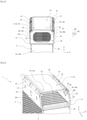
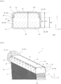
- FIGS. 2 to 7 show different points of views of the header tank 4. More precisely, figures 2, 3 and 7 are side views of the header tank 4, figure 4 is a longitudinal section view of the header tank 4 along a X-X plan illustrated in figure 1 and figures 5 and 6 are transversal sectional views of the header tank 4 along respectively a A-A plan and a B-B plan illustrated in figure 4 . Moreover, it is understood that only one of the first header tank 4a or of the second header tank 4b will be described in detail, but that all of the characteristics described for one header tank apply to the other header tank. Indeed, in the following description we will use the term of header tank 4 to designate irrespectively the first header tank 4a and the second header tank 4b.
- the header tank 4 comprises at least a collecting plate 14, visible in figure 2 , which is U-shaped seen in a sectional view, a cover plate 16 and a cap plate 18.
- the collecting plate 14 comprise at least a back wall 20 and two transversal plates 22, the back wall 20 extending in a main plan, the longitudinal direction L of the header tank 4 being his mainly extension direction, in recovery of the tubes 6.
- at least one tube insertion hole 24 is formed into the back wall 20 of the collecting plate 14 so that the tube insertion hole 24 is fitted onto one end of one tube 6 of the core portion 2.
- a plurality of tube insertion holes 24 are arranged through the back wall 20, each hole from the plurality of the tube insertion holes 24 is configured to cooperate with one end of one tube 6 of the plurality of tubes 6. It is understood that the back wall 20 of the collecting plate 14 comprising the plurality of tube insertion holes 24, allow the hydraulic communication between the header tank 4 and the plurality of tubes 6 of the core portion 2.
- a first transversal plate 22a and a second transversal plate 22b extend perpendicularly from an end of the back plate 20 and in a main plan, the longitudinal direction L of the header tank being his mainly extension direction, and so that the collecting plate 14 is having the U-shape section.
- the collecting plate 44 comprised an inside face 26 which is facing the volume define by the U-shape of the said collecting plate 14.
- At least one lug 28, visible in figure 3 is formed on the inside face 26 of the first transversal plate 22a and/or on the second transversal plate 22b of the collecting plate 14.
- a plurality of lugs 28 are formed on the inside face 26 of the first transversal plate 22a and a plurality of lugs 28 are formed on the inside face 26 of the second transversal plate 22b.
- the plurality of lugs 28 are arranged along the longitudinal direction L of the header tank 4, and are formed so that they are able to support the cover plate 16 of the header tank 4.
- the cover plate 16 of the header tank 4 extends in a plan, the longitudinal direction L of the header tank 4 being his mainly extension direction, and comprises a first curvy end 30a and a second curvy end 30b, visible in figure 6 . More precisely, each of the first curvy end 30a and the second curvy end 30b is formed so that they are in contact respectively with the first transversal plate 22a and the second transversal plate 22b of the collecting plate 14. As it is illustrated, and according of the example of the invention, the first curvy end 30a and the second curvy end 30b are respectively at least in part in contact with the inside face 26 of the first transversal plate 22a and the second transversal plate 22b. It is understood that the curvy ends 30a, 30b of the cover plate 16 are in contact against the plurality of lugs 28 which are formed on the transversal plate 22 of the collecting plate 14, as it was said before.
- the lugs 28 maintain the cover plate 16 in an overlapping position with the collecting plate 14, so that the cover plate 16 participates to define a header tank's 4 internal volume 32. It is understood that the internal volume 32 of the header tank 4 is the volume where the fluid is collected from the engine of the vehicle or from the plurality of tubes 6.
- the header tank 4 comprises the at least one cap plate 18, visible in figures 2 and 7 .
- the header tank 4 comprises a first cap plate 18a and a second cap plate 18b, each respectively located at one longitudinal end of the header tank 4. More precisely, the first cap plate 18a is located to a first longitudinal end 34a of the header tank 4 and the second cap plate 18b is located to a second longitudinal end 34b of the header tank 4. Thereby, the first cap plate 18a and the second cap plate 18b participate to define the internal volume 32 of the header tank 4.
- the cap plate 18, visible in figure 5 has a substantially parallelepiped shape and we define a height H1 of the cap plate 18 measured along a line parallel to the vertical direction V of the header tank 4. More precisely, the height H1 of the cap plate 18 is measured between two ends of the cap plate 18, relative to the vertical direction V of the header tank 4. Moreover, the cap plate 18 comprised a width W1 measured along a line perpendicular to the vertical direction V and to the longitudinal direction L of the header tank 4, and called thereafter the transversal direction T of the header tank 4. The width W1 of the cap plate 18 is measured between the most external ends of the cap plate 18, relative to the transversal direction T of the header tank 4.
- the collecting plate 14 comprised a height H2 measured along a line parallel to the vertical direction V of the header tank 4, and a width W2 of the collection plate 14, measured along a line parallel to the transversal direction T of the header tank 4.
- the width W2 of the collecting plate 14 is measured between the insides faces 26 of the first transversal plate 22a and the second transversal plate 22b of the collecting plate 14.
- the height H1 of the cap plate 18 is lower than the height H2 of the collecting plate 14, and the width W1 of the cap plate 18 is lower than the width W2 of the collecting plate 14. It is understood that the cap plate 18 is designed to be at least partially mounted inside the internal volume 32 of the header tank 4.
- the cap plate 18 comprises also an internal face 36, visible in figure 4 , which facing the internal volume 32 of the header tank 4, and an external face 38 facing an external environment of the header tank 4. As it is illustrated in figure 4 , the cap plate 18 comprises at least one shoulder 40 which is form in the internal face 36 of the cap plate 18 and so that the shoulder 40 is nested at least onto the collecting plate 14 or the cover plate 16.
- the shoulder 40 is designed so that it is nested on to the cover plate 16.
- the shoulder 40 of the cap plate 18 comprises a bearing surface 43 which is facing the cover plate 16, the bearing surface 43 comprising a height H3 measured along a line parallel to the vertical direction V of the header tank 4, between a end of the cap plate relative to the vertical direction V of the header tank 4 and the bearing surface 43.
- the height H3 of the bearing surface 43 is lower than the height H1 of the cap plate 18 and is designed so that the bearing surface 43 of the cap plate 18 rests at least partially against the cover plate 16.
- a material cut 42 visible in figure 6 , is provided in the cap plate 18 so that the material cut 42 is arranged around the first curvy end 30a and/or the second curvy end 30b of the cover plate 16.
- a first material cut 42a and a second material cut 42b is arranged so that it form a rounded in the material of the cap plate 18 adapted to receive respectively each of the first curvy end 30a and the second curvy end 30b of the cover plate 16.
- the material cut 42 comprise a height H4 measured along a line parallel to the vertical direction V of the header tank 4, the height H4 of the material cut 42 is lower than the height H1 of the cap plate 18 and lower than the height H3 of the bearing surface 43 of the shoulder 40.
- the material cut 42 facilitates the assembly of the cover plate 18 at least inside the internal volume 32 of the header tank 4 when the cover plate 16 is previously mounted.
- the cap plate 18 may be fully located inside the internal volume 32 of the header tank 4.
- the cap plate 18 doesn't increase the dimensions of the header tank 4 thanks to the fact that it is integrated into the internal volume 32 of the header tank 4.
- the longitudinal extension of the header tank 4 is not increased by the installation of the cap plate 18.
- the layout of the cap plate 18 inside the internal volume 32 of the header tank 4 participates to increase the sealing of it.
- the header tank 4 comprises at least an overlapping portion 44. Moreover, in order to maintained the cap plate 18 at least in part inside the internal volume 32 of the header tank 4 and with its shoulder 40 nested in the cover plate 16, the header tank 4 comprises at least one tongue 46, visible in figure 3 , made in continuation of the overlapping portion 44.
- the overlapping portion 44 of the header tank 4 is, in this example of the invention, located at least at one free end of one of the transversal plates 22 of the collecting plate 14 and at least at one free end of one of the curvy ends 30 of the cover plate 16.
- each of the first transversal plate 22a and of the second transversal plate 22b comprises an overlapping portion 44 at its free end.
- the overlapping portion 44 extends in the longitudinal direction L of the header tank 4, from the free ends of the transversal plates 22 and from the free ends of the curvy ends 30 of the cover plate 16. It is understood that the overlapping portion 44 may be a curved portion configured to be in contact with the cover plate 16.
- the overlapping portion 44 has the function to maintain the cover plate 16 relative to the vertical direction V of the header tank 4 in a first direction, while the lug 28 have the function to maintain the cover plate 16 relative to the vertical direction V of the header tank 4 in a second direction, opposite to the first direction.
- the overlapping portion 44 comprised at least a gear tooth 45 provided from the free ends of the first transversal plate 22a and the second transversal plate 22b.
- the gear tooth 45 comprised a plurality of teeth between each is provided a space 47, so that it facilitates the folding of at least a part of the overlapping portion 44.
- the tongue 46 which is made in continuation of the overlapping portion 44, relative to the longitudinal direction L of the header tank, is in contact against the external face 38 of the cap plate 18. It is understood that the overlapping portion 44 and the tongue 46 are made out of the collecting plate 14, a connecting portion 48, visible in figure 5 , extending between the overlapping portion 44 and the tongue 46. In others words, the overlapping portion 44 extends over the cover plate 16, the connecting portion 48 is overlapping a thickness 50 of the cap plate 18 and the tongue 46 extends against the external face 38 of the cap plate 18. It is understood that the tongue 46 constitutes also a curved portion of the collecting plate 14.
- a slot may be form between the overlapping portion and the tongue.
- the slot is made so that it is in front of the thickness of the cap plate, so that the thickness of the cap plate is free of any overlapping.
- the slot is a portion which is devoid of material between the overlapping portion and the tongue.
- first radius of curvature R1 of the overlapping portion 44 and a second radius of curvature R2 of the tongue 46 the radius of curvatures R1, R2 being measured relative to a vertical plan of the header tank 4.
- the second radius of curvature R2 is lower than the first radius of curvature R1. It is understood that this characteristic of the second radius of curvature R2 allows the tongue 46 to be in contact against the external face 38 of the cap plate 18, even if the cap plate is inserted inside the internal volume of the header tank.
- the first cap plate 18a may comprise a hole 52 that receives the first pipe 12a of the header tank 4.
- the second cap plate 18b of the header tank 4 has the function to fully close the internal volume 32 of the header tank 4, while the first cap plate 18a is configured to allow the circulation of the fluid by the first pipe 12a inside the internal volume 32 of the header tank 4.
- the cover plate 16 comprises an internal surface 54, visible in figure 4 , which faces the internal volume 32 of the header tank 4, an anticorrosion layer 56, illustrated on figure 4 , being layered against the internal surface 54 of the cover plate 16. More precisely, the anticorrosion layer 56 is layered against the internal surface 54 of the cover plate 16 up to the shoulder 40 of the cap plate 18. Moreover, the internal face 36 of the cap plate 18 and the inside face 26 of the collecting plate 14 comprise also an anticorrosion layer 56. The anticorrosion layer 56 is disposed in order to prevent the corrosion of the header tank 4 due to contact with the high temperature fluid coming from the engine of the vehicle.
- each part of the header tank 4 and the end of the fins 8 and the tubes 6 are layered by an external layer of clad, not show here.
- the clad layer has the function to attach each part of the header tank 4 together and with the plurality of tubes 6 and fins 8 during the brazing process.
- the collecting plate 14 of the header tank 4 is pre-assembled to the core portion of the heat exchanger. More precisely, each tube of the plurality of tubes is inserted inside the tube insertion hole form in the back wall of the collecting plate 14. After the first step, the core portion, including the tubes, the fins and the two side plates, is assembled with the collecting plate 14 of the header tank 4.
- the cap plate 18 is inserted inside the internal volume 32 of the header tank 4 at its longitudinal end 34. More precisely, the first cap plate is inserted in the first longitudinal end of the header tank 4 and the second cap plate 18b is inserted in the second longitudinal end 34b of the header tank 4.
- the first cap plate which comprises the hole that receives the pipe can be mounted directly with the pipe, or the said pipe can be mounted after the first cap plate is inserted in the internal volume of the header tank.
- the cover plate 16 is mounted on the header tank 4 in a manner where the cover plate is inserted inside the collecting plate 14.
- the cover plate 16 is mounted on the collecting plate 14, so that each of the first curvy end 30a and the second curvy end 30b is in contact respectively with the inside face 26 of the first transversal plate 22a and the inside face 26 of the second transversal plate 22b of the collecting plate 14.
- the cover plate 16 is mounted so that each of the first curvy end 30a and the second curvy end 30b is in contact against the plurality of lugs beard by the first transversal plate 22a and/or the second transversal plate 22b.
- a fourth step allows to pre-assembled all this parts together. More precisely, during the fourth step, the overlapping portion 44 is bended. In, the specific example shown here, the overlapping portion 44 is made in a way that the collecting plate 14 is bended over the cover plate 16.
- the overlapping portion can be made in a way that the cover plate is bended over the collecting plate. More precisely, each of the curvy ends of the cover plate is bended over each of the ends of the transversal plates of the collecting plate.
- the tongue 46 is folded in a manner to be in contact against the external face 38 of the cap plate 18. It is understood that the bended and the folded respectively of the overlapping portion 44 and the tongue 46 can be made simultaneously, but the process as covered by the invention covers also the possibility where the overlapping portion 44 or the tongue 46 are bended one after the other.
- the heat exchanger is brazed.
- the clad layer melts in order to attach all parts of the header tank 4 together and with the core portion, in only one brazing operation.
- the invention is offering an advantageous effect in that the general dimensions of the header tank is not increased by the cap plate and is arrangement inside the internal volume of the header tank increase the sealing of the said header tank. More precisely, the invention avoids any mixture between the anticorrosion layer inside the header tank and the clad layer that can be located on external faces of the header tank.
Landscapes
- Engineering & Computer Science (AREA)
- Physics & Mathematics (AREA)
- Thermal Sciences (AREA)
- Mechanical Engineering (AREA)
- General Engineering & Computer Science (AREA)
- Geometry (AREA)
- Heat-Exchange Devices With Radiators And Conduit Assemblies (AREA)
Abstract
Description
- The present invention relates to a heat exchanger used for a cabin of a vehicle or the like which improves the reliability of a header tank of such heat exchanger.
- In general, a heat exchanger is composed of a plurality of tubes connected between a pair of header tanks and installed on a flow path of an air conditioning or heating system. The heat exchanger is configured to exchange heat throughout the heat exchanger in the process of exchanging cold air flowing into the room with hot water heated by an engine. The hot water coming from the engine is then canalized by the header tank of the heat exchanger before being distributed into each tube of the plurality of tubes. In order to ensure the sealing of the heat exchanger, it is known to pre-assemble the heat exchanger with all the parts comprising a layer of clad, before proceed to its brazing in a furnace.
- The use of the hot water coming from the engine presents the drawback of being corrosive for the header tank. Indeed, hot water from the engine is usually glycol water which have some corrosive properties, the header tank usually being manufactured in a metal structure. It is known to use an anticorrosive layer in the volume define by the header tank for protect his metallic structure from the contact with the glycol water. Moreover, the anticorrosive layer is disposed inside the header tank before its brazing.
- This kind of heat exchanger using the anticorrosive layer requires a perfect sealing of the header tank to avoid any mixture of the anticorrosive layer located inside the header tank with the clad layer located on other faces of the header tank, during the brazing process. The means known to date are usually ineffective and increase the dimensions of the heat exchanger which is in inadequation with the general goal of volume reduction of a heat exchanger.
- In view of the above problems, the present invention improves the sealability of the header tank to the heat exchanger while reducing the dimensions of the header tank. In order to achieve the above object, the present invention is about a heat exchanger for thermally treating a vehicle cabin, the heat exchanger comprises a core portion made of at least a plurality of tubes and a plurality of fins, the heat exchanger comprises at least one header tank located at one end of the core portion, the header tank comprises at least a collecting plate which have a U-shape, a cover plate connected to the collecting plate and at least one cap plate which is located at one longitudinal end of the header tank, the collecting plate and the cover plate are linked together by an overlapping portion, the collecting plate, the cover plate and the cap plate are defining an internal volume of the header tank that is hydraulically communicating with the core portion, the heat exchanger is characterized in that the cap plate is at least partially mounted inside the internal volume and maintained in position by a tongue made in continuation of the overlapping portion.
- In the core portion of the heat exchanger, each tube from the plurality of tubes is disposed alternatively with each fin of the plurality of fins. Indeed, the heat exchanger is configured so that a high temperature fluid heat flows through the tubes from the header tank and so that the high temperature fluid is able to exchanges heat with a cold air passing through the fins to the vehicle cabin. The header tank is configured to receive the high temperature fluid from an engine of a vehicle before being dispenses into each tube.
- The header tank has a main elongation direction which is called the longitudinal direction of the header tank. The at least one cap plate is located to one longitudinal end of the header tank, relative to its longitudinal direction.
- We take advantage of the configuration of the tongue which is made in the continuation of the overlapping portion in a manner that the fixation of the cover plate and the cap plate within the header tank may be realized during the same operation and in an easy way which doesn't increase the general dimensions of the header tank.
- According to the invention, the cap plate comprises an external face facing an external environment of the header tank, the tongue being in contact with the external face of the cap plate.
- It is understood that the tongue locks the position of the cap plate at least in part inside the internal volume of the header tank. More precisely, the tongue locks the cap plate in position relative to the longitudinal direction of the header tank.
- According to the invention, the overlapping portion and the tongue are made out of the collecting plate.
- According to an alternative to the invention, the overlapping portion and the tongue are made out of the cover plate.
- According to the invention, the heat exchanger comprises a connecting portion that links the overlapping portion to the tongue. In other words, the connecting portion is overlapped a thickness of the cap plate. The connecting portion is in continuity of the overlapping portion and of the tongue.
- According to an alternative of the invention, the heat exchanger comprises a slot between the overlapping portion and the tongue. The slot is made so that it is in front of the thickness of the cap plate. We take advantage of this configuration of the heat exchanger in that it eases the folding of the tongue.
- According to the invention, at least the overlapping portion and/or the tongue is a curved portion.
- According to an advantageous embodiment of the invention, both of the overlapping portion and the tongue are a curved portion, visible in a plan perpendicular to a main elongation plan of the header tank, the main elongation plan of the header comprising the longitudinal direction of it.
- According to the invention, the overlapping portion is defined by a first radius of curvature and the tongue is defined by a second radius of curvature, the second radius of curvature is being lower than the first radius of curvature.
- According to the invention, the cap plate comprises at least one shoulder that is nested at least in the collecting plate and/or in the cover plate.
- The shoulder comprises at least a bearing surface against which the collecting plate or the cover plate rests.
- According to the invention, the shoulder is nested in the cover plate and that the cap plate is fully located inside the internal volume of the header tank.
- It is understood that the cover plate is in contact against the bearing surface of the shoulder.
- According to an alternative of the invention, the shoulder is nested in the collecting plate and the cap plate is fully located inside the cover plate.
- It is understood that at least one part or the collecting plate is in contact against the bearing surface of the shoulder.
- According to an example of the invention, a height of the bearing surface of the shoulder measured along a main elongation direction of the tubes is lower than a height of the cap plate measured along the main elongation direction of the tubes between two vertical ends of the cap plate relative to the main elongation direction of the tubes.
- According to these two alternatives of the invention, a width of the cap plate measured along a line perpendicular to the longitudinal direction of the header tank and the main elongation direction of the tubes is lower than a width of the collecting plate measured along a line perpendicular to the longitudinal direction of the header tank and the main elongation direction of the tubes.
- According to an example of the invention, the height of the cap plate measured along the main elongation direction of the tubes is lower than a height of the collecting plate measured along the main elongation direction of the tubes.
- According to the invention, the cover plate comprises an internal surface facing the internal volume, an anticorrosion layer being layered against the internal surface of the cover plate. The anticorrosion layer is layered against the internal surface of the cover plate up to the shoulder of the cap plate.
- Moreover, an internal face of the cap plate facing the internal volume of the header tank, that is to say opposite to the external face relative to the longitudinal direction of the header tank, and an inside face of the collecting plate which is facing the internal volume, comprise an anticorrosion layer.
- According to the invention, the collecting plate comprises at least one lug that extends inside the internal volume defined by the header tank, the cover plate resting at least partially against the lug.
- According to the invention, the cap plate comprises a hole that receives a pipe. The pipe is configured to allow the entry or the exit of the high temperature fluid in or from the internal volume of the header tank of the heat exchanger.
- According to the invention, the collecting plate comprises a back wall in which at least one tube insertion hole is formed, the cover plate being located at the opposite of the back wall relative to a perpendicular line of a main back wall plan of the header tank.
- The invention is also about a mounting process of a heat exchanger according to one of the preceding characterize, in which, during a first step, the collecting plate is pre-assembled to the core portion, during a second step, the cap plate is inserted in a longitudinal end of the header tank, during a third step, the cover plate is covering the collecting plate and during a fourth step, the overlapping portion is bended over the cover plate and/or the tongue is folded in order to contact an external face of the cap plate.
- According to the mounting process of the heat exchanger, in which during a subsequent step after the fourth step, the heat exchanger is brazed.
- Before the pre-assembling steps of the heat exchanger, a clad layer is layered on each part which composes the heat exchanger. More precisely, the clad layer and the anticorrosion layer are laminated before machining parts which composes the heat exchanger. The clad layer allows to attach all parts of the heat exchanger all together, in one single step.
- It is understood that the integrality of the heat exchanger is brazed, the clad layer of on part of the header tank, the cap plat for example, being melted with the clad layer of another part of the header tank, for example the collecting plate and/or the cover plate. Moreover, the anticorrosion layer is layered on the face of the parts that are facing the internal volume of the header tank, as it was said previously.
- [
Fig 1 ] is a perspective view of a heat exchanger according to the invention; - [
Fig 2 ] is a side view of a header tank of the heat exchanger offigure 1 , showing an example of cap plate; - [
Fig 3 ] is another side view of the header tank of the heat exchanger, showing a collecting plate and a cover plate; - [
Fig 4 ] is a longitudinal sectional view of a part of the header tank, showing the cap plate, the cover plate and the collecting plate; - [
Fig 5 ] is a first transversal sectional view of the cap plate; - [
Fig 6 ] is a second transversal sectional view of the cap plate; - [
Fig 7 ] is a perspective view of the header tank showing a cap plate according to another example of the invention; - [
Fig 8 ] is a perspective view of the header tank, showing steps of a mounting process of the heat exchanger. -
Figure 1 is a perspective view showing aheat exchanger 1 according to an embodiment of the present invention. Theheat exchanger 1 comprised acore portion 2 and at least oneheader tank 4. Thecore portion 2 of theheat exchanger 1 comprises at least a plurality oftubes 6, a plurality offins 8 and a side plate 10. More precisely, thecore portion 2 is formed by alternately eachtube 6 of the plurality oftubes 6 with eachfin 8 of the plurality offins 8, in multiple layers. A first side plate 10a and a second side plate 10b are provided on both end surface of thecore portion 2 in the direction which thetubes 6 and the fins 10 are alternately arranged. It is understood that the first side plate 10a and the second side plate 10b close the volume of thecore portion 2 along a direction perpendicular to a main elongation direction U of thetubes 6 of thecore portion 2. - The
heat exchanger 1 is configured so that a high temperature fluid flows through thetubes 6 and so that the high temperature fluid is able to exchanges heat with a cold air passing through thefins 8, and sent to a vehicle cabin. In order to dispense the high temperature fluid into thetubes 6, theheader tank 4 is configured to receive the said high temperature fluid from an engine of a vehicle before being dispenses into thetubes 6. According to the illustrated example of the invention, theheat exchanger 1 comprises a first header tank 4a and a second header tank 4b each located at one end of the plurality of thetubes 6, relatives to them main elongation direction U and called thereafter the vertical direction V of theheader tank 4. Each of the first header tank 4a and the second header tank 4b is arranged so that it covers the whole ends of thetubes 6 which it facing. - It is understood that the first header tank 4a receives the high temperature fluid from the engine by means of a first pipe 12a, and that the second header tank 4b collects the fluid relieved of his heat from the
tubes 6 so that it discharges the said fluid outside theheat exchanger 1 by means a second pipe 12b. We define a main elongation direction of these two header tanks 4a, 4b, which is called thereafter longitudinal direction L of theheader tank 4, said longitudinal direction L being parallel to the direction in which thetubes 6 and thefins 8 are alternatively arranged. So, each of the first pipe 12a and of the second pipe 12b is arranged at a longitudinal end of theheader tank 4 in which he is united. - The
header tank 4 will now be described with thefigures 2 to 7 showing different points of views of theheader tank 4. More precisely,figures 2, 3 and7 are side views of theheader tank 4,figure 4 is a longitudinal section view of theheader tank 4 along a X-X plan illustrated infigure 1 andfigures 5 and6 are transversal sectional views of theheader tank 4 along respectively a A-A plan and a B-B plan illustrated infigure 4 . Moreover, it is understood that only one of the first header tank 4a or of the second header tank 4b will be described in detail, but that all of the characteristics described for one header tank apply to the other header tank. Indeed, in the following description we will use the term ofheader tank 4 to designate irrespectively the first header tank 4a and the second header tank 4b. - The
header tank 4 comprises at least a collectingplate 14, visible infigure 2 , which is U-shaped seen in a sectional view, acover plate 16 and acap plate 18. The collectingplate 14 comprise at least aback wall 20 and twotransversal plates 22, theback wall 20 extending in a main plan, the longitudinal direction L of theheader tank 4 being his mainly extension direction, in recovery of thetubes 6. Furthermore, at least onetube insertion hole 24 is formed into theback wall 20 of the collectingplate 14 so that thetube insertion hole 24 is fitted onto one end of onetube 6 of thecore portion 2. According to the illustrating example of the invention, a plurality of tube insertion holes 24 are arranged through theback wall 20, each hole from the plurality of the tube insertion holes 24 is configured to cooperate with one end of onetube 6 of the plurality oftubes 6. It is understood that theback wall 20 of the collectingplate 14 comprising the plurality of tube insertion holes 24, allow the hydraulic communication between theheader tank 4 and the plurality oftubes 6 of thecore portion 2. - A first
transversal plate 22a and a secondtransversal plate 22b extend perpendicularly from an end of theback plate 20 and in a main plan, the longitudinal direction L of the header tank being his mainly extension direction, and so that the collectingplate 14 is having the U-shape section. The collectingplate 44 comprised aninside face 26 which is facing the volume define by the U-shape of the saidcollecting plate 14. At least onelug 28, visible infigure 3 , is formed on theinside face 26 of the firsttransversal plate 22a and/or on the secondtransversal plate 22b of the collectingplate 14. According to an illustration of the invention, a plurality oflugs 28 are formed on theinside face 26 of the firsttransversal plate 22a and a plurality oflugs 28 are formed on theinside face 26 of the secondtransversal plate 22b. The plurality oflugs 28 are arranged along the longitudinal direction L of theheader tank 4, and are formed so that they are able to support thecover plate 16 of theheader tank 4. - The
cover plate 16 of theheader tank 4 extends in a plan, the longitudinal direction L of theheader tank 4 being his mainly extension direction, and comprises a first curvy end 30a and a second curvy end 30b, visible infigure 6 . More precisely, each of the first curvy end 30a and the second curvy end 30b is formed so that they are in contact respectively with the firsttransversal plate 22a and the secondtransversal plate 22b of the collectingplate 14. As it is illustrated, and according of the example of the invention, the first curvy end 30a and the second curvy end 30b are respectively at least in part in contact with theinside face 26 of the firsttransversal plate 22a and the secondtransversal plate 22b. It is understood that the curvy ends 30a, 30b of thecover plate 16 are in contact against the plurality oflugs 28 which are formed on thetransversal plate 22 of the collectingplate 14, as it was said before. - The
lugs 28 maintain thecover plate 16 in an overlapping position with the collectingplate 14, so that thecover plate 16 participates to define a header tank's 4internal volume 32. It is understood that theinternal volume 32 of theheader tank 4 is the volume where the fluid is collected from the engine of the vehicle or from the plurality oftubes 6. - In order to close longitudinally the
internal volume 32, theheader tank 4 comprises the at least onecap plate 18, visible infigures 2 and7 . According to the illustrating examples of the invention, theheader tank 4 comprises afirst cap plate 18a and asecond cap plate 18b, each respectively located at one longitudinal end of theheader tank 4. More precisely, thefirst cap plate 18a is located to a first longitudinal end 34a of theheader tank 4 and thesecond cap plate 18b is located to a second longitudinal end 34b of theheader tank 4. Thereby, thefirst cap plate 18a and thesecond cap plate 18b participate to define theinternal volume 32 of theheader tank 4. - In the following description, the
second cap plate 18b will be described, thefirst cap plate 18a will be describe later in the following description. - The
cap plate 18, visible infigure 5 , has a substantially parallelepiped shape and we define a height H1 of thecap plate 18 measured along a line parallel to the vertical direction V of theheader tank 4. More precisely, the height H1 of thecap plate 18 is measured between two ends of thecap plate 18, relative to the vertical direction V of theheader tank 4. Moreover, thecap plate 18 comprised a width W1 measured along a line perpendicular to the vertical direction V and to the longitudinal direction L of theheader tank 4, and called thereafter the transversal direction T of theheader tank 4. The width W1 of thecap plate 18 is measured between the most external ends of thecap plate 18, relative to the transversal direction T of theheader tank 4. - In the same way, the collecting
plate 14 comprised a height H2 measured along a line parallel to the vertical direction V of theheader tank 4, and a width W2 of thecollection plate 14, measured along a line parallel to the transversal direction T of theheader tank 4. The width W2 of the collectingplate 14 is measured between the insides faces 26 of the firsttransversal plate 22a and the secondtransversal plate 22b of the collectingplate 14. - According to an aspect of the invention, the height H1 of the
cap plate 18 is lower than the height H2 of the collectingplate 14, and the width W1 of thecap plate 18 is lower than the width W2 of the collectingplate 14. It is understood that thecap plate 18 is designed to be at least partially mounted inside theinternal volume 32 of theheader tank 4. - The
cap plate 18 comprises also aninternal face 36, visible infigure 4 , which facing theinternal volume 32 of theheader tank 4, and anexternal face 38 facing an external environment of theheader tank 4. As it is illustrated infigure 4 , thecap plate 18 comprises at least oneshoulder 40 which is form in theinternal face 36 of thecap plate 18 and so that theshoulder 40 is nested at least onto the collectingplate 14 or thecover plate 16. - According to the illustrating example of the invention, the
shoulder 40 is designed so that it is nested on to thecover plate 16. In other words, theshoulder 40 of thecap plate 18 comprises a bearingsurface 43 which is facing thecover plate 16, the bearingsurface 43 comprising a height H3 measured along a line parallel to the vertical direction V of theheader tank 4, between a end of the cap plate relative to the vertical direction V of theheader tank 4 and the bearingsurface 43. The height H3 of the bearingsurface 43 is lower than the height H1 of thecap plate 18 and is designed so that the bearingsurface 43 of thecap plate 18 rests at least partially against thecover plate 16. - A material cut 42, visible in
figure 6 , is provided in thecap plate 18 so that the material cut 42 is arranged around the first curvy end 30a and/or the second curvy end 30b of thecover plate 16. Afirst material cut 42a and asecond material cut 42b is arranged so that it form a rounded in the material of thecap plate 18 adapted to receive respectively each of the first curvy end 30a and the second curvy end 30b of thecover plate 16. Thereby, the material cut 42 comprise a height H4 measured along a line parallel to the vertical direction V of theheader tank 4, the height H4 of the material cut 42 is lower than the height H1 of thecap plate 18 and lower than the height H3 of the bearingsurface 43 of theshoulder 40. The material cut 42 facilitates the assembly of thecover plate 18 at least inside theinternal volume 32 of theheader tank 4 when thecover plate 16 is previously mounted. - We take advantage of these characteristics of the
cap plate 18, in that the saidcap plate 18 may be fully located inside theinternal volume 32 of theheader tank 4. Thereby, thecap plate 18 doesn't increase the dimensions of theheader tank 4 thanks to the fact that it is integrated into theinternal volume 32 of theheader tank 4. In other words, the longitudinal extension of theheader tank 4 is not increased by the installation of thecap plate 18. Moreover, the layout of thecap plate 18 inside theinternal volume 32 of theheader tank 4 participates to increase the sealing of it. - In order to link together the
cover plate 16 and the collectingplate 14, theheader tank 4 comprises at least an overlappingportion 44. Moreover, in order to maintained thecap plate 18 at least in part inside theinternal volume 32 of theheader tank 4 and with itsshoulder 40 nested in thecover plate 16, theheader tank 4 comprises at least onetongue 46, visible infigure 3 , made in continuation of the overlappingportion 44. - The overlapping
portion 44 of theheader tank 4 is, in this example of the invention, located at least at one free end of one of thetransversal plates 22 of the collectingplate 14 and at least at one free end of one of the curvy ends 30 of thecover plate 16. According to the illustrating example of the invention, each of the firsttransversal plate 22a and of the secondtransversal plate 22b comprises an overlappingportion 44 at its free end. More precisely, the overlappingportion 44 extends in the longitudinal direction L of theheader tank 4, from the free ends of thetransversal plates 22 and from the free ends of the curvy ends 30 of thecover plate 16. It is understood that the overlappingportion 44 may be a curved portion configured to be in contact with thecover plate 16. - The overlapping
portion 44 has the function to maintain thecover plate 16 relative to the vertical direction V of theheader tank 4 in a first direction, while thelug 28 have the function to maintain thecover plate 16 relative to the vertical direction V of theheader tank 4 in a second direction, opposite to the first direction. - As it is show in
figure 3 , the overlappingportion 44 comprised at least agear tooth 45 provided from the free ends of the firsttransversal plate 22a and the secondtransversal plate 22b. Thegear tooth 45 comprised a plurality of teeth between each is provided aspace 47, so that it facilitates the folding of at least a part of the overlappingportion 44. - The
tongue 46 which is made in continuation of the overlappingportion 44, relative to the longitudinal direction L of the header tank, is in contact against theexternal face 38 of thecap plate 18. It is understood that the overlappingportion 44 and thetongue 46 are made out of the collectingplate 14, a connectingportion 48, visible infigure 5 , extending between the overlappingportion 44 and thetongue 46. In others words, the overlappingportion 44 extends over thecover plate 16, the connectingportion 48 is overlapping athickness 50 of thecap plate 18 and thetongue 46 extends against theexternal face 38 of thecap plate 18. It is understood that thetongue 46 constitutes also a curved portion of the collectingplate 14. - In another embodiment of the invention, not illustrated here, a slot may be form between the overlapping portion and the tongue. The slot is made so that it is in front of the thickness of the cap plate, so that the thickness of the cap plate is free of any overlapping. In other words, the slot is a portion which is devoid of material between the overlapping portion and the tongue.
- We define a first radius of curvature R1 of the overlapping
portion 44 and a second radius of curvature R2 of thetongue 46, the radius of curvatures R1, R2 being measured relative to a vertical plan of theheader tank 4. According to the invention, the second radius of curvature R2 is lower than the first radius of curvature R1. It is understood that this characteristic of the second radius of curvature R2 allows thetongue 46 to be in contact against theexternal face 38 of thecap plate 18, even if the cap plate is inserted inside the internal volume of the header tank. - As it is illustrated in
figure 2 , thefirst cap plate 18a may comprise ahole 52 that receives the first pipe 12a of theheader tank 4. As it can be seen infigure 7 , thesecond cap plate 18b of theheader tank 4 has the function to fully close theinternal volume 32 of theheader tank 4, while thefirst cap plate 18a is configured to allow the circulation of the fluid by the first pipe 12a inside theinternal volume 32 of theheader tank 4. - According to the invention, the
cover plate 16 comprises aninternal surface 54, visible infigure 4 , which faces theinternal volume 32 of theheader tank 4, ananticorrosion layer 56, illustrated onfigure 4 , being layered against theinternal surface 54 of thecover plate 16. More precisely, theanticorrosion layer 56 is layered against theinternal surface 54 of thecover plate 16 up to theshoulder 40 of thecap plate 18. Moreover, theinternal face 36 of thecap plate 18 and theinside face 26 of the collectingplate 14 comprise also ananticorrosion layer 56. Theanticorrosion layer 56 is disposed in order to prevent the corrosion of theheader tank 4 due to contact with the high temperature fluid coming from the engine of the vehicle. In addition to theanticorrosion layer 56, each part of theheader tank 4 and the end of thefins 8 and thetubes 6 are layered by an external layer of clad, not show here. The clad layer has the function to attach each part of theheader tank 4 together and with the plurality oftubes 6 andfins 8 during the brazing process. - A mounting process of the heat exchanger will now be described, relative to
figure 8 . It is understood that all the components of the heat exchanger used for the mounting process are previously layered with the clad layer and the anticorrosion layer as it was described previously. - During the first step of the mounting process, the collecting
plate 14 of theheader tank 4 is pre-assembled to the core portion of the heat exchanger. More precisely, each tube of the plurality of tubes is inserted inside the tube insertion hole form in the back wall of the collectingplate 14. After the first step, the core portion, including the tubes, the fins and the two side plates, is assembled with the collectingplate 14 of theheader tank 4. - During the second step of the mounting process, the
cap plate 18 is inserted inside theinternal volume 32 of theheader tank 4 at itslongitudinal end 34. More precisely, the first cap plate is inserted in the first longitudinal end of theheader tank 4 and thesecond cap plate 18b is inserted in the second longitudinal end 34b of theheader tank 4. The first cap plate which comprises the hole that receives the pipe can be mounted directly with the pipe, or the said pipe can be mounted after the first cap plate is inserted in the internal volume of the header tank. - During a third step of the mounting process, the
cover plate 16 is mounted on theheader tank 4 in a manner where the cover plate is inserted inside the collectingplate 14. Of course, the opposite way is also covered by the invention. More precisely, thecover plate 16 is mounted on the collectingplate 14, so that each of the first curvy end 30a and the second curvy end 30b is in contact respectively with theinside face 26 of the firsttransversal plate 22a and theinside face 26 of the secondtransversal plate 22b of the collectingplate 14. Thecover plate 16 is mounted so that each of the first curvy end 30a and the second curvy end 30b is in contact against the plurality of lugs beard by the firsttransversal plate 22a and/or the secondtransversal plate 22b. - Once the collecting
plate 14, thecover plate 16 and the twocap plates 18 are assembled together, a fourth step allows to pre-assembled all this parts together. More precisely, during the fourth step, the overlappingportion 44 is bended. In, the specific example shown here, the overlappingportion 44 is made in a way that the collectingplate 14 is bended over thecover plate 16. - According to an alternative of the invention, not illustrated, the overlapping portion can be made in a way that the cover plate is bended over the collecting plate. More precisely, each of the curvy ends of the cover plate is bended over each of the ends of the transversal plates of the collecting plate.
- The
tongue 46 is folded in a manner to be in contact against theexternal face 38 of thecap plate 18. It is understood that the bended and the folded respectively of the overlappingportion 44 and thetongue 46 can be made simultaneously, but the process as covered by the invention covers also the possibility where the overlappingportion 44 or thetongue 46 are bended one after the other. - Finally, during a subsequent step after the fourth step, the heat exchanger is brazed. During the brazing operation, the clad layer melts in order to attach all parts of the
header tank 4 together and with the core portion, in only one brazing operation. - The invention is offering an advantageous effect in that the general dimensions of the header tank is not increased by the cap plate and is arrangement inside the internal volume of the header tank increase the sealing of the said header tank. More precisely, the invention avoids any mixture between the anticorrosion layer inside the header tank and the clad layer that can be located on external faces of the header tank.
Claims (16)
- Heat exchanger (1) for thermally treating a vehicle cabin, the heat exchanger (1) comprises a core portion (2) made of at least a plurality of tubes (6) and a plurality of fins (8), the heat exchanger (1) comprises at least one header tank (4) located at one end of the core portion (2), the header tank (4) comprises at least a collecting plate (14) which have a U-shape, a cover plate (16) connected to the collecting plate (14) and at least one cap plate (18) which is located at one longitudinal end (34) of the header tank (4), the collecting plate (14) and the cover plate (16) are linked together by an overlapping portion (44), the collecting plate (14), the cover plate (16) and the cap plate (18) are defining an internal volume (32) of the header tank (4) that is hydraulically communicating with the core portion (2), the heat exchanger (1) is characterized in that the cap plate (18) is at least partially mounted inside the internal volume (32) and maintained in position by a tongue (46) made in continuation of the overlapping portion (44).
- Heat exchanger (1) according to claim 1, wherein the cap plate (18) comprises an external face (38) facing an external environment of the header tank (4), the tongue (46) being in contact with the external face (38) of the cap plate (18).
- Heat exchanger (1) according to claim 1 or 2, wherein the overlapping portion (44) and the tongue (46) are made out of the collecting plate (14).
- Heat exchanger (1) according to claim 1 or 2, wherein the overlapping portion (44) and the tongue (46) are made out of the cover plate (16).
- Heat exchanger according to one of the claims 1 to 4, comprising a connecting portion (48) that links the overlapping portion (44) to the tongue (46).
- Heat exchanger according to one of the claims 1 to 6, wherein at least the overlapping portion (44) and/or the tongue (46) is a curved portion.
- Heat exchanger according to claim 7, wherein the overlapping portion (44) is defined by a first radius of curvature (R1) and the tongue (46) is defined by a second radius of curvature (R2), the second radius of curvature (R2) is being lower than the first radius of curvature (R1).
- Heat exchanger (1) according to one of the claims 1 to 8, wherein the cap plate (18) comprises at least one shoulder (40) that is nested at least in the collecting plate (14) and/or in the cover plate (16).
- Heat exchanger (1) according to claim 9, wherein the shoulder (40) is nested in the cover plate (16) and that the cap plate (18) is fully located inside the internal volume (32) of the header tank (4)
- Heat exchanger (1) according to claim 9, wherein the shoulder (40) is nested in the collecting plate (14) and the cap plate (18) is fully located inside the cover plate (16).
- Heat exchanger (1) according to one of the claims 1 to 11, wherein the cover plate (16) comprises an internal surface (54) facing the internal volume (32), an anticorrosion layer (56) being layered against the internal surface (54) of the cover plate (16).
- Heat exchanger (1) according to one of the claims 1 to 12, wherein the collecting plate (14) comprises at least one lug (28) that extends inside the internal volume (32) defined by the header tank (4), the cover plate (16) resting at least partially against the lug (28).
- Heat exchanger according to one of the claims 1 to 13, wherein the cap plate (18) comprises a hole (52) that receives a pipe (12).
- Heat exchanger according to one of the claims 1 to 14, wherein the collecting plate (14) comprises a back wall (20) in which at least one tube insertion hole (24) is formed, the cover plate (16) being located at the opposite of the back wall (20) relative to a perpendicular line of a main back wall plan of the header tank (4).
- Mounting process of a heat exchanger (1) according to one of the preceding claims, in which, during a first step, the collecting plate (14) is pre-assembled to the core portion (2), during a second step, the cap plate (18) is inserted in a longitudinal end (34) of the header tank (4), during a third step, the cover plate (16) is covering the collecting plate (14) and during a fourth step, the overlapping portion (44) is bended over the cover plate (16) and/or the tongue (46) is folded in order to contact an external face (38) of the cap plate (18).
- Mounting process of the heat exchanger (1) according to claim 16, in which during a subsequent step after the fourth step, the heat exchanger (1) is brazed.
Priority Applications (4)
| Application Number | Priority Date | Filing Date | Title |
|---|---|---|---|
| EP20187386.6A EP3943866B1 (en) | 2020-07-23 | 2020-07-23 | Heat exchanger |
| US18/006,473 US20230272984A1 (en) | 2020-07-23 | 2021-06-29 | Heat exchanger |
| PCT/EP2021/067902 WO2022017739A1 (en) | 2020-07-23 | 2021-06-29 | Heat exchanger |
| CN202180050258.0A CN115956188A (en) | 2020-07-23 | 2021-06-29 | Heat exchanger |
Applications Claiming Priority (1)
| Application Number | Priority Date | Filing Date | Title |
|---|---|---|---|
| EP20187386.6A EP3943866B1 (en) | 2020-07-23 | 2020-07-23 | Heat exchanger |
Publications (2)
| Publication Number | Publication Date |
|---|---|
| EP3943866A1 true EP3943866A1 (en) | 2022-01-26 |
| EP3943866B1 EP3943866B1 (en) | 2023-09-13 |
Family
ID=71783893
Family Applications (1)
| Application Number | Title | Priority Date | Filing Date |
|---|---|---|---|
| EP20187386.6A Active EP3943866B1 (en) | 2020-07-23 | 2020-07-23 | Heat exchanger |
Country Status (4)
| Country | Link |
|---|---|
| US (1) | US20230272984A1 (en) |
| EP (1) | EP3943866B1 (en) |
| CN (1) | CN115956188A (en) |
| WO (1) | WO2022017739A1 (en) |
Families Citing this family (1)
| Publication number | Priority date | Publication date | Assignee | Title |
|---|---|---|---|---|
| EP4553440A1 (en) * | 2023-11-08 | 2025-05-14 | Valeo Systemes Thermiques | A tank for a heat exchanger |
Citations (3)
| Publication number | Priority date | Publication date | Assignee | Title |
|---|---|---|---|---|
| EP1541956A2 (en) * | 2003-12-08 | 2005-06-15 | Calsonic Kansei Corporation | Tank structure |
| JP2010085025A (en) * | 2008-09-30 | 2010-04-15 | Calsonic Kansei Corp | Heat exchanger |
| FR3089607A1 (en) * | 2018-12-10 | 2020-06-12 | Valeo Systemes Thermiques | COLLECTOR BOX FOR HEAT EXCHANGER AND HEAT EXCHANGER COMPRISING SUCH A COLLECTOR BOX |
Family Cites Families (10)
| Publication number | Priority date | Publication date | Assignee | Title |
|---|---|---|---|---|
| IT969325B (en) * | 1971-08-06 | 1974-03-30 | Chausson Usines Sa | PROCEDURE FOR THE BRAZING OF ALUMINUM AND RADIATORS RE OBTAINED |
| US5341872A (en) * | 1993-05-19 | 1994-08-30 | Valeo Engine Cooling Inc. | Heat exchanger and manifold therefor, and method of assembly thereof |
| JP3329893B2 (en) * | 1993-07-20 | 2002-09-30 | 株式会社ゼクセルヴァレオクライメートコントロール | Heat exchanger header tank |
| JP2000304488A (en) * | 1999-04-23 | 2000-11-02 | Calsonic Kansei Corp | Aluminum alloy heat exchanger |
| JP2009210141A (en) * | 2008-02-29 | 2009-09-17 | Showa Denko Kk | Header tank for heat exchanger, and manufacturing method of heat exchanger |
| KR101580233B1 (en) * | 2010-07-02 | 2015-12-24 | 한온시스템 주식회사 | The heat exchanger |
| FR2967764B1 (en) * | 2010-11-19 | 2012-12-21 | Valeo Systemes Thermiques | COLLECTOR BOX AND CORRESPONDING HEAT EXCHANGER |
| FR2973492B1 (en) * | 2011-03-31 | 2017-12-15 | Valeo Systemes Thermiques | COLLECTOR BOX FOR A HEAT EXCHANGER, IN PARTICULAR FOR A MOTOR VEHICLE, AND THERMAL EXCHANGER THEREFOR |
| US9459057B2 (en) * | 2013-01-24 | 2016-10-04 | Alcoll USA LLC | Heat exchanger |
| US11460256B2 (en) * | 2016-06-23 | 2022-10-04 | Modine Manufacturing Company | Heat exchanger header |
-
2020
- 2020-07-23 EP EP20187386.6A patent/EP3943866B1/en active Active
-
2021
- 2021-06-29 US US18/006,473 patent/US20230272984A1/en active Pending
- 2021-06-29 CN CN202180050258.0A patent/CN115956188A/en active Pending
- 2021-06-29 WO PCT/EP2021/067902 patent/WO2022017739A1/en not_active Ceased
Patent Citations (3)
| Publication number | Priority date | Publication date | Assignee | Title |
|---|---|---|---|---|
| EP1541956A2 (en) * | 2003-12-08 | 2005-06-15 | Calsonic Kansei Corporation | Tank structure |
| JP2010085025A (en) * | 2008-09-30 | 2010-04-15 | Calsonic Kansei Corp | Heat exchanger |
| FR3089607A1 (en) * | 2018-12-10 | 2020-06-12 | Valeo Systemes Thermiques | COLLECTOR BOX FOR HEAT EXCHANGER AND HEAT EXCHANGER COMPRISING SUCH A COLLECTOR BOX |
Also Published As
| Publication number | Publication date |
|---|---|
| US20230272984A1 (en) | 2023-08-31 |
| WO2022017739A1 (en) | 2022-01-27 |
| EP3943866B1 (en) | 2023-09-13 |
| CN115956188A (en) | 2023-04-11 |
Similar Documents
| Publication | Publication Date | Title |
|---|---|---|
| US5307870A (en) | Heat exchanger | |
| US6305465B1 (en) | Double heat exchanger having condenser core and radiator core | |
| EP1172623B1 (en) | Heat exchanger and fluid pipe therefor | |
| US5240068A (en) | Heat exchanger | |
| JP3912836B2 (en) | Heat exchanger | |
| EP1158260B1 (en) | Heat exchanger, method of manufacturing the heat exchanger, and method of manufacturing tube for heat exchange | |
| US20090014164A1 (en) | Flat tube, flat tube heat exchanger, and method of manufacturing same | |
| JPH11148794A (en) | Heat exchanger | |
| JP4105320B2 (en) | Heat exchanger | |
| US20120043063A1 (en) | Exhaust gas heat exchanger and method of operating the same | |
| JP3329893B2 (en) | Heat exchanger header tank | |
| WO2005047800A1 (en) | Evaporator and process for fabricating same | |
| EP0625687B1 (en) | Heat exchanger and manifold therefor, and method of assembly thereof | |
| EP1843119A1 (en) | Radiator | |
| EP3943866B1 (en) | Heat exchanger | |
| JP2000154993A (en) | Heat exchanger | |
| JP4533726B2 (en) | Evaporator and manufacturing method thereof | |
| JPH0345300B2 (en) | ||
| EP1146311B1 (en) | Sacrifice corrosion layer forming method | |
| US20050006066A1 (en) | Heat exchanger useful as charge-air cooler for commercial vehicles | |
| JPH0245945B2 (en) | ||
| JP4682494B2 (en) | Heat exchanger | |
| US20050006081A1 (en) | Compound type heat exchanger | |
| JPH11223486A (en) | Integrally juxtaposed heat exchanger and manufacture therefor | |
| JP3843340B2 (en) | Heat exchanger |
Legal Events
| Date | Code | Title | Description |
|---|---|---|---|
| PUAI | Public reference made under article 153(3) epc to a published international application that has entered the european phase |
Free format text: ORIGINAL CODE: 0009012 |
|
| STAA | Information on the status of an ep patent application or granted ep patent |
Free format text: STATUS: THE APPLICATION HAS BEEN PUBLISHED |
|
| AK | Designated contracting states |
Kind code of ref document: A1 Designated state(s): AL AT BE BG CH CY CZ DE DK EE ES FI FR GB GR HR HU IE IS IT LI LT LU LV MC MK MT NL NO PL PT RO RS SE SI SK SM TR |
|
| STAA | Information on the status of an ep patent application or granted ep patent |
Free format text: STATUS: REQUEST FOR EXAMINATION WAS MADE |
|
| 17P | Request for examination filed |
Effective date: 20220707 |
|
| RBV | Designated contracting states (corrected) |
Designated state(s): AL AT BE BG CH CY CZ DE DK EE ES FI FR GB GR HR HU IE IS IT LI LT LU LV MC MK MT NL NO PL PT RO RS SE SI SK SM TR |
|
| GRAP | Despatch of communication of intention to grant a patent |
Free format text: ORIGINAL CODE: EPIDOSNIGR1 |
|
| STAA | Information on the status of an ep patent application or granted ep patent |
Free format text: STATUS: GRANT OF PATENT IS INTENDED |
|
| INTG | Intention to grant announced |
Effective date: 20230508 |
|
| P01 | Opt-out of the competence of the unified patent court (upc) registered |
Effective date: 20230528 |
|
| GRAS | Grant fee paid |
Free format text: ORIGINAL CODE: EPIDOSNIGR3 |
|
| GRAA | (expected) grant |
Free format text: ORIGINAL CODE: 0009210 |
|
| STAA | Information on the status of an ep patent application or granted ep patent |
Free format text: STATUS: THE PATENT HAS BEEN GRANTED |
|
| AK | Designated contracting states |
Kind code of ref document: B1 Designated state(s): AL AT BE BG CH CY CZ DE DK EE ES FI FR GB GR HR HU IE IS IT LI LT LU LV MC MK MT NL NO PL PT RO RS SE SI SK SM TR |
|
| REG | Reference to a national code |
Ref country code: CH Ref legal event code: EP |
|
| REG | Reference to a national code |
Ref country code: DE Ref legal event code: R096 Ref document number: 602020017523 Country of ref document: DE |
|
| REG | Reference to a national code |
Ref country code: IE Ref legal event code: FG4D |
|
| REG | Reference to a national code |
Ref country code: LT Ref legal event code: MG9D |
|
| REG | Reference to a national code |
Ref country code: NL Ref legal event code: MP Effective date: 20230913 |
|
| PG25 | Lapsed in a contracting state [announced via postgrant information from national office to epo] |
Ref country code: GR Free format text: LAPSE BECAUSE OF FAILURE TO SUBMIT A TRANSLATION OF THE DESCRIPTION OR TO PAY THE FEE WITHIN THE PRESCRIBED TIME-LIMIT Effective date: 20231214 |
|
| PG25 | Lapsed in a contracting state [announced via postgrant information from national office to epo] |
Ref country code: SE Free format text: LAPSE BECAUSE OF FAILURE TO SUBMIT A TRANSLATION OF THE DESCRIPTION OR TO PAY THE FEE WITHIN THE PRESCRIBED TIME-LIMIT Effective date: 20230913 Ref country code: RS Free format text: LAPSE BECAUSE OF FAILURE TO SUBMIT A TRANSLATION OF THE DESCRIPTION OR TO PAY THE FEE WITHIN THE PRESCRIBED TIME-LIMIT Effective date: 20230913 Ref country code: NO Free format text: LAPSE BECAUSE OF FAILURE TO SUBMIT A TRANSLATION OF THE DESCRIPTION OR TO PAY THE FEE WITHIN THE PRESCRIBED TIME-LIMIT Effective date: 20231213 Ref country code: LV Free format text: LAPSE BECAUSE OF FAILURE TO SUBMIT A TRANSLATION OF THE DESCRIPTION OR TO PAY THE FEE WITHIN THE PRESCRIBED TIME-LIMIT Effective date: 20230913 Ref country code: LT Free format text: LAPSE BECAUSE OF FAILURE TO SUBMIT A TRANSLATION OF THE DESCRIPTION OR TO PAY THE FEE WITHIN THE PRESCRIBED TIME-LIMIT Effective date: 20230913 Ref country code: HR Free format text: LAPSE BECAUSE OF FAILURE TO SUBMIT A TRANSLATION OF THE DESCRIPTION OR TO PAY THE FEE WITHIN THE PRESCRIBED TIME-LIMIT Effective date: 20230913 Ref country code: GR Free format text: LAPSE BECAUSE OF FAILURE TO SUBMIT A TRANSLATION OF THE DESCRIPTION OR TO PAY THE FEE WITHIN THE PRESCRIBED TIME-LIMIT Effective date: 20231214 Ref country code: FI Free format text: LAPSE BECAUSE OF FAILURE TO SUBMIT A TRANSLATION OF THE DESCRIPTION OR TO PAY THE FEE WITHIN THE PRESCRIBED TIME-LIMIT Effective date: 20230913 |
|
| REG | Reference to a national code |
Ref country code: AT Ref legal event code: MK05 Ref document number: 1611685 Country of ref document: AT Kind code of ref document: T Effective date: 20230913 |
|
| PG25 | Lapsed in a contracting state [announced via postgrant information from national office to epo] |
Ref country code: NL Free format text: LAPSE BECAUSE OF FAILURE TO SUBMIT A TRANSLATION OF THE DESCRIPTION OR TO PAY THE FEE WITHIN THE PRESCRIBED TIME-LIMIT Effective date: 20230913 |
|
| PG25 | Lapsed in a contracting state [announced via postgrant information from national office to epo] |
Ref country code: IS Free format text: LAPSE BECAUSE OF FAILURE TO SUBMIT A TRANSLATION OF THE DESCRIPTION OR TO PAY THE FEE WITHIN THE PRESCRIBED TIME-LIMIT Effective date: 20240113 |
|
| PG25 | Lapsed in a contracting state [announced via postgrant information from national office to epo] |
Ref country code: AT Free format text: LAPSE BECAUSE OF FAILURE TO SUBMIT A TRANSLATION OF THE DESCRIPTION OR TO PAY THE FEE WITHIN THE PRESCRIBED TIME-LIMIT Effective date: 20230913 |
|
| PG25 | Lapsed in a contracting state [announced via postgrant information from national office to epo] |
Ref country code: ES Free format text: LAPSE BECAUSE OF FAILURE TO SUBMIT A TRANSLATION OF THE DESCRIPTION OR TO PAY THE FEE WITHIN THE PRESCRIBED TIME-LIMIT Effective date: 20230913 |
|
| PG25 | Lapsed in a contracting state [announced via postgrant information from national office to epo] |
Ref country code: SM Free format text: LAPSE BECAUSE OF FAILURE TO SUBMIT A TRANSLATION OF THE DESCRIPTION OR TO PAY THE FEE WITHIN THE PRESCRIBED TIME-LIMIT Effective date: 20230913 Ref country code: RO Free format text: LAPSE BECAUSE OF FAILURE TO SUBMIT A TRANSLATION OF THE DESCRIPTION OR TO PAY THE FEE WITHIN THE PRESCRIBED TIME-LIMIT Effective date: 20230913 Ref country code: IS Free format text: LAPSE BECAUSE OF FAILURE TO SUBMIT A TRANSLATION OF THE DESCRIPTION OR TO PAY THE FEE WITHIN THE PRESCRIBED TIME-LIMIT Effective date: 20240113 Ref country code: ES Free format text: LAPSE BECAUSE OF FAILURE TO SUBMIT A TRANSLATION OF THE DESCRIPTION OR TO PAY THE FEE WITHIN THE PRESCRIBED TIME-LIMIT Effective date: 20230913 Ref country code: EE Free format text: LAPSE BECAUSE OF FAILURE TO SUBMIT A TRANSLATION OF THE DESCRIPTION OR TO PAY THE FEE WITHIN THE PRESCRIBED TIME-LIMIT Effective date: 20230913 Ref country code: CZ Free format text: LAPSE BECAUSE OF FAILURE TO SUBMIT A TRANSLATION OF THE DESCRIPTION OR TO PAY THE FEE WITHIN THE PRESCRIBED TIME-LIMIT Effective date: 20230913 Ref country code: AT Free format text: LAPSE BECAUSE OF FAILURE TO SUBMIT A TRANSLATION OF THE DESCRIPTION OR TO PAY THE FEE WITHIN THE PRESCRIBED TIME-LIMIT Effective date: 20230913 Ref country code: SK Free format text: LAPSE BECAUSE OF FAILURE TO SUBMIT A TRANSLATION OF THE DESCRIPTION OR TO PAY THE FEE WITHIN THE PRESCRIBED TIME-LIMIT Effective date: 20230913 Ref country code: PT Free format text: LAPSE BECAUSE OF FAILURE TO SUBMIT A TRANSLATION OF THE DESCRIPTION OR TO PAY THE FEE WITHIN THE PRESCRIBED TIME-LIMIT Effective date: 20240115 |
|
| PG25 | Lapsed in a contracting state [announced via postgrant information from national office to epo] |
Ref country code: PL Free format text: LAPSE BECAUSE OF FAILURE TO SUBMIT A TRANSLATION OF THE DESCRIPTION OR TO PAY THE FEE WITHIN THE PRESCRIBED TIME-LIMIT Effective date: 20230913 Ref country code: IT Free format text: LAPSE BECAUSE OF FAILURE TO SUBMIT A TRANSLATION OF THE DESCRIPTION OR TO PAY THE FEE WITHIN THE PRESCRIBED TIME-LIMIT Effective date: 20230913 |
|
| REG | Reference to a national code |
Ref country code: DE Ref legal event code: R097 Ref document number: 602020017523 Country of ref document: DE |
|
| PG25 | Lapsed in a contracting state [announced via postgrant information from national office to epo] |
Ref country code: DK Free format text: LAPSE BECAUSE OF FAILURE TO SUBMIT A TRANSLATION OF THE DESCRIPTION OR TO PAY THE FEE WITHIN THE PRESCRIBED TIME-LIMIT Effective date: 20230913 |
|
| PLBE | No opposition filed within time limit |
Free format text: ORIGINAL CODE: 0009261 |
|
| STAA | Information on the status of an ep patent application or granted ep patent |
Free format text: STATUS: NO OPPOSITION FILED WITHIN TIME LIMIT |
|
| PG25 | Lapsed in a contracting state [announced via postgrant information from national office to epo] |
Ref country code: DK Free format text: LAPSE BECAUSE OF FAILURE TO SUBMIT A TRANSLATION OF THE DESCRIPTION OR TO PAY THE FEE WITHIN THE PRESCRIBED TIME-LIMIT Effective date: 20230913 |
|
| 26N | No opposition filed |
Effective date: 20240614 |
|
| PG25 | Lapsed in a contracting state [announced via postgrant information from national office to epo] |
Ref country code: SI Free format text: LAPSE BECAUSE OF FAILURE TO SUBMIT A TRANSLATION OF THE DESCRIPTION OR TO PAY THE FEE WITHIN THE PRESCRIBED TIME-LIMIT Effective date: 20230913 |
|
| PG25 | Lapsed in a contracting state [announced via postgrant information from national office to epo] |
Ref country code: SI Free format text: LAPSE BECAUSE OF FAILURE TO SUBMIT A TRANSLATION OF THE DESCRIPTION OR TO PAY THE FEE WITHIN THE PRESCRIBED TIME-LIMIT Effective date: 20230913 |
|
| PG25 | Lapsed in a contracting state [announced via postgrant information from national office to epo] |
Ref country code: BG Free format text: LAPSE BECAUSE OF FAILURE TO SUBMIT A TRANSLATION OF THE DESCRIPTION OR TO PAY THE FEE WITHIN THE PRESCRIBED TIME-LIMIT Effective date: 20230913 |
|
| PG25 | Lapsed in a contracting state [announced via postgrant information from national office to epo] |
Ref country code: BG Free format text: LAPSE BECAUSE OF FAILURE TO SUBMIT A TRANSLATION OF THE DESCRIPTION OR TO PAY THE FEE WITHIN THE PRESCRIBED TIME-LIMIT Effective date: 20230913 |
|
| PG25 | Lapsed in a contracting state [announced via postgrant information from national office to epo] |
Ref country code: MC Free format text: LAPSE BECAUSE OF FAILURE TO SUBMIT A TRANSLATION OF THE DESCRIPTION OR TO PAY THE FEE WITHIN THE PRESCRIBED TIME-LIMIT Effective date: 20230913 |
|
| REG | Reference to a national code |
Ref country code: CH Ref legal event code: PL |
|
| PG25 | Lapsed in a contracting state [announced via postgrant information from national office to epo] |
Ref country code: LU Free format text: LAPSE BECAUSE OF NON-PAYMENT OF DUE FEES Effective date: 20240723 |
|
| GBPC | Gb: european patent ceased through non-payment of renewal fee |
Effective date: 20240723 |
|
| PG25 | Lapsed in a contracting state [announced via postgrant information from national office to epo] |
Ref country code: LU Free format text: LAPSE BECAUSE OF NON-PAYMENT OF DUE FEES Effective date: 20240723 |
|
| PG25 | Lapsed in a contracting state [announced via postgrant information from national office to epo] |
Ref country code: CH Free format text: LAPSE BECAUSE OF NON-PAYMENT OF DUE FEES Effective date: 20240731 Ref country code: BE Free format text: LAPSE BECAUSE OF NON-PAYMENT OF DUE FEES Effective date: 20240731 |
|
| PG25 | Lapsed in a contracting state [announced via postgrant information from national office to epo] |
Ref country code: GB Free format text: LAPSE BECAUSE OF NON-PAYMENT OF DUE FEES Effective date: 20240723 |
|
| REG | Reference to a national code |
Ref country code: BE Ref legal event code: MM Effective date: 20240731 |
|
| PG25 | Lapsed in a contracting state [announced via postgrant information from national office to epo] |
Ref country code: IE Free format text: LAPSE BECAUSE OF NON-PAYMENT OF DUE FEES Effective date: 20240723 |
|
| PGFP | Annual fee paid to national office [announced via postgrant information from national office to epo] |
Ref country code: DE Payment date: 20250711 Year of fee payment: 6 |
|
| PGFP | Annual fee paid to national office [announced via postgrant information from national office to epo] |
Ref country code: FR Payment date: 20250730 Year of fee payment: 6 |
|
| PG25 | Lapsed in a contracting state [announced via postgrant information from national office to epo] |
Ref country code: CY Free format text: LAPSE BECAUSE OF FAILURE TO SUBMIT A TRANSLATION OF THE DESCRIPTION OR TO PAY THE FEE WITHIN THE PRESCRIBED TIME-LIMIT; INVALID AB INITIO Effective date: 20200723 |
|
| PG25 | Lapsed in a contracting state [announced via postgrant information from national office to epo] |
Ref country code: HU Free format text: LAPSE BECAUSE OF FAILURE TO SUBMIT A TRANSLATION OF THE DESCRIPTION OR TO PAY THE FEE WITHIN THE PRESCRIBED TIME-LIMIT; INVALID AB INITIO Effective date: 20200723 |