EP3943828A1 - Air conditioning device - Google Patents
Air conditioning device Download PDFInfo
- Publication number
- EP3943828A1 EP3943828A1 EP19923773.6A EP19923773A EP3943828A1 EP 3943828 A1 EP3943828 A1 EP 3943828A1 EP 19923773 A EP19923773 A EP 19923773A EP 3943828 A1 EP3943828 A1 EP 3943828A1
- Authority
- EP
- European Patent Office
- Prior art keywords
- load
- heat source
- air
- master
- devices
- Prior art date
- Legal status (The legal status is an assumption and is not a legal conclusion. Google has not performed a legal analysis and makes no representation as to the accuracy of the status listed.)
- Granted
Links
Images




Classifications
-
- F—MECHANICAL ENGINEERING; LIGHTING; HEATING; WEAPONS; BLASTING
- F24—HEATING; RANGES; VENTILATING
- F24F—AIR-CONDITIONING; AIR-HUMIDIFICATION; VENTILATION; USE OF AIR CURRENTS FOR SCREENING
- F24F5/00—Air-conditioning systems or apparatus not covered by F24F1/00 or F24F3/00, e.g. using solar heat or combined with household units such as an oven or water heater
- F24F5/0003—Exclusively-fluid systems
-
- F—MECHANICAL ENGINEERING; LIGHTING; HEATING; WEAPONS; BLASTING
- F24—HEATING; RANGES; VENTILATING
- F24F—AIR-CONDITIONING; AIR-HUMIDIFICATION; VENTILATION; USE OF AIR CURRENTS FOR SCREENING
- F24F11/00—Control or safety arrangements
- F24F11/70—Control systems characterised by their outputs; Constructional details thereof
- F24F11/80—Control systems characterised by their outputs; Constructional details thereof for controlling the temperature of the supplied air
- F24F11/83—Control systems characterised by their outputs; Constructional details thereof for controlling the temperature of the supplied air by controlling the supply of heat-exchange fluids to heat-exchangers
- F24F11/85—Control systems characterised by their outputs; Constructional details thereof for controlling the temperature of the supplied air by controlling the supply of heat-exchange fluids to heat-exchangers using variable-flow pumps
-
- F—MECHANICAL ENGINEERING; LIGHTING; HEATING; WEAPONS; BLASTING
- F24—HEATING; RANGES; VENTILATING
- F24F—AIR-CONDITIONING; AIR-HUMIDIFICATION; VENTILATION; USE OF AIR CURRENTS FOR SCREENING
- F24F11/00—Control or safety arrangements
- F24F11/70—Control systems characterised by their outputs; Constructional details thereof
- F24F11/80—Control systems characterised by their outputs; Constructional details thereof for controlling the temperature of the supplied air
- F24F11/86—Control systems characterised by their outputs; Constructional details thereof for controlling the temperature of the supplied air by controlling compressors within refrigeration or heat pump circuits
-
- F—MECHANICAL ENGINEERING; LIGHTING; HEATING; WEAPONS; BLASTING
- F25—REFRIGERATION OR COOLING; COMBINED HEATING AND REFRIGERATION SYSTEMS; HEAT PUMP SYSTEMS; MANUFACTURE OR STORAGE OF ICE; LIQUEFACTION SOLIDIFICATION OF GASES
- F25B—REFRIGERATION MACHINES, PLANTS OR SYSTEMS; COMBINED HEATING AND REFRIGERATION SYSTEMS; HEAT PUMP SYSTEMS
- F25B1/00—Compression machines, plants or systems with non-reversible cycle
-
- F—MECHANICAL ENGINEERING; LIGHTING; HEATING; WEAPONS; BLASTING
- F24—HEATING; RANGES; VENTILATING
- F24F—AIR-CONDITIONING; AIR-HUMIDIFICATION; VENTILATION; USE OF AIR CURRENTS FOR SCREENING
- F24F2110/00—Control inputs relating to air properties
- F24F2110/10—Temperature
-
- F—MECHANICAL ENGINEERING; LIGHTING; HEATING; WEAPONS; BLASTING
- F24—HEATING; RANGES; VENTILATING
- F24F—AIR-CONDITIONING; AIR-HUMIDIFICATION; VENTILATION; USE OF AIR CURRENTS FOR SCREENING
- F24F2110/00—Control inputs relating to air properties
- F24F2110/20—Humidity
-
- F—MECHANICAL ENGINEERING; LIGHTING; HEATING; WEAPONS; BLASTING
- F24—HEATING; RANGES; VENTILATING
- F24F—AIR-CONDITIONING; AIR-HUMIDIFICATION; VENTILATION; USE OF AIR CURRENTS FOR SCREENING
- F24F2140/00—Control inputs relating to system states
- F24F2140/50—Load
Definitions
- the present disclosure relates to an air-conditioning device.
- an air-conditioning device is required to use refrigerant that is not so high in global-warming potential (GWP) from a viewpoint of environment. Therefore, the refrigerant that is not so high in GWP, such as R32 and R152a, is often used for the air-conditioning device. Some types of the refrigerant, however, have combustibility.
- Many air-conditioning devices each include a plurality of indoor units. To exchange heat between indoor air and the refrigerant in each of the plurality of indoor units, it is necessary to fill all of the indoor units with the refrigerant, which increases an amount of refrigerant filled in the air-conditioning device in many cases. If the refrigerant having combustibility leaks from such an air-conditioning device, concentration of the refrigerant in the air may reach combustion concentration in a short time.
- Patent Literature 1 discloses an air-conditioning device in which a heat medium not having combustibility, for example, water flows through an indoor unit, for heat exchange with the air.
- a heat medium not having combustibility for example, water flows through an indoor unit, for heat exchange with the air.
- an outdoor unit is used as a heat source device, and a flow system causing the refrigerant such as R32 and chlorofluorocarbon to flow through the indoor unit is provided in addition to a flow system causing the heat medium to flow through the indoor unit.
- the outdoor unit exchanges heat between the heat medium and the refrigerant, and sends the heat medium to the indoor unit.
- the indoor unit performs air-conditioning operation of an air-conditioned space by exchanging heat between the heat medium cooled or heated by the outdoor unit and air of the air-conditioned space.
- the indoor unit is used as a load device.
- the refrigerant having combustibility or the refrigerant having high GWP is used only for the outdoor unit. Therefore, a total amount of the refrigerant can be reduced, which makes it possible to reduce possibility of combustion.
- Patent Literature 1 Japanese Unexamined Patent Application Publication No. 2017-101897
- the outdoor unit can detect a pressure and the temperature of the refrigerant flowing through the indoor unit and other factors, and can appropriately control an internal compressor and other devices.
- the outdoor unit cannot detect the temperature and a pressure of the heat medium flowing through the indoor unit and other factors. Therefore, the outdoor unit cannot detect an operation state of the indoor unit, and cannot perform appropriate operation in some cases. As a result, the outdoor unit performs wasteful operation, which causes an issue that air-conditioning efficiency is deteriorated.
- the present disclosure is made to solve the above-described issues, and an object of the present disclosure is to provide an air-conditioning device in which a heat source device performs operation based on instruction information generated by using information representing operation states of a plurality of respective load devices, to improve air-conditioning efficiency.
- An air-conditioning device includes a first heat medium circuit through which a first heat medium flows; circulation generation means configured to generate a flow of the first heat medium and to cause the first heat medium to circulate through the first heat medium circuit; one or more heat source devices provided in the first heat medium circuit, each including a second heat medium circuit through which a second heat medium circulates, and each configured to heat or cool the first heat medium by internally exchanging heat between the first heat medium and the second heat medium; and a plurality of load devices provided in the first heat medium circuit, and each configured to perform air-conditioning operation of an air-conditioned space by exchanging heat between the first heat medium and air of the air-conditioned space.
- One of the one or more heat source devices is a master-side heat source device, and one of the plurality of load devices is a master-side load device.
- the plurality of load devices each include detection means configured to detect detection information representing an operation state of the load device.
- the master-side load device includes a load-side control device configured to generate instruction information representing contents instructed to all or a part of the one or more heat source devices by using the detection information acquired from the detection means of each of the plurality of load devices, and to transmit the instruction information to the master-side heat source device.
- the master-side heat source device is configured to receive the instruction information from the master-side load device, and control at least any of all or a part of the one or more heat source devices and the circulation generation means, based on the instruction information.
- the load device on the master side acquires the detection information representing the operation state of each of the plurality of load devices, detected by each of the plurality of load devices. Further, the load device on the master side generates the instruction information representing the contents instructed to the heat source devices by using the acquired detection information, and transmits the instruction information to the heat source devices. Each of the heat source devices performs operation based on the instruction information. Accordingly, the heat source devices can perform operation corresponding to the operation states of the load devices, which makes it possible to improve air-conditioning efficiency.
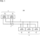
- Fig. 1 is a schematic view illustrating a configuration of an air-conditioning device according to Embodiment 1.
- An air-conditioning device 100 includes a first heat medium circuit 1 through which a first heat medium flows, one or more pumps 2 causing the first heat medium to circulate through the first heat medium circuit 1, one or more heat source devices 3 in the first heat medium circuit 1, and a plurality of load devices 4 in the first heat medium circuit 1.
- the air-conditioning device 100 illustrated in Fig. 1 includes two heat source devices 3 and three load devices 4; however, the number of heat source devices 3 and the number of load devices 4 included in the air-conditioning device 100 are not limited to the illustrated numbers.
- the first heat medium circuit 1 is formed by connecting, by pipes through which the first heat medium flows, the one or more heat source devices 3 and the plurality of load devices 4 through which the first heat medium flows to exchange heat.
- the first heat medium flowing through the first heat medium circuit 1 is, for example, water or brine obtained by adding an additive lowering a freezing point of water to water, and is a substance that is low in GWP and does not have combustibility.
- a heat medium having combustibility may be used as the first heat medium in a certain case.
- the certain case indicates a case where, even when the heat medium leaks, concentration of the heat medium in air does not reach combustion concentration.
- Each of the pumps 2 is an example of circulation generation means that generates a flow of the first heat medium to cause the first heat medium to circulate the first heat medium circuit 1.
- the pumps 2 may be controlled by inverters.
- Each of the heat source devices 3 is, for example, a heat pump chiller, a boiler, or an electric water heater, and cools or heats the first heat medium.
- one of the one or more heat source devices 3 included in the air-conditioning device 100 is defined as a heat source device 3 on a master side
- the other heat source devices 3 are defined as heat source devices 3 on a slave side.
- the one heat source device 3 corresponds to the heat source device 3 on the master side.
- the heat source device 3 on the master side is referred to as a master-side heat source device 3a
- the heat source device 3 on the slave side is referred to as a slave-side heat source device 3b.
- Each of the load devices 4 is disposed inside a room that is an air-conditioned space, and performs air conditioning by exchanging heat between the first heat medium and indoor air.
- the load devices 4 according to Embodiment 1 are classified into the load device 4 on a master side and the load devices 4 on a slave side.
- One of the plurality of load devices 4 included in the air-conditioning device 100 is defined as the load device 4 on the master side (master-side load device), and the other load devices 4 are defined as the load devices 4 on the slave side (slave-side load devices).
- the load device 4 on the master side is referred to as a master-side load device 4a
- the load devices 4 on the slave side are referred to as a slave-side load device 4b and a slave-side load device 4c.
- Fig. 2 is a schematic view illustrating a configuration of each of the heat source devices according to Embodiment 1.
- Each of the heat source devices 3 includes a refrigerant circuit 35 that is formed by sequentially connecting a compressor 30, a flow switching device 31, a heat source-side heat exchanger 32, a decompression device 33, and an intermediate heat exchanger 34 by pipes.
- Refrigerant circulates through the refrigerant circuit 35.
- the refrigerant is an example of a second heat medium
- the refrigerant circuit 35 is an example of a second heat medium circuit. In the refrigerant circuit 35 in the case illustrated in Fig.
- Each of the heat source devices 3 further includes an air-sending device 36 and a heat source-side control device 37.
- the compressor 30 compresses the refrigerant suctioned from a suction side, and discharges high-temperature high-pressure gas refrigerant from a discharge side.
- the flow switching device 31 is a device including, for example, a four-way valve switching the flowing directions of the refrigerant. During the cooling operation, the defrosting operation, and other operation, the flow switching device 31 connects the discharge side of the compressor 30 and the heat source-side heat exchanger 32 and connects the suction side of the compressor 30 and the intermediate heat exchanger 34, as illustrated by solid lines in Fig. 2 .
- the flow switching device 31 connects the discharge side of the compressor 30 and the intermediate heat exchanger 34 and connects the suction side of the compressor 30 and the heat source-side heat exchanger 32, as illustrated by dashed lines in Fig. 2 .
- the heat source-side heat exchanger 32 exchanges heat between the refrigerant and outdoor air.
- the heat source-side heat exchanger 32 is used as a condenser for the refrigerant during the cooling operation and during the defrosting operation, and is used as an evaporator for the refrigerant during the heating operation.
- the air-sending device 36 includes a propeller fan driven by an unillustrated driving source such as a fan motor, guides the outdoor air to the heat source-side heat exchanger 32 inside the corresponding heat source device 3, and sends out the air having exchanged heat with the refrigerant to the outdoors.
- the decompression device 33 includes an expansion valve that decompresses and expands the refrigerant flowing through the refrigerant circuit 35.
- the intermediate heat exchanger 34 exchanges heat between the refrigerant circulating through the refrigerant circuit 35 inside the corresponding heat source device 3 and the first heat medium circulating through the first heat medium circuit 1.
- the first heat medium is cooled at the intermediate heat exchanger 34 during the cooling operation and during the defrosting operation, and the first heat medium is heated at the intermediate heat exchanger 34 during the heating operation.
- the heat source-side control device 37 is connected to the compressor 30, the flow switching device 31, the decompression device 33, the driving source of the air-sending device 36, and other devices by unillustrated signal lines.
- the heat source-side control device 37 controls an operation capacity of the compressor 30, operation to switch the flow paths of the flow switching device 31, a flow rate of the air supplied to the heat source-side heat exchanger 32 by the air-sending device 36, an opening degree of the decompression device 33, and other operation through the signal lines.
- the heat source-side control device 37 is connected to the heat source-side control device 37 of other heat source device 3 through a signal line 5, and performs communication. Note that the heat source-side control devices 37 of all of the heat source devices 3 are not necessarily connected by the signal line 5, and it is sufficient to connect the heat source-side control device 37 of the heat source device 3 on the master side and the heat source-side control device 37 of each of the heat source devices 3 on the slave side.
- the heat source-side control device 37 may be formed by including a processor such as a central processing unit (CPU) and a micro processing unit (MPU), a memory such as a read only memory (ROM) and a random access memory (RAM), and a communication interface.
- a processor such as a central processing unit (CPU) and a micro processing unit (MPU)
- a memory such as a read only memory (ROM) and a random access memory (RAM)
- ROM read only memory
- RAM random access memory
- All or a part of the functions of the heat source-side control device 37 may be performed by dedicated hardware.
- the above-described configuration is common to the heat source device 3 on the master side and the heat source devices 3 on the slave side, unless otherwise noted.
- the heat source-side control device 37 included in the heat source device 3 on the master side is further connected to the pump 2 by a signal line 9, and controls the flow rate of the first heat medium by the pump 2.
- the pump 2 is provided between the intermediate heat exchanger 34 and the load devices 4. The pump 2 causes the first heat medium heated or cooled at the intermediate heat exchanger 34, to flow toward the load devices 4, and causes the first heat medium flowing out from the load devices 4 to flow toward the intermediate heat exchanger 34.
- the heat source-side control device 37 of the heat source device 3 on the master side is connected to a load-side control device 47 of the load device 4 on the master side described below by a signal line 6 (see Fig. 7 ).
- the heat source-side control device 37 of the heat source device 3 on the master side acquires instruction information representing contents instructed to the heat source devices 3 from the load-side control device 47 of the load device 4 on the master side.
- the instruction information is, for example, information representing a heat amount necessary for the load devices 4, or a stop command. The detail of the instruction information is described below.
- the heat source device 3 on the master side uses the instruction information to perform operation instruction to each of the heat source devices 3.
- the heat source-side control device 37 of the heat source device 3 on the master side calculates a control amount to appropriately control the flow rate of the first heat medium by the pump 2, the operation capacity of the compressor 30 to be controlled, and other settings based on the instruction information, and derives control contents to the pump 2, the compressor 30 to be controlled, or other devices from the instruction information. Further, the heat source-side control device 37 of the heat source device 3 on the master side calculates a control amount to appropriately operate the compressor 30, the air-sending device, 36, or other devices included in each of the heat source devices 3 on the slave side based on the instruction information, and derives control contents to the components included in each of the heat source devices 3 on the slave side from the instruction information.
- control amount, the control contents, and other settings to appropriately control the pump 2 and the components included in the heat source device 3 on the master side, obtained from the instruction information by the heat source device 3 on the master side are referred to as first control information.
- control amount, the control contents, and other settings to appropriately control the components included in each of the heat source devices 3 on the slave side, obtained from the instruction information by the heat source device 3 on the master side are referred to as second control information.
- the heat source-side control device 37 of the heat source device 3 on the master side controls the heat source device 3 on the master side and the pump 2 based on the first control information. Further, the heat source-side control device 37 of the heat source device 3 on the master side transmits the second control information to each of the heat source devices 3 on the slave side. In place of acquisition of the first control information and the second control information from the instruction information by the heat source device 3 on the master side, the first control information and the second control information may be included in the instruction information.
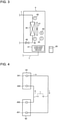
- Fig. 3 is a schematic view illustrating a configuration of each of the load devices according to Embodiment 1.
- Each of the load devices 4 is, for example, an indoor unit that is installed by being embedded in a ceiling of a room or being hung down from the ceiling, and is also referred to as a fan coil unit.
- Each of the load devices 4 includes a load-side heat exchanger 40, an air-sending device 41, an inlet temperature sensor 42, an outlet temperature sensor 43, an indoor temperature sensor 44, an indoor humidity sensor 45, a motor-operated valve 46, and the load-side control device 47.
- Each of the load devices 4 may perform only cooling operation or only heating operation, or may perform the cooling operation and the heating operation in a switchable manner.
- Fig. 4 is a schematic view of the first heat medium circuit in a case where each of the load devices performs only one of the cooling operation and the heating operation.
- the first heat medium circuit 1 is of a two-pipe type, and includes a first pipe 11 through which the first heat medium before cooling or before heating flows and a second pipe 12 through which the first heat medium after cooling or after heating flows.
- the first heat medium before cooling or before heating, flowing out from the load-side heat exchanger 40 flows into the intermediate heat exchanger 34 through the first pipe 11.
- the first heat medium after cooling or after heating, flowing out from the intermediate heat exchanger 34 flows into the load-side heat exchanger 40 through the second pipe 12.
- the intermediate heat exchanger 34 includes an inlet 340 from which the first heat medium before cooling or before heating flows in, and an outlet 341 from which the first heat medium after cooling or after heating flows out.
- the load-side heat exchanger 40 includes an outlet 400 from which the first heat medium before cooling or before heating flows out, and an inlet 401 from which the first heat medium after cooling or after heating flows in.
- Fig. 5 is a schematic view of the first heat medium circuit in a case where each of the load devices performs both of the cooling operation and the heating operation.
- the first heat medium circuit 1 is of a four-pipe type, and includes a third pipe 13 through which the first heat medium before cooling flows, a fourth pipe 14 through which the first heat medium after cooling flows, a fifth pipe 15 through which the first heat medium before heating flows, and a sixth pipe 16 through which the first heat medium after heating flows.
- the first heat medium before cooling, flowing out from the load-side heat exchanger 40 flows into the intermediate heat exchanger 34 through the third pipe 13, and the first heat medium after cooling, flowing out from the intermediate heat exchanger 34 flows into the load-side heat exchanger 40 through the second pipe 12.
- the first heat medium before heating, flowing out from the load-side heat exchanger 40 flows into the intermediate heat exchanger 34 through the fifth pipe 15, and the first heat medium after heating, flowing out from the intermediate heat exchanger 34 flows into the load-side heat exchanger 40 through the sixth pipe 16.
- the intermediate heat exchanger 34 includes an inlet 342 from which the first heat medium before cooling flows in, an outlet 343 from which the first heat medium after cooling flows out, an inlet 344 from which the first heat medium before heating flows in, and an outlet 345 from which the first heat medium after heating flows out.
- the load-side heat exchanger 40 includes an outlet 402 from which the first heat medium before cooling flows out, an inlet 403 from which the first heat medium after cooling flows in, an outlet 404 from which the first heat medium before heating flows out, and an inlet 405 from which the first heat medium after heating flows in.
- the load-side heat exchanger 40 exchanges heat between the first heat medium cooled or heated at the intermediate heat exchanger 34 of each of the heat source devices 3 and air sent into the corresponding load device 4 from inside the room by the air-sending device 41.
- the air-sending device 41 includes a propeller fan driven by, for example, an unillustrated fan motor. The air-sending device 41 guides the indoor air to the load-side heat exchanger 40 inside the corresponding load device 4, and sends the air having exchanged heat with the first heat medium, to inside the room.
- each of the load devices 4 includes the outlet temperature sensor 43 for a case where information on a difference between the temperature of the first heat medium at the inlet and the temperature of the first heat medium at the outlet of the load-side heat exchanger 40 is used by the load-side control device 47 described below in generation of the instruction information.
- each of the load devices 4 may not include the outlet temperature sensor 43.
- the indoor temperature sensor 44 is disposed on windward of the air-sending device 41, and detects a temperature of a room by detecting a temperature of indoor air before heat exchange.
- the temperature of the room is also referred to as an indoor temperature or a room temperature in some cases.
- the indoor humidity sensor 45 is disposed on the windward of the air-sending device 41, and detects an indoor humidity by detecting a humidity of the indoor air before heat exchange.
- Each of the inlet temperature sensor 42, the outlet temperature sensor 43, the indoor temperature sensor 44, and the indoor humidity sensor 45 is an example of detection means.
- the motor-operated valve 46 adjusts an inflow amount of the first heat medium to the load-side heat exchanger 40.
- thermo-on state a state where the load-side heat exchanger 40 exchanges heat between the first heat medium and the indoor air because of the open state of the motor-operated valve 46 and other factors
- thermo-off state a state where the load-side heat exchanger 40 does not exchange heat between the first heat medium and the indoor air because of the closed state of the motor-operated valve 46 and other factors
- the load-side control device 47 is connected to a driving source of the air-sending device 41, the inlet temperature sensor 42, the outlet temperature sensor 43, the indoor temperature sensor 44, the indoor humidity sensor 45, the motor-operated valve 46, and other devices by unillustrated signal lines.
- the load-side control device 47 controls a flow rate of the air supplied to the load-side heat exchanger 40 by the air-sending device 41, opening and closing of the motor-operated valve 46, and other settings.
- the flow rate of the air supplied to the load-side heat exchanger 40 by the air-sending device 41 and the flow rate of the air sent to outside the room by the air-sending device 41 are each referred to as an air volume.
- the motor-operated valve 46 may be put into any one of one opened state and one closed state by opening-closing control (on-off control) by the load-side control device 47, or an opening degree of the motor-operated valve 46 may be controlled by proportional control by the load-side control device 47.
- the load-side control device 47 can detect whether the air-sending device 41 is operating, and can detect the air volume in a case where the air-sending device 41 is operating. Further, to control opening and closing of the motor-operated valve 46 and other operation, the load-side control device 47 can detect the opened and closed state of the motor-operated valve 46. Therefore, a portion of the load-side control device 47 that detects execution and non-execution of the operation of the air-sending device 41, the air volume by the air-sending device 41, the opening and closing of the motor-operated valve 46, and other operation is an example of the detection means.
- Each of the load devices 4 is provided with a remote controller (remote control) 48 that is connected to the corresponding load-side control device 47 in a wired or wireless manner.
- the remote control 48 receives an instruction from a user, and transmits the instruction to the load-side control device 47.
- the load-side control device 47 controls the corresponding load device 4 based on contents of the instruction from the remote control 48.
- the contents of the instruction from the remote control 48 indicate a start command or a stop command of the air-conditioning operation, a set temperature, the air volume by the air-sending device 41, and other settings.
- the remote control 48 is an example of the detection means.
- the load-side control device 47 opens or closes the motor-operated valve 46 based on a difference between a value of the set temperature set by the remote control 48 connected to the load-side control device 47 and a value of the indoor temperature detected by the indoor temperature sensor 44. In contrast, during the heating operation, the load-side control device 47 opens or closes the motor-operated valve 46 based on a difference between the value of the indoor temperature and the value of the set temperature.
- Fig. 6 is a diagram illustrating an outline of control contents of the motor-operated valve by the load-side control device according to Embodiment 1.
- a value T represents "value of set temperature - value of indoor temperature” during the cooling operation, and represents "value of indoor temperature - value of set temperature” during the heating operation.
- the following description is given of a case where the motor-operated valve 46 is put into any one of one opened state and one closed state, to facilitate understanding.
- the load-side control device 47 controls the motor-operated valve 46 such that the motor-operated valve 46 is switched from the opened state to the closed state.
- the motor-operated valve 46 is put into the closed state during the cooling operation, the first heat medium cooled by the heat source devices 3 does not flow into the corresponding load device 4. Therefore, the heat exchange between the cooled first heat medium and the indoor air is not performed, and lowering of the indoor temperature is stopped.
- the load-side control device 47 controls the motor-operated valve 46 such that the motor-operated valve 46 is switched to the opened state again.
- the load-side control device 47 controls the motor-operated valve 46 such that the motor-operated valve 46 is switched from the opened state to the closed state.
- the motor-operated valve 46 is put into the closed state during the heating operation, the first heat medium heated by the heat source devices 3 does not flow into the corresponding load device 4. Therefore, the heat exchange between the heated first heat medium and the indoor air is not performed, and increase of the indoor temperature is stopped.
- the load-side control device 47 controls the motor-operated valve 46 such that the motor-operated valve 46 is switched to the opened state again.
- the control of the motor-operated valve 46 in each of the load devices 4 described above is not to control the heat source devices 3. Therefore, even in the case where the room temperature becomes less than the set temperature during the cooling operation or even in the case where the room temperature becomes greater than the set temperature during the heating operation, the compressor 30, the air-sending device 36, or other devices in each of the heat source devices 3 may continue the operation, and the power may be wastefully consumed.
- the processing in the load devices 4 brings about change in the heat source devices 3 to achieve both energy saving and comfortableness of the air-conditioned space is described.
- the load-side control device 47 acquires information representing detection contents from each of the inlet temperature sensor 42, the outlet temperature sensor 43, the indoor temperature sensor 44, and the indoor humidity sensor 45.
- at least one of the inlet temperature sensor 42, the outlet temperature sensor 43, the indoor temperature sensor 44, and the indoor humidity sensor 45 are referred to as various kinds of sensors in some cases.
- Information including at least one of information representing the detection results of the various kinds of sensors, information representing the contents of the instruction from the user detected by the remote control 48, information representing execution and non-execution of the operation of the air-sending device 41, information representing the air volume by the air-sending device 41, and information representing the opening and closing of the motor-operated valve 46, and the other information is referred to as detection information.
- the detection information may include information representing whether the corresponding load device 4 is performing the air-conditioning operation.
- the detection information represents an operation state of each of the load devices 4. The reason is described below.
- the load-side control device 47 controls the operation of the corresponding load device 4 by using the information representing the detection results of the various kinds of sensors, the information representing the instruction contents through the remote control 48, or other information in the detection information. Therefore, the detection information such as the information representing the detection results of the various kinds of sensors and the information representing the instruction contents through the remote control 48 represents the operation state of the corresponding load device 4 at or after the current time point by the control of the load-side control device 47. Further, the detection information such as the information representing execution and non-execution of the operation of the air-sending device 41, the information representing the air volume by the air-sending device 41, and the information representing the opening and closing of the motor-operated valve 46 represents the operation state of the corresponding load device 4 at the current time point.
- the load-side control device 47 is connected to the load-side control devices 47 of the other load devices 4 through signal lines 7, for example, for transmission and reception of the detection information. Note that the load-side control devices 47 of all of the load devices 4 are not necessarily connected to one another by the signal lines 7, and it is sufficient to connect the load-side control device 47 of the load device 4 on the master side to the load-side control device 47 of each of the load devices 4 on the slave side.
- the load-side control device 47 may be formed by including a processor such as a CPU and an MPU, a memory such as ROM and RAM, and a communication interface. When the processor executes various kinds of programs stored in the memory, the above-described operation is performable. Note that all or a part of the functions of the load-side control device 47 may be performed by dedicated hardware.
- the above-described configuration is common to the load device 4 on the master side and the load devices 4 on the slave side, unless otherwise noted.
- the load-side control device 47 of the load device 4 on the master side stores an operation capacity of each of the load devices 4 and the total number of load devices 4 on the slave side.
- the load-side control device 47 included in the load device 4 on the master side acquires the detection information acquired by the load-side control device 47 of each of the load devices 4 on the slave side.
- This acquisition may be performed when the detection information is transmitted from at least one load device 4 on the slave side to the load device 4 on the master side in a case where change of the set temperature or the operation state is commanded through operation of the remote control 48 by the user in the at least one load device 4 on the slave side or in a case where change of the indoor temperature or the temperature of the first heat medium is detected.
- the load device 4 on the master side may acquire the detection information in response to the fact that a request to acquire the detection information is regularly issued from the load device 4 on the master side to each of the load devices 4 on the slave side.
- the detection information transmitted from each of the load devices 4 on the slave side to the load device 4 on the master side may be detection information obtained in such a manner that the load-side control device 47 of each of the load devices 4 on the slave side performs processing on the detection information acquired from the various kinds of sensors, for simplification of the processing in the load-side control device 47 of the load device 4 on the master side.
- the load-side control device 47 of the master-side load device 4a generates the instruction information representing contents requested for the heat source devices 3, based on the acquired detection information.
- the instruction information may be information representing the contents requested collectively for all or a part of the heat source device 3, or information representing contents requested for each of all or a part of the heat source devices 3.
- the instruction information includes information representing a heat amount requested to be generated by all or a part of the heat source devices 3 or each of the heat source devices 3, information representing an instruction to start or stop operation of the components included in all or a part of the heat source devices 3 or each of the heat source devices 3, information representing a control amount for the heat source-side control device 37 to control the components included in all or a part of the heat source devices 3 or each of the heat source devices 3, and information representing the flow rate of the first heat medium by the pump 2.
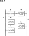
- Fig. 7 is a diagram schematically illustrating a circuit configuration of the signal lines connecting the one or more heat source devices and the plurality of load devices according to Embodiment 1.
- Fig. 7 schematically illustrates the circuit configuration of the signal lines in the air-conditioning device 100 illustrated in Fig. 1 .
- the master-side load device 4a is connected to each of the slave-side load device 4b and the slave-side load device 4c by the signal lines 7.
- the detection information is transmitted from each of the slave-side load device 4b and the slave-side load device 4c to the master-side load device 4a through the signal lines 7.
- the master-side load device 4a and the master-side heat source device 3a are connected by the signal line 6.
- the instruction information is transmitted from the master-side load device 4a to the master-side heat source device 3a through the signal line 6. Furthermore, the master-side heat source device 3a and the slave-side heat source device 3b are connected by the signal line 5. The second control information is transmitted from the master-side heat source device 3a to the slave-side heat source device 3b through the signal line 5.
- Fig. 8 is a flowchart illustrating an example of operation of the load devices and operation of the heat source devices interlocked with the operation of the load devices according to Embodiment 1.
- step S1 at least one of the load devices 4 performs air-conditioning operation.
- step S2 NO in step S2
- the processing by the air-conditioning device 100 returns to step S1.
- the load-side control device 47 of the load device 4 on the master side In a case where all of the load devices 4 stop the air-conditioning operation, for example, in response to operation of the respective remote controls 48 in step S2 (YES in step S2), the load-side control device 47 of the load device 4 on the master side generates the instruction information based on the detection information representing stop of the air-conditioning operation of all of the load devices 4 in step S3.
- the instruction information is information representing the contents instructed to the heat source devices 3, corresponding to stop of the air-conditioning operation of all of the load devices 4.
- the load device 4 on the master side transmits the generated instruction information to the heat source device 3 on the master side.
- step S4 the heat source device 3 on the master side stops operation of the compressor 30 of the heat source device 3 on the master side and stops operation of the pump 2 based on the first control information from the instruction information received from the load device 4 on the master side. Further, in step S4, the heat source device 3 on the master side transmits the second control information from the instruction information to each of the heat source devices 3 on the slave side. In step S4, each of the heat source devices 3 on the slave side stops operation of the compressor 30 of the heat source device 3 on the slave side based on the second control information received from the heat source device 3 on the master side. As a result, the compressors 30 of all of the heat source devices 3 stop operation, and the pump 2 also stops operation.
- Fig. 9 is a flowchart illustrating another example of the operation of the load devices and the operation of the heat source devices interlocked with the operation of the load devices according to Embodiment 1.
- step S11 at least one of the load devices 4 is in the thermo-on state.
- step S12 NO in step S12
- the processing by the air-conditioning device 100 returns to step S11.
- step S12 the load-side control device 47 of the load device 4 on the master side generates the instruction information based on the detection information representing the thermo-off states of all of the load devices 4 in step S13.
- the instruction information is information representing the contents instructed to the heat source devices 3, corresponding to the thermo-off states of all of the load devices 4.
- step S13 the load device 4 on the master side transmits the generated instruction information to the heat source device 3 on the master side.
- step S14 the heat source device 3 on the master side stops the operation of the compressor 30 of the heat source device 3 on the master side, and controls and minimizes the flow rate of the first heat medium by the pump 2, based on the first control information from the instruction information received from the load device 4 on the master side. The minimum flow rate is previously determined. Further, in step S14, the heat source device 3 on the master side transmits the second control information from the instruction information to each of the heat source devices 3 on the slave side. In step S14, each of the heat source devices 3 on the slave side stops the operation of the compressor 30 of the heat source device 3 on the slave side based on the second control information received from the heat source device 3 on the master side. As a result, the compressors 30 of all of the heat source devices 3 stop operation.
- Fig. 10 is a flowchart illustrating control processing corresponding to loads of the load devices, by the air-conditioning device according to Embodiment 1.
- the air-conditioning device 100 performs the air-conditioning operation.
- the load device 4 on the master side acquires the detection information from each of the load devices 4 on the slave side.
- step S23 the load-side control device 47 of the load device 4 on the master side calculates a ratio of a current load amount to a total load amount.
- the total load amount is a sum of load amounts obtained by quantifying loads applied to the respective load devices 4 in a case where all of the load devices 4 perform operation at a maximum.
- the current load amount is a sum of load amounts obtained by quantifying loads applied to the respective load devices 4 operating at the current time point.
- the load-side control device 47 of the load device 4 on the master side stores the operation capacity of each of the load device 4 on the master side and the load devices 4 on the slave side.
- the load-side control device 47 of the load device 4 on the master side stores a number representing the operation capacity by the air-sending device 41 of each of the load device 4 on the master side and the load devices 4 on the slave side.
- numbers representing the operation capacities of the air-sending devices 41 of the master-side load device 4a, the slave-side load device 4b, and the slave-side load device 4c are respectively 800, 300, and 400.
- a load amount representing a load applied to each of the air-sending devices 41 is described as an example of the load amount.
- the current load amount is the number 300 that represents the capacity of the air-sending device 41 of the slave-side load device 4b.
- the total load amount is the sum of the numbers 800, 300, and 400 representing the capacities of the respective air-sending devices 41 of the master-side load device 4a, the slave-side load device 4b, and the slave-side load device 4c, namely, 1500.
- the ratio of the current load amount to the total load amount is 0.2 relative to the total load amount of 1.
- step S23 the load-side control device 47 of the load device 4 on the master side determines whether the ratio of the current load amount to the total load amount is less than or equal to a predetermined first threshold. In a case where the ratio of the current load amount to the total load amount is less than or equal to the first threshold (YES in step S23), the processing by the load device 4 on the master side proceeds to step S24. In a case where the ratio of the current load amount to the total load amount is greater than the first threshold (NO in step S23), the air-conditioning device 100 returns to the original state in step S21.
- step S24 the load-side control device 47 of the load device 4 on the master side generates the instruction information based on the ratio of the current load amount to the total load amount calculated from the acquired detection information and the operation capacities of the respective load devices 4, and transmits the generated instruction information to the heat source device 3 on the master side.
- the instruction information at this time instructs each of the heat source devices 3 to control the temperature of the first heat medium flowing out from each of the heat source devices 3.
- the instruction information instructs increase of the temperature of the first heat medium flowing out from each of the heat source devices 3 by a predetermined temperature, for example, 1 degree C.
- the instruction information instructs increase of an evaporating temperature of the refrigerant, and is to control the compressor 30, the decompression device 33, or other devices such that a pressure of the refrigerant in a low-pressure state is increased. This is to reduce energy consumed during the cooling operation.
- the instruction information may instruct further increase of the temperature of the first heat medium flowing out from each of the heat source devices 3.
- the instruction information instructs decrease of the temperature of the first heat medium flowing out from each of the heat source devices 3 by a predetermined temperature.
- step S25 the heat source device 3 on the master side controls the compressor 30, the decompression device 33, or other devices of the heat source device 3 on the master side such that the temperature and the pressure of the refrigerant and other factors are controlled, based on the first control information from the instruction information received from the load device 4 on the master side. Further, in step S25, the heat source device 3 on the master side transmits the second control information from the instruction information to each of the heat source devices 3 on the slave side.
- each of the heat source devices 3 on the slave side controls the compressor 30, the decompression device 33, or other devices of the heat source device 3 on the slave side such that the temperature and the pressure of the refrigerant and other factors are controlled based on the second control information received from the heat source device 3 on the master side. For example, during the cooling operation, each of the heat source devices 3 exercises control to increase the evaporating temperature of the refrigerant.
- the load-side control device 47 of the load device 4 on the master side acquires the detection information representing the operation state of each of the plurality of load devices 4 included in the air-conditioning device 100, detected by the detection means of each of the plurality of load devices 4. Further, the load-side control device 47 of the load device 4 on the master side uses the acquired detection information to generate the instruction information representing the contents instructed to the one or more heat source device 3 included in the air-conditioning device 100, and transmits the instruction information to the heat source device 3 on the master side.
- the heat source device 3 on the master side having received the instruction information controls at least any of all or a part of the one or more heat source devices 3 and the pump 2, based on the instruction information. As a result, the heat source devices 3 can perform the operation corresponding to the operation states of the load devices 4, which makes it possible to improve air-conditioning efficiency.
- the heat source device 3 on the master side generates the first control information to control the heat source device 3 on the master side and the second control information to control each of the heat source devices 3 on the slave side, based on the instruction information received from the load-side control device 47 of the load device 4 on the master side. Further, the heat source device 3 on the master side controls at least one of the heat source device 3 on the master side and the pump 2 based on the first control information, and transmits the second control information to each of the heat source devices 3 on the slave side. Each of the heat source devices 3 on the slave side controls the heat source device 3 on the slave side based on the received second control information. As a result, the heat source devices 3 can perform the operation corresponding to the operation states of the load devices 4, which makes it possible to improve air-conditioning efficiency.
- the load-side control device 47 of the load device 4 on the master side generates the instruction information representing an instruction to stop the operation of all of the one or more heat source device 3 and the operation of the pump 2.
- the operation of the heat source devices 3 and the operation of the pump 2 are stopped by interlocking with the stop operation of the load devices 4.
- the load-side control device 47 of the load device 4 on the master side generates the instruction information representing an instruction to stop the operation of all of the heat source devices 3 and an instruction to minimize the flow rate of the first heat medium by the pump 2.
- the instruction information it is possible to stop wasteful operation to heat or cool the first heat medium by the heat source devices 3 under a situation where none of the load devices 4 perform the heat exchange between the first heat medium and the indoor air, which makes it possible to reduce wasteful energy consumption by the operation of the heat source devices 3 and the operation of the pump 2.
- the load-side control device 47 of the load device 4 on the master side stores the information representing the operation capacity of each of the load devices 4.
- the load-side control device 47 of the load device 4 on the master side calculates the current load amount that is the sum of load amounts obtained by quantifying the loads applied to the respective load devices 4 operating at the current time point, based on the detection information detected by the detection means of each of the load devices 4.
- the load-side control device 47 of the load device 4 on the master side calculates the total load amount obtained by quantifying the loads applied to the respective load devices 4 in the case where all of the load devices 4 perform operation at a maximum, by using the information representing the operation capacity of each of the load devices 4.
- the load-side control device 47 of the load device 4 on the master side In the case where the air-conditioning operation is the cooling operation and in the case where the ratio of the current load amount to the total load amount is less than or equal to the first threshold, the load-side control device 47 of the load device 4 on the master side generates the instruction information to instruct increase of the temperature of the first heat medium flowing out from each of the heat source devices 3 by a predetermined temperature. In the case where the air-conditioning operation is the heating operation and in the case where the ratio of the current load amount to the total load amount is less than or equal to the first threshold, the load-side control device 47 of the load device 4 on the master side generates the instruction information to instruct decrease of the temperature of the first heat medium flowing out from each of the heat source devices 3 by a predetermined temperature. In the case where the current load amount is small, the processing by the heat source devices 3 can be reduced in response to the instruction information, which makes it possible to reduce wasteful energy consumption.
- the air-conditioning device 100 according to Embodiment 1 can perform the cooling operation and the heating operation, which makes it possible to improve comfortableness of the user.
- the load-side control device 47 of the load device 4 on the master side in Embodiment 1 described above calculates the current load amount and the total load amount, and in the case where the value obtained by dividing the current load amount by the total load amount is less than or equal to the first threshold, the load-side control device 47 of the load device 4 on the master side generates the instruction information to instruct control of the temperature of the first heat medium flowing out from each of the heat source devices 3.
- the load-side control device 47 of the load device 4 on the master side in the air-conditioning device 100 according to Embodiment 2 generates the instruction information to reduce wasteful operation of the compressor 30, the decompression device 33, and other devices without performing calculation of the current load amount and the total load amount, and division.
- descriptions of parts similar to the parts in Embodiment 1 described above are omitted, unless otherwise noted.
- the load-side control device 47 of the load device 4 on the master side calculates a difference between the value of the detected indoor temperature in each of the plurality of load devices 4 and the value of the set temperature by the remote control 48 in each of the plurality of load devices 4.
- the load-side control device 47 of the load device 4 on the master side generates the instruction information instructing each of the heat source devices 3 to increase the temperature of the first heat medium flowing out from each of the heat source devices 3 by a predetermined temperature.
- the load-side control device 47 of the load device 4 on the master side generates the instruction information instructing each of the heat source devices 3 to decrease the temperature of the first heat medium flowing out from each of the heat source devices 3 by a predetermined temperature.
- the predetermined temperature is, for example, 1 degree C as in the above description.
- the second threshold is, for example, one.
- the load-side control device 47 of the load device 4 on the master side may store or may not store the operation capacity of each of the load devices 4.
- Fig. 11 is a flowchart illustrating control processing based on the difference between the set temperature and the indoor temperature, by the air-conditioning device according to Embodiment 2.
- the air-conditioning device 100 performs the air-conditioning operation.
- the load device 4 on the master side acquires the detection information from each of the load devices 4 on the slave side.
- the detection information includes information representing the indoor temperature detected by the indoor temperature sensor 44 and information representing the set temperature input by the user through the remote control 48.
- step S33 the load-side control device 47 of the load device 4 on the master side calculates the absolute value of the difference between the value of the indoor temperature and the value of the set temperature, represented by the detection information acquired in step S32.
- the absolute value of the difference between the value of the indoor temperature and the value of the set temperature may be calculated by each of the load devices 4 detecting the indoor temperature and the set temperature, in place of the load-side control device 47 of the load device 4 on the master side.
- the detection information in this case may include the difference between the value of the indoor temperature and the value of the set temperature, calculated by each of the load devices 4, or the absolute value of the difference.
- step S33 the load-side control device 47 of the load device 4 on the master side determines whether the absolute value of the difference obtained from the detection information detected in each of the load devices 4 is less than or equal to the second threshold. In a case where the absolute value of the difference is less than or equal to the second threshold (YES in step S33), the processing by the load device 4 on the master side proceeds to step S34. In a case where the absolute value of the difference is greater than the second threshold (NO in step S33), the air-conditioning device 100 returns to an original state in step S31.
- step S34 the processing by the load-side control device 47 of the load device 4 on the master side may proceed to step S34 not in the case where the absolute value of the difference obtained from the detection information detected in each of the load devices 4 is less than or equal to the second threshold but in a case where the absolute value of the difference obtained from the detection information detected in each of a predetermined number or more of load devices 4 is less than or equal to the second threshold.
- step S34 the load-side control device 47 of the load device 4 on the master side generates the instruction information instructing control of the temperature of the first heat medium flowing out from each of the heat source devices 3, and transmits the generated instruction information to the heat source device 3 on the master side.
- the instruction information at this time instructs increase of the temperature of the first heat medium flowing out from each of the heat source devices 3, by a predetermined temperature.
- the instruction information at this time instructs decrease of the temperature of the first heat medium flowing out from each of the heat source devices 3, by a predetermined temperature.
- step S35 the heat source device 3 on the master side controls the compressor 30, the decompression device 33, or other devices of the heat source device 3 on the master side such that the temperature and the pressure of the refrigerant and other factors are controlled, based on the first control information from the instruction information received from the load device 4 on the master side. Further, in step S35, the heat source device 3 on the master side transmits the second control information from the instruction information to each of the heat source devices 3 on the slave side.
- each of the heat source devices 3 on the slave side controls the compressor 30, the decompression device 33, or other devices of the heat source device 3 on the slave side such that the temperature and the pressure of the refrigerant and other factors are controlled, based on the second control information received from the heat source device 3 on the master side. For example, during the cooling operation, each of the heat source devices 3 exercises control to increase the evaporating temperature of the refrigerant.
- the air-conditioning device 100 according to Embodiment 2 can reduce the calculation processing by the load-side control device 47 of the load device 4 on the master side.
- the air-conditioning device 100 in Embodiment 2 described above controls the temperature of the first medium flowing out from each of the heat source devices 3 in the case where the absolute value of the difference between the value of the indoor temperature and the value of the set temperature, represented by the detection information detected by the detection means of each of the load devices 4 is less than or equal to the second threshold.
- the air-conditioning device 100 according to Embodiment 3 controls the temperature of the first medium flowing out from each of the heat source devices 3 by also using information representing a humidity in the air-conditioned space.
- the detection information in Embodiment 3 includes the information representing the indoor temperature and the information representing the set temperature as in Embodiment 2 described above.
- the detection information in Embodiment 3 further includes information representing a humidity of a room (indoor humidity) detected by the indoor humidity sensor 45.
- the load-side control device 47 of the load device 4 on the master side calculates the difference between the value of the detected indoor humidity in each of the plurality of load devices 4 and the value of the set temperature by the remote control 48 in each of the plurality of load devices 4.
- the load-side control device 47 of the load device 4 on the master side generates the instruction information instructing each of the heat source devices 3 to increase the temperature of the first heat medium flowing out from each of the heat source devices 3 by a predetermined temperature.
- the load-side control device 47 of the load device 4 on the master side generates the instruction information instructing each of the heat source devices 3 to decrease the temperature of the first heat medium flowing out from each of the heat source devices 3 by a predetermined temperature.
- the predetermined temperature is, for example, 1 degree C as in the above description.
- the third threshold is, for example, a value corresponding to a relative humidity of 50%.
- the load-side control device 47 of the load device 4 on the master side may store or may not store the operation capacity of each of the load devices 4, as in Embodiment 2 described above.
- the load-side control device 47 of the load device 4 on the master side in Embodiment 3 does not instruct each of the heat source devices 3 to control the temperature of the first heat medium flowing out from each of the heat source devices 3.
- the reason is as follows. For example, in a case where the air-conditioning device 100 performs the cooling operation on a space with high humidity, the air-conditioning device 100 cools the air while changing water vapor in the air to water, in phase. In this case, it is necessary for the air-conditioning device 100 to remove heat including latent heat of the water vapor.
- the air-conditioning device 100 is required to exert cooling capacity more than that in a case where the indoor humidity is low. Therefore, in the case where the indoor humidity is greater than the third threshold, the above-described control is not performed.
- Fig. 12 is a flowchart illustrating control processing based on the set temperature, the indoor temperature, and the indoor humidity, by the air-conditioning device according to Embodiment 3.
- the air-conditioning device 100 performs the air-conditioning operation.
- the load device 4 on the master side acquires the detection information from each of the load devices 4 on the slave side.
- the detection information includes the information representing the indoor temperature detected by the indoor temperature sensor 44, the information representing the set temperature input by the user through the remote control 48, and the information representing the indoor humidity detected by the indoor humidity sensor 45.
- step S43 the load-side control device 47 of the load device 4 on the master side calculates the absolute value of the difference between the value of the indoor temperature and the value of the set temperature, represented by the detection information acquired in step S42.
- the absolute value of the difference between the value of the indoor temperature and the value of the set temperature may be calculated by each of the load devices 4 detecting the indoor temperature and the set temperature, in place of the load-side control device 47 of the load device 4 on the master side.
- the detection information in this case may include the difference between the value of the indoor temperature and the value of the set temperature, calculated by each of the load devices 4, or the absolute value of the difference.
- step S43 the load-side control device 47 of the load device 4 on the master side determines whether the absolute value of the difference obtained from the detection information detected in each of the load devices 4 is less than or equal to the second threshold. In a case where the absolute value of the difference is less than or equal to the second threshold (YES in step S43), the processing by the load device 4 on the master side proceeds to step S44. In a case where the absolute value of the difference is greater than the second threshold (NO in step S43), the air-conditioning device 100 returns to an original state in step S41.
- the processing of the load-side control device 47 of the load device 4 on the master side may proceed to step S44 not in the case where the absolute value of the difference obtained from the detection information detected in each of the load devices 4 is less than or equal to the second threshold but in a case where the absolute value of the difference obtained from the detection information detected in each of a predetermined number or more of load devices 4 is less than or equal to the second threshold.
- step S44 the load-side control device 47 of the load device 4 on the master side determines whether the value of the indoor humidity represented by the detection information detected in each of the load devices 4 is less than or equal to the third threshold. In a case where the value of the indoor humidity is less than or equal to the third threshold (YES in step S44), the processing by the load device 4 on the master side proceeds to step S45. In a case where the absolute value of the difference is greater than the third threshold (NO in step S44), the air-conditioning device 100 returns to the original state in step S41.
- step S45 the load-side control device 47 of the load device 4 on the master side generates the instruction information instructing control of the temperature of the first heat medium flowing out from each of the heat source devices 3, and transmits the generated instruction information to the heat source device 3 on the master side.
- the instruction information at this time instructs increase of the temperature of the first heat medium flowing out from each of the heat source devices 3 by a predetermined temperature.
- the instruction information at this time instructs decrease of the temperature of the first heat medium flowing out from each of the heat source devices 3 by a predetermined temperature.
- step S46 the heat source device 3 on the master side controls the compressor 30, the decompression device 33, or other devices of the heat source device 3 on the master side such that the temperature and the pressure of the refrigerant and other factors are controlled, based on the first control information from the instruction information received from the load device 4 on the master side. Further, in step S46, the heat source device 3 on the master side transmits the second control information from the instruction information to each of the heat source devices 3 on the slave side.
- each of the heat source devices 3 on the slave side controls the compressor 30, the decompression device 33, or other devices of the heat source device 3 on the slave side such that the temperature and the pressure of the refrigerant and other factors are controlled, based on the second control information received from the heat source device 3 on the master side. For example, during the cooling operation, each of the heat source devices 3 exercises control to increase the evaporating temperature of the refrigerant.
- Embodiment 3 performs the control using the indoor humidity in addition to the indoor temperature and the set temperature, it is possible to reduce wasteful energy consumption while maintaining comfortableness.
- the air-conditioning device 100 according to Embodiment 4 performs instruction to each of the heat source devices 3 based on each of cooling capacity and heating capacity in addition to the configuration and operation by the air-conditioning device 100 according to Embodiments 1 to 3 described above, and wasteful energy consumption is thus reduced.
- descriptions of parts similar to the parts in Embodiments 1 to 3 described above are omitted, unless otherwise noted.
- Each of the cooling capacity and the heating stress is a product of the value of the difference between the indoor temperature and the temperature of the first heat medium, and the flow rate of the first heat medium.
- the temperature of the first heat medium is determined based on the indoor temperature or based on whether the air-conditioning operation is the cooling operation or the heating operation. For example, in the case where the indoor temperature is 27 degrees C during the cooling operation, the air-conditioning operation is often performed while the temperature of the first heat medium flowing out from each of the heat source devices 3 is set to, for example, 7 degrees C.
- the air-conditioning operation is often performed while the temperature of the first heat medium flowing out from each of the heat source devices 3 is set to, for example, 45 degrees C.
- the difference between the indoor temperature and the temperature of the first heat medium is 20 degrees C during the cooling operation and is 25 degrees C during the heating operation.
- the value of the difference between the indoor temperature and the temperature of the first heat medium during the heating operation is often greater than the value of the difference between the indoor temperature and the temperature of the first heat medium during the cooling operation.
- the flow rate of the first heat medium during the cooling operation and the flow rate of the first heat medium during the heating operation are equal to each other in many cases. Accordingly, the heating capacity is often higher than the cooling capacity.
- the cooling capacity and the heating capacity necessary for comfortableness of the user are not different from each other, and the energy is often wastefully used during the heating operation more than during the cooling operation.
- the air-conditioning device 100 makes the flow rate of the first heat medium by the pump 2 during the heating operation lower than the preset flow rate (set flow rate), and wasteful energy consumption is thus reduced.
- the load-side control device 47 of the load device 4 on the master side changes the value of the flow rate of the first heat medium during the heating operation from the value of the set flow rate, based on the indoor temperature or the temperature of the first heat medium.
- the load-side control device 47 of the load device 4 on the master side instructs each of the heat source devices 3 to control the value of the flow rate of the first heat medium during the heating operation such that the flow rate is a flow rate of a value obtained by multiplying the value of the set flow rate by a numerical value determined based on the indoor temperature.
- the numerical value is a value obtained by dividing a difference between a predicted value of the indoor temperature and the value of the temperature of the first heat medium during the cooling operation by the difference between the temperature of the first heat medium and the indoor temperature during the heating operation. Note that the predicted value of the indoor temperature during the cooling operation is previously determined.
- Fig. 13 is a flowchart illustrating control processing of the flow rate of the first heat medium during the heating operation, by the air-conditioning device according to Embodiment 4.
- the air-conditioning device 100 performs the air-conditioning operation.
- the load device 4 on the master side acquires the detection information from each of the load devices 4 on the slave side.
- the detection information includes information representing any of the heating operation and the cooling operation detected by the remote control 48.
- the detection information represents whether the corresponding load device 4 performs the heating operation or the cooling operation.
- step S53 the load-side control device 47 of the load device 4 on the master side determines whether the detection information acquired in step S52 is information indicating that the operation by the air-conditioning device 100 is the heating operation. In a case where the operation by the air-conditioning device 100 is the heating operation (YES in step S53), the processing by the load device 4 on the master side proceeds to step S54. In a case where the operation by the air-conditioning device 100 is not the heating operation (NO in step S53), the air-conditioning device 100 returns to an original state in step S51.
- step S54 the load-side control device 47 of the load device 4 on the master side generates the instruction information instructing control of the flow rate of the first heat medium flowing out from each of the heat source devices 3, and transmits the generated instruction information to the heat source device 3 on the master side.
- the instruction information at this time is to control the pump 2 such that the flow rate of the first heat medium is reduced.
- step S55 the heat source device 3 on the master side controls the pump 2, based on the first control information from the instruction information received from the load device 4 on the master side, such that the flow rate of the first heat medium by the pump 2 is reduced.
- the air-conditioning device 100 according to Embodiment 4 can reduce unnecessary energy consumption by reducing the flow rate of the first heat medium during the heating operation.
- the air-conditioning device 100 according to Embodiment 4 reduces the flow rate of the first heat medium during the heating operation by using the value of the temperature of the first heat medium and the predicted value of the indoor temperature during the cooling operation, in addition to the value of the temperature of the first heat medium and the value of the indoor temperature during the heating operation. This makes it possible to maintain comfortableness and to achieve energy saving.
- the air-conditioning device 100 according to Embodiment 5 further achieves maintenance of comfortableness by defrosting operation, in addition to the configuration and operation by the air-conditioning devices 100 according to Embodiments 1 to 4 described above.
- descriptions of parts similar to the parts in Embodiments 1 to 4 described above are omitted, unless otherwise noted.
- the heat source-side heat exchanger 32 of each of the heat source devices 3 is frosted in a case where the outdoor temperature outside the air-conditioned space is low during the heating operation. This lowers the heating capacity of the air-conditioning device 100. Therefore, periodic defrosting is necessary. For example, in many cases, defrosting operation is performed by causing hot gas to flow through the heat source-side heat exchanger 32 and switching operation by the flow switching device 31. In this case, the first heat medium circuit 1 is cooled at the intermediate heat exchanger 34, and the heating operation by the air-conditioning device 100 is accordingly stopped. As a result, the air-conditioning device 100 temporarily performs the cooling operation. Accordingly, during this period, cold air is blown out from the air-sending device 41 of each of the load devices 4.
- the load-side control device 47 of the load device 4 on the master side acquires information representing the defrosting operation from the heat source-side control device 37 of the heat source device 3 on the master side through the signal line 6.
- the load-side control device 47 of the load device 4 on the master side having received the information representing the defrosting operation reduces the air volume by the air-sending device 41 of each of the load devices 4, to a predetermined minimum air volume.
- Fig. 14 is a flowchart illustrating control processing during the defrosting operation, by the air-conditioning device according to Embodiment 5.
- step S61 the air-conditioning device 100 performs the air-conditioning operation.
- step S62 in a case where the load device 4 on the master side receives information indicating that each of the heat source devices 3 performs the defrosting operation, from the heat source device 3 on the master side (YES in step S62), the processing proceeds to step S63.
- step S62 in a case where the load device 4 on the master side does not receive the information indicating that each of the heat source devices 3 performs the defrosting operation, from the heat source device 3 on the master side (NO in step S62), the air-conditioning device 100 returns to an original state in step S61.
- step S63 the load-side control device 47 of the load device 4 on the master side controls the air volume by the air-sending device 41 of the load device 4 on the master side such that the air volume is reduced to the minimum air volume.
- step S63 the load-side control device 47 of the load device 4 on the master side transmits an instruction to control the air volume by the air-sending device 41 of each of the load devices 4 on the slave side such that the air volume is reduced to the minimum air volume, to the load-side control device 47 of each of the load devices 4 on the slave side through the signal lines 7.
- the load-side control device 47 of each of the load devices 4 on the slave side having received the instruction controls the air volume by the air-sending device 41 of the load device 4 on the slave side such that the air volume is reduced to the minimum air volume.
- the load-side control device 47 of each of the load devices 4 controls the corresponding air-sending device 41 such that the volume of air to be sent is minimized while each of the heat source devices 3 performs the defrosting operation. As a result, it is possible to reduce wasteful energy consumption without impairing comfortableness of the user.
- the air-conditioning device 100 according to Embodiment 6 further achieves improvement of comfortableness during the defrosting operation, in addition to the configuration and operation by the air-conditioning device 100 according to Embodiment 5 described above.
- descriptions of parts similar to the parts in Embodiments 1 to 5 described above are omitted, unless otherwise noted.
- the heat source-side heat exchanger 32 is frosted, and periodic defrosting is necessary. During the defrosting operation, however, as described above, cold air is blown out from each of the load devices 4, which impairs comfortableness.
- the air-conditioning device 100 according to Embodiment 5 described above minimizes the air volume by the air-sending device 41 during the defrosting operation, whereas the air-conditioning device 100 according to Embodiment 6 previously increases the indoor temperature before the defrosting operation, to further improve comfortableness during the defrosting operation. A detailed description is given below.
- At least one of the heat source device 3 on the master side and the load device 4 on the master side can acquire information about a time until the defrosting operation is performed by, for example, storing schedule of the defrosting operation of each of the heat source devices 3 or having a set timer.
- the heat source-side control device 37 of the heat source device 3 on the master side or the load-side control device 47 of the load device 4 on the master side exercises control to previously increase the indoor temperature such that the indoor temperature is not excessively lowered by the cold air from each of the load devices 4 during the defrosting operation, as compared with the set temperature.
- Fig. 15 is a flowchart illustrating control processing to improve or maintain comfortableness during the defrosting operation, by the air-conditioning device according to Embodiment 6.
- step S71 the air-conditioning device 100 performs the air-conditioning operation.
- step S72 in a case where the heat source device 3 on the master side or the load device 4 on the master side does not acquire information representing execution start of the defrosting operation within the predetermined time (NO in step S72), the processing by the air-conditioning device 100 returns to step S71.
- step S72 in a case where the heat source device 3 on the master side or the load device 4 on the master side acquires the information representing execution start of the defrosting operation within the predetermined time (YES in step S72), the processing by the air-conditioning device 100 proceeds to step S73.
- step S73 the heat source device 3 on the master side exercises control to increase the temperature of the first heat medium flowing out from the heat source device 3 on the master side. Further, the heat source device 3 on the master side instructs each of the heat source devices 3 on the slave side to exercise control of increasing the temperature of the first heat medium flowing out from each of the heat source devices 3 on the slave side. Each of the heat source devices 3 on the slave side performs the control in response to the instruction.
- the air-conditioning device 100 causes the first heat medium increased in temperature by the control to circulate through the first heat medium circuit 1 and continues the air-conditioning operation.
- step S74 in a case where the load device 4 on the master side does not receive, from the heat source device 3 on the master side, the information indicating that each of the heat source devices 3 performs the defrosting operation, while the air-conditioning device 100 performs the air-conditioning operation (NO in step S74), the processing by the air-conditioning device 100 returns to step S74.
- step S74 in a case where the load device 4 on the master side receives, from the heat source device 3 on the master side, the information indicating that each of the heat source devices 3 performs the defrosting operation, while the air-conditioning device 100 performs the air-conditioning operation (YES in step S74), the processing by the air-conditioning device 100 proceeds to step S75.
- step S75 the load-side control device 47 of the load device 4 on the master side controls the air volume by the air-sending device 41 of the load device 4 on the master side such that the air volume is reduced to the minimum air volume.
- step S75 the load-side control device 47 of the load device 4 on the master side transmits an instruction to control the air volume by the air-sending device 41 of each of the load devices 4 on the slave side such that the air volume is reduced to the minimum air volume, to the load-side control device 47 of each of the load devices 4 on the slave side through the signal lines 7.
- the load-side control device 47 of each of the load devices 4 on the slave side having received the instruction controls the air volume by the air-sending device 41 of the load device 4 on the slave side such that the air volume is reduced to the minimum air volume.
- the air-conditioning device 100 according to Embodiment 6 can further improve comfortableness during the defrosting operation.
- first heat medium circuit 2: pump, 3: heat source device, 3a: master-side heat source device, 3b: slave-side heat source device, 4: load device, 4a: master-side load device, 4b, 4c: slave-side load device, 5, 6, 7, 9: signal line, 11: first pipe, 12: second pipe, 13: third pipe, 14: fourth pipe, 15: fifth pipe, 16: sixth pipe, 30: compressor, 31: flow switching device, 32: heat source-side heat exchanger, 33: decompression device, 34: intermediate heat exchanger, 35: refrigerant circuit, 36: air-sending device, 37: heat source-side control device, 40: load-side heat exchanger, 41: air-sending device, 42: inlet temperature sensor, 43: outlet temperature sensor, 44: indoor temperature sensor, 45: indoor humidity sensor, 46: motor-operated valve, 47: load-side control device, 48: remote control, 100: air-conditioning device, 340, 342, 344, 401, 403, 405: inlet, 341, 343, 3
Landscapes
- Engineering & Computer Science (AREA)
- Mechanical Engineering (AREA)
- General Engineering & Computer Science (AREA)
- Chemical & Material Sciences (AREA)
- Combustion & Propulsion (AREA)
- Physics & Mathematics (AREA)
- Thermal Sciences (AREA)
- Life Sciences & Earth Sciences (AREA)
- Sustainable Development (AREA)
- Air Conditioning Control Device (AREA)
Abstract
Description
- The present disclosure relates to an air-conditioning device.
- In recent years, an air-conditioning device is required to use refrigerant that is not so high in global-warming potential (GWP) from a viewpoint of environment. Therefore, the refrigerant that is not so high in GWP, such as R32 and R152a, is often used for the air-conditioning device. Some types of the refrigerant, however, have combustibility.
- Many air-conditioning devices each include a plurality of indoor units. To exchange heat between indoor air and the refrigerant in each of the plurality of indoor units, it is necessary to fill all of the indoor units with the refrigerant, which increases an amount of refrigerant filled in the air-conditioning device in many cases. If the refrigerant having combustibility leaks from such an air-conditioning device, concentration of the refrigerant in the air may reach combustion concentration in a short time.
-
Patent Literature 1 discloses an air-conditioning device in which a heat medium not having combustibility, for example, water flows through an indoor unit, for heat exchange with the air. In such an air-conditioning device, an outdoor unit is used as a heat source device, and a flow system causing the refrigerant such as R32 and chlorofluorocarbon to flow through the indoor unit is provided in addition to a flow system causing the heat medium to flow through the indoor unit. Further, the outdoor unit exchanges heat between the heat medium and the refrigerant, and sends the heat medium to the indoor unit. The indoor unit performs air-conditioning operation of an air-conditioned space by exchanging heat between the heat medium cooled or heated by the outdoor unit and air of the air-conditioned space. Therefore, the indoor unit is used as a load device. The refrigerant having combustibility or the refrigerant having high GWP is used only for the outdoor unit. Therefore, a total amount of the refrigerant can be reduced, which makes it possible to reduce possibility of combustion. - Patent Literature 1:
Japanese Unexamined Patent Application Publication No. 2017-101897 - In the above-described air-conditioning device, to adjust a temperature of the heat medium flowing through the indoor unit, it is necessary to appropriately adjust a temperature of the refrigerant flowing through the outdoor unit. In a case where the air-conditioning is performed while each of the indoor unit and the outdoor unit has the same flow system causing the same heat medium to flow, the outdoor unit can detect a pressure and the temperature of the refrigerant flowing through the indoor unit and other factors, and can appropriately control an internal compressor and other devices. In contrast, in a case where the flow system of the indoor unit is separated from the flow system including the compressor of the outdoor unit, the outdoor unit cannot detect the temperature and a pressure of the heat medium flowing through the indoor unit and other factors. Therefore, the outdoor unit cannot detect an operation state of the indoor unit, and cannot perform appropriate operation in some cases. As a result, the outdoor unit performs wasteful operation, which causes an issue that air-conditioning efficiency is deteriorated.
- The present disclosure is made to solve the above-described issues, and an object of the present disclosure is to provide an air-conditioning device in which a heat source device performs operation based on instruction information generated by using information representing operation states of a plurality of respective load devices, to improve air-conditioning efficiency.
- An air-conditioning device according to an embodiment of the present disclosure includes a first heat medium circuit through which a first heat medium flows; circulation generation means configured to generate a flow of the first heat medium and to cause the first heat medium to circulate through the first heat medium circuit; one or more heat source devices provided in the first heat medium circuit, each including a second heat medium circuit through which a second heat medium circulates, and each configured to heat or cool the first heat medium by internally exchanging heat between the first heat medium and the second heat medium; and a plurality of load devices provided in the first heat medium circuit, and each configured to perform air-conditioning operation of an air-conditioned space by exchanging heat between the first heat medium and air of the air-conditioned space. One of the one or more heat source devices is a master-side heat source device, and one of the plurality of load devices is a master-side load device. The plurality of load devices each include detection means configured to detect detection information representing an operation state of the load device. The master-side load device includes a load-side control device configured to generate instruction information representing contents instructed to all or a part of the one or more heat source devices by using the detection information acquired from the detection means of each of the plurality of load devices, and to transmit the instruction information to the master-side heat source device. The master-side heat source device is configured to receive the instruction information from the master-side load device, and control at least any of all or a part of the one or more heat source devices and the circulation generation means, based on the instruction information.
- In the air-conditioning device according to an embodiment of the present disclosure, the load device on the master side acquires the detection information representing the operation state of each of the plurality of load devices, detected by each of the plurality of load devices. Further, the load device on the master side generates the instruction information representing the contents instructed to the heat source devices by using the acquired detection information, and transmits the instruction information to the heat source devices. Each of the heat source devices performs operation based on the instruction information. Accordingly, the heat source devices can perform operation corresponding to the operation states of the load devices, which makes it possible to improve air-conditioning efficiency.
-
- [
Fig. 1] Fig. 1 is a schematic view illustrating a configuration of an air-conditioning device according toEmbodiment 1. - [
Fig. 2] Fig. 2 is a schematic view illustrating a configuration of a heat source device according toEmbodiment 1. - [
Fig. 3] Fig. 3 is a schematic view illustrating a configuration of a load device according toEmbodiment 1. - [
Fig. 4] Fig. 4 is a schematic view of a first heat medium circuit in a case where each of the load devices performs only one of cooling operation and heating operation. - [
Fig. 5] Fig. 5 is a schematic view of the first heat medium circuit in a case where each of the load devices performs both of the cooling operation and the heating operation. - [
Fig. 6] Fig. 6 is a diagram illustrating an outline of control contents of a motor-operated valve by a load-side control device according toEmbodiment 1. - [
Fig. 7] Fig. 7 is a diagram schematically illustrating a circuit configuration of signal lines connecting the one or more heat source devices and the plurality of load devices according toEmbodiment 1. - [
Fig. 8] Fig. 8 is a flowchart illustrating an example of operation of the load devices and operation of the heat source devices interlocked with the operation of the load devices, according toEmbodiment 1. - [
Fig. 9] Fig. 9 is a flowchart illustrating another example of the operation of the load devices and the operation of the heat source devices interlocked with the operation of the load devices, according toEmbodiment 1. - [
Fig. 10] Fig. 10 is a flowchart illustrating control processing corresponding to loads of the load devices, by the air-conditioning device according toEmbodiment 1. - [
Fig. 11] Fig. 11 is a flowchart illustrating control processing based on a difference between a set temperature and an indoor temperature, by an air-conditioning device according toEmbodiment 2. - [
Fig. 12] Fig. 12 is a flowchart illustrating control processing based on a set temperature, an indoor temperature, and an indoor humidity, by an air-conditioning device according toEmbodiment 3. - [
Fig. 13] Fig. 13 is a flowchart illustrating control processing of a flow rate of a first heat medium during heating operation, by an air-conditioning device according toEmbodiment 4. - [
Fig. 14] Fig. 14 is a flowchart illustrating control processing during defrosting operation, by an air-conditioning device according toEmbodiment 5. - [
Fig. 15] Fig. 15 is a flowchart illustrating control processing to improve or maintain comfortableness during defrosting operation, by an air-conditioning device according toEmbodiment 6. - Embodiments are described below with reference to drawings. Note that embodiments are not limited to the embodiments described below.
-
Fig. 1 is a schematic view illustrating a configuration of an air-conditioning device according toEmbodiment 1. An air-conditioning device 100 includes a firstheat medium circuit 1 through which a first heat medium flows, one ormore pumps 2 causing the first heat medium to circulate through the firstheat medium circuit 1, one or moreheat source devices 3 in the firstheat medium circuit 1, and a plurality ofload devices 4 in the firstheat medium circuit 1. The air-conditioning device 100 illustrated inFig. 1 includes twoheat source devices 3 and threeload devices 4; however, the number ofheat source devices 3 and the number ofload devices 4 included in the air-conditioning device 100 are not limited to the illustrated numbers. - The first
heat medium circuit 1 is formed by connecting, by pipes through which the first heat medium flows, the one or moreheat source devices 3 and the plurality ofload devices 4 through which the first heat medium flows to exchange heat. The first heat medium flowing through the firstheat medium circuit 1 is, for example, water or brine obtained by adding an additive lowering a freezing point of water to water, and is a substance that is low in GWP and does not have combustibility. However, a heat medium having combustibility may be used as the first heat medium in a certain case. The certain case indicates a case where, even when the heat medium leaks, concentration of the heat medium in air does not reach combustion concentration. Each of thepumps 2 is an example of circulation generation means that generates a flow of the first heat medium to cause the first heat medium to circulate the firstheat medium circuit 1. Thepumps 2 may be controlled by inverters. - Each of the
heat source devices 3 is, for example, a heat pump chiller, a boiler, or an electric water heater, and cools or heats the first heat medium. InEmbodiment 1, one of the one or moreheat source devices 3 included in the air-conditioning device 100 is defined as aheat source device 3 on a master side, and the otherheat source devices 3 are defined asheat source devices 3 on a slave side. In a case where the air-conditioning device 100 includes only oneheat source device 3, the oneheat source device 3 corresponds to theheat source device 3 on the master side. In the case illustrated inFig. 1 , theheat source device 3 on the master side is referred to as a master-sideheat source device 3a, and theheat source device 3 on the slave side is referred to as a slave-sideheat source device 3b. - Each of the
load devices 4 is disposed inside a room that is an air-conditioned space, and performs air conditioning by exchanging heat between the first heat medium and indoor air. Theload devices 4 according toEmbodiment 1 are classified into theload device 4 on a master side and theload devices 4 on a slave side. One of the plurality ofload devices 4 included in the air-conditioning device 100 is defined as theload device 4 on the master side (master-side load device), and theother load devices 4 are defined as theload devices 4 on the slave side (slave-side load devices). In the case illustrated inFig. 1 , theload device 4 on the master side is referred to as a master-side load device 4a, and theload devices 4 on the slave side are referred to as a slave-side load device 4b and a slave-side load device 4c. -
Fig. 2 is a schematic view illustrating a configuration of each of the heat source devices according toEmbodiment 1. Each of theheat source devices 3 includes arefrigerant circuit 35 that is formed by sequentially connecting acompressor 30, aflow switching device 31, a heat source-side heat exchanger 32, adecompression device 33, and anintermediate heat exchanger 34 by pipes. Refrigerant circulates through therefrigerant circuit 35. The refrigerant is an example of a second heat medium, and therefrigerant circuit 35 is an example of a second heat medium circuit. In therefrigerant circuit 35 in the case illustrated inFig. 2 , the refrigerant flows in a direction of solid arrows during cooling operation and during defrosting operation, and the refrigerant flows in a direction of dashed arrows during heating operation. Each of theheat source devices 3 further includes an air-sendingdevice 36 and a heat source-side control device 37. - The
compressor 30 compresses the refrigerant suctioned from a suction side, and discharges high-temperature high-pressure gas refrigerant from a discharge side. Theflow switching device 31 is a device including, for example, a four-way valve switching the flowing directions of the refrigerant. During the cooling operation, the defrosting operation, and other operation, theflow switching device 31 connects the discharge side of thecompressor 30 and the heat source-side heat exchanger 32 and connects the suction side of thecompressor 30 and theintermediate heat exchanger 34, as illustrated by solid lines inFig. 2 . Further, during the heating operation, theflow switching device 31 connects the discharge side of thecompressor 30 and theintermediate heat exchanger 34 and connects the suction side of thecompressor 30 and the heat source-side heat exchanger 32, as illustrated by dashed lines inFig. 2 . - The heat source-
side heat exchanger 32 exchanges heat between the refrigerant and outdoor air. The heat source-side heat exchanger 32 is used as a condenser for the refrigerant during the cooling operation and during the defrosting operation, and is used as an evaporator for the refrigerant during the heating operation. The air-sendingdevice 36 includes a propeller fan driven by an unillustrated driving source such as a fan motor, guides the outdoor air to the heat source-side heat exchanger 32 inside the correspondingheat source device 3, and sends out the air having exchanged heat with the refrigerant to the outdoors. - The
decompression device 33 includes an expansion valve that decompresses and expands the refrigerant flowing through therefrigerant circuit 35. Theintermediate heat exchanger 34 exchanges heat between the refrigerant circulating through therefrigerant circuit 35 inside the correspondingheat source device 3 and the first heat medium circulating through the firstheat medium circuit 1. The first heat medium is cooled at theintermediate heat exchanger 34 during the cooling operation and during the defrosting operation, and the first heat medium is heated at theintermediate heat exchanger 34 during the heating operation. - The heat source-
side control device 37 is connected to thecompressor 30, theflow switching device 31, thedecompression device 33, the driving source of the air-sendingdevice 36, and other devices by unillustrated signal lines. The heat source-side control device 37 controls an operation capacity of thecompressor 30, operation to switch the flow paths of theflow switching device 31, a flow rate of the air supplied to the heat source-side heat exchanger 32 by the air-sendingdevice 36, an opening degree of thedecompression device 33, and other operation through the signal lines. - Further, the heat source-
side control device 37 is connected to the heat source-side control device 37 of otherheat source device 3 through asignal line 5, and performs communication. Note that the heat source-side control devices 37 of all of theheat source devices 3 are not necessarily connected by thesignal line 5, and it is sufficient to connect the heat source-side control device 37 of theheat source device 3 on the master side and the heat source-side control device 37 of each of theheat source devices 3 on the slave side. - The heat source-
side control device 37 may be formed by including a processor such as a central processing unit (CPU) and a micro processing unit (MPU), a memory such as a read only memory (ROM) and a random access memory (RAM), and a communication interface. When the processor executes various kinds of programs stored in the memory, the above-described operation is performable. All or a part of the functions of the heat source-side control device 37 may be performed by dedicated hardware. - The above-described configuration is common to the
heat source device 3 on the master side and theheat source devices 3 on the slave side, unless otherwise noted. In the following, the configuration and operation of theheat source device 3 on the master side are described. The heat source-side control device 37 included in theheat source device 3 on the master side is further connected to thepump 2 by asignal line 9, and controls the flow rate of the first heat medium by thepump 2. Thepump 2 is provided between theintermediate heat exchanger 34 and theload devices 4. Thepump 2 causes the first heat medium heated or cooled at theintermediate heat exchanger 34, to flow toward theload devices 4, and causes the first heat medium flowing out from theload devices 4 to flow toward theintermediate heat exchanger 34. - Further, the heat source-
side control device 37 of theheat source device 3 on the master side is connected to a load-side control device 47 of theload device 4 on the master side described below by a signal line 6 (seeFig. 7 ). The heat source-side control device 37 of theheat source device 3 on the master side acquires instruction information representing contents instructed to theheat source devices 3 from the load-side control device 47 of theload device 4 on the master side. The instruction information is, for example, information representing a heat amount necessary for theload devices 4, or a stop command. The detail of the instruction information is described below. Theheat source device 3 on the master side uses the instruction information to perform operation instruction to each of theheat source devices 3. - More specifically, the heat source-
side control device 37 of theheat source device 3 on the master side calculates a control amount to appropriately control the flow rate of the first heat medium by thepump 2, the operation capacity of thecompressor 30 to be controlled, and other settings based on the instruction information, and derives control contents to thepump 2, thecompressor 30 to be controlled, or other devices from the instruction information. Further, the heat source-side control device 37 of theheat source device 3 on the master side calculates a control amount to appropriately operate thecompressor 30, the air-sending device, 36, or other devices included in each of theheat source devices 3 on the slave side based on the instruction information, and derives control contents to the components included in each of theheat source devices 3 on the slave side from the instruction information. In the following, the control amount, the control contents, and other settings to appropriately control thepump 2 and the components included in theheat source device 3 on the master side, obtained from the instruction information by theheat source device 3 on the master side, are referred to as first control information. Likewise, the control amount, the control contents, and other settings to appropriately control the components included in each of theheat source devices 3 on the slave side, obtained from the instruction information by theheat source device 3 on the master side, are referred to as second control information. - The heat source-
side control device 37 of theheat source device 3 on the master side controls theheat source device 3 on the master side and thepump 2 based on the first control information. Further, the heat source-side control device 37 of theheat source device 3 on the master side transmits the second control information to each of theheat source devices 3 on the slave side. In place of acquisition of the first control information and the second control information from the instruction information by theheat source device 3 on the master side, the first control information and the second control information may be included in the instruction information. -
Fig. 3 is a schematic view illustrating a configuration of each of the load devices according toEmbodiment 1. Each of theload devices 4 is, for example, an indoor unit that is installed by being embedded in a ceiling of a room or being hung down from the ceiling, and is also referred to as a fan coil unit. Each of theload devices 4 includes a load-side heat exchanger 40, an air-sendingdevice 41, aninlet temperature sensor 42, anoutlet temperature sensor 43, anindoor temperature sensor 44, anindoor humidity sensor 45, a motor-operatedvalve 46, and the load-side control device 47. Each of theload devices 4 may perform only cooling operation or only heating operation, or may perform the cooling operation and the heating operation in a switchable manner. -
Fig. 4 is a schematic view of the first heat medium circuit in a case where each of the load devices performs only one of the cooling operation and the heating operation. As illustrated inFig. 4 , the firstheat medium circuit 1 is of a two-pipe type, and includes afirst pipe 11 through which the first heat medium before cooling or before heating flows and asecond pipe 12 through which the first heat medium after cooling or after heating flows. The first heat medium before cooling or before heating, flowing out from the load-side heat exchanger 40 flows into theintermediate heat exchanger 34 through thefirst pipe 11. The first heat medium after cooling or after heating, flowing out from theintermediate heat exchanger 34 flows into the load-side heat exchanger 40 through thesecond pipe 12. Theintermediate heat exchanger 34 includes aninlet 340 from which the first heat medium before cooling or before heating flows in, and anoutlet 341 from which the first heat medium after cooling or after heating flows out. The load-side heat exchanger 40 includes anoutlet 400 from which the first heat medium before cooling or before heating flows out, and aninlet 401 from which the first heat medium after cooling or after heating flows in. -
Fig. 5 is a schematic view of the first heat medium circuit in a case where each of the load devices performs both of the cooling operation and the heating operation. As illustrated inFig. 5 , the firstheat medium circuit 1 is of a four-pipe type, and includes athird pipe 13 through which the first heat medium before cooling flows, afourth pipe 14 through which the first heat medium after cooling flows, afifth pipe 15 through which the first heat medium before heating flows, and asixth pipe 16 through which the first heat medium after heating flows. During the cooling operation, the first heat medium before cooling, flowing out from the load-side heat exchanger 40 flows into theintermediate heat exchanger 34 through thethird pipe 13, and the first heat medium after cooling, flowing out from theintermediate heat exchanger 34 flows into the load-side heat exchanger 40 through thesecond pipe 12. During the heating operation, the first heat medium before heating, flowing out from the load-side heat exchanger 40 flows into theintermediate heat exchanger 34 through thefifth pipe 15, and the first heat medium after heating, flowing out from theintermediate heat exchanger 34 flows into the load-side heat exchanger 40 through thesixth pipe 16. Theintermediate heat exchanger 34 includes aninlet 342 from which the first heat medium before cooling flows in, anoutlet 343 from which the first heat medium after cooling flows out, aninlet 344 from which the first heat medium before heating flows in, and anoutlet 345 from which the first heat medium after heating flows out. The load-side heat exchanger 40 includes anoutlet 402 from which the first heat medium before cooling flows out, aninlet 403 from which the first heat medium after cooling flows in, anoutlet 404 from which the first heat medium before heating flows out, and aninlet 405 from which the first heat medium after heating flows in. - The following description is made with reference to
Fig. 3 . The load-side heat exchanger 40 exchanges heat between the first heat medium cooled or heated at theintermediate heat exchanger 34 of each of theheat source devices 3 and air sent into thecorresponding load device 4 from inside the room by the air-sendingdevice 41. The air-sendingdevice 41 includes a propeller fan driven by, for example, an unillustrated fan motor. The air-sendingdevice 41 guides the indoor air to the load-side heat exchanger 40 inside thecorresponding load device 4, and sends the air having exchanged heat with the first heat medium, to inside the room. - The
inlet temperature sensor 42 is provided in a pipe on the inlet side for the first heat medium of the load-side heat exchanger 40, and detects a temperature of the first heat medium. Theoutlet temperature sensor 43 is provided in a pipe on the outlet side for the first heat medium of the load-side heat exchanger 40, and detects the temperature of the first heat medium. InEmbodiment 1 of the present disclosure, each of theload devices 4 includes theoutlet temperature sensor 43 for a case where information on a difference between the temperature of the first heat medium at the inlet and the temperature of the first heat medium at the outlet of the load-side heat exchanger 40 is used by the load-side control device 47 described below in generation of the instruction information. However, in a case where the load-side control device 47 does not use the information on the temperature of the first heat medium at the outlet of the load-side heat exchanger 40 in generation of the instruction information, each of theload devices 4 may not include theoutlet temperature sensor 43. - The
indoor temperature sensor 44 is disposed on windward of the air-sendingdevice 41, and detects a temperature of a room by detecting a temperature of indoor air before heat exchange. In the following, the temperature of the room is also referred to as an indoor temperature or a room temperature in some cases. As with theindoor temperature sensor 44, theindoor humidity sensor 45 is disposed on the windward of the air-sendingdevice 41, and detects an indoor humidity by detecting a humidity of the indoor air before heat exchange. Each of theinlet temperature sensor 42, theoutlet temperature sensor 43, theindoor temperature sensor 44, and theindoor humidity sensor 45 is an example of detection means. The motor-operatedvalve 46 adjusts an inflow amount of the first heat medium to the load-side heat exchanger 40. When the motor-operatedvalve 46 is opened, the first heat medium flows into thecorresponding load device 4, whereas when the motor-operatedvalve 46 is closed, the first heat medium does not flow into thecorresponding load device 4. In the following, a state where the load-side heat exchanger 40 exchanges heat between the first heat medium and the indoor air because of the open state of the motor-operatedvalve 46 and other factors is referred to as a thermo-on state, and a state where the load-side heat exchanger 40 does not exchange heat between the first heat medium and the indoor air because of the closed state of the motor-operatedvalve 46 and other factors is referred to as a thermo-off state, in some cases. - The load-
side control device 47 is connected to a driving source of the air-sendingdevice 41, theinlet temperature sensor 42, theoutlet temperature sensor 43, theindoor temperature sensor 44, theindoor humidity sensor 45, the motor-operatedvalve 46, and other devices by unillustrated signal lines. The load-side control device 47 controls a flow rate of the air supplied to the load-side heat exchanger 40 by the air-sendingdevice 41, opening and closing of the motor-operatedvalve 46, and other settings. In the following, the flow rate of the air supplied to the load-side heat exchanger 40 by the air-sendingdevice 41 and the flow rate of the air sent to outside the room by the air-sendingdevice 41 are each referred to as an air volume. The motor-operatedvalve 46 may be put into any one of one opened state and one closed state by opening-closing control (on-off control) by the load-side control device 47, or an opening degree of the motor-operatedvalve 46 may be controlled by proportional control by the load-side control device 47. - To control the driving source of the air-sending
device 41, the load-side control device 47 can detect whether the air-sendingdevice 41 is operating, and can detect the air volume in a case where the air-sendingdevice 41 is operating. Further, to control opening and closing of the motor-operatedvalve 46 and other operation, the load-side control device 47 can detect the opened and closed state of the motor-operatedvalve 46. Therefore, a portion of the load-side control device 47 that detects execution and non-execution of the operation of the air-sendingdevice 41, the air volume by the air-sendingdevice 41, the opening and closing of the motor-operatedvalve 46, and other operation is an example of the detection means. - Each of the
load devices 4 is provided with a remote controller (remote control) 48 that is connected to the corresponding load-side control device 47 in a wired or wireless manner. Theremote control 48 receives an instruction from a user, and transmits the instruction to the load-side control device 47. The load-side control device 47 controls thecorresponding load device 4 based on contents of the instruction from theremote control 48. The contents of the instruction from theremote control 48 indicate a start command or a stop command of the air-conditioning operation, a set temperature, the air volume by the air-sendingdevice 41, and other settings. Theremote control 48 is an example of the detection means. - During the cooling operation, the load-
side control device 47 opens or closes the motor-operatedvalve 46 based on a difference between a value of the set temperature set by theremote control 48 connected to the load-side control device 47 and a value of the indoor temperature detected by theindoor temperature sensor 44. In contrast, during the heating operation, the load-side control device 47 opens or closes the motor-operatedvalve 46 based on a difference between the value of the indoor temperature and the value of the set temperature. - In the following, the set temperature, the indoor temperature, and control of the motor-operated
valve 46 by the load-side control device 47 are described with reference toFig. 6. Fig. 6 is a diagram illustrating an outline of control contents of the motor-operated valve by the load-side control device according toEmbodiment 1. InFig. 6 , a value T represents "value of set temperature - value of indoor temperature" during the cooling operation, and represents "value of indoor temperature - value of set temperature" during the heating operation. The following description is given of a case where the motor-operatedvalve 46 is put into any one of one opened state and one closed state, to facilitate understanding. - In
Fig. 6 , when the indoor temperature is lowered and becomes less than or equal to the set temperature, and the value T (value of set temperature - value of indoor temperature) becomes one during the cooling operation, the load-side control device 47 controls the motor-operatedvalve 46 such that the motor-operatedvalve 46 is switched from the opened state to the closed state. When the motor-operatedvalve 46 is put into the closed state during the cooling operation, the first heat medium cooled by theheat source devices 3 does not flow into thecorresponding load device 4. Therefore, the heat exchange between the cooled first heat medium and the indoor air is not performed, and lowering of the indoor temperature is stopped. When the room temperature is increased and becomes equal to the set temperature after the motor-operatedvalve 46 is put into the closed state, the load-side control device 47 controls the motor-operatedvalve 46 such that the motor-operatedvalve 46 is switched to the opened state again. - Likewise, in
Fig. 6 , when the indoor temperature is increased and becomes greater than or equal to the set temperature, and the value T (value of indoor temperature - value of set temperature) becomes one during the heating operation, the load-side control device 47 controls the motor-operatedvalve 46 such that the motor-operatedvalve 46 is switched from the opened state to the closed state. When the motor-operatedvalve 46 is put into the closed state during the heating operation, the first heat medium heated by theheat source devices 3 does not flow into thecorresponding load device 4. Therefore, the heat exchange between the heated first heat medium and the indoor air is not performed, and increase of the indoor temperature is stopped. When the room temperature is lowered and becomes equal to the set temperature after the motor-operatedvalve 46 is put into the closed state, the load-side control device 47 controls the motor-operatedvalve 46 such that the motor-operatedvalve 46 is switched to the opened state again. - The control of the motor-operated
valve 46 in each of theload devices 4 described above is not to control theheat source devices 3. Therefore, even in the case where the room temperature becomes less than the set temperature during the cooling operation or even in the case where the room temperature becomes greater than the set temperature during the heating operation, thecompressor 30, the air-sendingdevice 36, or other devices in each of theheat source devices 3 may continue the operation, and the power may be wastefully consumed. In the following, a configuration in which the processing in theload devices 4 brings about change in theheat source devices 3 to achieve both energy saving and comfortableness of the air-conditioned space is described. - The load-
side control device 47 acquires information representing detection contents from each of theinlet temperature sensor 42, theoutlet temperature sensor 43, theindoor temperature sensor 44, and theindoor humidity sensor 45. In the following, at least one of theinlet temperature sensor 42, theoutlet temperature sensor 43, theindoor temperature sensor 44, and theindoor humidity sensor 45 are referred to as various kinds of sensors in some cases. Information including at least one of information representing the detection results of the various kinds of sensors, information representing the contents of the instruction from the user detected by theremote control 48, information representing execution and non-execution of the operation of the air-sendingdevice 41, information representing the air volume by the air-sendingdevice 41, and information representing the opening and closing of the motor-operatedvalve 46, and the other information is referred to as detection information. It is determinable whether each of theload devices 4 is performing the air-conditioning operation, from the start command or the stop command of the air-conditioning operation from the user detected by the correspondingremote control 48. Therefore, the detection information may include information representing whether thecorresponding load device 4 is performing the air-conditioning operation. The detection information represents an operation state of each of theload devices 4. The reason is described below. - The load-
side control device 47 controls the operation of thecorresponding load device 4 by using the information representing the detection results of the various kinds of sensors, the information representing the instruction contents through theremote control 48, or other information in the detection information. Therefore, the detection information such as the information representing the detection results of the various kinds of sensors and the information representing the instruction contents through theremote control 48 represents the operation state of thecorresponding load device 4 at or after the current time point by the control of the load-side control device 47. Further, the detection information such as the information representing execution and non-execution of the operation of the air-sendingdevice 41, the information representing the air volume by the air-sendingdevice 41, and the information representing the opening and closing of the motor-operatedvalve 46 represents the operation state of thecorresponding load device 4 at the current time point. - The load-
side control device 47 is connected to the load-side control devices 47 of theother load devices 4 throughsignal lines 7, for example, for transmission and reception of the detection information. Note that the load-side control devices 47 of all of theload devices 4 are not necessarily connected to one another by thesignal lines 7, and it is sufficient to connect the load-side control device 47 of theload device 4 on the master side to the load-side control device 47 of each of theload devices 4 on the slave side. - The load-
side control device 47 may be formed by including a processor such as a CPU and an MPU, a memory such as ROM and RAM, and a communication interface. When the processor executes various kinds of programs stored in the memory, the above-described operation is performable. Note that all or a part of the functions of the load-side control device 47 may be performed by dedicated hardware. - The above-described configuration is common to the
load device 4 on the master side and theload devices 4 on the slave side, unless otherwise noted. In the following, the configuration and operation of theload device 4 on the master side are described. The load-side control device 47 of theload device 4 on the master side stores an operation capacity of each of theload devices 4 and the total number ofload devices 4 on the slave side. The load-side control device 47 included in theload device 4 on the master side acquires the detection information acquired by the load-side control device 47 of each of theload devices 4 on the slave side. This acquisition may be performed when the detection information is transmitted from at least oneload device 4 on the slave side to theload device 4 on the master side in a case where change of the set temperature or the operation state is commanded through operation of theremote control 48 by the user in the at least oneload device 4 on the slave side or in a case where change of the indoor temperature or the temperature of the first heat medium is detected. Further, theload device 4 on the master side may acquire the detection information in response to the fact that a request to acquire the detection information is regularly issued from theload device 4 on the master side to each of theload devices 4 on the slave side. The detection information transmitted from each of theload devices 4 on the slave side to theload device 4 on the master side may be detection information obtained in such a manner that the load-side control device 47 of each of theload devices 4 on the slave side performs processing on the detection information acquired from the various kinds of sensors, for simplification of the processing in the load-side control device 47 of theload device 4 on the master side. - The load-
side control device 47 of the master-side load device 4a generates the instruction information representing contents requested for theheat source devices 3, based on the acquired detection information. The instruction information may be information representing the contents requested collectively for all or a part of theheat source device 3, or information representing contents requested for each of all or a part of theheat source devices 3. The instruction information includes information representing a heat amount requested to be generated by all or a part of theheat source devices 3 or each of theheat source devices 3, information representing an instruction to start or stop operation of the components included in all or a part of theheat source devices 3 or each of theheat source devices 3, information representing a control amount for the heat source-side control device 37 to control the components included in all or a part of theheat source devices 3 or each of theheat source devices 3, and information representing the flow rate of the first heat medium by thepump 2. -
Fig. 7 is a diagram schematically illustrating a circuit configuration of the signal lines connecting the one or more heat source devices and the plurality of load devices according toEmbodiment 1.Fig. 7 schematically illustrates the circuit configuration of the signal lines in the air-conditioning device 100 illustrated inFig. 1 . As illustrated inFig. 7 , the master-side load device 4a is connected to each of the slave-side load device 4b and the slave-side load device 4c by the signal lines 7. The detection information is transmitted from each of the slave-side load device 4b and the slave-side load device 4c to the master-side load device 4a through the signal lines 7. Further, the master-side load device 4a and the master-sideheat source device 3a are connected by thesignal line 6. The instruction information is transmitted from the master-side load device 4a to the master-sideheat source device 3a through thesignal line 6. Furthermore, the master-sideheat source device 3a and the slave-sideheat source device 3b are connected by thesignal line 5. The second control information is transmitted from the master-sideheat source device 3a to the slave-sideheat source device 3b through thesignal line 5. -
Fig. 8 is a flowchart illustrating an example of operation of the load devices and operation of the heat source devices interlocked with the operation of the load devices according toEmbodiment 1. In step S1, at least one of theload devices 4 performs air-conditioning operation. In a case where the at least one of theload devices 4 does not stop the air-conditioning operation in step S2 (NO in step S2), the processing by the air-conditioning device 100 returns to step S1. In a case where all of theload devices 4 stop the air-conditioning operation, for example, in response to operation of the respectiveremote controls 48 in step S2 (YES in step S2), the load-side control device 47 of theload device 4 on the master side generates the instruction information based on the detection information representing stop of the air-conditioning operation of all of theload devices 4 in step S3. The instruction information is information representing the contents instructed to theheat source devices 3, corresponding to stop of the air-conditioning operation of all of theload devices 4. In step S3, theload device 4 on the master side transmits the generated instruction information to theheat source device 3 on the master side. - In step S4, the
heat source device 3 on the master side stops operation of thecompressor 30 of theheat source device 3 on the master side and stops operation of thepump 2 based on the first control information from the instruction information received from theload device 4 on the master side. Further, in step S4, theheat source device 3 on the master side transmits the second control information from the instruction information to each of theheat source devices 3 on the slave side. In step S4, each of theheat source devices 3 on the slave side stops operation of thecompressor 30 of theheat source device 3 on the slave side based on the second control information received from theheat source device 3 on the master side. As a result, thecompressors 30 of all of theheat source devices 3 stop operation, and thepump 2 also stops operation. -
Fig. 9 is a flowchart illustrating another example of the operation of the load devices and the operation of the heat source devices interlocked with the operation of the load devices according toEmbodiment 1. In step S11, at least one of theload devices 4 is in the thermo-on state. In a case where at least one of theload devices 4 is in the thermo-on state in step S12 (NO in step S12), the processing by the air-conditioning device 100 returns to step S11. In a case where all of theload devices 4 are in the thermo-off state in step S12 (YES in step S12), the load-side control device 47 of theload device 4 on the master side generates the instruction information based on the detection information representing the thermo-off states of all of theload devices 4 in step S13. The instruction information is information representing the contents instructed to theheat source devices 3, corresponding to the thermo-off states of all of theload devices 4. In step S13, theload device 4 on the master side transmits the generated instruction information to theheat source device 3 on the master side. - In step S14, the
heat source device 3 on the master side stops the operation of thecompressor 30 of theheat source device 3 on the master side, and controls and minimizes the flow rate of the first heat medium by thepump 2, based on the first control information from the instruction information received from theload device 4 on the master side. The minimum flow rate is previously determined. Further, in step S14, theheat source device 3 on the master side transmits the second control information from the instruction information to each of theheat source devices 3 on the slave side. In step S14, each of theheat source devices 3 on the slave side stops the operation of thecompressor 30 of theheat source device 3 on the slave side based on the second control information received from theheat source device 3 on the master side. As a result, thecompressors 30 of all of theheat source devices 3 stop operation. -
Fig. 10 is a flowchart illustrating control processing corresponding to loads of the load devices, by the air-conditioning device according toEmbodiment 1. In step S21, the air-conditioning device 100 performs the air-conditioning operation. In step S22, theload device 4 on the master side acquires the detection information from each of theload devices 4 on the slave side. - In step S23, the load-
side control device 47 of theload device 4 on the master side calculates a ratio of a current load amount to a total load amount. The total load amount is a sum of load amounts obtained by quantifying loads applied to therespective load devices 4 in a case where all of theload devices 4 perform operation at a maximum. On the other hand, the current load amount is a sum of load amounts obtained by quantifying loads applied to therespective load devices 4 operating at the current time point. A specific description is given below. - As described above, the load-
side control device 47 of theload device 4 on the master side stores the operation capacity of each of theload device 4 on the master side and theload devices 4 on the slave side. For example, the load-side control device 47 of theload device 4 on the master side stores a number representing the operation capacity by the air-sendingdevice 41 of each of theload device 4 on the master side and theload devices 4 on the slave side. In the following, the case illustrated inFig. 1 is described as an example while numbers representing the operation capacities of the air-sendingdevices 41 of the master-side load device 4a, the slave-side load device 4b, and the slave-side load device 4c are respectively 800, 300, and 400. In addition, a load amount representing a load applied to each of the air-sendingdevices 41 is described as an example of the load amount. - In a case where the air-sending
device 41 of each of the master-side load device 4a and the slave-side load device 4c does not operate and only the air-sendingdevice 41 of the slave-side load device 4b operates, the current load amount is the number 300 that represents the capacity of the air-sendingdevice 41 of the slave-side load device 4b. On the other hand, the total load amount is the sum of thenumbers 800, 300, and 400 representing the capacities of the respective air-sendingdevices 41 of the master-side load device 4a, the slave-side load device 4b, and the slave-side load device 4c, namely, 1500. As a result, the ratio of the current load amount to the total load amount is 0.2 relative to the total load amount of 1. - In step S23, the load-
side control device 47 of theload device 4 on the master side determines whether the ratio of the current load amount to the total load amount is less than or equal to a predetermined first threshold. In a case where the ratio of the current load amount to the total load amount is less than or equal to the first threshold (YES in step S23), the processing by theload device 4 on the master side proceeds to step S24. In a case where the ratio of the current load amount to the total load amount is greater than the first threshold (NO in step S23), the air-conditioning device 100 returns to the original state in step S21. - In step S24, the load-
side control device 47 of theload device 4 on the master side generates the instruction information based on the ratio of the current load amount to the total load amount calculated from the acquired detection information and the operation capacities of therespective load devices 4, and transmits the generated instruction information to theheat source device 3 on the master side. For example, the instruction information at this time instructs each of theheat source devices 3 to control the temperature of the first heat medium flowing out from each of theheat source devices 3. For example, in a case where the air-conditioning device 100 performs the cooling operation, the instruction information instructs increase of the temperature of the first heat medium flowing out from each of theheat source devices 3 by a predetermined temperature, for example, 1 degree C. The instruction information instructs increase of an evaporating temperature of the refrigerant, and is to control thecompressor 30, thedecompression device 33, or other devices such that a pressure of the refrigerant in a low-pressure state is increased. This is to reduce energy consumed during the cooling operation. Note that during the cooling operation, for example, in a case where the number ofload devices 4 on the slave side is greater than or equal to a predetermined number or in a case where the current load amount to the total load amount is less than or equal to another threshold less than the first threshold, the instruction information may instruct further increase of the temperature of the first heat medium flowing out from each of theheat source devices 3. In a case where the air-conditioning device 100 performs the heating operation, the instruction information instructs decrease of the temperature of the first heat medium flowing out from each of theheat source devices 3 by a predetermined temperature. - In step S25, the
heat source device 3 on the master side controls thecompressor 30, thedecompression device 33, or other devices of theheat source device 3 on the master side such that the temperature and the pressure of the refrigerant and other factors are controlled, based on the first control information from the instruction information received from theload device 4 on the master side. Further, in step S25, theheat source device 3 on the master side transmits the second control information from the instruction information to each of theheat source devices 3 on the slave side. In step S25, each of theheat source devices 3 on the slave side controls thecompressor 30, thedecompression device 33, or other devices of theheat source device 3 on the slave side such that the temperature and the pressure of the refrigerant and other factors are controlled based on the second control information received from theheat source device 3 on the master side. For example, during the cooling operation, each of theheat source devices 3 exercises control to increase the evaporating temperature of the refrigerant. - In the air-
conditioning device 100 according toEmbodiment 1, the load-side control device 47 of theload device 4 on the master side acquires the detection information representing the operation state of each of the plurality ofload devices 4 included in the air-conditioning device 100, detected by the detection means of each of the plurality ofload devices 4. Further, the load-side control device 47 of theload device 4 on the master side uses the acquired detection information to generate the instruction information representing the contents instructed to the one or moreheat source device 3 included in the air-conditioning device 100, and transmits the instruction information to theheat source device 3 on the master side. Theheat source device 3 on the master side having received the instruction information controls at least any of all or a part of the one or moreheat source devices 3 and thepump 2, based on the instruction information. As a result, theheat source devices 3 can perform the operation corresponding to the operation states of theload devices 4, which makes it possible to improve air-conditioning efficiency. - In the air-
conditioning device 100 according toEmbodiment 1, theheat source device 3 on the master side generates the first control information to control theheat source device 3 on the master side and the second control information to control each of theheat source devices 3 on the slave side, based on the instruction information received from the load-side control device 47 of theload device 4 on the master side. Further, theheat source device 3 on the master side controls at least one of theheat source device 3 on the master side and thepump 2 based on the first control information, and transmits the second control information to each of theheat source devices 3 on the slave side. Each of theheat source devices 3 on the slave side controls theheat source device 3 on the slave side based on the received second control information. As a result, theheat source devices 3 can perform the operation corresponding to the operation states of theload devices 4, which makes it possible to improve air-conditioning efficiency. - In the air-
conditioning device 100 according toEmbodiment 1, in the case where the detection information detected by the detection means of each of the plurality ofload devices 4 represents stop of the air-conditioning operation of each of theload devices 4, the load-side control device 47 of theload device 4 on the master side generates the instruction information representing an instruction to stop the operation of all of the one or moreheat source device 3 and the operation of thepump 2. In response to the instruction information, the operation of theheat source devices 3 and the operation of thepump 2 are stopped by interlocking with the stop operation of theload devices 4. As a result, it is possible to stop the operation of all of theheat source devices 3 and the operation of thepump 2 by interlocking with the stop of the air-conditioning operation of all of theload devices 4, which makes it possible to reduce wasteful energy consumption. - In the air-
conditioning device 100 according toEmbodiment 1, in the case where the detection information detected by the detection means of each of the plurality ofload devices 4 indicates that the corresponding motor-operatedvalve 46 is in the closed state, the load-side control device 47 of theload device 4 on the master side generates the instruction information representing an instruction to stop the operation of all of theheat source devices 3 and an instruction to minimize the flow rate of the first heat medium by thepump 2. In response to the instruction information, it is possible to stop wasteful operation to heat or cool the first heat medium by theheat source devices 3 under a situation where none of theload devices 4 perform the heat exchange between the first heat medium and the indoor air, which makes it possible to reduce wasteful energy consumption by the operation of theheat source devices 3 and the operation of thepump 2. - In the air-
conditioning device 100 according toEmbodiment 1, the load-side control device 47 of theload device 4 on the master side stores the information representing the operation capacity of each of theload devices 4. In addition, the load-side control device 47 of theload device 4 on the master side calculates the current load amount that is the sum of load amounts obtained by quantifying the loads applied to therespective load devices 4 operating at the current time point, based on the detection information detected by the detection means of each of theload devices 4. Further, the load-side control device 47 of theload device 4 on the master side calculates the total load amount obtained by quantifying the loads applied to therespective load devices 4 in the case where all of theload devices 4 perform operation at a maximum, by using the information representing the operation capacity of each of theload devices 4. In the case where the air-conditioning operation is the cooling operation and in the case where the ratio of the current load amount to the total load amount is less than or equal to the first threshold, the load-side control device 47 of theload device 4 on the master side generates the instruction information to instruct increase of the temperature of the first heat medium flowing out from each of theheat source devices 3 by a predetermined temperature. In the case where the air-conditioning operation is the heating operation and in the case where the ratio of the current load amount to the total load amount is less than or equal to the first threshold, the load-side control device 47 of theload device 4 on the master side generates the instruction information to instruct decrease of the temperature of the first heat medium flowing out from each of theheat source devices 3 by a predetermined temperature. In the case where the current load amount is small, the processing by theheat source devices 3 can be reduced in response to the instruction information, which makes it possible to reduce wasteful energy consumption. - The air-
conditioning device 100 according toEmbodiment 1 can perform the cooling operation and the heating operation, which makes it possible to improve comfortableness of the user. - The load-
side control device 47 of theload device 4 on the master side inEmbodiment 1 described above calculates the current load amount and the total load amount, and in the case where the value obtained by dividing the current load amount by the total load amount is less than or equal to the first threshold, the load-side control device 47 of theload device 4 on the master side generates the instruction information to instruct control of the temperature of the first heat medium flowing out from each of theheat source devices 3. The load-side control device 47 of theload device 4 on the master side in the air-conditioning device 100 according toEmbodiment 2 generates the instruction information to reduce wasteful operation of thecompressor 30, thedecompression device 33, and other devices without performing calculation of the current load amount and the total load amount, and division. In the following, descriptions of parts similar to the parts inEmbodiment 1 described above are omitted, unless otherwise noted. - In
Embodiment 2, the load-side control device 47 of theload device 4 on the master side calculates a difference between the value of the detected indoor temperature in each of the plurality ofload devices 4 and the value of the set temperature by theremote control 48 in each of the plurality ofload devices 4. In the case where the air-conditioning device 10 performs the cooling operation and an absolute value of the difference is less than or equal to a predetermined second threshold, the load-side control device 47 of theload device 4 on the master side generates the instruction information instructing each of theheat source devices 3 to increase the temperature of the first heat medium flowing out from each of theheat source devices 3 by a predetermined temperature. In contrast, in the case where the air-conditioning device 10 performs the heating operation and the above-described absolute value of the difference is less than or equal to the predetermined second threshold, the load-side control device 47 of theload device 4 on the master side generates the instruction information instructing each of theheat source devices 3 to decrease the temperature of the first heat medium flowing out from each of theheat source devices 3 by a predetermined temperature. Note that the predetermined temperature is, for example, 1 degree C as in the above description. The second threshold is, for example, one. InEmbodiment 2 of the present disclosure, the load-side control device 47 of theload device 4 on the master side may store or may not store the operation capacity of each of theload devices 4. -
Fig. 11 is a flowchart illustrating control processing based on the difference between the set temperature and the indoor temperature, by the air-conditioning device according toEmbodiment 2. In step S31, the air-conditioning device 100 performs the air-conditioning operation. In step S32, theload device 4 on the master side acquires the detection information from each of theload devices 4 on the slave side. The detection information includes information representing the indoor temperature detected by theindoor temperature sensor 44 and information representing the set temperature input by the user through theremote control 48. - In step S33, the load-
side control device 47 of theload device 4 on the master side calculates the absolute value of the difference between the value of the indoor temperature and the value of the set temperature, represented by the detection information acquired in step S32. The absolute value of the difference between the value of the indoor temperature and the value of the set temperature may be calculated by each of theload devices 4 detecting the indoor temperature and the set temperature, in place of the load-side control device 47 of theload device 4 on the master side. The detection information in this case may include the difference between the value of the indoor temperature and the value of the set temperature, calculated by each of theload devices 4, or the absolute value of the difference. - In step S33, the load-
side control device 47 of theload device 4 on the master side determines whether the absolute value of the difference obtained from the detection information detected in each of theload devices 4 is less than or equal to the second threshold. In a case where the absolute value of the difference is less than or equal to the second threshold (YES in step S33), the processing by theload device 4 on the master side proceeds to step S34. In a case where the absolute value of the difference is greater than the second threshold (NO in step S33), the air-conditioning device 100 returns to an original state in step S31. Note that the processing by the load-side control device 47 of theload device 4 on the master side may proceed to step S34 not in the case where the absolute value of the difference obtained from the detection information detected in each of theload devices 4 is less than or equal to the second threshold but in a case where the absolute value of the difference obtained from the detection information detected in each of a predetermined number or more ofload devices 4 is less than or equal to the second threshold. - In step S34, the load-
side control device 47 of theload device 4 on the master side generates the instruction information instructing control of the temperature of the first heat medium flowing out from each of theheat source devices 3, and transmits the generated instruction information to theheat source device 3 on the master side. In the case where the air-conditioning device 100 performs the cooling operation, the instruction information at this time instructs increase of the temperature of the first heat medium flowing out from each of theheat source devices 3, by a predetermined temperature. In the case where the air-conditioning device 100 performs the heating operation, the instruction information at this time instructs decrease of the temperature of the first heat medium flowing out from each of theheat source devices 3, by a predetermined temperature. - In step S35, the
heat source device 3 on the master side controls thecompressor 30, thedecompression device 33, or other devices of theheat source device 3 on the master side such that the temperature and the pressure of the refrigerant and other factors are controlled, based on the first control information from the instruction information received from theload device 4 on the master side. Further, in step S35, theheat source device 3 on the master side transmits the second control information from the instruction information to each of theheat source devices 3 on the slave side. In step S35, each of theheat source devices 3 on the slave side controls thecompressor 30, thedecompression device 33, or other devices of theheat source device 3 on the slave side such that the temperature and the pressure of the refrigerant and other factors are controlled, based on the second control information received from theheat source device 3 on the master side. For example, during the cooling operation, each of theheat source devices 3 exercises control to increase the evaporating temperature of the refrigerant. - The air-
conditioning device 100 according toEmbodiment 2 can reduce the calculation processing by the load-side control device 47 of theload device 4 on the master side. - The air-
conditioning device 100 inEmbodiment 2 described above controls the temperature of the first medium flowing out from each of theheat source devices 3 in the case where the absolute value of the difference between the value of the indoor temperature and the value of the set temperature, represented by the detection information detected by the detection means of each of theload devices 4 is less than or equal to the second threshold. The air-conditioning device 100 according toEmbodiment 3 controls the temperature of the first medium flowing out from each of theheat source devices 3 by also using information representing a humidity in the air-conditioned space. In the following, descriptions of parts similar to the parts inEmbodiment 1 andEmbodiment 2 described above are omitted, unless otherwise noted. - The detection information in
Embodiment 3 includes the information representing the indoor temperature and the information representing the set temperature as inEmbodiment 2 described above. The detection information inEmbodiment 3 further includes information representing a humidity of a room (indoor humidity) detected by theindoor humidity sensor 45. The load-side control device 47 of theload device 4 on the master side calculates the difference between the value of the detected indoor humidity in each of the plurality ofload devices 4 and the value of the set temperature by theremote control 48 in each of the plurality ofload devices 4. During the cooling operation, in the case where the absolute value of the difference obtained from the detection information detected by the detection means of each of all or a predetermined number or more ofload devices 4 is less than or equal to the second threshold and in a case where a value of the indoor humidity is less than or equal to a third threshold, the load-side control device 47 of theload device 4 on the master side generates the instruction information instructing each of theheat source devices 3 to increase the temperature of the first heat medium flowing out from each of theheat source devices 3 by a predetermined temperature. During the heating operation, in the case where the absolute value of the difference obtained from the detection information detected by the detection means of each of all or a predetermined number or more ofload devices 4 is less than or equal to the predetermined second threshold and in the case the value of the indoor humidity is less than or equal to the third threshold, the load-side control device 47 of theload device 4 on the master side generates the instruction information instructing each of theheat source devices 3 to decrease the temperature of the first heat medium flowing out from each of theheat source devices 3 by a predetermined temperature. Note that the predetermined temperature is, for example, 1 degree C as in the above description. In addition, the third threshold is, for example, a value corresponding to a relative humidity of 50%. InEmbodiment 3, the load-side control device 47 of theload device 4 on the master side may store or may not store the operation capacity of each of theload devices 4, as inEmbodiment 2 described above. - In a case where the value representing the indoor humidity is greater than the third threshold, the load-
side control device 47 of theload device 4 on the master side inEmbodiment 3 does not instruct each of theheat source devices 3 to control the temperature of the first heat medium flowing out from each of theheat source devices 3. The reason is as follows. For example, in a case where the air-conditioning device 100 performs the cooling operation on a space with high humidity, the air-conditioning device 100 cools the air while changing water vapor in the air to water, in phase. In this case, it is necessary for the air-conditioning device 100 to remove heat including latent heat of the water vapor. Therefore, in a case where the indoor humidity is high, the air-conditioning device 100 is required to exert cooling capacity more than that in a case where the indoor humidity is low. Therefore, in the case where the indoor humidity is greater than the third threshold, the above-described control is not performed. -
Fig. 12 is a flowchart illustrating control processing based on the set temperature, the indoor temperature, and the indoor humidity, by the air-conditioning device according toEmbodiment 3. In step S41, the air-conditioning device 100 performs the air-conditioning operation. In step S42, theload device 4 on the master side acquires the detection information from each of theload devices 4 on the slave side. The detection information includes the information representing the indoor temperature detected by theindoor temperature sensor 44, the information representing the set temperature input by the user through theremote control 48, and the information representing the indoor humidity detected by theindoor humidity sensor 45. - In step S43, the load-
side control device 47 of theload device 4 on the master side calculates the absolute value of the difference between the value of the indoor temperature and the value of the set temperature, represented by the detection information acquired in step S42. Note that the absolute value of the difference between the value of the indoor temperature and the value of the set temperature may be calculated by each of theload devices 4 detecting the indoor temperature and the set temperature, in place of the load-side control device 47 of theload device 4 on the master side. The detection information in this case may include the difference between the value of the indoor temperature and the value of the set temperature, calculated by each of theload devices 4, or the absolute value of the difference. - In step S43, the load-
side control device 47 of theload device 4 on the master side determines whether the absolute value of the difference obtained from the detection information detected in each of theload devices 4 is less than or equal to the second threshold. In a case where the absolute value of the difference is less than or equal to the second threshold (YES in step S43), the processing by theload device 4 on the master side proceeds to step S44. In a case where the absolute value of the difference is greater than the second threshold (NO in step S43), the air-conditioning device 100 returns to an original state in step S41. The processing of the load-side control device 47 of theload device 4 on the master side may proceed to step S44 not in the case where the absolute value of the difference obtained from the detection information detected in each of theload devices 4 is less than or equal to the second threshold but in a case where the absolute value of the difference obtained from the detection information detected in each of a predetermined number or more ofload devices 4 is less than or equal to the second threshold. - In step S44, the load-
side control device 47 of theload device 4 on the master side determines whether the value of the indoor humidity represented by the detection information detected in each of theload devices 4 is less than or equal to the third threshold. In a case where the value of the indoor humidity is less than or equal to the third threshold (YES in step S44), the processing by theload device 4 on the master side proceeds to step S45. In a case where the absolute value of the difference is greater than the third threshold (NO in step S44), the air-conditioning device 100 returns to the original state in step S41. - In step S45, the load-
side control device 47 of theload device 4 on the master side generates the instruction information instructing control of the temperature of the first heat medium flowing out from each of theheat source devices 3, and transmits the generated instruction information to theheat source device 3 on the master side. In the case where the air-conditioning device 100 performs the cooling operation, the instruction information at this time instructs increase of the temperature of the first heat medium flowing out from each of theheat source devices 3 by a predetermined temperature. In the case where the air-conditioning device 100 performs the heating operation, the instruction information at this time instructs decrease of the temperature of the first heat medium flowing out from each of theheat source devices 3 by a predetermined temperature. - In step S46, the
heat source device 3 on the master side controls thecompressor 30, thedecompression device 33, or other devices of theheat source device 3 on the master side such that the temperature and the pressure of the refrigerant and other factors are controlled, based on the first control information from the instruction information received from theload device 4 on the master side. Further, in step S46, theheat source device 3 on the master side transmits the second control information from the instruction information to each of theheat source devices 3 on the slave side. In step S46, each of theheat source devices 3 on the slave side controls thecompressor 30, thedecompression device 33, or other devices of theheat source device 3 on the slave side such that the temperature and the pressure of the refrigerant and other factors are controlled, based on the second control information received from theheat source device 3 on the master side. For example, during the cooling operation, each of theheat source devices 3 exercises control to increase the evaporating temperature of the refrigerant. - As the air-
conditioning device 100 according toEmbodiment 3 performs the control using the indoor humidity in addition to the indoor temperature and the set temperature, it is possible to reduce wasteful energy consumption while maintaining comfortableness. - The air-
conditioning device 100 according toEmbodiment 4 performs instruction to each of theheat source devices 3 based on each of cooling capacity and heating capacity in addition to the configuration and operation by the air-conditioning device 100 according toEmbodiments 1 to 3 described above, and wasteful energy consumption is thus reduced. In the following, descriptions of parts similar to the parts inEmbodiments 1 to 3 described above are omitted, unless otherwise noted. - Each of the cooling capacity and the heating stress is a product of the value of the difference between the indoor temperature and the temperature of the first heat medium, and the flow rate of the first heat medium. The temperature of the first heat medium is determined based on the indoor temperature or based on whether the air-conditioning operation is the cooling operation or the heating operation. For example, in the case where the indoor temperature is 27 degrees C during the cooling operation, the air-conditioning operation is often performed while the temperature of the first heat medium flowing out from each of the
heat source devices 3 is set to, for example, 7 degrees C. In contrast, in the case where the indoor temperature is, for example, 20 degrees C during the heating operation, the air-conditioning operation is often performed while the temperature of the first heat medium flowing out from each of theheat source devices 3 is set to, for example, 45 degrees C. In the above-described air-conditioning operation, the difference between the indoor temperature and the temperature of the first heat medium is 20 degrees C during the cooling operation and is 25 degrees C during the heating operation. As described above, the value of the difference between the indoor temperature and the temperature of the first heat medium during the heating operation is often greater than the value of the difference between the indoor temperature and the temperature of the first heat medium during the cooling operation. Further, the flow rate of the first heat medium during the cooling operation and the flow rate of the first heat medium during the heating operation are equal to each other in many cases. Accordingly, the heating capacity is often higher than the cooling capacity. - In many cases, however, the cooling capacity and the heating capacity necessary for comfortableness of the user are not different from each other, and the energy is often wastefully used during the heating operation more than during the cooling operation.
- In the case where the flow rate of the first heat medium during the heating operation and the flow rate of the first heat medium during the cooling operation are each previously set, the air-
conditioning device 100 according toEmbodiment 4 makes the flow rate of the first heat medium by thepump 2 during the heating operation lower than the preset flow rate (set flow rate), and wasteful energy consumption is thus reduced. InEmbodiment 4, the load-side control device 47 of theload device 4 on the master side changes the value of the flow rate of the first heat medium during the heating operation from the value of the set flow rate, based on the indoor temperature or the temperature of the first heat medium. More specifically, the load-side control device 47 of theload device 4 on the master side instructs each of theheat source devices 3 to control the value of the flow rate of the first heat medium during the heating operation such that the flow rate is a flow rate of a value obtained by multiplying the value of the set flow rate by a numerical value determined based on the indoor temperature. For example, the numerical value is a value obtained by dividing a difference between a predicted value of the indoor temperature and the value of the temperature of the first heat medium during the cooling operation by the difference between the temperature of the first heat medium and the indoor temperature during the heating operation. Note that the predicted value of the indoor temperature during the cooling operation is previously determined. -
Fig. 13 is a flowchart illustrating control processing of the flow rate of the first heat medium during the heating operation, by the air-conditioning device according toEmbodiment 4. In step S51, the air-conditioning device 100 performs the air-conditioning operation. In step S52, theload device 4 on the master side acquires the detection information from each of theload devices 4 on the slave side. The detection information includes information representing any of the heating operation and the cooling operation detected by theremote control 48. The detection information represents whether thecorresponding load device 4 performs the heating operation or the cooling operation. - In step S53, the load-
side control device 47 of theload device 4 on the master side determines whether the detection information acquired in step S52 is information indicating that the operation by the air-conditioning device 100 is the heating operation. In a case where the operation by the air-conditioning device 100 is the heating operation (YES in step S53), the processing by theload device 4 on the master side proceeds to step S54. In a case where the operation by the air-conditioning device 100 is not the heating operation (NO in step S53), the air-conditioning device 100 returns to an original state in step S51. - In step S54, the load-
side control device 47 of theload device 4 on the master side generates the instruction information instructing control of the flow rate of the first heat medium flowing out from each of theheat source devices 3, and transmits the generated instruction information to theheat source device 3 on the master side. The instruction information at this time is to control thepump 2 such that the flow rate of the first heat medium is reduced. - In step S55, the
heat source device 3 on the master side controls thepump 2, based on the first control information from the instruction information received from theload device 4 on the master side, such that the flow rate of the first heat medium by thepump 2 is reduced. - The air-
conditioning device 100 according toEmbodiment 4 can reduce unnecessary energy consumption by reducing the flow rate of the first heat medium during the heating operation. - The air-
conditioning device 100 according toEmbodiment 4 reduces the flow rate of the first heat medium during the heating operation by using the value of the temperature of the first heat medium and the predicted value of the indoor temperature during the cooling operation, in addition to the value of the temperature of the first heat medium and the value of the indoor temperature during the heating operation. This makes it possible to maintain comfortableness and to achieve energy saving. - The air-
conditioning device 100 according toEmbodiment 5 further achieves maintenance of comfortableness by defrosting operation, in addition to the configuration and operation by the air-conditioning devices 100 according toEmbodiments 1 to 4 described above. In the following, descriptions of parts similar to the parts inEmbodiments 1 to 4 described above are omitted, unless otherwise noted. - The heat source-
side heat exchanger 32 of each of theheat source devices 3 is frosted in a case where the outdoor temperature outside the air-conditioned space is low during the heating operation. This lowers the heating capacity of the air-conditioning device 100. Therefore, periodic defrosting is necessary. For example, in many cases, defrosting operation is performed by causing hot gas to flow through the heat source-side heat exchanger 32 and switching operation by theflow switching device 31. In this case, the firstheat medium circuit 1 is cooled at theintermediate heat exchanger 34, and the heating operation by the air-conditioning device 100 is accordingly stopped. As a result, the air-conditioning device 100 temporarily performs the cooling operation. Accordingly, during this period, cold air is blown out from the air-sendingdevice 41 of each of theload devices 4. - The load-
side control device 47 of theload device 4 on the master side acquires information representing the defrosting operation from the heat source-side control device 37 of theheat source device 3 on the master side through thesignal line 6. The load-side control device 47 of theload device 4 on the master side having received the information representing the defrosting operation reduces the air volume by the air-sendingdevice 41 of each of theload devices 4, to a predetermined minimum air volume. -
Fig. 14 is a flowchart illustrating control processing during the defrosting operation, by the air-conditioning device according toEmbodiment 5. In step S61, the air-conditioning device 100 performs the air-conditioning operation. In step S62, in a case where theload device 4 on the master side receives information indicating that each of theheat source devices 3 performs the defrosting operation, from theheat source device 3 on the master side (YES in step S62), the processing proceeds to step S63. In step S62, in a case where theload device 4 on the master side does not receive the information indicating that each of theheat source devices 3 performs the defrosting operation, from theheat source device 3 on the master side (NO in step S62), the air-conditioning device 100 returns to an original state in step S61. - In step S63, the load-
side control device 47 of theload device 4 on the master side controls the air volume by the air-sendingdevice 41 of theload device 4 on the master side such that the air volume is reduced to the minimum air volume. In step S63, the load-side control device 47 of theload device 4 on the master side transmits an instruction to control the air volume by the air-sendingdevice 41 of each of theload devices 4 on the slave side such that the air volume is reduced to the minimum air volume, to the load-side control device 47 of each of theload devices 4 on the slave side through the signal lines 7. In step S63, the load-side control device 47 of each of theload devices 4 on the slave side having received the instruction controls the air volume by the air-sendingdevice 41 of theload device 4 on the slave side such that the air volume is reduced to the minimum air volume. - In the air-
conditioning device 100 according toEmbodiment 5, the load-side control device 47 of each of theload devices 4 controls the corresponding air-sendingdevice 41 such that the volume of air to be sent is minimized while each of theheat source devices 3 performs the defrosting operation. As a result, it is possible to reduce wasteful energy consumption without impairing comfortableness of the user. - The air-
conditioning device 100 according toEmbodiment 6 further achieves improvement of comfortableness during the defrosting operation, in addition to the configuration and operation by the air-conditioning device 100 according toEmbodiment 5 described above. In the following, descriptions of parts similar to the parts inEmbodiments 1 to 5 described above are omitted, unless otherwise noted. - As described above in
Embodiment 5, in the case where the outdoor temperature is low during the heating operation, the heat source-side heat exchanger 32 is frosted, and periodic defrosting is necessary. During the defrosting operation, however, as described above, cold air is blown out from each of theload devices 4, which impairs comfortableness. The air-conditioning device 100 according toEmbodiment 5 described above minimizes the air volume by the air-sendingdevice 41 during the defrosting operation, whereas the air-conditioning device 100 according toEmbodiment 6 previously increases the indoor temperature before the defrosting operation, to further improve comfortableness during the defrosting operation. A detailed description is given below. - In the air-
conditioning device 100 according toEmbodiment 6, at least one of theheat source device 3 on the master side and theload device 4 on the master side can acquire information about a time until the defrosting operation is performed by, for example, storing schedule of the defrosting operation of each of theheat source devices 3 or having a set timer. In a case where it is determined that the defrosting operation is performed within a predetermined time, the heat source-side control device 37 of theheat source device 3 on the master side or the load-side control device 47 of theload device 4 on the master side exercises control to previously increase the indoor temperature such that the indoor temperature is not excessively lowered by the cold air from each of theload devices 4 during the defrosting operation, as compared with the set temperature. -
Fig. 15 is a flowchart illustrating control processing to improve or maintain comfortableness during the defrosting operation, by the air-conditioning device according toEmbodiment 6. In step S71, the air-conditioning device 100 performs the air-conditioning operation. In step S72, in a case where theheat source device 3 on the master side or theload device 4 on the master side does not acquire information representing execution start of the defrosting operation within the predetermined time (NO in step S72), the processing by the air-conditioning device 100 returns to step S71. In step S72, in a case where theheat source device 3 on the master side or theload device 4 on the master side acquires the information representing execution start of the defrosting operation within the predetermined time (YES in step S72), the processing by the air-conditioning device 100 proceeds to step S73. - In step S73, the
heat source device 3 on the master side exercises control to increase the temperature of the first heat medium flowing out from theheat source device 3 on the master side. Further, theheat source device 3 on the master side instructs each of theheat source devices 3 on the slave side to exercise control of increasing the temperature of the first heat medium flowing out from each of theheat source devices 3 on the slave side. Each of theheat source devices 3 on the slave side performs the control in response to the instruction. The air-conditioning device 100 causes the first heat medium increased in temperature by the control to circulate through the firstheat medium circuit 1 and continues the air-conditioning operation. - In step S74, in a case where the
load device 4 on the master side does not receive, from theheat source device 3 on the master side, the information indicating that each of theheat source devices 3 performs the defrosting operation, while the air-conditioning device 100 performs the air-conditioning operation (NO in step S74), the processing by the air-conditioning device 100 returns to step S74. In step S74, in a case where theload device 4 on the master side receives, from theheat source device 3 on the master side, the information indicating that each of theheat source devices 3 performs the defrosting operation, while the air-conditioning device 100 performs the air-conditioning operation (YES in step S74), the processing by the air-conditioning device 100 proceeds to step S75. - In step S75, the load-
side control device 47 of theload device 4 on the master side controls the air volume by the air-sendingdevice 41 of theload device 4 on the master side such that the air volume is reduced to the minimum air volume. In step S75, the load-side control device 47 of theload device 4 on the master side transmits an instruction to control the air volume by the air-sendingdevice 41 of each of theload devices 4 on the slave side such that the air volume is reduced to the minimum air volume, to the load-side control device 47 of each of theload devices 4 on the slave side through the signal lines 7. In step S75, the load-side control device 47 of each of theload devices 4 on the slave side having received the instruction controls the air volume by the air-sendingdevice 41 of theload device 4 on the slave side such that the air volume is reduced to the minimum air volume. - The air-
conditioning device 100 according toEmbodiment 6 can further improve comfortableness during the defrosting operation. - 1: first heat medium circuit, 2: pump, 3: heat source device, 3a: master-side heat source device, 3b: slave-side heat source device, 4: load device, 4a: master-side load device, 4b, 4c: slave-side load device, 5, 6, 7, 9: signal line, 11: first pipe, 12: second pipe, 13: third pipe, 14: fourth pipe, 15: fifth pipe, 16: sixth pipe, 30: compressor, 31: flow switching device, 32: heat source-side heat exchanger, 33: decompression device, 34: intermediate heat exchanger, 35: refrigerant circuit, 36: air-sending device, 37: heat source-side control device, 40: load-side heat exchanger, 41: air-sending device, 42: inlet temperature sensor, 43: outlet temperature sensor, 44: indoor temperature sensor, 45: indoor humidity sensor, 46: motor-operated valve, 47: load-side control device, 48: remote control, 100: air-conditioning device, 340, 342, 344, 401, 403, 405: inlet, 341, 343, 345, 400, 402, 404: outlet
Claims (12)
- An air-conditioning device, comprising:a first heat medium circuit through which a first heat medium flows;circulation generation means configured to generate a flow of the first heat medium and to cause the first heat medium to circulate through the first heat medium circuit;one or more heat source devices provided in the first heat medium circuit, each including a second heat medium circuit through which a second heat medium circulates, and each configured to heat or cool the first heat medium by internally exchanging heat between the first heat medium and the second heat medium; anda plurality of load devices provided in the first heat medium circuit, and each configured to perform air-conditioning operation of an air-conditioned space by exchanging heat between the first heat medium and air of the air-conditioned space,one of the one or more heat source devices being a master-side heat source device,one of the plurality of load devices being a master-side load device,the plurality of load devices each including detection means configured to detect detection information representing an operation state of the load device,the master-side load device including a load-side control device configured to generate instruction information representing contents instructed to all or a part of the one or more heat source devices by using the detection information acquired from the detection means of each of the plurality of load devices, and to transmit the instruction information to the master-side heat source device,the master-side heat source device being configured to receive the instruction information from the master-side load device, and control at least any of all or a part of the one or more heat source devices and the circulation generation means, based on the instruction information.
- The air-conditioning device of claim 1, whereinthe air-conditioning device includes a plurality of the heat source devices, among the plurality of the heat source devices, the heat source devices other than the master-side heat source device are slave-side heat source devices,the master-side heat source device is configured to generate first control information to control at least one of the master-side heat source device and the circulation generation means, based on the instruction information received from the master-side load device, control at least one of the master-side heat source device and the circulation generation means based on the first control information, generate second control information to control each of the slave-side heat source devices, and transmit the second control information to each of the slave-side heat source devices, andthe slave-side heat source devices are each configured to control the slave-side heat source device based on the second control information.
- The air-conditioning device of claim 1 or 2, whereinin a case where the detection information detected by the detection means of each of the plurality of load devices represents stop of the air-conditioning operation, the load-side control device of the master-side load device is configured to generate the instruction information representing an instruction to stop operation by the one or more heat source devices and operation by the circulation generation means, and transmit the instruction information to the master-side heat source device, andthe master-side heat source device receiving the instruction information is configured to stop the operation by the one or more heat source devices and the operation by the circulation generation means based on the instruction information.
- The air-conditioning device of any one of claims 1 to 3, whereinthe plurality of load devices each include a motor-operated valve configured to perform opening and closing operation to adjust an inflow amount of the first heat medium to the load device,in a case where the detection information detected by the detection means of each of the plurality of load devices indicates that the corresponding motor-operated valve is in a closed state, the load-side control device of the master-side load device is configured to generate the instruction information that represents an instruction to stop operation of each of the one or more heat source devices and an instruction to reduce a flow rate of the first heat medium by the circulation generation means to a predetermined minimum flow rate, and transmit the instruction information to the master-side heat source device, andthe master-side heat source device receiving the instruction information is configured to stop operation by the one or more heat source devices, and control the circulation generation means such that the flow rate of the first heat medium is reduced to the minimum flow rate, based on the instruction information.
- The air-conditioning device of any one of claims 1 to 4, whereinthe load-side control device of the master-side load device is configured to store information representing an operation capacity of each of the plurality of load devices,calculate a current load amount that is a sum of load amounts obtained by quantifying loads applied to the respective load devices operating at a current time point, based on the detection information detected by the detection means of each of the plurality of load devices,calculate a total load amount obtained by quantifying the loads applied to all of the plurality of load devices in a case where all of the plurality of load devices perform operation at a maximum, by using the information representing the operation capacity of each of the plurality of load devices,in a case where the air-conditioning operation is cooling operation and in a case where a ratio of the current load amount to the total load amount is less than or equal to a first threshold, generate the instruction information instructing increase of a temperature of the first heat medium flowing out from each of the one or more heat source devices, by a predetermined temperature,in a case where the air-conditioning operation is heating operation and in a case where the ratio of the current load amount to the total load amount is less than or equal to the first threshold, generate the instruction information instructing decrease of the temperature of the first heat medium flowing out from each of the one or more heat source devices, by a predetermined temperature, andtransmit the generated instruction information to the master-side heat source device, andthe master-side heat source device is configured to control the one or more heat source devices based on the received instruction information.
- The air-conditioning device of any one of claims 1 to 5, whereinthe detection means is configured to detect the detection information including information representing a set temperature set by a user and information representing a temperature of the air-conditioned space,the detection means or the load-side control device of the master-side load device is configured to calculate an absolute value of a difference between a value of the set temperature and a value of the temperature of the air-conditioned space, by using the detection information,in a case where the air-conditioning operation is cooling operation and in a case where the absolute value of the difference calculated by using the detection information detected by the detection means of each of all or a predetermined number or more of the plurality of load devices is less than or equal to a second threshold, the load-side control device of the master-side load device is configured to generate the instruction information instructing increase of a temperature of the first heat medium flowing out from each of the one or more heat source devices, by a predetermined temperature,in a case where the air-conditioning operation is heating operation and in a case where the absolute value of the difference calculated by using the detection information detected by the detection means of each of all or a predetermined number or more of the plurality of load devices is less than or equal to the second threshold, the load-side control device of the master-side load device is configured to generate the instruction information instructing decrease of the temperature of the first heat medium flowing out from each of the one or more heat source devices, by a predetermined temperature,the load-side control device of the master-side load device is configured to transmit the generated instruction information to the master-side heat source device, andthe master-side heat source device is configured to control the one or more heat source devices based on the received instruction information.
- The air-conditioning device of any one of claims 1 to 5, whereinthe detection means is configured to detect the detection information including information representing a set temperature set by a user, information representing a temperature of the air-conditioned space, and information representing a humidity of the air-conditioned space,the detection means or the load-side control device of the master-side load device is configured to calculate an absolute value of a difference between a value of the set temperature and a value of the temperature of the air-conditioned space, by using the detection information,in a case where the air-conditioning operation is cooling operation, in a case where the absolute value of the difference calculated by using the detection information detected by the detection means of each of all or a predetermined number or more of the plurality of load devices is less than or equal to a second threshold, and in a case where a value of the humidity represented by the detection information is less than or equal to a third threshold, the load-side control device of the master-side load device is configured to generate the instruction information instructing increase of a temperature of the first heat medium flowing out from each of the one or more heat source devices, by a predetermined temperature,in a case where the air-conditioning operation is heating operation, in a case where the absolute value of the difference calculated by using the detection information detected by the detection means of each of all or a predetermined number or more of the plurality of load devices is less than or equal to the second threshold, and in a case where the value of the humidity represented by the detection information is less than or equal to the third threshold, the load-side control device of the master-side load device is configured to generate the instruction information instructing decrease of the temperature of the first heat medium flowing out from each of the one or more heat source devices, by a predetermined temperature,the load-side control device of the master-side load device is configured to transmit the generated instruction information to the master-side heat source device, andthe master-side heat source device is configured to control the one or more heat source devices based on the received instruction information.
- The air-conditioning device of any one of claims 1 to 7, whereinin a case where it is determined that each of the plurality of load devices performs heating operation, from the detection information acquired from the detection means of each of the plurality of load devices, the load-side control device of the master-side load device is configured to generate the instruction information instructing decrease of a flow rate of the first heat medium from a predetermined set flow rate, based on at least one of a value of a temperature of the first heat medium and a value of a temperature of the air-conditioned space detected by the detection means, and is configured to transmit the instruction information to the master-side heat source device, andthe master-side heat source device is configured to control the circulation generation means based on the received instruction information.
- The air-conditioning device of claim 8, whereinthe instruction information instructs to set a value of the flow rate of the first heat medium to a value of a product of a value of the set flow rate and a numerical value based on at least one of the value of the temperature of the first heat medium and a value of the temperature of the air-conditioned space detected by the detection means, andthe numerical value is a value obtained by dividing a difference between a predicted value of the temperature of the air-conditioned space and the value of the temperature of the first heat medium during cooling operation by a difference between the value of the temperature of the first heat medium and the value of the temperature of the air-conditioned space detected by the detection means during the heating operation.
- The air-conditioning device of any one of claims 1 to 9, whereinin a case where all or a predetermined number or more of the one or more heat source devices perform defrosting operation, the master-side heat source device is configured to transmit information indicating that the defrosting operation is under execution, to the load-side control device of the master-side load device, andthe load-side control device of the master-side load device is configured to control an air volume by an air-sending device of each of the plurality of load devices such that the air volume is reduced to a predetermined minimum air volume.
- The air-conditioning device of claim 10, wherein, in a case where all or a predetermined number or more of the one or more heat source devices perform the defrosting operation within a predetermined time, the master-side heat source device is configured to control the all or the predetermined number or more of the one or more heat source devices such that a temperature of the first heat medium is increased by a predetermined temperature before execution start of the defrosting operation.
- The air-conditioning device of any one of claims 1 to 11, wherein the first heat medium circuit includes a pipe through which the first heat medium before cooling flows, a pipe through which the first heat medium after cooling flows, a pipe through which the first heat medium before heating flows, and a pipe through which the first heat medium after heating flows.
Applications Claiming Priority (1)
| Application Number | Priority Date | Filing Date | Title |
|---|---|---|---|
| PCT/JP2019/015673 WO2020208751A1 (en) | 2019-04-10 | 2019-04-10 | Air conditioning device |
Publications (3)
| Publication Number | Publication Date |
|---|---|
| EP3943828A1 true EP3943828A1 (en) | 2022-01-26 |
| EP3943828A4 EP3943828A4 (en) | 2022-03-23 |
| EP3943828B1 EP3943828B1 (en) | 2024-05-29 |
Family
ID=72751147
Family Applications (1)
| Application Number | Title | Priority Date | Filing Date |
|---|---|---|---|
| EP19923773.6A Active EP3943828B1 (en) | 2019-04-10 | 2019-04-10 | Air conditioning device |
Country Status (3)
| Country | Link |
|---|---|
| EP (1) | EP3943828B1 (en) |
| JP (1) | JP7086276B2 (en) |
| WO (1) | WO2020208751A1 (en) |
Family Cites Families (8)
| Publication number | Priority date | Publication date | Assignee | Title |
|---|---|---|---|---|
| JP2994773B2 (en) * | 1991-03-11 | 1999-12-27 | 三洋電機株式会社 | How to set the address of the air conditioner |
| JP2001215038A (en) * | 2000-01-31 | 2001-08-10 | Ryobi Ltd | Air conditioning system and operation control method thereof |
| US9285128B2 (en) * | 2010-03-16 | 2016-03-15 | Mitsubishi Electric Corporation | Air-conditioning apparatus with multiple outdoor, indoor, and multiple relay units |
| JP2012097971A (en) * | 2010-11-02 | 2012-05-24 | Daikin Industries Ltd | Heat source system of air conditioner and control method thereof |
| JP6355987B2 (en) * | 2014-06-24 | 2018-07-11 | ヤンマー株式会社 | Chiller system |
| JP6305621B2 (en) * | 2015-02-23 | 2018-04-04 | 三菱電機株式会社 | Air conditioner and control method of air conditioner |
| JP2017101897A (en) | 2015-12-03 | 2017-06-08 | 東芝キヤリア株式会社 | Refrigeration cycle equipment |
| JP6692690B2 (en) | 2016-05-19 | 2020-05-13 | シャープ株式会社 | Defrost control device, air conditioner |
-
2019
- 2019-04-10 JP JP2021513095A patent/JP7086276B2/en active Active
- 2019-04-10 EP EP19923773.6A patent/EP3943828B1/en active Active
- 2019-04-10 WO PCT/JP2019/015673 patent/WO2020208751A1/en not_active Ceased
Also Published As
| Publication number | Publication date |
|---|---|
| JP7086276B2 (en) | 2022-06-17 |
| WO2020208751A1 (en) | 2020-10-15 |
| EP3943828B1 (en) | 2024-05-29 |
| EP3943828A4 (en) | 2022-03-23 |
| JPWO2020208751A1 (en) | 2021-10-21 |
Similar Documents
| Publication | Publication Date | Title |
|---|---|---|
| US8844302B2 (en) | Air-conditioning apparatus | |
| EP2878902B1 (en) | Air-conditioning device | |
| JP6257801B2 (en) | Refrigeration cycle apparatus and refrigeration cycle apparatus abnormality detection system | |
| CN111780362B (en) | Air conditioner and control method thereof | |
| US9903601B2 (en) | Air-conditioning apparatus | |
| US8959940B2 (en) | Refrigeration cycle apparatus | |
| US9797608B2 (en) | Air-conditioning apparatus | |
| KR102558826B1 (en) | Air conditioner system and control method | |
| CN204084742U (en) | Air Conditioning System | |
| JP6749471B2 (en) | Air conditioner | |
| EP3401609B1 (en) | Air-conditioning device | |
| JP2016011768A (en) | air conditioner | |
| US11525599B2 (en) | Controller of air conditioning apparatus, outdoor unit, relay unit, heat source unit, and air conditioning apparatus | |
| JP7360285B2 (en) | air conditioner | |
| JP2017009269A (en) | Air conditioning system | |
| JP7442741B2 (en) | air conditioner | |
| JP7233568B2 (en) | Air conditioning system and its control method | |
| JP2023048636A (en) | Air conditioner and control method | |
| EP3943828B1 (en) | Air conditioning device | |
| WO2020090635A1 (en) | Refrigeration apparatus | |
| JP2020012599A (en) | Heat pump-type cold water cooling device | |
| JP2003254588A (en) | Multi-type air conditioner | |
| JP2016102635A (en) | Air conditioner system | |
| JP2026034812A (en) | Air conditioning system | |
| KR20150123649A (en) | A control method for air conditioner |
Legal Events
| Date | Code | Title | Description |
|---|---|---|---|
| STAA | Information on the status of an ep patent application or granted ep patent |
Free format text: STATUS: THE INTERNATIONAL PUBLICATION HAS BEEN MADE |
|
| PUAI | Public reference made under article 153(3) epc to a published international application that has entered the european phase |
Free format text: ORIGINAL CODE: 0009012 |
|
| STAA | Information on the status of an ep patent application or granted ep patent |
Free format text: STATUS: REQUEST FOR EXAMINATION WAS MADE |
|
| 17P | Request for examination filed |
Effective date: 20211004 |
|
| AK | Designated contracting states |
Kind code of ref document: A1 Designated state(s): AL AT BE BG CH CY CZ DE DK EE ES FI FR GB GR HR HU IE IS IT LI LT LU LV MC MK MT NL NO PL PT RO RS SE SI SK SM TR |
|
| A4 | Supplementary search report drawn up and despatched |
Effective date: 20220221 |
|
| RIC1 | Information provided on ipc code assigned before grant |
Ipc: F24F 110/10 20180101ALI20220215BHEP Ipc: F24F 140/50 20180101ALI20220215BHEP Ipc: F24F 110/20 20180101ALI20220215BHEP Ipc: F25B 1/00 20060101ALI20220215BHEP Ipc: F24F 11/86 20180101ALI20220215BHEP Ipc: F24F 5/00 20060101ALI20220215BHEP Ipc: F24F 11/85 20180101AFI20220215BHEP |
|
| DAV | Request for validation of the european patent (deleted) | ||
| DAX | Request for extension of the european patent (deleted) | ||
| GRAP | Despatch of communication of intention to grant a patent |
Free format text: ORIGINAL CODE: EPIDOSNIGR1 |
|
| STAA | Information on the status of an ep patent application or granted ep patent |
Free format text: STATUS: GRANT OF PATENT IS INTENDED |
|
| RIC1 | Information provided on ipc code assigned before grant |
Ipc: F24F 110/10 20180101ALI20230710BHEP Ipc: F24F 140/50 20180101ALI20230710BHEP Ipc: F24F 110/20 20180101ALI20230710BHEP Ipc: F25B 1/00 20060101ALI20230710BHEP Ipc: F24F 11/86 20180101ALI20230710BHEP Ipc: F24F 5/00 20060101ALI20230710BHEP Ipc: F24F 11/85 20180101AFI20230710BHEP |
|
| INTG | Intention to grant announced |
Effective date: 20230801 |
|
| P01 | Opt-out of the competence of the unified patent court (upc) registered |
Effective date: 20230915 |
|
| GRAJ | Information related to disapproval of communication of intention to grant by the applicant or resumption of examination proceedings by the epo deleted |
Free format text: ORIGINAL CODE: EPIDOSDIGR1 |
|
| STAA | Information on the status of an ep patent application or granted ep patent |
Free format text: STATUS: REQUEST FOR EXAMINATION WAS MADE |
|
| GRAP | Despatch of communication of intention to grant a patent |
Free format text: ORIGINAL CODE: EPIDOSNIGR1 |
|
| STAA | Information on the status of an ep patent application or granted ep patent |
Free format text: STATUS: GRANT OF PATENT IS INTENDED |
|
| INTC | Intention to grant announced (deleted) | ||
| INTG | Intention to grant announced |
Effective date: 20240104 |
|
| GRAS | Grant fee paid |
Free format text: ORIGINAL CODE: EPIDOSNIGR3 |
|
| GRAA | (expected) grant |
Free format text: ORIGINAL CODE: 0009210 |
|
| STAA | Information on the status of an ep patent application or granted ep patent |
Free format text: STATUS: THE PATENT HAS BEEN GRANTED |
|
| AK | Designated contracting states |
Kind code of ref document: B1 Designated state(s): AL AT BE BG CH CY CZ DE DK EE ES FI FR GB GR HR HU IE IS IT LI LT LU LV MC MK MT NL NO PL PT RO RS SE SI SK SM TR |
|
| REG | Reference to a national code |
Ref country code: CH Ref legal event code: EP |
|
| REG | Reference to a national code |
Ref country code: IE Ref legal event code: FG4D |
|
| REG | Reference to a national code |
Ref country code: DE Ref legal event code: R096 Ref document number: 602019053105 Country of ref document: DE |
|
| REG | Reference to a national code |
Ref country code: LT Ref legal event code: MG9D |
|
| REG | Reference to a national code |
Ref country code: NL Ref legal event code: MP Effective date: 20240529 |
|
| PG25 | Lapsed in a contracting state [announced via postgrant information from national office to epo] |
Ref country code: IS Free format text: LAPSE BECAUSE OF FAILURE TO SUBMIT A TRANSLATION OF THE DESCRIPTION OR TO PAY THE FEE WITHIN THE PRESCRIBED TIME-LIMIT Effective date: 20240929 |
|
| PG25 | Lapsed in a contracting state [announced via postgrant information from national office to epo] |
Ref country code: BG Free format text: LAPSE BECAUSE OF FAILURE TO SUBMIT A TRANSLATION OF THE DESCRIPTION OR TO PAY THE FEE WITHIN THE PRESCRIBED TIME-LIMIT Effective date: 20240529 |
|
| PG25 | Lapsed in a contracting state [announced via postgrant information from national office to epo] |
Ref country code: HR Free format text: LAPSE BECAUSE OF FAILURE TO SUBMIT A TRANSLATION OF THE DESCRIPTION OR TO PAY THE FEE WITHIN THE PRESCRIBED TIME-LIMIT Effective date: 20240529 Ref country code: FI Free format text: LAPSE BECAUSE OF FAILURE TO SUBMIT A TRANSLATION OF THE DESCRIPTION OR TO PAY THE FEE WITHIN THE PRESCRIBED TIME-LIMIT Effective date: 20240529 |
|
| PG25 | Lapsed in a contracting state [announced via postgrant information from national office to epo] |
Ref country code: GR Free format text: LAPSE BECAUSE OF FAILURE TO SUBMIT A TRANSLATION OF THE DESCRIPTION OR TO PAY THE FEE WITHIN THE PRESCRIBED TIME-LIMIT Effective date: 20240830 |
|
| REG | Reference to a national code |
Ref country code: AT Ref legal event code: MK05 Ref document number: 1690959 Country of ref document: AT Kind code of ref document: T Effective date: 20240529 |
|
| PG25 | Lapsed in a contracting state [announced via postgrant information from national office to epo] |
Ref country code: ES Free format text: LAPSE BECAUSE OF FAILURE TO SUBMIT A TRANSLATION OF THE DESCRIPTION OR TO PAY THE FEE WITHIN THE PRESCRIBED TIME-LIMIT Effective date: 20240529 |
|
| PG25 | Lapsed in a contracting state [announced via postgrant information from national office to epo] |
Ref country code: AT Free format text: LAPSE BECAUSE OF FAILURE TO SUBMIT A TRANSLATION OF THE DESCRIPTION OR TO PAY THE FEE WITHIN THE PRESCRIBED TIME-LIMIT Effective date: 20240529 |
|
| PG25 | Lapsed in a contracting state [announced via postgrant information from national office to epo] |
Ref country code: PL Free format text: LAPSE BECAUSE OF FAILURE TO SUBMIT A TRANSLATION OF THE DESCRIPTION OR TO PAY THE FEE WITHIN THE PRESCRIBED TIME-LIMIT Effective date: 20240529 |
|
| PG25 | Lapsed in a contracting state [announced via postgrant information from national office to epo] |
Ref country code: LV Free format text: LAPSE BECAUSE OF FAILURE TO SUBMIT A TRANSLATION OF THE DESCRIPTION OR TO PAY THE FEE WITHIN THE PRESCRIBED TIME-LIMIT Effective date: 20240529 |
|
| PG25 | Lapsed in a contracting state [announced via postgrant information from national office to epo] |
Ref country code: PL Free format text: LAPSE BECAUSE OF FAILURE TO SUBMIT A TRANSLATION OF THE DESCRIPTION OR TO PAY THE FEE WITHIN THE PRESCRIBED TIME-LIMIT Effective date: 20240529 Ref country code: NO Free format text: LAPSE BECAUSE OF FAILURE TO SUBMIT A TRANSLATION OF THE DESCRIPTION OR TO PAY THE FEE WITHIN THE PRESCRIBED TIME-LIMIT Effective date: 20240829 Ref country code: LV Free format text: LAPSE BECAUSE OF FAILURE TO SUBMIT A TRANSLATION OF THE DESCRIPTION OR TO PAY THE FEE WITHIN THE PRESCRIBED TIME-LIMIT Effective date: 20240529 Ref country code: IS Free format text: LAPSE BECAUSE OF FAILURE TO SUBMIT A TRANSLATION OF THE DESCRIPTION OR TO PAY THE FEE WITHIN THE PRESCRIBED TIME-LIMIT Effective date: 20240929 Ref country code: HR Free format text: LAPSE BECAUSE OF FAILURE TO SUBMIT A TRANSLATION OF THE DESCRIPTION OR TO PAY THE FEE WITHIN THE PRESCRIBED TIME-LIMIT Effective date: 20240529 Ref country code: GR Free format text: LAPSE BECAUSE OF FAILURE TO SUBMIT A TRANSLATION OF THE DESCRIPTION OR TO PAY THE FEE WITHIN THE PRESCRIBED TIME-LIMIT Effective date: 20240830 Ref country code: FI Free format text: LAPSE BECAUSE OF FAILURE TO SUBMIT A TRANSLATION OF THE DESCRIPTION OR TO PAY THE FEE WITHIN THE PRESCRIBED TIME-LIMIT Effective date: 20240529 Ref country code: ES Free format text: LAPSE BECAUSE OF FAILURE TO SUBMIT A TRANSLATION OF THE DESCRIPTION OR TO PAY THE FEE WITHIN THE PRESCRIBED TIME-LIMIT Effective date: 20240529 Ref country code: BG Free format text: LAPSE BECAUSE OF FAILURE TO SUBMIT A TRANSLATION OF THE DESCRIPTION OR TO PAY THE FEE WITHIN THE PRESCRIBED TIME-LIMIT Effective date: 20240529 Ref country code: AT Free format text: LAPSE BECAUSE OF FAILURE TO SUBMIT A TRANSLATION OF THE DESCRIPTION OR TO PAY THE FEE WITHIN THE PRESCRIBED TIME-LIMIT Effective date: 20240529 Ref country code: RS Free format text: LAPSE BECAUSE OF FAILURE TO SUBMIT A TRANSLATION OF THE DESCRIPTION OR TO PAY THE FEE WITHIN THE PRESCRIBED TIME-LIMIT Effective date: 20240829 |
|
| PG25 | Lapsed in a contracting state [announced via postgrant information from national office to epo] |
Ref country code: NL Free format text: LAPSE BECAUSE OF FAILURE TO SUBMIT A TRANSLATION OF THE DESCRIPTION OR TO PAY THE FEE WITHIN THE PRESCRIBED TIME-LIMIT Effective date: 20240529 |
|
| PG25 | Lapsed in a contracting state [announced via postgrant information from national office to epo] |
Ref country code: NL Free format text: LAPSE BECAUSE OF FAILURE TO SUBMIT A TRANSLATION OF THE DESCRIPTION OR TO PAY THE FEE WITHIN THE PRESCRIBED TIME-LIMIT Effective date: 20240529 |
|
| PG25 | Lapsed in a contracting state [announced via postgrant information from national office to epo] |
Ref country code: DK Free format text: LAPSE BECAUSE OF FAILURE TO SUBMIT A TRANSLATION OF THE DESCRIPTION OR TO PAY THE FEE WITHIN THE PRESCRIBED TIME-LIMIT Effective date: 20240529 |
|
| PG25 | Lapsed in a contracting state [announced via postgrant information from national office to epo] |
Ref country code: EE Free format text: LAPSE BECAUSE OF FAILURE TO SUBMIT A TRANSLATION OF THE DESCRIPTION OR TO PAY THE FEE WITHIN THE PRESCRIBED TIME-LIMIT Effective date: 20240529 |
|
| PG25 | Lapsed in a contracting state [announced via postgrant information from national office to epo] |
Ref country code: CZ Free format text: LAPSE BECAUSE OF FAILURE TO SUBMIT A TRANSLATION OF THE DESCRIPTION OR TO PAY THE FEE WITHIN THE PRESCRIBED TIME-LIMIT Effective date: 20240529 |
|
| PG25 | Lapsed in a contracting state [announced via postgrant information from national office to epo] |
Ref country code: SK Free format text: LAPSE BECAUSE OF FAILURE TO SUBMIT A TRANSLATION OF THE DESCRIPTION OR TO PAY THE FEE WITHIN THE PRESCRIBED TIME-LIMIT Effective date: 20240529 Ref country code: RO Free format text: LAPSE BECAUSE OF FAILURE TO SUBMIT A TRANSLATION OF THE DESCRIPTION OR TO PAY THE FEE WITHIN THE PRESCRIBED TIME-LIMIT Effective date: 20240529 |
|
| PG25 | Lapsed in a contracting state [announced via postgrant information from national office to epo] |
Ref country code: SM Free format text: LAPSE BECAUSE OF FAILURE TO SUBMIT A TRANSLATION OF THE DESCRIPTION OR TO PAY THE FEE WITHIN THE PRESCRIBED TIME-LIMIT Effective date: 20240529 |
|
| PG25 | Lapsed in a contracting state [announced via postgrant information from national office to epo] |
Ref country code: SM Free format text: LAPSE BECAUSE OF FAILURE TO SUBMIT A TRANSLATION OF THE DESCRIPTION OR TO PAY THE FEE WITHIN THE PRESCRIBED TIME-LIMIT Effective date: 20240529 Ref country code: SK Free format text: LAPSE BECAUSE OF FAILURE TO SUBMIT A TRANSLATION OF THE DESCRIPTION OR TO PAY THE FEE WITHIN THE PRESCRIBED TIME-LIMIT Effective date: 20240529 Ref country code: RO Free format text: LAPSE BECAUSE OF FAILURE TO SUBMIT A TRANSLATION OF THE DESCRIPTION OR TO PAY THE FEE WITHIN THE PRESCRIBED TIME-LIMIT Effective date: 20240529 Ref country code: EE Free format text: LAPSE BECAUSE OF FAILURE TO SUBMIT A TRANSLATION OF THE DESCRIPTION OR TO PAY THE FEE WITHIN THE PRESCRIBED TIME-LIMIT Effective date: 20240529 Ref country code: DK Free format text: LAPSE BECAUSE OF FAILURE TO SUBMIT A TRANSLATION OF THE DESCRIPTION OR TO PAY THE FEE WITHIN THE PRESCRIBED TIME-LIMIT Effective date: 20240529 Ref country code: CZ Free format text: LAPSE BECAUSE OF FAILURE TO SUBMIT A TRANSLATION OF THE DESCRIPTION OR TO PAY THE FEE WITHIN THE PRESCRIBED TIME-LIMIT Effective date: 20240529 |
|
| PG25 | Lapsed in a contracting state [announced via postgrant information from national office to epo] |
Ref country code: IT Free format text: LAPSE BECAUSE OF FAILURE TO SUBMIT A TRANSLATION OF THE DESCRIPTION OR TO PAY THE FEE WITHIN THE PRESCRIBED TIME-LIMIT Effective date: 20240529 |
|
| REG | Reference to a national code |
Ref country code: DE Ref legal event code: R097 Ref document number: 602019053105 Country of ref document: DE |
|
| PLBE | No opposition filed within time limit |
Free format text: ORIGINAL CODE: 0009261 |
|
| STAA | Information on the status of an ep patent application or granted ep patent |
Free format text: STATUS: NO OPPOSITION FILED WITHIN TIME LIMIT |
|
| PG25 | Lapsed in a contracting state [announced via postgrant information from national office to epo] |
Ref country code: SI Free format text: LAPSE BECAUSE OF FAILURE TO SUBMIT A TRANSLATION OF THE DESCRIPTION OR TO PAY THE FEE WITHIN THE PRESCRIBED TIME-LIMIT Effective date: 20240529 |
|
| PGFP | Annual fee paid to national office [announced via postgrant information from national office to epo] |
Ref country code: GB Payment date: 20250227 Year of fee payment: 7 |
|
| 26N | No opposition filed |
Effective date: 20250303 |
|
| PGFP | Annual fee paid to national office [announced via postgrant information from national office to epo] |
Ref country code: DE Payment date: 20250305 Year of fee payment: 7 |
|
| PG25 | Lapsed in a contracting state [announced via postgrant information from national office to epo] |
Ref country code: SE Free format text: LAPSE BECAUSE OF FAILURE TO SUBMIT A TRANSLATION OF THE DESCRIPTION OR TO PAY THE FEE WITHIN THE PRESCRIBED TIME-LIMIT Effective date: 20240529 |
|
| REG | Reference to a national code |
Ref country code: CH Ref legal event code: H13 Free format text: ST27 STATUS EVENT CODE: U-0-0-H10-H13 (AS PROVIDED BY THE NATIONAL OFFICE) Effective date: 20251125 |
|
| PG25 | Lapsed in a contracting state [announced via postgrant information from national office to epo] |
Ref country code: LU Free format text: LAPSE BECAUSE OF NON-PAYMENT OF DUE FEES Effective date: 20250410 |
|
| PG25 | Lapsed in a contracting state [announced via postgrant information from national office to epo] |
Ref country code: MC Free format text: LAPSE BECAUSE OF FAILURE TO SUBMIT A TRANSLATION OF THE DESCRIPTION OR TO PAY THE FEE WITHIN THE PRESCRIBED TIME-LIMIT Effective date: 20240529 |
|
| REG | Reference to a national code |
Ref country code: BE Ref legal event code: MM Effective date: 20250430 |
|
| PG25 | Lapsed in a contracting state [announced via postgrant information from national office to epo] |
Ref country code: FR Free format text: LAPSE BECAUSE OF NON-PAYMENT OF DUE FEES Effective date: 20250430 |
|
| PG25 | Lapsed in a contracting state [announced via postgrant information from national office to epo] |
Ref country code: BE Free format text: LAPSE BECAUSE OF NON-PAYMENT OF DUE FEES Effective date: 20250430 |
|
| PG25 | Lapsed in a contracting state [announced via postgrant information from national office to epo] |
Ref country code: CH Free format text: LAPSE BECAUSE OF NON-PAYMENT OF DUE FEES Effective date: 20250430 |
|
| PG25 | Lapsed in a contracting state [announced via postgrant information from national office to epo] |
Ref country code: IE Free format text: LAPSE BECAUSE OF NON-PAYMENT OF DUE FEES Effective date: 20250410 |