EP3943736A1 - Port heating system and method - Google Patents
Port heating system and method Download PDFInfo
- Publication number
- EP3943736A1 EP3943736A1 EP21168948.4A EP21168948A EP3943736A1 EP 3943736 A1 EP3943736 A1 EP 3943736A1 EP 21168948 A EP21168948 A EP 21168948A EP 3943736 A1 EP3943736 A1 EP 3943736A1
- Authority
- EP
- European Patent Office
- Prior art keywords
- engine
- port heating
- port
- cylinders
- heating
- Prior art date
- Legal status (The legal status is an assumption and is not a legal conclusion. Google has not performed a legal analysis and makes no representation as to the accuracy of the status listed.)
- Pending
Links
Images


Classifications
-
- F—MECHANICAL ENGINEERING; LIGHTING; HEATING; WEAPONS; BLASTING
- F02—COMBUSTION ENGINES; HOT-GAS OR COMBUSTION-PRODUCT ENGINE PLANTS
- F02D—CONTROLLING COMBUSTION ENGINES
- F02D39/00—Other non-electrical control
-
- F—MECHANICAL ENGINEERING; LIGHTING; HEATING; WEAPONS; BLASTING
- F02—COMBUSTION ENGINES; HOT-GAS OR COMBUSTION-PRODUCT ENGINE PLANTS
- F02B—INTERNAL-COMBUSTION PISTON ENGINES; COMBUSTION ENGINES IN GENERAL
- F02B77/00—Component parts, details or accessories, not otherwise provided for
- F02B77/04—Cleaning of, preventing corrosion or erosion in, or preventing unwanted deposits in, combustion engines
-
- F—MECHANICAL ENGINEERING; LIGHTING; HEATING; WEAPONS; BLASTING
- F02—COMBUSTION ENGINES; HOT-GAS OR COMBUSTION-PRODUCT ENGINE PLANTS
- F02D—CONTROLLING COMBUSTION ENGINES
- F02D41/00—Electrical control of supply of combustible mixture or its constituents
- F02D41/02—Circuit arrangements for generating control signals
- F02D41/04—Introducing corrections for particular operating conditions
- F02D41/06—Introducing corrections for particular operating conditions for engine starting or warming up
- F02D41/068—Introducing corrections for particular operating conditions for engine starting or warming up for warming-up
-
- B—PERFORMING OPERATIONS; TRANSPORTING
- B61—RAILWAYS
- B61C—LOCOMOTIVES; MOTOR RAILCARS
- B61C17/00—Arrangement or disposition of parts; Details or accessories not otherwise provided for; Use of control gear and control systems
-
- F—MECHANICAL ENGINEERING; LIGHTING; HEATING; WEAPONS; BLASTING
- F01—MACHINES OR ENGINES IN GENERAL; ENGINE PLANTS IN GENERAL; STEAM ENGINES
- F01M—LUBRICATING OF MACHINES OR ENGINES IN GENERAL; LUBRICATING INTERNAL COMBUSTION ENGINES; CRANKCASE VENTILATING
- F01M5/00—Heating, cooling, or controlling temperature of lubricant; Lubrication means facilitating engine starting
- F01M5/001—Heating
-
- F—MECHANICAL ENGINEERING; LIGHTING; HEATING; WEAPONS; BLASTING
- F01—MACHINES OR ENGINES IN GENERAL; ENGINE PLANTS IN GENERAL; STEAM ENGINES
- F01N—GAS-FLOW SILENCERS OR EXHAUST APPARATUS FOR MACHINES OR ENGINES IN GENERAL; GAS-FLOW SILENCERS OR EXHAUST APPARATUS FOR INTERNAL-COMBUSTION ENGINES
- F01N13/00—Exhaust or silencing apparatus characterised by constructional features
-
- F—MECHANICAL ENGINEERING; LIGHTING; HEATING; WEAPONS; BLASTING
- F02—COMBUSTION ENGINES; HOT-GAS OR COMBUSTION-PRODUCT ENGINE PLANTS
- F02D—CONTROLLING COMBUSTION ENGINES
- F02D28/00—Program control of engines
-
- F—MECHANICAL ENGINEERING; LIGHTING; HEATING; WEAPONS; BLASTING
- F02—COMBUSTION ENGINES; HOT-GAS OR COMBUSTION-PRODUCT ENGINE PLANTS
- F02D—CONTROLLING COMBUSTION ENGINES
- F02D41/00—Electrical control of supply of combustible mixture or its constituents
- F02D41/008—Controlling each cylinder individually
-
- F—MECHANICAL ENGINEERING; LIGHTING; HEATING; WEAPONS; BLASTING
- F02—COMBUSTION ENGINES; HOT-GAS OR COMBUSTION-PRODUCT ENGINE PLANTS
- F02D—CONTROLLING COMBUSTION ENGINES
- F02D41/00—Electrical control of supply of combustible mixture or its constituents
- F02D41/008—Controlling each cylinder individually
- F02D41/0082—Controlling each cylinder individually per groups or banks
-
- F—MECHANICAL ENGINEERING; LIGHTING; HEATING; WEAPONS; BLASTING
- F02—COMBUSTION ENGINES; HOT-GAS OR COMBUSTION-PRODUCT ENGINE PLANTS
- F02D—CONTROLLING COMBUSTION ENGINES
- F02D41/00—Electrical control of supply of combustible mixture or its constituents
- F02D41/02—Circuit arrangements for generating control signals
- F02D41/04—Introducing corrections for particular operating conditions
-
- F—MECHANICAL ENGINEERING; LIGHTING; HEATING; WEAPONS; BLASTING
- F02—COMBUSTION ENGINES; HOT-GAS OR COMBUSTION-PRODUCT ENGINE PLANTS
- F02D—CONTROLLING COMBUSTION ENGINES
- F02D41/00—Electrical control of supply of combustible mixture or its constituents
- F02D41/30—Controlling fuel injection
-
- F—MECHANICAL ENGINEERING; LIGHTING; HEATING; WEAPONS; BLASTING
- F02—COMBUSTION ENGINES; HOT-GAS OR COMBUSTION-PRODUCT ENGINE PLANTS
- F02M—SUPPLYING COMBUSTION ENGINES IN GENERAL WITH COMBUSTIBLE MIXTURES OR CONSTITUENTS THEREOF
- F02M26/00—Engine-pertinent apparatus for adding exhaust gases to combustion-air, main fuel or fuel-air mixture, e.g. by exhaust gas recirculation [EGR] systems
- F02M26/13—Arrangement or layout of EGR passages, e.g. in relation to specific engine parts or for incorporation of accessories
- F02M26/14—Arrangement or layout of EGR passages, e.g. in relation to specific engine parts or for incorporation of accessories in relation to the exhaust system
-
- F—MECHANICAL ENGINEERING; LIGHTING; HEATING; WEAPONS; BLASTING
- F02—COMBUSTION ENGINES; HOT-GAS OR COMBUSTION-PRODUCT ENGINE PLANTS
- F02D—CONTROLLING COMBUSTION ENGINES
- F02D2200/00—Input parameters for engine control
- F02D2200/02—Input parameters for engine control the parameters being related to the engine
- F02D2200/10—Parameters related to the engine output, e.g. engine torque or engine speed
Definitions
- Embodiments of the subject matter disclosed herein relate to internal combustion engines and, more specifically, to heating cylinder exhaust ports.
- Various engines may have lubrication systems in which pressurized oil can be used to lubricate and/or cool engine valve train components, camshaft assemblies, pistons, and related engine components.
- Such oil systems may supply sufficient oil for both lubrication and cooling of the engine at full load.
- oil from the lubrication system may be retained in the grooves of a cylinder wall and can eventually enter an exhaust system or engine stack.
- unburned fuel from combustion during low load conditions can contribute to the accumulation and deposition of unburned fuel and oil in the exhaust system, especially during reduced exhaust port temperatures.
- exhaust stack maintenance may entail service personnel climbing onto the top surface of a locomotive and manually cleaning the exhaust system.
- the need for frequent exhaust system maintenance compounded with the use of complicated manual maneuvers therein may thereby introduce unwanted delays in the operation.
- Another approach involves, during an exhaust gas recirculation (EGR) cooler heating mode, operating at least one donor cylinder at a cylinder load sufficient to increase an exhaust temperature to a level where local oil and fuel accumulation is burned off.
- EGR exhaust gas recirculation
- this approach demands the use of the EGR system and doesn't account for engine age or engine souping during long idling periods.
- there is a fuel consumption penalty associated with this method of port heating It may be desirable to have a system and method that differs from those that are currently available.
- a system in one embodiment, includes a high speed diesel engine having cylinders in banks, each cylinder having at least one port and a controller that is configured to operate the engine in at least two modes, with at least one mode being a port heating mode.
- the controller is further configured to vary the port heating mode based on at least one of a function of time, an age of the engine, and a measured or calculated megawatt hours of the engine, so that the variation decreases, for the port heating mode, based on one or more of: a frequency of port heating events, a duration of a port heating event, a target temperature of a port heating event, and an amount of fuel used by at least one of the cylinders during a port heating event.
- a system in one embodiment, includes a high speed diesel engine having cylinders in banks, each cylinder having at least one port, and a controller.
- the controller configured to operate the engine in at least two modes, with at least one mode being a port heating mode.
- the controller is further configured to decrease an operating aspect the port heating mode based at least in part on a calculated or measured level of souping of the engine.
- Engines may have lubrication systems that provide oil for lubricating valve trains, pistons, and other related engine components. Unburned oil and/or fuel may accumulate in an engine exhaust manifold during the course of engine operation.
- the lubricating system may interact with an engine, controlled by an engine control system, to burn off otherwise unburned oil and/or fuel, and thereby to reduce fouling the engine's exhaust system.
- FIG. 1 One example of such a configuration is illustrated with reference to FIG. 1 in which a lubricating system interacts with a locomotive engine to provide lubrication during engine operation and an engine controller enables regular exhaust maintenance.
- an engine controller may switch an engine between different operating modes.
- operating modes may include normal running mode, low load, high load, high heat mode, startup mode, restricted oxygen mode, and the like.
- oil used to lubricate the piston can carry-over into the combustion chamber and work its way into the exhaust system.
- exhaust temperatures are not high enough to burn off this oil carry-over.
- Carry-over, souping and/or excessive soot generation may result in wet oil or soot from within the exhaust system being deposited nearby the engine, such as on the exterior of a vehicle housing the engine and/or back into the air intake system via the EGR (where applicable).
- a technical effect may include using port heating to mitigate oil carry-over.
- Port heating may be accomplished by, for example, over-fueling one or more cylinders to increase exhaust temperatures and locally burn off any oil accumulation before it can travel downstream of the exhaust ports.
- control routines may be performed to initiate port heating without EGR cooler regeneration where the port heating is graduated out over time and heating is weighted by engine age/souping level, as compared to current methods. In this way, the fuel penalty associated with cylinder port heating may be minimized, taking advantage of the reduction in souping over time as the engine breaks in.
- a system may include a high speed diesel engine having cylinders in banks, each cylinder having at least one port and a controller that can operate the engine in at least two modes, with at least one mode being a port heating mode.
- the controller may switch to the port heating mode based on one or more triggers. Suitable triggers may include a function of time, an age of the engine, and a measured or calculated megawatt (MW) hours (hrs) of the engine, so that the variation decreases, for the port heating mode, based on one or more of: a frequency of port heating events, a duration of a port heating event, a target temperature of a port heating event, and an amount of fuel used by at least one of the cylinders during a port heating event.
- a high speed diesel engine may have its highest power output of approximately 5 MW.
- the high-speed engine may be used to power vehicles, trucks, buses, cars, yachts, shipping vessels, compressors, pumps, and/or generators.
- a system in another embodiment, includes a high speed diesel engine having cylinders in banks, each cylinder having at least one port, and a controller.
- the controller configured to operate the engine in at least two modes, with at least one mode being a port heating mode.
- the controller is further configured to decrease an operating aspect the port heating mode based at least in part on a calculated or measured level of souping of the engine.
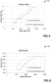
- FIGS. 5 and 6 show example graphical representations of the difference between the advanced angle timing and rail fuel pressure, respectively, during normal operation and port heating using the routine described with respect to FIGS. 3 and 4 .
- the approach described herein may be employed in a variety of engine types and sizes and speeds, and in a variety of engine-driven systems. Some of these systems may be stationary while others may be on semi-mobile or mobile platforms. Semi-mobile platforms may be relocated between operational periods, such as while mounted on flatbed trailers. Mobile platforms include self-propelled vehicles. Such vehicles can include on-road transportation vehicles (e.g., automobiles), mining equipment, marine vessels, rail vehicles, and other off-highway vehicles (OHV). A locomotive is provided as an example of a mobile platform supporting a system incorporating an embodiment of the disclosure.
- a suitable non-vehicle application may include a station power generator.
- FIG. 1 is a block diagram of an example vehicle system having a rail vehicle.
- the vehicle is depicted as locomotive 100 with a main engine housing 102 that can travel on a track 104.
- the locomotive is a diesel electric vehicle operating a diesel engine 106 that is located within the engine housing.
- a suitable engine may consume or utilize various fuels and oils other than diesel fuel and lubricating oil. Suitable other fuels may include gasoline, kerosene, alcohol, natural gas, biodiesel, and mixtures of two or more thereof.
- the engine may include a plurality of cylinders 107.
- engine may include twelve cylinders (two banks of six cylinders each). Further, the plurality of cylinders in the engine may include various sets and subsets of cylinders, such as a first subset of cylinders 109 a and a second subset of cylinders 109 b. In some embodiments, each subset of cylinders may include one or more donor cylinders and one or more non-donor cylinders. In other embodiments, the first subset of cylinders may include only donor cylinders and the second subset of cylinders may include only non-donor cylinders, for example. The various sets and subsets of cylinders may include one or more cylinder groups for selected operating modes, as described herein. In alternate embodiments, alternate engine configurations may be employed, such as a gasoline engine or a biodiesel or natural gas engine, for example.
- a controller 110 may include a computer control system and/or an engine control system.
- the locomotive control system may have computer readable storage media including code for enabling an on-board monitoring and control of locomotive operation.
- the controller may oversee vehicle systems control and management and may receive signals from a variety of sources to estimate vehicle operating parameters.
- the controller may be linked to a display (not shown) to provide a user interface to the vehicle operating crew.
- the controller may be configured to operate with an automatic engine start/stop (AESS) control system on an idle vehicle 100, thereby enabling the vehicle engine to be automatically started and stopped upon fulfillment of AESS criteria as managed by an AESS control routine.
- AESS automatic engine start/stop
- the engine may be started with an engine starting system.
- a generator start may be performed wherein the electrical energy produced by a generator or alternator 116 may be used to start engine.
- the engine starting system may use a motor to start the engine.
- Suitable motors may include an electric starter motor and a compressed air motor.
- the engine may be started using energy from an energy storage device, such as a battery, or other appropriate energy source.
- the diesel engine generates a torque that is transmitted to an alternator 116 along a drive shaft (not shown).
- the generated torque is used by alternator to generate electricity for subsequent propagation of the vehicle.
- the electrical power generated in this manner may be referred to as the prime mover power.
- the electrical power may be transmitted along an electrical bus 117 to a variety of downstream electrical components. Based on the nature of the generated electrical output, the electrical bus may be a direct current (DC) bus (as depicted) or an alternating current (AC) bus.
- DC direct current
- AC alternating current
- Various power electronic components may be used to manage the electrical current.
- the engine may be operated under a plurality of load levels and/or a plurality of engine speeds. These load levels may range from idle on the low end to a peak engine output on the high end.
- Low engine load may include operation at a lower end of the engine load range.
- Mid-engine load may include operation at a mid-level engine load range above low load.
- High engine load may include operation at a higher end of the engine load range, above mid-engine load.
- each cylinder may have a variable cylinder load. These cylinder loads may range from cylinder low-load to cylinder high-load. The engine load and cylinder load may coincide in some instances, while not in other instances.
- the engine overall may be operated under low load, however, some cylinders may be operated at substantially no-load (e.g., deactivated), while other cylinders operate at a mid- to high-load, depending on the number of cylinders operating at the different loads.
- a cylinder fuel injection amount may set a cylinder's load. For example, a cylinder operating without fuel injection may be considered deactivated (in which case it may be referred to as skip fire operation which will be described in greater detail with reference to FIG. 2 ), while a cylinder operating with low fuel injection may be considered to be operating under low-load.
- the alternator may be connected in series to power electronics having one or more rectifiers (not shown) that convert the alternator's electrical output to DC electrical power prior to transmission along the DC bus.
- one or more inverters 118 may be configured to invert the electrical power from the electrical bus prior to supplying electrical power to the downstream component.
- a single inverter may supply AC electrical power from a DC electrical bus to a plurality of components.
- each of a plurality of distinct inverters may supply electrical power to a distinct component.
- the vehicle may include one or more inverters connected to a switch that may be controlled to selectively provide electrical power to different components connected to the switch.
- a traction motor 120 mounted on a truck 122 below the main engine housing, may receive electrical power from alternator via the DC bus to provide traction power to propel the vehicle.
- traction motor may be an AC motor.
- an inverter paired with the traction motor may convert the DC input to an appropriate AC input, such as a three-phase AC input, for subsequent use by the traction motor.
- the traction motor may be a DC motor directly employing the output of the alternator after rectification and transmission along the DC bus.
- One example vehicle configuration may include one inverter/traction motor pair per wheel-axle 124. As depicted herein, six pairs of inverter/traction motors are shown for each of six pairs of wheel-axle of the vehicle. In alternate embodiments, the vehicle may have four inverter/traction motor pairs. In alternative embodiments, a single inverter may be paired with a plurality of traction motors.
- a traction motor 120 may act as a generator providing dynamic braking to brake the vehicle.
- the traction motor may provide torque in a direction that is opposite from the rolling direction thereby generating electricity that is dissipated as heat by a grid of resistors 126 connected to the electrical bus.
- the grid may include stacks of resistive elements connected in series directly to the electrical bus. The stacks of resistive elements may be positioned proximate to the ceiling of main engine housing in order to facilitate air cooling and heat dissipation from the grid.
- air brakes (not shown) making use of compressed air may be used by the vehicle as part of a vehicle braking system. The compressed air may be generated from intake air by a compressor 128.
- a multitude of motor driven airflow devices may be operated for temperature control of vehicle components.
- the airflow devices may include, but are not limited to, blowers, radiators, and fans.
- a variety of blowers (not shown) may be provided for the forced-air cooling of various electrical components. For example, a traction motor blower to cool the traction motor during periods of heavy work, an alternator blower to cool alternator and a grid blower to cool the grid of resistors.
- Each blower may be driven by an AC or DC motor and accordingly may be configured to receive electrical power from DC bus by way of a respective inverter.
- Engine temperature may be maintained in part by a radiator 132.
- Water may be circulated around engine to absorb excess heat and contain the temperature within a desired range for efficient engine operation.
- the heated water may then be passed through radiator 132 wherein air blown through the radiator fan may cool the heated water.
- the radiator fan may be located in a horizontal configuration proximate to the rear ceiling of the vehicle such that upon blade rotation, air may be sucked from below and exhausted.
- a cooling system including a water-based coolant may optionally be used in conjunction with the radiator to provide additional cooling of the engine.
- An on-board electrical energy storage device represented by battery 134 in this example, may be linked to the DC bus.
- a DC-DC converter (not shown) may be disposed between DC bus and battery to allow the high voltage of the DC bus (for example in the range of 1000V) to be stepped down appropriately for use by the battery (for example in the range of 12-75V).
- the on-board electrical energy storage device may be in the form of high voltage batteries, such that the placement of an intermediate DC-DC converter may not be necessitated.
- the battery may be charged by running engine.
- the electrical energy stored in the battery may be used during a stand-by mode of engine operation, or when the engine is shut down, to operate various electronic components such as lights, on-board monitoring systems, microprocessors, processor displays, climate controls, and the like.
- the battery may be used to provide an initial charge to start-up engine from a shut-down condition.
- the electrical energy storage device may be a super-capacitor, for example.
- a lubrication system 140 may include a pressure fed oil system with a crank driven oil pump for lubricating the engine crankshaft, valves, and pistons.
- a reservoir of oil may be stored in a sump below the engine.
- the valves are lubricated with splash oil while the cylinder liners are lubricated by the pressurized oil being fed into the piston, off the crankshaft, for both cooling and lubricating purposes.
- Carry-over of oil into the combustion chamber is controlled by the piston rings.
- the piston rings may be shaped to allow enough oil to reach the top piston ring and lubricate it when the cylinder is working at full load. Gas pressure balance in the piston ring grooves further controls carry-over of oil into the combustion chamber.
- An exhaust stack 142 may receive exhaust gas from the engine and directs it away therefrom. Ducts or tubing (not shown) may be provided between the crankcase (holding the lubricating oil) and the exhaust stack for ventilating the crankcase, for example, for ventilating blow-by gas from the crankcase.
- the lubrication system may supply sufficient oil for a full load operation. However, at light loads, an excess amount of oil may be supplied. Some of the excess oil may be carried into the cylinder chamber and exhaust port. Oil in the combustion chamber may originate from oil retained in the grooves of the cylinder liner walls. As such, the engine may retain some oil in the grooves to provide lubrication for the pistons and rings. Carry-over oil in the combustion chamber may also be contributed by oil lubricating the valves. Herein, oil moves down the valves to provide lubrication between the valve and the valve guide, and further at the seating surface of the valve on the cylinder head.
- the controller communicating with the engine system may enable a port heating routine, as further elaborated in FIGS. 2 and 3 , to allow the unburned oil to be burned off and avert degraded engine performance due to accumulation of unburned oil.
- the routine may also allow unburned fuel, as may have accumulated in the combustion chamber due to poor fuel combustion under low load conditions, to also be burned off.
- an engine may break in after some use, and before being worn out, so as to decrease the risk of souping.
- the controller may reduce or eliminate the port heating routine.
- Various control algorithms may be employed based on, for example, measuring of the actual souping amount at various locations, indirect factors (such as soot production or exhaust opacity), or calculating based on engine age, duty cycle, or megawatt hours produced.
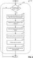
- FIG. 2 depicts a method 200 of determining if a port heating mode of operation may be carried out within a non-EGR engine and/or a high speed internal combustion engine.
- the method may be performed by a control system, or a controller, in communication with an engine to enable exhaust port heating and subsequent burning of unburned oil and/or fuel.
- the control system may operate in at least two modes, with at least one of the modes being a port heating mode, and the controller can change an operating aspect of the port heating mode based at least in part on a calculated or measured level of souping of the engine and/or engine age.
- engine operating conditions may be determined.
- the engine operating conditions may include engine idling condition, idling time, engine load, engine loading time, and the like.
- the engine load is determined. As described above, the engine load may range from idle on the low end to peak engine output on the high end.
- the method may determine if any if conditions have been met for port heating. Conditions that may be met may include when the engine load is below a threshold (e.g., low load), after the engine has experienced conditions that put the engine at risk for oil in the exhaust (e.g., after the engine has been at low load for a duration that may be a relatively extended period of time), when the engine is operating at idle, or during dynamic braking.
- select cylinders may operate with a higher cylinder load (e.g., via the port heating mode) such that exhaust port temperatures are increased so that deposits may be removed.
- the controller may determine one or more of accumulated engine revolutions at low or no load, the load amount, and engine revolutions as a function of MW hrs as at least one factor in determining whether to initiate port heating. For example, speed, engine load, MW hrs, and time may be taken into account so that differential port heating is engaged at multiple speeds (e.g., different speed levels may trigger different levels of port heating). In one embodiment, idle timer criteria may be used to determine if the conditions have been met for port heating.
- the idle timer may be based on different engine speeds (e.g., a first speed, a second speed, a third speed, high speed, medium speed, low speed, etc.) as well as engine age and normalized to an engine revolution count (e.g., by using a two-dimensional (2D) table).
- a normalized engine revolution counter limit may be used as the threshold to enable port heating.
- the counter limit may be expressed as a one-dimensional (ID) vector using engine age in MW hrs versus a normalized engine revolution counter limit.
- step 208 If conditions for port heating have not been met, current engine operation may be continued at step 208. If conditions for port heating have been met, the method may continue at step 210 where the age and souping level of the engine is determined. During idling of diesel engines for extended periods of time, souping may occur where a significant fraction of the engine emissions is not emitted but retained as "soup" (e.g., semi-volatile hydrocarbons and lubricating oil) to be subsequently emitted when the engine returns to higher-load operation. This soup can accumulate and form unwanted deposits downstream of the cylinder exhaust ports.
- port heating may be run on a set of cylinders based on engine age, souping level, and/or the port heating conditions met.
- control system may be configured to operate in at least two modes, with at least one mode being a port heating mode, and the controller further configured to decrease an operating aspect of the port heating mode based on one or more of the frequency of port heating events, the duration of a port heating event, the target temperature of a port heating event, and the amount of fuel used during a port heating event.
- FIG. 3 depicts an example routine 300 by a control system, such as by the controller, in communication with a high-speed diesel engine to enable exhaust port heating and subsequent burning of unburned oil and/or fuel.
- the routine is s operating within a vehicle system for a rail vehicle.
- the operation may consider engine operating conditions, such as an engine idling condition, engine age, engine speed, idling time, engine load, engine loading time, and accordingly initiate a port heating operation.
- the port heating operation may vary dependent on engine age, souping level, and engine speed. In this way, as there is less demand for port heating as the engine breaks in, the fuel consumption penalty associated with port heating may be reduced over time.
- variation in port heating may be decreased based on the frequency and/or duration of port heating events over time and engine use, with differential port heating engaged in response to different thresholds or ratios being met (e.g., different speed, rail pressure or advanced angle ratios/ranges).
- thresholds or ratios e.g., different speed, rail pressure or advanced angle ratios/ranges.
- the port heating operation may include successively operating distinct subsets of cylinders at a cylinder load or fuel injection amount sufficient to increase an exhaust temperature of the subset for burning unburned fuel and/or oil deposited in the subset of cylinders and/or exhaust system, while operating the engine in an overall low-load mode or an idle mode.
- each successively operated subset of cylinders may include at least two cylinders at a time from the same engine bank. Cylinders that are not currently being operated in the subset are operated in a low- or no-fuel mode.
- the successive operation may include first operating a subset of cylinders in the port heating mode, and then operating a different subset of cylinders in the port heating mode, and so on.
- the distinct subsets may have cylinders in common, but each subset is different from the others in terms of at least one cylinder. In this way, it is possible to remove hydrocarbon deposits from the exhaust of all of the cylinders.
- the port heating may include operating the engine in at least two modes, a first mode with a lower fuel injection amount, and a second mode with a higher fuel injection amount.
- the operation may include operating at least two of the cylinders of an engine bank (e.g., the right bank) in the second mode while at least another cylinder of the opposite bank (e.g., the left bank) operates in the first mode to increase exhaust temperature at least of the at least two cylinders in the second mode after a designated amount of low-load engine operation, and during the low-load engine operation.
- an engine bank e.g., the right bank
- the opposite bank e.g., the left bank
- an idle timer is started and an initial setting of time zero is indicated.
- the idle timer may measure an amount of time spent by the engine in idling conditions.
- the idling conditions may include the vehicle parked on a siding for a long term with the engine running at an idling speed.
- the idle timer is incremented based on the time spent in idle mode.
- the idle time may be a continuous idle time without interruptions of other operating modes or may include a plurality of idle conditions which together reach the maximum idle time.
- an engine idling speed may be determined and if the speed is above a determined port heating speed limit, then the port heating operation may be disabled.
- the conditioning procedure may include identifying a first target cylinder where port heating may be initiated and the order of cylinders to follow. Further, the procedure may entail determining injection settings, slew rates, and port heating speeds.
- step 312 it is determined whether the engine is in idle conditions. If the engine is idling, then at step 314, it may be determined whether the port heating procedure has been completed or not. If the port heating procedure has been completed, further port heating may be stopped at step 316 and the idle timer may be reset to zero at step 318. However, if at step 312 it is determined that the engine is not idling, that is, it is determined that the engine is operating at a higher load condition, port heating may be suspended at step 320. The routine may then continue at step 322 to determine if the engine load conditions meets load timer criteria, as further elaborated below.
- unburned oil and/or fuel accumulation may occur during prolonged engine idling conditions.
- the engine exhaust manifold can incur temperature rises that can spontaneously burn off the accumulated unburned oil and/or fuel.
- the port heating procedure may not be necessitated, and accordingly may be suspended.
- the routine may adjust a port heating operation to occur when the engine is idling and thus when the possibility of unburned oil accumulation is higher.
- the routine may accordingly suspend the port heating operation when the engine is running at higher loads and thus when the unburned oil may be burned off during the normal course of the engine's operation. While operation at high load is one example, various operations may trigger suspension of the port heating mode (e.g., an operator throttle request, cold ambient temperatures, engagement of an auxiliary load, etc.).
- step 322 it is determined if the engine has been loaded for a minimum load time. Also, upon suspension of port heating operations of a loaded engine at step 320, the routine may continue to determine whether a minimum load timer duration has been met at step 322. If the engine has been loaded for at least the minimum load time, then further port heating may not be needed in anticipation of exhaust temperature rises sufficient to burn off the accumulated unburned oil and/or fuel. Accordingly, at step 323, port heating may not ensue and the idle timer may be reset to zero.
- step 324 it is determined if the engine is still at idle conditions. If the engine is still idling, the routine may return to step 304 to continue incrementing the idle timer, and thereafter proceed with the port heating operation when the idling time criteria has been met. If the engine is not idling at step 324, then at step 326 the routine may continue incrementing the load timer instead.
- step 328 it is verified whether a port heating operation had been suspended on a previous iteration of the routine. If so, the routine may resume the port heating operation at step 330. If a previous port heating had not been interrupted, then the routine may return to step 322 and continue incrementing the load timer until the minimum load time is reached following which the need for the port heating operation may be negated and consequently the idle timer may be reset to zero.
- two criteria may be considered in the determination of whether or not to proceed with a port heating procedure. These criteria may be a time spent in an idling mode (as may be defined by an idle timer) and an engine load condition (as may be defined by a load timer and/or a loaded or non-idle condition of the engine). It will be appreciated that the accumulation of unburned oil and/or fuel may be a potential issue during idle or low engine load conditions, and further that during operation of the engine in a sufficiently loaded condition of sufficient duration, the temperature of the exhaust manifold may be raised enough to allow the unburned fuel and oil to be burned during the course of loaded-engine operation.
- the engine is in idling conditions and has spent enough time in idling conditions to warrant a port heating operation to avert adverse effects of accumulated unburned oil.
- the idle timer criterion is met, a port heating operation may ensue.
- the idle timer may be reset to allow a new iteration of the operation to follow.
- the engine is not idling, but instead is loaded.
- the engine may have spent enough time in the loaded condition to fulfill the load timer criterion and ensure high exhaust manifold temperatures such that a port heating operation may not be required.
- the idle timer may remain at zero.
- the engine has been idling, but not for long enough to fulfill the idle timer criterion.
- the idling condition of the engine may be interrupted by a sudden operation of the engine in a loaded condition. If the interrupting operation of the engine in the loaded condition continues long enough to fulfill the load timer criterion, then the exhaust manifold temperatures may again be expected to reach desirable high temperatures to allow the unburned oil to be burned off, such that upon returning to idling conditions, a port heating operation may not be required, and as such the idle timer may be reset to zero. However, if the interrupting operation of the engine in the loaded condition is not long enough to fulfill the load timer criterion, then upon completion of the loaded engine operation, the engine may return to an idling condition and resume determination of idle timing.
- the engine has idled long enough to fulfill the idle timer criterion and has proceeded to run a port heating operation.
- the port heating operation may be interrupted by a sudden operation of the engine in a loaded condition. First of all, the idle condition-interrupting running of the engine will cause the port heating operation to be suspended. Next, if the engine is run long enough to fulfill the load timer criterion, then unburned oil and/or fuel may be purged and thus the port heating operation may be aborted and the idle timer may be returned to zero in anticipation of a new iteration.
- a control system may be configured to anticipate accumulation and/or burning of unburned oil in an engine exhaust manifold based on the amount of time spent by the engine in idling conditions vis-a-vis running (or loaded) conditions. Accordingly, by judiciously adjusting the operation of a port heating routine, potential issues related to unburned oil buildup may be averted. Further details of a preconditioning procedure, as well as a running and resumption of a port heating operation, will be elaborated in the context of an example routine 400 of FIG. 4 .
- FIG. 4 depicts an example routine 400 that may be performed by a control system to condition an engine for a subsequent running of (or resumption of) a port heating operation.
- the routine may be performed as part of the conditioning step of the routine described with reference to FIG. 3 at step 308.
- the routine determines an order of cylinders to be purged of their unburned oil buildup.
- the routine allows port heating to be adjusted responsive to engine age, engine speed, and souping level.
- a target set of cylinders is selected from a cylinder bank for initiating the port heating operation. Further, a subsequent order of cylinder purging operation may be determined. For example, based on various engine configurations, the engine may be divided into heating and non-heating ports based on engine banks. In one example, the engine may be a V-12 engine with two banks of six 6 inline cylinders having a log-type exhaust manifold for each bank. The target set of cylinders may be selected from a first bank (e.g., the right bank) with the cylinders in the second bank (e.g., the left bank) including the non-heating ports.
- a first bank e.g., the right bank
- the second bank e.g., the left bank
- the order of port heating may include starting with the target set of cylinders in a designated bank and successively port heating remaining sets of cylinders within the same bank. Further, the cylinder sets may be selected to take advantage of previously heated neighboring cylinders so that the cylinder that may have the greatest accumulation of exhaust hydrocarbons may have the possibility of seeing the longest duration of high temperature exhaust. In some examples, port heating may be operated within an entire bank as opposed to cylinder sets within the bank which may demand the non-heating bank to receive normal fueling.
- port heating settings for the target cylinder set may be determined.
- Port heating settings may be determined based on at least one of engine speed, engine age, souping level, accumulated MW hrs, and idle time.
- the target temperature and duration of port heating may be determined based on current engine demand for established speed, rail pressure (RP), and/or advance angle (AA) ranges or ratios.
- an operating aspect (e.g., duration, temperature, amount of over-fueling, etc.) of the port heating may be further decreased based at least in part on a calculated or measured level of souping of the engine, thereby reducing the associated fuel consumption penalty over time.
- a first set of port heating settings may be determined for high speed engine conditions, a second set of port heating settings determined for medium speed engine conditions, and/or a third set of port heating settings determined for low speed or idle engine conditions.
- high speed engine conditions may include engine speeds ranging from 1,200 to 1,800 rpm, an AA ranging between 17 to 24 degrees, and/or a RP ranging from 800 to 1,000 bar.
- Medium speed engine conditions may include engine speeds ranging 600 to 1,200 rpm, an AA ranging between 5 to 17 degrees, and/or a RP ranging from 600 to 800 bar.
- Low speed engine conditions may include engine speeds ranging below 600 rpm, an AA ranging below 5 degrees, and/or a RP ranging below 600 bar.
- port heating settings may be varied based on different speed, MW hrs, RP, and/or AA ratios (e.g., the temperature or duration of port heating may increase by a specified amount for a specified speed increase relative to the engine age in MW hrs).
- the engine may be controlled to drop to an rpm level below "high speed" as part of the settings for port heating.
- the settings for port heating may not include shifting rpm levels.
- the duration and target temperature of port heating may be decreased at higher speed conditions as compared to that during idling or medium speed conditions.
- port heating may be variable above a high speed threshold based on MW hrs, engine age, and/or a function of time whereas under the high speed threshold port heating may be fixed.
- the temperature, duration, frequency, and/or amount of fuel used by at least one cylinder may be varied during port heating.
- the temperature, duration, frequency, and/or amount of fuel used during port heating may be set at fixed values, the fixed values independent of MW hrs, engine age, and/or a function of time.
- port heating may be run for 18 minutes for every 60 minutes of operation for all speeds under 1,200 rpm whereas the duration of port heating may vary based on time of operation and/or other factors for speeds at or above 1,200 rpm.
- the controller may operate to decrease an operating aspect of the port heating mode based at least in part on a calculated or measured level of souping of the engine.
- the level of engine souping may be calculated by subtracting the emissions during a soup test baseline from those during a soup test, and then dividing by the number of minutes of idle operation between the two tests.
- the calculated amount of souping may be used to adjust a parameter of port heating to increase efficiency/decrease variation of cleaning as well as reduce the fuel consumption penalty associated with port heating over time.
- the temperature and duration of port heating for each threshold may be decreased at lower levels of souping (e.g., as the engine is broken in).
- the port heating event may include over-fueling (e.g., via actuating a fuel injector of at least two cylinders to increase the amount of fuel injected into the cylinders) a set of cylinders within the bank of cylinders where port heating is being operated.
- the amount of over-fueling e.g., the amount of additional fuel injected
- the settings may be communicated to the target cylinder set and at step 408, port heating may be provided in the target cylinder set based on the determined settings.
- the remaining cylinders that is the cylinders not part of the target set selected at step 404 may be set to low cylinder load conditions.
- a status update may be fed back to a controller upon completion of port heating in the target cylinder set.
- the routine may then proceed to the next target cylinder set within the same engine bank in the order determined previously at step 404.
- the controller may determine one or more of an accumulated engine revolutions at low or no load, the load amount, and engine revolutions as a function of MW hrs as at least one factor in determining whether to initiate port heating. For example, speed, engine load, MW hrs, and time may be taken into account so that differential port heating is engaged at multiple speeds (e.g., different speed levels may trigger different levels of port heating).
- idle timer criteria may be used to determine if the conditions have been met for port heating. The idle timer may be based on different engine speeds (e.g., a first speed, a second speed, a third speed, high speed, medium speed, low speed, etc.) as well as engine age and normalized to an engine revolution count.
- a normalized engine revolution counter limit may be used as the threshold to enable port heating.
- the counter limit may be expressed as a one-dimensional (ID) vector (e.g., engine age in MW hrs versus a normalized engine revolution counter limit).
- FIGS. 5 and 6 show non-limiting examples illustrating the AA and RP at different engine speeds, respectively, during port heating using the routines presented in FIGS. 3 and 4 as compared to that during normal engine operation.
- the AA may be decreased during port heating at lower engine speeds (e.g., ranging from 500 to 1,750 rpm) using the routines in FIGS 3 and 4 .
- the RP may be decreased during port heating events at lower engine speeds (e.g., ranging from 500 to 1,500 rpm).
- the RP and AA may be the same as during normal operation.
- the cylinder exhaust ports of an engine may be sequentially and periodically heated to allow unburned oil within to be evaporated and/or combusted. This may reduce or eliminate undesirable buildup of fuel and/or oil in the exhaust ports and exhaust stack.
- exhaust maintenance may be automated and human intervention may be reduced.
Landscapes
- Engineering & Computer Science (AREA)
- Mechanical Engineering (AREA)
- General Engineering & Computer Science (AREA)
- Chemical & Material Sciences (AREA)
- Combustion & Propulsion (AREA)
- Automation & Control Theory (AREA)
- Transportation (AREA)
- Combined Controls Of Internal Combustion Engines (AREA)
- Lubrication Of Internal Combustion Engines (AREA)
- Output Control And Ontrol Of Special Type Engine (AREA)
Abstract
Description
- The present application claims priority to Indian Application No.
202041031788, filed on July 24, 2020 - Embodiments of the subject matter disclosed herein relate to internal combustion engines and, more specifically, to heating cylinder exhaust ports.
- Various engines may have lubrication systems in which pressurized oil can be used to lubricate and/or cool engine valve train components, camshaft assemblies, pistons, and related engine components. Such oil systems may supply sufficient oil for both lubrication and cooling of the engine at full load.
- In some engines, such as large bore engines designed for significant operation under full load, oil from the lubrication system may be retained in the grooves of a cylinder wall and can eventually enter an exhaust system or engine stack. In particular, unburned fuel from combustion during low load conditions can contribute to the accumulation and deposition of unburned fuel and oil in the exhaust system, especially during reduced exhaust port temperatures.
- One approach to address such deposits involves regular exhaust system maintenance. In one example, exhaust stack maintenance may entail service personnel climbing onto the top surface of a locomotive and manually cleaning the exhaust system. However, the need for frequent exhaust system maintenance compounded with the use of complicated manual maneuvers therein may thereby introduce unwanted delays in the operation. Another approach involves, during an exhaust gas recirculation (EGR) cooler heating mode, operating at least one donor cylinder at a cylinder load sufficient to increase an exhaust temperature to a level where local oil and fuel accumulation is burned off. However, this approach demands the use of the EGR system and doesn't account for engine age or engine souping during long idling periods. Thus, there is a fuel consumption penalty associated with this method of port heating. It may be desirable to have a system and method that differs from those that are currently available.
- In one embodiment, a system includes a high speed diesel engine having cylinders in banks, each cylinder having at least one port and a controller that is configured to operate the engine in at least two modes, with at least one mode being a port heating mode. The controller is further configured to vary the port heating mode based on at least one of a function of time, an age of the engine, and a measured or calculated megawatt hours of the engine, so that the variation decreases, for the port heating mode, based on one or more of: a frequency of port heating events, a duration of a port heating event, a target temperature of a port heating event, and an amount of fuel used by at least one of the cylinders during a port heating event.
- In one embodiment, a system includes a high speed diesel engine having cylinders in banks, each cylinder having at least one port, and a controller. The controller configured to operate the engine in at least two modes, with at least one mode being a port heating mode. The controller is further configured to decrease an operating aspect the port heating mode based at least in part on a calculated or measured level of souping of the engine.
-
-
FIG. 1 shows an example embodiment of a diesel-electric locomotive; -
FIG. 2 shows a high level flow chart illustrating a method for an engine, according to an embodiment of the disclosure; -
FIG. 3 shows a high level flowchart illustrating a routine of port heating for a high speed engine, according to an embodiment of the disclosure; -
FIG. 4 shows a high level flowchart for a conditioning routine that may be performed to prepare a high speed engine for an ensuing port heating procedure, according to an embodiment of the disclosure; -
FIG. 5 shows a non-limiting example of graphical data illustrating the timing advance angle during port heating using the routine presented inFIGS. 3 and4 as compared to that during normal engine operation; and -
FIG. 6 shows a non-limiting example of graphical data illustrating rail pressure during port heating using the routine presented inFIGS. 3 and4 as compared to that during normal engine operation. - Engines may have lubrication systems that provide oil for lubricating valve trains, pistons, and other related engine components. Unburned oil and/or fuel may accumulate in an engine exhaust manifold during the course of engine operation. The lubricating system may interact with an engine, controlled by an engine control system, to burn off otherwise unburned oil and/or fuel, and thereby to reduce fouling the engine's exhaust system. One example of such a configuration is illustrated with reference to
FIG. 1 in which a lubricating system interacts with a locomotive engine to provide lubrication during engine operation and an engine controller enables regular exhaust maintenance. - In one embodiment, an engine controller may switch an engine between different operating modes. Examples of operating modes may include normal running mode, low load, high load, high heat mode, startup mode, restricted oxygen mode, and the like. Under normal running conditions, oil used to lubricate the piston can carry-over into the combustion chamber and work its way into the exhaust system. During extended periods of low load operation, exhaust temperatures are not high enough to burn off this oil carry-over. Carry-over, souping and/or excessive soot generation may result in wet oil or soot from within the exhaust system being deposited nearby the engine, such as on the exterior of a vehicle housing the engine and/or back into the air intake system via the EGR (where applicable). In one embodiment, a technical effect may include using port heating to mitigate oil carry-over. Port heating may be accomplished by, for example, over-fueling one or more cylinders to increase exhaust temperatures and locally burn off any oil accumulation before it can travel downstream of the exhaust ports. As further elaborated in
FIGS. 2 ,3 and4 , control routines may be performed to initiate port heating without EGR cooler regeneration where the port heating is graduated out over time and heating is weighted by engine age/souping level, as compared to current methods. In this way, the fuel penalty associated with cylinder port heating may be minimized, taking advantage of the reduction in souping over time as the engine breaks in. - In one embodiment, a system may include a high speed diesel engine having cylinders in banks, each cylinder having at least one port and a controller that can operate the engine in at least two modes, with at least one mode being a port heating mode. The controller may switch to the port heating mode based on one or more triggers. Suitable triggers may include a function of time, an age of the engine, and a measured or calculated megawatt (MW) hours (hrs) of the engine, so that the variation decreases, for the port heating mode, based on one or more of: a frequency of port heating events, a duration of a port heating event, a target temperature of a port heating event, and an amount of fuel used by at least one of the cylinders during a port heating event. A high speed diesel engine may have its highest power output of approximately 5 MW. As non-limiting examples, the high-speed engine may be used to power vehicles, trucks, buses, cars, yachts, shipping vessels, compressors, pumps, and/or generators.
- In another embodiment, a system includes a high speed diesel engine having cylinders in banks, each cylinder having at least one port, and a controller. The controller configured to operate the engine in at least two modes, with at least one mode being a port heating mode. The controller is further configured to decrease an operating aspect the port heating mode based at least in part on a calculated or measured level of souping of the engine.
FIGS. 5 and 6 show example graphical representations of the difference between the advanced angle timing and rail fuel pressure, respectively, during normal operation and port heating using the routine described with respect toFIGS. 3 and4 . - The approach described herein may be employed in a variety of engine types and sizes and speeds, and in a variety of engine-driven systems. Some of these systems may be stationary while others may be on semi-mobile or mobile platforms. Semi-mobile platforms may be relocated between operational periods, such as while mounted on flatbed trailers. Mobile platforms include self-propelled vehicles. Such vehicles can include on-road transportation vehicles (e.g., automobiles), mining equipment, marine vessels, rail vehicles, and other off-highway vehicles (OHV). A locomotive is provided as an example of a mobile platform supporting a system incorporating an embodiment of the disclosure. A suitable non-vehicle application may include a station power generator.
- In one embodiment, a platform is disclosed for an engine disposed in a vehicle.
FIG. 1 is a block diagram of an example vehicle system having a rail vehicle. In the illustrated embodiment, the vehicle is depicted aslocomotive 100 with amain engine housing 102 that can travel on atrack 104. Further, the locomotive is a diesel electric vehicle operating a diesel engine 106 that is located within the engine housing. In alternative embodiments, a suitable engine may consume or utilize various fuels and oils other than diesel fuel and lubricating oil. Suitable other fuels may include gasoline, kerosene, alcohol, natural gas, biodiesel, and mixtures of two or more thereof. The engine may include a plurality ofcylinders 107. In one example, engine may include twelve cylinders (two banks of six cylinders each). Further, the plurality of cylinders in the engine may include various sets and subsets of cylinders, such as a first subset of cylinders 109 a and a second subset of cylinders 109 b. In some embodiments, each subset of cylinders may include one or more donor cylinders and one or more non-donor cylinders. In other embodiments, the first subset of cylinders may include only donor cylinders and the second subset of cylinders may include only non-donor cylinders, for example. The various sets and subsets of cylinders may include one or more cylinder groups for selected operating modes, as described herein. In alternate embodiments, alternate engine configurations may be employed, such as a gasoline engine or a biodiesel or natural gas engine, for example. - An operating crew and electronic components involved in vehicle systems control and management may be housed within a locomotive cab 108. In one example, a controller 110 may include a computer control system and/or an engine control system. The locomotive control system may have computer readable storage media including code for enabling an on-board monitoring and control of locomotive operation. The controller may oversee vehicle systems control and management and may receive signals from a variety of sources to estimate vehicle operating parameters. The controller may be linked to a display (not shown) to provide a user interface to the vehicle operating crew. In one embodiment, the controller may be configured to operate with an automatic engine start/stop (AESS) control system on an
idle vehicle 100, thereby enabling the vehicle engine to be automatically started and stopped upon fulfillment of AESS criteria as managed by an AESS control routine. - The engine may be started with an engine starting system. In one example, a generator start may be performed wherein the electrical energy produced by a generator or
alternator 116 may be used to start engine. Alternatively, the engine starting system may use a motor to start the engine. Suitable motors may include an electric starter motor and a compressed air motor. The engine may be started using energy from an energy storage device, such as a battery, or other appropriate energy source. - The diesel engine generates a torque that is transmitted to an
alternator 116 along a drive shaft (not shown). The generated torque is used by alternator to generate electricity for subsequent propagation of the vehicle. The electrical power generated in this manner may be referred to as the prime mover power. The electrical power may be transmitted along an electrical bus 117 to a variety of downstream electrical components. Based on the nature of the generated electrical output, the electrical bus may be a direct current (DC) bus (as depicted) or an alternating current (AC) bus. Various power electronic components may be used to manage the electrical current. - The engine may be operated under a plurality of load levels and/or a plurality of engine speeds. These load levels may range from idle on the low end to a peak engine output on the high end. Low engine load may include operation at a lower end of the engine load range. Mid-engine load may include operation at a mid-level engine load range above low load. High engine load may include operation at a higher end of the engine load range, above mid-engine load. While the engine may operate at a given engine load, each cylinder may have a variable cylinder load. These cylinder loads may range from cylinder low-load to cylinder high-load. The engine load and cylinder load may coincide in some instances, while not in other instances. For example, the engine overall may be operated under low load, however, some cylinders may be operated at substantially no-load (e.g., deactivated), while other cylinders operate at a mid- to high-load, depending on the number of cylinders operating at the different loads. Further, a cylinder fuel injection amount may set a cylinder's load. For example, a cylinder operating without fuel injection may be considered deactivated (in which case it may be referred to as skip fire operation which will be described in greater detail with reference to
FIG. 2 ), while a cylinder operating with low fuel injection may be considered to be operating under low-load. - The alternator may be connected in series to power electronics having one or more rectifiers (not shown) that convert the alternator's electrical output to DC electrical power prior to transmission along the DC bus. Based on the configuration of a downstream electrical component receiving power from the DC bus, one or
more inverters 118 may be configured to invert the electrical power from the electrical bus prior to supplying electrical power to the downstream component. In one embodiment, a single inverter may supply AC electrical power from a DC electrical bus to a plurality of components. In an alternate embodiment, each of a plurality of distinct inverters may supply electrical power to a distinct component. The vehicle may include one or more inverters connected to a switch that may be controlled to selectively provide electrical power to different components connected to the switch. - A
traction motor 120, mounted on atruck 122 below the main engine housing, may receive electrical power from alternator via the DC bus to provide traction power to propel the vehicle. As described herein, traction motor may be an AC motor. Accordingly, an inverter paired with the traction motor may convert the DC input to an appropriate AC input, such as a three-phase AC input, for subsequent use by the traction motor. In alternate embodiments, the traction motor may be a DC motor directly employing the output of the alternator after rectification and transmission along the DC bus. One example vehicle configuration may include one inverter/traction motor pair per wheel-axle 124. As depicted herein, six pairs of inverter/traction motors are shown for each of six pairs of wheel-axle of the vehicle. In alternate embodiments, the vehicle may have four inverter/traction motor pairs. In alternative embodiments, a single inverter may be paired with a plurality of traction motors. - A
traction motor 120 may act as a generator providing dynamic braking to brake the vehicle. In particular, during dynamic braking, the traction motor may provide torque in a direction that is opposite from the rolling direction thereby generating electricity that is dissipated as heat by a grid ofresistors 126 connected to the electrical bus. In one example, the grid may include stacks of resistive elements connected in series directly to the electrical bus. The stacks of resistive elements may be positioned proximate to the ceiling of main engine housing in order to facilitate air cooling and heat dissipation from the grid. In some embodiments, air brakes (not shown) making use of compressed air may be used by the vehicle as part of a vehicle braking system. The compressed air may be generated from intake air by acompressor 128. - A multitude of motor driven airflow devices may be operated for temperature control of vehicle components. The airflow devices may include, but are not limited to, blowers, radiators, and fans. A variety of blowers (not shown) may be provided for the forced-air cooling of various electrical components. For example, a traction motor blower to cool the traction motor during periods of heavy work, an alternator blower to cool alternator and a grid blower to cool the grid of resistors. Each blower may be driven by an AC or DC motor and accordingly may be configured to receive electrical power from DC bus by way of a respective inverter.
- Engine temperature may be maintained in part by a
radiator 132. Water may be circulated around engine to absorb excess heat and contain the temperature within a desired range for efficient engine operation. The heated water may then be passed throughradiator 132 wherein air blown through the radiator fan may cool the heated water. The radiator fan may be located in a horizontal configuration proximate to the rear ceiling of the vehicle such that upon blade rotation, air may be sucked from below and exhausted. A cooling system including a water-based coolant may optionally be used in conjunction with the radiator to provide additional cooling of the engine. - An on-board electrical energy storage device, represented by
battery 134 in this example, may be linked to the DC bus. A DC-DC converter (not shown) may be disposed between DC bus and battery to allow the high voltage of the DC bus (for example in the range of 1000V) to be stepped down appropriately for use by the battery (for example in the range of 12-75V). In the case of a hybrid vehicle, the on-board electrical energy storage device may be in the form of high voltage batteries, such that the placement of an intermediate DC-DC converter may not be necessitated. The battery may be charged by running engine. The electrical energy stored in the battery may be used during a stand-by mode of engine operation, or when the engine is shut down, to operate various electronic components such as lights, on-board monitoring systems, microprocessors, processor displays, climate controls, and the like. The battery may be used to provide an initial charge to start-up engine from a shut-down condition. In alternate embodiments, the electrical energy storage device may be a super-capacitor, for example. - A
lubrication system 140 may include a pressure fed oil system with a crank driven oil pump for lubricating the engine crankshaft, valves, and pistons. A reservoir of oil may be stored in a sump below the engine. The valves are lubricated with splash oil while the cylinder liners are lubricated by the pressurized oil being fed into the piston, off the crankshaft, for both cooling and lubricating purposes. Carry-over of oil into the combustion chamber is controlled by the piston rings. As such, the piston rings may be shaped to allow enough oil to reach the top piston ring and lubricate it when the cylinder is working at full load. Gas pressure balance in the piston ring grooves further controls carry-over of oil into the combustion chamber. Oil drains out below the oil control ring and as the piston moves up and down the cylinder liner, the oil control ring removes the majority of this oil by scraping. The remaining oil is carried by the remaining piston rings to provide them the needed lubrication. If the oil gets heated during passage around the engine, it may be cooled by passage through the radiator. Anexhaust stack 142 may receive exhaust gas from the engine and directs it away therefrom. Ducts or tubing (not shown) may be provided between the crankcase (holding the lubricating oil) and the exhaust stack for ventilating the crankcase, for example, for ventilating blow-by gas from the crankcase. - The lubrication system may supply sufficient oil for a full load operation. However, at light loads, an excess amount of oil may be supplied. Some of the excess oil may be carried into the cylinder chamber and exhaust port. Oil in the combustion chamber may originate from oil retained in the grooves of the cylinder liner walls. As such, the engine may retain some oil in the grooves to provide lubrication for the pistons and rings. Carry-over oil in the combustion chamber may also be contributed by oil lubricating the valves. Herein, oil moves down the valves to provide lubrication between the valve and the valve guide, and further at the seating surface of the valve on the cylinder head. In some instances, when the engine has accumulated a few hours of operation, the oil carry-over condition may be more severe and the condition may be exacerbated by the carry-over of excess lubrication oil into an associated turbocharger over a period of time. Thus, the controller communicating with the engine system may enable a port heating routine, as further elaborated in
FIGS. 2 and3 , to allow the unburned oil to be burned off and avert degraded engine performance due to accumulation of unburned oil. It will be appreciated that the routine may also allow unburned fuel, as may have accumulated in the combustion chamber due to poor fuel combustion under low load conditions, to also be burned off. Alternatively, an engine may break in after some use, and before being worn out, so as to decrease the risk of souping. In such instances, the controller may reduce or eliminate the port heating routine. Various control algorithms may be employed based on, for example, measuring of the actual souping amount at various locations, indirect factors (such as soot production or exhaust opacity), or calculating based on engine age, duty cycle, or megawatt hours produced. -
FIG. 2 depicts amethod 200 of determining if a port heating mode of operation may be carried out within a non-EGR engine and/or a high speed internal combustion engine. The method may be performed by a control system, or a controller, in communication with an engine to enable exhaust port heating and subsequent burning of unburned oil and/or fuel. The control system may operate in at least two modes, with at least one of the modes being a port heating mode, and the controller can change an operating aspect of the port heating mode based at least in part on a calculated or measured level of souping of the engine and/or engine age. - At
step 202, engine operating conditions may be determined. The engine operating conditions may include engine idling condition, idling time, engine load, engine loading time, and the like. Atstep 204, the engine load is determined. As described above, the engine load may range from idle on the low end to peak engine output on the high end. Atstep 206, the method may determine if any if conditions have been met for port heating. Conditions that may be met may include when the engine load is below a threshold (e.g., low load), after the engine has experienced conditions that put the engine at risk for oil in the exhaust (e.g., after the engine has been at low load for a duration that may be a relatively extended period of time), when the engine is operating at idle, or during dynamic braking. During operation with engine load below the first threshold load, select cylinders may operate with a higher cylinder load (e.g., via the port heating mode) such that exhaust port temperatures are increased so that deposits may be removed. - In another example, the controller may determine one or more of accumulated engine revolutions at low or no load, the load amount, and engine revolutions as a function of MW hrs as at least one factor in determining whether to initiate port heating. For example, speed, engine load, MW hrs, and time may be taken into account so that differential port heating is engaged at multiple speeds (e.g., different speed levels may trigger different levels of port heating). In one embodiment, idle timer criteria may be used to determine if the conditions have been met for port heating. The idle timer may be based on different engine speeds (e.g., a first speed, a second speed, a third speed, high speed, medium speed, low speed, etc.) as well as engine age and normalized to an engine revolution count (e.g., by using a two-dimensional (2D) table). A normalized engine revolution counter limit may be used as the threshold to enable port heating. The counter limit may be expressed as a one-dimensional (ID) vector using engine age in MW hrs versus a normalized engine revolution counter limit.
- If conditions for port heating have not been met, current engine operation may be continued at
step 208. If conditions for port heating have been met, the method may continue atstep 210 where the age and souping level of the engine is determined. During idling of diesel engines for extended periods of time, souping may occur where a significant fraction of the engine emissions is not emitted but retained as "soup" (e.g., semi-volatile hydrocarbons and lubricating oil) to be subsequently emitted when the engine returns to higher-load operation. This soup can accumulate and form unwanted deposits downstream of the cylinder exhaust ports. Atstep 212, port heating may be run on a set of cylinders based on engine age, souping level, and/or the port heating conditions met. In one embodiment, the control system may be configured to operate in at least two modes, with at least one mode being a port heating mode, and the controller further configured to decrease an operating aspect of the port heating mode based on one or more of the frequency of port heating events, the duration of a port heating event, the target temperature of a port heating event, and the amount of fuel used during a port heating event. -
FIG. 3 depicts anexample routine 300 by a control system, such as by the controller, in communication with a high-speed diesel engine to enable exhaust port heating and subsequent burning of unburned oil and/or fuel. As a non-limiting example, the routine is s operating within a vehicle system for a rail vehicle. The operation may consider engine operating conditions, such as an engine idling condition, engine age, engine speed, idling time, engine load, engine loading time, and accordingly initiate a port heating operation. The port heating operation may vary dependent on engine age, souping level, and engine speed. In this way, as there is less demand for port heating as the engine breaks in, the fuel consumption penalty associated with port heating may be reduced over time. For example, variation in port heating may be decreased based on the frequency and/or duration of port heating events over time and engine use, with differential port heating engaged in response to different thresholds or ratios being met (e.g., different speed, rail pressure or advanced angle ratios/ranges). - In one example, the port heating operation may include successively operating distinct subsets of cylinders at a cylinder load or fuel injection amount sufficient to increase an exhaust temperature of the subset for burning unburned fuel and/or oil deposited in the subset of cylinders and/or exhaust system, while operating the engine in an overall low-load mode or an idle mode. During such operation, each successively operated subset of cylinders may include at least two cylinders at a time from the same engine bank. Cylinders that are not currently being operated in the subset are operated in a low- or no-fuel mode. The successive operation may include first operating a subset of cylinders in the port heating mode, and then operating a different subset of cylinders in the port heating mode, and so on. Further, the distinct subsets may have cylinders in common, but each subset is different from the others in terms of at least one cylinder. In this way, it is possible to remove hydrocarbon deposits from the exhaust of all of the cylinders.
- In another example, the port heating may include operating the engine in at least two modes, a first mode with a lower fuel injection amount, and a second mode with a higher fuel injection amount. Specifically, the operation may include operating at least two of the cylinders of an engine bank (e.g., the right bank) in the second mode while at least another cylinder of the opposite bank (e.g., the left bank) operates in the first mode to increase exhaust temperature at least of the at least two cylinders in the second mode after a designated amount of low-load engine operation, and during the low-load engine operation. Thus, even though the overall engine load is low, select cylinders can operate with a high cylinder load to thereby generate sufficient exhaust port temperatures to remove deposits, at least for that cylinder. Then, by changing which cylinders operate in each mode, different cylinders can have their respective exhaust systems cleaned of deposits. Such operation may continue until all cylinders have been operated with port heating, or until the engine load is increased away from idle or low-load operation (e.g., due to traveling conditions of the vehicle). In such cases, if the engine operates at higher load sufficiently, the port heating may be discontinued (e.g., any cylinders that had not yet been operated in the second mode would have been cleaned by the higher load operation, and thus it may be unnecessary to resume the port heating). However, if the load conditions were not sufficiently high, or for too short of a duration, the port heating may resume where it left off.
- Examples of the above operation, along with variations and additional operations are described referring to
FIG. 3 . Atstep 302, an idle timer is started and an initial setting of time zero is indicated. The idle timer may measure an amount of time spent by the engine in idling conditions. In one example, the idling conditions may include the vehicle parked on a siding for a long term with the engine running at an idling speed. Atstep 304, the idle timer is incremented based on the time spent in idle mode. Atstep 306, it is determined whether the time spent in idle mode is greater than a predetermined maximum idle time. In one example, the specified maximum idle time is 6 hours. If yes, then atstep 308, the engine may be conditioned for port heating. Note that the idle time may be a continuous idle time without interruptions of other operating modes or may include a plurality of idle conditions which together reach the maximum idle time. - Also, while the depicted example uses fulfillment of idle timer criteria for enabling port heating, in alternate embodiments, other criteria may be used in addition to the idle timer requirements. As one example, an engine idling speed may be determined and if the speed is above a determined port heating speed limit, then the port heating operation may be disabled. As elaborated further in
FIG. 3 , the conditioning procedure may include identifying a first target cylinder where port heating may be initiated and the order of cylinders to follow. Further, the procedure may entail determining injection settings, slew rates, and port heating speeds. Once the engine has been appropriately conditioned, a port heating operation may be run atstep 310. Alternatively, if the routine is being restarted after a previously interrupted port heating operation, then atstep 310 the operation may be resumed. - Following running of (or resumption of) the port heating procedure, at
step 312, it is determined whether the engine is in idle conditions. If the engine is idling, then atstep 314, it may be determined whether the port heating procedure has been completed or not. If the port heating procedure has been completed, further port heating may be stopped atstep 316 and the idle timer may be reset to zero atstep 318. However, if atstep 312 it is determined that the engine is not idling, that is, it is determined that the engine is operating at a higher load condition, port heating may be suspended atstep 320. The routine may then continue atstep 322 to determine if the engine load conditions meets load timer criteria, as further elaborated below. As such, unburned oil and/or fuel accumulation may occur during prolonged engine idling conditions. However, during engine operation at non-idling conditions, the engine exhaust manifold can incur temperature rises that can spontaneously burn off the accumulated unburned oil and/or fuel. Thus, during engine operation at non-idling conditions, the port heating procedure may not be necessitated, and accordingly may be suspended. In this way, the routine may adjust a port heating operation to occur when the engine is idling and thus when the possibility of unburned oil accumulation is higher. The routine may accordingly suspend the port heating operation when the engine is running at higher loads and thus when the unburned oil may be burned off during the normal course of the engine's operation. While operation at high load is one example, various operations may trigger suspension of the port heating mode (e.g., an operator throttle request, cold ambient temperatures, engagement of an auxiliary load, etc.). - Returning to step 306, if the amount of time spent in idle conditions is not greater than the maximum idle time, then at
step 322, it is determined if the engine has been loaded for a minimum load time. Also, upon suspension of port heating operations of a loaded engine atstep 320, the routine may continue to determine whether a minimum load timer duration has been met atstep 322. If the engine has been loaded for at least the minimum load time, then further port heating may not be needed in anticipation of exhaust temperature rises sufficient to burn off the accumulated unburned oil and/or fuel. Accordingly, atstep 323, port heating may not ensue and the idle timer may be reset to zero. - However, if neither the maximum idling time is met at
step 306, nor the minimum load time is met atstep 322, then atstep 324 it is determined if the engine is still at idle conditions. If the engine is still idling, the routine may return to step 304 to continue incrementing the idle timer, and thereafter proceed with the port heating operation when the idling time criteria has been met. If the engine is not idling atstep 324, then atstep 326 the routine may continue incrementing the load timer instead. Atstep 328, it is verified whether a port heating operation had been suspended on a previous iteration of the routine. If so, the routine may resume the port heating operation atstep 330. If a previous port heating had not been interrupted, then the routine may return to step 322 and continue incrementing the load timer until the minimum load time is reached following which the need for the port heating operation may be negated and consequently the idle timer may be reset to zero. - As such, two criteria may be considered in the determination of whether or not to proceed with a port heating procedure. These criteria may be a time spent in an idling mode (as may be defined by an idle timer) and an engine load condition (as may be defined by a load timer and/or a loaded or non-idle condition of the engine). It will be appreciated that the accumulation of unburned oil and/or fuel may be a potential issue during idle or low engine load conditions, and further that during operation of the engine in a sufficiently loaded condition of sufficient duration, the temperature of the exhaust manifold may be raised enough to allow the unburned fuel and oil to be burned during the course of loaded-engine operation.
- In one example scenario, the engine is in idling conditions and has spent enough time in idling conditions to warrant a port heating operation to avert adverse effects of accumulated unburned oil. In this situation, where the idle timer criterion is met, a port heating operation may ensue. Upon completion of the operation, the idle timer may be reset to allow a new iteration of the operation to follow. In another example, the engine is not idling, but instead is loaded. Herein, the engine may have spent enough time in the loaded condition to fulfill the load timer criterion and ensure high exhaust manifold temperatures such that a port heating operation may not be required. Herein, as long as the engine is operating in non-idle conditions, and the load timer criterion is met, the idle timer may remain at zero.
- In yet another example, the engine has been idling, but not for long enough to fulfill the idle timer criterion. Further, the idling condition of the engine may be interrupted by a sudden operation of the engine in a loaded condition. If the interrupting operation of the engine in the loaded condition continues long enough to fulfill the load timer criterion, then the exhaust manifold temperatures may again be expected to reach desirable high temperatures to allow the unburned oil to be burned off, such that upon returning to idling conditions, a port heating operation may not be required, and as such the idle timer may be reset to zero. However, if the interrupting operation of the engine in the loaded condition is not long enough to fulfill the load timer criterion, then upon completion of the loaded engine operation, the engine may return to an idling condition and resume determination of idle timing.
- In still another example, the engine has idled long enough to fulfill the idle timer criterion and has proceeded to run a port heating operation. However, the port heating operation may be interrupted by a sudden operation of the engine in a loaded condition. First of all, the idle condition-interrupting running of the engine will cause the port heating operation to be suspended. Next, if the engine is run long enough to fulfill the load timer criterion, then unburned oil and/or fuel may be purged and thus the port heating operation may be aborted and the idle timer may be returned to zero in anticipation of a new iteration. However, if the engine is run only for a short amount of time (e.g., not enough to fulfill the load timer criterion) and then returned to idle conditions, the port heating operation may be resumed in anticipation of a need to purge the unburned oil and/or fuel. In this way, a control system may be configured to anticipate accumulation and/or burning of unburned oil in an engine exhaust manifold based on the amount of time spent by the engine in idling conditions vis-a-vis running (or loaded) conditions. Accordingly, by judiciously adjusting the operation of a port heating routine, potential issues related to unburned oil buildup may be averted. Further details of a preconditioning procedure, as well as a running and resumption of a port heating operation, will be elaborated in the context of an
example routine 400 ofFIG. 4 . -
FIG. 4 depicts anexample routine 400 that may be performed by a control system to condition an engine for a subsequent running of (or resumption of) a port heating operation. As such, the routine may be performed as part of the conditioning step of the routine described with reference toFIG. 3 atstep 308. The routine determines an order of cylinders to be purged of their unburned oil buildup. The routine allows port heating to be adjusted responsive to engine age, engine speed, and souping level. Atstep 402, it is determined whether a port heating state machine is in a "RUN" mode (versus a "HOLD" mode). The routine may continue if the run mode has been selected, which in turn requires all the port heating operation criteria to be met. If the state machine is not in the run mode, then the routine may end. - At
step 404, a target set of cylinders is selected from a cylinder bank for initiating the port heating operation. Further, a subsequent order of cylinder purging operation may be determined. For example, based on various engine configurations, the engine may be divided into heating and non-heating ports based on engine banks. In one example, the engine may be a V-12 engine with two banks of six 6 inline cylinders having a log-type exhaust manifold for each bank. The target set of cylinders may be selected from a first bank (e.g., the right bank) with the cylinders in the second bank (e.g., the left bank) including the non-heating ports. In this configuration, the order of port heating may include starting with the target set of cylinders in a designated bank and successively port heating remaining sets of cylinders within the same bank. Further, the cylinder sets may be selected to take advantage of previously heated neighboring cylinders so that the cylinder that may have the greatest accumulation of exhaust hydrocarbons may have the possibility of seeing the longest duration of high temperature exhaust. In some examples, port heating may be operated within an entire bank as opposed to cylinder sets within the bank which may demand the non-heating bank to receive normal fueling. - At
step 406, port heating settings for the target cylinder set may be determined. Port heating settings may be determined based on at least one of engine speed, engine age, souping level, accumulated MW hrs, and idle time. For example, the target temperature and duration of port heating may be determined based on current engine demand for established speed, rail pressure (RP), and/or advance angle (AA) ranges or ratios. Further, an operating aspect (e.g., duration, temperature, amount of over-fueling, etc.) of the port heating may be further decreased based at least in part on a calculated or measured level of souping of the engine, thereby reducing the associated fuel consumption penalty over time. For example, a first set of port heating settings may be determined for high speed engine conditions, a second set of port heating settings determined for medium speed engine conditions, and/or a third set of port heating settings determined for low speed or idle engine conditions. - In one example, high speed engine conditions may include engine speeds ranging from 1,200 to 1,800 rpm, an AA ranging between 17 to 24 degrees, and/or a RP ranging from 800 to 1,000 bar. Medium speed engine conditions may include engine speeds ranging 600 to 1,200 rpm, an AA ranging between 5 to 17 degrees, and/or a RP ranging from 600 to 800 bar. Low speed engine conditions may include engine speeds ranging below 600 rpm, an AA ranging below 5 degrees, and/or a RP ranging below 600 bar. Alternatively, port heating settings may be varied based on different speed, MW hrs, RP, and/or AA ratios (e.g., the temperature or duration of port heating may increase by a specified amount for a specified speed increase relative to the engine age in MW hrs). For example, during high speed engine conditions, the engine may be controlled to drop to an rpm level below "high speed" as part of the settings for port heating. During medium or low speed engine conditions, the settings for port heating may not include shifting rpm levels. The duration and target temperature of port heating may be decreased at higher speed conditions as compared to that during idling or medium speed conditions.
- In one example, port heating may be variable above a high speed threshold based on MW hrs, engine age, and/or a function of time whereas under the high speed threshold port heating may be fixed. For example, above 1,200 rpm the temperature, duration, frequency, and/or amount of fuel used by at least one cylinder may be varied during port heating. For speeds below 1,200 rpm, the temperature, duration, frequency, and/or amount of fuel used during port heating may be set at fixed values, the fixed values independent of MW hrs, engine age, and/or a function of time. In one example, port heating may be run for 18 minutes for every 60 minutes of operation for all speeds under 1,200 rpm whereas the duration of port heating may vary based on time of operation and/or other factors for speeds at or above 1,200 rpm.
- The controller may operate to decrease an operating aspect of the port heating mode based at least in part on a calculated or measured level of souping of the engine. In one example, the level of engine souping may be calculated by subtracting the emissions during a soup test baseline from those during a soup test, and then dividing by the number of minutes of idle operation between the two tests. The calculated amount of souping may be used to adjust a parameter of port heating to increase efficiency/decrease variation of cleaning as well as reduce the fuel consumption penalty associated with port heating over time. For example, the temperature and duration of port heating for each threshold (e.g., speed ranges) may be decreased at lower levels of souping (e.g., as the engine is broken in).
- In one example, the port heating event may include over-fueling (e.g., via actuating a fuel injector of at least two cylinders to increase the amount of fuel injected into the cylinders) a set of cylinders within the bank of cylinders where port heating is being operated. The amount of over-fueling (e.g., the amount of additional fuel injected) may be based on initial port heating settings and further adjusted to account for engine age, souping level, fuel injector health, fuel injector wear, environment (e.g., temperature, altitude, humidity, etc.), time since last engine overhaul and/or the like. Once the settings have been established, they may be communicated to the target cylinder set and at
step 408, port heating may be provided in the target cylinder set based on the determined settings. Atstep 410, the remaining cylinders (that is the cylinders not part of the target set selected at step 404) may be set to low cylinder load conditions. Atstep 412, a status update may be fed back to a controller upon completion of port heating in the target cylinder set. Atstep 414, the routine may then proceed to the next target cylinder set within the same engine bank in the order determined previously atstep 404. - In another example, the controller may determine one or more of an accumulated engine revolutions at low or no load, the load amount, and engine revolutions as a function of MW hrs as at least one factor in determining whether to initiate port heating. For example, speed, engine load, MW hrs, and time may be taken into account so that differential port heating is engaged at multiple speeds (e.g., different speed levels may trigger different levels of port heating). In one embodiment, idle timer criteria may be used to determine if the conditions have been met for port heating. The idle timer may be based on different engine speeds (e.g., a first speed, a second speed, a third speed, high speed, medium speed, low speed, etc.) as well as engine age and normalized to an engine revolution count. A normalized engine revolution counter limit may be used as the threshold to enable port heating. The counter limit may be expressed as a one-dimensional (ID) vector (e.g., engine age in MW hrs versus a normalized engine revolution counter limit).
-
FIGS. 5 and 6 show non-limiting examples illustrating the AA and RP at different engine speeds, respectively, during port heating using the routines presented inFIGS. 3 and4 as compared to that during normal engine operation. As shown in agraph 500 ofFIG. 5 , the AA may be decreased during port heating at lower engine speeds (e.g., ranging from 500 to 1,750 rpm) using the routines inFIGS 3 and4 . Similarly, as shown in agraph 600 ofFIG. 6 , the RP may be decreased during port heating events at lower engine speeds (e.g., ranging from 500 to 1,500 rpm). Alternatively, at higher speed conditions (e.g., above 1,500 rom) the RP and AA may be the same as during normal operation. - The cylinder exhaust ports of an engine may be sequentially and periodically heated to allow unburned oil within to be evaporated and/or combusted. This may reduce or eliminate undesirable buildup of fuel and/or oil in the exhaust ports and exhaust stack. By adjusting the port heating operation responsive to an amount of time spent by the engine in an idling condition and further based on an engine load condition, engine age, and souping level, exhaust maintenance may be automated and human intervention may be reduced.
- As used herein, an element or step recited in the singular and proceeded with the word "a" or "an" should be understood as not excluding plural of said elements or steps, unless such exclusion is explicitly stated. Furthermore, references to "one embodiment" of the invention do not exclude the existence of additional embodiments that also incorporate the recited features. Moreover, unless explicitly stated to the contrary, embodiments "comprising," "including," or "having" an element or a plurality of elements having a particular property may include additional such elements not having that property. The terms "including" and "in which" are used as the plain-language equivalents of the respective terms "comprising" and "wherein." Moreover, the terms "first," "second," and "third," etc. are used merely as labels, and are not intended to impose numerical requirements or a particular positional order on their objects.
- This written description uses examples to disclose the invention, including the best mode, and also to enable a person of ordinary skill in the relevant art to practice the invention, including making and using any devices or systems and performing any incorporated methods. The patentable scope of the invention is defined by the claims, and may include other examples that occur to those of ordinary skill in the art. Such other examples are intended to be within the scope of the claims if they have structural elements that do not differ from the literal language of the claims, or if they include equivalent structural elements with insubstantial differences from the literal languages of the claims.
Claims (9)
- A system, comprising:a high speed diesel engine having cylinders in banks, at least one of the cylinders having at least one port; anda controller that is configured to operate the engine in at least two modes, with at least one mode being a port heating mode, the controller being further configured to change operating aspects of the port heating mode based on at least one of a function of time, an age of the engine, measured or calculated megawatt hours of the engine, a calculated or measured level of souping of the engine, and the engine operating at or above a set high speed threshold so that the operating aspects that are changed comprise, for the port heating mode, a decrease of one or more of:a frequency of port heating events,a duration of a port heating event,a target temperature of the port heating event, andan amount of fuel used by at least one of the cylinders during the port heating event.
- The system of claim 1, wherein at least two cylinders within a first bank operate in the port heating mode and the cylinders within remaining banks of the engine operate in a non-port heating mode.
- The system of claim 2, wherein the controller is further configured to resume the port heating mode by continuing successive operation until all cylinders within the first bank have been operated in the port heating mode at least once.
- The system of any one of the preceding claims, wherein the engine is operating in a locomotive.
- The system of any of the preceding claims, wherein each cylinder has at least one port; and
wherein the controller is further configured to decrease one of the frequency of port heating events, the duration of the port heating event, the target temperature of the port heating event, and the amount of fuel used by at least one of the cylinders during the port heating event based at least in part on the calculated or measured level of souping of the engine. - The system of claim 5, wherein the controller is further configured to decrease at least one of the frequency of port heating events, the duration of the port heating event, the target temperature of the port heating event, and the amount of fuel used by at least one of the cylinders during the port heating event when the engine operates at or above the set high speed threshold.
- The system of claim 6, wherein the at least one of the frequency of port heating events, the duration of the port heating event, the target temperature of the port heating event, and the amount of fuel used by at least one of the cylinders during the port heating event decreased based at least in part on the calculated or measured level of souping of the engine is fixed for speeds below the set high speed threshold.
- The system of claim 6, wherein the set high speed threshold is 1,200 revolutions per minute (rpm).
- A method for a non-exhaust gas recirculation engine and/or a high speed diesel engine with a plurality of cylinders, each cylinder having at least one port, the method comprising:determining operating conditions;determining an engine load;determining if conditions have been met for port heating;continuing current operation if the conditions for port heating have not been met; anddetermining an age and a souping level of the engine if the conditions for port heating have been met and subsequently running port heating on a set of cylinders based on the age of the engine, the souping level of the engine, and/or the conditions met for port heating.
Applications Claiming Priority (1)
| Application Number | Priority Date | Filing Date | Title |
|---|---|---|---|
| IN202041031788 | 2020-07-24 |
Publications (1)
| Publication Number | Publication Date |
|---|---|
| EP3943736A1 true EP3943736A1 (en) | 2022-01-26 |
Family
ID=75562676
Family Applications (1)
| Application Number | Title | Priority Date | Filing Date |
|---|---|---|---|
| EP21168948.4A Pending EP3943736A1 (en) | 2020-07-24 | 2021-04-16 | Port heating system and method |
Country Status (4)
| Country | Link |
|---|---|
| US (1) | US11905903B2 (en) |
| EP (1) | EP3943736A1 (en) |
| CN (1) | CN113969832B (en) |
| EA (1) | EA202092385A1 (en) |
Families Citing this family (2)
| Publication number | Priority date | Publication date | Assignee | Title |
|---|---|---|---|---|
| CN114718723B (en) * | 2022-03-08 | 2023-02-28 | 神龙汽车有限公司 | Method for diagnosing engine oil burning on vehicle |
| CN119091165B (en) * | 2023-10-13 | 2025-10-28 | 四川云感知人工智能科技有限公司 | Sewage purification treatment drug dosage control method and system based on image recognition |
Citations (4)
| Publication number | Priority date | Publication date | Assignee | Title |
|---|---|---|---|---|
| US3295506A (en) * | 1964-07-22 | 1967-01-03 | Canadian Patents Dev | Method and apparatus for the prevention of souping in diesel engines |
| US20100030448A1 (en) * | 2008-07-31 | 2010-02-04 | General Electric Company | Method and system for reducing unburned fuel and oil from exhaust manifolds |
| US20160208744A1 (en) * | 2012-07-12 | 2016-07-21 | General Electric Company | Exhaust gas recirculation system and method |
| JP2018096368A (en) * | 2016-12-08 | 2018-06-21 | 三菱重工業株式会社 | Controller of engine for emergency power generation, engine for emergency power generation and maintenance operation method of engine for emergency power generation |
Family Cites Families (30)
| Publication number | Priority date | Publication date | Assignee | Title |
|---|---|---|---|---|
| JPS57108449A (en) | 1980-12-24 | 1982-07-06 | Toyota Motor Corp | Exhaust gas recirculation system controller for diesel engine |
| SU979672A1 (en) | 1981-06-04 | 1982-12-07 | Ленинградский Ордена Трудового Красного Знамени Сельскохозяйственный Институт | Unit for mounting free decarbonization of i.c. engine injection nozzle sprayers |
| JPS57210155A (en) | 1981-06-16 | 1982-12-23 | Toyota Motor Corp | Exhaust recirculation controller for diesel engine |
| DE10261911A1 (en) * | 2002-12-30 | 2004-07-29 | Volkswagen Ag | Process for controlling the temperature of a catalytic converter and multi-cylinder engine with lambda-split exhaust gas cleaning system |
| US7128052B1 (en) * | 2005-09-09 | 2006-10-31 | Ford Global Technologies, Llc | System and method for exhaust heat generation using electrically actuated cylinder valves |
| US8831858B2 (en) * | 2008-07-31 | 2014-09-09 | General Electric Company | Methods and systems for operating an engine |
| US8903623B2 (en) * | 2009-12-07 | 2014-12-02 | General Electric Company | Method and kit for engine emission control |
| US8903631B2 (en) * | 2011-06-17 | 2014-12-02 | General Electric Company | Methods and systems for exhaust gas recirculation cooler regeneration |
| US8903632B2 (en) * | 2011-06-17 | 2014-12-02 | General Electric Company | Methods and systems for exhaust gas recirculation cooler regeneration |
| GB2492537B (en) | 2011-06-29 | 2014-05-14 | Perkins Engines Co Ltd | Method and apparatus for controlling the operation of a turbocharged internal combustion engine |
| US9109545B2 (en) * | 2011-07-29 | 2015-08-18 | General Electric Company | Systems and methods for controlling exhaust gas recirculation composition |
| DE102011084545B4 (en) * | 2011-10-14 | 2023-03-16 | Ford Global Technologies, Llc | Method for reducing the particle emission of a spark-ignition internal combustion engine with direct injection and an internal combustion engine for carrying out such a method |
| US8857156B2 (en) * | 2012-04-27 | 2014-10-14 | General Electric Company | Engine utilizing a plurality of control valves, and a related method thereof |
| WO2014005127A2 (en) * | 2012-06-28 | 2014-01-03 | Cummins, Inc. | Techniques for controlling a dedicated egr engine |
| US10508621B2 (en) * | 2012-07-12 | 2019-12-17 | Ge Global Sourcing Llc | Exhaust gas recirculation system and method |
| EP3974638B1 (en) * | 2013-09-06 | 2026-01-07 | Cummins, Inc. | Thermal management of exhaust gas via cylinder deactivation |
| US9303581B2 (en) * | 2013-09-18 | 2016-04-05 | Ford Global Technologies, Llc | Systems and methods for injecting gaseous fuel during an exhaust stroke to reduce turbo lag |
| US9074549B1 (en) | 2014-03-24 | 2015-07-07 | Cummins Inc. | Aftertreatment thermal management strategies for internal combustion engines having multiple cylinder banks |
| WO2016029207A1 (en) * | 2014-08-22 | 2016-02-25 | Cummins Inc. | System and method to improve aftertreatment in an internal combustion engine |
| US9951703B2 (en) * | 2014-12-16 | 2018-04-24 | General Electric Company | Systems and method for multi-cylinder misfire detection |
| US10683796B2 (en) * | 2016-03-30 | 2020-06-16 | General Electric Company | Systems and methods for reduced oil carryover |
| JP6601430B2 (en) * | 2017-01-27 | 2019-11-06 | トヨタ自動車株式会社 | Control device for internal combustion engine |
| JP6562011B2 (en) * | 2017-02-14 | 2019-08-21 | トヨタ自動車株式会社 | Fuel injection control device |
| WO2018200623A1 (en) | 2017-04-28 | 2018-11-01 | Cummins Inc. | Methods and systems for removing deposits in an aftertreatment system to minimize visible smoke emissions |
| US11047277B2 (en) * | 2018-05-09 | 2021-06-29 | Transportation Ip Holdings, Llc | Method and systems for particulate matter control |
| WO2020205073A1 (en) | 2019-04-02 | 2020-10-08 | Tula Technology, Inc. | Separately determining firing density and pumping density during firing density transitions for a lean-burn internal combustion engine |
| US11187168B2 (en) * | 2019-09-03 | 2021-11-30 | Ford Global Technologies, Llc | Systems and methods for increasing engine power output under globally stoichiometric operation |
| US11136933B1 (en) * | 2020-04-03 | 2021-10-05 | Ford Global Technologies, Llc | Split lambda fueling operation systems and methods |
| EA202092387A3 (en) * | 2020-07-13 | 2022-03-31 | Пауэрхаус Энджин Солюшнз Свитселанд АйПи Холдинг ГмбХ | INTERNAL COMBUSTION ENGINE SYSTEM |
| US11300063B2 (en) * | 2020-07-20 | 2022-04-12 | Ford Global Technologies, Llc | Systems and methods for split lambda catalyst heating |
-
2020
- 2020-11-03 EA EA202092385A patent/EA202092385A1/en unknown
-
2021
- 2021-01-11 CN CN202110031476.1A patent/CN113969832B/en active Active
- 2021-04-16 EP EP21168948.4A patent/EP3943736A1/en active Pending
- 2021-07-22 US US17/382,695 patent/US11905903B2/en active Active
Patent Citations (4)
| Publication number | Priority date | Publication date | Assignee | Title |
|---|---|---|---|---|
| US3295506A (en) * | 1964-07-22 | 1967-01-03 | Canadian Patents Dev | Method and apparatus for the prevention of souping in diesel engines |
| US20100030448A1 (en) * | 2008-07-31 | 2010-02-04 | General Electric Company | Method and system for reducing unburned fuel and oil from exhaust manifolds |
| US20160208744A1 (en) * | 2012-07-12 | 2016-07-21 | General Electric Company | Exhaust gas recirculation system and method |
| JP2018096368A (en) * | 2016-12-08 | 2018-06-21 | 三菱重工業株式会社 | Controller of engine for emergency power generation, engine for emergency power generation and maintenance operation method of engine for emergency power generation |
Also Published As
| Publication number | Publication date |
|---|---|
| US11905903B2 (en) | 2024-02-20 |
| CN113969832A (en) | 2022-01-25 |
| EA202092385A1 (en) | 2022-01-31 |
| US20220025828A1 (en) | 2022-01-27 |
| CN113969832B (en) | 2024-12-13 |
Similar Documents
| Publication | Publication Date | Title |
|---|---|---|
| US8831858B2 (en) | Methods and systems for operating an engine | |
| US7953541B2 (en) | Method and system for reducing unburned fuel and oil from exhaust manifolds | |
| US20030187553A1 (en) | Control strategy for diesel engine auxiliary loads to reduce emissions during engine power level changes | |
| US6429540B1 (en) | Method and apparatus for controlling engine overspeed due to lube oil ingestion | |
| CN102410100B (en) | Torque limiting engine lubrication protection system | |
| CN112502808B (en) | Method for controlling oil pump of vehicle | |
| US9415766B2 (en) | Regenerative control device of vehicle | |
| US8548715B2 (en) | Method and system for controlling engine performance | |
| WO2010075326A2 (en) | Dual engine locomotive | |
| US11905903B2 (en) | Port heating system and method | |
| WO2011106944A1 (en) | Hybrid drive system and control method thereof | |
| US20080054647A1 (en) | System and Method for Emergency Shutdown of an Internal Combustion Engine | |
| DE10139526A1 (en) | Motor vehicle has gas generator unit that can be switched on when engine is off, drives turbine and thus electric motor as a generator to supply current to vehicle | |
| US11498546B2 (en) | Hybrid vehicle and method of cooling turbocharger | |
| US11142184B2 (en) | Method for operating a hybrid drive apparatus for a motor vehicle as well as a corresponding hybrid drive apparatus | |
| US7315778B1 (en) | System and method for detecting and responding to fugitive fueling of an internal combustion engine | |
| US10662958B2 (en) | Method and systems for a radiator fan | |
| US11973404B2 (en) | Gas engine power generation system | |
| CN112776791B (en) | Method and device for reducing emissions of a hybrid motor vehicle | |
| KR20190092290A (en) | Hybrid vehicle | |
| JP6818376B1 (en) | Gas engine power generation system | |
| EA044585B1 (en) | INTERNAL COMBUSTION ENGINE SYSTEM | |
| CN112922692B (en) | Control method for engine lubricating system used as range extender | |
| Lee et al. | Analysis of the effect of cold start on fuel economy of gasoline automatic transmission vehicle | |
| US10066700B2 (en) | Power transfer assembly |
Legal Events
| Date | Code | Title | Description |
|---|---|---|---|
| PUAI | Public reference made under article 153(3) epc to a published international application that has entered the european phase |
Free format text: ORIGINAL CODE: 0009012 |
|
| STAA | Information on the status of an ep patent application or granted ep patent |
Free format text: STATUS: THE APPLICATION HAS BEEN PUBLISHED |
|
| AK | Designated contracting states |
Kind code of ref document: A1 Designated state(s): AL AT BE BG CH CY CZ DE DK EE ES FI FR GB GR HR HU IE IS IT LI LT LU LV MC MK MT NL NO PL PT RO RS SE SI SK SM TR |
|
| STAA | Information on the status of an ep patent application or granted ep patent |
Free format text: STATUS: REQUEST FOR EXAMINATION WAS MADE |
|
| 17P | Request for examination filed |
Effective date: 20220617 |
|
| P01 | Opt-out of the competence of the unified patent court (upc) registered |
Effective date: 20230530 |
|
| STAA | Information on the status of an ep patent application or granted ep patent |
Free format text: STATUS: EXAMINATION IS IN PROGRESS |
|
| 17Q | First examination report despatched |
Effective date: 20231222 |