EP3943422A1 - A device for singularizing packages arranged one against the other in a row - Google Patents
A device for singularizing packages arranged one against the other in a row Download PDFInfo
- Publication number
- EP3943422A1 EP3943422A1 EP21182706.8A EP21182706A EP3943422A1 EP 3943422 A1 EP3943422 A1 EP 3943422A1 EP 21182706 A EP21182706 A EP 21182706A EP 3943422 A1 EP3943422 A1 EP 3943422A1
- Authority
- EP
- European Patent Office
- Prior art keywords
- drum
- supplying
- packages
- package
- supplying unit
- Prior art date
- Legal status (The legal status is an assumption and is not a legal conclusion. Google has not performed a legal analysis and makes no representation as to the accuracy of the status listed.)
- Granted
Links
Images


Classifications
-
- B—PERFORMING OPERATIONS; TRANSPORTING
- B65—CONVEYING; PACKING; STORING; HANDLING THIN OR FILAMENTARY MATERIAL
- B65G—TRANSPORT OR STORAGE DEVICES, e.g. CONVEYORS FOR LOADING OR TIPPING, SHOP CONVEYOR SYSTEMS OR PNEUMATIC TUBE CONVEYORS
- B65G47/00—Article or material-handling devices associated with conveyors; Methods employing such devices
- B65G47/02—Devices for feeding articles or materials to conveyors
- B65G47/04—Devices for feeding articles or materials to conveyors for feeding articles
- B65G47/06—Devices for feeding articles or materials to conveyors for feeding articles from a single group of articles arranged in orderly pattern, e.g. workpieces in magazines
- B65G47/08—Devices for feeding articles or materials to conveyors for feeding articles from a single group of articles arranged in orderly pattern, e.g. workpieces in magazines spacing or grouping the articles during feeding
-
- B—PERFORMING OPERATIONS; TRANSPORTING
- B65—CONVEYING; PACKING; STORING; HANDLING THIN OR FILAMENTARY MATERIAL
- B65B—MACHINES, APPARATUS OR DEVICES FOR, OR METHODS OF, PACKAGING ARTICLES OR MATERIALS; UNPACKING
- B65B61/00—Auxiliary devices, not otherwise provided for, for operating on sheets, blanks, webs, binding material, containers or packages
- B65B61/04—Auxiliary devices, not otherwise provided for, for operating on sheets, blanks, webs, binding material, containers or packages for severing webs, or for separating joined packages
- B65B61/06—Auxiliary devices, not otherwise provided for, for operating on sheets, blanks, webs, binding material, containers or packages for severing webs, or for separating joined packages by cutting
-
- B—PERFORMING OPERATIONS; TRANSPORTING
- B65—CONVEYING; PACKING; STORING; HANDLING THIN OR FILAMENTARY MATERIAL
- B65B—MACHINES, APPARATUS OR DEVICES FOR, OR METHODS OF, PACKAGING ARTICLES OR MATERIALS; UNPACKING
- B65B35/00—Supplying, feeding, arranging or orientating articles to be packaged
- B65B35/10—Feeding, e.g. conveying, single articles
- B65B35/24—Feeding, e.g. conveying, single articles by endless belts or chains
- B65B35/243—Feeding, e.g. conveying, single articles by endless belts or chains using cooperating conveyors engaging the articles simultaneously
-
- B—PERFORMING OPERATIONS; TRANSPORTING
- B65—CONVEYING; PACKING; STORING; HANDLING THIN OR FILAMENTARY MATERIAL
- B65B—MACHINES, APPARATUS OR DEVICES FOR, OR METHODS OF, PACKAGING ARTICLES OR MATERIALS; UNPACKING
- B65B35/00—Supplying, feeding, arranging or orientating articles to be packaged
- B65B35/10—Feeding, e.g. conveying, single articles
- B65B35/26—Feeding, e.g. conveying, single articles by rotary conveyors
-
- B—PERFORMING OPERATIONS; TRANSPORTING
- B65—CONVEYING; PACKING; STORING; HANDLING THIN OR FILAMENTARY MATERIAL
- B65B—MACHINES, APPARATUS OR DEVICES FOR, OR METHODS OF, PACKAGING ARTICLES OR MATERIALS; UNPACKING
- B65B61/00—Auxiliary devices, not otherwise provided for, for operating on sheets, blanks, webs, binding material, containers or packages
- B65B61/28—Auxiliary devices, not otherwise provided for, for operating on sheets, blanks, webs, binding material, containers or packages for discharging completed packages from machines
-
- B—PERFORMING OPERATIONS; TRANSPORTING
- B65—CONVEYING; PACKING; STORING; HANDLING THIN OR FILAMENTARY MATERIAL
- B65G—TRANSPORT OR STORAGE DEVICES, e.g. CONVEYORS FOR LOADING OR TIPPING, SHOP CONVEYOR SYSTEMS OR PNEUMATIC TUBE CONVEYORS
- B65G47/00—Article or material-handling devices associated with conveyors; Methods employing such devices
- B65G47/02—Devices for feeding articles or materials to conveyors
- B65G47/04—Devices for feeding articles or materials to conveyors for feeding articles
- B65G47/12—Devices for feeding articles or materials to conveyors for feeding articles from disorderly-arranged article piles or from loose assemblages of articles
- B65G47/14—Devices for feeding articles or materials to conveyors for feeding articles from disorderly-arranged article piles or from loose assemblages of articles arranging or orientating the articles by mechanical or pneumatic means during feeding
- B65G47/1407—Devices for feeding articles or materials to conveyors for feeding articles from disorderly-arranged article piles or from loose assemblages of articles arranging or orientating the articles by mechanical or pneumatic means during feeding the articles being fed from a container, e.g. a bowl
- B65G47/1414—Devices for feeding articles or materials to conveyors for feeding articles from disorderly-arranged article piles or from loose assemblages of articles arranging or orientating the articles by mechanical or pneumatic means during feeding the articles being fed from a container, e.g. a bowl by means of movement of at least the whole wall of the container
- B65G47/1428—Devices for feeding articles or materials to conveyors for feeding articles from disorderly-arranged article piles or from loose assemblages of articles arranging or orientating the articles by mechanical or pneumatic means during feeding the articles being fed from a container, e.g. a bowl by means of movement of at least the whole wall of the container rotating movement
-
- B—PERFORMING OPERATIONS; TRANSPORTING
- B65—CONVEYING; PACKING; STORING; HANDLING THIN OR FILAMENTARY MATERIAL
- B65G—TRANSPORT OR STORAGE DEVICES, e.g. CONVEYORS FOR LOADING OR TIPPING, SHOP CONVEYOR SYSTEMS OR PNEUMATIC TUBE CONVEYORS
- B65G47/00—Article or material-handling devices associated with conveyors; Methods employing such devices
- B65G47/02—Devices for feeding articles or materials to conveyors
- B65G47/04—Devices for feeding articles or materials to conveyors for feeding articles
- B65G47/12—Devices for feeding articles or materials to conveyors for feeding articles from disorderly-arranged article piles or from loose assemblages of articles
- B65G47/14—Devices for feeding articles or materials to conveyors for feeding articles from disorderly-arranged article piles or from loose assemblages of articles arranging or orientating the articles by mechanical or pneumatic means during feeding
- B65G47/1492—Devices for feeding articles or materials to conveyors for feeding articles from disorderly-arranged article piles or from loose assemblages of articles arranging or orientating the articles by mechanical or pneumatic means during feeding the articles being fed from a feeding conveyor
Definitions
- the present invention relates to a device for singularizing packages that are reciprocally arranged one against the other according to a linear arrangement, comprising:
- a known device of the indicated type is described, for example, in the Italian patent application ITB020110647 A1 .
- the packages are stacked together inside the first supplying unit and are moved to the delivery position at the singularizing drum along a substantially radial direction.
- the drum is arranged with a plurality of housings, obtained on its side surface, to receive the packages carried by the first supplying unit.
- the package that reaches the delivery position is inserted inside one of the drum housings through a radial movement, and is then moved away and separated from the stack of the other packages by effect of the rotating movement of the drum.
- the packages are subjected to knocks and bounces, which can cause small damages, or rather, defects in the packages, especially due to high operating speeds of the device.
- the present invention aims to provide an improved solution with respect to the prior art discussed, in particular, which is capable of subjecting the packages to more fluid and homogeneous movements.
- the present invention also relates to a method according to claim 8.
- the present invention relates to a device for singularizing packages that are reciprocally arranged one against the other according to a linear arrangement.
- the device described here has been specifically designed for applications in the field of packaging smoking articles, for example, for singularizing packages of smoking articles. In any case, it will be understood that the solution described here can also be used indifferently in other fields, for example, for the packaging of food products, sanitary articles, pharmaceutical products, etc. to name just a few.
- the singularizing device described here indicated as a whole with the reference number 10, comprises:
- the packages P have a parallelepiped shape to simulate packages of smoking articles; in any case, the shape of the packages is - in no way - to be considered as limiting of the application field of the solution described here.
- downstream device 100 may, for example, be a pickup device belonging to a package treatment machine P.
- the first supplying unit 40 is arranged to move the packages P in a row and in contact with each other up to the delivery position K.
- the supplying unit 40 consists of a gravity conveyor designed to move the row of packages P along a predetermined path R, which originates from an inlet section - not illustrated - and ends with an outlet section 42 at the delivery position K ( Figure 2A ).
- the supplying unit 40 consists of a chute formed by two opposing guides 44A, 44B between which the passageway is defined for the packages P along the path R.
- the path R develops starting from an upper region - not illustrated - wherein the aforesaid inlet section is located, according to a descending circular section that ends at the position K defining a supplying direction T.
- the first package P1 of the row therefore, reaches the delivery position K by moving along the direction T.
- the supplying direction T is oriented according to an angle equal to or less than 60° with respect to the supplying direction U of the packages of the second supplying unit 80.
- the direction T is defined by the guide 44A, which, in its terminal section, extends along this direction up to the position K.
- the singularizing drum 20 comprises a plurality of projecting elements 22, distributed in succession along its entire perimeter region, and mutually equidistant. These elements are arranged in such a way that each element and the successive one (with reference to the rotation direction of the drum) operate, respectively, to hold the package P1 with respect to a movement along the supplying direction T, and to push the same package along a direction S that is transverse to the direction T, and in a direction away from the supplying line T and consequently from the axis of rotation I, due to the rotation of the drum.
- the first element 22 functions to hold the package P1 so that its movement is controlled, but without stopping it ( Figure 2A ), while the second projecting element 22 intervenes to divert the package P1 in the transverse direction S towards the supplying unit 80, so as to separate it from the other packages arranged in a row in the supplying unit 40, and leave free the space for approaching a new package P1 to the delivery position K ( Figure 2B ).
- This new package P1 will also be retained by a first element 22 and then diverted by an additional element 22 towards the supplying unit 80.
- each projecting element 22 is delimited by a first surface 22A, and by a second surface 22B, which are parallel to the rotation axis I of the drum, and which define an acute angle ⁇ between each other inside the drum.
- the rotation axis I is not included within the acute angle ⁇ facing the inside of the drum.
- the surface 22A is designed to be arranged substantially parallel to the supplying direction T, in a first angular position of the drum 20 ( Figure 2A ), to carry out the pushing action along the direction S, on a package P1.
- the surface 22B is, instead, designed to be arranged transversely to the supplying direction T, in a second angular position of the drum successive to the first angular position - with reference to the rotation direction of the drum - to hold a subsequent package P1 along the direction T ( Figure 2C ).
- the surface 22B of an element 22, and the surface 22A of the successive element 22 define a seat 24 for receiving the package P1.
- the second supplying unit 80 is positioned below the supplying unit 40 and the singularizing drum 20, and comprises a conveyor belt extending along a closed-loop path and equipped with an upper branch 82 arranged to receive the package P1 separated from the singularizing drum 20, and to supply it to the device 100 located downstream of the singularizing device, along the direction U.
- the conveyor belt is equipped along its surface with a plurality of pusher elements 84, which are preferably constituted by flaps that are transverse to the longitudinal direction of the belt, and which have the function of defining an abutment surface intended to come into contact with the package P1 which is received by the drum 20.
- the supplying unit 80 is arranged to operate in a synchronized manner with the singularizing drum 20, so that for each new package P1 that is separated from the drum 20, a pusher element 84 is ready to immediately bring itself into contact with it, and push it up to the device 100 ( Figure 2C ).
- the supplying unit 80 operates according to an intermittent movement so that each element 84 is stationed near the delivery position K, waiting for the new package P1, and is then immediately advanced to transfer the new package P1 to the device 100.
- the singularizing drum 20 is driven in rotation preferably at a constant speed or - in any case - moderately oscillating in such a way as to generate - in the supplying unit 40 - a flow of packages P that advances continuously and without interruptions.
- the individual packages P1 which - one after the other - reach the delivery position K, are separated from the drum 20 by means of a deviation of their movement, but without being stopped.
- the separate P1 packages are then received, one after the other, by the supplying unit 80, which supplies them, individually, to the downstream device 100.
- the device described here is able to subject the packages to more fluid and homogeneous movements, thus preserving their integrity even for high or very high operating speeds.
Landscapes
- Engineering & Computer Science (AREA)
- Mechanical Engineering (AREA)
- Auxiliary Devices For And Details Of Packaging Control (AREA)
- Making Paper Articles (AREA)
- Measuring Or Testing Involving Enzymes Or Micro-Organisms (AREA)
Abstract
- a singularizing drum (20), which is rotatable about a rotation axis (I), which is preferably horizontal;
- a first supplying unit (40), which is configured to supply packages to a delivery position (K) at the singularizing drum (20);
- a second supplying unit (80), which is configured to receive the packages that have been separated by the singularizing drum (20) and to supply them individually to a device (100) or machine which is set downstream of the singularizing device,
wherein said first supplying unit (40) is configured to move the packages in a line, and in contact with one another, along a movement path (R) terminating at the delivery position (K), according to a given supplying direction (T),
Description
- The present invention relates to a device for singularizing packages that are reciprocally arranged one against the other according to a linear arrangement, comprising:
- a singularizing drum, which is rotatable about a horizontal rotation axis;
- a first supplying unit that is arranged to supply the packages to a delivery position at the singularizing drum; wherein said first supplying unit is arranged to move the packages in a row, and in contact with each other, along a movement path that ends at the delivery position according to a given supplying direction;
- a second supplying unit, which is configured to receive the packages that have been separated by the singularizing drum, and to supply them individually to a device or machine, which is set downstream of the singularizing device,
- A known device of the indicated type is described, for example, in the
Italian patent application ITB020110647 A1 - In this known solution, the packages are stacked together inside the first supplying unit and are moved to the delivery position at the singularizing drum along a substantially radial direction. The drum is arranged with a plurality of housings, obtained on its side surface, to receive the packages carried by the first supplying unit. The package that reaches the delivery position is inserted inside one of the drum housings through a radial movement, and is then moved away and separated from the stack of the other packages by effect of the rotating movement of the drum.
- During the operation of the described singularizing device, the packages are subjected to knocks and bounces, which can cause small damages, or rather, defects in the packages, especially due to high operating speeds of the device.
- The present invention aims to provide an improved solution with respect to the prior art discussed, in particular, which is capable of subjecting the packages to more fluid and homogeneous movements.
- This object is achieved by means of a singularizing device having the characteristics referred to in claim 1.
- The present invention also relates to a method according to claim 8.
- The claims form an integral part of the disclosure provided here.
- Further characteristics and advantages of the present invention will become evident from the description that follows with reference to the attached drawings, provided purely by way of non-limiting example, wherein:
-
Figure 1 represents a preferred embodiment of the singularizing device described here, according to an axonometric view; -
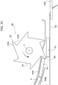
Figures 2 to 2c show an enlarged side view of a region of the device ofFigure 1 , in three different operating conditions of the device, respectively. - In the following description, various specific details are illustrated, aimed at a thorough understanding of the embodiments. The embodiments may be implemented without one or more of the specific details, or with other methods, components, materials, etc. In other cases, known structures, materials or operations are not shown or described in detail to avoid obscuring various aspects of the embodiments.
- The references used here are only for convenience and do not therefore define the field of protection or the scope of the embodiments.
- As anticipated at the beginning, the present invention relates to a device for singularizing packages that are reciprocally arranged one against the other according to a linear arrangement.
- The device described here has been specifically designed for applications in the field of packaging smoking articles, for example, for singularizing packages of smoking articles. In any case, it will be understood that the solution described here can also be used indifferently in other fields, for example, for the packaging of food products, sanitary articles, pharmaceutical products, etc. to name just a few.
- With reference to
Figure 1 , the singularizing device described here, indicated as a whole with thereference number 10, comprises: - a
singularizing drum 20, which is rotatable about a rotation axis I, which is preferably horizontal; - a first supplying
unit 40, which is arranged to supply packages P to a delivery position K at the singularizingdrum 20, and - a second supplying
unit 80, which is arranged to receive the packages P separated from the singularizingdrum 20, and to supply them - individually - to adevice 100 downstream of the singularizing device. According to an alternative embodiment, the axis I of the drum can, for example, be vertical. - In the example shown, the packages P have a parallelepiped shape to simulate packages of smoking articles; in any case, the shape of the packages is - in no way - to be considered as limiting of the application field of the solution described here.
- Furthermore, the
downstream device 100 may, for example, be a pickup device belonging to a package treatment machine P. - Returning to the
device 10, the first supplyingunit 40 is arranged to move the packages P in a row and in contact with each other up to the delivery position K. - In preferred embodiments, such as the one illustrated, the supplying
unit 40 consists of a gravity conveyor designed to move the row of packages P along a predetermined path R, which originates from an inlet section - not illustrated - and ends with an outlet section 42 at the delivery position K (Figure 2A ). - In preferred embodiments, such as the one illustrated, the supplying
unit 40 consists of a chute formed by twoopposing guides - In preferred embodiments, such as the one illustrated, the path R develops starting from an upper region - not illustrated - wherein the aforesaid inlet section is located, according to a descending circular section that ends at the position K defining a supplying direction T.
- The first package P1 of the row, therefore, reaches the delivery position K by moving along the direction T. Preferably, the supplying direction T is oriented according to an angle equal to or less than 60° with respect to the supplying direction U of the packages of the second supplying
unit 80. In the example illustrated, the direction T is defined by theguide 44A, which, in its terminal section, extends along this direction up to the position K. - The singularizing
drum 20 comprises a plurality of projectingelements 22, distributed in succession along its entire perimeter region, and mutually equidistant. These elements are arranged in such a way that each element and the successive one (with reference to the rotation direction of the drum) operate, respectively, to hold the package P1 with respect to a movement along the supplying direction T, and to push the same package along a direction S that is transverse to the direction T, and in a direction away from the supplying line T and consequently from the axis of rotation I, due to the rotation of the drum. - In particular, the
first element 22 functions to hold the package P1 so that its movement is controlled, but without stopping it (Figure 2A ), while the second projectingelement 22 intervenes to divert the package P1 in the transverse direction S towards the supplyingunit 80, so as to separate it from the other packages arranged in a row in the supplyingunit 40, and leave free the space for approaching a new package P1 to the delivery position K (Figure 2B ). This new package P1 will also be retained by afirst element 22 and then diverted by anadditional element 22 towards the supplyingunit 80. - In preferred embodiments, such as the one illustrated, each
projecting element 22 is delimited by afirst surface 22A, and by asecond surface 22B, which are parallel to the rotation axis I of the drum, and which define an acute angle θ between each other inside the drum. Preferably, the rotation axis I is not included within the acute angle θ facing the inside of the drum. In eachprojecting element 22, thesurface 22A is designed to be arranged substantially parallel to the supplying direction T, in a first angular position of the drum 20 (Figure 2A ), to carry out the pushing action along the direction S, on a package P1. On the other hand, thesurface 22B is, instead, designed to be arranged transversely to the supplying direction T, in a second angular position of the drum successive to the first angular position - with reference to the rotation direction of the drum - to hold a subsequent package P1 along the direction T (Figure 2C ). - As can be seen in
Figure 2A , thesurface 22B of anelement 22, and thesurface 22A of the successive element 22 (with reference to the rotation direction of the drum) define aseat 24 for receiving the package P1. - The second supplying
unit 80 is positioned below the supplyingunit 40 and the singularizingdrum 20, and comprises a conveyor belt extending along a closed-loop path and equipped with anupper branch 82 arranged to receive the package P1 separated from the singularizingdrum 20, and to supply it to thedevice 100 located downstream of the singularizing device, along the direction U. - In preferred embodiments, such as the one illustrated, the conveyor belt is equipped along its surface with a plurality of
pusher elements 84, which are preferably constituted by flaps that are transverse to the longitudinal direction of the belt, and which have the function of defining an abutment surface intended to come into contact with the package P1 which is received by thedrum 20. - The supplying
unit 80 is arranged to operate in a synchronized manner with the singularizingdrum 20, so that for each new package P1 that is separated from thedrum 20, apusher element 84 is ready to immediately bring itself into contact with it, and push it up to the device 100 (Figure 2C ). Preferably, the supplyingunit 80 operates according to an intermittent movement so that eachelement 84 is stationed near the delivery position K, waiting for the new package P1, and is then immediately advanced to transfer the new package P1 to thedevice 100. - During operation, the singularizing
drum 20 is driven in rotation preferably at a constant speed or - in any case - moderately oscillating in such a way as to generate - in the supplying unit 40 - a flow of packages P that advances continuously and without interruptions. The individual packages P1 which - one after the other - reach the delivery position K, are separated from thedrum 20 by means of a deviation of their movement, but without being stopped. The separate P1 packages are then received, one after the other, by the supplyingunit 80, which supplies them, individually, to thedownstream device 100. - In view of the above, compared to the prior art discussed at the beginning, the device described here is able to subject the packages to more fluid and homogeneous movements, thus preserving their integrity even for high or very high operating speeds.
- Of course, without prejudice to the principle of the invention, the details of construction and the embodiments may vary, even significantly, with respect to those illustrated here, purely by way of non-limiting example, without departing from the scope of the invention as defined by the attached claims.
Claims (11)
- A device (10) for singularizing packages (P) that are reciprocally arranged one against the other according to a linear arrangement, comprising:- a singularizing drum (20), which is rotatable about a rotation axis (I), which is preferably horizontal;- a first supplying unit (40), which is configured to supply packages to a delivery position (K) at the singularizing drum (20);- a second supplying unit (80), which is configured to receive the packages that have been separated by the singularizing drum (20) and to supply them individually to a device (100) or machine that is set downstream of the singularizing device,wherein said first supplying unit (40) is configured to move the packages in a row and in contact with one another along a movement path (R), terminating at the delivery position (K) according to a given supplying direction (T),
said device being characterized in that
the first supplying unit (40) consists of a gravity conveyor designed to move the row of packages (P) along a predetermined path (R), which originates from an inlet section, and ends with an outlet section (42) at the delivery position (K);
said drum (20) comprises at least one first and one second projecting element (22), which are angularly spaced apart from each other around the rotation axis (I) of the drum, and which are arranged, respectively, to retain the package (P1) with respect to its movement along the supplying direction (T), and to push the package (P1) along a direction (S) transverse to the supplying direction (T) and in a direction away from the rotation axis (I) of the drum, by effect of the rotation of said drum, so as to separate the package from the other packages arranged in a row, and divert it towards the second supplying unit (80); and
the second supplying unit (80) comprises a conveyor belt extending along a closed-loop path, and equipped along its surface with a plurality of pushing elements (84), wherein the second supplying unit (80) is arranged to operate in a synchronized manner with the singularizing drum (20) so that each package that is separated from one of the projecting elements (22) of the drum and that is received on the second supplying unit (80), is pushed by a pusher element (84) of the belt up to the downstream device (100) or machine. - A device according to claim 1, wherein each projecting element (22) is delimited by a first and a second surface (22A, 22B), which are parallel to the rotation axis (I) of the drum, and which define an acute angle between them (θ) that is internal to the drum.
- A device according to claim 1 or 2, wherein the drum (20) comprises a plurality of projecting elements (22) that are distributed in succession along the entire perimetral region of the drum.
- A device according to claims 2 or 3, wherein, in each projecting element, the first surface (22A) is configured to set itself substantially parallel to the supplying direction (T) of the first unit, in a first angular position of the drum, for carrying out the pushing action on the package in the delivery position (K), and
the second surface (22B) is configured to arrange itself transversally to the supplying direction (T) of the first unit (40), in a second angular position of the drum, for holding the package that is approaching to the delivery position (K). - A device according to claim 4, wherein the second surface (22B) of a projecting element (22) and the first surface (22A) of the successive projecting element (22) define a seat (24) that is configured to receive the package that reaches the delivery position (K).
- A device according to any one of the preceding claims, wherein the supplying direction (T) of the first unit (40) is oriented according to an angle equal to or smaller than 60° with respect to a supplying direction (U) of the second supplying unit (80).
- A device according to any one of the preceding claims, wherein the second supplying unit (80) is provided with at least one pusher element (84) for pushing the package (P1), which has been separated, to the downstream device (100) or machine.
- A method for singularizing packages (P) that are reciprocally arranged one against the other according to a linear arrangement, comprising:- by means of a first supplying unit (40), supplying packages to a delivery position (K) at a singularizing drum (20), which is rotatable about a rotation axis (I), this being preferably horizontal;- by means of the singularizing drum (20), separating the package (P1) that reaches the delivery position (K) from the other packages; and- by means of a second supplying unit (80), supplying the separated package to a downstream device (100) or machine;wherein supplying packages to a delivery position (K) includes supplying the packages in a row and in contact with one another along a movement path (R) terminating at the delivery position (K) according to a given supplying direction (T),
the drum (20) comprising at least one first projection element and one second projection element (22), which are angularly spaced apart about the rotation axis (I) of the drum,
said method being characterized in that:said first supplying unit (40) being constituted by a gravity conveyor,the method comprises:through said first supplying unit (40), moving the row of packages (P) along a predetermined path (R), which originates from an inlet section and ends with an outlet section (42) at the delivery position (K);while the drum (20) rotates around its rotation axis (I), holding the package (P1) with respect to its movement along the supplying direction (T), by means of the first projecting element (22) of the drum, and by means of the second projecting element (22), pushing the package (P1) along a direction (S) transverse to the supplying direction (T), and in a direction away from the rotation axis of the drum (I), so as to separate the package (P1) from the other packages (P) arranged in a row, and to divert it towards the second supplying unit (80);the second supplying unit (80) comprising a conveyor belt extending along a closed-loop path, and equipped along its surface with a plurality of pusher elements (84),the method comprising that each package which is separated from one of the projecting elements (22) of the drum and which is received on the second supplying unit (80), is pushed by a pusher element (84) of the belt up to the downstream device (100) or machine. - A method according to claim 8, which includes, during the rotation of the drum (20), by means of the first or the second projecting element (22) of the drum, pushing a first package that reaches the delivery position (K), along a direction that is transverse to the supplying direction (T), and away from the rotation axis (I) of the drum, in a first angular position of the drum (20), and holding a second package with respect to its movement along the supplying direction (T), in a second angular position of the drum, which is successive to the first angular position, with respect to the rotation direction of the drum.
- A method according to claims 8 or 9, wherein the drum (20) rotates at a velocity that is substantially constant, and the packages (P) are supplied to the delivery position (K) by the first supplying unit (40) according to an advancement movement that is at a substantially constant velocity.
- A method according to any one of claims 8 to 10, wherein the second supplying unit operates according to an intermittent movement for transferring, one after another, each single package (P1) that has been separated by the drum (20) to the downstream device (100).
Applications Claiming Priority (1)
| Application Number | Priority Date | Filing Date | Title |
|---|---|---|---|
| IT102020000017557A IT202000017557A1 (en) | 2020-07-20 | 2020-07-20 | SINGULARIZATION DEVICE FOR PACKS ARRANGED IN A ROW |
Publications (2)
| Publication Number | Publication Date |
|---|---|
| EP3943422A1 true EP3943422A1 (en) | 2022-01-26 |
| EP3943422B1 EP3943422B1 (en) | 2023-04-26 |
Family
ID=72801864
Family Applications (1)
| Application Number | Title | Priority Date | Filing Date |
|---|---|---|---|
| EP21182706.8A Active EP3943422B1 (en) | 2020-07-20 | 2021-06-30 | A device for singularizing packages arranged one against the other in a row |
Country Status (4)
| Country | Link |
|---|---|
| EP (1) | EP3943422B1 (en) |
| CN (1) | CN113955241B (en) |
| IT (1) | IT202000017557A1 (en) |
| PL (1) | PL3943422T3 (en) |
Families Citing this family (1)
| Publication number | Priority date | Publication date | Assignee | Title |
|---|---|---|---|---|
| CN117208331B (en) * | 2023-10-26 | 2026-01-30 | 江西华立源锂能科技股份有限公司 | A heat-shrinkable packaging device for lithium battery assembly using heat-shrinkable film. |
Citations (6)
| Publication number | Priority date | Publication date | Assignee | Title |
|---|---|---|---|---|
| DE2103627A1 (en) * | 1970-01-29 | 1971-08-05 | Molins Ltd | Conveyor |
| US4056200A (en) * | 1976-06-24 | 1977-11-01 | Package Machinery Company | High speed stacker |
| US4627215A (en) * | 1984-05-09 | 1986-12-09 | Sig Schweizerische Industrie-Gesellschaft | Apparatus for charging receptacles with stacked, flat items |
| EP0538765A1 (en) * | 1991-10-23 | 1993-04-28 | AZIONARIA COSTRUZIONI MACCHINE AUTOMATICHE-A.C.M.A.-S.p.A. | Method and device for forming groups of flat products, in particular biscuits, for supply to a packing line |
| GB2447779A (en) * | 2007-03-23 | 2008-09-24 | Gd Spa | Group forming apparatus and method |
| ITBO20110647A1 (en) | 2011-11-14 | 2013-05-15 | Gd Spa | PACKAGE RETURN DEVICE IN A PACKAGING LINE. |
Family Cites Families (4)
| Publication number | Priority date | Publication date | Assignee | Title |
|---|---|---|---|---|
| US2570198A (en) * | 1946-04-19 | 1951-10-09 | American Can Co | Container transfer mechanism |
| IT1161654B (en) | 1978-04-18 | 1987-03-18 | Cir Spa Divisione Sasib | DEVICE FOR AUTOMATIC REPLACEMENT OF PACKAGES DISCARDED BY A REGULAR SUPPLY LINE |
| EP3395730A1 (en) | 2017-04-27 | 2018-10-31 | SIG Technology AG | Processing tool and method of processing individual packages |
| EP3501303B1 (en) * | 2017-12-19 | 2020-02-19 | International Tobacco Machinery Poland Sp. z o.o. | Apparatus for manufacturing multi-segment rods of the tobacco processing industry |
-
2020
- 2020-07-20 IT IT102020000017557A patent/IT202000017557A1/en unknown
-
2021
- 2021-06-30 PL PL21182706.8T patent/PL3943422T3/en unknown
- 2021-06-30 EP EP21182706.8A patent/EP3943422B1/en active Active
- 2021-07-20 CN CN202110819979.5A patent/CN113955241B/en active Active
Patent Citations (6)
| Publication number | Priority date | Publication date | Assignee | Title |
|---|---|---|---|---|
| DE2103627A1 (en) * | 1970-01-29 | 1971-08-05 | Molins Ltd | Conveyor |
| US4056200A (en) * | 1976-06-24 | 1977-11-01 | Package Machinery Company | High speed stacker |
| US4627215A (en) * | 1984-05-09 | 1986-12-09 | Sig Schweizerische Industrie-Gesellschaft | Apparatus for charging receptacles with stacked, flat items |
| EP0538765A1 (en) * | 1991-10-23 | 1993-04-28 | AZIONARIA COSTRUZIONI MACCHINE AUTOMATICHE-A.C.M.A.-S.p.A. | Method and device for forming groups of flat products, in particular biscuits, for supply to a packing line |
| GB2447779A (en) * | 2007-03-23 | 2008-09-24 | Gd Spa | Group forming apparatus and method |
| ITBO20110647A1 (en) | 2011-11-14 | 2013-05-15 | Gd Spa | PACKAGE RETURN DEVICE IN A PACKAGING LINE. |
Also Published As
| Publication number | Publication date |
|---|---|
| CN113955241B (en) | 2026-01-13 |
| PL3943422T3 (en) | 2023-06-12 |
| EP3943422B1 (en) | 2023-04-26 |
| IT202000017557A1 (en) | 2022-01-20 |
| CN113955241A (en) | 2022-01-21 |
Similar Documents
| Publication | Publication Date | Title |
|---|---|---|
| US9802721B2 (en) | Machine and method for packing capsules in multi-capsule packs | |
| EP2499069B1 (en) | Unscrambling machine for containers and relative process | |
| US20200324979A1 (en) | Apparatus for unscrambling randomly arranged containers comprising extraction means independent of each other | |
| EP2041006B1 (en) | System and method for turning and separating product packages | |
| US10104898B2 (en) | Apparatus and method for transferring and placing collated sausage links into a packaging item | |
| CN107878819B (en) | item distribution system | |
| EP0814037B1 (en) | Method and device for tip-up conveying packets of cigarettes | |
| US9944471B2 (en) | Device for the treatment of individual sausages | |
| US20040016622A1 (en) | Method and device for supplying regularly objects to a work station | |
| BR112014025531B1 (en) | DEVICE AND METHOD FOR TRANSPORTING GRANULATED PRODUCTS | |
| KR102554915B1 (en) | Device for receiving and conveying a stream of eggs | |
| JP2012136354A (en) | Apparatus and method for transporting food product to loading head | |
| US10820600B2 (en) | Device and method for transferring sausage portions | |
| EP2794398B1 (en) | Method and apparatus for filling and sealing capsules containing loose material | |
| CN107108131B (en) | Apparatus and method for reliably supplying compliant closure elements | |
| US20060240754A1 (en) | Device and method for the ordered deposition of parted sausage portions | |
| EP3943422B1 (en) | A device for singularizing packages arranged one against the other in a row | |
| US9079722B2 (en) | Grouper apparatus for a packaging machine and methods of grouping items for packaging | |
| JP6308887B2 (en) | Accumulator | |
| US12291404B2 (en) | Method and device for feeding articles | |
| WO2020026184A1 (en) | Device for feeding solid food products | |
| EP2543604B1 (en) | Device for forming groups of packages | |
| US20060201780A1 (en) | Continuous motion product transfer system with conveyors | |
| US20040112803A1 (en) | Articles separating and supplying apparatus and method | |
| EP3381843A2 (en) | Device for feeding containers |
Legal Events
| Date | Code | Title | Description |
|---|---|---|---|
| PUAI | Public reference made under article 153(3) epc to a published international application that has entered the european phase |
Free format text: ORIGINAL CODE: 0009012 |
|
| STAA | Information on the status of an ep patent application or granted ep patent |
Free format text: STATUS: THE APPLICATION HAS BEEN PUBLISHED |
|
| AK | Designated contracting states |
Kind code of ref document: A1 Designated state(s): AL AT BE BG CH CY CZ DE DK EE ES FI FR GB GR HR HU IE IS IT LI LT LU LV MC MK MT NL NO PL PT RO RS SE SI SK SM TR |
|
| STAA | Information on the status of an ep patent application or granted ep patent |
Free format text: STATUS: REQUEST FOR EXAMINATION WAS MADE |
|
| 17P | Request for examination filed |
Effective date: 20220329 |
|
| RBV | Designated contracting states (corrected) |
Designated state(s): AL AT BE BG CH CY CZ DE DK EE ES FI FR GB GR HR HU IE IS IT LI LT LU LV MC MK MT NL NO PL PT RO RS SE SI SK SM TR |
|
| RIC1 | Information provided on ipc code assigned before grant |
Ipc: B65G 47/14 20060101ALI20221003BHEP Ipc: B65B 35/26 20060101ALI20221003BHEP Ipc: B65G 47/08 20060101AFI20221003BHEP |
|
| GRAP | Despatch of communication of intention to grant a patent |
Free format text: ORIGINAL CODE: EPIDOSNIGR1 |
|
| STAA | Information on the status of an ep patent application or granted ep patent |
Free format text: STATUS: GRANT OF PATENT IS INTENDED |
|
| INTG | Intention to grant announced |
Effective date: 20230207 |
|
| GRAS | Grant fee paid |
Free format text: ORIGINAL CODE: EPIDOSNIGR3 |
|
| GRAA | (expected) grant |
Free format text: ORIGINAL CODE: 0009210 |
|
| STAA | Information on the status of an ep patent application or granted ep patent |
Free format text: STATUS: THE PATENT HAS BEEN GRANTED |
|
| AK | Designated contracting states |
Kind code of ref document: B1 Designated state(s): AL AT BE BG CH CY CZ DE DK EE ES FI FR GB GR HR HU IE IS IT LI LT LU LV MC MK MT NL NO PL PT RO RS SE SI SK SM TR |
|
| REG | Reference to a national code |
Ref country code: GB Ref legal event code: FG4D |
|
| REG | Reference to a national code |
Ref country code: CH Ref legal event code: EP |
|
| REG | Reference to a national code |
Ref country code: DE Ref legal event code: R096 Ref document number: 602021002044 Country of ref document: DE |
|
| REG | Reference to a national code |
Ref country code: AT Ref legal event code: REF Ref document number: 1562691 Country of ref document: AT Kind code of ref document: T Effective date: 20230515 |
|
| REG | Reference to a national code |
Ref country code: IE Ref legal event code: FG4D |
|
| P01 | Opt-out of the competence of the unified patent court (upc) registered |
Effective date: 20230524 |
|
| REG | Reference to a national code |
Ref country code: LT Ref legal event code: MG9D |
|
| REG | Reference to a national code |
Ref country code: NL Ref legal event code: MP Effective date: 20230426 |
|
| REG | Reference to a national code |
Ref country code: AT Ref legal event code: MK05 Ref document number: 1562691 Country of ref document: AT Kind code of ref document: T Effective date: 20230426 |
|
| PG25 | Lapsed in a contracting state [announced via postgrant information from national office to epo] |
Ref country code: NL Free format text: LAPSE BECAUSE OF FAILURE TO SUBMIT A TRANSLATION OF THE DESCRIPTION OR TO PAY THE FEE WITHIN THE PRESCRIBED TIME-LIMIT Effective date: 20230426 |
|
| PG25 | Lapsed in a contracting state [announced via postgrant information from national office to epo] |
Ref country code: SE Free format text: LAPSE BECAUSE OF FAILURE TO SUBMIT A TRANSLATION OF THE DESCRIPTION OR TO PAY THE FEE WITHIN THE PRESCRIBED TIME-LIMIT Effective date: 20230426 Ref country code: PT Free format text: LAPSE BECAUSE OF FAILURE TO SUBMIT A TRANSLATION OF THE DESCRIPTION OR TO PAY THE FEE WITHIN THE PRESCRIBED TIME-LIMIT Effective date: 20230828 Ref country code: NO Free format text: LAPSE BECAUSE OF FAILURE TO SUBMIT A TRANSLATION OF THE DESCRIPTION OR TO PAY THE FEE WITHIN THE PRESCRIBED TIME-LIMIT Effective date: 20230726 Ref country code: ES Free format text: LAPSE BECAUSE OF FAILURE TO SUBMIT A TRANSLATION OF THE DESCRIPTION OR TO PAY THE FEE WITHIN THE PRESCRIBED TIME-LIMIT Effective date: 20230426 Ref country code: AT Free format text: LAPSE BECAUSE OF FAILURE TO SUBMIT A TRANSLATION OF THE DESCRIPTION OR TO PAY THE FEE WITHIN THE PRESCRIBED TIME-LIMIT Effective date: 20230426 |
|
| PG25 | Lapsed in a contracting state [announced via postgrant information from national office to epo] |
Ref country code: RS Free format text: LAPSE BECAUSE OF FAILURE TO SUBMIT A TRANSLATION OF THE DESCRIPTION OR TO PAY THE FEE WITHIN THE PRESCRIBED TIME-LIMIT Effective date: 20230426 Ref country code: LV Free format text: LAPSE BECAUSE OF FAILURE TO SUBMIT A TRANSLATION OF THE DESCRIPTION OR TO PAY THE FEE WITHIN THE PRESCRIBED TIME-LIMIT Effective date: 20230426 Ref country code: LT Free format text: LAPSE BECAUSE OF FAILURE TO SUBMIT A TRANSLATION OF THE DESCRIPTION OR TO PAY THE FEE WITHIN THE PRESCRIBED TIME-LIMIT Effective date: 20230426 Ref country code: IS Free format text: LAPSE BECAUSE OF FAILURE TO SUBMIT A TRANSLATION OF THE DESCRIPTION OR TO PAY THE FEE WITHIN THE PRESCRIBED TIME-LIMIT Effective date: 20230826 Ref country code: HR Free format text: LAPSE BECAUSE OF FAILURE TO SUBMIT A TRANSLATION OF THE DESCRIPTION OR TO PAY THE FEE WITHIN THE PRESCRIBED TIME-LIMIT Effective date: 20230426 Ref country code: GR Free format text: LAPSE BECAUSE OF FAILURE TO SUBMIT A TRANSLATION OF THE DESCRIPTION OR TO PAY THE FEE WITHIN THE PRESCRIBED TIME-LIMIT Effective date: 20230727 |
|
| PG25 | Lapsed in a contracting state [announced via postgrant information from national office to epo] |
Ref country code: FI Free format text: LAPSE BECAUSE OF FAILURE TO SUBMIT A TRANSLATION OF THE DESCRIPTION OR TO PAY THE FEE WITHIN THE PRESCRIBED TIME-LIMIT Effective date: 20230426 |
|
| PG25 | Lapsed in a contracting state [announced via postgrant information from national office to epo] |
Ref country code: SK Free format text: LAPSE BECAUSE OF FAILURE TO SUBMIT A TRANSLATION OF THE DESCRIPTION OR TO PAY THE FEE WITHIN THE PRESCRIBED TIME-LIMIT Effective date: 20230426 |
|
| PG25 | Lapsed in a contracting state [announced via postgrant information from national office to epo] |
Ref country code: MC Free format text: LAPSE BECAUSE OF FAILURE TO SUBMIT A TRANSLATION OF THE DESCRIPTION OR TO PAY THE FEE WITHIN THE PRESCRIBED TIME-LIMIT Effective date: 20230426 |
|
| REG | Reference to a national code |
Ref country code: DE Ref legal event code: R026 Ref document number: 602021002044 Country of ref document: DE |
|
| PG25 | Lapsed in a contracting state [announced via postgrant information from national office to epo] |
Ref country code: SM Free format text: LAPSE BECAUSE OF FAILURE TO SUBMIT A TRANSLATION OF THE DESCRIPTION OR TO PAY THE FEE WITHIN THE PRESCRIBED TIME-LIMIT Effective date: 20230426 Ref country code: SK Free format text: LAPSE BECAUSE OF FAILURE TO SUBMIT A TRANSLATION OF THE DESCRIPTION OR TO PAY THE FEE WITHIN THE PRESCRIBED TIME-LIMIT Effective date: 20230426 Ref country code: RO Free format text: LAPSE BECAUSE OF FAILURE TO SUBMIT A TRANSLATION OF THE DESCRIPTION OR TO PAY THE FEE WITHIN THE PRESCRIBED TIME-LIMIT Effective date: 20230426 Ref country code: MC Free format text: LAPSE BECAUSE OF FAILURE TO SUBMIT A TRANSLATION OF THE DESCRIPTION OR TO PAY THE FEE WITHIN THE PRESCRIBED TIME-LIMIT Effective date: 20230426 Ref country code: EE Free format text: LAPSE BECAUSE OF FAILURE TO SUBMIT A TRANSLATION OF THE DESCRIPTION OR TO PAY THE FEE WITHIN THE PRESCRIBED TIME-LIMIT Effective date: 20230426 Ref country code: DK Free format text: LAPSE BECAUSE OF FAILURE TO SUBMIT A TRANSLATION OF THE DESCRIPTION OR TO PAY THE FEE WITHIN THE PRESCRIBED TIME-LIMIT Effective date: 20230426 Ref country code: CZ Free format text: LAPSE BECAUSE OF FAILURE TO SUBMIT A TRANSLATION OF THE DESCRIPTION OR TO PAY THE FEE WITHIN THE PRESCRIBED TIME-LIMIT Effective date: 20230426 |
|
| PLBI | Opposition filed |
Free format text: ORIGINAL CODE: 0009260 |
|
| PLAX | Notice of opposition and request to file observation + time limit sent |
Free format text: ORIGINAL CODE: EPIDOSNOBS2 |
|
| REG | Reference to a national code |
Ref country code: BE Ref legal event code: MM Effective date: 20230630 |
|
| PG25 | Lapsed in a contracting state [announced via postgrant information from national office to epo] |
Ref country code: LU Free format text: LAPSE BECAUSE OF NON-PAYMENT OF DUE FEES Effective date: 20230630 |
|
| 26 | Opposition filed |
Opponent name: FOCKE & CO. (GMBH & CO. KG) Effective date: 20240126 |
|
| REG | Reference to a national code |
Ref country code: IE Ref legal event code: MM4A |
|
| PG25 | Lapsed in a contracting state [announced via postgrant information from national office to epo] |
Ref country code: LU Free format text: LAPSE BECAUSE OF NON-PAYMENT OF DUE FEES Effective date: 20230630 |
|
| PG25 | Lapsed in a contracting state [announced via postgrant information from national office to epo] |
Ref country code: IE Free format text: LAPSE BECAUSE OF NON-PAYMENT OF DUE FEES Effective date: 20230630 |
|
| PG25 | Lapsed in a contracting state [announced via postgrant information from national office to epo] |
Ref country code: IE Free format text: LAPSE BECAUSE OF NON-PAYMENT OF DUE FEES Effective date: 20230630 |
|
| PG25 | Lapsed in a contracting state [announced via postgrant information from national office to epo] |
Ref country code: SI Free format text: LAPSE BECAUSE OF FAILURE TO SUBMIT A TRANSLATION OF THE DESCRIPTION OR TO PAY THE FEE WITHIN THE PRESCRIBED TIME-LIMIT Effective date: 20230426 |
|
| PG25 | Lapsed in a contracting state [announced via postgrant information from national office to epo] |
Ref country code: SI Free format text: LAPSE BECAUSE OF FAILURE TO SUBMIT A TRANSLATION OF THE DESCRIPTION OR TO PAY THE FEE WITHIN THE PRESCRIBED TIME-LIMIT Effective date: 20230426 Ref country code: IT Free format text: LAPSE BECAUSE OF FAILURE TO SUBMIT A TRANSLATION OF THE DESCRIPTION OR TO PAY THE FEE WITHIN THE PRESCRIBED TIME-LIMIT Effective date: 20230426 Ref country code: FR Free format text: LAPSE BECAUSE OF NON-PAYMENT OF DUE FEES Effective date: 20230630 Ref country code: BE Free format text: LAPSE BECAUSE OF NON-PAYMENT OF DUE FEES Effective date: 20230630 |
|
| PLBB | Reply of patent proprietor to notice(s) of opposition received |
Free format text: ORIGINAL CODE: EPIDOSNOBS3 |
|
| PLAB | Opposition data, opponent's data or that of the opponent's representative modified |
Free format text: ORIGINAL CODE: 0009299OPPO |
|
| R26 | Opposition filed (corrected) |
Opponent name: FOCKE & CO. (GMBH & CO. KG) Effective date: 20240126 |
|
| PG25 | Lapsed in a contracting state [announced via postgrant information from national office to epo] |
Ref country code: BG Free format text: LAPSE BECAUSE OF FAILURE TO SUBMIT A TRANSLATION OF THE DESCRIPTION OR TO PAY THE FEE WITHIN THE PRESCRIBED TIME-LIMIT Effective date: 20230426 |
|
| PG25 | Lapsed in a contracting state [announced via postgrant information from national office to epo] |
Ref country code: BG Free format text: LAPSE BECAUSE OF FAILURE TO SUBMIT A TRANSLATION OF THE DESCRIPTION OR TO PAY THE FEE WITHIN THE PRESCRIBED TIME-LIMIT Effective date: 20230426 |
|
| REG | Reference to a national code |
Ref country code: CH Ref legal event code: PL |
|
| REG | Reference to a national code |
Ref country code: DE Ref legal event code: R100 Ref document number: 602021002044 Country of ref document: DE |
|
| PG25 | Lapsed in a contracting state [announced via postgrant information from national office to epo] |
Ref country code: CH Free format text: LAPSE BECAUSE OF NON-PAYMENT OF DUE FEES Effective date: 20240630 |
|
| PLCK | Communication despatched that opposition was rejected |
Free format text: ORIGINAL CODE: EPIDOSNREJ1 |
|
| PG25 | Lapsed in a contracting state [announced via postgrant information from national office to epo] |
Ref country code: CY Free format text: LAPSE BECAUSE OF FAILURE TO SUBMIT A TRANSLATION OF THE DESCRIPTION OR TO PAY THE FEE WITHIN THE PRESCRIBED TIME-LIMIT; INVALID AB INITIO Effective date: 20210630 |
|
| PLBN | Opposition rejected |
Free format text: ORIGINAL CODE: 0009273 |
|
| STAA | Information on the status of an ep patent application or granted ep patent |
Free format text: STATUS: OPPOSITION REJECTED |
|
| PG25 | Lapsed in a contracting state [announced via postgrant information from national office to epo] |
Ref country code: HU Free format text: LAPSE BECAUSE OF FAILURE TO SUBMIT A TRANSLATION OF THE DESCRIPTION OR TO PAY THE FEE WITHIN THE PRESCRIBED TIME-LIMIT; INVALID AB INITIO Effective date: 20210630 |
|
| 27O | Opposition rejected |
Effective date: 20250408 |
|
| PG25 | Lapsed in a contracting state [announced via postgrant information from national office to epo] |
Ref country code: TR Free format text: LAPSE BECAUSE OF FAILURE TO SUBMIT A TRANSLATION OF THE DESCRIPTION OR TO PAY THE FEE WITHIN THE PRESCRIBED TIME-LIMIT Effective date: 20230426 |
|
| GBPC | Gb: european patent ceased through non-payment of renewal fee |
Effective date: 20250630 |
|
| PG25 | Lapsed in a contracting state [announced via postgrant information from national office to epo] |
Ref country code: GB Free format text: LAPSE BECAUSE OF NON-PAYMENT OF DUE FEES Effective date: 20250630 |
|
| PG25 | Lapsed in a contracting state [announced via postgrant information from national office to epo] |
Ref country code: CH Free format text: THE PATENT HAS BEEN ANNULLED BY A DECISION OF A NATIONAL AUTHORITY Effective date: 20240630 |
|
| PGFP | Annual fee paid to national office [announced via postgrant information from national office to epo] |
Ref country code: PL Payment date: 20260608 Year of fee payment: 6 |
|
| PGFP | Annual fee paid to national office [announced via postgrant information from national office to epo] |
Ref country code: DE Payment date: 20260629 Year of fee payment: 6 |
|
| PG25 | Lapsed in a contracting state [announced via postgrant information from national office to epo] |
Ref country code: MT Free format text: LAPSE BECAUSE OF NON-PAYMENT OF DUE FEES Effective date: 20230630 |