EP3943394A1 - Air distribution system for use in an aircraft - Google Patents
Air distribution system for use in an aircraft Download PDFInfo
- Publication number
- EP3943394A1 EP3943394A1 EP21185438.5A EP21185438A EP3943394A1 EP 3943394 A1 EP3943394 A1 EP 3943394A1 EP 21185438 A EP21185438 A EP 21185438A EP 3943394 A1 EP3943394 A1 EP 3943394A1
- Authority
- EP
- European Patent Office
- Prior art keywords
- aircraft
- air
- interior
- accordance
- zone
- Prior art date
- Legal status (The legal status is an assumption and is not a legal conclusion. Google has not performed a legal analysis and makes no representation as to the accuracy of the status listed.)
- Granted
Links
Images



Classifications
-
- B—PERFORMING OPERATIONS; TRANSPORTING
- B64—AIRCRAFT; AVIATION; COSMONAUTICS
- B64D—EQUIPMENT FOR FITTING IN OR TO AIRCRAFT; FLIGHT SUITS; PARACHUTES; ARRANGEMENT OR MOUNTING OF POWER PLANTS OR PROPULSION TRANSMISSIONS IN AIRCRAFT
- B64D13/00—Arrangements or adaptations of air-treatment apparatus for aircraft crew or passengers, or freight space
-
- B—PERFORMING OPERATIONS; TRANSPORTING
- B64—AIRCRAFT; AVIATION; COSMONAUTICS
- B64D—EQUIPMENT FOR FITTING IN OR TO AIRCRAFT; FLIGHT SUITS; PARACHUTES; ARRANGEMENT OR MOUNTING OF POWER PLANTS OR PROPULSION TRANSMISSIONS IN AIRCRAFT
- B64D13/00—Arrangements or adaptations of air-treatment apparatus for aircraft crew or passengers, or freight space
- B64D13/02—Arrangements or adaptations of air-treatment apparatus for aircraft crew or passengers, or freight space the air being pressurised
-
- B—PERFORMING OPERATIONS; TRANSPORTING
- B64—AIRCRAFT; AVIATION; COSMONAUTICS
- B64D—EQUIPMENT FOR FITTING IN OR TO AIRCRAFT; FLIGHT SUITS; PARACHUTES; ARRANGEMENT OR MOUNTING OF POWER PLANTS OR PROPULSION TRANSMISSIONS IN AIRCRAFT
- B64D13/00—Arrangements or adaptations of air-treatment apparatus for aircraft crew or passengers, or freight space
- B64D13/06—Arrangements or adaptations of air-treatment apparatus for aircraft crew or passengers, or freight space the air being conditioned
-
- B—PERFORMING OPERATIONS; TRANSPORTING
- B64—AIRCRAFT; AVIATION; COSMONAUTICS
- B64D—EQUIPMENT FOR FITTING IN OR TO AIRCRAFT; FLIGHT SUITS; PARACHUTES; ARRANGEMENT OR MOUNTING OF POWER PLANTS OR PROPULSION TRANSMISSIONS IN AIRCRAFT
- B64D11/00—Passenger or crew accommodation; Flight-deck installations not otherwise provided for
- B64D11/003—Stowage devices for passengers' personal luggage
-
- B—PERFORMING OPERATIONS; TRANSPORTING
- B64—AIRCRAFT; AVIATION; COSMONAUTICS
- B64D—EQUIPMENT FOR FITTING IN OR TO AIRCRAFT; FLIGHT SUITS; PARACHUTES; ARRANGEMENT OR MOUNTING OF POWER PLANTS OR PROPULSION TRANSMISSIONS IN AIRCRAFT
- B64D13/00—Arrangements or adaptations of air-treatment apparatus for aircraft crew or passengers, or freight space
- B64D2013/003—Cabin ventilation nozzles
-
- B—PERFORMING OPERATIONS; TRANSPORTING
- B64—AIRCRAFT; AVIATION; COSMONAUTICS
- B64D—EQUIPMENT FOR FITTING IN OR TO AIRCRAFT; FLIGHT SUITS; PARACHUTES; ARRANGEMENT OR MOUNTING OF POWER PLANTS OR PROPULSION TRANSMISSIONS IN AIRCRAFT
- B64D13/00—Arrangements or adaptations of air-treatment apparatus for aircraft crew or passengers, or freight space
- B64D13/06—Arrangements or adaptations of air-treatment apparatus for aircraft crew or passengers, or freight space the air being conditioned
- B64D2013/0603—Environmental Control Systems
-
- B—PERFORMING OPERATIONS; TRANSPORTING
- B64—AIRCRAFT; AVIATION; COSMONAUTICS
- B64D—EQUIPMENT FOR FITTING IN OR TO AIRCRAFT; FLIGHT SUITS; PARACHUTES; ARRANGEMENT OR MOUNTING OF POWER PLANTS OR PROPULSION TRANSMISSIONS IN AIRCRAFT
- B64D13/00—Arrangements or adaptations of air-treatment apparatus for aircraft crew or passengers, or freight space
- B64D13/06—Arrangements or adaptations of air-treatment apparatus for aircraft crew or passengers, or freight space the air being conditioned
- B64D2013/0603—Environmental Control Systems
- B64D2013/0625—Environmental Control Systems comprising means for distribution effusion of conditioned air in the cabin
-
- B—PERFORMING OPERATIONS; TRANSPORTING
- B64—AIRCRAFT; AVIATION; COSMONAUTICS
- B64D—EQUIPMENT FOR FITTING IN OR TO AIRCRAFT; FLIGHT SUITS; PARACHUTES; ARRANGEMENT OR MOUNTING OF POWER PLANTS OR PROPULSION TRANSMISSIONS IN AIRCRAFT
- B64D13/00—Arrangements or adaptations of air-treatment apparatus for aircraft crew or passengers, or freight space
- B64D13/06—Arrangements or adaptations of air-treatment apparatus for aircraft crew or passengers, or freight space the air being conditioned
- B64D2013/0603—Environmental Control Systems
- B64D2013/0651—Environmental Control Systems comprising filters, e.g. dust filters
Definitions
- the field relates generally to environmental control systems for use in confined spaces designed for human occupancy and, more specifically, to air distribution systems that facilitate minimizing airflow between passengers within confined spaces, such as aircraft passenger cabins.
- ECS Environmental Control Systems
- the ECS generally channels external air from the engines towards the aircraft cabin to pressurize the cabin.
- Some known systems condition the air using air conditioning packs, and the conditioned air is distributed within the cabin via an air distribution system.
- Some air distribution systems include multiple discrete nozzles located on either side of the interior of the aircraft fuselage above the passengers. The nozzles discharge conditioned air therefrom to generate two opposing and counter-rotating "cells" of air that circulate across the passenger seats before exiting the cabin through a return air grille located at the floor of the cabin.
- generating the counter-rotating cells requires the air to be discharged at relatively high velocities, which can generate undesirable noise pollution within the cabin.
- the counter-rotating cells may cause cross-circulation to occur between passengers, which is a significant consideration in view of recent global health crises.
- One aspect is an aircraft including a side wall at least partially defining a passenger cabin and a crown section of the aircraft.
- the passenger cabin includes an overhead zone, a passenger zone, and a floor zone.
- An air supply duct is positioned within the crown section, and the air supply duct is configured to pressurize the crown section with air.
- At least one return air outlet is defined in the floor zone.
- An interior structure is coupled to the side wall and extends between the passenger cabin and the crown section.
- the interior structure includes a plurality of nozzles oriented to discharge the pressurized air from the crown section along an airflow path that extends downward through the overhead zone, downward through the passenger zone, and then towards the at least one return air outlet.
- Another aspect is an aircraft including a side wall at least partially defining a passenger cabin and a crown section of the aircraft.
- the passenger cabin includes an overhead zone, a passenger zone, and a floor zone.
- An air supply duct is positioned within the crown section, and the air supply duct is configured to channel air therethrough.
- At least one return air outlet is defined in the floor zone.
- a plurality of interior panels extend between the passenger cabin and the crown section, and each interior panel is coupled in flow communication with the air supply duct.
- the plurality of interior panels each include a plurality of perforations configured to discharge the air therefrom along an airflow path that extends downward through the overhead zone, downward through the passenger zone, and then towards the at least one return air outlet.
- an air distribution system including an air supply duct configured to channel air therethrough.
- a plurality of interior panels are each coupled in flow communication with the air supply duct, and the plurality of interior panels are coupled to each other in an array to define an interior structure.
- Each interior panel includes a housing having a side wall defining an air inlet and an air outlet.
- a porous support structure is coupled to the side wall at the air outlet.
- An air plenum is defined between the air inlet and a first side of the porous support structure, and a plurality of perforations configured to discharge the air therefrom are defined on a second side of the porous support structure.
- Example systems described below include air distribution systems that facilitate minimizing airflow between passengers within confined spaces, such as aircraft passenger cabins.
- Example systems described provide a displacement ventilation scheme that generates bulk downward airflow within the confined space.
- the bulk downward airflow is discharged from above seated passengers in the confined space, downward past the passengers, and towards an outlet located at the floor of the confined space.
- This directional bulk downward airflow facilitates limiting cross-circulation between passengers seated next to each other in a respective row of an aircraft, for example.
- Example systems facilitate reducing the spread of airborne contaminants between nearby occupants, reducing noise and undesirable drafts, and limiting the formation of stagnant zones of circulation within the confined space.
- FIG. 1 is a cross-sectional view of an aircraft 100 having an example air distribution system 102 therein.
- Aircraft 100 includes a fuselage 104 having a side wall 106 that at least partially defines a passenger cabin 108 and a crown section 110 of aircraft 100.
- Crown section 110 is positioned above passenger cabin 108, and an interior structure 112 coupled to side wall 106 extends between crown section 110 and passenger cabin 108.
- Passenger cabin 108 includes an overhead zone 114, a passenger zone 116, and a floor zone 118.
- Passenger zone 116 includes a plurality of seats 120 designed for human occupancy. Seats 120 are arranged in one or more rows 122 across passenger cabin 108.
- Overhead zone 114 is located above passenger seats 120, and floor zone 118 is located below passenger seats 120.
- Air distribution system 102 includes an air supply duct 124 positioned within crown section 110.
- interior structure 112 is arranged such that crown section 110 defines an open volume between side wall 106 and interior structure 112.
- Air supply duct 124 is configured to channel conditioned air 126 therethrough, which is received from an environment control system (not shown) of aircraft 100.
- Air supply duct 124 is configured to discharge the conditioned air 126 within the crown section 110 to pressurize crown section 110 with conditioned air 126. Pressurizing crown section 110 with conditioned air 126 facilitates supplying passenger cabin 108 with conditioned air 126.
- At least one return air outlet 128 is defined in floor zone 118 and, as will be described in more detail below, conditioned air 126 discharged from crown section 110 is channeled through passenger cabin 108 and then exhausted from passenger cabin 108 through return air outlet 128.
- return air outlet 128 is a return air grille defined in side wall 106 of fuselage.
- an air exhaust port may be defined in a floor 130 of passenger cabin 108.
- air supply duct 124 includes a side wall 132 having a plurality of airflow openings 134 defined therein. Airflow openings 134 provide flow communication from air supply duct 124 to crown section 110 to facilitate pressurization thereof. Airflow openings 134 may be any size and/or shape that enables air distribution system 102 to function as described herein. For example, airflow openings 134 may be defined by multiple discrete holes or cutouts within side wall 106 spaced along a length of air supply duct 124 and fuselage 104. In an alternative example, air supply duct 124 is a piccolo type supply duct.
- Interior structure 112 is formed from a plurality of components, such as interior panels 136, stowage bins 138, overhead consoles 140, and the like. In one example, at least some of components are spaced from each other to define gaps 142 therebetween.
- interior panels 136, stowage bins 138, and overhead consoles 140 may be coupled to each other, but also spaced from each other to provide airflow communication between crown section 110 and passenger cabin 108 through gaps 142.
- a blocking member 144 may extend across at least one of the plurality of gaps 142. Blocking member 144 is adapted to restrict visibility into crown section 110 from passenger cabin 108 while still permitting airflow communication therebetween.
- Components, such as overhead consoles 140 may also be spaced from side wall 106 to define additional gaps 142.
- gaps 142 define a plurality of nozzles 146 within interior structure 112.
- the components themselves include airflow openings (not shown) defined therein to define nozzles 146 of interior structure 112.
- gaps may be hidden behind light valences or other interior features to define additional nozzles 146 within interior structure 112.
- Nozzles 146 are designed to discharge conditioned air 126 therefrom in a substantially downward direction relative to crown section 110. Referring to FIG. 1 , conditioned air 126 travels along an airflow path 148 that extends downward through overhead zone 114, downward through passenger zone 116, and then towards return air outlet 128 located in floor zone 118.
- airflow path 148 extends downward through passenger cabin 108 to facilitate limiting cross-circulation between passengers seated next to each other in a respective row 122 of aircraft 100.
- "downward” refers to a one-way direction of travel that reduces in height between two points, such as from nozzles 146 to return air outlet 128, without the direction of travel increasing in height between the two points.
- FIG. 2 is a cross-sectional view of aircraft 100 having an alternative air distribution system 150 therein.
- interior structure 112 includes a plurality of interior panels 136 extending between crown section 110 and passenger cabin 108.
- Interior panels 136 may be ceiling panels, side wall panels, overhead console panels, and the like, which are designed to be visible and aesthetically pleasing to the occupants of passenger cabin 108.
- Each interior panel 136 is coupled in flow communication with air supply duct 124.
- a branched duct 152 may be coupled between air supply duct 124 and each interior panel 136 to enable conditioned air 126 to be channeled from air supply duct 124 to the plurality of interior panels 136.
- each interior panel 136 includes a plurality of perforations 154 (shown in FIG. 3 ) configured to discharge conditioned air 126 therefrom in a substantially downward direction relative to crown section 110.
- conditioned air 126 travels along an airflow path 156 that extends downward through overhead zone 114, downward through passenger zone 116, and then towards return air outlet 128 located in floor zone 118. Similar to airflow path 148, airflow path 156 extends downward through passenger cabin 108 to facilitate limiting cross-circulation between passengers seated next to each other in a respective row 122 of aircraft 100.
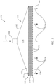
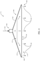
- FIG. 3 is a cross-sectional view of an example interior panel 158 that may be used in air distribution system 150 (shown in FIG. 2 ).
- each interior panel 158 includes a housing 160 having a side wall 162 defining an air inlet 164 and an air outlet 166.
- Air inlet 164 is coupled in flow communication with branched duct 152 (shown in FIG. 2 ) to enable conditioned air 126 to be channeled therethrough.
- Conditioned air 126 is channeled through housing 160 and then discharged from air outlet 166 directly into passenger cabin 108 (shown in FIG. 2 ).
- Interior panel 158 includes a nozzle 168 coupled to side wall 132 at air outlet 166.
- nozzle 168 includes a porous support structure 170, and at least one layer of material coupled thereto, as will be described in more detail below.
- Porous support structure 170 may be any flexible, semi-rigid, or rigid structure that enables airflow to be channeled therethrough.
- porous support structure 170 is in the form of a honeycomb structure having a plurality of hollow channels extending therethrough.
- an interior panel 171 includes porous support structure 170 that is in the form of a porous foam material, such as polyvinyl chloride, polyetherimide, polyvinylidene fluoride, and the like.
- Nozzle 168 has a first side 172 and a second side 174. Nozzle 168 extends across the entirety of air outlet 166 to define an air plenum 176 between air inlet 164 and first side 172 of nozzle 168. Perforations 154 are defined on second side 174 of nozzle 168. Extending nozzle 168 across air outlet 166 facilitates at least partially sealing housing 160, which enables air plenum 176 to be pressurized with conditioned air 126 channeled through air inlet 164. Accordingly, conditioned air 126 may be distributed across the entire surface area of first side 172. In one example, air inlet 164 is smaller in cross-sectional size than air outlet 166. Accordingly, side wall 162 of housing 160 may be tapered to increase in cross-sectional size from air inlet 164 to air outlet 166, which facilitates equalizing the pressure of conditioned air 126 across first side 172 of nozzle 168.
- nozzle 168 further includes a layer 178 of porous material coupled on at least one of first side 172 or second side 174 thereof.
- the porous material may be any material that enables interior panel 158 to function as described herein.
- the porous material may be a woven fibrous material, such as in a Leno weave pattern.
- the woven fibrous material may also be pre-impregnated with resin, adhesive, and the like (i.e., a "prepreg" composite).
- layer 178 extends across first side 172 and/or second side 174 to provide support to, and increase the rigidity of, porous support structure 170 while still permitting airflow therethrough.
- nozzle 168 also includes a layer 180 of decorative porous material coupled over layer 178 of porous material on second side 174. Accordingly, layer 180 defines the exterior surface of interior panel 158 that is visible to occupants of passenger cabin 108 (shown in FIG. 2 ). Layer 180 provides an improved aesthetic appearance, relative to layer 178, that is suitable for visibility to occupants of passenger cabin 108.
- the decorative porous material may be any material that enables interior panel 158 to function as described herein.
- layer 180 may be a thermoplastic sheet perforated by laser, chemical etching, abrasive blasting, contact with a drum roller with pins, or other suitable methods. Layer 180 may also be a cloth fabric material.
- air distribution systems 102 and 150 are operable to discharge conditioned air 126 from nozzles 146 and 168 into passenger cabin 108 at a velocity that is less than a threshold in which occupants of passenger cabin 108 may perceive an undesirable draft at their seat 120.
- air distribution systems 102 and 150 discharge conditioned air 126 at a velocity of less than about 500 feet per minute (ft/min) (i.e. 2.54 ms -1 ), less than about 250 ft/min (i.e. 1.27 ms -1 ), less than about 100 ft/min (i.e. 0.508 ms -1 ), or less than about 50 ft/min (i.e. 0.254 ms -1 ).
Landscapes
- Engineering & Computer Science (AREA)
- Aviation & Aerospace Engineering (AREA)
- Health & Medical Sciences (AREA)
- General Health & Medical Sciences (AREA)
- Pulmonology (AREA)
- Duct Arrangements (AREA)
- Air-Conditioning For Vehicles (AREA)
Abstract
Description
- The field relates generally to environmental control systems for use in confined spaces designed for human occupancy and, more specifically, to air distribution systems that facilitate minimizing airflow between passengers within confined spaces, such as aircraft passenger cabins.
- Some known pressurized aircraft use Environmental Control Systems ("ECS") to maintain cabin pressurization and to control cabin temperatures during flight. The ECS generally channels external air from the engines towards the aircraft cabin to pressurize the cabin. Some known systems condition the air using air conditioning packs, and the conditioned air is distributed within the cabin via an air distribution system. Some air distribution systems include multiple discrete nozzles located on either side of the interior of the aircraft fuselage above the passengers. The nozzles discharge conditioned air therefrom to generate two opposing and counter-rotating "cells" of air that circulate across the passenger seats before exiting the cabin through a return air grille located at the floor of the cabin. However, generating the counter-rotating cells requires the air to be discharged at relatively high velocities, which can generate undesirable noise pollution within the cabin. In addition, the counter-rotating cells may cause cross-circulation to occur between passengers, which is a significant consideration in view of recent global health crises.
- This section is intended to introduce the reader to various aspects of art that may be related to various aspects of the disclosure, which are described and/or claimed below. This discussion is believed to be helpful in providing the reader with background information to facilitate a better understanding of the various aspects of the present disclosure. Accordingly, it should be understood that these statements are to be read in this light, and not as admissions of prior art.
- One aspect is an aircraft including a side wall at least partially defining a passenger cabin and a crown section of the aircraft. The passenger cabin includes an overhead zone, a passenger zone, and a floor zone. An air supply duct is positioned within the crown section, and the air supply duct is configured to pressurize the crown section with air. At least one return air outlet is defined in the floor zone. An interior structure is coupled to the side wall and extends between the passenger cabin and the crown section. The interior structure includes a plurality of nozzles oriented to discharge the pressurized air from the crown section along an airflow path that extends downward through the overhead zone, downward through the passenger zone, and then towards the at least one return air outlet.
- Another aspect is an aircraft including a side wall at least partially defining a passenger cabin and a crown section of the aircraft. The passenger cabin includes an overhead zone, a passenger zone, and a floor zone. An air supply duct is positioned within the crown section, and the air supply duct is configured to channel air therethrough. At least one return air outlet is defined in the floor zone. A plurality of interior panels extend between the passenger cabin and the crown section, and each interior panel is coupled in flow communication with the air supply duct. The plurality of interior panels each include a plurality of perforations configured to discharge the air therefrom along an airflow path that extends downward through the overhead zone, downward through the passenger zone, and then towards the at least one return air outlet.
- Yet another aspect is an air distribution system including an air supply duct configured to channel air therethrough. A plurality of interior panels are each coupled in flow communication with the air supply duct, and the plurality of interior panels are coupled to each other in an array to define an interior structure. Each interior panel includes a housing having a side wall defining an air inlet and an air outlet. A porous support structure is coupled to the side wall at the air outlet. An air plenum is defined between the air inlet and a first side of the porous support structure, and a plurality of perforations configured to discharge the air therefrom are defined on a second side of the porous support structure.
- Various refinements exist of the features noted in relation to the above-mentioned aspects of the present disclosure. Further features may also be incorporated in the above-mentioned aspects of the present disclosure as well. These refinements and additional features may exist individually or in any combination. For instance, various features discussed below in relation to any of the illustrated embodiments of the present disclosure may be incorporated into any of the above-described aspects of the present disclosure, alone or in any combination.
- Further the embodiments are described in the following examples:
- Example 1. An aircraft comprising: a fuselage comprising a side wall at least partially defining a passenger cabin and a crown section of the aircraft, wherein the passenger cabin includes an overhead zone, a passenger zone, and a floor zone; an air supply duct positioned within the crown section, wherein the air supply duct is configured to channel air therethrough; at least one return air outlet defined in the floor zone; and a plurality of interior panels extending between the passenger cabin and the crown section, and each interior panel coupled in flow communication with the air supply duct, wherein the plurality of interior panels each comprise a plurality of perforations configured to discharge the air therefrom along an airflow path that extends downward through the overhead zone, downward through the passenger zone, and then towards the at least one return air outlet.
- Example 2. The aircraft in accordance with example 1, wherein each interior panel comprises: a housing comprising a side wall defining an air inlet and an air outlet; and a porous support structure coupled to the side wall at the air outlet, wherein an air plenum is defined between the air inlet and a first side of the porous support structure, and wherein the plurality of perforations are defined on a second side of the porous support structure.
- Example 3. The aircraft in accordance with example 2, wherein the side wall of the housing is tapered to increase in cross-sectional size from the air inlet to the air outlet.
- Example 4. The aircraft in accordance with examples 1-3, wherein each interior panel further comprises a layer of porous material coupled on at least one of the first side or the second side of the porous support structure.
- Example 5. The aircraft in accordance with example 4 further comprising a layer of decorative porous material coupled over the layer of porous material on the second side of the porous support structure.
- Example 6. The aircraft in accordance with examples 1-5 further comprising a branched duct coupled between the air supply duct and each interior panel.
- Example 7. The aircraft in accordance with examples 1-6, wherein the plurality of perforations are configured to discharge the air at a velocity of less than about 50 feet per minute (0.254 ms-1).
-
-
FIG. 1 is a cross-sectional view of an aircraft having an example air distribution system therein. -
FIG. 2 is a cross-sectional view of an aircraft having an alternative air distribution system therein. -
FIG. 3 is a cross-sectional view of an example interior panel that may be used in the air distribution system shown inFIG. 2 . -
FIG. 4 is a cross-sectional view of an alternative interior panel that may be used in the air distribution system shown inFIG. 2 . -
FIG. 5 is a side view of an example aircraft. - Corresponding reference characters indicate corresponding parts throughout the drawings.
- Examples described below include air distribution systems that facilitate minimizing airflow between passengers within confined spaces, such as aircraft passenger cabins. Example systems described provide a displacement ventilation scheme that generates bulk downward airflow within the confined space. In one example, the bulk downward airflow is discharged from above seated passengers in the confined space, downward past the passengers, and towards an outlet located at the floor of the confined space. This directional bulk downward airflow facilitates limiting cross-circulation between passengers seated next to each other in a respective row of an aircraft, for example. Example systems facilitate reducing the spread of airborne contaminants between nearby occupants, reducing noise and undesirable drafts, and limiting the formation of stagnant zones of circulation within the confined space.
-
FIG. 1 is a cross-sectional view of anaircraft 100 having an exampleair distribution system 102 therein.Aircraft 100 includes afuselage 104 having aside wall 106 that at least partially defines apassenger cabin 108 and acrown section 110 ofaircraft 100.Crown section 110 is positioned abovepassenger cabin 108, and aninterior structure 112 coupled toside wall 106 extends betweencrown section 110 andpassenger cabin 108.Passenger cabin 108 includes anoverhead zone 114, apassenger zone 116, and afloor zone 118.Passenger zone 116 includes a plurality ofseats 120 designed for human occupancy.Seats 120 are arranged in one ormore rows 122 acrosspassenger cabin 108.Overhead zone 114 is located abovepassenger seats 120, andfloor zone 118 is located below passenger seats 120. -
Air distribution system 102 includes anair supply duct 124 positioned withincrown section 110. In one example,interior structure 112 is arranged such thatcrown section 110 defines an open volume betweenside wall 106 andinterior structure 112.Air supply duct 124 is configured to channel conditionedair 126 therethrough, which is received from an environment control system (not shown) ofaircraft 100.Air supply duct 124 is configured to discharge theconditioned air 126 within thecrown section 110 to pressurizecrown section 110 withconditioned air 126.Pressurizing crown section 110 withconditioned air 126 facilitates supplyingpassenger cabin 108 withconditioned air 126. For example, at least onereturn air outlet 128 is defined infloor zone 118 and, as will be described in more detail below, conditionedair 126 discharged fromcrown section 110 is channeled throughpassenger cabin 108 and then exhausted frompassenger cabin 108 throughreturn air outlet 128. Referring toFIG. 1 , returnair outlet 128 is a return air grille defined inside wall 106 of fuselage. Alternatively, an air exhaust port may be defined in afloor 130 ofpassenger cabin 108. - Referring to
FIG. 1 ,air supply duct 124 includes aside wall 132 having a plurality ofairflow openings 134 defined therein.Airflow openings 134 provide flow communication fromair supply duct 124 tocrown section 110 to facilitate pressurization thereof.Airflow openings 134 may be any size and/or shape that enablesair distribution system 102 to function as described herein. For example,airflow openings 134 may be defined by multiple discrete holes or cutouts withinside wall 106 spaced along a length ofair supply duct 124 andfuselage 104. In an alternative example,air supply duct 124 is a piccolo type supply duct. -
Interior structure 112 is formed from a plurality of components, such asinterior panels 136,stowage bins 138,overhead consoles 140, and the like. In one example, at least some of components are spaced from each other to define gaps 142 therebetween. For example,interior panels 136,stowage bins 138, andoverhead consoles 140 may be coupled to each other, but also spaced from each other to provide airflow communication betweencrown section 110 andpassenger cabin 108 through gaps 142. In such an example, a blockingmember 144 may extend across at least one of the plurality of gaps 142. Blockingmember 144 is adapted to restrict visibility intocrown section 110 frompassenger cabin 108 while still permitting airflow communication therebetween. Components, such asoverhead consoles 140, may also be spaced fromside wall 106 to define additional gaps 142. - Accordingly, gaps 142 define a plurality of nozzles 146 within
interior structure 112. In an alternative example, the components themselves include airflow openings (not shown) defined therein to define nozzles 146 ofinterior structure 112. For example, gaps may be hidden behind light valences or other interior features to define additional nozzles 146 withininterior structure 112. Nozzles 146 are designed to discharge conditionedair 126 therefrom in a substantially downward direction relative tocrown section 110. Referring toFIG. 1 ,conditioned air 126 travels along anairflow path 148 that extends downward throughoverhead zone 114, downward throughpassenger zone 116, and then towardsreturn air outlet 128 located infloor zone 118. As a result of a combination of factors, such as airflow discharge velocity, discharge directionality ofconditioned air 126, and/or a pressure differential defined atreturn air outlet 128, for example,airflow path 148 extends downward throughpassenger cabin 108 to facilitate limiting cross-circulation between passengers seated next to each other in arespective row 122 ofaircraft 100. As used herein, "downward" refers to a one-way direction of travel that reduces in height between two points, such as from nozzles 146 to returnair outlet 128, without the direction of travel increasing in height between the two points. -
FIG. 2 is a cross-sectional view ofaircraft 100 having an alternativeair distribution system 150 therein. In the illustrated example,interior structure 112 includes a plurality ofinterior panels 136 extending betweencrown section 110 andpassenger cabin 108.Interior panels 136 may be ceiling panels, side wall panels, overhead console panels, and the like, which are designed to be visible and aesthetically pleasing to the occupants ofpassenger cabin 108. Eachinterior panel 136 is coupled in flow communication withair supply duct 124. For example, abranched duct 152 may be coupled betweenair supply duct 124 and eachinterior panel 136 to enable conditionedair 126 to be channeled fromair supply duct 124 to the plurality ofinterior panels 136. As will be described in more detail below, eachinterior panel 136 includes a plurality of perforations 154 (shown inFIG. 3 ) configured to discharge conditionedair 126 therefrom in a substantially downward direction relative tocrown section 110. - As illustrated in
FIG. 2 ,conditioned air 126 travels along anairflow path 156 that extends downward throughoverhead zone 114, downward throughpassenger zone 116, and then towardsreturn air outlet 128 located infloor zone 118. Similar toairflow path 148,airflow path 156 extends downward throughpassenger cabin 108 to facilitate limiting cross-circulation between passengers seated next to each other in arespective row 122 ofaircraft 100. -
FIG. 3 is a cross-sectional view of an exampleinterior panel 158 that may be used in air distribution system 150 (shown inFIG. 2 ). In the illustrated example, eachinterior panel 158 includes ahousing 160 having aside wall 162 defining anair inlet 164 and anair outlet 166.Air inlet 164 is coupled in flow communication with branched duct 152 (shown inFIG. 2 ) to enable conditionedair 126 to be channeled therethrough. Conditionedair 126 is channeled throughhousing 160 and then discharged fromair outlet 166 directly into passenger cabin 108 (shown inFIG. 2 ). -
Interior panel 158 includes anozzle 168 coupled toside wall 132 atair outlet 166. In the illustrated example,nozzle 168 includes aporous support structure 170, and at least one layer of material coupled thereto, as will be described in more detail below.Porous support structure 170 may be any flexible, semi-rigid, or rigid structure that enables airflow to be channeled therethrough. In the illustrated example,porous support structure 170 is in the form of a honeycomb structure having a plurality of hollow channels extending therethrough. Alternatively, as shown inFIG. 4 , aninterior panel 171 includesporous support structure 170 that is in the form of a porous foam material, such as polyvinyl chloride, polyetherimide, polyvinylidene fluoride, and the like. -
Nozzle 168 has afirst side 172 and asecond side 174.Nozzle 168 extends across the entirety ofair outlet 166 to define anair plenum 176 betweenair inlet 164 andfirst side 172 ofnozzle 168.Perforations 154 are defined onsecond side 174 ofnozzle 168. Extendingnozzle 168 acrossair outlet 166 facilitates at least partially sealinghousing 160, which enablesair plenum 176 to be pressurized withconditioned air 126 channeled throughair inlet 164. Accordingly,conditioned air 126 may be distributed across the entire surface area offirst side 172. In one example,air inlet 164 is smaller in cross-sectional size thanair outlet 166. Accordingly,side wall 162 ofhousing 160 may be tapered to increase in cross-sectional size fromair inlet 164 toair outlet 166, which facilitates equalizing the pressure ofconditioned air 126 acrossfirst side 172 ofnozzle 168. - Referring again to
FIG. 3 ,nozzle 168 further includes alayer 178 of porous material coupled on at least one offirst side 172 orsecond side 174 thereof. The porous material may be any material that enablesinterior panel 158 to function as described herein. For example, the porous material may be a woven fibrous material, such as in a Leno weave pattern. The woven fibrous material may also be pre-impregnated with resin, adhesive, and the like (i.e., a "prepreg" composite). Accordingly,layer 178 extends acrossfirst side 172 and/orsecond side 174 to provide support to, and increase the rigidity of,porous support structure 170 while still permitting airflow therethrough. - In the illustrated example,
nozzle 168 also includes alayer 180 of decorative porous material coupled overlayer 178 of porous material onsecond side 174. Accordingly,layer 180 defines the exterior surface ofinterior panel 158 that is visible to occupants of passenger cabin 108 (shown inFIG. 2 ).Layer 180 provides an improved aesthetic appearance, relative tolayer 178, that is suitable for visibility to occupants ofpassenger cabin 108. The decorative porous material may be any material that enablesinterior panel 158 to function as described herein. For example,layer 180 may be a thermoplastic sheet perforated by laser, chemical etching, abrasive blasting, contact with a drum roller with pins, or other suitable methods.Layer 180 may also be a cloth fabric material. Accordingly,interior panel 158 is provided with a plurality ofperforations 154 onsecond side 174 thereof. In one example,perforations 154 are distributed generally substantially uniformly acrosslayer 180 such thatconditioned air 126 discharged therefrom is in the form of distributed bulk airflow. Thus, airflow is provided across the exposed surface area oflayer 180. - In operation,
conditioned air 126 is discharged fromnozzles 146 and 168 at a flow rate greater than a first threshold, and at a velocity less than a second threshold, in order to satisfy a desired airflow recirculation rate throughpassenger cabin 108. The flow rate threshold is based at least partially on the number ofoccupants aircraft 100 is designed to transport. Accordingly, in one example,air distribution systems nozzles 146 and 168 at a flow rate greater than about 0.25 pounds per minute per occupant (lbs/min/occupant) i.e. 0.11 kg/min/occupant, greater than about 0.4 lbs/min/occupant (0.18 kg/min/occupant), greater than about 0.5 lbs/min/occupant (0.22 kg/min/occupant), or greater than about 0.55 lbs/min/occupant (0.25 kg/min/occupant). The velocity threshold is based at least partially on a perceived comfort level of occupants ofpassenger cabin 108. Accordingly, in operation,air distribution systems air 126 fromnozzles 146 and 168 intopassenger cabin 108 at a velocity that is less than a threshold in which occupants ofpassenger cabin 108 may perceive an undesirable draft at theirseat 120. Accordingly,air distribution systems air 126 at a velocity of less than about 500 feet per minute (ft/min) (i.e. 2.54 ms-1), less than about 250 ft/min (i.e. 1.27 ms-1), less than about 100 ft/min (i.e. 0.508 ms-1), or less than about 50 ft/min (i.e. 0.254 ms-1). - The systems and methods described are not limited to the specific embodiments described herein, but rather, components of the systems and/or steps of the methods may be utilized independently and separately from other components and/or steps described herein.
- Although specific features of various embodiments of the disclosure may be shown in some drawings and not in others, this is for convenience only. In accordance with the principles of the disclosure, any feature of a drawing may be referenced and/or claimed in combination with any feature of any other drawing.
- As used herein, an element or step recited in the singular and proceeded with the word "a" or "an" should be understood as not excluding plural elements or steps unless such exclusion is explicitly recited. Furthermore, references to "one embodiment" of the present invention or the "example embodiment" are not intended to be interpreted as excluding the existence of additional embodiments that also incorporate the recited features.
- This written description uses examples to disclose various implementations, including the best mode, and also to enable any person skilled in the art to practice the various implementations, including making and using any devices or systems and performing any incorporated methods. The patentable scope of the disclosure is defined by the claims, and may include other examples that occur to those skilled in the art after reading this specification. Such other examples are intended to be within the scope of the claims if they have structural elements that do not differ from the literal language of the claims, or if they include equivalent structural elements with insubstantial differences from the literal language of the claims.
Claims (13)
- An aircraft (100) comprising:a fuselage (104) comprising a side wall (106) at least partially defining a passenger cabin (108) and a crown section (110) of the aircraft, wherein the passenger cabin includes an overhead zone (114), a passenger zone (116), and a floor zone (118);an air supply duct (124) positioned within the crown section (110), wherein the air supply duct (124) is configured to pressurize the crown section (110) with air;at least one return air outlet (128) defined in the floor zone (118); andan interior structure (112) coupled to the side wall (106) and extending between the passenger cabin (108) and the crown section (110), the interior structure (112) comprising a plurality of nozzles (146) oriented to discharge the air from the crown section (110) along an airflow path (148) that extends downward through the overhead zone, downward through the passenger zone (116), and then towards the at least one return air outlet (128).
- The aircraft (100) in accordance with Claim 1, wherein the interior structure (112) comprises a plurality of components, at least some of the plurality of components being spaced from each other to define a gap (142) therebetween that defines a respective nozzle of the plurality of nozzles (146).
- The aircraft (100) in accordance with Claim 2, wherein the interior structure (112) further comprises a blocking member (144) extending across the gap, the blocking member (144) configured to restrict visibility into the crown section (110) from the passenger cabin (108).
- The aircraft (100) in accordance with Claims 1-3, wherein the interior structure (112) comprises at least one of an interior panel (136), a stowage bin (138), or an overhead console (140).
- The aircraft (100) in accordance with Claims 1-4, wherein the interior structure (112) is spaced from the side wall to define a gap (142) therebetween, wherein the gap defines a respective nozzle of the plurality of nozzles (146).
- The aircraft (100) in accordance with Claims 1-5, wherein the plurality of nozzles (146) are configured to discharge the pressurized air at a velocity of less than about 50 feet per minute (i.e. 0.254 ms-1).
- The aircraft (100) in accordance with Claims 1-6, wherein the air supply duct comprises a side wall and a plurality of airflow openings defined in the side wall.
- The aircraft (100) of claim 1 comprising an air distribution system (150) comprising:the air supply duct (124) configured to channel air therethrough;a plurality of interior panels (158) each coupled in flow communication with the air supply duct, wherein the plurality of interior panels (158) are coupled to each other in an array to define an interior structure, each interior panel comprising:a housing (160) comprising a side wall (162) defining an air inlet (164) and an air outlet (166); anda porous support structure (170) coupled to the side wall at the air outlet, wherein an air plenum is defined between the air inlet and a first side of the porous support structure, and wherein a plurality of perforations configured to discharge the air therefrom are defined on a second side of the porous support structure.
- The aircraft (100) in accordance with Claim 8, wherein the side wall (162) of the housing (160) is tapered to increase in cross-sectional size from the air inlet (164) to the air outlet (166).
- The aircraft (100) in accordance with Claims 8-9, wherein each interior panel further comprises a layer of porous material coupled on at least one of the first side or the second side of the porous support structure (170).
- The aircraft (100) in accordance with Claim 10 further comprising a layer of decorative porous material coupled over the layer of porous material on the second side of the porous support structure (170).
- The aircraft (100) in accordance with Claims 8-11, wherein the porous support structure (170) is formed from an open cell foam material or a honeycomb structure.
- The aircraft (100) in accordance with Claims 8-12 further comprising a branched duct (152) coupled between the air supply duct (124) and the air inlet of each interior panel (136).
Applications Claiming Priority (1)
| Application Number | Priority Date | Filing Date | Title |
|---|---|---|---|
| US202063055455P | 2020-07-23 | 2020-07-23 |
Publications (2)
| Publication Number | Publication Date |
|---|---|
| EP3943394A1 true EP3943394A1 (en) | 2022-01-26 |
| EP3943394B1 EP3943394B1 (en) | 2025-09-03 |
Family
ID=76920621
Family Applications (1)
| Application Number | Title | Priority Date | Filing Date |
|---|---|---|---|
| EP21185438.5A Active EP3943394B1 (en) | 2020-07-23 | 2021-07-13 | Air distribution system for use in an aircraft |
Country Status (4)
| Country | Link |
|---|---|
| US (1) | US12049323B2 (en) |
| EP (1) | EP3943394B1 (en) |
| JP (1) | JP7830037B2 (en) |
| CN (1) | CN113968344A (en) |
Cited By (2)
| Publication number | Priority date | Publication date | Assignee | Title |
|---|---|---|---|---|
| US20210387737A1 (en) * | 2020-06-10 | 2021-12-16 | Walter Dorwin Teague Associates, Inc. | Passenger air shield |
| CN115402517A (en) * | 2022-11-01 | 2022-11-29 | 西安羚控电子科技有限公司 | Air door control mechanism and aircraft |
Families Citing this family (1)
| Publication number | Priority date | Publication date | Assignee | Title |
|---|---|---|---|---|
| JP7840644B2 (en) * | 2020-07-23 | 2026-04-06 | ザ・ボーイング・カンパニー | Environmental control system for use in aircraft |
Citations (6)
| Publication number | Priority date | Publication date | Assignee | Title |
|---|---|---|---|---|
| US4742760A (en) * | 1987-07-06 | 1988-05-10 | The Boeing Company | Aircraft cabin ventilation system |
| US20070164158A1 (en) * | 2005-12-21 | 2007-07-19 | Airbus Deutschland Gmbh | Aircraft Fuselage With Upper And Lower Deck |
| US20090061754A1 (en) * | 2007-08-31 | 2009-03-05 | The Boeing Company | Aircraft Cabin Airflow Nozzles and Associated Systems and Methods |
| DE102008026093B4 (en) * | 2008-05-30 | 2014-02-13 | Airbus Operations Gmbh | System and method for ventilating an aircraft cabin |
| US20160318614A1 (en) * | 2015-05-01 | 2016-11-03 | The Boeing Company | Methods and apparatuses for integrated noise control and flow control in an aircraft environmental control system |
| EP2851298B1 (en) * | 2013-08-27 | 2017-12-13 | The Boeing Company | Air diffuser system |
Family Cites Families (24)
| Publication number | Priority date | Publication date | Assignee | Title |
|---|---|---|---|---|
| US3687054A (en) * | 1970-11-24 | 1972-08-29 | Lockheed Aircraft Corp | Air outlet apparatus |
| DE19509773C1 (en) * | 1995-03-17 | 1996-06-27 | Daimler Benz Aerospace Airbus | Ventilating system for reducing concentration of impurities in aircraft passenger area |
| US5897079A (en) * | 1997-08-18 | 1999-04-27 | Mcdonnell Douglas Corporation | Air curtain insulating system for aircraft cabin |
| US6413159B1 (en) * | 2000-06-28 | 2002-07-02 | The Boeing Company | Airplane cabin overhead air outlets |
| DE10361654B4 (en) * | 2003-12-30 | 2008-09-04 | Airbus Deutschland Gmbh | Method and device for air conditioning of aircraft cabins |
| US8206475B2 (en) * | 2006-06-23 | 2012-06-26 | Veft Aerospace Technology Inc. | Entrainment air flow control and filtration devices |
| DE102010034028A1 (en) * | 2010-08-11 | 2012-02-16 | Diehl Aircabin Gmbh | Sandwich panel for an interior wall paneling of a passenger cabin |
| FI122638B (en) * | 2010-10-21 | 2012-04-30 | Abb Oy | Drive configuration |
| FR2971230B1 (en) * | 2011-02-09 | 2013-02-15 | Liebherr Aerospace Toulouse Sas | ANTI-CONDENSATION DEVICE AND METHOD FOR AN AIRCRAFT |
| US9889939B2 (en) | 2012-06-06 | 2018-02-13 | The Boeing Company | Environmental control system and methods of operating same |
| US10081429B2 (en) * | 2014-07-21 | 2018-09-25 | The Boeing Company | Air diffuser systems, methods, and apparatuses |
| CN105292493B (en) * | 2015-10-30 | 2018-04-03 | 天津大学 | Air conditioning system with downward-feeding and upward-returning airflow channel suitable for passenger plane cabin |
| US11059592B2 (en) * | 2016-10-13 | 2021-07-13 | Gulfstream Aerospace Corporation | Coaxial fluid vent and electronic control for a fluid valve for aircraft |
| DE102017112594A1 (en) * | 2017-06-08 | 2018-12-13 | Airbus Operations Gmbh | Air distribution system for an aircraft cabin |
| DE102017210007A1 (en) * | 2017-06-14 | 2018-12-20 | Airbus Operations Gmbh | Aircraft area, aircraft and method for loading an aircraft area |
| DE102017119751A1 (en) * | 2017-08-29 | 2019-02-28 | Airbus Operations Gmbh | Canopy panel panel for an aircraft cabin |
| WO2019119115A1 (en) * | 2017-12-18 | 2019-06-27 | Bombardier Inc. | Overhead flow distribution assembly for aircraft cabin |
| DE102018007420A1 (en) * | 2018-09-20 | 2020-03-26 | Airbus Operations Gmbh | Air distribution system for an aircraft cabin |
| US11267572B2 (en) * | 2018-11-08 | 2022-03-08 | The Boeing Company | Aircraft air distribution assembly |
| JP7281908B2 (en) * | 2019-01-18 | 2023-05-26 | 三菱航空機株式会社 | Aircraft air conditioning duct structure, aircraft, and aircraft manufacturing method |
| US11091270B2 (en) * | 2019-01-22 | 2021-08-17 | The Boeing Company | Buoyancy driven passive vehicle air drying system and method |
| US11255583B2 (en) * | 2019-02-05 | 2022-02-22 | The Boeing Company | Dry ice-based cooling systems |
| US12151820B2 (en) | 2020-06-18 | 2024-11-26 | B/E Aerospace, Inc. | Software controlled air flow management |
| US12214886B2 (en) | 2020-08-28 | 2025-02-04 | The Boeing Company | Ventilation systems and methods for internal cabins of vehicles |
-
2021
- 2021-06-17 JP JP2021100866A patent/JP7830037B2/en active Active
- 2021-07-06 US US17/368,137 patent/US12049323B2/en active Active
- 2021-07-13 EP EP21185438.5A patent/EP3943394B1/en active Active
- 2021-07-15 CN CN202110800038.7A patent/CN113968344A/en active Pending
Patent Citations (6)
| Publication number | Priority date | Publication date | Assignee | Title |
|---|---|---|---|---|
| US4742760A (en) * | 1987-07-06 | 1988-05-10 | The Boeing Company | Aircraft cabin ventilation system |
| US20070164158A1 (en) * | 2005-12-21 | 2007-07-19 | Airbus Deutschland Gmbh | Aircraft Fuselage With Upper And Lower Deck |
| US20090061754A1 (en) * | 2007-08-31 | 2009-03-05 | The Boeing Company | Aircraft Cabin Airflow Nozzles and Associated Systems and Methods |
| DE102008026093B4 (en) * | 2008-05-30 | 2014-02-13 | Airbus Operations Gmbh | System and method for ventilating an aircraft cabin |
| EP2851298B1 (en) * | 2013-08-27 | 2017-12-13 | The Boeing Company | Air diffuser system |
| US20160318614A1 (en) * | 2015-05-01 | 2016-11-03 | The Boeing Company | Methods and apparatuses for integrated noise control and flow control in an aircraft environmental control system |
Non-Patent Citations (1)
| Title |
|---|
| ZHANG ET AL: "Novel air distribution systems for commercial aircraft cabins", BUILDING AND ENVIRONMENT, PERGAMON PRESS, OXFORD, GB, vol. 42, no. 4, 6 December 2006 (2006-12-06), pages 1675 - 1684, XP005794646, ISSN: 0360-1323, DOI: 10.1016/J.BUILDENV.2006.02.014 * |
Cited By (3)
| Publication number | Priority date | Publication date | Assignee | Title |
|---|---|---|---|---|
| US20210387737A1 (en) * | 2020-06-10 | 2021-12-16 | Walter Dorwin Teague Associates, Inc. | Passenger air shield |
| CN115402517A (en) * | 2022-11-01 | 2022-11-29 | 西安羚控电子科技有限公司 | Air door control mechanism and aircraft |
| CN115402517B (en) * | 2022-11-01 | 2023-02-28 | 西安羚控电子科技有限公司 | Air door control mechanism and aircraft |
Also Published As
| Publication number | Publication date |
|---|---|
| US12049323B2 (en) | 2024-07-30 |
| JP2022022105A (en) | 2022-02-03 |
| US20220024594A1 (en) | 2022-01-27 |
| CN113968344A (en) | 2022-01-25 |
| EP3943394B1 (en) | 2025-09-03 |
| JP7830037B2 (en) | 2026-03-16 |
Similar Documents
| Publication | Publication Date | Title |
|---|---|---|
| US12049323B2 (en) | Air distribution system for use in an aircraft | |
| EP0301606B1 (en) | Aircraft cabin ventilation system | |
| US9561855B2 (en) | Alternate directional momentum ventilation nozzle for passenger cabins | |
| EP0292033B1 (en) | Dual nozzle cabin ventilation system | |
| EP3960630B1 (en) | Air curtain systems and methods for vehicle cabins | |
| US20100081369A1 (en) | Personal ventilation in an aircraft environment | |
| EP2671801B1 (en) | Environmental control system and methods of operating same | |
| EP3088303B1 (en) | Apparatus for integrated noise control and flow control in an aircraft environmental control system | |
| US6189831B1 (en) | Noren-type separating apparatus for separating a smoking area and a non-smoking area in an airliner with respect to cigarette smoke | |
| US7029065B2 (en) | Ventilated seating system with improved low pressure performance | |
| US20130040546A1 (en) | Aircraft and method for climatizing at least a part-region of the interior of an aircraft | |
| EP1167184B1 (en) | Airplane cabin overhead air outlets | |
| JPH01218410A (en) | Cushion for seat | |
| EP3144225B1 (en) | Aircraft circulation system for passenger cabins | |
| EP3960629B1 (en) | VENTILATION SYSTEMS AND METHODS FOR VEHICLE INTERIORS | |
| CN103204045B (en) | For the air regulation of inside and/or the equipment of ventilation | |
| RU2616490C2 (en) | Vehicle air conditioning system and railway vehicle equipped with such system | |
| EP3932809B1 (en) | Air curtain systems and methods for internal cabins of vehicles | |
| US20100317277A1 (en) | Air outlet | |
| CN101590912A (en) | A passenger cabin air supply and exhaust system | |
| CN114104295A (en) | Ventilation system and method for an interior compartment of a vehicle | |
| US11577582B2 (en) | HVAC air distribution device to promote temperature stratification | |
| US20180370610A1 (en) | Aircraft fuselage frame equipped with airbag and riser duct closure cover | |
| JP7281908B2 (en) | Aircraft air conditioning duct structure, aircraft, and aircraft manufacturing method | |
| WO2018224061A1 (en) | Air conditioning diffuser |
Legal Events
| Date | Code | Title | Description |
|---|---|---|---|
| PUAI | Public reference made under article 153(3) epc to a published international application that has entered the european phase |
Free format text: ORIGINAL CODE: 0009012 |
|
| STAA | Information on the status of an ep patent application or granted ep patent |
Free format text: STATUS: THE APPLICATION HAS BEEN PUBLISHED |
|
| AK | Designated contracting states |
Kind code of ref document: A1 Designated state(s): AL AT BE BG CH CY CZ DE DK EE ES FI FR GB GR HR HU IE IS IT LI LT LU LV MC MK MT NL NO PL PT RO RS SE SI SK SM TR |
|
| STAA | Information on the status of an ep patent application or granted ep patent |
Free format text: STATUS: REQUEST FOR EXAMINATION WAS MADE |
|
| 17P | Request for examination filed |
Effective date: 20220620 |
|
| RBV | Designated contracting states (corrected) |
Designated state(s): AL AT BE BG CH CY CZ DE DK EE ES FI FR GB GR HR HU IE IS IT LI LT LU LV MC MK MT NL NO PL PT RO RS SE SI SK SM TR |
|
| RAP3 | Party data changed (applicant data changed or rights of an application transferred) |
Owner name: THE BOEING COMPANY |
|
| STAA | Information on the status of an ep patent application or granted ep patent |
Free format text: STATUS: EXAMINATION IS IN PROGRESS |
|
| 17Q | First examination report despatched |
Effective date: 20230403 |
|
| GRAP | Despatch of communication of intention to grant a patent |
Free format text: ORIGINAL CODE: EPIDOSNIGR1 |
|
| STAA | Information on the status of an ep patent application or granted ep patent |
Free format text: STATUS: GRANT OF PATENT IS INTENDED |
|
| INTG | Intention to grant announced |
Effective date: 20250519 |
|
| GRAS | Grant fee paid |
Free format text: ORIGINAL CODE: EPIDOSNIGR3 |
|
| P01 | Opt-out of the competence of the unified patent court (upc) registered |
Free format text: CASE NUMBER: APP_28414/2025 Effective date: 20250613 |
|
| GRAA | (expected) grant |
Free format text: ORIGINAL CODE: 0009210 |
|
| STAA | Information on the status of an ep patent application or granted ep patent |
Free format text: STATUS: THE PATENT HAS BEEN GRANTED |
|
| AK | Designated contracting states |
Kind code of ref document: B1 Designated state(s): AL AT BE BG CH CY CZ DE DK EE ES FI FR GB GR HR HU IE IS IT LI LT LU LV MC MK MT NL NO PL PT RO RS SE SI SK SM TR |
|
| REG | Reference to a national code |
Ref country code: CH Ref legal event code: EP |
|
| REG | Reference to a national code |
Ref country code: DE Ref legal event code: R096 Ref document number: 602021037578 Country of ref document: DE |
|
| REG | Reference to a national code |
Ref country code: IE Ref legal event code: FG4D |
|
| REG | Reference to a national code |
Ref country code: NL Ref legal event code: MP Effective date: 20250903 |
|
| PG25 | Lapsed in a contracting state [announced via postgrant information from national office to epo] |
Ref country code: NO Free format text: LAPSE BECAUSE OF FAILURE TO SUBMIT A TRANSLATION OF THE DESCRIPTION OR TO PAY THE FEE WITHIN THE PRESCRIBED TIME-LIMIT Effective date: 20251203 |
|
| REG | Reference to a national code |
Ref country code: LT Ref legal event code: MG9D |
|
| PG25 | Lapsed in a contracting state [announced via postgrant information from national office to epo] |
Ref country code: FI Free format text: LAPSE BECAUSE OF FAILURE TO SUBMIT A TRANSLATION OF THE DESCRIPTION OR TO PAY THE FEE WITHIN THE PRESCRIBED TIME-LIMIT Effective date: 20250903 |
|
| PG25 | Lapsed in a contracting state [announced via postgrant information from national office to epo] |
Ref country code: HR Free format text: LAPSE BECAUSE OF FAILURE TO SUBMIT A TRANSLATION OF THE DESCRIPTION OR TO PAY THE FEE WITHIN THE PRESCRIBED TIME-LIMIT Effective date: 20250903 |
|
| PG25 | Lapsed in a contracting state [announced via postgrant information from national office to epo] |
Ref country code: GR Free format text: LAPSE BECAUSE OF FAILURE TO SUBMIT A TRANSLATION OF THE DESCRIPTION OR TO PAY THE FEE WITHIN THE PRESCRIBED TIME-LIMIT Effective date: 20251204 |
|
| PG25 | Lapsed in a contracting state [announced via postgrant information from national office to epo] |
Ref country code: SE Free format text: LAPSE BECAUSE OF FAILURE TO SUBMIT A TRANSLATION OF THE DESCRIPTION OR TO PAY THE FEE WITHIN THE PRESCRIBED TIME-LIMIT Effective date: 20250903 |
|
| PG25 | Lapsed in a contracting state [announced via postgrant information from national office to epo] |
Ref country code: LV Free format text: LAPSE BECAUSE OF FAILURE TO SUBMIT A TRANSLATION OF THE DESCRIPTION OR TO PAY THE FEE WITHIN THE PRESCRIBED TIME-LIMIT Effective date: 20250903 |
|
| PG25 | Lapsed in a contracting state [announced via postgrant information from national office to epo] |
Ref country code: BG Free format text: LAPSE BECAUSE OF FAILURE TO SUBMIT A TRANSLATION OF THE DESCRIPTION OR TO PAY THE FEE WITHIN THE PRESCRIBED TIME-LIMIT Effective date: 20250903 Ref country code: PL Free format text: LAPSE BECAUSE OF FAILURE TO SUBMIT A TRANSLATION OF THE DESCRIPTION OR TO PAY THE FEE WITHIN THE PRESCRIBED TIME-LIMIT Effective date: 20250903 |
|
| PG25 | Lapsed in a contracting state [announced via postgrant information from national office to epo] |
Ref country code: RS Free format text: LAPSE BECAUSE OF FAILURE TO SUBMIT A TRANSLATION OF THE DESCRIPTION OR TO PAY THE FEE WITHIN THE PRESCRIBED TIME-LIMIT Effective date: 20251203 |
|
| PG25 | Lapsed in a contracting state [announced via postgrant information from national office to epo] |
Ref country code: ES Free format text: LAPSE BECAUSE OF FAILURE TO SUBMIT A TRANSLATION OF THE DESCRIPTION OR TO PAY THE FEE WITHIN THE PRESCRIBED TIME-LIMIT Effective date: 20250903 |
|
| REG | Reference to a national code |
Ref country code: AT Ref legal event code: MK05 Ref document number: 1832778 Country of ref document: AT Kind code of ref document: T Effective date: 20250903 |
|
| PG25 | Lapsed in a contracting state [announced via postgrant information from national office to epo] |
Ref country code: NL Free format text: LAPSE BECAUSE OF FAILURE TO SUBMIT A TRANSLATION OF THE DESCRIPTION OR TO PAY THE FEE WITHIN THE PRESCRIBED TIME-LIMIT Effective date: 20250903 |
|
| PG25 | Lapsed in a contracting state [announced via postgrant information from national office to epo] |
Ref country code: SM Free format text: LAPSE BECAUSE OF FAILURE TO SUBMIT A TRANSLATION OF THE DESCRIPTION OR TO PAY THE FEE WITHIN THE PRESCRIBED TIME-LIMIT Effective date: 20250903 |
|
| PG25 | Lapsed in a contracting state [announced via postgrant information from national office to epo] |
Ref country code: AT Free format text: LAPSE BECAUSE OF FAILURE TO SUBMIT A TRANSLATION OF THE DESCRIPTION OR TO PAY THE FEE WITHIN THE PRESCRIBED TIME-LIMIT Effective date: 20250903 |
|
| PG25 | Lapsed in a contracting state [announced via postgrant information from national office to epo] |
Ref country code: IT Free format text: LAPSE BECAUSE OF FAILURE TO SUBMIT A TRANSLATION OF THE DESCRIPTION OR TO PAY THE FEE WITHIN THE PRESCRIBED TIME-LIMIT Effective date: 20250903 |
|
| PG25 | Lapsed in a contracting state [announced via postgrant information from national office to epo] |
Ref country code: IS Free format text: LAPSE BECAUSE OF FAILURE TO SUBMIT A TRANSLATION OF THE DESCRIPTION OR TO PAY THE FEE WITHIN THE PRESCRIBED TIME-LIMIT Effective date: 20260103 |
|
| PG25 | Lapsed in a contracting state [announced via postgrant information from national office to epo] |
Ref country code: CZ Free format text: LAPSE BECAUSE OF FAILURE TO SUBMIT A TRANSLATION OF THE DESCRIPTION OR TO PAY THE FEE WITHIN THE PRESCRIBED TIME-LIMIT Effective date: 20250903 Ref country code: PT Free format text: LAPSE BECAUSE OF FAILURE TO SUBMIT A TRANSLATION OF THE DESCRIPTION OR TO PAY THE FEE WITHIN THE PRESCRIBED TIME-LIMIT Effective date: 20260105 |
|
| PG25 | Lapsed in a contracting state [announced via postgrant information from national office to epo] |
Ref country code: SK Free format text: LAPSE BECAUSE OF FAILURE TO SUBMIT A TRANSLATION OF THE DESCRIPTION OR TO PAY THE FEE WITHIN THE PRESCRIBED TIME-LIMIT Effective date: 20250903 Ref country code: EE Free format text: LAPSE BECAUSE OF FAILURE TO SUBMIT A TRANSLATION OF THE DESCRIPTION OR TO PAY THE FEE WITHIN THE PRESCRIBED TIME-LIMIT Effective date: 20250903 |