EP3943391A1 - Sanitizing galley cart for an internal cabin of a vehicle - Google Patents
Sanitizing galley cart for an internal cabin of a vehicle Download PDFInfo
- Publication number
- EP3943391A1 EP3943391A1 EP21178757.7A EP21178757A EP3943391A1 EP 3943391 A1 EP3943391 A1 EP 3943391A1 EP 21178757 A EP21178757 A EP 21178757A EP 3943391 A1 EP3943391 A1 EP 3943391A1
- Authority
- EP
- European Patent Office
- Prior art keywords
- galley
- cart
- light sources
- galley cart
- light
- Prior art date
- Legal status (The legal status is an assumption and is not a legal conclusion. Google has not performed a legal analysis and makes no representation as to the accuracy of the status listed.)
- Granted
Links
Images






Classifications
-
- B—PERFORMING OPERATIONS; TRANSPORTING
- B64—AIRCRAFT; AVIATION; COSMONAUTICS
- B64F—GROUND OR AIRCRAFT-CARRIER-DECK INSTALLATIONS SPECIALLY ADAPTED FOR USE IN CONNECTION WITH AIRCRAFT; DESIGNING, MANUFACTURING, ASSEMBLING, CLEANING, MAINTAINING OR REPAIRING AIRCRAFT, NOT OTHERWISE PROVIDED FOR; HANDLING, TRANSPORTING, TESTING OR INSPECTING AIRCRAFT COMPONENTS, NOT OTHERWISE PROVIDED FOR
- B64F5/00—Designing, manufacturing, assembling, cleaning, maintaining or repairing aircraft, not otherwise provided for; Handling, transporting, testing or inspecting aircraft components, not otherwise provided for
- B64F5/30—Cleaning aircraft
-
- A—HUMAN NECESSITIES
- A61—MEDICAL OR VETERINARY SCIENCE; HYGIENE
- A61L—METHODS OR APPARATUS FOR STERILISING MATERIALS OR OBJECTS IN GENERAL; DISINFECTION, STERILISATION OR DEODORISATION OF AIR; CHEMICAL ASPECTS OF BANDAGES, DRESSINGS, ABSORBENT PADS OR SURGICAL ARTICLES; MATERIALS FOR BANDAGES, DRESSINGS, ABSORBENT PADS OR SURGICAL ARTICLES
- A61L2/00—Disinfection or sterilisation of materials or objects, in general; Accessories therefor
- A61L2/02—Disinfection or sterilisation of materials or objects, in general; Accessories therefor using physical processes
- A61L2/08—Radiation
- A61L2/10—Ultraviolet [UV] radiation
-
- A—HUMAN NECESSITIES
- A61—MEDICAL OR VETERINARY SCIENCE; HYGIENE
- A61L—METHODS OR APPARATUS FOR STERILISING MATERIALS OR OBJECTS IN GENERAL; DISINFECTION, STERILISATION OR DEODORISATION OF AIR; CHEMICAL ASPECTS OF BANDAGES, DRESSINGS, ABSORBENT PADS OR SURGICAL ARTICLES; MATERIALS FOR BANDAGES, DRESSINGS, ABSORBENT PADS OR SURGICAL ARTICLES
- A61L2/00—Disinfection or sterilisation of materials or objects, in general; Accessories therefor
- A61L2/26—Accessories
-
- B—PERFORMING OPERATIONS; TRANSPORTING
- B64—AIRCRAFT; AVIATION; COSMONAUTICS
- B64D—EQUIPMENT FOR FITTING IN OR TO AIRCRAFT; FLIGHT SUITS; PARACHUTES; ARRANGEMENT OR MOUNTING OF POWER PLANTS OR PROPULSION TRANSMISSIONS IN AIRCRAFT
- B64D11/00—Passenger or crew accommodation; Flight-deck installations not otherwise provided for
-
- B—PERFORMING OPERATIONS; TRANSPORTING
- B64—AIRCRAFT; AVIATION; COSMONAUTICS
- B64D—EQUIPMENT FOR FITTING IN OR TO AIRCRAFT; FLIGHT SUITS; PARACHUTES; ARRANGEMENT OR MOUNTING OF POWER PLANTS OR PROPULSION TRANSMISSIONS IN AIRCRAFT
- B64D11/00—Passenger or crew accommodation; Flight-deck installations not otherwise provided for
- B64D11/0007—Devices specially adapted for food or beverage distribution services
-
- B—PERFORMING OPERATIONS; TRANSPORTING
- B64—AIRCRAFT; AVIATION; COSMONAUTICS
- B64D—EQUIPMENT FOR FITTING IN OR TO AIRCRAFT; FLIGHT SUITS; PARACHUTES; ARRANGEMENT OR MOUNTING OF POWER PLANTS OR PROPULSION TRANSMISSIONS IN AIRCRAFT
- B64D11/00—Passenger or crew accommodation; Flight-deck installations not otherwise provided for
- B64D11/04—Galleys
-
- A—HUMAN NECESSITIES
- A61—MEDICAL OR VETERINARY SCIENCE; HYGIENE
- A61L—METHODS OR APPARATUS FOR STERILISING MATERIALS OR OBJECTS IN GENERAL; DISINFECTION, STERILISATION OR DEODORISATION OF AIR; CHEMICAL ASPECTS OF BANDAGES, DRESSINGS, ABSORBENT PADS OR SURGICAL ARTICLES; MATERIALS FOR BANDAGES, DRESSINGS, ABSORBENT PADS OR SURGICAL ARTICLES
- A61L2103/00—Materials or objects being the target of disinfection or sterilisation
- A61L2103/75—Room floors or walls
-
- A—HUMAN NECESSITIES
- A61—MEDICAL OR VETERINARY SCIENCE; HYGIENE
- A61L—METHODS OR APPARATUS FOR STERILISING MATERIALS OR OBJECTS IN GENERAL; DISINFECTION, STERILISATION OR DEODORISATION OF AIR; CHEMICAL ASPECTS OF BANDAGES, DRESSINGS, ABSORBENT PADS OR SURGICAL ARTICLES; MATERIALS FOR BANDAGES, DRESSINGS, ABSORBENT PADS OR SURGICAL ARTICLES
- A61L2202/00—Aspects relating to methods or apparatus for disinfecting or sterilising materials or objects
- A61L2202/10—Apparatus features
- A61L2202/11—Apparatus for generating biocidal substances, e.g. vaporisers, UV lamps
-
- A—HUMAN NECESSITIES
- A61—MEDICAL OR VETERINARY SCIENCE; HYGIENE
- A61L—METHODS OR APPARATUS FOR STERILISING MATERIALS OR OBJECTS IN GENERAL; DISINFECTION, STERILISATION OR DEODORISATION OF AIR; CHEMICAL ASPECTS OF BANDAGES, DRESSINGS, ABSORBENT PADS OR SURGICAL ARTICLES; MATERIALS FOR BANDAGES, DRESSINGS, ABSORBENT PADS OR SURGICAL ARTICLES
- A61L2202/00—Aspects relating to methods or apparatus for disinfecting or sterilising materials or objects
- A61L2202/10—Apparatus features
- A61L2202/14—Means for controlling sterilisation processes, data processing, presentation and storage means, e.g. sensors, controllers, programs
-
- A—HUMAN NECESSITIES
- A61—MEDICAL OR VETERINARY SCIENCE; HYGIENE
- A61L—METHODS OR APPARATUS FOR STERILISING MATERIALS OR OBJECTS IN GENERAL; DISINFECTION, STERILISATION OR DEODORISATION OF AIR; CHEMICAL ASPECTS OF BANDAGES, DRESSINGS, ABSORBENT PADS OR SURGICAL ARTICLES; MATERIALS FOR BANDAGES, DRESSINGS, ABSORBENT PADS OR SURGICAL ARTICLES
- A61L2202/00—Aspects relating to methods or apparatus for disinfecting or sterilising materials or objects
- A61L2202/10—Apparatus features
- A61L2202/16—Mobile applications, e.g. portable devices, trailers, devices mounted on vehicles
Definitions
- Examples of the present disclosure generally relate to sanitizing systems, such as may be used to sanitize structures and areas within vehicles, such as commercial aircraft.
- UV light sanitizing systems are typically large, bulky, and often require fixed, stationary infrastructure.
- a galley cart for use within an internal cabin of a vehicle.
- the galley cart is configured to be stored within a cart compartment within a galley of the internal cabin.
- the galley cart includes one or more ultraviolet (UV) light sources configured to emit UV light onto one or more surfaces of one or more components within the internal cabin to sanitize the one or more surfaces.
- UV ultraviolet
- the galley cart includes a base, wheels extending downwardly from the base, end walls extending upwardly from the base, lateral walls extending upwardly from the base, and a top wall connected to the end walls and the lateral walls opposite from the base.
- An internal chamber is defined between the base, the end walls, the lateral walls, and the top wall.
- the one or more UV light sources are within the internal chamber. Further, one or more of the base, the end walls, the lateral walls, and the top panel can include one or more transparent portions that allow the UV light emitted by the one or more UV light sources to pass.
- the galley cart further includes a mount coupled to the one or more UV light sources, and an actuator operatively coupled to the mount.
- the actuator is configured to move the one or more UV light sources between a stowed position within the internal chamber and an extended position outside of the internal chamber.
- the one or more UV light sources are secured to one or more exterior surfaces of one or more of the base, the end walls, the lateral walls, or the top wall.
- the galley cart is not configured to contain consumable items.
- the galley cart can include a power source that is configured to provide power to the one or more UV light sources.
- the power source can include one or more batteries.
- the one or more batteries can be automatically recharged when the galley cart is stored in the cart compartment.
- the galley cart can include a controller configured to control operation of the one or more UV light sources.
- the galley cart includes a first compartment including the one or more UV light sources, and a second compartment configured to contain consumable items.
- a galley insert is removably contained within an insert compartment.
- the galley insert includes at least one UV light source.
- the one or more UV light sources are configured to emit the UV light at a wavelength of 222 nm.
- Certain examples of the present disclosure provide a method for sanitizing a surface of a component within an internal cabin of a vehicle.
- the method includes providing a galley cart that is configured to be stored within a cart compartment within a galley of the internal cabin with one or more or more ultraviolet (UV) light sources.
- the method also include emitting UV light from the one or more UV light sources onto the surface of the component.
- Certain examples of the present disclosure provide a vehicle including an internal cabin, a galley within the internal cabin, a cart compartment within the galley, and a galley cart configured to be stored within and removed from the cart compartment.
- the galley cart includes one or more ultraviolet (UV) light sources configured to emit UV light onto one or more surfaces of one or more components within the internal cabin to sanitize the one or more surfaces.
- UV ultraviolet
- UV lamp such as an excimer lamp
- UV light in a far UV light spectrum, such as at a wavelength of 222 nm, which neutralizes (such as kills) microbes (for example, viruses and bacteria), while posing no risk to humans.
- the UV lamp may be used within an internal cabin to decontaminate and kill pathogens.
- the UV lamp may be coupled to a galley cart that is configured for use within in a vehicle, such as a commercial aircraft
- Certain examples of the present disclosure provide a galley cart configured for use within an internal cabin of a vehicle.
- the galley cart includes one or more UV light sources that are configured to emit UV light onto surfaces of components within the internal cabin to sanitize the surfaces.
- examples of the present disclosure provide portable sanitization systems that can be stored onboard a vehicle (such as a commercial aircraft), and moved throughout the internal cabin, such as between flights, during maintenance, and/or when the vehicle is in storage.
- the galley carts can be half carts, full carts, etc. Because the galley carts are already sized and shaped to be used and stored within internal cabins, they are easily used with existing vehicles, such as commercial aircraft. That is, there may be no need to provide separate and/or customized storage locations for the galley carts.
- the galley cart for use within an internal cabin of a vehicle, such as a commercial aircraft.
- the galley cart includes one or more UV light sources, a power supply (such as one or more batteries), a controller, and at least one transparent wall.
- UV light from the UV light sources is emitted from all sides.
- the galley cart has a first compartment for UV light disinfection, and a second compartment for storage of food, snacks, and/or beverages.
- the galley cart has a separate removeable self-contained UV light source.
- the galley cart is configured to be stowed in a standard galley cart stowage compartment in an aircraft.
- the galley cart can be automatically charged when stowed.
- the galley cart can include an extending arm that allows a UV light source to be extended beyond the interior of the galley cart.
- the extended arm can include a UV light emitting sphere, which allows the light to be emitted in all directions.
- the galley cart can be stowed just like any other galley cart.
- An attendant can move the cart to a location that needs disinfecting.
- the UV light source(s) emit UV light at a wavelength of 222 nm, which is safe for use around humans, and therefore can be operated in the presence of individuals.
- a self-contained UV light source can be contained in a galley insert, such as a container that locks into a specific location in a galley within an internal cabin.
- the insert sides can be transparent to allow the UV light to disperse from the container.
- Batteries can be charged while the insert is located in a cart compartment. Such charging can be accomplished via a blind mate power connect that is attached when the galley insert is pushed in and disconnects when the insert is removed.
- the galley insert can be removed from the cart compartment and placed where UV light disinfection is needed.
- certain examples of the present disclosure provide a method for sanitizing a surface of a component within an internal cabin of a vehicle.
- the method includes providing a galley cart that is configured to be stored within a cart compartment within a galley of the internal cabin with one or more or more ultraviolet (UV) light sources.
- the method further includes emitting UV light from the UV light sources onto the surface.
- UV ultraviolet
- Figure 1 illustrates a perspective front view of an aircraft 10, according to an example of the present disclosure.
- the aircraft 10 includes a propulsion system 12 that includes engines 14, for example.
- the propulsion system 12 may include more engines 14 than shown.
- the engines 14 are carried by wings 16 of the aircraft 10.
- the engines 14 may be carried by a fuselage 18 and/or an empennage 20.
- the empennage 20 may also support horizontal stabilizers 22 and a vertical stabilizer 24.
- the fuselage 18 of the aircraft 10 defines an internal cabin 30, which includes a flight deck or cockpit, one or more work sections (for example, galleys, personnel carry-on baggage areas, and the like), one or more passenger sections (for example, first class, business class, and coach sections), one or more lavatories, and/or the like.
- the internal cabin 30 includes one or more lavatory systems, lavatory units, or lavatories, as described herein.
- examples of the present disclosure may be used with various other vehicles, such as automobiles, buses, locomotives and train cars, watercraft, spacecraft, and the like. Further, examples of the present disclosure may be used with respect to fixed structures, such as commercial and residential buildings.
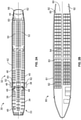
- FIG. 2A illustrates a top plan view of an internal cabin 30 of an aircraft, according to an example of the present disclosure.
- the internal cabin 30 may be within the fuselage 32 of the aircraft, such as the fuselage 18 of Figure 1 .
- one or more fuselage walls may define the internal cabin 30.
- the internal cabin 30 includes multiple sections, including a front section 33, a first class section 34, a business class section 36, a front galley 38, an expanded economy or coach section 40, a standard economy of coach section 42, and an aft section 44, which may include multiple lavatories and galleys.
- the internal cabin 30 may include more or less sections than shown.
- the internal cabin 30 may not include a first class section, and may include more or less galleys than shown.
- Each of the sections may be separated by a cabin transition area 46, which may include class divider assemblies between aisles 48.
- the internal cabin 30 includes two aisles 50 and 52 that lead to the aft section 44.
- the internal cabin 30 may have less or more aisles than shown.
- the internal cabin 30 may include a single aisle that extends through the center of the internal cabin 30 that leads to the aft section 44.
- the aisles 48, 50, and 52 extend to egress paths or door passageways 60. Exit doors 62 are located at ends of the egress paths 60.
- the egress paths 60 may be perpendicular to the aisles 48, 50, and 52.
- the internal cabin 30 may include more egress paths 60 at different locations than shown. As described herein, lavatory systems may be located at or proximate to intersections of the aisles 48, 50, 52 and the egress paths 60.
- FIG 2B illustrates a top plan view of an internal cabin 80 of an aircraft, according to an example of the present disclosure.
- the internal cabin 80 is an example of the internal cabin 30 shown in Figure 1 .
- the internal cabin 80 may be within a fuselage 81 of the aircraft.
- one or more fuselage walls may define the internal cabin 80.
- the internal cabin 80 includes multiple sections, including a main cabin 82 having passenger seats 83, and an aft section 85 behind the main cabin 82. It is to be understood that the internal cabin 80 may include more or less sections than shown.
- the internal cabin 80 may include a single aisle 84 that leads to the aft section 85.
- the single aisle 84 may extend through the center of the internal cabin 80 that leads to the aft section 85.
- the single aisle 84 may be coaxially aligned with a central longitudinal plane of the internal cabin 80.
- the aisle 84 extends to an egress path or door passageway 90. Exit doors 92 are located at ends of the egress path 90.
- the egress path 90 may be perpendicular to the aisle 84.
- the internal cabin 80 may include more egress paths than shown. As described herein, lavatory systems may be located at or proximate to intersections of the aisle 84 and one or more egress paths 90.
- FIG 3 illustrates a perspective interior view of an internal cabin 100 of an aircraft, according to an example of the present disclosure.
- the internal cabin 100 is an example of the internal cabin 30, shown in Figure 1 .
- the internal cabin 100 includes outboard walls 102 connected to a ceiling 104. Windows 106 may be formed within the outboard walls 102.
- a floor 108 supports rows of seats 110.
- a row 112 may include two seats 110 on either side of an aisle 113. However, the row 112 may include more or less seats 110 than shown. Additionally, the internal cabin 100 may include more aisles than shown.
- Passenger service units (PSUs) 114 are secured between an outboard wall 102 and the ceiling 104 on either side of the aisle 113.
- the PSUs 114 extend between a front end and rear end of the internal cabin 100.
- a PSU 114 may be positioned over each seat 110 within a row 112.
- Each PSU 114 may include a housing 116 that may contain vents, reading lights, an oxygen bag drop panel, an attendant request button, and/or other such controls over each seat 110 (or groups of seats) within a row 112.
- Overhead stowage bin assemblies 118 are secured to the ceiling 104 and/or the outboard wall 102 above and inboard from the PSU 114 on either side of the aisle 113.
- the overhead stowage bin assemblies 118 are secured over the seats 110.
- the overhead stowage bin assemblies 118 extend between the front and rear end of the internal cabin 100.
- Each stowage bin assembly 118 may include a pivot bin or bucket 120 pivotally secured to a strongback (hidden from view in Figure 3 ).
- the overhead stowage bin assemblies 118 may be positioned above and inboard from lower surfaces of the PSUs 114.
- the overhead stowage bin assemblies 118 are configured to be pivoted open in order to receive passenger carry-on baggage and personal items, for example.
- outboard means a position that is further away from a central longitudinal plane 122 of the internal cabin 100 as compared to another component.
- inboard means a position that is closer to the central longitudinal plane 122 of the internal cabin 100 as compared to another component.
- a lower surface of a PSU 114 may be outboard in relation to a stowage bin assembly 118.
- galley carts are stored in cart compartments within galleys, such as the galley 38.
- the galley carts are sized and shaped to be stored within the cart compartments, removed therefrom, and move within the aisles of the internal cabin, such as the aisle 113.
- at least one of the galley carts includes one or more UV light sources that are configured to emit UV light that sanitizes surfaces of components (such as seats, monuments, stowage bins, PSUs, floors, ceilings, and the like) within an internal cabin.
- FIG. 4 illustrate a lateral view of a galley cart 200, according to an example of the present disclosure.
- the galley cart 200 includes a base 202, end walls 204 extending upwardly from the base 202, lateral walls 206 extending upwardly from the base 202, and a counter or top wall 208 connected to the end walls 204 and the lateral walls 206 opposite from the base 202.
- An internal chamber 210 is defined between the base 202, the end walls 204, the lateral walls 206, and the top wall 208.
- Wheels 212 downwardly extend from the base 202.
- the galley cart 200 includes four wheels 212 proximate to four corners of the base 202.
- the wheels 212 are configured to be supported on a floor of an internal cabin and allow the galley cart 200 to be rolled to different locations within the internal cabin.
- FIG 5 illustrates a front view of the galley cart 200 of Figure 4 .
- An end wall 204 at the front of the galley cart 200 includes a main door 214 that is configured to be selectively opened and closed.
- the main door 214 includes a latch handle 216 proximate to a first lateral wall 204, and is pivotally coupled to a hinge 218 proximate to a second lateral wall 204 that is opposite from the first lateral wall 204.
- the main door 214 is configured to pivotally open and close about the hinge 218.
- the galley cart 200 can also include a handle 220 extending from a top portion, such as at one or both ends.
- FIG. 6 illustrates an internal view of the galley cart 200 through line 6-6 of Figure 5 .
- the internal chamber 210 of the galley cart 200 is typically configured to contain consumable items, such as beverages 222 (for example, soft drinks, cans of beer, bottles of liquor, and the like), water bottles 224, ice 226, coffee materials 228, prepared meals 230, snacks 232, and the like.
- a work surface 234, such as a counter or ledge, can extend within and/or from the internal chamber 210 proximate to the top wall 208.
- the galley cart 200 is sized and shaped to be contained or otherwise stored within a cart compartment within an internal cabin of a vehicle.
- the galley cart 200 is further sized and shaped to move into and through aisles of the internal cabin, such as the aisle 113 shown in Figure 3 , which is between rows of seats.
- the galley cart 200 can be a full size cart, a half size cart, or the like.
- the galley cart 200 includes one or more UV light sources that are configured to emit UV light to sanitize components within the internal cabin.
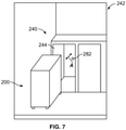
- FIG. 7 illustrates a perspective view of a galley 240 within an internal cabin 242, according to an example of the present disclosure.
- the galley 240 includes one or more cart compartments 244.
- a cart compartment 244 is configured to receive and retain the galley cart 200.
- the galley cart 200 is configured to be moved into and out of the cart compartment 244 in the direction of arrows A.
- Figure 8 illustrate a lateral view of the galley cart 200, according to an example of the present disclosure.
- the lateral walls 206 include transparent portions 250, such as panels, entire walls or sections thereof, and/or the like.
- the transparent portions 250 may be or include glass or plexiglass panels that form the lateral walls 206, or portions thereof.
- the transparent portions 250 allow UV light emitted from UV light sources inside the galley cart 200 to pass therethrough.
- the lateral walls 206 can include outer frames with open spaces therebetween.
- Figure 9 illustrates a front view of the galley cart 200 of Figure 8 .
- the end walls 204 include transparent portions 252, such as panels, entire walls or sections thereof, and/or the like.
- the transparent portions 252 may be or include glass or plexiglass panels that form the end walls 204, or portions thereof.
- the transparent portions 250 allow UV light emitted by UV light sources inside the galley cart 200 to pass therethrough.
- the end walls 204 can include outer frames with open spaces therebetween.
- FIG 10 illustrates an internal view of the galley cart 200 through line 10-10 of Figure 5 .
- one or more UV light sources 260 are secured within the internal chamber 210.
- the galley cart 200 does not contain consumable items. Instead, the galley cart 200 contains the UV light sources 260 and associated components, such as a power source 262 coupled to the UV light sources 260, and a controller 264 coupled to the UV light sources 260 (for example, one or more processors that are configured to control operation of the UV light sources 260). Because the UV light sources 260 are contained within the internal chamber 210, they are protected from being touched, bumped, inadvertently engaged, damaged, or the like from outside the galley cart 200.
- the UV light sources 260 are configured to emit UV light through the transparent portions 250 and 252 to sanitize surfaces of components within an internal cabin.
- the internal chamber 210 contains UV light sources 260 to emit UV light in a forward direction 266, a rearward direction 268, a first lateral direction 270, and a second lateral direction 272, which is opposite the first lateral direction. That is, the UV light sources 260 are configured to emit the UV light from inside the internal chamber 210 around the galley cart 200.
- the galley cart 200 can include UV light sources 260 that emit UV light in less than all of the forward direction 266, the rearward direction 268, the first lateral direction 270, and the second lateral direction 272.
- the galley cart 200 includes one or more UV light sources 260 proximate to the top wall 208 (such as within 5 inches of less), one or more UV light sources 260 proximate to junctions of one or both end walls 204 and one or both lateral walls 206 (such as within 5 inches or less), one or more UV light sources 260 proximate to the base 202, and/or the like.
- One or more light sources 260 can be at or proximate to a center of the galley cart 200.
- the galley cart 200 can include more or less UV light sources 260 than shown.
- the UV light sources 260 may be linear UV light arrays. As another option, one or more of the UV light sources 260 may be a spherical UV light source that emits UV light in all directions.
- the galley cart 200 includes a single spherical UV light source 260 within the internal chamber 210. The UV light source 260 can emit UV light in all directions.
- the top wall 208 and the base 202 can also include transparent portions.
- One or more UV light sources 260 can be configured to emit UV light through the top wall 208 and the base 202 to sanitize surfaces above and below the galley cart 200.
- the controller 264 and the UV light sources 260 can be powered through a main power system within the internal cabin 242.
- the galley cart 200 can include a plug 280 that is configured to dock with a reciprocal receptacle 282 (or vice versa) within the cart compartment 244 when the galley cart 200 is stored within the cart compartment 244.
- the plug 280 is connected to the receptacle 282 (which is connected to a power source)
- electrical energy is transferred to the power source 262, such as one or more batteries, thereby automatically charging or recharging the batteries.
- the power source 262 may be electrically connected to an electrical cord that includes a plug that is configured to removably couple to a reciprocal receptacle within the internal cabin.
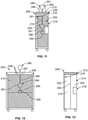
- FIG 11 illustrates a front view of the galley cart 200, according to an example of the present disclosure.
- Figure 12 illustrates a lateral view of the galley cart 200 of Figure 11 .
- a UV light source 260 may be or otherwise include a spherical UV lamp 261.
- the spherical UV lamp 261 can be fixed in position within the internal chamber 210 and configured to emit UV light in all radial directions.
- the UV light source 260 (whether the spherical UV lamp 261, a linear UV array, or the like) is coupled to a mount 290, such as a telescoping, articulating, pivoting, or the like arm(s) and/or beam(s), which, in turn is connected to an actuator 292, such as a motor.
- the actuator 292 is configured to move the UV light source 260 between a stowed position 294 within the internal chamber 210, and an extended position 296 outside of the internal chamber, such as the UV lamp 260 extending through an opening 297 within the top wall 208.
- a door 298 may be opened to expose the opening 297.
- the extended position is through one or more walls other than, and/or in addition to, the top wall 208.
- Figure 13 illustrates a front view of the galley cart 200, according to an example of the present disclosure.
- the internal chamber 210 may include a dividing wall 300 that separates the internal chamber 210 into a first compartment 302 and a second compartment 304.
- the first compartment 302 contains one or more UV light sources 260, as shown and described with respect to Figures 8-13 .
- the second compartment 304 is shielded from UV light by the dividing wall 300, and is configured to contains consumable items, as shown and described with respect to Figure 6 .
- Figure 14 illustrates a lateral view of the galley cart 200, according to an example of the present disclosure.
- Figure 15 illustrates a front view of the galley cart 200 of Figure 14 .
- one or more UV light sources 260 are secured to exterior surfaces of the one or more of the base 202, the end walls 204, the lateral walls 206, and/or the top wall 208.
- the galley cart 200 may or may not include transparent portions. More or less UV light sources 260 than shown may be used. Further, less than all of the base 202, the end walls 204, the lateral walls 206, and the top wall 208 may include UV light sources 260 on exterior surfaces thereof.
- FIG 16 illustrates a perspective view of a galley insert 320 in relation to an insert compartment 322 within a galley 324, according to an example of the present disclosure.
- the galley insert 320 includes a container 326 defining an internal chamber 328.
- the container 326 is configured to be stored within the insert compartment 322.
- the galley insert 320 includes one or more UV light sources 260.
- a spherical UV lamp 260 is within the internal chamber 328, and walls of the container 326 are transparent, thereby allowing UV light emitted by the UV lamp 260 to pass therethrough.
- one or more UV light sources 260 can be linear arrays, and/or secured to external surfaces of the container 326, which may or may not include transparent walls.
- the galley insert 320 When the galley insert 320 is in a stored position within the insert compartment 322, a latch 330 can be engaged to secure the galley insert 320 within insert compartment 322. Further, the galley insert 320 can include a plug 332 that mates with a reciprocal receptacle 334 within the insert compartment 322 so that a power source (for example, one or more batteries) of the galley insert 320 can be charged and re-charged.
- a power source for example, one or more batteries
- the galley insert 320 can be removed from the insert compartment 322 and placed in a position within the internal cabin to sanitize surfaces of components.
- the galley insert 320 can be positioned within a flight deck, seating area, lavatory, or the like within an internal cabin, and the UV light source 260 can be activated to emit light to sanitize various surfaces.
- the galley insert 320 may be positioned on the galley cart 200 (such as shown in Figures 4-15 ).
- Figure 17 illustrates an ultraviolet light spectrum.
- the UV light sources 260 are configured to emit sanitizing UV light within a far UV spectrum, such as between 200 nm to 230 nm.
- the UV light sources 260 emit sanitizing UV light having a wavelength of 222 nm.
- UVC light having a wavelength of 222 nm kills pathogens (such as viruses and bacteria), instead of inactivating pathogens.
- UVC light at a wavelength of 254 nm inactivates pathogens by interfering with their DNA, resulting in temporary inactivation, but may not kill the pathogens. Instead, the pathogen may be reactivated by exposure to ordinary white light at a reactivation rate of 10% per hour (or about 10% per hour).
- UVC light at a wavelength of 254 nm may be ineffective in illuminated areas, such as within an internal cabin of a vehicle.
- UVC light at 254 nm is not recommended for human exposure because it may be able to penetrate human cells.
- sanitizing UV light having a wavelength of 222 nm is safe for human exposure and kills pathogens. Further, the sanitizing UV light having a wavelength of 222 nm may be emitted at full power within one millisecond or less of a UV light source 260 being activated (in contrast the UVC light having a wavelength of 254 nm, which may take seconds or even minutes to reach full power).
- the UV light sources 260 may emit sanitizing UV light at wavelengths other than between 220-230 nm.
- the UV light sources 260 may emit sanitizing UV light between 230-280 nm, within the UVC spectrum.
- FIG 18 illustrates a perspective end view of a UV light source 260, according to an example of the present disclosure.
- the UV light source 260 shown in Figure 18 is merely exemplary.
- the UV light source 260 can be configured other than shown and described.
- the UV light source 260 includes a UV lamp 440 and a reflector 442.
- the UV lamp 440 and the reflector 442 can be secured within a shroud, for example.
- the reflector 442 is secured to an underside of the shroud, such as through one or more adhesives.
- the reflector 442 is an integral part of the shroud.
- the reflector 442 may be or otherwise provide the underside of the shroud.
- the reflector 442 provides a reflective surface 443 (such as formed of Teflon, a mirrored surface, and/or the like) that is configured to outwardly reflect UV light emitted by the UV lamp 440.
- shroud may be or include a shell formed of fiberglass, and the reflector 442 may be formed of Teflon that provides a 98% reflectivity.
- the reflector 442 may extend along an entire length of the underside of the shroud. Optionally, the reflector 442 may extend along less than an entire length of the underside of the shroud.
- the UV lamp 440 may extend along an entire length (or along substantially the entire length).
- the UV lamp 440 is secured to the reflector 442 and/or the shroud through one or more brackets, for example.
- the UV lamp 440 includes one or more UV light emitters, such as one more bulbs, light emitting elements (such as light emitting diodes), and/or the like.
- the UV lamp 440 is configured to emit UV light in the far UV spectrum, such as at a wavelength between 200 nm - 230 nm.
- the UV lamp 440 is configured to emit UV light having a wavelength of 222 nm.
- the UV lamp 440 may be or include a 300 W bulb that is configured to emit UV light having a wavelength of 222 nm.
- the reflector 442 includes flat, upright side walls 444 connected together through an upper curved wall 446.
- the upper curved wall 446 may be bowed outwardly away from the UV lamp 440.
- the upper curved wall 446 may have a parabolic cross-section and/or profile.
- the straight, linear side walls 444 provide desired reflection and/or focusing of UV light emitted from the UV lamp 440 toward and onto a desired location.
- the side walls 444 may not be linear and flat.
- FIG 19 illustrates a perspective end view of the UV light source 260, according to an example of the present disclosure.
- the UV light source 260 shown in Figure 19 is merely exemplary.
- the UV light source 260 can be configured other than shown and described.
- the reflector 442 shown in Figure 19 is similar to the reflector 442 shown in Figure 18 , except that the side walls 444 may outwardly cant from the upper curved wall 446.
- Figure 20 illustrates a perspective end view of the UV light source 260, according to an example of the present disclosure.
- the UV light source 260 shown in Figure 20 is merely exemplary.
- the UV light source 260 can be configured other than shown and described.
- the side walls 444 may be curved according to the curvature of the upper curved wall 446.
- examples of the present disclosure provide systems and a methods for efficiently sterilizing surfaces, components, structures, and/or the like within an internal cabin of a vehicle. Further, examples of the present disclosure provide compact, easy-to-use, and safe systems and methods for using UV light to sterilize surfaces within an internal cabin.
- a structure, limitation, or element that is "configured to” perform a task or operation is particularly structurally formed, constructed, or adapted in a manner corresponding to the task or operation.
- an object that is merely capable of being modified to perform the task or operation is not “configured to” perform the task or operation as used herein.
Landscapes
- Health & Medical Sciences (AREA)
- Engineering & Computer Science (AREA)
- Aviation & Aerospace Engineering (AREA)
- Veterinary Medicine (AREA)
- General Health & Medical Sciences (AREA)
- Public Health (AREA)
- Animal Behavior & Ethology (AREA)
- Life Sciences & Earth Sciences (AREA)
- Epidemiology (AREA)
- Manufacturing & Machinery (AREA)
- Transportation (AREA)
- Apparatus For Disinfection Or Sterilisation (AREA)
- Led Device Packages (AREA)
Abstract
Description
- Examples of the present disclosure generally relate to sanitizing systems, such as may be used to sanitize structures and areas within vehicles, such as commercial aircraft.
- Vehicles such as commercial aircraft are used to transport passengers between various locations. Systems are currently being developed to disinfect or otherwise sanitize surfaces within aircraft, for example, that use ultraviolet (UV) light. However, many known UV light sanitizing systems are typically large, bulky, and often require fixed, stationary infrastructure.
- A need exists for a system and a method for efficiently sterilizing surfaces within an internal cabin of a vehicle, such as a commercial aircraft.
- With that need in mind, certain examples of the present disclosure provide a galley cart for use within an internal cabin of a vehicle. The galley cart is configured to be stored within a cart compartment within a galley of the internal cabin. The galley cart includes one or more ultraviolet (UV) light sources configured to emit UV light onto one or more surfaces of one or more components within the internal cabin to sanitize the one or more surfaces.
- In at least one example, the galley cart includes a base, wheels extending downwardly from the base, end walls extending upwardly from the base, lateral walls extending upwardly from the base, and a top wall connected to the end walls and the lateral walls opposite from the base. An internal chamber is defined between the base, the end walls, the lateral walls, and the top wall.
- In at least one example, the one or more UV light sources are within the internal chamber. Further, one or more of the base, the end walls, the lateral walls, and the top panel can include one or more transparent portions that allow the UV light emitted by the one or more UV light sources to pass.
- In at least one example, the galley cart further includes a mount coupled to the one or more UV light sources, and an actuator operatively coupled to the mount. The actuator is configured to move the one or more UV light sources between a stowed position within the internal chamber and an extended position outside of the internal chamber.
- As another example, the one or more UV light sources are secured to one or more exterior surfaces of one or more of the base, the end walls, the lateral walls, or the top wall.
- In at least one example, the galley cart is not configured to contain consumable items.
- The galley cart can include a power source that is configured to provide power to the one or more UV light sources. The power source can include one or more batteries. The one or more batteries can be automatically recharged when the galley cart is stored in the cart compartment.
- The galley cart can include a controller configured to control operation of the one or more UV light sources.
- In at least one example, the galley cart includes a first compartment including the one or more UV light sources, and a second compartment configured to contain consumable items.
- In at least one example, a galley insert is removably contained within an insert compartment. The galley insert includes at least one UV light source.
- In at least one example, the one or more UV light sources are configured to emit the UV light at a wavelength of 222 nm.
- Certain examples of the present disclosure provide a method for sanitizing a surface of a component within an internal cabin of a vehicle. The method includes providing a galley cart that is configured to be stored within a cart compartment within a galley of the internal cabin with one or more or more ultraviolet (UV) light sources. In at least one example, the method also include emitting UV light from the one or more UV light sources onto the surface of the component.
- Certain examples of the present disclosure provide a vehicle including an internal cabin, a galley within the internal cabin, a cart compartment within the galley, and a galley cart configured to be stored within and removed from the cart compartment. The galley cart includes one or more ultraviolet (UV) light sources configured to emit UV light onto one or more surfaces of one or more components within the internal cabin to sanitize the one or more surfaces.
-
-
Figure 1 illustrates a perspective front view of an aircraft. -
Figure 2A illustrates a top plan view of an internal cabin of an aircraft. -
Figure 2B illustrates a top plan view of an internal cabin of an aircraft. -
Figure 3 illustrates a perspective interior view of an internal cabin of an aircraft. -
Figure 4 illustrate a lateral view of a galley cart. -
Figure 5 illustrates a front view of the galley cart ofFigure 4 . -
Figure 6 illustrates an internal view of the galley cart through line 6-6 ofFigure 5 . -
Figure 7 illustrates a perspective view of a galley within an internal cabin. -
Figure 8 illustrate a lateral view of a galley cart. -
Figure 9 illustrates a front view of the galley cart ofFigure 8 . -
Figure 10 illustrates an internal view of the galley cart through line 10-10 ofFigure 9 . -
Figure 11 illustrates a front view of a galley cart. -
Figure 12 illustrates a lateral view of the galley cart ofFigure 11 . -
Figure 13 illustrates a front view of a galley car. -
Figure 14 illustrates a lateral view of a galley cart. -
Figure 15 illustrates a front view of the galley cart ofFigure 14 . -
Figure 16 illustrates a perspective view of a galley insert in relation to an insert compartment within a galley. -
Figure 17 illustrates an ultraviolet light spectrum. -
Figure 18 illustrates a perspective end view of a UV light source. -
Figure 19 illustrates a perspective end view of a UV light source. -
Figure 20 illustrates a perspective end view of a UV light source. - The foregoing summary, as well as the following detailed description of certain examples will be better understood when read in conjunction with the appended drawings. As used herein, an element or step recited in the singular and preceded by the word "a" or "an" should be understood as not necessarily excluding the plural of the elements or steps. Further, references to "one example" are not intended to be interpreted as excluding the existence of additional examples that also incorporate the recited features. Moreover, unless explicitly stated to the contrary, examples "comprising" or "having" an element or a plurality of elements having a particular condition can include additional elements not having that condition.
- Certain examples of the present disclosure provide a sanitizing system and method that includes an ultraviolet (UV) lamp (such as an excimer lamp) that emits UV light in a far UV light spectrum, such as at a wavelength of 222 nm, which neutralizes (such as kills) microbes (for example, viruses and bacteria), while posing no risk to humans. The UV lamp may be used within an internal cabin to decontaminate and kill pathogens. The UV lamp may be coupled to a galley cart that is configured for use within in a vehicle, such as a commercial aircraft
- Certain examples of the present disclosure provide a galley cart configured for use within an internal cabin of a vehicle. The galley cart includes one or more UV light sources that are configured to emit UV light onto surfaces of components within the internal cabin to sanitize the surfaces.
- By utilizing a frame of existing galley carts to include UV lighting systems, examples of the present disclosure provide portable sanitization systems that can be stored onboard a vehicle (such as a commercial aircraft), and moved throughout the internal cabin, such as between flights, during maintenance, and/or when the vehicle is in storage. The galley carts can be half carts, full carts, etc. Because the galley carts are already sized and shaped to be used and stored within internal cabins, they are easily used with existing vehicles, such as commercial aircraft. That is, there may be no need to provide separate and/or customized storage locations for the galley carts.
- Certain examples of the present disclosure provide a galley cart for use within an internal cabin of a vehicle, such as a commercial aircraft. The galley cart includes one or more UV light sources, a power supply (such as one or more batteries), a controller, and at least one transparent wall. In at least one example, UV light from the UV light sources is emitted from all sides. In at least example, the galley cart has a first compartment for UV light disinfection, and a second compartment for storage of food, snacks, and/or beverages. In at least one example, the galley cart has a separate removeable self-contained UV light source.
- The galley cart is configured to be stowed in a standard galley cart stowage compartment in an aircraft. The galley cart can be automatically charged when stowed.
- The galley cart can include an extending arm that allows a UV light source to be extended beyond the interior of the galley cart. The extended arm can include a UV light emitting sphere, which allows the light to be emitted in all directions.
- The galley cart can be stowed just like any other galley cart. An attendant can move the cart to a location that needs disinfecting. In at least one example, the UV light source(s) emit UV light at a wavelength of 222 nm, which is safe for use around humans, and therefore can be operated in the presence of individuals.
- In at least one example, a self-contained UV light source can be contained in a galley insert, such as a container that locks into a specific location in a galley within an internal cabin. The insert sides can be transparent to allow the UV light to disperse from the container. Batteries can be charged while the insert is located in a cart compartment. Such charging can be accomplished via a blind mate power connect that is attached when the galley insert is pushed in and disconnects when the insert is removed. The galley insert can be removed from the cart compartment and placed where UV light disinfection is needed.
- As described herein, certain examples of the present disclosure provide a method for sanitizing a surface of a component within an internal cabin of a vehicle. The method includes providing a galley cart that is configured to be stored within a cart compartment within a galley of the internal cabin with one or more or more ultraviolet (UV) light sources. The method further includes emitting UV light from the UV light sources onto the surface.
-
Figure 1 illustrates a perspective front view of anaircraft 10, according to an example of the present disclosure. Theaircraft 10 includes apropulsion system 12 that includesengines 14, for example. Optionally, thepropulsion system 12 may includemore engines 14 than shown. Theengines 14 are carried bywings 16 of theaircraft 10. In other examples, theengines 14 may be carried by afuselage 18 and/or anempennage 20. Theempennage 20 may also supporthorizontal stabilizers 22 and avertical stabilizer 24. - The
fuselage 18 of theaircraft 10 defines aninternal cabin 30, which includes a flight deck or cockpit, one or more work sections (for example, galleys, personnel carry-on baggage areas, and the like), one or more passenger sections (for example, first class, business class, and coach sections), one or more lavatories, and/or the like. Theinternal cabin 30 includes one or more lavatory systems, lavatory units, or lavatories, as described herein. - Alternatively, instead of an aircraft, examples of the present disclosure may be used with various other vehicles, such as automobiles, buses, locomotives and train cars, watercraft, spacecraft, and the like. Further, examples of the present disclosure may be used with respect to fixed structures, such as commercial and residential buildings.
-
Figure 2A illustrates a top plan view of aninternal cabin 30 of an aircraft, according to an example of the present disclosure. Theinternal cabin 30 may be within thefuselage 32 of the aircraft, such as thefuselage 18 ofFigure 1 . For example, one or more fuselage walls may define theinternal cabin 30. Theinternal cabin 30 includes multiple sections, including afront section 33, afirst class section 34, abusiness class section 36, afront galley 38, an expanded economy orcoach section 40, a standard economy ofcoach section 42, and anaft section 44, which may include multiple lavatories and galleys. It is to be understood that theinternal cabin 30 may include more or less sections than shown. For example, theinternal cabin 30 may not include a first class section, and may include more or less galleys than shown. Each of the sections may be separated by acabin transition area 46, which may include class divider assemblies betweenaisles 48. - As shown in
Figure 2A , theinternal cabin 30 includes twoaisles aft section 44. Optionally, theinternal cabin 30 may have less or more aisles than shown. For example, theinternal cabin 30 may include a single aisle that extends through the center of theinternal cabin 30 that leads to theaft section 44. - The
aisles door passageways 60.Exit doors 62 are located at ends of theegress paths 60. Theegress paths 60 may be perpendicular to theaisles internal cabin 30 may includemore egress paths 60 at different locations than shown. As described herein, lavatory systems may be located at or proximate to intersections of theaisles egress paths 60. -
Figure 2B illustrates a top plan view of aninternal cabin 80 of an aircraft, according to an example of the present disclosure. Theinternal cabin 80 is an example of theinternal cabin 30 shown inFigure 1 . Theinternal cabin 80 may be within afuselage 81 of the aircraft. For example, one or more fuselage walls may define theinternal cabin 80. Theinternal cabin 80 includes multiple sections, including amain cabin 82 havingpassenger seats 83, and anaft section 85 behind themain cabin 82. It is to be understood that theinternal cabin 80 may include more or less sections than shown. - The
internal cabin 80 may include asingle aisle 84 that leads to theaft section 85. Thesingle aisle 84 may extend through the center of theinternal cabin 80 that leads to theaft section 85. For example, thesingle aisle 84 may be coaxially aligned with a central longitudinal plane of theinternal cabin 80. - The
aisle 84 extends to an egress path ordoor passageway 90.Exit doors 92 are located at ends of theegress path 90. Theegress path 90 may be perpendicular to theaisle 84. Theinternal cabin 80 may include more egress paths than shown. As described herein, lavatory systems may be located at or proximate to intersections of theaisle 84 and one ormore egress paths 90. -
Figure 3 illustrates a perspective interior view of aninternal cabin 100 of an aircraft, according to an example of the present disclosure. Theinternal cabin 100 is an example of theinternal cabin 30, shown inFigure 1 . Theinternal cabin 100 includesoutboard walls 102 connected to aceiling 104.Windows 106 may be formed within theoutboard walls 102. Afloor 108 supports rows ofseats 110. As shown inFigure 3 , arow 112 may include twoseats 110 on either side of anaisle 113. However, therow 112 may include more orless seats 110 than shown. Additionally, theinternal cabin 100 may include more aisles than shown. - Passenger service units (PSUs) 114 are secured between an
outboard wall 102 and theceiling 104 on either side of theaisle 113. ThePSUs 114 extend between a front end and rear end of theinternal cabin 100. For example, aPSU 114 may be positioned over eachseat 110 within arow 112. EachPSU 114 may include ahousing 116 that may contain vents, reading lights, an oxygen bag drop panel, an attendant request button, and/or other such controls over each seat 110 (or groups of seats) within arow 112. - Overhead
stowage bin assemblies 118 are secured to theceiling 104 and/or theoutboard wall 102 above and inboard from thePSU 114 on either side of theaisle 113. The overheadstowage bin assemblies 118 are secured over theseats 110. The overheadstowage bin assemblies 118 extend between the front and rear end of theinternal cabin 100. Eachstowage bin assembly 118 may include a pivot bin orbucket 120 pivotally secured to a strongback (hidden from view inFigure 3 ). The overheadstowage bin assemblies 118 may be positioned above and inboard from lower surfaces of thePSUs 114. The overheadstowage bin assemblies 118 are configured to be pivoted open in order to receive passenger carry-on baggage and personal items, for example. - As used herein, the term "outboard" means a position that is further away from a central
longitudinal plane 122 of theinternal cabin 100 as compared to another component. The term "inboard" means a position that is closer to the centrallongitudinal plane 122 of theinternal cabin 100 as compared to another component. For example, a lower surface of aPSU 114 may be outboard in relation to astowage bin assembly 118. - Referring to
Figures 1-3 , galley carts are stored in cart compartments within galleys, such as thegalley 38. The galley carts are sized and shaped to be stored within the cart compartments, removed therefrom, and move within the aisles of the internal cabin, such as theaisle 113. As described herein, at least one of the galley carts includes one or more UV light sources that are configured to emit UV light that sanitizes surfaces of components (such as seats, monuments, stowage bins, PSUs, floors, ceilings, and the like) within an internal cabin. -
Figure 4 illustrate a lateral view of agalley cart 200, according to an example of the present disclosure. Thegalley cart 200 includes abase 202, endwalls 204 extending upwardly from thebase 202,lateral walls 206 extending upwardly from thebase 202, and a counter ortop wall 208 connected to theend walls 204 and thelateral walls 206 opposite from thebase 202. Aninternal chamber 210 is defined between the base 202, theend walls 204, thelateral walls 206, and thetop wall 208.Wheels 212 downwardly extend from thebase 202. For example, thegalley cart 200 includes fourwheels 212 proximate to four corners of thebase 202. Thewheels 212 are configured to be supported on a floor of an internal cabin and allow thegalley cart 200 to be rolled to different locations within the internal cabin. -
Figure 5 illustrates a front view of thegalley cart 200 ofFigure 4 . Anend wall 204 at the front of thegalley cart 200 includes amain door 214 that is configured to be selectively opened and closed. Themain door 214 includes alatch handle 216 proximate to a firstlateral wall 204, and is pivotally coupled to ahinge 218 proximate to a secondlateral wall 204 that is opposite from the firstlateral wall 204. Themain door 214 is configured to pivotally open and close about thehinge 218. Thegalley cart 200 can also include ahandle 220 extending from a top portion, such as at one or both ends. -
Figure 6 illustrates an internal view of thegalley cart 200 through line 6-6 ofFigure 5 . Theinternal chamber 210 of thegalley cart 200 is typically configured to contain consumable items, such as beverages 222 (for example, soft drinks, cans of beer, bottles of liquor, and the like),water bottles 224,ice 226,coffee materials 228,prepared meals 230,snacks 232, and the like. Further, awork surface 234, such as a counter or ledge, can extend within and/or from theinternal chamber 210 proximate to thetop wall 208. - Referring to
Figures 4-6 , thegalley cart 200 is sized and shaped to be contained or otherwise stored within a cart compartment within an internal cabin of a vehicle. Thegalley cart 200 is further sized and shaped to move into and through aisles of the internal cabin, such as theaisle 113 shown inFigure 3 , which is between rows of seats. Thegalley cart 200 can be a full size cart, a half size cart, or the like. As described herein, thegalley cart 200 includes one or more UV light sources that are configured to emit UV light to sanitize components within the internal cabin. -
Figure 7 illustrates a perspective view of agalley 240 within aninternal cabin 242, according to an example of the present disclosure. Thegalley 240 includes one or more cart compartments 244. Acart compartment 244 is configured to receive and retain thegalley cart 200. For example, thegalley cart 200 is configured to be moved into and out of thecart compartment 244 in the direction of arrows A. -
Figure 8 illustrate a lateral view of thegalley cart 200, according to an example of the present disclosure. One or both of thelateral walls 206 includetransparent portions 250, such as panels, entire walls or sections thereof, and/or the like. For example, thetransparent portions 250 may be or include glass or plexiglass panels that form thelateral walls 206, or portions thereof. Thetransparent portions 250 allow UV light emitted from UV light sources inside thegalley cart 200 to pass therethrough. Optionally, instead of thetransparent portions 250, thelateral walls 206 can include outer frames with open spaces therebetween. -
Figure 9 illustrates a front view of thegalley cart 200 ofFigure 8 . One or both of theend walls 204 includetransparent portions 252, such as panels, entire walls or sections thereof, and/or the like. For example, thetransparent portions 252 may be or include glass or plexiglass panels that form theend walls 204, or portions thereof. Thetransparent portions 250 allow UV light emitted by UV light sources inside thegalley cart 200 to pass therethrough. Optionally, instead of thetransparent portions 250, theend walls 204 can include outer frames with open spaces therebetween. -
Figure 10 illustrates an internal view of thegalley cart 200 through line 10-10 ofFigure 5 . As shown, one or more UVlight sources 260 are secured within theinternal chamber 210. In at least one example, thegalley cart 200 does not contain consumable items. Instead, thegalley cart 200 contains theUV light sources 260 and associated components, such as apower source 262 coupled to theUV light sources 260, and acontroller 264 coupled to the UV light sources 260 (for example, one or more processors that are configured to control operation of the UV light sources 260). Because theUV light sources 260 are contained within theinternal chamber 210, they are protected from being touched, bumped, inadvertently engaged, damaged, or the like from outside thegalley cart 200. - Referring to
Figures 8-10 , theUV light sources 260 are configured to emit UV light through thetransparent portions internal chamber 210 containsUV light sources 260 to emit UV light in aforward direction 266, arearward direction 268, a firstlateral direction 270, and a secondlateral direction 272, which is opposite the first lateral direction. That is, theUV light sources 260 are configured to emit the UV light from inside theinternal chamber 210 around thegalley cart 200. Optionally, thegalley cart 200 can include UVlight sources 260 that emit UV light in less than all of theforward direction 266, therearward direction 268, the firstlateral direction 270, and the secondlateral direction 272. - In at least one example, the
galley cart 200 includes one or more UVlight sources 260 proximate to the top wall 208 (such as within 5 inches of less), one or more UVlight sources 260 proximate to junctions of one or bothend walls 204 and one or both lateral walls 206 (such as within 5 inches or less), one or more UVlight sources 260 proximate to thebase 202, and/or the like. One or morelight sources 260 can be at or proximate to a center of thegalley cart 200. Thegalley cart 200 can include more or less UVlight sources 260 than shown. - As shown, the
UV light sources 260 may be linear UV light arrays. As another option, one or more of theUV light sources 260 may be a spherical UV light source that emits UV light in all directions. For example, in at least one example, thegalley cart 200 includes a single spherical UVlight source 260 within theinternal chamber 210. The UVlight source 260 can emit UV light in all directions. - In at least one example, the
top wall 208 and the base 202 can also include transparent portions. One or more UVlight sources 260 can be configured to emit UV light through thetop wall 208 and the base 202 to sanitize surfaces above and below thegalley cart 200. - Referring to
Figures 7-10 , thecontroller 264 and the UVlight sources 260 can be powered through a main power system within theinternal cabin 242. For example, thegalley cart 200 can include aplug 280 that is configured to dock with a reciprocal receptacle 282 (or vice versa) within thecart compartment 244 when thegalley cart 200 is stored within thecart compartment 244. When theplug 280 is connected to the receptacle 282 (which is connected to a power source), electrical energy is transferred to thepower source 262, such as one or more batteries, thereby automatically charging or recharging the batteries. In at least one other example, thepower source 262 may be electrically connected to an electrical cord that includes a plug that is configured to removably couple to a reciprocal receptacle within the internal cabin. -
Figure 11 illustrates a front view of thegalley cart 200, according to an example of the present disclosure.Figure 12 illustrates a lateral view of thegalley cart 200 ofFigure 11 . Referring toFigures 11 and 12 , in this example, aUV light source 260 may be or otherwise include aspherical UV lamp 261. Thespherical UV lamp 261 can be fixed in position within theinternal chamber 210 and configured to emit UV light in all radial directions. - In at least one other example, the UV light source 260 (whether the
spherical UV lamp 261, a linear UV array, or the like) is coupled to amount 290, such as a telescoping, articulating, pivoting, or the like arm(s) and/or beam(s), which, in turn is connected to anactuator 292, such as a motor. Theactuator 292 is configured to move theUV light source 260 between a stowedposition 294 within theinternal chamber 210, and anextended position 296 outside of the internal chamber, such as theUV lamp 260 extending through anopening 297 within thetop wall 208. For example, adoor 298 may be opened to expose theopening 297. In at least one other example, the extended position is through one or more walls other than, and/or in addition to, thetop wall 208. -
Figure 13 illustrates a front view of thegalley cart 200, according to an example of the present disclosure. In this example, theinternal chamber 210 may include a dividingwall 300 that separates theinternal chamber 210 into afirst compartment 302 and asecond compartment 304. Thefirst compartment 302 contains one or more UVlight sources 260, as shown and described with respect toFigures 8-13 . Thesecond compartment 304 is shielded from UV light by the dividingwall 300, and is configured to contains consumable items, as shown and described with respect toFigure 6 . -
Figure 14 illustrates a lateral view of thegalley cart 200, according to an example of the present disclosure.Figure 15 illustrates a front view of thegalley cart 200 ofFigure 14 . Referring toFigures 14 and 15 , in this example, one or more UVlight sources 260 are secured to exterior surfaces of the one or more of thebase 202, theend walls 204, thelateral walls 206, and/or thetop wall 208. Thegalley cart 200 may or may not include transparent portions. More or less UVlight sources 260 than shown may be used. Further, less than all of thebase 202, theend walls 204, thelateral walls 206, and thetop wall 208 may include UVlight sources 260 on exterior surfaces thereof. -
Figure 16 illustrates a perspective view of agalley insert 320 in relation to aninsert compartment 322 within agalley 324, according to an example of the present disclosure. Thegalley insert 320 includes acontainer 326 defining aninternal chamber 328. Thecontainer 326 is configured to be stored within theinsert compartment 322. In at least one example, thegalley insert 320 includes one or more UVlight sources 260. For example, aspherical UV lamp 260 is within theinternal chamber 328, and walls of thecontainer 326 are transparent, thereby allowing UV light emitted by theUV lamp 260 to pass therethrough. Optionally, one or more UVlight sources 260 can be linear arrays, and/or secured to external surfaces of thecontainer 326, which may or may not include transparent walls. - When the
galley insert 320 is in a stored position within theinsert compartment 322, alatch 330 can be engaged to secure thegalley insert 320 withininsert compartment 322. Further, thegalley insert 320 can include aplug 332 that mates with areciprocal receptacle 334 within theinsert compartment 322 so that a power source (for example, one or more batteries) of thegalley insert 320 can be charged and re-charged. - The
galley insert 320 can be removed from theinsert compartment 322 and placed in a position within the internal cabin to sanitize surfaces of components. For example, thegalley insert 320 can be positioned within a flight deck, seating area, lavatory, or the like within an internal cabin, and the UVlight source 260 can be activated to emit light to sanitize various surfaces. Further, thegalley insert 320 may be positioned on the galley cart 200 (such as shown inFigures 4-15 ). -
Figure 17 illustrates an ultraviolet light spectrum. Referring toFigures 4-17 , in at least one example, theUV light sources 260 are configured to emit sanitizing UV light within a far UV spectrum, such as between 200 nm to 230 nm. In at least one example, theUV light sources 260 emit sanitizing UV light having a wavelength of 222 nm. - It has been found that sanitizing UV light having a wavelength of 222 nm kills pathogens (such as viruses and bacteria), instead of inactivating pathogens. In contrast, UVC light at a wavelength of 254 nm inactivates pathogens by interfering with their DNA, resulting in temporary inactivation, but may not kill the pathogens. Instead, the pathogen may be reactivated by exposure to ordinary white light at a reactivation rate of 10% per hour (or about 10% per hour). As such, UVC light at a wavelength of 254 nm may be ineffective in illuminated areas, such as within an internal cabin of a vehicle. Moreover, UVC light at 254 nm is not recommended for human exposure because it may be able to penetrate human cells.
- In contrast, sanitizing UV light having a wavelength of 222 nm is safe for human exposure and kills pathogens. Further, the sanitizing UV light having a wavelength of 222 nm may be emitted at full power within one millisecond or less of a
UV light source 260 being activated (in contrast the UVC light having a wavelength of 254 nm, which may take seconds or even minutes to reach full power). - Alternatively, the
UV light sources 260 may emit sanitizing UV light at wavelengths other than between 220-230 nm. For example, theUV light sources 260 may emit sanitizing UV light between 230-280 nm, within the UVC spectrum. -
Figure 18 illustrates a perspective end view of aUV light source 260, according to an example of the present disclosure. The UVlight source 260 shown inFigure 18 is merely exemplary. The UVlight source 260 can be configured other than shown and described. - In at least one example, the UV
light source 260 includes aUV lamp 440 and areflector 442. TheUV lamp 440 and thereflector 442 can be secured within a shroud, for example. In at least one example, thereflector 442 is secured to an underside of the shroud, such as through one or more adhesives. In at last one other example, thereflector 442 is an integral part of the shroud. For example, thereflector 442 may be or otherwise provide the underside of the shroud. Thereflector 442 provides a reflective surface 443 (such as formed of Teflon, a mirrored surface, and/or the like) that is configured to outwardly reflect UV light emitted by theUV lamp 440. In at least one example, shroud may be or include a shell formed of fiberglass, and thereflector 442 may be formed of Teflon that provides a 98% reflectivity. - The
reflector 442 may extend along an entire length of the underside of the shroud. Optionally, thereflector 442 may extend along less than an entire length of the underside of the shroud. - The
UV lamp 440 may extend along an entire length (or along substantially the entire length). TheUV lamp 440 is secured to thereflector 442 and/or the shroud through one or more brackets, for example. TheUV lamp 440 includes one or more UV light emitters, such as one more bulbs, light emitting elements (such as light emitting diodes), and/or the like. In at least one example, theUV lamp 440 is configured to emit UV light in the far UV spectrum, such as at a wavelength between 200 nm - 230 nm. In at least one example, theUV lamp 440 is configured to emit UV light having a wavelength of 222 nm. For example, theUV lamp 440 may be or include a 300 W bulb that is configured to emit UV light having a wavelength of 222 nm. - As shown, the
reflector 442 includes flat,upright side walls 444 connected together through an uppercurved wall 446. The uppercurved wall 446 may be bowed outwardly away from theUV lamp 440. For example, the uppercurved wall 446 may have a parabolic cross-section and/or profile. - It has been found that the straight,
linear side walls 444 provide desired reflection and/or focusing of UV light emitted from theUV lamp 440 toward and onto a desired location. Alternatively, theside walls 444 may not be linear and flat. -
Figure 19 illustrates a perspective end view of the UVlight source 260, according to an example of the present disclosure. The UVlight source 260 shown inFigure 19 is merely exemplary. The UVlight source 260 can be configured other than shown and described. Thereflector 442 shown inFigure 19 is similar to thereflector 442 shown inFigure 18 , except that theside walls 444 may outwardly cant from the uppercurved wall 446. -
Figure 20 illustrates a perspective end view of the UVlight source 260, according to an example of the present disclosure. The UVlight source 260 shown inFigure 20 is merely exemplary. The UVlight source 260 can be configured other than shown and described. In this and other examples, theside walls 444 may be curved according to the curvature of the uppercurved wall 446. - As described herein, examples of the present disclosure provide systems and a methods for efficiently sterilizing surfaces, components, structures, and/or the like within an internal cabin of a vehicle. Further, examples of the present disclosure provide compact, easy-to-use, and safe systems and methods for using UV light to sterilize surfaces within an internal cabin.
- While various spatial and directional terms, such as top, bottom, lower, mid, lateral, horizontal, vertical, front and the like can be used to describe examples of the present disclosure, it is understood that such terms are merely used with respect to the orientations shown in the drawings. The orientations can be inverted, rotated, or otherwise changed, such that an upper portion is a lower portion, and vice versa, horizontal becomes vertical, and the like.
- As used herein, a structure, limitation, or element that is "configured to" perform a task or operation is particularly structurally formed, constructed, or adapted in a manner corresponding to the task or operation. For purposes of clarity and the avoidance of doubt, an object that is merely capable of being modified to perform the task or operation is not "configured to" perform the task or operation as used herein.
- It is to be understood that the above description is intended to be illustrative, and not restrictive. For example, the above-described examples (and/or features thereof) can be used in combination with each other. In addition, many modifications can be made to adapt a particular situation or material to the teachings of the various examples of the disclosure. While the dimensions and types of materials described herein are intended to define the parameters of the various examples of the disclosure, the examples are by no means limiting. Many other examples will be apparent to those of skill in the art upon reviewing the above description. In the appended claims and the detailed description herein, the terms "including" and "in which" are used as the plain-English equivalents of the respective terms "comprising" and "wherein." Moreover, the terms "first," "second," and "third," etc. are used merely as labels, and are not intended to impose numerical requirements on their objects.
- Clause 1. A galley cart for use within an internal cabin of a vehicle, wherein the galley cart is configured to be stored within a cart compartment within a galley of the internal cabin, the galley cart comprising one or more ultraviolet (UV) light sources configured to emit UV light onto one or more surfaces of one or more components within the internal cabin to sanitize the one or more surfaces.
- Clause 2. The galley cart of Clause 1, wherein the galley cart comprises a base; wheels extending downwardly from the base; end walls extending upwardly from the base; lateral walls extending upwardly from the base; and a top wall connected to the end walls and the lateral walls opposite from the base, wherein an internal chamber is defined between the base, the end walls, the lateral walls, and the top wall.
- Clause 3. The galley cart of Clause 2, wherein the one or more UV light sources are within the internal chamber.
- Clause 4. The galley cart of Clause 3, wherein one or more of the base, the end walls, the lateral walls, and the top wall include one or more transparent portions that allow the UV light emitted by the one or more UV light sources to pass.
- Clause 5. The galley cart of any of Clauses 2-4, further comprising a mount coupled to the one or more UV light sources; and an actuator operatively coupled to the mount, wherein the actuator is configured to move the one or more UV light sources between a stowed position within the internal chamber and an extended position outside of the internal chamber.
-
Clause 6. The galley cart of any of Clauses 2-5, wherein the one or more UV light sources are secured to one or more exterior surfaces of one or more of the base, the end walls, the lateral walls, or the top wall. - Clause 7. The galley cart of any of Clauses 1-6, wherein the galley cart is not configured to contain consumable items.
- Clause 8. The galley cart of any of Clauses 1-7, further comprising a power source that is configured to provide power to the one or more UV light sources.
- Clause 9. The galley cart of Clause 8, wherein the power source comprises one or more batteries.
-
Clause 10. The galley cart of Clause 9, wherein the one or more batteries are automatically recharged when the galley cart is stored in the cart compartment. - Clause 11. The galley cart of any of Clauses 1-10, further comprising a controller configured to control operation of the one or more UV light sources.
-
Clause 12. The galley cart of any of Clauses 1-11, further comprising a first compartment including the one or more UV light sources; and a second compartment configured to contain consumable items. - Clause 13. The galley cart of any of Clauses 1-12, further comprising a galley insert removably contained within an insert compartment, wherein the galley insert comprises the one or more UV light sources.
-
Clause 14. The galley cart of any of Clauses 1-13, wherein the one or more UV light sources are configured to emit the UV light at a wavelength of 222 nm. - Clause 15. A method for sanitizing a surface of a component within an internal cabin of a vehicle, the method comprising providing a galley cart that is configured to be stored within a cart compartment within a galley of the internal cabin with one or more or more ultraviolet (UV) light sources.
-
Clause 16. The method of Clause 15, further comprising emitting UV light from the one or more UV light sources onto the surface of the component. - Clause 17. A vehicle comprising an internal cabin; a galley within the internal cabin; a cart compartment within the galley; and a galley cart configured to be stored within and removed from the cart compartment, the galley cart comprising one or more ultraviolet (UV) light sources configured to emit UV light onto one or more surfaces of one or more components within the internal cabin to sanitize the one or more surfaces.
-
Clause 18. The vehicle of Clause 17, wherein the galley cart comprises a base; wheels extending downwardly from the base; end walls extending upwardly from the base; lateral walls extending upwardly from the base; and a top wall connected to the end walls and the lateral walls opposite from the base, wherein an internal chamber is defined between the base, the end walls, the lateral walls, and the top wall. - Clause 19. The vehicle of
Clause 18, wherein the one or more UV light sources are within the internal chamber. -
Clause 20. The vehicle of Clause 19 wherein one or more of the base, the end walls, the lateral walls, and the top wall include one or more transparent portions that allow the UV light emitted by the one or more UV light sources to pass. - Clause 21. A galley cart for use within an internal cabin of a vehicle, the galley cart comprising one or more ultraviolet (UV) light sources configured to emit UV light to sanitize one or more surfaces.
-
Clause 22. The galley cart of Clause 21, wherein the galley cart comprises a base; wheels extending downwardly from the base; end walls extending upwardly from the base; lateral walls extending upwardly from the base; a top wall connected to the end walls and the lateral walls opposite from the base; and an internal chamber defined between the base, the end walls, the lateral walls, and the top wall. - Clause 23. The galley cart of
Clause 22, wherein the one or more UV light sources are within the internal chamber. -
Clause 24. The galley cart of Clause 23, wherein one or more of the base, the end walls, the lateral walls, and the top wall include one or more transparent portions that allow the UV light emitted by the one or more UV light sources to pass. - Clause 25. The galley cart of any of Clauses 22-24, further comprising a mount coupled to the one or more UV light sources; and an actuator operatively coupled to the mount, wherein the actuator is configured to move the one or more UV light sources between a stowed position within the internal chamber and an extended position outside of the internal chamber.
- Clause 26. The galley cart of any of Clauses 22-25, wherein the one or more UV light sources are secured to one or more exterior surfaces of one or more of the base, the end walls, the lateral walls, or the top wall.
- Clause 27. The galley cart of any of Clauses 21-26, wherein the galley cart is not configured to contain consumable items.
- Clause 28. The galley cart of any of Clauses 21-27, further comprising a power source that is configured to provide power to the one or more UV light sources.
- Clause 29. The galley cart of Clause 8, wherein the power source comprises one or more batteries.
-
Clause 30. The galley cart of Clause 29, wherein the one or more batteries are automatically recharged when the galley cart is stored in the cart compartment. - Clause 31. The galley cart of any of Clauses 21-30, further comprising a controller configured to control operation of the one or more UV light sources.
-
Clause 32. The galley cart of any of Clauses 21-31, further comprising a first compartment including the one or more UV light sources; and a second compartment configured to contain consumable items. -
Clause 33. The galley cart of any of Clauses 21-32, further comprising a galley insert removably contained within an insert compartment, wherein the galley insert comprises the one or more UV light sources. -
Clause 34. The galley cart of any of Clauses 21-33, wherein the one or more UV light sources are configured to emit the UV light at a wavelength of 222 nm. - Clause 35. A vehicle comprising an internal cabin; a galley within the internal cabin; a cart compartment within the galley; and the galley cart of any of Clauses 21-34, wherein the galley cart is configured to be stored within and removed from the cart compartment.
-
Clause 36. A vehicle comprising an internal cabin; a galley within the internal cabin; a cart compartment within the galley; and a galley cart configured to be stored within and removed from the cart compartment, the galley cart comprising one or more ultraviolet (UV) light sources configured to emit UV light onto one or more surfaces of one or more components within the internal cabin to sanitize the one or more surfaces. - Clause 37. The vehicle of
Clause 36, wherein the galley cart comprises a base; wheels extending downwardly from the base; end walls extending upwardly from the base; lateral walls extending upwardly from the base; and a top wall connected to the end walls and the lateral walls opposite from the base, wherein an internal chamber is defined between the base, the end walls, the lateral walls, and the top wall. -
Clause 38. The vehicle of Clause 37, wherein the one or more UV light sources are within the internal chamber. - Clause 39. The vehicle of
Clause 38, wherein one or more of the base, the end walls, the lateral walls, and the top wall include one or more transparent portions that allow the UV light emitted by the one or more UV light sources to pass. -
Clause 40. The vehicle of any of Clauses 37-39, wherein the galley cart further comprises a mount coupled to the one or more UV light sources; and an actuator operatively coupled to the mount, wherein the actuator is configured to move the one or more UV light sources between a stowed position within the internal chamber and an extended position outside of the internal chamber. - Clause 41. The vehicle of any of Clauses 37-40, wherein the one or more UV light sources are secured to one or more exterior surfaces of one or more of the base, the end walls, the lateral walls, or the top wall.
-
Clause 42. The vehicle of any of Clauses 36-41, wherein the galley cart is not configured to contain consumable items. - Clause 43. The vehicle of any of Clauses 36-42, wherein the galley cart further comprises a power source that is configured to provide power to the one or more UV light sources.
-
Clause 44. The vehicle of Clause 43, wherein the power source comprises one or more batteries. - Clause 45. The vehicle of
Clause 44, wherein the one or more batteries are automatically recharged when the galley cart is stored in the cart compartment. -
Clause 46. The vehicle of any of Clauses 36-45, wherein the galley cart further comprises a controller configured to control operation of the one or more UV light sources. - Clause 47. The vehicle of any of Clauses 36-46, wherein the galley cart further comprises a first compartment including the one or more UV light sources; and a second compartment configured to contain consumable items.
-
Clause 48. The vehicle of any of Clauses 36-47, wherein the galley cart further comprises a galley insert removably contained within an insert compartment, wherein the galley insert comprises the one or more UV light sources. - Clause 49. The vehicle of any of Clauses 36-48, wherein the one or more UV light sources are configured to emit the UV light at a wavelength of 222 nm.
-
Clause 50. The vehicle of any of Clauses 36-49, wherein the vehicle is an aircraft. - This written description uses examples to disclose the various examples of the disclosure, including the best mode, and also to enable any person skilled in the art to practice the various examples of the disclosure, including making and using any devices or systems and performing any incorporated methods. The patentable scope of the disclosure is defined by the claims, and can include other examples that occur to those skilled in the art.
Claims (15)
- A galley cart (200) for use within an internal cabin (30, 80, 100, 242) of a vehicle, the galley cart (200) comprising:
one or more ultraviolet (UV) light sources (260) configured to emit UV light to sanitize one or more surfaces. - The galley cart (200) of claim 1, wherein the galley cart (200) comprises:a base (202);wheels (212) extending downwardly from the base (202);end walls (204) extending upwardly from the base (202);lateral walls (206) extending upwardly from the base (202);a top wall (208) connected to the end walls (204) and the lateral walls (206) opposite from the base (202); andan internal chamber (210) defined between the base (202), the end walls (204), the lateral walls (206), and the top wall (208).
- The galley cart (200) of claim 2, wherein the one or more UV light sources (260) are within the internal chamber (210).
- The galley cart (200) of claim 3, wherein one or more of the base (202), the end walls (204), the lateral walls (206), and the top wall (208) include one or more transparent portions (250) that allow the UV light emitted by the one or more UV light sources (260) to pass.
- The galley cart (200) of any of claims 2-4, further comprising:a mount (290) coupled to the one or more UV light sources (260); andan actuator (292) operatively coupled to the mount (290), wherein the actuator (292) is configured to move the one or more UV light sources (260) between a stowed position (294) within the internal chamber (210) and an extended position (296) outside of the internal chamber (210).
- The galley cart (200) of any of claims 2-5, wherein the one or more UV light sources (260) are secured to one or more exterior surfaces of one or more of the base (202), the end walls (204), the lateral walls (206), or the top wall (208).
- The galley cart (200) of any of claims 1-6, further comprising a power source (262) that is configured to provide power to the one or more UV light sources (260).
- The galley cart (200) of claim 7, wherein the power source (262) comprises one or more batteries.
- The galley cart (200) of any of claims 1-8, further comprising a controller (264) configured to control operation of the one or more UV light sources (260).
- The galley cart (200) of any of claims 1-9, further comprising:a first compartment (302) including the one or more UV light sources (260); anda second compartment (304) configured to contain consumable items.
- The galley cart (200) of any of claims 1-10, further comprising a galley insert (320) removably contained within an insert compartment (322), wherein the galley insert (320) comprises the one or more UV light sources (260).
- The galley cart (200) of any of claims 1-11, wherein the one or more UV light sources (260) are configured to emit the UV light at a wavelength of 222 nm.
- A vehicle, optionally an aircraft (10), comprising:an internal cabin (30, 80, 100, 242);a galley (324) within the internal cabin (30, 80, 100, 242);a cart compartment (244) within the galley (324); andthe galley cart (200) of any of claims 1-12, wherein the galley cart (200) is configured to be stored within and removed from the cart compartment (244).
- A method for sanitizing a surface of a component within an internal cabin (30, 80, 100, 242) of a vehicle, the method comprising:providing a galley cart (200) that is configured to be stored within a cart compartment (244) within a galley (324) of the internal cabin (30, 80, 100, 242) with one or more or more ultraviolet (UV) light sources (260); andemitting UV light from the one or more UV light sources (260) onto the surface of the component.
- The method of claim 14, wherein the vehicle is an aircraft (10).
Applications Claiming Priority (2)
| Application Number | Priority Date | Filing Date | Title |
|---|---|---|---|
| US202063055392P | 2020-07-23 | 2020-07-23 | |
| US17/236,178 US20220024606A1 (en) | 2020-07-23 | 2021-04-21 | Sanitizing galley cart for an internal cabin of a vehicle |
Publications (2)
| Publication Number | Publication Date |
|---|---|
| EP3943391A1 true EP3943391A1 (en) | 2022-01-26 |
| EP3943391B1 EP3943391B1 (en) | 2025-08-06 |
Family
ID=76374991
Family Applications (1)
| Application Number | Title | Priority Date | Filing Date |
|---|---|---|---|
| EP21178757.7A Active EP3943391B1 (en) | 2020-07-23 | 2021-06-10 | Sanitizing galley cart for an internal cabin of a vehicle |
Country Status (4)
| Country | Link |
|---|---|
| US (1) | US20220024606A1 (en) |
| EP (1) | EP3943391B1 (en) |
| JP (1) | JP7744770B2 (en) |
| CN (1) | CN113967277A (en) |
Families Citing this family (2)
| Publication number | Priority date | Publication date | Assignee | Title |
|---|---|---|---|---|
| US11925716B2 (en) * | 2020-05-22 | 2024-03-12 | B/E Aerospace, Inc. | Trolley with UV sanitation |
| US12130069B2 (en) | 2022-08-23 | 2024-10-29 | Peter Berkeley | Vehicle refrigeration system for food carts |
Citations (3)
| Publication number | Priority date | Publication date | Assignee | Title |
|---|---|---|---|---|
| US20140059796A1 (en) * | 2012-08-29 | 2014-03-06 | Razmik B. Boodaghians | Aircraft galley and lavatory disinfection |
| US10406253B2 (en) * | 2013-02-27 | 2019-09-10 | Arthur Kreitenberg | Sanitizing surfaces associated with aircraft areas |
| WO2020060507A1 (en) * | 2018-09-21 | 2020-03-26 | Thales Electricus Enerji Uretim San. Ve Tic. A.S. | A cleaning robot |
Family Cites Families (10)
| Publication number | Priority date | Publication date | Assignee | Title |
|---|---|---|---|---|
| US3275393A (en) * | 1959-10-13 | 1966-09-27 | United Service Equipment Co In | Hot and cold food service cart |
| US20050212239A1 (en) * | 2004-03-24 | 2005-09-29 | Caddy Corporation | UVC transport cart |
| CA2600923C (en) * | 2005-01-31 | 2013-04-02 | S. Edward Neister | Method and apparatus for sterilizing and disinfecting air and surfaces and protecting a zone from external microbial contamination |
| US8289670B2 (en) | 2007-10-17 | 2012-10-16 | B/E Intellectual Property | Adaptive power management system for aircraft galleys |
| US8465030B2 (en) | 2008-12-07 | 2013-06-18 | Norduyn Inc. | Modular utility cart |
| US8715586B2 (en) | 2010-01-11 | 2014-05-06 | The Boeing Company | Methods and systems for dispersing decontamination products |
| BR112013026529A2 (en) * | 2011-04-15 | 2016-09-20 | Samuel Richard Trapani | environment sterilization method and system |
| US9165756B2 (en) | 2011-06-08 | 2015-10-20 | Xenex Disinfection Services, Llc | Ultraviolet discharge lamp apparatuses with one or more reflectors |
| BR112018073966A2 (en) | 2016-05-24 | 2019-02-26 | UV-Concepts Inc. | space disinfection system and large-scale equipment |
| US10918748B2 (en) * | 2016-09-08 | 2021-02-16 | The Boeing Company | Deployable ultraviolet light sanitizing systems and methods |
-
2021
- 2021-04-21 US US17/236,178 patent/US20220024606A1/en not_active Abandoned
- 2021-06-10 EP EP21178757.7A patent/EP3943391B1/en active Active
- 2021-07-20 JP JP2021119333A patent/JP7744770B2/en active Active
- 2021-07-21 CN CN202110824760.4A patent/CN113967277A/en active Pending
Patent Citations (3)
| Publication number | Priority date | Publication date | Assignee | Title |
|---|---|---|---|---|
| US20140059796A1 (en) * | 2012-08-29 | 2014-03-06 | Razmik B. Boodaghians | Aircraft galley and lavatory disinfection |
| US10406253B2 (en) * | 2013-02-27 | 2019-09-10 | Arthur Kreitenberg | Sanitizing surfaces associated with aircraft areas |
| WO2020060507A1 (en) * | 2018-09-21 | 2020-03-26 | Thales Electricus Enerji Uretim San. Ve Tic. A.S. | A cleaning robot |
Also Published As
| Publication number | Publication date |
|---|---|
| JP7744770B2 (en) | 2025-09-26 |
| US20220024606A1 (en) | 2022-01-27 |
| JP2022023809A (en) | 2022-02-08 |
| CN113967277A (en) | 2022-01-25 |
| EP3943391B1 (en) | 2025-08-06 |
Similar Documents
| Publication | Publication Date | Title |
|---|---|---|
| JP7695121B2 (en) | Disinfection System | |
| US9144618B2 (en) | Sanitizing surfaces associated with seating | |
| US10406253B2 (en) | Sanitizing surfaces associated with aircraft areas | |
| US9149549B2 (en) | Sanitizing surfaces associated with assembly areas | |
| US10159761B2 (en) | Sanitizing surfaces | |
| EP3351272B1 (en) | Vehicle with lavatory comprising a light-converting lighting assembly | |
| JP7706267B2 (en) | Visible light disinfection system and method | |
| EP3293118B1 (en) | Deployable ultraviolet light sanitizing systems and methods | |
| US12233178B2 (en) | Systems and methods of verifying effective motion of a wand assembly of an ultraviolet (UV) light sanitizing system | |
| JP7780295B2 (en) | Ultraviolet disinfection system and method | |
| US20160375166A1 (en) | Internal sanitizing and communicating | |
| JP7705272B2 (en) | PORTABLE STERILIZATION SYSTEM HAVING A BACKPACK ASSEMBLY CONNECTED TO A WAND ASSEMBLY - Patent application | |
| EP3943391B1 (en) | Sanitizing galley cart for an internal cabin of a vehicle | |
| US20210361793A1 (en) | Portable sanitizing systems and methods with range guidance | |
| JP7755390B2 (en) | Portable sterilization system and method | |
| WO2016164364A1 (en) | Sanitizing surfaces | |
| JP7743211B2 (en) | Power Management System | |
| EP3922276B1 (en) | Ultraviolet light sanitizing pacing systems and methods | |
| EP4019412B1 (en) | Aircraft disinfection system for stowable items | |
| USRE49580E1 (en) | Sanitizing surfaces | |
| JP2022188760A (en) | System and method for movably supporting ultraviolet (uv) light lamp within enclosed space |
Legal Events
| Date | Code | Title | Description |
|---|---|---|---|
| PUAI | Public reference made under article 153(3) epc to a published international application that has entered the european phase |
Free format text: ORIGINAL CODE: 0009012 |
|
| STAA | Information on the status of an ep patent application or granted ep patent |
Free format text: STATUS: THE APPLICATION HAS BEEN PUBLISHED |
|
| AK | Designated contracting states |
Kind code of ref document: A1 Designated state(s): AL AT BE BG CH CY CZ DE DK EE ES FI FR GB GR HR HU IE IS IT LI LT LU LV MC MK MT NL NO PL PT RO RS SE SI SK SM TR |
|
| STAA | Information on the status of an ep patent application or granted ep patent |
Free format text: STATUS: REQUEST FOR EXAMINATION WAS MADE |
|
| 17P | Request for examination filed |
Effective date: 20220627 |
|
| RBV | Designated contracting states (corrected) |
Designated state(s): AL AT BE BG CH CY CZ DE DK EE ES FI FR GB GR HR HU IE IS IT LI LT LU LV MC MK MT NL NO PL PT RO RS SE SI SK SM TR |
|
| RAP3 | Party data changed (applicant data changed or rights of an application transferred) |
Owner name: THE BOEING COMPANY |
|
| STAA | Information on the status of an ep patent application or granted ep patent |
Free format text: STATUS: EXAMINATION IS IN PROGRESS |
|
| 17Q | First examination report despatched |
Effective date: 20230516 |
|
| GRAP | Despatch of communication of intention to grant a patent |
Free format text: ORIGINAL CODE: EPIDOSNIGR1 |
|
| STAA | Information on the status of an ep patent application or granted ep patent |
Free format text: STATUS: GRANT OF PATENT IS INTENDED |
|
| INTG | Intention to grant announced |
Effective date: 20241126 |
|
| P01 | Opt-out of the competence of the unified patent court (upc) registered |
Free format text: CASE NUMBER: APP_63875/2024 Effective date: 20241202 |
|
| GRAJ | Information related to disapproval of communication of intention to grant by the applicant or resumption of examination proceedings by the epo deleted |
Free format text: ORIGINAL CODE: EPIDOSDIGR1 |
|
| STAA | Information on the status of an ep patent application or granted ep patent |
Free format text: STATUS: EXAMINATION IS IN PROGRESS |
|
| GRAP | Despatch of communication of intention to grant a patent |
Free format text: ORIGINAL CODE: EPIDOSNIGR1 |
|
| INTC | Intention to grant announced (deleted) | ||
| STAA | Information on the status of an ep patent application or granted ep patent |
Free format text: STATUS: GRANT OF PATENT IS INTENDED |
|
| INTG | Intention to grant announced |
Effective date: 20250313 |
|
| GRAS | Grant fee paid |
Free format text: ORIGINAL CODE: EPIDOSNIGR3 |
|
| GRAA | (expected) grant |
Free format text: ORIGINAL CODE: 0009210 |
|
| STAA | Information on the status of an ep patent application or granted ep patent |
Free format text: STATUS: THE PATENT HAS BEEN GRANTED |
|
| AK | Designated contracting states |
Kind code of ref document: B1 Designated state(s): AL AT BE BG CH CY CZ DE DK EE ES FI FR GB GR HR HU IE IS IT LI LT LU LV MC MK MT NL NO PL PT RO RS SE SI SK SM TR |
|
| REG | Reference to a national code |
Ref country code: GB Ref legal event code: FG4D |
|
| REG | Reference to a national code |
Ref country code: CH Ref legal event code: EP |
|
| REG | Reference to a national code |
Ref country code: DE Ref legal event code: R096 Ref document number: 602021035444 Country of ref document: DE |
|
| REG | Reference to a national code |
Ref country code: IE Ref legal event code: FG4D |
|
| REG | Reference to a national code |
Ref country code: NL Ref legal event code: MP Effective date: 20250806 |
|
| PG25 | Lapsed in a contracting state [announced via postgrant information from national office to epo] |
Ref country code: IS Free format text: LAPSE BECAUSE OF FAILURE TO SUBMIT A TRANSLATION OF THE DESCRIPTION OR TO PAY THE FEE WITHIN THE PRESCRIBED TIME-LIMIT Effective date: 20251206 |
|
| PG25 | Lapsed in a contracting state [announced via postgrant information from national office to epo] |
Ref country code: NO Free format text: LAPSE BECAUSE OF FAILURE TO SUBMIT A TRANSLATION OF THE DESCRIPTION OR TO PAY THE FEE WITHIN THE PRESCRIBED TIME-LIMIT Effective date: 20251106 |
|
| REG | Reference to a national code |
Ref country code: LT Ref legal event code: MG9D |
|
| PG25 | Lapsed in a contracting state [announced via postgrant information from national office to epo] |
Ref country code: PT Free format text: LAPSE BECAUSE OF FAILURE TO SUBMIT A TRANSLATION OF THE DESCRIPTION OR TO PAY THE FEE WITHIN THE PRESCRIBED TIME-LIMIT Effective date: 20251209 |
|
| PG25 | Lapsed in a contracting state [announced via postgrant information from national office to epo] |
Ref country code: FI Free format text: LAPSE BECAUSE OF FAILURE TO SUBMIT A TRANSLATION OF THE DESCRIPTION OR TO PAY THE FEE WITHIN THE PRESCRIBED TIME-LIMIT Effective date: 20250806 |
|
| PG25 | Lapsed in a contracting state [announced via postgrant information from national office to epo] |
Ref country code: HR Free format text: LAPSE BECAUSE OF FAILURE TO SUBMIT A TRANSLATION OF THE DESCRIPTION OR TO PAY THE FEE WITHIN THE PRESCRIBED TIME-LIMIT Effective date: 20250806 Ref country code: NL Free format text: LAPSE BECAUSE OF FAILURE TO SUBMIT A TRANSLATION OF THE DESCRIPTION OR TO PAY THE FEE WITHIN THE PRESCRIBED TIME-LIMIT Effective date: 20250806 |
|
| PG25 | Lapsed in a contracting state [announced via postgrant information from national office to epo] |
Ref country code: GR Free format text: LAPSE BECAUSE OF FAILURE TO SUBMIT A TRANSLATION OF THE DESCRIPTION OR TO PAY THE FEE WITHIN THE PRESCRIBED TIME-LIMIT Effective date: 20251107 |
|
| PG25 | Lapsed in a contracting state [announced via postgrant information from national office to epo] |
Ref country code: SE Free format text: LAPSE BECAUSE OF FAILURE TO SUBMIT A TRANSLATION OF THE DESCRIPTION OR TO PAY THE FEE WITHIN THE PRESCRIBED TIME-LIMIT Effective date: 20250806 |
|
| PG25 | Lapsed in a contracting state [announced via postgrant information from national office to epo] |
Ref country code: LV Free format text: LAPSE BECAUSE OF FAILURE TO SUBMIT A TRANSLATION OF THE DESCRIPTION OR TO PAY THE FEE WITHIN THE PRESCRIBED TIME-LIMIT Effective date: 20250806 |
|
| PG25 | Lapsed in a contracting state [announced via postgrant information from national office to epo] |
Ref country code: BG Free format text: LAPSE BECAUSE OF FAILURE TO SUBMIT A TRANSLATION OF THE DESCRIPTION OR TO PAY THE FEE WITHIN THE PRESCRIBED TIME-LIMIT Effective date: 20250806 Ref country code: PL Free format text: LAPSE BECAUSE OF FAILURE TO SUBMIT A TRANSLATION OF THE DESCRIPTION OR TO PAY THE FEE WITHIN THE PRESCRIBED TIME-LIMIT Effective date: 20250806 |
|
| PG25 | Lapsed in a contracting state [announced via postgrant information from national office to epo] |
Ref country code: RS Free format text: LAPSE BECAUSE OF FAILURE TO SUBMIT A TRANSLATION OF THE DESCRIPTION OR TO PAY THE FEE WITHIN THE PRESCRIBED TIME-LIMIT Effective date: 20251106 |
|
| PG25 | Lapsed in a contracting state [announced via postgrant information from national office to epo] |
Ref country code: ES Free format text: LAPSE BECAUSE OF FAILURE TO SUBMIT A TRANSLATION OF THE DESCRIPTION OR TO PAY THE FEE WITHIN THE PRESCRIBED TIME-LIMIT Effective date: 20250806 |
|
| REG | Reference to a national code |
Ref country code: AT Ref legal event code: MK05 Ref document number: 1821585 Country of ref document: AT Kind code of ref document: T Effective date: 20250806 |
|
| PG25 | Lapsed in a contracting state [announced via postgrant information from national office to epo] |
Ref country code: SM Free format text: LAPSE BECAUSE OF FAILURE TO SUBMIT A TRANSLATION OF THE DESCRIPTION OR TO PAY THE FEE WITHIN THE PRESCRIBED TIME-LIMIT Effective date: 20250806 |
|
| PG25 | Lapsed in a contracting state [announced via postgrant information from national office to epo] |
Ref country code: DK Free format text: LAPSE BECAUSE OF FAILURE TO SUBMIT A TRANSLATION OF THE DESCRIPTION OR TO PAY THE FEE WITHIN THE PRESCRIBED TIME-LIMIT Effective date: 20250806 |
|
| PG25 | Lapsed in a contracting state [announced via postgrant information from national office to epo] |
Ref country code: AT Free format text: LAPSE BECAUSE OF FAILURE TO SUBMIT A TRANSLATION OF THE DESCRIPTION OR TO PAY THE FEE WITHIN THE PRESCRIBED TIME-LIMIT Effective date: 20250806 |
|
| PG25 | Lapsed in a contracting state [announced via postgrant information from national office to epo] |
Ref country code: IT Free format text: LAPSE BECAUSE OF FAILURE TO SUBMIT A TRANSLATION OF THE DESCRIPTION OR TO PAY THE FEE WITHIN THE PRESCRIBED TIME-LIMIT Effective date: 20250806 |
|
| PG25 | Lapsed in a contracting state [announced via postgrant information from national office to epo] |
Ref country code: CZ Free format text: LAPSE BECAUSE OF FAILURE TO SUBMIT A TRANSLATION OF THE DESCRIPTION OR TO PAY THE FEE WITHIN THE PRESCRIBED TIME-LIMIT Effective date: 20250806 |
|
| PG25 | Lapsed in a contracting state [announced via postgrant information from national office to epo] |
Ref country code: EE Free format text: LAPSE BECAUSE OF FAILURE TO SUBMIT A TRANSLATION OF THE DESCRIPTION OR TO PAY THE FEE WITHIN THE PRESCRIBED TIME-LIMIT Effective date: 20250806 Ref country code: SK Free format text: LAPSE BECAUSE OF FAILURE TO SUBMIT A TRANSLATION OF THE DESCRIPTION OR TO PAY THE FEE WITHIN THE PRESCRIBED TIME-LIMIT Effective date: 20250806 |