EP3943323B1 - Air outlet device and air outlet method for an air conditioning system of a vehicle - Google Patents
Air outlet device and air outlet method for an air conditioning system of a vehicle Download PDFInfo
- Publication number
- EP3943323B1 EP3943323B1 EP20773938.4A EP20773938A EP3943323B1 EP 3943323 B1 EP3943323 B1 EP 3943323B1 EP 20773938 A EP20773938 A EP 20773938A EP 3943323 B1 EP3943323 B1 EP 3943323B1
- Authority
- EP
- European Patent Office
- Prior art keywords
- air
- air outlet
- doors
- vehicle
- vehicle display
- Prior art date
- Legal status (The legal status is an assumption and is not a legal conclusion. Google has not performed a legal analysis and makes no representation as to the accuracy of the status listed.)
- Active
Links
Images


Classifications
-
- B—PERFORMING OPERATIONS; TRANSPORTING
- B60—VEHICLES IN GENERAL
- B60H—ARRANGEMENTS OF HEATING, COOLING, VENTILATING OR OTHER AIR-TREATING DEVICES SPECIALLY ADAPTED FOR PASSENGER OR GOODS SPACES OF VEHICLES
- B60H1/00—Heating, cooling or ventilating devices
- B60H1/34—Nozzles; Air-diffusers
- B60H1/3414—Nozzles; Air-diffusers with means for adjusting the air stream direction
-
- B—PERFORMING OPERATIONS; TRANSPORTING
- B60—VEHICLES IN GENERAL
- B60H—ARRANGEMENTS OF HEATING, COOLING, VENTILATING OR OTHER AIR-TREATING DEVICES SPECIALLY ADAPTED FOR PASSENGER OR GOODS SPACES OF VEHICLES
- B60H1/00—Heating, cooling or ventilating devices
- B60H1/00642—Control systems or circuits; Control members or indication devices for heating, cooling or ventilating devices
- B60H1/00814—Control systems or circuits characterised by their output, for controlling particular components of the heating, cooling or ventilating installation
- B60H1/00821—Control systems or circuits characterised by their output, for controlling particular components of the heating, cooling or ventilating installation the components being ventilating, air admitting or air distributing devices
- B60H1/00835—Damper doors, e.g. position control
- B60H1/00842—Damper doors, e.g. position control the system comprising a plurality of damper doors; Air distribution between several outlets
-
- B—PERFORMING OPERATIONS; TRANSPORTING
- B60—VEHICLES IN GENERAL
- B60H—ARRANGEMENTS OF HEATING, COOLING, VENTILATING OR OTHER AIR-TREATING DEVICES SPECIALLY ADAPTED FOR PASSENGER OR GOODS SPACES OF VEHICLES
- B60H1/00—Heating, cooling or ventilating devices
- B60H1/24—Ventilating devices where the heating or cooling is irrelevant
- B60H1/241—Ventilating devices where the heating or cooling is irrelevant characterised by the location of ventilation devices in the vehicle
- B60H1/242—Ventilating devices where the heating or cooling is irrelevant characterised by the location of ventilation devices in the vehicle located in the front area
-
- B—PERFORMING OPERATIONS; TRANSPORTING
- B60—VEHICLES IN GENERAL
- B60H—ARRANGEMENTS OF HEATING, COOLING, VENTILATING OR OTHER AIR-TREATING DEVICES SPECIALLY ADAPTED FOR PASSENGER OR GOODS SPACES OF VEHICLES
- B60H1/00—Heating, cooling or ventilating devices
- B60H1/00642—Control systems or circuits; Control members or indication devices for heating, cooling or ventilating devices
- B60H1/00814—Control systems or circuits characterised by their output, for controlling particular components of the heating, cooling or ventilating installation
- B60H1/00821—Control systems or circuits characterised by their output, for controlling particular components of the heating, cooling or ventilating installation the components being ventilating, air admitting or air distributing devices
- B60H1/00871—Air directing means, e.g. blades in an air outlet
-
- B—PERFORMING OPERATIONS; TRANSPORTING
- B60—VEHICLES IN GENERAL
- B60H—ARRANGEMENTS OF HEATING, COOLING, VENTILATING OR OTHER AIR-TREATING DEVICES SPECIALLY ADAPTED FOR PASSENGER OR GOODS SPACES OF VEHICLES
- B60H1/00—Heating, cooling or ventilating devices
- B60H1/34—Nozzles; Air-diffusers
- B60H1/3414—Nozzles; Air-diffusers with means for adjusting the air stream direction
- B60H1/3421—Nozzles; Air-diffusers with means for adjusting the air stream direction using only pivoting shutters
-
- B—PERFORMING OPERATIONS; TRANSPORTING
- B60—VEHICLES IN GENERAL
- B60K—ARRANGEMENT OR MOUNTING OF PROPULSION UNITS OR OF TRANSMISSIONS IN VEHICLES; ARRANGEMENT OR MOUNTING OF PLURAL DIVERSE PRIME-MOVERS IN VEHICLES; AUXILIARY DRIVES FOR VEHICLES; INSTRUMENTATION OR DASHBOARDS FOR VEHICLES; ARRANGEMENTS IN CONNECTION WITH COOLING, AIR INTAKE, GAS EXHAUST OR FUEL SUPPLY OF PROPULSION UNITS IN VEHICLES
- B60K35/00—Instruments specially adapted for vehicles; Arrangement of instruments in or on vehicles
- B60K35/20—Output arrangements, i.e. from vehicle to user, associated with vehicle functions or specially adapted therefor
- B60K35/21—Output arrangements, i.e. from vehicle to user, associated with vehicle functions or specially adapted therefor using visual output, e.g. blinking lights or matrix displays
- B60K35/22—Display screens
-
- B—PERFORMING OPERATIONS; TRANSPORTING
- B60—VEHICLES IN GENERAL
- B60K—ARRANGEMENT OR MOUNTING OF PROPULSION UNITS OR OF TRANSMISSIONS IN VEHICLES; ARRANGEMENT OR MOUNTING OF PLURAL DIVERSE PRIME-MOVERS IN VEHICLES; AUXILIARY DRIVES FOR VEHICLES; INSTRUMENTATION OR DASHBOARDS FOR VEHICLES; ARRANGEMENTS IN CONNECTION WITH COOLING, AIR INTAKE, GAS EXHAUST OR FUEL SUPPLY OF PROPULSION UNITS IN VEHICLES
- B60K35/00—Instruments specially adapted for vehicles; Arrangement of instruments in or on vehicles
- B60K35/50—Instruments characterised by their means of attachment to or integration in the vehicle
- B60K35/53—Movable instruments, e.g. slidable
-
- B—PERFORMING OPERATIONS; TRANSPORTING
- B60—VEHICLES IN GENERAL
- B60K—ARRANGEMENT OR MOUNTING OF PROPULSION UNITS OR OF TRANSMISSIONS IN VEHICLES; ARRANGEMENT OR MOUNTING OF PLURAL DIVERSE PRIME-MOVERS IN VEHICLES; AUXILIARY DRIVES FOR VEHICLES; INSTRUMENTATION OR DASHBOARDS FOR VEHICLES; ARRANGEMENTS IN CONNECTION WITH COOLING, AIR INTAKE, GAS EXHAUST OR FUEL SUPPLY OF PROPULSION UNITS IN VEHICLES
- B60K35/00—Instruments specially adapted for vehicles; Arrangement of instruments in or on vehicles
- B60K35/60—Instruments characterised by their location or relative disposition in or on vehicles
-
- B—PERFORMING OPERATIONS; TRANSPORTING
- B60—VEHICLES IN GENERAL
- B60H—ARRANGEMENTS OF HEATING, COOLING, VENTILATING OR OTHER AIR-TREATING DEVICES SPECIALLY ADAPTED FOR PASSENGER OR GOODS SPACES OF VEHICLES
- B60H1/00—Heating, cooling or ventilating devices
- B60H1/00007—Combined heating, ventilating, or cooling devices
- B60H1/00021—Air flow details of HVAC devices
- B60H2001/00078—Assembling, manufacturing or layout details
- B60H2001/00092—Assembling, manufacturing or layout details of air deflecting or air directing means inside the device
-
- B—PERFORMING OPERATIONS; TRANSPORTING
- B60—VEHICLES IN GENERAL
- B60H—ARRANGEMENTS OF HEATING, COOLING, VENTILATING OR OTHER AIR-TREATING DEVICES SPECIALLY ADAPTED FOR PASSENGER OR GOODS SPACES OF VEHICLES
- B60H1/00—Heating, cooling or ventilating devices
- B60H1/34—Nozzles; Air-diffusers
- B60H2001/3471—Details of actuators
- B60H2001/3478—Details of actuators acting on additional damper doors
-
- B—PERFORMING OPERATIONS; TRANSPORTING
- B60—VEHICLES IN GENERAL
- B60H—ARRANGEMENTS OF HEATING, COOLING, VENTILATING OR OTHER AIR-TREATING DEVICES SPECIALLY ADAPTED FOR PASSENGER OR GOODS SPACES OF VEHICLES
- B60H1/00—Heating, cooling or ventilating devices
- B60H1/34—Nozzles; Air-diffusers
- B60H2001/3485—Air temperature regulation
-
- B—PERFORMING OPERATIONS; TRANSPORTING
- B60—VEHICLES IN GENERAL
- B60K—ARRANGEMENT OR MOUNTING OF PROPULSION UNITS OR OF TRANSMISSIONS IN VEHICLES; ARRANGEMENT OR MOUNTING OF PLURAL DIVERSE PRIME-MOVERS IN VEHICLES; AUXILIARY DRIVES FOR VEHICLES; INSTRUMENTATION OR DASHBOARDS FOR VEHICLES; ARRANGEMENTS IN CONNECTION WITH COOLING, AIR INTAKE, GAS EXHAUST OR FUEL SUPPLY OF PROPULSION UNITS IN VEHICLES
- B60K2360/00—Indexing scheme associated with groups B60K35/00 or B60K37/00 relating to details of instruments or dashboards
- B60K2360/60—Structural details of dashboards or instruments
- B60K2360/65—Features of dashboards
- B60K2360/658—Dashboard parts used as air ducts
Definitions
- the present invention relates to an air outlet device for an air-conditioning system of a vehicle, a vehicle, and an air outlet method for an air-conditioning system of a vehicle.
- a technology of controlling air outlet states of air vents by rotating an in-vehicle display screen is provided.
- this technology is only applicable to a single display screen.
- Air vents need to be disposed around an in-vehicle display terminal, and the air outlet effect cannot be achieved in a case that there are a plurality of screens.
- the in-vehicle display screen has a development trend of large-screen and multi-screen. When air vents of an air outlet assembly are blocked, flow direction transmission of airflow cannot be implemented.
- US 2017/0291469 A1 discloses a ventilation register control system provided for a motor vehicle. That ventilation register control system includes four ventilation registers and a control module configured to independently open and close each ventilation register.
- US 2018/0141405 A1 discloses an air handling system for a vehicle comprising a conditioning section for controlling a temperature of a flow of air, a mixing section disposed downstream of the conditioning section with respect to a direction of the flow of the air, and a delivery section disposed downstream of the mixing section with respect to the direction of the flow of the air.
- the present invention is to at least resolve one of the technical problems in the related art to some extent.
- a first objective of the present invention is to provide an air outlet device for an air-conditioning system of a vehicle, to control an airflow direction by controlling opening and closing states of an air outlet assembly, thereby preventing airflow from being blocked, and satisfying the comfort of passengers.
- a second objective of the present invention is to provide a vehicle including the foregoing air outlet device.
- a third objective of the present invention is to provide an air outlet method for an air-conditioning system of a vehicle.
- a first aspect of the present invention provides an air outlet device for an air-conditioning system of a vehicle, as defined in independent claim 1.
- the control unit is connected to the plurality of driving components.
- the opening and closing states of the air outlet assembly can be controlled, so as to control an airflow direction, thereby preventing airflow from being blocked, and satisfying the comfort of passengers.
- the air outlet device for an air-conditioning system of a vehicle may further include the following additional technical features:
- the control unit is further configured to control first air doors among the plurality of first air doors in the blocked region and first air doors among the plurality of first air doors in the unblocked region to open, and control a corresponding in-vehicle display terminal in the blocked region to rotate, to change an air outlet direction.
- control unit is further configured to receive a user instruction, and control at least one of the first air doors in the blocked region to open according to the user instruction.
- the air outlet device further includes: a baffle configured to be disposed in an air duct of the air-conditioning system and to be disposed along a flow direction of air in the air duct, to divide the air duct into a plurality of partitioned air ducts; and a plurality of second air doors configured to be disposed between an evaporator and a warm box of the air-conditioning system, the evaporator is configured to generate cold air, and the warm box is configured to generate warm air, the plurality of second air doors being configured to be respectively disposed in the plurality of partitioned air ducts, and each of the second air doors being configured to control a flow rate of cold air in the corresponding partitioned air duct.
- the control unit is configured to control opening degrees of the plurality of second air doors.
- each partitioned air duct is configured to correspond to first air doors in a certain region.
- the control unit is further configured to obtain a target air outlet temperature of each of the unblocked regions, and control the opening degree of the second air door in the partitioned air duct corresponding to each of the unblocked regions according to the target air outlet temperature of each of the unblocked regions.
- the driving component includes: a gear, the gear being connected to the first air door to drive the first air door to move; a rack, the rack cooperating with the gear to drive the gear to rotate; and a motor, the motor being connected to the rack, and being configured to drive the rack under the control of the control unit.
- a second aspect of the present invention provides a vehicle, including the foregoing air outlet device for an air-conditioning system of a vehicle.
- the vehicle according to an embodiment of the present invention can control the airflow direction by using the foregoing air outlet device for an air-conditioning system of a vehicle, thereby preventing the airflow from being blocked, and satisfying the comfort of passengers.
- a third aspect of the present invention provides an air outlet method for an air-conditioning system of a vehicle, as defined in independent claim 7.
- the plurality of driving components are controlled to drive the plurality of first air doors to open or close independently, so as to control the airflow direction, thereby preventing the airflow from being blocked, and satisfying the comfort of passengers.
- the air outlet method for an air-conditioning system of a vehicle may further include the following additional technical features:
- the controlling the plurality of driving components according to the positions of the plurality of in-vehicle display terminals and rotation states of the plurality of in-vehicle display terminals includes: controlling first air doors among the plurality of first air doors in the blocked region and first air doors among the plurality of first air doors in the unblocked region to open, and controlling a corresponding in-vehicle display terminal in the blocked region to rotate, to change an air outlet direction.
- the foregoing air outlet method for an air-conditioning system of a vehicle further includes: receiving a user instruction, and controlling at least one of the first air doors in the blocked region to open according to the user instruction.
- the air-conditioning system includes an air duct, an evaporator, and a warm box.
- the evaporator is configured to generate cold air.
- the warm box is configured to generate warm air.
- a baffle is disposed in the air duct, and is disposed along a flow direction of air in the air duct, to divide the air duct into a plurality of partitioned air ducts.
- a plurality of second air doors are disposed between the evaporator and the warm box. The plurality of second air doors are respectively disposed in the plurality of partitioned air ducts. Each of the second air doors is configured to control a flow rate of cold air in the corresponding partitioned air duct.
- the air outlet method further includes: controlling opening degrees of the plurality of second air doors.
- each partitioned air duct corresponds to first air doors in a certain region.
- the controlling opening degrees of the plurality of second air doors includes: obtaining a target air outlet temperature of each of the unblocked regions; and controlling the opening degree of the second air door in the partitioned air duct corresponding to each of the unblocked regions according to the target air outlet temperature of each of the unblocked regions.
- FIG. 1 is a schematic block diagram of an air outlet device for an air-conditioning system of a vehicle according to some embodiments of the present invention.
- the air outlet device for an air-conditioning system of a vehicle includes: an air outlet assembly 10 disposed at air vents of the air-conditioning system and a control unit 20.
- the air outlet assembly 10 includes a plurality of first air doors 11 and a plurality of driving components 12.
- the plurality of driving components 12 are respectively connected to the plurality of first air doors 11.
- Each driving component 12 is configured to drive the corresponding first air door 11.
- the control unit 20 is connected to the plurality of driving components 12.
- the control unit 20 is configured to control the plurality of driving components 12 to drive the plurality of first air doors 11 to open or close independently.
- each driving component 12 may include: a gear 121, a rack 122, and a motor (not specifically shown in the figure).
- the gear 121 is connected to the corresponding first air door 11, to drive the first air door 11 to move.
- the rack 122 cooperates with the gear 121 to drive the gear 121 to rotate.
- the motor is connected to the rack 122, and is configured to drive the rack 122 under the control of the control unit 20.
- the air outlet assembly 10 is installed behind in-vehicle display terminals, such as being installed on a dashboard.
- the air outlet assembly 10 may have a structure extending left and right, and may be adaptively extended and contracted according to a quantity of the in-vehicle display terminals.
- the foregoing air outlet device for an air-conditioning system of a vehicle further includes: a position detection unit 30, configured to detect positions of a plurality of in-vehicle display terminals of the vehicle.
- the plurality of in-vehicle display terminals are disposed in front of the air outlet assembly 10.
- the control unit 20 controls the plurality of driving components 12 according to the positions of the plurality of in-vehicle display terminals and/or rotation states of the plurality of in-vehicle display terminals.
- the plurality of driving components 12 drive the plurality of first air doors 11 to open or close independently.
- a plurality of driving components drive a plurality of first air doors in a region blocked by the in-vehicle display terminal to close.
- the plurality of driving components 12 drive the plurality of first air doors to open or close independently. For example, as shown in FIG. 5
- rotation states of the in-vehicle display terminal A, an in-vehicle display terminal B, and an in-vehicle display terminal C are different, and quantities of first air doors that are blocked by the in-vehicle display terminals A, B, and C are also different.
- the control unit 20 controls a plurality of driving components in regions blocked by the in-vehicle display terminals A, B, and C to drive a plurality of corresponding first air doors to close, and controls a plurality of driving components outside the regions blocked by the in-vehicle display terminals A, B, and C to drive a plurality of corresponding first air doors to open, thereby achieving the air outlet effect and saving energy.
- the plurality of driving components are further controlled according to the positions of the plurality of in-vehicle display terminals and the rotation states of plurality of in-vehicle display terminals, to realize more precise control.
- control unit 20 is further configured to determine a blocked region and an unblocked region of the air outlet assembly 10 according to the positions of the plurality of in-vehicle display terminals and the rotation states of the plurality of in-vehicle display terminals, and control first air doors 11 in the blocked region to close and first air doors 11 in the unblocked region to open.
- the blocked region is an air outlet region of the air outlet assembly that is blocked by the in-vehicle display terminal, that is, a region from which the air outlet assembly cannot let out air.
- the unblocked region is an air outlet region of the air outlet assembly that is not blocked by the in-vehicle display terminal, that is, a region from which the air outlet assembly can normally let out air.
- all the first air doors 11 in the blocked region are controlled to be closed, which can save energy; and all the first air doors in the unblocked region are controlled to be open, which can satisfy a requirement for temperature adjustment of a driver.
- closing all the first air doors 11 in the blocked region can effectively avoid the continuous temperature rise in the blocked region, and equipment aging or safety hazards due to the temperature rise for a long time.
- an air outlet region where the certain first air door is located also belongs to the blocked region.
- the first air door is controlled to be closed.
- the in-vehicle display terminals are connected to universal ball heads for rotation, so as to change display directions of the in-vehicle display terminals.
- the in-vehicle display terminals slide left and right on a guide rail driven by drive motors of the in-vehicle display terminals, to change the positions of the in-vehicle display terminals.
- the in-vehicle display terminals may be spliced together to form a large display screen, or may be combined into different forms. For example, as shown in FIG. 5 and FIG.
- A, B, and C represent the in-vehicle display terminals, and arrow directions represent movement directions and rotation directions of the in-vehicle display terminals. It is assumed that sizes of the in-vehicle display terminals A, B, and C are all 20 cm * 15 cm (length * width), a large display screen of 60 cm * 15 cm may be obtained by splicing as shown in FIG. 5 , and a large display screen of 45 cm * 20 cm may be obtained by splicing as shown in FIG. 6 .
- FIG. 5 FIG. 6 merely illustrate some embodiments of the present invention.
- the present invention includes but is not limited to three in-vehicle display terminals, and may alternatively include two or four in-vehicle display terminals, or the like.
- a laser sensor is disposed in the air outlet assembly 10.
- the laser sensor is configured to detect position information of the in-vehicle display terminals according to a distance setting, and transmit the position information to the control unit 20 through a controller area network (CAN) signal.
- the control unit 20 (for example, the control unit 20 may be a micro controller unit (MCU)) drives, according to received position information, the motors to control the first air doors 11 to open or close. For example, in a case that the position of the in-vehicle display terminal A blocks the corresponding first air doors 11, the control unit 20 controls the air doors corresponding to the position to close and the first air doors 11 corresponding to the unblocked regions to open.
- MCU micro controller unit
- the position detection unit 30 acquires the position of the in-vehicle display terminal.
- the control unit 20 controls the opening and closing states of the air vents at different positions.
- the quantities of the air vents that are blocked are different when the in-vehicle display terminal is in a landscape state and a portrait state.
- the quantities of the opening and closing states of the plurality of first air doors may also change correspondingly.
- the air doors that are blocked by the positions of the in-vehicle display terminals can be closed, and the air doors in the regions that are not blocked by the in-vehicle display terminals can be opened, so as to prevent airflow from being blocked by the in-vehicle display terminals.
- air can flow out from the unblocked regions, to maximize the energy of the airflow, thereby realizing energy conservation and environmental protection.
- control unit 20 is further configured to determine a blocked region and an unblocked region of the air outlet assembly 10 according to the positions of the plurality of in-vehicle display terminals and the rotation states of the plurality of in-vehicle display terminals, control all first air doors 11 in the blocked region and the unblocked region to open, and control the corresponding in-vehicle display terminal in the blocked region to rotate, so as to change an air outlet direction.
- control unit 20 is further configured to receive a user instruction, and control at least one of the first air doors 11 in the blocked region to open according to the user instruction.
- a temperature sensor (not shown in the figure) may be disposed on the in-vehicle display terminal to detect a temperature of the in-vehicle display terminal, and feed back a high-temperature region of the in-vehicle display terminal to the control unit 20.
- the control unit 20 may further control at least one of first air doors 11 corresponding to the high-temperature region of the in-vehicle display terminal in the blocked region to open, so as to dissipate heat from the in-vehicle display terminal; and control the universal ball head to rotate the in-vehicle display terminal, so as to change the air outlet direction of the first air door 11, thereby blowing air into the vehicle while dissipating heat from the in-vehicle display terminal. Blowing cold air can dissipate heat from the plurality of in-vehicle display terminals.
- the air-conditioning system may include an air duct 40, an evaporator 50, and a warm box 60.
- the evaporator 50 is configured to generate cold air.
- the warm box 60 is configured to generate warm air.
- the air outlet device 110 may further include: a baffle 70 disposed in the air duct 40, the baffle 70 being disposed along a flow direction of air in the air duct 40, to separate the air duct 40 into a plurality of partitioned air ducts (the plurality of partitioned air duct divide the air duct into a plurality of regions); and a plurality of second air doors 80 disposed between the evaporator and the warm box, the plurality of second air doors 80 being correspondingly disposed in the plurality of partitioned air ducts respectively, and each second air door being configured to control a flow rate of cold air in the corresponding partitioned air duct.
- the control unit 20 is configured to control opening degrees of the plurality of second air doors.
- Each partitioned air duct corresponds to first air doors in a certain region.
- the partitioned air duct in the upper part of the figure corresponds to controlling a plurality of first air doors in the unblocked region to open, to blow out warm airflow; and the partitioned air duct in the lower part of the figure corresponds to controlling a plurality of first air doors in the unblocked region to open, to blow out cold airflow.
- the upper part shown in FIG. 9 may also blow out cold airflow, and the lower part may also blow out warm airflow, which may be defined according to actual requirements.
- the second air doors are rotatable or movable.
- control unit 20 is further configured to obtain a target air outlet temperature of each unblocked region, and control the opening degree of the second air door in the partitioned air duct corresponding to each unblocked region according to the target air outlet temperature of each unblocked region.
- the present invention can further implement different air outlet temperatures in different air outlet regions.
- the airflow enters the partitioned air ducts through the isolated evaporator and the warm box with the baffle, and then flows out of the air outlet assembly.
- the second air doors air vent open-and-close units
- An opening and closing amount of each second air door is controlled to implement cooling and heating control.
- the control unit 20 may increase an opening degree of a corresponding second air door to increase a flow rate of cold airflow flowing through, so as to increase a flow rate of cold airflow entering the warm box and reduce a temperature of warm airflow flowing out of the warm box, thereby reducing the target air outlet temperature.
- the control unit 20 may increase an opening degree of a corresponding second air door to increase a flow rate of cold airflow flowing through, so as to increase a flow rate of cold airflow entering the warm box and reduce a temperature of warm airflow flowing out of the warm box, thereby reducing the target air outlet temperature.
- the opening degree of the second air door may be adjusted to satisfy the requirement of the driver.
- the opening and closing states of the air outlet assembly can be controlled through movement of the in-vehicle display terminals, to control the airflow direction, thereby preventing the airflow from being blocked.
- the airflow is controlled to dissipate heat from the in-vehicle display terminals.
- the direction of the airflow is guided through the in-vehicle display terminals, to satisfy the comfort of passengers.
- the control unit is connected to the plurality of driving components.
- the opening and closing states of the air outlet assembly can be controlled, so as to control an airflow direction, thereby preventing airflow from being blocked, and satisfying the comfort of passengers.
- FIG. 10 is a schematic block diagram of a vehicle according to an embodiment of the present invention.
- the vehicle 100 includes: the foregoing air outlet device 110 of an air-conditioning system of a vehicle.
- the vehicle according to an embodiment of the present invention can control the airflow direction by using the foregoing air outlet device for an air-conditioning system of a vehicle, thereby preventing the airflow from being blocked, and satisfying the comfort of passengers.
- the present invention further provides an air outlet method for an air-conditioning system of a vehicle.
- an air outlet assembly is disposed at air vents of the air-conditioning system.
- the air outlet assembly includes a plurality of first air doors and a plurality of driving components.
- the plurality of driving components are respectively connected to the plurality of first air doors.
- Each driving component is configured to drive the corresponding first air door.
- FIG. 11 is a flowchart of an air outlet method for an air-conditioning system of a vehicle according to an embodiment of the present invention.
- the air outlet method for an air-conditioning system of a vehicle includes the following step: S1. Control a plurality of driving components to drive a plurality of first air doors to open or close independently.
- the plurality of driving components are controlled to drive the plurality of first air doors to open or close independently, so as to control the airflow direction, thereby preventing the airflow from being blocked, and satisfying the comfort of passengers.
- first and second are used merely for the purpose of description, and shall not be construed as indicating or implying relative importance or implying a quantity of indicated technical features. Therefore, features defining “first” and “second” can explicitly or implicitly include at least one of the features. In the descriptions of the present invention, unless explicitly specified, “multiple” means at least two, for example, two or three.
- a sequenced list that may be considered as executable instructions used for implementing logical functions, may be specifically implemented in any computer readable medium to be used by an instruction execution system, apparatus, or device (for example, a computer-based system, a system including a processor, or another system that can obtain an instruction from the instruction execution system, apparatus, or device and execute the instruction) or to be used by combining such instruction execution systems, apparatuses, or devices.
- a "computer-readable medium" may be any apparatus that can include, store, communicate, propagate, or transmit the program for use by the instruction execution system, apparatus, or device or in combination with the instruction execution system, apparatus, or device.
- the computer-readable medium includes the following: an electrical connection (electronic device) having one or more wires, a portable computer diskette (magnetic apparatus), a random access memory (RAM), a read-only memory (ROM), an erasable programmable read-only memory (EPROM or flash memory), an optical fiber apparatus, and a portable compact disk read-only memory (CDROM).
- the computer-readable medium can even be paper or other suitable media on which the program can be printed, because the program can be obtained electronically by, for example, optically scanning paper or other media, then editing, interpreting, or processing in other suitable ways if necessary, and then storing it in a computer memory.
- parts of the present invention can be implemented by using hardware, software, firmware, or a combination thereof.
- a plurality of steps or methods may be implemented by using software or firmware that are stored in a memory and are executed by a proper instruction execution system.
- implementation may be performed by any one of the following technologies well known in the art or a combination thereof: a discrete logic circuit of a logic gate circuit for realizing a logic function for a data signal, an application-specific integrated circuit having a suitable combined logic gate circuit, a programmable gate array (PGA), and a field programmable gate array (FPGA).
- PGA programmable gate array
- FPGA field programmable gate array
- a person of ordinary skill in the art may understand that all or some of the steps of the methods in the foregoing embodiments may be implemented by a program instructing relevant hardware.
- the program may be stored in a computer-readable storage medium. When the program is executed, one or a combination of the steps of the method embodiments are performed.
- the functional modules in the embodiments of the present invention may be integrated into one processing module, or each of the units may exist alone physically, or two or more units may be integrated into one module.
- the integrated module may be implemented in the form of hardware, or may be implemented in a form of a software functional module. If implemented in the form of software functional modules and sold or used as an independent product, the integrated module may also be stored in a computer-readable storage medium.
- the storage medium mentioned above may be a read-only memory, a magnetic disk, an optical disc, or the like.
Landscapes
- Engineering & Computer Science (AREA)
- Mechanical Engineering (AREA)
- Physics & Mathematics (AREA)
- Thermal Sciences (AREA)
- Chemical & Material Sciences (AREA)
- Combustion & Propulsion (AREA)
- Transportation (AREA)
- Air-Conditioning For Vehicles (AREA)
Description
- The present invention relates to an air outlet device for an air-conditioning system of a vehicle, a vehicle, and an air outlet method for an air-conditioning system of a vehicle.
- In the related art, a technology of controlling air outlet states of air vents by rotating an in-vehicle display screen is provided. However, this technology is only applicable to a single display screen. Air vents need to be disposed around an in-vehicle display terminal, and the air outlet effect cannot be achieved in a case that there are a plurality of screens. The in-vehicle display screen has a development trend of large-screen and multi-screen. When air vents of an air outlet assembly are blocked, flow direction transmission of airflow cannot be implemented.
-
US 2017/0291469 A1 discloses a ventilation register control system provided for a motor vehicle. That ventilation register control system includes four ventilation registers and a control module configured to independently open and close each ventilation register. -
US 2018/0141405 A1 discloses an air handling system for a vehicle comprising a conditioning section for controlling a temperature of a flow of air, a mixing section disposed downstream of the conditioning section with respect to a direction of the flow of the air, and a delivery section disposed downstream of the mixing section with respect to the direction of the flow of the air. - The present invention is to at least resolve one of the technical problems in the related art to some extent.
- Therefore, a first objective of the present invention is to provide an air outlet device for an air-conditioning system of a vehicle, to control an airflow direction by controlling opening and closing states of an air outlet assembly, thereby preventing airflow from being blocked, and satisfying the comfort of passengers.
- A second objective of the present invention is to provide a vehicle including the foregoing air outlet device.
- A third objective of the present invention is to provide an air outlet method for an air-conditioning system of a vehicle.
- To achieve the foregoing purpose, a first aspect of the present invention provides an air outlet device for an air-conditioning system of a vehicle, as defined in independent claim 1.
- According to the air outlet device for an air-conditioning system of a vehicle provided in an embodiment of the present invention, the control unit is connected to the plurality of driving components. By controlling the plurality of driving components to drive the plurality of first air doors to open or close independently, the opening and closing states of the air outlet assembly can be controlled, so as to control an airflow direction, thereby preventing airflow from being blocked, and satisfying the comfort of passengers.
- In addition, the air outlet device for an air-conditioning system of a vehicle according to the foregoing embodiment of the present invention may further include the following additional technical features:
According to an embodiment of the present invention, the control unit is further configured to control first air doors among the plurality of first air doors in the blocked region and first air doors among the plurality of first air doors in the unblocked region to open, and control a corresponding in-vehicle display terminal in the blocked region to rotate, to change an air outlet direction. - According to an embodiment of the present invention, the control unit is further configured to receive a user instruction, and control at least one of the first air doors in the blocked region to open according to the user instruction.
- According to an embodiment of the present invention, the air outlet device further includes: a baffle configured to be disposed in an air duct of the air-conditioning system and to be disposed along a flow direction of air in the air duct, to divide the air duct into a plurality of partitioned air ducts; and a plurality of second air doors configured to be disposed between an evaporator and a warm box of the air-conditioning system, the evaporator is configured to generate cold air, and the warm box is configured to generate warm air, the plurality of second air doors being configured to be respectively disposed in the plurality of partitioned air ducts, and each of the second air doors being configured to control a flow rate of cold air in the corresponding partitioned air duct. The control unit is configured to control opening degrees of the plurality of second air doors.
- According to an embodiment of the present invention, each partitioned air duct is configured to correspond to first air doors in a certain region. In a case that the unblocked region is one of a plurality of unblocked regions of the air outlet assembly, the control unit is further configured to obtain a target air outlet temperature of each of the unblocked regions, and control the opening degree of the second air door in the partitioned air duct corresponding to each of the unblocked regions according to the target air outlet temperature of each of the unblocked regions.
- According to an embodiment of the present invention, the driving component includes: a gear, the gear being connected to the first air door to drive the first air door to move; a rack, the rack cooperating with the gear to drive the gear to rotate; and a motor, the motor being connected to the rack, and being configured to drive the rack under the control of the control unit.
- To achieve the foregoing purpose, a second aspect of the present invention provides a vehicle, including the foregoing air outlet device for an air-conditioning system of a vehicle.
- The vehicle according to an embodiment of the present invention can control the airflow direction by using the foregoing air outlet device for an air-conditioning system of a vehicle, thereby preventing the airflow from being blocked, and satisfying the comfort of passengers.
- To achieve the foregoing purpose, a third aspect of the present invention provides an air outlet method for an air-conditioning system of a vehicle, as defined in independent claim 7.
- By using the air outlet method for an air-conditioning system of a vehicle according to an embodiment of the present invention, the plurality of driving components are controlled to drive the plurality of first air doors to open or close independently, so as to control the airflow direction, thereby preventing the airflow from being blocked, and satisfying the comfort of passengers.
- In addition, the air outlet method for an air-conditioning system of a vehicle according to the foregoing embodiment of the present invention may further include the following additional technical features:
According to an embodiment of the present invention, the controlling the plurality of driving components according to the positions of the plurality of in-vehicle display terminals and rotation states of the plurality of in-vehicle display terminals includes: controlling first air doors among the plurality of first air doors in the blocked region and first air doors among the plurality of first air doors in the unblocked region to open, and controlling a corresponding in-vehicle display terminal in the blocked region to rotate, to change an air outlet direction. - According to an embodiment of the present invention, the foregoing air outlet method for an air-conditioning system of a vehicle further includes: receiving a user instruction, and controlling at least one of the first air doors in the blocked region to open according to the user instruction.
- According to an embodiment of the present invention, the air-conditioning system includes an air duct, an evaporator, and a warm box. The evaporator is configured to generate cold air. The warm box is configured to generate warm air. A baffle is disposed in the air duct, and is disposed along a flow direction of air in the air duct, to divide the air duct into a plurality of partitioned air ducts. A plurality of second air doors are disposed between the evaporator and the warm box. The plurality of second air doors are respectively disposed in the plurality of partitioned air ducts. Each of the second air doors is configured to control a flow rate of cold air in the corresponding partitioned air duct. The air outlet method further includes: controlling opening degrees of the plurality of second air doors.
- According to an embodiment of the present invention, each partitioned air duct corresponds to first air doors in a certain region. In a case that the unblocked region is one of a plurality unblocked regions of the air outlet assembly, the controlling opening degrees of the plurality of second air doors includes: obtaining a target air outlet temperature of each of the unblocked regions; and controlling the opening degree of the second air door in the partitioned air duct corresponding to each of the unblocked regions according to the target air outlet temperature of each of the unblocked regions.
- Additional aspects and advantages of the present invention will be provided in the following description, some of which will become apparent from the following description or may be learned from practices of the present invention.
- The foregoing and/or additional aspects and advantages of the present invention will become apparent and comprehensible in the description made with reference to the following accompanying drawings, where:
-
FIG. 1 is a schematic block diagram of an air outlet device for an air-conditioning system of a vehicle according to some embodiments of the present invention; -
FIG. 2 is a schematic diagram of an air outlet assembly of an air outlet device for an air-conditioning system of a vehicle, according to some embodiments of the present invention; -
FIG. 3 is a schematic block diagram of an air outlet device for an air-conditioning system of a vehicle according to some embodiments of the present invention; -
FIG. 4 is a schematic diagram of a plurality of in-vehicle display terminals and a guide rail; -
FIG. 5 is a combined view of a plurality of in-vehicle display terminals and an air outlet assembly of an air outlet device for an air-conditioning system of a vehicle, according to some embodiments of the present invention; -
FIG. 6 is a combined view of a plurality of in-vehicle display terminals and an air outlet assembly of an air outlet device for an air-conditioning system of a vehicle, according to some embodiments of the present invention; -
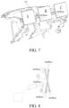
FIG. 7 is a combined view of a plurality of in-vehicle display terminals and an air outlet assembly of an air outlet device for an air-conditioning system of a vehicle, according to some embodiments of the present invention; -
FIG. 8 is a schematic diagram of rotation of an in-vehicle display terminal; -
FIG. 9 is a schematic principle diagram of a regional temperature difference of an air-conditioning system; -
FIG. 10 is a schematic block diagram of a vehicle according to an embodiment of the present invention; and -
FIG. 11 is a flowchart of an air outlet method for an air-conditioning system of a vehicle according to an embodiment of the present invention. - The embodiments of the present invention are described below in detail. Examples of the embodiments are shown in the accompanying drawings, and same or similar reference signs in all the accompanying drawings indicate same or similar components or components having same or similar functions. The embodiments described below with reference to the accompanying drawings are exemplary, and are intended to explain the present invention and cannot be construed as a limitation to the present invention.
- A method and an apparatus of the embodiments of the present invention are described below with reference to the accompanying drawings.
-
FIG. 1 is a schematic block diagram of an air outlet device for an air-conditioning system of a vehicle according to some embodiments of the present invention. - As shown in
FIG. 1 , the air outlet device for an air-conditioning system of a vehicle according to some embodiments of the present invention includes: anair outlet assembly 10 disposed at air vents of the air-conditioning system and acontrol unit 20. - The
air outlet assembly 10 includes a plurality offirst air doors 11 and a plurality of drivingcomponents 12. The plurality of drivingcomponents 12 are respectively connected to the plurality offirst air doors 11. Each drivingcomponent 12 is configured to drive the correspondingfirst air door 11. Thecontrol unit 20 is connected to the plurality of drivingcomponents 12. Thecontrol unit 20 is configured to control the plurality of drivingcomponents 12 to drive the plurality offirst air doors 11 to open or close independently. - According to an embodiment of the present invention, as shown in
FIG. 2 , each drivingcomponent 12 may include: agear 121, arack 122, and a motor (not specifically shown in the figure). Thegear 121 is connected to the correspondingfirst air door 11, to drive thefirst air door 11 to move. Therack 122 cooperates with thegear 121 to drive thegear 121 to rotate. The motor is connected to therack 122, and is configured to drive therack 122 under the control of thecontrol unit 20. Theair outlet assembly 10 is installed behind in-vehicle display terminals, such as being installed on a dashboard. Theair outlet assembly 10 may have a structure extending left and right, and may be adaptively extended and contracted according to a quantity of the in-vehicle display terminals. - Therefore, by using the air outlet device for the present invention, the plurality of first air doors are controlled to open or close independently, thereby saving energy while ensuring that the air vents are not blocked. According to some embodiments of the present invention, as shown in
FIG. 3 , the foregoing air outlet device for an air-conditioning system of a vehicle further includes: aposition detection unit 30, configured to detect positions of a plurality of in-vehicle display terminals of the vehicle. The plurality of in-vehicle display terminals are disposed in front of theair outlet assembly 10. Thecontrol unit 20 controls the plurality of drivingcomponents 12 according to the positions of the plurality of in-vehicle display terminals and/or rotation states of the plurality of in-vehicle display terminals. - In other words, according to the positions of the plurality of in-vehicle display terminals, the plurality of driving
components 12 drive the plurality offirst air doors 11 to open or close independently. For example, as shown inFIG. 5 , according to a position of an in-vehicle display terminal A, a plurality of driving components drive a plurality of first air doors in a region blocked by the in-vehicle display terminal to close. According to the rotation states of the plurality of in-vehicle display terminals, the plurality of drivingcomponents 12 drive the plurality of first air doors to open or close independently. For example, as shown inFIG. 5 , rotation states of the in-vehicle display terminal A, an in-vehicle display terminal B, and an in-vehicle display terminal C are different, and quantities of first air doors that are blocked by the in-vehicle display terminals A, B, and C are also different. In this case, thecontrol unit 20 controls a plurality of driving components in regions blocked by the in-vehicle display terminals A, B, and C to drive a plurality of corresponding first air doors to close, and controls a plurality of driving components outside the regions blocked by the in-vehicle display terminals A, B, and C to drive a plurality of corresponding first air doors to open, thereby achieving the air outlet effect and saving energy. The plurality of driving components are further controlled according to the positions of the plurality of in-vehicle display terminals and the rotation states of plurality of in-vehicle display terminals, to realize more precise control. - According to an embodiment of the present invention, the
control unit 20 is further configured to determine a blocked region and an unblocked region of theair outlet assembly 10 according to the positions of the plurality of in-vehicle display terminals and the rotation states of the plurality of in-vehicle display terminals, and controlfirst air doors 11 in the blocked region to close andfirst air doors 11 in the unblocked region to open. The blocked region is an air outlet region of the air outlet assembly that is blocked by the in-vehicle display terminal, that is, a region from which the air outlet assembly cannot let out air. The unblocked region is an air outlet region of the air outlet assembly that is not blocked by the in-vehicle display terminal, that is, a region from which the air outlet assembly can normally let out air. - In other words, all the
first air doors 11 in the blocked region are controlled to be closed, which can save energy; and all the first air doors in the unblocked region are controlled to be open, which can satisfy a requirement for temperature adjustment of a driver. In addition, in a case that the driver has a heating requirement, closing all thefirst air doors 11 in the blocked region can effectively avoid the continuous temperature rise in the blocked region, and equipment aging or safety hazards due to the temperature rise for a long time. - It should be noted that, in a case that a part of a certain first air door in the plurality of first air doors is blocked by an in-vehicle display terminal, an air outlet region where the certain first air door is located also belongs to the blocked region. In this case, the first air door is controlled to be closed.
- Specifically, as shown in
FIG. 4 , the in-vehicle display terminals are connected to universal ball heads for rotation, so as to change display directions of the in-vehicle display terminals. In addition, the in-vehicle display terminals slide left and right on a guide rail driven by drive motors of the in-vehicle display terminals, to change the positions of the in-vehicle display terminals. In this way, the in-vehicle display terminals may be spliced together to form a large display screen, or may be combined into different forms. For example, as shown inFIG. 5 and FIG. 6 , A, B, and C represent the in-vehicle display terminals, and arrow directions represent movement directions and rotation directions of the in-vehicle display terminals. It is assumed that sizes of the in-vehicle display terminals A, B, and C are all 20 cm * 15 cm (length * width), a large display screen of 60 cm * 15 cm may be obtained by splicing as shown inFIG. 5 , and a large display screen of 45 cm * 20 cm may be obtained by splicing as shown inFIG. 6 . - It may be understood that,
FIG. 5 FIG. 6 merely illustrate some embodiments of the present invention. The present invention includes but is not limited to three in-vehicle display terminals, and may alternatively include two or four in-vehicle display terminals, or the like. - A laser sensor is disposed in the
air outlet assembly 10. The laser sensor is configured to detect position information of the in-vehicle display terminals according to a distance setting, and transmit the position information to thecontrol unit 20 through a controller area network (CAN) signal. The control unit 20 (for example, thecontrol unit 20 may be a micro controller unit (MCU)) drives, according to received position information, the motors to control thefirst air doors 11 to open or close. For example, in a case that the position of the in-vehicle display terminal A blocks the correspondingfirst air doors 11, thecontrol unit 20 controls the air doors corresponding to the position to close and thefirst air doors 11 corresponding to the unblocked regions to open. - In other words, as shown in
FIG. 7 , as a position of an in-vehicle display terminal moves, the position detection unit 30 (for example, the laser sensor) acquires the position of the in-vehicle display terminal. According to the position of the in-vehicle display terminal, thecontrol unit 20 controls the opening and closing states of the air vents at different positions. The quantities of the air vents that are blocked are different when the in-vehicle display terminal is in a landscape state and a portrait state. In a case that theposition detection unit 30 acquires a position change, the quantities of the opening and closing states of the plurality of first air doors may also change correspondingly. Therefore, the air doors that are blocked by the positions of the in-vehicle display terminals can be closed, and the air doors in the regions that are not blocked by the in-vehicle display terminals can be opened, so as to prevent airflow from being blocked by the in-vehicle display terminals. In this way, air can flow out from the unblocked regions, to maximize the energy of the airflow, thereby realizing energy conservation and environmental protection. - According to some embodiments of the present invention, the
control unit 20 is further configured to determine a blocked region and an unblocked region of theair outlet assembly 10 according to the positions of the plurality of in-vehicle display terminals and the rotation states of the plurality of in-vehicle display terminals, control allfirst air doors 11 in the blocked region and the unblocked region to open, and control the corresponding in-vehicle display terminal in the blocked region to rotate, so as to change an air outlet direction. - According to some embodiments of the present invention, the
control unit 20 is further configured to receive a user instruction, and control at least one of thefirst air doors 11 in the blocked region to open according to the user instruction. - Specifically, as shown in
FIG. 8 , in a case that an in-vehicle display terminal blocks first air doors, in order to dissipate heat from the in-vehicle display terminal, a temperature sensor (not shown in the figure) may be disposed on the in-vehicle display terminal to detect a temperature of the in-vehicle display terminal, and feed back a high-temperature region of the in-vehicle display terminal to thecontrol unit 20. Thecontrol unit 20 may further control at least one offirst air doors 11 corresponding to the high-temperature region of the in-vehicle display terminal in the blocked region to open, so as to dissipate heat from the in-vehicle display terminal; and control the universal ball head to rotate the in-vehicle display terminal, so as to change the air outlet direction of thefirst air door 11, thereby blowing air into the vehicle while dissipating heat from the in-vehicle display terminal. Blowing cold air can dissipate heat from the plurality of in-vehicle display terminals. - According to some embodiments of the present invention, as shown in
FIG. 9 , the air-conditioning system may include anair duct 40, anevaporator 50, and awarm box 60. Theevaporator 50 is configured to generate cold air. Thewarm box 60 is configured to generate warm air. Theair outlet device 110 may further include: abaffle 70 disposed in theair duct 40, thebaffle 70 being disposed along a flow direction of air in theair duct 40, to separate theair duct 40 into a plurality of partitioned air ducts (the plurality of partitioned air duct divide the air duct into a plurality of regions); and a plurality ofsecond air doors 80 disposed between the evaporator and the warm box, the plurality ofsecond air doors 80 being correspondingly disposed in the plurality of partitioned air ducts respectively, and each second air door being configured to control a flow rate of cold air in the corresponding partitioned air duct. Thecontrol unit 20 is configured to control opening degrees of the plurality of second air doors. Each partitioned air duct corresponds to first air doors in a certain region. For example, as shown inFIG. 9 , the partitioned air duct in the upper part of the figure corresponds to controlling a plurality of first air doors in the unblocked region to open, to blow out warm airflow; and the partitioned air duct in the lower part of the figure corresponds to controlling a plurality of first air doors in the unblocked region to open, to blow out cold airflow. It may be understood that, the upper part shown inFIG. 9 may also blow out cold airflow, and the lower part may also blow out warm airflow, which may be defined according to actual requirements. - It should be noted that, the second air doors are rotatable or movable.
- According to some embodiments of the present invention, in a case that there are plural unblocked regions of the air outlet assembly, the
control unit 20 is further configured to obtain a target air outlet temperature of each unblocked region, and control the opening degree of the second air door in the partitioned air duct corresponding to each unblocked region according to the target air outlet temperature of each unblocked region. - Specifically, as shown in
FIG. 9 , the present invention can further implement different air outlet temperatures in different air outlet regions. The airflow enters the partitioned air ducts through the isolated evaporator and the warm box with the baffle, and then flows out of the air outlet assembly. The second air doors (air vent open-and-close units) are disposed between the evaporator and the warm box. An opening and closing amount of each second air door is controlled to implement cooling and heating control. For example, in a case that the target outlet temperature between the in-vehicle display terminals B and C is detected to be high, thecontrol unit 20 may increase an opening degree of a corresponding second air door to increase a flow rate of cold airflow flowing through, so as to increase a flow rate of cold airflow entering the warm box and reduce a temperature of warm airflow flowing out of the warm box, thereby reducing the target air outlet temperature. In a case that the target outlet temperature between the in-vehicle display terminals A and B is detected to be high, thecontrol unit 20 may increase an opening degree of a corresponding second air door to increase a flow rate of cold airflow flowing through, so as to increase a flow rate of cold airflow entering the warm box and reduce a temperature of warm airflow flowing out of the warm box, thereby reducing the target air outlet temperature. In this way, different air vents blow out airflow with different temperatures. Specifically, in a case that a temperature of a region facing the in-vehicle display terminal is 20°C while a required temperature of a driver is 23°C, the opening degree of the second air door may be adjusted to satisfy the requirement of the driver. - In conclusion, in the air outlet device for an air-conditioning system of a vehicle provided in the present invention, the opening and closing states of the air outlet assembly can be controlled through movement of the in-vehicle display terminals, to control the airflow direction, thereby preventing the airflow from being blocked. The airflow is controlled to dissipate heat from the in-vehicle display terminals. The direction of the airflow is guided through the in-vehicle display terminals, to satisfy the comfort of passengers.
- Based on the above, according to the air outlet device for an air-conditioning system of a vehicle provided in some embodiments of the present invention, the control unit is connected to the plurality of driving components. By controlling the plurality of driving components to drive the plurality of first air doors to open or close independently, the opening and closing states of the air outlet assembly can be controlled, so as to control an airflow direction, thereby preventing airflow from being blocked, and satisfying the comfort of passengers.
-
FIG. 10 is a schematic block diagram of a vehicle according to an embodiment of the present invention. - As shown in
FIG. 10 , thevehicle 100 according to an embodiment of the present invention includes: the foregoingair outlet device 110 of an air-conditioning system of a vehicle. - The vehicle according to an embodiment of the present invention can control the airflow direction by using the foregoing air outlet device for an air-conditioning system of a vehicle, thereby preventing the airflow from being blocked, and satisfying the comfort of passengers.
- According to the foregoing embodiments, the present invention further provides an air outlet method for an air-conditioning system of a vehicle.
- In an embodiment of the present invention, an air outlet assembly is disposed at air vents of the air-conditioning system. The air outlet assembly includes a plurality of first air doors and a plurality of driving components. The plurality of driving components are respectively connected to the plurality of first air doors. Each driving component is configured to drive the corresponding first air door.
-
FIG. 11 is a flowchart of an air outlet method for an air-conditioning system of a vehicle according to an embodiment of the present invention. - As shown in
FIG. 11 , the air outlet method for an air-conditioning system of a vehicle according to an embodiment of the present invention includes the following step: S1. Control a plurality of driving components to drive a plurality of first air doors to open or close independently. - It should be noted that reference is made to the details disclosed in the air outlet device for an air-conditioning system of a vehicle according to the embodiments of the present invention for details that are not disclosed in the air outlet method for an air-conditioning system of a vehicle according to the embodiments of the present invention, and no repeated description is provided herein.
- By using the air outlet method for an air-conditioning system of a vehicle according to an embodiment of the present invention, the plurality of driving components are controlled to drive the plurality of first air doors to open or close independently, so as to control the airflow direction, thereby preventing the airflow from being blocked, and satisfying the comfort of passengers.
- In the description of this specification, the description of the reference terms such as "an embodiment", "some embodiments", "example", "specific example", or "some examples" means that the specific features, structures, materials or characteristics described with reference to the embodiment or example are included in at least one embodiment or example of the present invention. In the present specification, schematic representations of the above terms are not necessarily directed to the same embodiments or examples. Moreover, the specific features, structures, materials, or characteristics described may be combined in any one or more embodiments or examples in a suitable manner. In addition, different embodiments or examples described in the present specification, as well as features of different embodiments or examples, may be integrated and combined by those skilled in the art without contradicting each other.
- In addition, terms "first" and "second" are used merely for the purpose of description, and shall not be construed as indicating or implying relative importance or implying a quantity of indicated technical features. Therefore, features defining "first" and "second" can explicitly or implicitly include at least one of the features. In the descriptions of the present invention, unless explicitly specified, "multiple" means at least two, for example, two or three.
- Any process or method description in the flowchart or described in other ways herein can be understood as a module, segment or part of a code that includes one or more executable instructions for implementing customized logic functions or steps of the process, and the scopes of the preferred embodiments of the present invention include additional implementations, which may not be in the order shown or discussed, including performing functions in a substantially simultaneous manner or in reverse order according to the functions involved. This should be understood by a person skilled in the art to which the embodiments of the present invention belong.
- The logic and/or steps shown in the flowcharts or described in any other manner herein, for example, a sequenced list that may be considered as executable instructions used for implementing logical functions, may be specifically implemented in any computer readable medium to be used by an instruction execution system, apparatus, or device (for example, a computer-based system, a system including a processor, or another system that can obtain an instruction from the instruction execution system, apparatus, or device and execute the instruction) or to be used by combining such instruction execution systems, apparatuses, or devices. In the context of the present invention, a "computer-readable medium" may be any apparatus that can include, store, communicate, propagate, or transmit the program for use by the instruction execution system, apparatus, or device or in combination with the instruction execution system, apparatus, or device. More specific examples (a non-exhaustive list) of the computer-readable medium include the following: an electrical connection (electronic device) having one or more wires, a portable computer diskette (magnetic apparatus), a random access memory (RAM), a read-only memory (ROM), an erasable programmable read-only memory (EPROM or flash memory), an optical fiber apparatus, and a portable compact disk read-only memory (CDROM). In addition, the computer-readable medium can even be paper or other suitable media on which the program can be printed, because the program can be obtained electronically by, for example, optically scanning paper or other media, then editing, interpreting, or processing in other suitable ways if necessary, and then storing it in a computer memory.
- It should be understood that, parts of the present invention can be implemented by using hardware, software, firmware, or a combination thereof. In the foregoing implementations, a plurality of steps or methods may be implemented by using software or firmware that are stored in a memory and are executed by a proper instruction execution system. For example, if hardware is used for implementation, same as in another implementation, implementation may be performed by any one of the following technologies well known in the art or a combination thereof: a discrete logic circuit of a logic gate circuit for realizing a logic function for a data signal, an application-specific integrated circuit having a suitable combined logic gate circuit, a programmable gate array (PGA), and a field programmable gate array (FPGA).
- A person of ordinary skill in the art may understand that all or some of the steps of the methods in the foregoing embodiments may be implemented by a program instructing relevant hardware. The program may be stored in a computer-readable storage medium. When the program is executed, one or a combination of the steps of the method embodiments are performed.
- In addition, the functional modules in the embodiments of the present invention may be integrated into one processing module, or each of the units may exist alone physically, or two or more units may be integrated into one module. The integrated module may be implemented in the form of hardware, or may be implemented in a form of a software functional module. If implemented in the form of software functional modules and sold or used as an independent product, the integrated module may also be stored in a computer-readable storage medium.
- The storage medium mentioned above may be a read-only memory, a magnetic disk, an optical disc, or the like. Although the embodiments of the present invention have been shown and described above, it can be understood that, the foregoing embodiments are exemplary and should not be understood as limitation to the present invention. A person of ordinary skill in the art can make changes, modifications, replacements, or variations to the foregoing embodiments within the scope of the invention as defined in the appended claims.
Claims (11)
- An air outlet device (110) for an air-conditioning system of a vehicle (100), comprising:an air outlet assembly (10) configured to be disposed at air vents of the air-conditioning system, the air outlet assembly (10) comprising a plurality of first air doors (11) and a plurality of 5 driving components (12), the plurality of driving components (12) being respectively connected to the plurality of first air doors (11), and each of the driving components (12) being configured to drive a corresponding first air door (11);a control unit (20), the control unit (20) being connected to the plurality of driving components (12), and being configured to control the plurality of driving components (12) to drive the plurality of first air doors (11) to open or close independently;characterized in that the air outlet device (110) further comprises:a position detection unit (30), the position detection unit (30) being configured to detect positions of a plurality of in-vehicle display terminals (A, B, C) of the vehicle (100), the plurality of in-vehicle display terminals (A, B, C) being configured to be disposed in front of the air outlet assembly (10),in that the control unit (20) is configured to control the plurality of driving components (12) according to the positions of the plurality of in-vehicle display terminals (A, B, C) and rotation states of the plurality of in-vehicle display terminals (A, B, C); andin that the control unit (20) is further configured to determine a blocked region of the air outlet assembly (10), wherein the blocked region is an air outlet region of the air outlet assembly (10) that is blocked by an in-vehicle display terminal (A, B, C), from which the air outlet assembly (10) cannot let out air and an unblocked region of the air outlet assembly (10), wherein the unblocked region is an air outlet region of the air outlet assembly (10) that is not blocked by an in-vehicle display terminal (A, B, C), from which the air outlet assembly (10) can let out air according to the positions of the plurality of in-vehicle display terminals (A, B, C) and the rotation states of the plurality of in-vehicle display terminals (A, B, C), and control first air doors among the plurality of first air doors (11) in the blocked region to close and first air doors among the plurality of first air doors (11) in the unblocked region to open.
- The air outlet device (110) for an air-conditioning system of a vehicle (100), according to claim 1, wherein the control unit (20) is further configured to control first air doors among the plurality of first air doors (11) in the blocked region and first air doors among the plurality of first air doors (11) in the unblocked region to open, and control a corresponding in-vehicle display terminal among the plurality of in-vehicle display terminals (A, B, C) in the blocked region to rotate, to change an air outlet direction.
- The air outlet device (110) for an air-conditioning system of a vehicle (100), according to claim 1 or 2, wherein the control unit (20) is further configured to receive a user instruction, and control at least one of the first air doors (11) in the blocked region to open according to the user instruction.
- The air outlet device (110) for an air-conditioning system of a vehicle (100), according to any one of the previous claims, further comprising:a baffle (70) configured to be disposed in an air duct (40) of the air-conditioning system, the baffle (70) being configured to be disposed along a flow direction of air in the air duct (40), to divide the air duct (40) into a plurality of partitioned air ducts; anda plurality of second air doors (80) configured to be disposed between an evaporator (50) and a warm box (60) of the air-conditioning system, the evaporator (50) is configured to generate cold air, and the warm box (60) is configured to generate warm air, the plurality of second air doors (80) being configured to be respectively disposed in the plurality of partitioned air ducts, and each of the second air doors (80) being configured to control a flow rate of cold air in the corresponding partitioned air duct,wherein the control unit (20) is configured to control opening degrees of the plurality of second air doors (80).
- The air outlet device (110) for an air-conditioning system of a vehicle (100), according to claim 4, wherein each partitioned air duct is configured to correspond to first air doors (11) in a certain region, wherein when the unblocked region is one of a plurality of unblocked regions of the air outlet assembly (10), the control unit (20) is further configured to obtain a target air outlet temperature of each of the unblocked regions, and control the opening degree of the second air door (80) in the partitioned air duct corresponding to each of the unblocked regions according to the target air outlet temperature of each of the unblocked regions.
- A vehicle (100), comprising the air outlet device (110) for an air-conditioning system of a vehicle (100), according to any one of claims 1 to 5.
- An air outlet method for an air-conditioning system of a vehicle (100), wherein an air outlet assembly (10) is disposed at air vents of the air-conditioning system, the air outlet assembly (10) comprises a plurality of first air doors (11) and a plurality of driving components (12), the plurality of driving components (12) are respectively connected to the plurality of first air doors (11), and each of the driving components (12) is configured to drive a corresponding first air door (11); and the air outlet method comprises the following step:
controlling (S1) the plurality of driving components (12) to drive the plurality of first air doors (11) to open or close independently;
characterized in that the controlling (S1) the plurality of driving components (12) comprises:detecting positions of a plurality of in-vehicle display terminals (A, B, C) of the vehicle (100), the plurality of in-vehicle display terminals (A, B, C) being disposed in front of the air outlet assembly (10); andcontrolling the plurality of driving components (12) according to the positions of the plurality of in-vehicle display terminals (A, B, C) and rotation states of the plurality of in-vehicle display terminals (A, B, C); andin that the controlling the plurality of driving components (12) according to the positions of the plurality of in-vehicle display terminals (A, B, C) and rotation states of the plurality of in-vehicle display terminals (A, B, C) comprises:determining a blocked region of the air outlet assembly (10), wherein the blocked region is an air outlet region of the air outlet assembly (10) that is blocked by an in-vehicle display terminal (A, B, C), from which the air outlet assembly (10) cannot let out air and an unblocked region of the air outlet assembly (10), wherein the unblocked region is an air outlet region of the air outlet assembly (10) that is not blocked by an in-vehicle display terminal (A, B, C), from which the air outlet assembly (10) can let out air according to the positions of the plurality of in-vehicle display terminals (A, B, C) and the rotation states of the plurality of in-vehicle display terminals (A, B, C); andcontrolling first air doors among the plurality of first air doors (11) in the blocked region to close and first air doors among the plurality of first air doors (11) in the unblocked region to open. - The air outlet method for an air-conditioning system of a vehicle (100), according to claim 7, whereinthe controlling the plurality of driving components (12) according to the positions of the plurality ofin-vehicle display terminals (A, B, C) and rotation states of the plurality of in-vehicle display terminal (A, B, C) comprises:
controlling first air doors among the plurality of first air doors (11) in the blocked region and first air doors among the plurality of first air doors (11) in the unblocked region to open, and controlling a corresponding in-vehicle display terminal among the plurality of in-vehicle display terminals (A, B, C) in the blocked region to rotate, to change an air outlet direction. - The air outlet method for an air-conditioning system of a vehicle (100), according to claim 7 or 8, further comprising:
receiving a user instruction, and controlling at least one of the first air doors (11) in the blocked region to open according to the user instruction. - The air outlet method for an air-conditioning system of a vehicle (100), according to any one of claims 7 to 9, wherein the air-conditioning system comprises an air duct (40), an evaporator (50), and a warm box (60), the evaporator (50) is configured to generate cold air, and the warm box (60) is configured to generate warm air; a baffle (70) is disposed in the air duct (40), and is disposed along a flow direction of air in the air duct (40), to divide the air duct (40) into a plurality of partitioned air ducts; and a plurality of second air doors (80) are disposed between the evaporator (50) and the warm box (60), the plurality of second air doors (80) are respectively disposed in the plurality of partitioned air ducts, and each of the second air doors (80) is configured to control a flow rate of cold air in the corresponding partitioned air duct; and the air outlet method further comprises:
controlling opening degrees of the plurality of second air doors (80). - The air outlet method for an air-conditioning system of a vehicle (100), according to claim 10,wherein each partitioned air duct corresponds to first air doors (80) in a certain region, wherein when the unblocked region is one of a plurality unblocked regions of the air outlet assembly (10), the controlling opening degrees of the plurality of second air doors (80) comprises:
obtaining a target air outlet temperature of each of the unblocked regions; andcontrolling the opening degree of the second air door (80) in the partitioned air duct corresponding to each of the unblocked regions according to the target air outlet temperature of each of the unblocked regions.
Applications Claiming Priority (2)
| Application Number | Priority Date | Filing Date | Title |
|---|---|---|---|
| CN201910213924.2A CN111716998B (en) | 2019-03-20 | 2019-03-20 | Vehicle and air outlet device and air outlet method of air conditioning system of vehicle |
| PCT/CN2020/079043 WO2020187130A1 (en) | 2019-03-20 | 2020-03-12 | Vehicle and air outlet device and air outlet method for air conditioning system thereof |
Publications (3)
| Publication Number | Publication Date |
|---|---|
| EP3943323A1 EP3943323A1 (en) | 2022-01-26 |
| EP3943323A4 EP3943323A4 (en) | 2022-04-20 |
| EP3943323B1 true EP3943323B1 (en) | 2023-07-12 |
Family
ID=72519188
Family Applications (1)
| Application Number | Title | Priority Date | Filing Date |
|---|---|---|---|
| EP20773938.4A Active EP3943323B1 (en) | 2019-03-20 | 2020-03-12 | Air outlet device and air outlet method for an air conditioning system of a vehicle |
Country Status (4)
| Country | Link |
|---|---|
| US (1) | US20220144041A1 (en) |
| EP (1) | EP3943323B1 (en) |
| CN (1) | CN111716998B (en) |
| WO (1) | WO2020187130A1 (en) |
Families Citing this family (8)
| Publication number | Priority date | Publication date | Assignee | Title |
|---|---|---|---|---|
| WO2022174910A1 (en) * | 2021-02-19 | 2022-08-25 | Huawei Technologies Co., Ltd. | Vehicle infotainment system |
| CN112706587B (en) * | 2021-03-26 | 2021-06-18 | 宁波均胜群英汽车系统股份有限公司 | Air outlet of automobile air conditioner |
| WO2023171829A1 (en) * | 2022-03-08 | 2023-09-14 | 엘지전자 주식회사 | Display device for vehicle |
| DE102023103055A1 (en) * | 2023-02-08 | 2024-08-08 | Audi Aktiengesellschaft | Thermal management system for a motor vehicle and method for cooling electronic devices in a passenger compartment as needed |
| FR3147970B1 (en) * | 2023-04-19 | 2025-03-07 | Psa Automobiles Sa | Device for supporting an object in a ventilation opening. |
| CN116619982B (en) * | 2023-06-29 | 2025-12-16 | 赛力斯汽车有限公司 | Air outlet motor control method and device, electronic equipment and storage medium |
| WO2025126511A1 (en) * | 2023-12-13 | 2025-06-19 | 株式会社デンソーテン | Display device and information processing device |
| EP4717480A1 (en) * | 2024-09-27 | 2026-04-01 | Nxp B.V. | An automotive controller |
Family Cites Families (15)
| Publication number | Priority date | Publication date | Assignee | Title |
|---|---|---|---|---|
| US4844120A (en) * | 1988-04-27 | 1989-07-04 | Myers Melvin J | Motorized control damper |
| JP2915097B2 (en) * | 1990-06-26 | 1999-07-05 | マツダ株式会社 | Car air conditioner |
| JP4281179B2 (en) * | 1998-11-25 | 2009-06-17 | 株式会社デンソー | Air conditioner for vehicles |
| US8561738B2 (en) * | 2010-11-30 | 2013-10-22 | GM Global Technology Operations LLC | Compound shutter system with independent and non-sequential operation |
| KR20140026928A (en) * | 2012-08-24 | 2014-03-06 | 오수건 | A grille system for air duct of vehicles |
| US10449828B2 (en) * | 2014-05-15 | 2019-10-22 | ValTec, LLC | System for controlling air flow into the passenger compartment of a vehicle |
| DE202014007673U1 (en) * | 2014-09-20 | 2016-01-14 | GM Global Technology Operations LLC (n. d. Ges. d. Staates Delaware) | Device for mounting on an instrument panel of a motor vehicle |
| US20160123621A1 (en) * | 2014-11-05 | 2016-05-05 | Thesmartvent Llc | Fully Close Vent Device for Heating and Air Conditioning System |
| CN107074063B (en) * | 2014-12-02 | 2019-07-26 | 翰昂汽车零部件有限公司 | Left/Right Independent Air Conditioner for Vehicles |
| DE102015218309B4 (en) * | 2015-09-23 | 2026-01-29 | Volkswagen Aktiengesellschaft | Ventilation nozzle for ventilating a vehicle interior |
| US20170291469A1 (en) * | 2016-04-08 | 2017-10-12 | Ford Global Technologies, Llc | Electronic ventilation register control system for a motor vehicle |
| US10384510B2 (en) * | 2016-11-23 | 2019-08-20 | Hanon Systems | HVAC variant for autonomous vehicle |
| CN108099803B (en) * | 2016-11-24 | 2020-02-21 | 比亚迪股份有限公司 | Vehicle display and air outlet components and vehicles |
| CN206510720U (en) * | 2017-01-04 | 2017-09-22 | 浙江大学 | A kind of multi-fan refrigerating module of the controllable air door of band |
| CN107940723B (en) * | 2017-11-23 | 2020-03-10 | Tcl空调器(中山)有限公司 | Wind sweeping mechanism and air conditioner thereof |
-
2019
- 2019-03-20 CN CN201910213924.2A patent/CN111716998B/en active Active
-
2020
- 2020-03-12 EP EP20773938.4A patent/EP3943323B1/en active Active
- 2020-03-12 US US17/440,324 patent/US20220144041A1/en not_active Abandoned
- 2020-03-12 WO PCT/CN2020/079043 patent/WO2020187130A1/en not_active Ceased
Also Published As
| Publication number | Publication date |
|---|---|
| EP3943323A1 (en) | 2022-01-26 |
| CN111716998A (en) | 2020-09-29 |
| CN111716998B (en) | 2022-03-18 |
| WO2020187130A1 (en) | 2020-09-24 |
| EP3943323A4 (en) | 2022-04-20 |
| US20220144041A1 (en) | 2022-05-12 |
Similar Documents
| Publication | Publication Date | Title |
|---|---|---|
| EP3943323B1 (en) | Air outlet device and air outlet method for an air conditioning system of a vehicle | |
| CN113405161B (en) | Air conditioner, control method thereof and computer readable storage medium | |
| JP6185161B2 (en) | Control method of air-conditioning air guide plate | |
| CN103358890B (en) | There is the angled venetian blinds of Dual Drive actuating mechanism | |
| US11263841B2 (en) | Data storage library with service mode | |
| JP6031891B2 (en) | Grill with air volume adjustment mechanism and air volume adjustment system | |
| EP2332757B1 (en) | Air conditioning device for vehicle, and method and program for controlling air conditioning device for vehicle | |
| EP3693675A1 (en) | Air-conditioning indoor unit and air conditioner having same | |
| US10436472B2 (en) | Air conditioner and method of controlling the same | |
| JPS6258929B2 (en) | ||
| CN111414062A (en) | Electronic apparatus and control method | |
| CN115570929A (en) | Independent Radiator and Condenser Controls | |
| CN114413335A (en) | Air outlet mechanism, air conditioner and air supply control method | |
| JP2011196617A (en) | Air conditioning system and air conditioning method | |
| CN113251565A (en) | Air conditioner air outlet control method and device, storage medium, processor and air conditioner | |
| CN103019195A (en) | Radiating control system, method and device | |
| CN110749069B (en) | Air conditioner control method and system and air conditioner | |
| CA3055363A1 (en) | Hvac-less enclosure with temperature range augmenting recirculation system | |
| CN110822673B (en) | Control method and device of air conditioner and air conditioner | |
| US20240066950A1 (en) | Multidirectional vent for vehicle hvac system | |
| CN115900006B (en) | Method, apparatus, air conditioner, and storage medium for controlling an air conditioner | |
| US10823185B2 (en) | Motor interface assembly and a method of using the same | |
| KR102335385B1 (en) | Hvac of vehicle having sliding type door | |
| CN110779179A (en) | Air conditioner and control method and control device thereof | |
| JP2016078746A (en) | Cooling module |
Legal Events
| Date | Code | Title | Description |
|---|---|---|---|
| STAA | Information on the status of an ep patent application or granted ep patent |
Free format text: STATUS: THE INTERNATIONAL PUBLICATION HAS BEEN MADE |
|
| PUAI | Public reference made under article 153(3) epc to a published international application that has entered the european phase |
Free format text: ORIGINAL CODE: 0009012 |
|
| STAA | Information on the status of an ep patent application or granted ep patent |
Free format text: STATUS: REQUEST FOR EXAMINATION WAS MADE |
|
| 17P | Request for examination filed |
Effective date: 20211014 |
|
| AK | Designated contracting states |
Kind code of ref document: A1 Designated state(s): AL AT BE BG CH CY CZ DE DK EE ES FI FR GB GR HR HU IE IS IT LI LT LU LV MC MK MT NL NO PL PT RO RS SE SI SK SM TR |
|
| REG | Reference to a national code |
Ref country code: DE Ref legal event code: R079 Free format text: PREVIOUS MAIN CLASS: B60H0001340000 Ipc: B60H0001000000 Ref document number: 602020013810 Country of ref document: DE |
|
| A4 | Supplementary search report drawn up and despatched |
Effective date: 20220321 |
|
| RIC1 | Information provided on ipc code assigned before grant |
Ipc: B60K 37/02 20060101ALI20220315BHEP Ipc: B60H 1/34 20060101ALI20220315BHEP Ipc: B60H 1/24 20060101ALI20220315BHEP Ipc: B60H 1/00 20060101AFI20220315BHEP |
|
| DAV | Request for validation of the european patent (deleted) | ||
| DAX | Request for extension of the european patent (deleted) | ||
| GRAP | Despatch of communication of intention to grant a patent |
Free format text: ORIGINAL CODE: EPIDOSNIGR1 |
|
| STAA | Information on the status of an ep patent application or granted ep patent |
Free format text: STATUS: GRANT OF PATENT IS INTENDED |
|
| INTG | Intention to grant announced |
Effective date: 20230131 |
|
| GRAS | Grant fee paid |
Free format text: ORIGINAL CODE: EPIDOSNIGR3 |
|
| GRAA | (expected) grant |
Free format text: ORIGINAL CODE: 0009210 |
|
| STAA | Information on the status of an ep patent application or granted ep patent |
Free format text: STATUS: THE PATENT HAS BEEN GRANTED |
|
| AK | Designated contracting states |
Kind code of ref document: B1 Designated state(s): AL AT BE BG CH CY CZ DE DK EE ES FI FR GB GR HR HU IE IS IT LI LT LU LV MC MK MT NL NO PL PT RO RS SE SI SK SM TR |
|
| P01 | Opt-out of the competence of the unified patent court (upc) registered |
Effective date: 20230527 |
|
| REG | Reference to a national code |
Ref country code: CH Ref legal event code: EP |
|
| REG | Reference to a national code |
Ref country code: IE Ref legal event code: FG4D |
|
| REG | Reference to a national code |
Ref country code: DE Ref legal event code: R096 Ref document number: 602020013810 Country of ref document: DE |
|
| REG | Reference to a national code |
Ref country code: LT Ref legal event code: MG9D |
|
| REG | Reference to a national code |
Ref country code: NL Ref legal event code: MP Effective date: 20230712 |
|
| REG | Reference to a national code |
Ref country code: AT Ref legal event code: MK05 Ref document number: 1586772 Country of ref document: AT Kind code of ref document: T Effective date: 20230712 |
|
| PG25 | Lapsed in a contracting state [announced via postgrant information from national office to epo] |
Ref country code: NL Free format text: LAPSE BECAUSE OF FAILURE TO SUBMIT A TRANSLATION OF THE DESCRIPTION OR TO PAY THE FEE WITHIN THE PRESCRIBED TIME-LIMIT Effective date: 20230712 |
|
| PG25 | Lapsed in a contracting state [announced via postgrant information from national office to epo] |
Ref country code: GR Free format text: LAPSE BECAUSE OF FAILURE TO SUBMIT A TRANSLATION OF THE DESCRIPTION OR TO PAY THE FEE WITHIN THE PRESCRIBED TIME-LIMIT Effective date: 20231013 |
|
| PG25 | Lapsed in a contracting state [announced via postgrant information from national office to epo] |
Ref country code: ES Free format text: LAPSE BECAUSE OF FAILURE TO SUBMIT A TRANSLATION OF THE DESCRIPTION OR TO PAY THE FEE WITHIN THE PRESCRIBED TIME-LIMIT Effective date: 20230712 |
|
| PG25 | Lapsed in a contracting state [announced via postgrant information from national office to epo] |
Ref country code: IS Free format text: LAPSE BECAUSE OF FAILURE TO SUBMIT A TRANSLATION OF THE DESCRIPTION OR TO PAY THE FEE WITHIN THE PRESCRIBED TIME-LIMIT Effective date: 20231112 |
|
| PG25 | Lapsed in a contracting state [announced via postgrant information from national office to epo] |
Ref country code: SE Free format text: LAPSE BECAUSE OF FAILURE TO SUBMIT A TRANSLATION OF THE DESCRIPTION OR TO PAY THE FEE WITHIN THE PRESCRIBED TIME-LIMIT Effective date: 20230712 Ref country code: RS Free format text: LAPSE BECAUSE OF FAILURE TO SUBMIT A TRANSLATION OF THE DESCRIPTION OR TO PAY THE FEE WITHIN THE PRESCRIBED TIME-LIMIT Effective date: 20230712 Ref country code: PT Free format text: LAPSE BECAUSE OF FAILURE TO SUBMIT A TRANSLATION OF THE DESCRIPTION OR TO PAY THE FEE WITHIN THE PRESCRIBED TIME-LIMIT Effective date: 20231113 Ref country code: NO Free format text: LAPSE BECAUSE OF FAILURE TO SUBMIT A TRANSLATION OF THE DESCRIPTION OR TO PAY THE FEE WITHIN THE PRESCRIBED TIME-LIMIT Effective date: 20231012 Ref country code: LV Free format text: LAPSE BECAUSE OF FAILURE TO SUBMIT A TRANSLATION OF THE DESCRIPTION OR TO PAY THE FEE WITHIN THE PRESCRIBED TIME-LIMIT Effective date: 20230712 Ref country code: LT Free format text: LAPSE BECAUSE OF FAILURE TO SUBMIT A TRANSLATION OF THE DESCRIPTION OR TO PAY THE FEE WITHIN THE PRESCRIBED TIME-LIMIT Effective date: 20230712 Ref country code: IS Free format text: LAPSE BECAUSE OF FAILURE TO SUBMIT A TRANSLATION OF THE DESCRIPTION OR TO PAY THE FEE WITHIN THE PRESCRIBED TIME-LIMIT Effective date: 20231112 Ref country code: HR Free format text: LAPSE BECAUSE OF FAILURE TO SUBMIT A TRANSLATION OF THE DESCRIPTION OR TO PAY THE FEE WITHIN THE PRESCRIBED TIME-LIMIT Effective date: 20230712 Ref country code: GR Free format text: LAPSE BECAUSE OF FAILURE TO SUBMIT A TRANSLATION OF THE DESCRIPTION OR TO PAY THE FEE WITHIN THE PRESCRIBED TIME-LIMIT Effective date: 20231013 Ref country code: FI Free format text: LAPSE BECAUSE OF FAILURE TO SUBMIT A TRANSLATION OF THE DESCRIPTION OR TO PAY THE FEE WITHIN THE PRESCRIBED TIME-LIMIT Effective date: 20230712 Ref country code: ES Free format text: LAPSE BECAUSE OF FAILURE TO SUBMIT A TRANSLATION OF THE DESCRIPTION OR TO PAY THE FEE WITHIN THE PRESCRIBED TIME-LIMIT Effective date: 20230712 Ref country code: AT Free format text: LAPSE BECAUSE OF FAILURE TO SUBMIT A TRANSLATION OF THE DESCRIPTION OR TO PAY THE FEE WITHIN THE PRESCRIBED TIME-LIMIT Effective date: 20230712 |
|
| PG25 | Lapsed in a contracting state [announced via postgrant information from national office to epo] |
Ref country code: PL Free format text: LAPSE BECAUSE OF FAILURE TO SUBMIT A TRANSLATION OF THE DESCRIPTION OR TO PAY THE FEE WITHIN THE PRESCRIBED TIME-LIMIT Effective date: 20230712 |
|
| REG | Reference to a national code |
Ref country code: DE Ref legal event code: R097 Ref document number: 602020013810 Country of ref document: DE |
|
| PG25 | Lapsed in a contracting state [announced via postgrant information from national office to epo] |
Ref country code: SM Free format text: LAPSE BECAUSE OF FAILURE TO SUBMIT A TRANSLATION OF THE DESCRIPTION OR TO PAY THE FEE WITHIN THE PRESCRIBED TIME-LIMIT Effective date: 20230712 Ref country code: RO Free format text: LAPSE BECAUSE OF FAILURE TO SUBMIT A TRANSLATION OF THE DESCRIPTION OR TO PAY THE FEE WITHIN THE PRESCRIBED TIME-LIMIT Effective date: 20230712 Ref country code: EE Free format text: LAPSE BECAUSE OF FAILURE TO SUBMIT A TRANSLATION OF THE DESCRIPTION OR TO PAY THE FEE WITHIN THE PRESCRIBED TIME-LIMIT Effective date: 20230712 Ref country code: DK Free format text: LAPSE BECAUSE OF FAILURE TO SUBMIT A TRANSLATION OF THE DESCRIPTION OR TO PAY THE FEE WITHIN THE PRESCRIBED TIME-LIMIT Effective date: 20230712 Ref country code: CZ Free format text: LAPSE BECAUSE OF FAILURE TO SUBMIT A TRANSLATION OF THE DESCRIPTION OR TO PAY THE FEE WITHIN THE PRESCRIBED TIME-LIMIT Effective date: 20230712 Ref country code: SK Free format text: LAPSE BECAUSE OF FAILURE TO SUBMIT A TRANSLATION OF THE DESCRIPTION OR TO PAY THE FEE WITHIN THE PRESCRIBED TIME-LIMIT Effective date: 20230712 |
|
| PLBE | No opposition filed within time limit |
Free format text: ORIGINAL CODE: 0009261 |
|
| STAA | Information on the status of an ep patent application or granted ep patent |
Free format text: STATUS: NO OPPOSITION FILED WITHIN TIME LIMIT |
|
| PG25 | Lapsed in a contracting state [announced via postgrant information from national office to epo] |
Ref country code: IT Free format text: LAPSE BECAUSE OF FAILURE TO SUBMIT A TRANSLATION OF THE DESCRIPTION OR TO PAY THE FEE WITHIN THE PRESCRIBED TIME-LIMIT Effective date: 20230712 |
|
| 26N | No opposition filed |
Effective date: 20240415 |
|
| PG25 | Lapsed in a contracting state [announced via postgrant information from national office to epo] |
Ref country code: SI Free format text: LAPSE BECAUSE OF FAILURE TO SUBMIT A TRANSLATION OF THE DESCRIPTION OR TO PAY THE FEE WITHIN THE PRESCRIBED TIME-LIMIT Effective date: 20230712 |
|
| REG | Reference to a national code |
Ref country code: CH Ref legal event code: PL |
|
| PG25 | Lapsed in a contracting state [announced via postgrant information from national office to epo] |
Ref country code: BG Free format text: LAPSE BECAUSE OF FAILURE TO SUBMIT A TRANSLATION OF THE DESCRIPTION OR TO PAY THE FEE WITHIN THE PRESCRIBED TIME-LIMIT Effective date: 20230712 |
|
| PG25 | Lapsed in a contracting state [announced via postgrant information from national office to epo] |
Ref country code: LU Free format text: LAPSE BECAUSE OF NON-PAYMENT OF DUE FEES Effective date: 20240312 |
|
| PG25 | Lapsed in a contracting state [announced via postgrant information from national office to epo] |
Ref country code: MC Free format text: LAPSE BECAUSE OF FAILURE TO SUBMIT A TRANSLATION OF THE DESCRIPTION OR TO PAY THE FEE WITHIN THE PRESCRIBED TIME-LIMIT Effective date: 20230712 |
|
| PG25 | Lapsed in a contracting state [announced via postgrant information from national office to epo] |
Ref country code: MC Free format text: LAPSE BECAUSE OF FAILURE TO SUBMIT A TRANSLATION OF THE DESCRIPTION OR TO PAY THE FEE WITHIN THE PRESCRIBED TIME-LIMIT Effective date: 20230712 Ref country code: LU Free format text: LAPSE BECAUSE OF NON-PAYMENT OF DUE FEES Effective date: 20240312 Ref country code: BG Free format text: LAPSE BECAUSE OF FAILURE TO SUBMIT A TRANSLATION OF THE DESCRIPTION OR TO PAY THE FEE WITHIN THE PRESCRIBED TIME-LIMIT Effective date: 20230712 |
|
| REG | Reference to a national code |
Ref country code: BE Ref legal event code: MM Effective date: 20240331 |
|
| PG25 | Lapsed in a contracting state [announced via postgrant information from national office to epo] |
Ref country code: BE Free format text: LAPSE BECAUSE OF NON-PAYMENT OF DUE FEES Effective date: 20240331 |
|
| PG25 | Lapsed in a contracting state [announced via postgrant information from national office to epo] |
Ref country code: IE Free format text: LAPSE BECAUSE OF NON-PAYMENT OF DUE FEES Effective date: 20240312 |
|
| PG25 | Lapsed in a contracting state [announced via postgrant information from national office to epo] |
Ref country code: IE Free format text: LAPSE BECAUSE OF NON-PAYMENT OF DUE FEES Effective date: 20240312 Ref country code: BE Free format text: LAPSE BECAUSE OF NON-PAYMENT OF DUE FEES Effective date: 20240331 Ref country code: CH Free format text: LAPSE BECAUSE OF NON-PAYMENT OF DUE FEES Effective date: 20240331 |
|
| PG25 | Lapsed in a contracting state [announced via postgrant information from national office to epo] |
Ref country code: CY Free format text: LAPSE BECAUSE OF FAILURE TO SUBMIT A TRANSLATION OF THE DESCRIPTION OR TO PAY THE FEE WITHIN THE PRESCRIBED TIME-LIMIT; INVALID AB INITIO Effective date: 20200312 |
|
| PG25 | Lapsed in a contracting state [announced via postgrant information from national office to epo] |
Ref country code: HU Free format text: LAPSE BECAUSE OF FAILURE TO SUBMIT A TRANSLATION OF THE DESCRIPTION OR TO PAY THE FEE WITHIN THE PRESCRIBED TIME-LIMIT; INVALID AB INITIO Effective date: 20200312 |
|
| PG25 | Lapsed in a contracting state [announced via postgrant information from national office to epo] |
Ref country code: TR Free format text: LAPSE BECAUSE OF FAILURE TO SUBMIT A TRANSLATION OF THE DESCRIPTION OR TO PAY THE FEE WITHIN THE PRESCRIBED TIME-LIMIT Effective date: 20230712 |
|
| PGFP | Annual fee paid to national office [announced via postgrant information from national office to epo] |
Ref country code: GB Payment date: 20260324 Year of fee payment: 7 |
|
| PGFP | Annual fee paid to national office [announced via postgrant information from national office to epo] |
Ref country code: DE Payment date: 20260320 Year of fee payment: 7 |
|
| PGFP | Annual fee paid to national office [announced via postgrant information from national office to epo] |
Ref country code: FR Payment date: 20260324 Year of fee payment: 7 |