EP3943232A1 - Method for carrying and positioning a plurality of support elements on a working table - Google Patents
Method for carrying and positioning a plurality of support elements on a working table Download PDFInfo
- Publication number
- EP3943232A1 EP3943232A1 EP21184656.3A EP21184656A EP3943232A1 EP 3943232 A1 EP3943232 A1 EP 3943232A1 EP 21184656 A EP21184656 A EP 21184656A EP 3943232 A1 EP3943232 A1 EP 3943232A1
- Authority
- EP
- European Patent Office
- Prior art keywords
- support element
- slider
- support
- bar
- along
- Prior art date
- Legal status (The legal status is an assumption and is not a legal conclusion. Google has not performed a legal analysis and makes no representation as to the accuracy of the status listed.)
- Granted
Links
Images


Classifications
-
- B—PERFORMING OPERATIONS; TRANSPORTING
- B23—MACHINE TOOLS; METAL-WORKING NOT OTHERWISE PROVIDED FOR
- B23Q—DETAILS, COMPONENTS, OR ACCESSORIES FOR MACHINE TOOLS, e.g. ARRANGEMENTS FOR COPYING OR CONTROLLING; MACHINE TOOLS IN GENERAL CHARACTERISED BY THE CONSTRUCTION OF PARTICULAR DETAILS OR COMPONENTS; COMBINATIONS OR ASSOCIATIONS OF METAL-WORKING MACHINES, NOT DIRECTED TO A PARTICULAR RESULT
- B23Q1/00—Members which are comprised in the general build-up of a form of machine, particularly relatively large fixed members
- B23Q1/03—Stationary work or tool supports
- B23Q1/037—Stationary work or tool supports comprising series of support elements whose relative distance is adjustable
Definitions
- the present invention relates to a method for carrying and positioning a plurality of support elements on a working table.
- working table means a working table used in a workpiece machining center (in which said pieces can be panels made of wood or other material) comprising a plurality of bars to support said workpieces.
- said working table is called a "bar working table".
- said working table is supported by a basement and said bars are parallel to each other, and movable along said basement.
- Said working table is mainly used for passing machining (i.e. cutting a panel into parts or drilling through holes on the panel and subsequently machining the edge of the panel).
- support element means a support element that can support a positioning and blocking device for positioning and blocking a workpiece on said working table, or a clamping device for clamping a workpiece on said working table.
- one or more support and blocking devices and/or one or more clamping elements can be positioned on each bar of the bar working table by means of respective support elements.
- the invention relates to a method conceived to carry a row of support elements (comprising at least two support elements) on a bar of said bar working table by means of a single slider, movable along said bar, and to position each support element by means of said slider.
- one or more positioning and blocking devices and/or one or more clamping elements can be positioned on a bar working table by means of respective support elements.
- One or more support elements are positioned along a bar of the bar working table by means of the presence of a slider.
- the slider is movable along the bar and is equipped with a hooking element for being hooked to a support element, so that said support element is carried along said bar when said slider is hooked to said support element.
- each support element along the bar is predetermined since, before the machining of one or more pieces, it is necessary to position said one or more positioning and blocking devices and/or one or more clamping elements.
- the slider is controlled by a control unit so that each support element occupies a respective predetermined position.
- the slider hooks a support element and moves it along a bar until said support element occupies the required position.
- a disadvantage of such a method is given by the fact that it is not possible to move a plurality of support elements by means of a single slider.
- the aim of the invention is to overcome said disadvantage, providing a method for carrying and positioning a plurality of support elements on a working table by means of a single slider movable along a bar of said working table, avoiding that each support element needs a respective slider to be positioned on the working table.
- Further aim of the invention is to provide a method capable of speeding up the positioning of a plurality of support elements by means of a single slider.
- said predetermined position corresponds to a first desired position for said first support element, and when said first support element is positioned in said first desired position, said method comprises the following steps:
- said predetermined position corresponds to a second desired position for said second support element
- said method comprises the following steps: F2) moving along said guide element said slider until said first support element is positioned along said bar in a first desired position for said first support element.
- step D may comprise the substep of moving said slider until said second support element contacts a third support element and so on in such a way that said row of support elements comprises a number N of support elements arranged in succession
- step E may comprise the substep of carrying said row of support elements along said bar up to a predetermined position, wherein said predetermined position is a desired position for one of said N support elements.
- said guide element may be connected to a portion of said bar, preferably a side portion.
- said slider may be connected to a drive belt and said drive belt is connected to a motor, so that the movement imparted by said motor to said drive belt is transmitted to said slider by means of said drive belt.
- said hooking element in said rest position, said hooking element may be retracted inside the body of said slider, and in said operating position, said hooking element may have a portion protruding with respect to said body to be hooked to a support element.
- said slider may be provided with detection means for detecting the presence of a support element when said slider is positioned in correspondence with said support element.
- Said detection means may comprise an optical proximity sensor or an inductive proximity sensor or a magnetic proximity sensor or a capacitive proximity sensor or an ultrasonic proximity sensor or a radar.
- said slider may be provided with identification means for identifying the support element in correspondence with which said slider is positioned.
- Said identification means may comprise an RFID reader arranged on said slider and a transponder arranged on each support element, or a reader arranged on said slider and a QR code arranged on each support element.
- the bar working table is used for working one or more pieces P, in particular panels made of wood or another material.
- first support element S1 On said bar two support elements are arranged, i.e. a first support element S1 and a second support element S2.
- a slider 2 is movable along a guide element G for carrying or dragging said first support element S1 and said second support element S2, and positioning each of said support elements along said bar B in a respective predetermined position (i.e. in a respective desired position).
- the slider 2 comprises a body 20 provided with a hooking element 21 to be hooked/unhooked to/from a support element S1, S2.
- the slider 2 is movable between a rest position, in which said hooking element 21 is unhooked from a support element S1, S2, and an operating position, in which said hooking element 21 is hooked to a support element S1, S2.
- the hooking element 21 in the rest position, the hooking element 21 is retracted inside the body 20, and in the operating position, the hooking element 21 has a protruding portion with respect to the body 20 to be hooked to a support element S1, S2.
- Each support element S1, S2 is provided with a respective recess S11, S21 to allow the hooking by the slider 2, through said hooking element 21.
- Each recess S11, S21 is shaped to allow at least the partial insertion of said hooking element 21.
- a motor (not shown) transmits the movement to the slider 2 through a drive belt C.
- a control logic (not shown) is connected to the motor and to the slider 2 and configured to
- said slider 2 When the slider 2 is positioned in correspondence with a support element, said slider 2 is positioned in such a way that said support element is overlapped or substantially overlapped on said slider 2.
- said slider 2 hooks said first support element S1 and carries said first support element S1 along the bar B until said first support element contacts a second support element S2, so that said two support elements (in contact with each other) form a row of support elements, in which the second support element S2 is arranged in succession to the first support element S1.
- the number of support elements part of the row of support elements can increase if further support elements are arranged on the bar B and the slider 2 continues to slide on the guide element G.
- the second support element S2 could contact a third support element, and said third support element could contact a fourth support element and so on, based on the number of support elements arranged on the bar B, so that also the number of support elements belonging to the row of support elements increases proportionally.
- two support elements S1, S2 are arranged on the bar B.
- the method object of the invention provides that the slider 2 hooks a first support element S1, slides along the bar B, so that said first support element S1 contacts a second support element S2, and a row of support elements composed of said two support elements S1, S2 is formed, and said row of support elements is carried along said bar B up to or said first support element S1 is positioned in a predetermined position with respect to said bar B (in which said predetermined position is a first desired position for said first support element S1), or said second support element S2 is positioned in a predetermined position with respect to said bar B (in which said predetermined position is a second desired position for said second support element S2 ).
- the slider 2 slides along with the guide element G until it is positioned in correspondence with the second support element S2, and hooks said second support element S2 for carrying it to a second desired position, associated with said second support element S2.
- the slider 2 slides along with the guide element G until it is positioned in correspondence with the first support element S1, and hooks said first support element S1 for carrying it to a first desired position, associated with said first support element S1.
- this method comprises the following steps:
- said predetermined position can correspond to a first desired position for said first support element S1, and when said first support element S1 is positioned in said first desired position, said method can comprise the following steps:
- said predetermined position can correspond to a second desired position for said second support element S2, and when said second support element S2 is positioned in said second desired position, said method comprises the following step: F2) moving said slider 2 along said guide element G until said first support element S1 is positioned along said bar B in a first desired position for said first support element S1 (different from the second desired position for said second support element support S2).
- the method can comprise a step G2, in which the first support element S1 is unhooked from said slider 2.
- said guide element G is connected to a side portion of said bar B.
- said guide element G can be connected to any portion of said bar B, different from said side portion.
- the row of support elements carried along the bar B by the slider 2 can be composed by any number of support elements (i.e. a number greater than two) and by means of a single slider 2 it is possible to position a support element at a time along the bar B first, regardless of its position in the row of support elements.
- the step D can comprise the substep of moving said slider 2 until said second support element contacts a third support element, and so on (i.e. said third support element contacts a fourth support element and said fourth support element support contacts a fifth support element, etc.), in such a way that said row of support elements comprises a number N of support elements arranged in succession, and the step E can comprise the substep of carrying said row of support elements along said bar B up to a predetermined position, in which said predetermined position is a desired position for any one of said N support elements.
- the step D of the method can comprise the substep of moving said slider 2 until said second support element S2 contacts a third support element, in such a way that said row of support elements comprises said third support element and said third support element is arranged in succession to said second support element S2.
- the step E of the method can comprise the substep of carrying said row of support elements along said bar B up to a predetermined position, wherein said predetermined position is a predetermined first desired position for said first support element S1, or a predetermined second desired position for said second support element S2, or a predetermined third desired position for said third support element.
- said slider can be provided with detection means for detecting the presence of a support element when said slider 2 is positioned in correspondence with said support element (i.e. when the slider 2 is positioned in such a way that the support element is overlapped or substantially overlapped thereto).
- Said detection means can comprise an optical proximity sensor, or an inductive proximity sensor, or a magnetic proximity sensor, or a capacitive proximity sensor, or an ultrasonic proximity sensor, or a radar.
- said slider 2 can be provided with identification means for identifying the support element in correspondence with which said slider 2 is positioned.
- said identification means can comprise a RFID reader arranged on said slider 2, and a transponder arranged on each support element.
- said identification means can comprise a reader arranged on said slider 2 and a QR code arranged on each support element.
- the figures show the guide element G, on which said slider 2 slides and the drive belt C, by means of which a motion is transmitted to said slider 2 by means of a motor (not shown), in particular an electric motor.
- the motion to the slider 2 can be imparted through any motion transmission system, such as, for example, a pinion-rack type transmission system, without departing from the scope of the invention.
- a first advantage of the method object of the present invention is due to the fact that by means of a single slider it is possible to carry a row of support elements along a bar of a bar working table and position each support element of said row of support elements along said bar, regardless of the position of the support element inside the row of support elements.
Landscapes
- Engineering & Computer Science (AREA)
- Mechanical Engineering (AREA)
- Warehouses Or Storage Devices (AREA)
- Control Of Conveyors (AREA)
- Automatic Assembly (AREA)
- Container, Conveyance, Adherence, Positioning, Of Wafer (AREA)
Abstract
Description
- The present invention relates to a method for carrying and positioning a plurality of support elements on a working table.
- The term working table means a working table used in a workpiece machining center (in which said pieces can be panels made of wood or other material) comprising a plurality of bars to support said workpieces.
- For such reason, said working table is called a "bar working table".
- In general, said working table is supported by a basement and said bars are parallel to each other, and movable along said basement.
- Said working table is mainly used for passing machining (i.e. cutting a panel into parts or drilling through holes on the panel and subsequently machining the edge of the panel).
- The term support element means a support element that can support a positioning and blocking device for positioning and blocking a workpiece on said working table, or a clamping device for clamping a workpiece on said working table.
- In particular, one or more support and blocking devices and/or one or more clamping elements can be positioned on each bar of the bar working table by means of respective support elements.
- In particular, the invention relates to a method conceived to carry a row of support elements (comprising at least two support elements) on a bar of said bar working table by means of a single slider, movable along said bar, and to position each support element by means of said slider.
- As is known, one or more positioning and blocking devices and/or one or more clamping elements can be positioned on a bar working table by means of respective support elements.
- One or more support elements are positioned along a bar of the bar working table by means of the presence of a slider.
- The slider is movable along the bar and is equipped with a hooking element for being hooked to a support element, so that said support element is carried along said bar when said slider is hooked to said support element.
- The position of each support element along the bar is predetermined since, before the machining of one or more pieces, it is necessary to position said one or more positioning and blocking devices and/or one or more clamping elements.
- The slider is controlled by a control unit so that each support element occupies a respective predetermined position.
- Currently, a method that allows to position one support element at a time by means of a slider is known.
- From time to time, the slider hooks a support element and moves it along a bar until said support element occupies the required position.
- A disadvantage of such a method is given by the fact that it is not possible to move a plurality of support elements by means of a single slider.
- The aim of the invention is to overcome said disadvantage, providing a method for carrying and positioning a plurality of support elements on a working table by means of a single slider movable along a bar of said working table, avoiding that each support element needs a respective slider to be positioned on the working table.
- Further aim of the invention is to provide a method capable of speeding up the positioning of a plurality of support elements by means of a single slider.
- Advantageously, by means of a single slider, it is possible to carry a row of support elements and position, from time to time, a support element belonging to said row of support elements, regardless of the position of said support element in said row of support elements.
- It is, therefore, specific object of the present invention a method for carrying a plurality of support elements arranged on a bar of a bar working table and for positioning each support element along said bar, said method comprising the following steps:
- A) providing a slider movable along a guide element connected to said bar, wherein said slider comprises a body provided with a hooking element to be hooked/unhooked to/from a support element of said plurality of support elements, wherein said hooking element is movable between a rest position, in which said hooking element is unhooked from said support element, and an operating position, in which said hooking element is hooked to said support element,
- B) moving along said guide element the slider to position said slider in correspondence with a first support element,
- C) when said slider is arranged in correspondence with said first support element, hooking said first support element by said slider,
- D) moving along said guide element said slider to which said first support element is hooked to form a row of support elements arranged in succession to each other, wherein said row of support elements comprises at least a second support element arranged in succession to said first support element,
- E) carrying said row of support elements along said bar up to a predetermined position, wherein said predetermined position is the desired position of a support element of said row of support elements.
- In a first alternative, said predetermined position corresponds to a first desired position for said first support element, and when said first support element is positioned in said first desired position, said method comprises the following steps:
- F1) unhooking the first support element from said slider,
- G1) moving along said guide element said slider to position said slider in correspondence with said second support element,
- H1) when said slider is arranged in correspondence with said second support element, hooking said second support element by said slider,
- 11) moving along said guide element said slider until said second support element is positioned along said bar in a second desired position for said second support element.
- In a second alternative, said predetermined position corresponds to a second desired position for said second support element, and when said second support element is positioned in said second desired position, said method comprises the following steps:
F2) moving along said guide element said slider until said first support element is positioned along said bar in a first desired position for said first support element. - In particular, step D may comprise the substep of moving said slider until said second support element contacts a third support element and so on in such a way that said row of support elements comprises a number N of support elements arranged in succession, and step E may comprise the substep of carrying said row of support elements along said bar up to a predetermined position, wherein said predetermined position is a desired position for one of said N support elements.
- With reference to the guide element, said guide element may be connected to a portion of said bar, preferably a side portion.
- With reference to the slider, said slider may be connected to a drive belt and said drive belt is connected to a motor, so that the movement imparted by said motor to said drive belt is transmitted to said slider by means of said drive belt.
- Further, in said rest position, said hooking element may be retracted inside the body of said slider, and in said operating position, said hooking element may have a portion protruding with respect to said body to be hooked to a support element.
- Advantageously, said slider may be provided with detection means for detecting the presence of a support element when said slider is positioned in correspondence with said support element.
- Said detection means may comprise an optical proximity sensor or an inductive proximity sensor or a magnetic proximity sensor or a capacitive proximity sensor or an ultrasonic proximity sensor or a radar.
- Further, said slider may be provided with identification means for identifying the support element in correspondence with which said slider is positioned.
- Said identification means may comprise an RFID reader arranged on said slider and a transponder arranged on each support element, or a reader arranged on said slider and a QR code arranged on each support element.
- The present invention will be now described, for illustrative but not limitative purposes, according to its preferred embodiments, with particular reference to the figures of the enclosed drawings, wherein:
-
figure 1A shows a first support element and a second support element arranged on a bar of a bar working table, in which said first support element and said second support element are spaced along said bar, and a movable slider is hooked to said first support element; -
figure 1B shows a detail concerning the first support element and the slider, which is hooked to said first support element; -
figure 2A shows the first support element, which has been carried along with the bar by said slider until contacts said second support element, in which said slider is hooked to said first support element; -
figure 2B shows a detail concerning the first support element and the second support element, in contact with each other, in which the slider is hooked to the first support element; -
figure 3A shows the first support element in contact with said second support element, wherein said support elements form a row of support elements that has been carried along the bar, and said slider is unhooked from said first support element; -
figure 3B shows a detail concerning the first support element and the second support element in contact with each other, wherein the slider is unhooked from the first support element; -
figure 4A shows the first support element in contact with said second support element, wherein said slider is hooked to said second support element; -
figure 4B shows a detail concerning the first support element and the second support element in contact with each other, wherein the slider is hooked to the second support element; -
figure 5A shows the second support element which has been carried by the slider and therefore is distant from the first support element, wherein said slider is unhooked from said second support element; -
figure 5B shows a detail concerning the second support element and the slider, in which said slider is unhooked from the second support element; -
figure 6 shows a guide element, on which the slider moves, wherein said guide element is arranged on a side portion of said bar; -
figure 7 shows a drive belt by means of which a motor (controlled by a logic control unit) transmits the movement to the slider for positioning said slider in correspondence with a support element; -
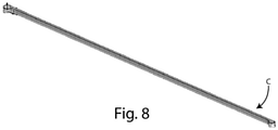
figure 8 shows the drive belt in detail. - In the various figures, similar parts will be indicated with the same numerical references.
- With reference to the figures, it is described a method for carrying a plurality of support elements, arranged on a bar B of a bar working table, and positioning each support element along said bar B in a respective predetermined position, corresponding to a desired position for each support element, in which said position is determined on the basis of the dimensions of the workpiece (such as for example a panel made of wood or another material) and/or of the type of machining.
- In fact, the bar working table is used for working one or more pieces P, in particular panels made of wood or another material.
- In the embodiment that is described, it will be made reference to a bar working table, of which only one bar B is visible.
- On said bar two support elements are arranged, i.e. a first support element S1 and a second support element S2.
- A
slider 2 is movable along a guide element G for carrying or dragging said first support element S1 and said second support element S2, and positioning each of said support elements along said bar B in a respective predetermined position (i.e. in a respective desired position). - The
slider 2 comprises abody 20 provided with a hookingelement 21 to be hooked/unhooked to/from a support element S1, S2. - In particular, the
slider 2 is movable between a rest position, in which said hookingelement 21 is unhooked from a support element S1, S2, and an operating position, in which said hookingelement 21 is hooked to a support element S1, S2. - More specifically, in the rest position, the hooking
element 21 is retracted inside thebody 20, and in the operating position, the hookingelement 21 has a protruding portion with respect to thebody 20 to be hooked to a support element S1, S2. - Each support element S1, S2 is provided with a respective recess S11, S21 to allow the hooking by the
slider 2, through said hookingelement 21. - Each recess S11, S21 is shaped to allow at least the partial insertion of said hooking
element 21. - As explained below, a motor (not shown) transmits the movement to the
slider 2 through a drive belt C. - A control logic (not shown) is connected to the motor and to the
slider 2 and configured to - ∘ operate said motor so that the
slider 2 slides along with the guide element G (by means of the movement of the drive belt C) and positions itself in a predetermined position along said guide element G so as to be positioned in correspondence with a support element (i.e. beneath said support element), - ∘ lift the hooking
element 21, when theslider 2 is in position (i.e. beneath said support element), so that saidslider 2 is hooked to said support element, - ∘ move said
slider 2, which said support element is hooked to, along with said guide element G so that said support element (moving along bar B) forms a row of support elements (composed of a plurality of support elements), and stops the movement of said support element in a desired position along the bar B associated with it or with a further support element of said row of support elements, - ∘ lower said hooking
element 21, when the support element is in position (i.e. in the desired position), so that saidslider 2 is unhooked from said support element and ready to be positioned in correspondence with a further hooking element, hook said further support element and carry the latter to the desired position. - When the
slider 2 is positioned in correspondence with a support element, saidslider 2 is positioned in such a way that said support element is overlapped or substantially overlapped on saidslider 2. - In particular, when the
slider 2 is positioned in correspondence with said first support element S1, saidslider 2 hooks said first support element S1 and carries said first support element S1 along the bar B until said first support element contacts a second support element S2, so that said two support elements (in contact with each other) form a row of support elements, in which the second support element S2 is arranged in succession to the first support element S1. - The number of support elements part of the row of support elements can increase if further support elements are arranged on the bar B and the
slider 2 continues to slide on the guide element G. - For example, if further support elements were arranged on the bar B and the
slider 2 continued to slide along the guide element G, the second support element S2 could contact a third support element, and said third support element could contact a fourth support element and so on, based on the number of support elements arranged on the bar B, so that also the number of support elements belonging to the row of support elements increases proportionally. - Consequently, by means of a
single slider 2, it is possible to position along the bar B one support element at a time, regardless of its position in the row of support elements that can be composed of any number of support elements. - In particular, it is possible to position on the bar B any of the support elements of the row of supporting elements first, regardless of its position in said row of support elements.
- For the sake of brevity in the embodiment that is described, two support elements S1, S2 are arranged on the bar B.
- Consequently, the method object of the invention provides that the
slider 2 hooks a first support element S1, slides along the bar B, so that said first support element S1 contacts a second support element S2, and a row of support elements composed of said two support elements S1, S2 is formed, and said row of support elements is carried along said bar B up to or said first support element S1 is positioned in a predetermined position with respect to said bar B (in which said predetermined position is a first desired position for said first support element S1), or said second support element S2 is positioned in a predetermined position with respect to said bar B (in which said predetermined position is a second desired position for said second support element S2 ). - When the first support element S1 has been positioned on the bar, the
slider 2 slides along with the guide element G until it is positioned in correspondence with the second support element S2, and hooks said second support element S2 for carrying it to a second desired position, associated with said second support element S2. - When the second support element S2 has been positioned on the bar, the
slider 2 slides along with the guide element G until it is positioned in correspondence with the first support element S1, and hooks said first support element S1 for carrying it to a first desired position, associated with said first support element S1. - In particular, this method comprises the following steps:
- A) providing a
slider 2 movable along with a guide element G, in which saidslider 2 comprises abody 20 provided with a hookingelement 21 for hooking a (single) support element S1, S2, where said hookingelement 21 is movable between a rest position, in which said hookingelement 21 is unhooked from said support element, and an operating position, in which said hookingelement 21 is hooked to said support element, - B) moving the
slider 2 along said guide element G, for positioning saidslider 2 in correspondence with a first support element S1, - C) when said
slider 2 is arranged in correspondence with said first support element S1, hooking said first support element S1 by saidslider 2, - D) moving along said guide element G said
slider 2 hooked to said first support element S1 for forming a row of support elements (i.e. so that on the bar B is formed a row of support elements, due to the movement of the first support element hooked to the slider), arranged in succession to each other, in which said row of support elements comprises at least a second support element S2, arranged in succession to said first support element S1, - E) carrying said row of support elements along said bar B up to a predetermined position, in which said predetermined position is the desired position of one (any) support element of said support row.
- In particular, said predetermined position can correspond to a first desired position for said first support element S1, and when said first support element S1 is positioned in said first desired position, said method can comprise the following steps:
- F1) unhooking the first support element S1 from said
slider 2, - G1) moving said
slider 2 along said guide element G to position saidslider 2 in correspondence with said second support element S2, - H1) when said
slider 2 is arranged in correspondence with said second support element S2, hooking said second support element S2 by saidslider 2, - 11) moving said
slider 2 along with said guide element G until said second support element S2 is positioned along said bar B in a second desired position for said second support element S2 (different from the first desired position for the first support S1). - Alternatively, said predetermined position can correspond to a second desired position for said second support element S2, and when said second support element S2 is positioned in said second desired position, said method comprises the following step:
F2) moving saidslider 2 along said guide element G until said first support element S1 is positioned along said bar B in a first desired position for said first support element S1 (different from the second desired position for said second support element support S2). - In such an alternative, after the step F2, the method can comprise a step G2, in which the first support element S1 is unhooked from said
slider 2. - With reference to the guide element G, said guide element G is connected to a side portion of said bar B.
- Although not shown in the figures, said guide element G can be connected to any portion of said bar B, different from said side portion.
- However, as already said, although not shown in the figures, the row of support elements carried along the bar B by the
slider 2 can be composed by any number of support elements (i.e. a number greater than two) and by means of asingle slider 2 it is possible to position a support element at a time along the bar B first, regardless of its position in the row of support elements. - In general, the step D can comprise the substep of moving said
slider 2 until said second support element contacts a third support element, and so on (i.e. said third support element contacts a fourth support element and said fourth support element support contacts a fifth support element, etc.), in such a way that said row of support elements comprises a number N of support elements arranged in succession, and the step E can comprise the substep of carrying said row of support elements along said bar B up to a predetermined position, in which said predetermined position is a desired position for any one of said N support elements. - Just to make an example referring to the presence of three support elements, the step D of the method can comprise the substep of moving said
slider 2 until said second support element S2 contacts a third support element, in such a way that said row of support elements comprises said third support element and said third support element is arranged in succession to said second support element S2. - Furthermore, the step E of the method can comprise the substep of carrying said row of support elements along said bar B up to a predetermined position, wherein said predetermined position is a predetermined first desired position for said first support element S1, or a predetermined second desired position for said second support element S2, or a predetermined third desired position for said third support element.
- With reference to the
slider 2, said slider can be provided with detection means for detecting the presence of a support element when saidslider 2 is positioned in correspondence with said support element (i.e. when theslider 2 is positioned in such a way that the support element is overlapped or substantially overlapped thereto). - Said detection means can comprise an optical proximity sensor, or an inductive proximity sensor, or a magnetic proximity sensor, or a capacitive proximity sensor, or an ultrasonic proximity sensor, or a radar.
- Furthermore, said
slider 2 can be provided with identification means for identifying the support element in correspondence with which saidslider 2 is positioned. - This allows knowing if the
slider 2 is positioned in correspondence with the desired support element. - In other words, it is possible to know if the position of the slider is correct with respect to the support element to be hooked.
- In a variant, said identification means can comprise a RFID reader arranged on said
slider 2, and a transponder arranged on each support element. - In a second variant, said identification means can comprise a reader arranged on said
slider 2 and a QR code arranged on each support element. - With reference to the
figures 6 - 8 , and in particular tofigures 7 and8 , the figures show the guide element G, on which saidslider 2 slides and the drive belt C, by means of which a motion is transmitted to saidslider 2 by means of a motor (not shown), in particular an electric motor. - Consequently, when the drive belt C is moved by said motor, the
slider 2 slides on said guide element G, until a predetermined position along said guide element G. corresponding to a desired position. - However, it is not necessary that the motion to the
slider 2 is imparted by means of a drive belt C. - For example, the motion to the
slider 2 can be imparted through any motion transmission system, such as, for example, a pinion-rack type transmission system, without departing from the scope of the invention. - A first advantage of the method object of the present invention is due to the fact that by means of a single slider it is possible to carry a row of support elements along a bar of a bar working table and position each support element of said row of support elements along said bar, regardless of the position of the support element inside the row of support elements.
- The present invention has been described for illustrative but not limitative purposes, according to its preferred embodiments, but it is to be understood that modifications and/or changes can be introduced by those skilled in the art without departing from the relevant scope as defined in the enclosed claims.
Claims (11)
- Method for carrying a plurality of support elements (S1,S2) arranged on a bar (B) of a bar working table and for positioning each support element (S1, S2) along said bar (B), said method comprising the following steps:A) providing a slider (2) movable along a guide element (G) connected to said bar (B), wherein said slider (2) comprises a body (20) provided with a hooking element (21) to be hooked/unhooked to/from a support element (S1, S2) of said plurality of support elements (S1,S2), wherein said hooking element (21) is movable between a rest position, in which said hooking element (21) is unhooked from said support element (S1,S2), and an operating position, in which said hooking element (21) is hooked to said support element (S1,S2),B) moving along said guide element (G) the slider (2) to position said slider (2) in correspondence with a first support element (S1),C) when said slider (2) is arranged in correspondence with said first support element (S1), hooking said first support element (S1) by said slider (2),D) moving along said guide element (G) said slider (2) to which said first support element (S1) is hooked to form a row of support elements arranged in succession to each other, wherein said row of support elements comprises at least a second support element (S2) arranged in succession to said first support element (S1),E) carrying said row of support elements along said bar (B) up to a predetermined position, wherein said predetermined position is the desired position of a support element of said row of support elements.
- Method according to claim 1, characterized in that said predetermined position corresponds to a first desired position for said first support element (S1), and in that when said first support element (S1) is positioned in said first desired position, said method comprises the following steps:F1) unhooking the first support element (S1) from said slider (2), G1) moving along said guide element (G) said slider (2) to position said slider (2) in correspondence with said second support element (S2),H1) when said slider (2) is arranged in correspondence with said second support element (S2), hooking said second support element (S2) by said slider (2),11) moving along said guide element (G) said slider (2) until said second support element (S2) is positioned along said bar (B) in a second desired position for said second support element (S2).
- Method according to claim 1, characterized in that said predetermined position corresponds to a second desired position for said second support element (S2), and in that when said second support element (S2) is positioned in said second desired position, said method comprises the following steps:
F2) moving along said guide element (G) said slider (2) until said first support element (S1) is positioned along said bar (B) in a first desired position for said first support element (S1). - Method according to claim 1, characterized in thatstep D comprises the substep of moving said slider (2) until said second support element (S2) contacts a third support element and so on in such a way that said row of support elements comprises a number N of support elements arranged in succession, andstep E comprises the substep of carrying said row of support elements along said bar (B) up to a predetermined position, wherein said predetermined position is a desired position for one of said N support elements.
- Method according to any one of the previous claims, characterized in that said guide element (G) is connected to a portion of said bar (B), preferably a side portion.
- Method according to any one of the previous claims, characterized in that said slider (2) is connected to a drive belt (C) and said drive belt (C) is connected to a motor, so that the movement imparted by said motor to said drive belt (C) is transmitted to said slider (2) by means of said drive belt (C).
- Method according to any one of the previous claims, characterized in that in said rest position, said hooking element (21) is retracted inside the body (20) of said slider (2), and in said operating position, said hooking element (21) has a portion protruding with respect to said body (20) to be hooked to a support element (S1,S2).
- Method according to any one of the previous claims, characterized in that said slider (2) is provided with detection means for detecting the presence of a support element (S1, S2), when said slider (2) is positioned in correspondence with said support element (S1, S2).
- Method according to the previous claim, characterized in that said detection means comprise an optical proximity sensor or an inductive proximity sensor or a magnetic proximity sensor or a capacitive proximity sensor or an ultrasonic proximity sensor or a radar.
- Method according to any of the previous claims, characterized in that said slider (2) is provided with identification means for identifying the support element (S1, S2) in correspondence with which said slider (2) is positioned.
- Method according to the previous claim, characterized in that said identification means comprise an RFID reader arranged on said slider (2) and a transponder arranged on each support element (S1, S2), or a reader arranged on said slider (2) and a QR code arranged on each support element (S1, S2).
Applications Claiming Priority (1)
| Application Number | Priority Date | Filing Date | Title |
|---|---|---|---|
| IT102020000017566A IT202000017566A1 (en) | 2020-07-20 | 2020-07-20 | METHOD FOR TRANSPORTING AND POSITIONING A MULTIPLE SUPPORTING ELEMENTS ON A WORKTOP. |
Publications (2)
| Publication Number | Publication Date |
|---|---|
| EP3943232A1 true EP3943232A1 (en) | 2022-01-26 |
| EP3943232B1 EP3943232B1 (en) | 2025-06-25 |
Family
ID=72885863
Family Applications (1)
| Application Number | Title | Priority Date | Filing Date |
|---|---|---|---|
| EP21184656.3A Active EP3943232B1 (en) | 2020-07-20 | 2021-07-09 | Method for carrying and positioning a plurality of support elements on a working table |
Country Status (2)
| Country | Link |
|---|---|
| EP (1) | EP3943232B1 (en) |
| IT (1) | IT202000017566A1 (en) |
Citations (2)
| Publication number | Priority date | Publication date | Assignee | Title |
|---|---|---|---|---|
| DE102009017856B3 (en) * | 2009-04-17 | 2010-09-09 | Ima Klessmann Gmbh Holzbearbeitungssysteme | support means |
| DE102010053657A1 (en) * | 2009-12-23 | 2011-06-30 | Felder Kg | Displacement and positioning device |
Family Cites Families (1)
| Publication number | Priority date | Publication date | Assignee | Title |
|---|---|---|---|---|
| DE10109212B4 (en) * | 2001-02-26 | 2006-04-27 | Reichenbacher Hamuel Gmbh | Method for positioning carriage, workpiece clamping table and processing machine |
-
2020
- 2020-07-20 IT IT102020000017566A patent/IT202000017566A1/en unknown
-
2021
- 2021-07-09 EP EP21184656.3A patent/EP3943232B1/en active Active
Patent Citations (2)
| Publication number | Priority date | Publication date | Assignee | Title |
|---|---|---|---|---|
| DE102009017856B3 (en) * | 2009-04-17 | 2010-09-09 | Ima Klessmann Gmbh Holzbearbeitungssysteme | support means |
| DE102010053657A1 (en) * | 2009-12-23 | 2011-06-30 | Felder Kg | Displacement and positioning device |
Also Published As
| Publication number | Publication date |
|---|---|
| EP3943232B1 (en) | 2025-06-25 |
| IT202000017566A1 (en) | 2022-01-20 |
Similar Documents
| Publication | Publication Date | Title |
|---|---|---|
| EP2488333B1 (en) | An apparatus for cutting articles comprising a flat surface on which designs and/or writings are reproduced and a method for actuating the apparatus | |
| US10370195B2 (en) | Method for operating a long stator linear motor | |
| US2988237A (en) | Programmed article transfer | |
| EP3214024B1 (en) | Autonomous conveyor system | |
| KR20210122094A (en) | Conveying apparatus using linear motor and Operating method thereof | |
| EP3418834B1 (en) | Conveyor system method of operating a conveyor system and flow devices for use in such conveyor system | |
| US8344856B2 (en) | Position detecting system and cable unit | |
| EP1553000B1 (en) | Rail guided vehicle system | |
| CN109510406B (en) | Identification of secondary components when used in a linear motor based system | |
| EP3943232B1 (en) | Method for carrying and positioning a plurality of support elements on a working table | |
| US2958247A (en) | Pattern control positioning a work piece and a tool turret for automatic operation | |
| US9370849B2 (en) | Flexible manufacturing system | |
| US20050061195A1 (en) | Conveying device | |
| CN105252508A (en) | Double-station reciprocating motion type material table equipment | |
| EP3643466B1 (en) | Machine tool for machining panels and method | |
| US4658682A (en) | Method and device to move one or more clamp elements in an automatic sheet metal machining center | |
| US20160179083A1 (en) | Numerical controller | |
| CN110116417B (en) | Article holding device | |
| US20100114370A1 (en) | Conveyance apparatus | |
| CN116117184B (en) | Lathe control method and system | |
| KR102474188B1 (en) | Mulberry cotton manufacturing apparatus | |
| KR102007568B1 (en) | System and Method for Safe Driving of Crane | |
| KR20070079676A (en) | Unmanned vehicle driving system and control method | |
| US2961752A (en) | Installation for manufacturing contact spring assemblies | |
| CN104992314B (en) | A kind of coil warehouse management system based on less radio-frequency |
Legal Events
| Date | Code | Title | Description |
|---|---|---|---|
| PUAI | Public reference made under article 153(3) epc to a published international application that has entered the european phase |
Free format text: ORIGINAL CODE: 0009012 |
|
| STAA | Information on the status of an ep patent application or granted ep patent |
Free format text: STATUS: THE APPLICATION HAS BEEN PUBLISHED |
|
| AK | Designated contracting states |
Kind code of ref document: A1 Designated state(s): AL AT BE BG CH CY CZ DE DK EE ES FI FR GB GR HR HU IE IS IT LI LT LU LV MC MK MT NL NO PL PT RO RS SE SI SK SM TR |
|
| STAA | Information on the status of an ep patent application or granted ep patent |
Free format text: STATUS: REQUEST FOR EXAMINATION WAS MADE |
|
| 17P | Request for examination filed |
Effective date: 20220315 |
|
| RBV | Designated contracting states (corrected) |
Designated state(s): AL AT BE BG CH CY CZ DE DK EE ES FI FR GB GR HR HU IE IS IT LI LT LU LV MC MK MT NL NO PL PT RO RS SE SI SK SM TR |
|
| P01 | Opt-out of the competence of the unified patent court (upc) registered |
Effective date: 20230518 |
|
| GRAP | Despatch of communication of intention to grant a patent |
Free format text: ORIGINAL CODE: EPIDOSNIGR1 |
|
| STAA | Information on the status of an ep patent application or granted ep patent |
Free format text: STATUS: GRANT OF PATENT IS INTENDED |
|
| INTG | Intention to grant announced |
Effective date: 20250318 |
|
| RIC1 | Information provided on ipc code assigned before grant |
Ipc: B23Q 1/03 20060101AFI20250311BHEP |
|
| RIN1 | Information on inventor provided before grant (corrected) |
Inventor name: BERTUCCIOLI, ALESSANDRO |
|
| GRAS | Grant fee paid |
Free format text: ORIGINAL CODE: EPIDOSNIGR3 |
|
| GRAA | (expected) grant |
Free format text: ORIGINAL CODE: 0009210 |
|
| STAA | Information on the status of an ep patent application or granted ep patent |
Free format text: STATUS: THE PATENT HAS BEEN GRANTED |
|
| AK | Designated contracting states |
Kind code of ref document: B1 Designated state(s): AL AT BE BG CH CY CZ DE DK EE ES FI FR GB GR HR HU IE IS IT LI LT LU LV MC MK MT NL NO PL PT RO RS SE SI SK SM TR |
|
| REG | Reference to a national code |
Ref country code: GB Ref legal event code: FG4D |
|
| REG | Reference to a national code |
Ref country code: CH Ref legal event code: EP |
|
| REG | Reference to a national code |
Ref country code: DE Ref legal event code: R096 Ref document number: 602021032712 Country of ref document: DE |
|
| REG | Reference to a national code |
Ref country code: CH Ref legal event code: EP |
|
| REG | Reference to a national code |
Ref country code: IE Ref legal event code: FG4D |
|
| PG25 | Lapsed in a contracting state [announced via postgrant information from national office to epo] |
Ref country code: FI Free format text: LAPSE BECAUSE OF FAILURE TO SUBMIT A TRANSLATION OF THE DESCRIPTION OR TO PAY THE FEE WITHIN THE PRESCRIBED TIME-LIMIT Effective date: 20250625 |
|
| PGFP | Annual fee paid to national office [announced via postgrant information from national office to epo] |
Ref country code: DE Payment date: 20250708 Year of fee payment: 5 |
|
| REG | Reference to a national code |
Ref country code: LT Ref legal event code: MG9D |
|
| PG25 | Lapsed in a contracting state [announced via postgrant information from national office to epo] |
Ref country code: NO Free format text: LAPSE BECAUSE OF FAILURE TO SUBMIT A TRANSLATION OF THE DESCRIPTION OR TO PAY THE FEE WITHIN THE PRESCRIBED TIME-LIMIT Effective date: 20250925 Ref country code: GR Free format text: LAPSE BECAUSE OF FAILURE TO SUBMIT A TRANSLATION OF THE DESCRIPTION OR TO PAY THE FEE WITHIN THE PRESCRIBED TIME-LIMIT Effective date: 20250926 |
|
| PG25 | Lapsed in a contracting state [announced via postgrant information from national office to epo] |
Ref country code: BG Free format text: LAPSE BECAUSE OF FAILURE TO SUBMIT A TRANSLATION OF THE DESCRIPTION OR TO PAY THE FEE WITHIN THE PRESCRIBED TIME-LIMIT Effective date: 20250625 |
|
| PG25 | Lapsed in a contracting state [announced via postgrant information from national office to epo] |
Ref country code: HR Free format text: LAPSE BECAUSE OF FAILURE TO SUBMIT A TRANSLATION OF THE DESCRIPTION OR TO PAY THE FEE WITHIN THE PRESCRIBED TIME-LIMIT Effective date: 20250625 |
|
| PGFP | Annual fee paid to national office [announced via postgrant information from national office to epo] |
Ref country code: AT Payment date: 20251020 Year of fee payment: 5 |
|
| PG25 | Lapsed in a contracting state [announced via postgrant information from national office to epo] |
Ref country code: RS Free format text: LAPSE BECAUSE OF FAILURE TO SUBMIT A TRANSLATION OF THE DESCRIPTION OR TO PAY THE FEE WITHIN THE PRESCRIBED TIME-LIMIT Effective date: 20250925 |
|
| PG25 | Lapsed in a contracting state [announced via postgrant information from national office to epo] |
Ref country code: LV Free format text: LAPSE BECAUSE OF FAILURE TO SUBMIT A TRANSLATION OF THE DESCRIPTION OR TO PAY THE FEE WITHIN THE PRESCRIBED TIME-LIMIT Effective date: 20250625 |
|
| REG | Reference to a national code |
Ref country code: NL Ref legal event code: MP Effective date: 20250625 |
|
| PG25 | Lapsed in a contracting state [announced via postgrant information from national office to epo] |
Ref country code: NL Free format text: LAPSE BECAUSE OF FAILURE TO SUBMIT A TRANSLATION OF THE DESCRIPTION OR TO PAY THE FEE WITHIN THE PRESCRIBED TIME-LIMIT Effective date: 20250625 |
|
| PG25 | Lapsed in a contracting state [announced via postgrant information from national office to epo] |
Ref country code: PT Free format text: LAPSE BECAUSE OF FAILURE TO SUBMIT A TRANSLATION OF THE DESCRIPTION OR TO PAY THE FEE WITHIN THE PRESCRIBED TIME-LIMIT Effective date: 20251027 |
|
| PG25 | Lapsed in a contracting state [announced via postgrant information from national office to epo] |
Ref country code: IS Free format text: LAPSE BECAUSE OF FAILURE TO SUBMIT A TRANSLATION OF THE DESCRIPTION OR TO PAY THE FEE WITHIN THE PRESCRIBED TIME-LIMIT Effective date: 20251025 |
|
| PG25 | Lapsed in a contracting state [announced via postgrant information from national office to epo] |
Ref country code: SM Free format text: LAPSE BECAUSE OF FAILURE TO SUBMIT A TRANSLATION OF THE DESCRIPTION OR TO PAY THE FEE WITHIN THE PRESCRIBED TIME-LIMIT Effective date: 20250625 |
|
| PG25 | Lapsed in a contracting state [announced via postgrant information from national office to epo] |
Ref country code: CZ Free format text: LAPSE BECAUSE OF FAILURE TO SUBMIT A TRANSLATION OF THE DESCRIPTION OR TO PAY THE FEE WITHIN THE PRESCRIBED TIME-LIMIT Effective date: 20250625 |
|
| PG25 | Lapsed in a contracting state [announced via postgrant information from national office to epo] |
Ref country code: PL Free format text: LAPSE BECAUSE OF FAILURE TO SUBMIT A TRANSLATION OF THE DESCRIPTION OR TO PAY THE FEE WITHIN THE PRESCRIBED TIME-LIMIT Effective date: 20250625 |
|
| PG25 | Lapsed in a contracting state [announced via postgrant information from national office to epo] |
Ref country code: EE Free format text: LAPSE BECAUSE OF FAILURE TO SUBMIT A TRANSLATION OF THE DESCRIPTION OR TO PAY THE FEE WITHIN THE PRESCRIBED TIME-LIMIT Effective date: 20250625 |
|
| PG25 | Lapsed in a contracting state [announced via postgrant information from national office to epo] |
Ref country code: SK Free format text: LAPSE BECAUSE OF FAILURE TO SUBMIT A TRANSLATION OF THE DESCRIPTION OR TO PAY THE FEE WITHIN THE PRESCRIBED TIME-LIMIT Effective date: 20250625 |
|
| PG25 | Lapsed in a contracting state [announced via postgrant information from national office to epo] |
Ref country code: ES Free format text: LAPSE BECAUSE OF FAILURE TO SUBMIT A TRANSLATION OF THE DESCRIPTION OR TO PAY THE FEE WITHIN THE PRESCRIBED TIME-LIMIT Effective date: 20250625 |
|
| REG | Reference to a national code |
Ref country code: CH Ref legal event code: H13 Free format text: ST27 STATUS EVENT CODE: U-0-0-H10-H13 (AS PROVIDED BY THE NATIONAL OFFICE) Effective date: 20260224 |
|
| PG25 | Lapsed in a contracting state [announced via postgrant information from national office to epo] |
Ref country code: RO Free format text: LAPSE BECAUSE OF FAILURE TO SUBMIT A TRANSLATION OF THE DESCRIPTION OR TO PAY THE FEE WITHIN THE PRESCRIBED TIME-LIMIT Effective date: 20250625 Ref country code: LU Free format text: LAPSE BECAUSE OF NON-PAYMENT OF DUE FEES Effective date: 20250709 |
|
| REG | Reference to a national code |
Ref country code: BE Ref legal event code: MM Effective date: 20250731 Ref country code: DE Ref legal event code: R097 Ref document number: 602021032712 Country of ref document: DE |
|
| PG25 | Lapsed in a contracting state [announced via postgrant information from national office to epo] |
Ref country code: MC Free format text: LAPSE BECAUSE OF FAILURE TO SUBMIT A TRANSLATION OF THE DESCRIPTION OR TO PAY THE FEE WITHIN THE PRESCRIBED TIME-LIMIT Effective date: 20250625 |
|
| PG25 | Lapsed in a contracting state [announced via postgrant information from national office to epo] |
Ref country code: DK Free format text: LAPSE BECAUSE OF FAILURE TO SUBMIT A TRANSLATION OF THE DESCRIPTION OR TO PAY THE FEE WITHIN THE PRESCRIBED TIME-LIMIT Effective date: 20250625 |
|
| PG25 | Lapsed in a contracting state [announced via postgrant information from national office to epo] |
Ref country code: BE Free format text: LAPSE BECAUSE OF NON-PAYMENT OF DUE FEES Effective date: 20250731 |
|
| PG25 | Lapsed in a contracting state [announced via postgrant information from national office to epo] |
Ref country code: CH Free format text: LAPSE BECAUSE OF NON-PAYMENT OF DUE FEES Effective date: 20250731 |
|
| PLBE | No opposition filed within time limit |
Free format text: ORIGINAL CODE: 0009261 |
|
| STAA | Information on the status of an ep patent application or granted ep patent |
Free format text: STATUS: NO OPPOSITION FILED WITHIN TIME LIMIT |
|
| REG | Reference to a national code |
Ref country code: CH Ref legal event code: L10 Free format text: ST27 STATUS EVENT CODE: U-0-0-L10-L00 (AS PROVIDED BY THE NATIONAL OFFICE) Effective date: 20260507 |