EP3943006A1 - Sensor insertion device - Google Patents
Sensor insertion device Download PDFInfo
- Publication number
- EP3943006A1 EP3943006A1 EP20772637.3A EP20772637A EP3943006A1 EP 3943006 A1 EP3943006 A1 EP 3943006A1 EP 20772637 A EP20772637 A EP 20772637A EP 3943006 A1 EP3943006 A1 EP 3943006A1
- Authority
- EP
- European Patent Office
- Prior art keywords
- case
- lower case
- sensor
- upper case
- holder
- Prior art date
- Legal status (The legal status is an assumption and is not a legal conclusion. Google has not performed a legal analysis and makes no representation as to the accuracy of the status listed.)
- Granted
Links
Images











Classifications
-
- A—HUMAN NECESSITIES
- A61—MEDICAL OR VETERINARY SCIENCE; HYGIENE
- A61B—DIAGNOSIS; SURGERY; IDENTIFICATION
- A61B5/00—Measuring for diagnostic purposes; Identification of persons
- A61B5/145—Measuring characteristics of blood in vivo, e.g. gas concentration or pH-value ; Measuring characteristics of body fluids or tissues, e.g. interstitial fluid or cerebral tissue
- A61B5/1468—Measuring characteristics of blood in vivo, e.g. gas concentration or pH-value ; Measuring characteristics of body fluids or tissues, e.g. interstitial fluid or cerebral tissue using chemical or electrochemical methods, e.g. by polarographic means
- A61B5/1473—Measuring characteristics of blood in vivo, e.g. gas concentration or pH-value ; Measuring characteristics of body fluids or tissues, e.g. interstitial fluid or cerebral tissue using chemical or electrochemical methods, e.g. by polarographic means invasive, e.g. introduced into the body by a catheter
-
- A—HUMAN NECESSITIES
- A61—MEDICAL OR VETERINARY SCIENCE; HYGIENE
- A61B—DIAGNOSIS; SURGERY; IDENTIFICATION
- A61B5/00—Measuring for diagnostic purposes; Identification of persons
- A61B5/145—Measuring characteristics of blood in vivo, e.g. gas concentration or pH-value ; Measuring characteristics of body fluids or tissues, e.g. interstitial fluid or cerebral tissue
- A61B5/1468—Measuring characteristics of blood in vivo, e.g. gas concentration or pH-value ; Measuring characteristics of body fluids or tissues, e.g. interstitial fluid or cerebral tissue using chemical or electrochemical methods, e.g. by polarographic means
- A61B5/1486—Measuring characteristics of blood in vivo, e.g. gas concentration or pH-value ; Measuring characteristics of body fluids or tissues, e.g. interstitial fluid or cerebral tissue using chemical or electrochemical methods, e.g. by polarographic means using enzyme electrodes, e.g. with immobilised oxidase
-
- A—HUMAN NECESSITIES
- A61—MEDICAL OR VETERINARY SCIENCE; HYGIENE
- A61M—DEVICES FOR INTRODUCING MEDIA INTO, OR ONTO, THE BODY; DEVICES FOR TRANSDUCING BODY MEDIA OR FOR TAKING MEDIA FROM THE BODY; DEVICES FOR PRODUCING OR ENDING SLEEP OR STUPOR
- A61M25/00—Catheters; Hollow probes
- A61M25/01—Introducing, guiding, advancing, emplacing or holding catheters
- A61M25/02—Holding devices, e.g. on the body
-
- A—HUMAN NECESSITIES
- A61—MEDICAL OR VETERINARY SCIENCE; HYGIENE
- A61M—DEVICES FOR INTRODUCING MEDIA INTO, OR ONTO, THE BODY; DEVICES FOR TRANSDUCING BODY MEDIA OR FOR TAKING MEDIA FROM THE BODY; DEVICES FOR PRODUCING OR ENDING SLEEP OR STUPOR
- A61M37/00—Other apparatus for introducing media into the body; Percutany, i.e. introducing medicines into the body by diffusion through the skin
-
- A—HUMAN NECESSITIES
- A61—MEDICAL OR VETERINARY SCIENCE; HYGIENE
- A61B—DIAGNOSIS; SURGERY; IDENTIFICATION
- A61B2560/00—Constructional details of operational features of apparatus; Accessories for medical measuring apparatus
- A61B2560/02—Operational features
- A61B2560/0266—Operational features for monitoring or limiting apparatus function
- A61B2560/028—Arrangements to prevent overuse, e.g. by counting the number of uses
- A61B2560/0285—Apparatus for single use
-
- A—HUMAN NECESSITIES
- A61—MEDICAL OR VETERINARY SCIENCE; HYGIENE
- A61B—DIAGNOSIS; SURGERY; IDENTIFICATION
- A61B2562/00—Details of sensors; Constructional details of sensor housings or probes; Accessories for sensors
- A61B2562/24—Hygienic packaging for medical sensors; Maintaining apparatus for sensor hygiene
- A61B2562/247—Hygienic covers, i.e. for covering the sensor or apparatus during use
Definitions
- the present invention relates, for example, to a sensor insertion device for inserting a sensor unit for performing continuous blood glucose measurement into a human body.
- Patent Literature 1 Japanese Unexamined Patent Application Publication (Translation of PCT Application) No. 2015-509011
- the sensor base is held by the lower case, and the sensor insertion device is pushed down by pushing down the upper case covering the lower case from above.
- the sensor insertion device includes a lower case, an upper case, , a base holder, a needle holder and a needle holder raising mechanism.
- the lower case formed in a cylindrical shape has an upper opening at the upper end and a lower opening at the lower end.
- the upper case formed in a cylindrical shape has an opening at the lower end and is closed on the upper surface, which covers the outer periphery of the lower case from above so as to be movable downward.
- the base holder is disposed inside the lower case and holds a sensor base having a sensor unit.
- the needle holder is disposed above the base holder inside the lower case.
- the needle holder raising mechanism is disposed above the needle holder inside the lower case and/or the upper case.
- a holding mechanism is provided to the inner peripheral surface of the upper case and/or the outer peripheral surface of the lower case. The holding mechanism is configured to hold the upper case on the lower case in a state in which the upper case has been pushed down until the opening of the upper case hits the skin.
- the sensor insertion device includes a lower case, an upper case, an upper position holding portion, a base holder and a holding mechanism.
- the lower case formed in a cylindrical shape has openings at the upper and lower ends respectively.
- the upper case formed in a cylindrical shape has an opening at the lower end, which covers the outer periphery of the lower case from above.
- the upper position holding portion holds the upper case at a specific upper position with respect to the lower case and exposes the lower case from the upper case.
- the base holder pre-holds a sensor base having a sensor unit and is disposed inside the lower case, and releases the sensor base when the upper case is pushed down from the upper position with respect to the lower case.
- the holding mechanism holds the upper case on the lower case in a state in which the upper case has been pushed down until the opening of the upper case is at substantially the same position as the lower opening of the lower case.
- the user since the sensor base having the sensor unit is held by the base holder, the user does not have to attach the sensor unit to the sensor base.
- the sensor base When the upper case is pushed down, the sensor base is attached to the skin and the sensor unit is inserted into the user's body.
- the opening of the upper case is at substantially the same position as the lower opening of the lower case, and this state is maintained by the holding mechanism. It is readily apparent that the device has been used. Therefore, no attempt is made to use it again, and this greatly enhances work efficiency.
- the sensor insertion device is formed in a substantially cylindrical shape as an example.
- the “inner and outer directions” correspond to the radial direction of the sensor insertion device, the “inner peripheral side” is the side closer to the center in the radial direction, and the “outer peripheral side” is the side away from the center in the radial direction.
- the “up and down direction” corresponds to the axial direction of the sensor insertion device, and “below” refers to the direction toward the user's body when the sensor insertion device is used.
- FIGS. 1 and 2 are oblique views of the sensor insertion device 1 according to an embodiment.
- the sensor insertion device 1 comprises an upper case 2 and a lower case 7.
- a cap 3 is detachably joined to the upper case 2 from below, and the lower case 7 is covered by the cap 3.
- a gasket (not shown) is provided at the joint between the upper case 2 and the cap 3. This seals the interior of the upper case 2 and the cap 3, and allows this interior to be kept in a sterile state.
- the user removes the cap 3 from the upper case 2 to expose the lower case 7, presses the sensor insertion device 1 against the user's body 4, and moves the upper case 2 downward with respect to the lower case 7.
- this pressing causes the sensor base 5 to be remove from the lower case 7 and attached to the body 4.
- the sensor base 5 has a needle-shaped sensor unit 6 extending downward from the sensor base 5.
- the sensor unit 6 is inserted into the body 4.
- a transmitter 8 is attached to the sensor base 5 after the sensor base 5 has been attached to the body 4.
- the transmitter 8 constitutes a biological information measurement device together with the sensor base 5 and the sensor unit 6, but is not housed in the lower case 7.
- FIG. 5 is an exploded oblique view of the sensor insertion device 1
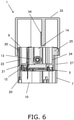
- FIG. 6 is a cross-sectional view of the sensor insertion device 1 in the state prior to use.
- the sensor insertion device 1 comprises a base holder 12, a needle holder 13, and a needle holder raising mechanism 14 in addition to the above-mentioned upper case 2, lower case 7, and sensor base 5.
- the lower case 7 is formed in a cylindrical shape having an upper opening 9 at its upper end and a lower opening 10 at its lower end.
- the upper case 2 is formed in a cylindrical shape having an opening 11 at its lower end and a closed upper surface.
- the upper case 2 is covered from above by the outer periphery of the lower case 7, and can move downward with respect to the lower case 7.
- the upper case 2 and the lower case 7 are disposed coaxially.
- the base holder 12 and the needle holder 13 are disposed inside the lower case 7.
- the base holder 12 and the needle holder 13 constitute a downward moving body that moves downward in the lower case 7 as the upper case 2 moves downward with respect to the lower case 7.
- the needle holder raising mechanism 14 is disposed inside the lower case 7 and/or the upper case 2. In the illustrated example, the needle holder raising mechanism 14 is disposed inside both cases 2 and 7, but this is only an example.
- the needle holder 13 is disposed above the base holder 12, and the needle holder raising mechanism 14 is disposed above the needle holder 13.
- FIGS. 7 and 8 show the lower case 7.
- the lower case 7 has one or more grooves 20 extending in the up and down direction on its inner peripheral surface. Furthermore, grooves 22 are formed inside the grooves 20.
- the grooves 20 and 22 extend downward from the upper opening 9 of the lower case 7.
- the lower case 7 has one or more slits 27 extending downward from the upper opening 9 of the lower case 7. In this embodiment, a plurality of slits 27 are disposed at equal intervals in the circumferential direction, and a plurality of grooves 20 are disposed at equal intervals in the circumferential direction.
- One of the grooves 20 is formed in the portion of the inner peripheral surface of the lower case 7 that is between slits 27 adjacent to each other in the circumferential direction.
- One of the slits 27 is formed between grooves 20 adjacent to each other in the circumferential direction.
- FIGS. 9 and 10 show the base holder 12.
- the base holder 12 has a top plate 15, a plurality of hanging pieces 16, a plurality of engaging pieces 17, a plurality of holding levers 18, a plurality of protrusions 19, and a plurality of protrusions 21.
- the top plate 15 is formed in an annular shape, for example.
- the plurality of hanging pieces 16 are disposed on the outer peripheral portion of the top plate 15 at equal intervals in the circumferential direction.
- the hanging pieces 16 extend downward from the outer peripheral portion of the top plate 15.
- the engaging pieces 17 and the holding levers 18 are respectively provided to the hanging pieces 16. Each engaging pieces 17 extends outward from the lower end of the corresponding hanging piece 16 and then rises upward.
- Each holding lever 18 extends in the circumferential direction from the side of the corresponding hanging piece 16.
- Each holding lever 18 is fixed to the base holder 12 at one end, and is freely displaceable in the inward and outward directions at the other end.
- the protrusions 19 are respectively provided to the holding levers 18.
- Each protrusion 19 is provided to the inner peripheral surface of the corresponding holding lever 18 (in particular, the displaceable other end portion).
- the protrusions 21 are respectively provided to the engaging pieces 17.
- Each protrusion 21 projects outward from the upper portion of the corresponding engaging piece 17.
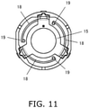
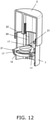
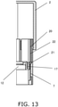
- FIGS. 11 to 13 show a state in which the base holder 12 has been attached to the lower case 7.
- the base holder 12 In mounting the base holder 12 on the lower case 7, the base holder 12 is inserted into the lower case 7 through the upper opening 9.
- the engaging pieces 17 are engaged with the grooves 20, and the protrusions 21 are engaged with the grooves 22.
- the base holder 12 is guided by the grooves 20 and 22 and moves downward in the lower case 7.
- the lower ends of the grooves 22 are located above the lower ends of the grooves 20. Therefore, when the protrusions 21 hit with the lower ends of the grooves 22, the downward movement of the lower case 7 stops.
- the base holder 12 At the time of attachment, that is, in the state prior to use, the base holder 12 is temporarily held in the lower case 7 at a standby position set in a middle portion in the lengthwise direction of the lower case 7.
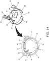
- FIGS. 14 and 15 show the base holder 12 in a state of being assembled with the sensor base 5.
- the sensor base 5 is pushed into the base holder 12 from below.
- the top plate 15 is positioned above the sensor base 5, and the hanging pieces 16 and the holding levers 18 are positioned on the outer periphery of the sensor base 5.
- Recesses 5a are provided to the outer peripheral portion of the sensor base 5 (see also FIG. 4 ).
- the sensor base 5 is held inside the base holder 12 when the protrusions 19 engage with the recesses 5a.
- the sensor base 5 is pre-held in the base holder 12 and is pre-housed in the lower case 7.
- At the stage of actually using the sensor insertion device 1 there is no need to attach the sensor base 5 to the sensor insertion device 1.
- the needle holder 13 has a top plate 23, a plurality of risers 24, a plurality of protrusions 25, and a plurality of restraining walls 26.
- the top plate 23 is formed in a substantially disk shape, for example.
- the risers 24 are disposed on the outer peripheral portion of the top plate 23 at equal intervals in the circumferential direction. Each riser 24 extends upward from the top plate 23.
- the protrusions 25 are respectively provided to the risers 24. Each protrusion 25 protrudes outward from the upper part of the corresponding riser 24.
- the restraining walls 26 hang downward from the top plate 23.
- the needle holder 13 In attaching the needle holder 13 to the lower case 7, the needle holder 13 is inserted into the lower case 7 through the upper opening 9. The protrusions 25 are engaged with the slits 27. The needle holder 13 is guided by the slits 27 and moves downward in the lower case 7. When the needle holder 13 hits the upper surface of the base holder 12 and the protrusions 21 of the base holder 12 hit the lower ends of the grooves 22, the downward movement of the needle holder 13 also stops. As a result, the needle holder 13 is mounted on the base holder 12 and is temporarily held along with the base holder 12 in the lower case 7.
- the protrusions 21 and the grooves 22 constitute a standby position setting unit that holds the base holder 12 and the needle holder 13 in a standby position at the time of mounting, that is, prior to use.
- the protrusions 25 are located at the upper part of the slits 27.
- FIGS. 16 and 17 show a state in which the needle holder 13 has been mounted on the base holder 12.
- the restraining walls 26 are disposed on the outer periphery of the holding levers 18, and the holding levers 18 cannot be displaced outward.
- the protrusions 19 are held in a state of being engaged with the recesses 5a of the sensor base 5. This prevents the sensor base 5 from accidentally falling downward.
- the needle holder 13 holds the guide needle 28.
- the guide needle 28 extends downward from the needle holder 13 and is inserted into the base holder 12 and the sensor base 5 to include the sensor unit 6.
- the shape of the guide needle 28 and the structure so that the guide needle 28 will include the sensor unit 6 will be described below with reference to FIGS. 27 and so forth.
- the needle holder 13 has an opening 29 formed in the top plate 23.
- the needle holder 13 has a rack 30 that is raised upward from the top plate 23 at a position adjacent to the opening 29.
- the rack 30 meshes with a pinion 32.
- the pinion 32 is provided on a rotating shaft 31 rotatably supported by the lower case 7.
- the rotating shaft 31 is oriented horizontally in the lower case 7 and is disposed higher than the (top plate 23 of the) needle holder 13.
- FIG. 18 is an exploded oblique view of the upper case 2 and the lower case 7.
- the upper case 2 has a top plate 33 that forms the upper surface.
- the upper case 2 has a rack 34 that is disposed in the upper case 2, extending downward from the lower surface of the top plate 33.
- the needle holder raising mechanism 14 is constituted by these racks 30 and 34 and the pinion 32.
- the rack 30 and the rack 34 are disposed so as to face each other in the radial direction of the rotating shaft 31 with the pinion 32 in between (see also FIGS. 19 to 22 ).
- the rack 34 is positioned so as to overlap the opening 29 in plan view (see FIG. 19 ).
- the upper case 2 has a plurality of engaging portions 35 and protrusions 39.
- the engaging portions 35 are provided to the lower part of the inner peripheral surface of the upper case 2, and are disposed at equal intervals in the circumferential direction.
- each engaging portion 35 is constituted by a groove extending upward from the opening 11 on the inner peripheral surface of the upper case 2.
- the two protrusions 39 are provided one above the other on the inner peripheral surface near the opening 11. A recess is formed between the two protrusions 39.
- the lower case 7 has protrusions 38 provided on its outer peripheral surface. The protrusions 38 are provided between the slits 27 at the upper part of the lower case 7.
- the portion of the peripheral wall of the lower case 7 where the protrusions 38 are disposed can flex in and out.
- the slits 27 extend downward from the opening 11 and terminate at a middle portion of the lower case 7 in the lengthwise direction.
- the portions of the slits 27 above the lower ends can flex, while the portions below the lower ends of the slits 27 are more resistant to flexing.
- the upper case 2 is attached to the lower case 7 in a state in which the base holder 12 and the needle holder 13 are being held in a standby state.
- the protrusions 25 of the needle holder 13 are engaged with the engaging portions 35.
- the opening 11 is covered by the upper opening 9 and the upper case 2 is pushed in, the lower of the two protrusions 39 hits the protrusions 38, and the peripheral wall of the lower case 7 flexes inward due to a wedge action.
- the peripheral wall of the lower case 7 is restored to its former state, and the protrusions 38 are latched in the recess between the two protrusions 39 (see FIG. 24 ).
- the protrusions 38 constitute an upper position setting unit for holding the upper case 2 in the upper position.
- the two protrusions 39 are provided so as to protrude in the inner peripheral direction from each of the upper and lower portions of the protrusions 38 in a state in which the upper case 2 is held in the upper position.
- FIGS. 19 to 22 show the operation when the sensor insertion device 1 is used.
- FIG. 23 is an oblique view of a used sensor insertion device 1.
- FIGS. 24 and 25 show detail views of the upper case 2 and the lower case 7, with FIG. 24 corresponding to FIG. 19 , and FIG. 25 corresponding to FIG. 21 .
- the lower opening 10 of the lower case 7 is brought into contact with the skin of the user's body 4.
- the base holder 12 and the needle holder 13 are held in the standby position, and the guide needle 28 is housed inside the cases 2 and 7, away from (above) the skin.
- the upper case 2 is pushed down with respect to the lower case 7.
- the protrusions 25 of the needle holder 13 are engaged with the engaging portions 35 of the upper case 2 through the slits 27. More precisely, the protrusions 25 are brought into contact with the upper ends of the groove-shaped engaging portions 35. Therefore, when the upper case 2 is pushed down, the protrusions 25 are pushed downward by the upper case 2, and the pressing force is transmitted through the needle holder 13 to the base holder 12. If the pressing force is strong enough, the hold of the upper case 2 by the upper position setting unit is released by wedge action, and the hold of the standby state by the standby position setting unit is also released.
- the upper case 2 moves downward from the upper position with respect to the lower case 7, and the base holder 12 and the needle holder 13 are pushed by the upper case 2 and move downward from the standby position.
- the protrusions 25 slide downward in the slits 27, and the downward motion of the needle holder 13 is guided by the slits 27.
- the rack 30 moves downward with respect to the pinion 32, and the pinion 32 and the rotating shaft 31 rotate in one direction (the counterclockwise direction in FIG. 19 ).
- the engaging pieces 17 slide downward in the grooves 20, and the downward motion of the base holder 12 is guided by the grooves 20.
- the grooves 20 extend further to the lower side of the lower case 7 than the slits 27. Therefore, the base holder 12 can move to the opening 10 of the lower case 7.
- the lower case 7 has a plurality of engaging portions 37.
- Each engaging portion 37 is provided in a concave shape at the lower end portion of the corresponding groove 20.
- the guide needle 28 and the sensor unit 6 contained therein are inserted into the body 4, and the lower surface of the sensor base 5 comes into contact with the body 4.
- a skin tape 36 (see FIG. 5 ) is provided on the lower surface of the sensor base 5.
- the sensor base 5 is attached to the body 4 by the adhesion of the skin tape 36.
- the opening 11 of the upper case 2 is located above the lower opening 10 of the lower case 7.
- the upper case 2 is further pushed down with respect to the lower case 7. If the pressing force is sufficient, the protrusions 25 and the engaging portions are disengaged, the upper case 2 moves downward, and the lower end of the rack 34 is engaged with the pinion 32. After this, the needle holder raising mechanism 14 comes into play.
- the rack 34 moves downward with respect to the pinion 32 in a state of being meshed with the pinion 32, and the pinion 32 is rotationally driven in the opposite direction (the clockwise direction in FIG. 20 ). Consequently, the rack 30 is moved in the opposite direction, that is, upward.
- the base holder 12 and the sensor base 5 remain unmoved with respect to the lower case 7, while the upper case 2 moves downward with respect to the lower case 7 and the needle holder 13 rises away from the base holder 12 in the lower case 7.
- the guide needle 28 rises together with the needle holder 13, is pulled out of the body 4, and is pulled up above the base holder 12.
- the rack 34 is inserted into the opening 29 formed in the top plate 33 of the needle holder 13, and the downward movement of the upper case 2 and the upward movement of the needle holder 13 are not hindered.
- the upper case 2 is pushed down until the opening 11 is at substantially the same position as the lower opening 10.
- the upper case 2 has a skin contact portion 2a that comes into contact with the skin of the body 4.
- the skin contact portion 2a is formed on the opening edge of the opening 11, or in other words, on the portion of the lower end of the upper case 2 that faces the body 4.
- the upper case 2 is pushed down until the skin contact portion 2a comes into contact with the skin.
- the guide needle 28 is pulled up into the lower case 7, and the guide needle 28 is covered from below by the base holder 12.
- the lower case 7 is in a state of being completely housed within the upper case 2.
- the sensor insertion device 1 also comprises a holding mechanism for holding the upper case 2 on the lower case 7 in a state in which the upper case 2 has been pushed down until the skin contact portion 2a comes into contact with the skin.
- the protrusions 39 of the upper case 2 are pressed against the lower end of the outer peripheral surface of the lower case 7 as the upper case 2 moves downward from the upper position with respect to the lower case 7. Since the lower end of the peripheral wall of the lower case 7 is lower than the lower end of the slit 27, this pressing can be withstood with almost no deformation. Consequently, the protrusions 39 of the upper case 2 and the portion of the lower case 7 that engages with the protrusions 39 constitute a holding mechanism for holding the upper case 2 on the lower case 7.
- the protrusions 25 of the needle holder 13 can also contribute to holding.
- the protrusions 25 of the needle holder 13 are pushed from the upper end of the engaging portions 35 of the upper case 2, and the needle holder 13 moves downward.
- the needle holder 13 begins to rise, at which point the protrusions 25 and the engaging portions 35 are disengaged.
- the risers 24 are elastically deformed inward, and the protrusions 25 engage with the inner peripheral surface of the upper case 2 under the elastic force of the risers 24.
- the protrusions 25 engage with the upper end portion of the inner peripheral surface of the upper case 2.
- the needle holder 13 is engaged with the lower case 7 via the rack 30, the pinion 32, and the rotating shaft 31. Consequently, the protrusions 25 of the needle holder 13 and the portion of the upper case 2 that engages with the protrusions 25 also constitute a holding mechanism for holding the upper case 2 on the lower case 7.
- the protrusions constituting the holding mechanism need not be provided to the upper case 2 or the lower case 7 itself, and may instead be provided to a member that is engaged with the upper case 2 or the lower case 7.
- the holding mechanism may be constituted by protrusions provided on the outer peripheral surface of the lower case 7 and engaging portions that are provided on the inner peripheral surface of the upper case 2 and engage with these protrusions.
- the restraining walls 26 of the needle holder 13 rise away from the holding levers 18 of the base holder 12, and the other ends of the holding levers 18 can be displaced outward. Therefore, the protrusions 19 move away from the recesses 5a in the sensor base 5, and the sensor base 5 is released from the base holder 12.
- the sensor base 5 remains attached to the body 4. Meanwhile, the base holder 12 covers the lower opening 10 of the lower case 7.
- the guide needle 28 is housed inside the cases 2 and 7, is hidden by the base holder 12, and is in an unexposed state. This prevents the guide needle 28 from touching the user's hand, and ensures that a used sensor insertion device 1 will be safe.
- the upper case 2 is held on the lower case 7 in a state in which the opening 11 of the upper case 2 is at substantially the same position as the lower opening 10 of the lower case 7, or in other words, a state in which the lower case 7 is completely housed in the upper case 2.
- the user can thus look at the sensor insertion device 1 held in this way and can tell at a glance that the device has been used. As a result, the user will not attempt to use the sensor insertion device 1 again, which makes the work much more efficient.
- the lower case 7 is provided with the slits 27. Since a movable portion is provided to the lower case 7, the upper case 2 can be more rigid. The user can firmly grasp the upper case 2. Also, the cylindrical portion of the upper case 2 is thicker than the cylindrical portion of the lower case 7 (see FIG. 23 ). This also provides greater rigidity to the upper case 2.
- FIGS. 28 to 30 show the guide needle 28.
- the guide needle 28 is formed, for example, by working a single sheet of material.
- the guide needle 28 has an attachment portion 40 and a body insertion portion 41.
- the attachment portion 40 is formed at the upper portion of the guide needle 28, and the body insertion portion 41 is formed at the lower portion of the guide needle 28.
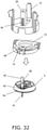
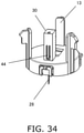
- FIGS. 31 to 34 show the procedure for mounting the guide needle 28.
- the guide needle 28 is held in an upright orientation by a holding jig (not shown).
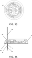
- the guide needle 28 is inserted into a first through-hole 42 in the sensor base 5 (see FIGS. 31 , 35, and 36 ).
- the sensor unit 6 is included in the guide needle 28. This inclusion will be described below.
- the guide needle 28 is inserted into a second through-hole 48 formed in the top plate 15 of the base holder 12 (see FIGS. 32 , 37, and 38 ). At this point, the sensor base 5 is held by the base holder 12.
- the base holder 12 must be positioned in the circumferential direction with respect to the sensor base 5 so that the first through-hole 42 is aligned with the second through-hole 48 in the up and down direction. As discussed above, the protrusions 19 of the base holder 12 engage with the recesses 5a of the sensor base 5. Consequently, at the same time as the holding of the sensor base 5, the base holder 12 is positioned, the through-holes 42 and 48 are aligned with each other, and the guide needle 28 is inserted into the sensor base 5 and the base holder 12.
- the attachment portion 40 of the guide needle 28 protrudes upward from the base holder 12 (see FIG. 33 ).
- the needle holder 13 has a holding portion 44 that holds the guide needle 28.
- the needle holder 13 has a columnar portion that protrudes upward from the top plate 33 in order to form the teeth of the rack 30.
- the holding portion 44 is provided to the columnar portion by utilizing the surface of the rack 30 on the opposite side from the teeth.
- the holding portion 44 has a push-in hole 45 that extends in the up and down direction inside the columnar portion and opens at least downward, and a protrusion 47 that protrudes from the inner surface of the push-in hole 45.
- the attachment portion 40 of the needle holder 13 is pushed into the push-in hole 45 from below. This results in the engagement of the protrusion 47 with a mounting hole 46 of the needle holder 13. This completes the mounting of the guide needle 28.
- the needle holder 13 must be positioned in the circumferential direction with respect to the base holder 12 so that the second through-hole 48 is aligned with the holding portion 44 in the up and down direction.
- the needle holder 13 therefore has a protrusion 49 that protrudes downward from the lower surface of the top plate 23 (see FIG. 14 ).
- the protrusion 49 is thrust into the second through-hole 48, this positions the needle holder 13 and aligns the second through-hole 48 with the holding portion 44.
- the positional relation between the body insertion portion 41 of the guide needle 28 and the lower insertion portion 6a of the sensor unit 6 (as shown in FIG. 36 , the portion that is provided on the lower end side of the sensor unit 6 and is inserted into the body 4).
- the attachment portion 40 of the guide needle 28 is provided with a pair of engaging pieces 50 formed by cutting and lifting.
- the engaging pieces 50 are disposed between the mounting hole 46 and the body insertion portion 41.
- the engaging pieces 50 are in contact with the first through-hole 42.
- the end face of the guide needle 28 in the width direction is also in contact with the first through-hole 42. This positions the guide needle 28 with respect to the sensor base 5.
- the sensor unit 6 is installed in a state of being positioned on the sensor base 5. Therefore, the guide needle 28 is positioned with respect to the sensor unit 6 via the sensor base 5.
- the sensor base 5 is installed with respect to the guide needle 28 from above the guide needle 28, as shown in FIG. 31 .
- the sensor unit 6 is inserted into the guide needle 28, and the state in which the sensor unit 6 is viewed from the sensor unit 6 side will be described with reference to FIGS. 47 to 49 .
- FIG. 47 shows a state in which the guide needle 28 is held upright by a holding jig (not shown).
- FIG. 48 shows a state in which the sensor base 5 is installed from above the guide needle 28.
- FIG. 48 shows a state in which the sensor unit 6 is lowered while the lower insertion portion 6a of the sensor unit 6 is in contact with the sliding attachment portion 40 of the guide needle 28.
- FIG. 49 shows a state in which the installation of the sensor unit 6 is complete, that is, a state in which the sensor base 5 has been installed on the guide needle 28 as shown in FIG. 32 .
- the body insertion portion 41 of the guide needle 28 does not touch the sensor unit 6, and in particular the lower insertion portion 6a, during the work of installing the guide needle 28. Since the distal end of the body insertion portion 41 of the guide needle 28 has a pointed shape, the sensor unit 6 may be damaged by just touching it slightly.
- the lower insertion portion 6a of the sensor unit 6 is installed in the body insertion portion 41 of the guide needle 28 from the sliding attachment portion 40, which is on the opposite side of the guide needle 28 from the body insertion portion 41.
- the sensor unit 6 will not be damaged by the body insertion portion 41 of the guide needle 28 during the installation work.
- the length of the guide surface 51 on the sliding attachment portion 40 of the guide needle 28 (the flat surface provided between the mounting hole 46 and the body insertion portion 41 in the sliding attachment portion 40) is greater than the length of the lower insertion portion in the sensor unit 6.
- the lower insertion portion of the sensor unit 6 is guided to the guide surface 51, and can be smoothly installed in the body insertion portion 41.
- the body insertion portion 41 of the guide needle 28 will now be described.
- the guide needle 28 has the sliding attachment portion 40 above and the body insertion portion 41 below.
- the body insertion portion 41 has a U-shaped cross section that is perpendicular to the lengthwise direction. Standing wall end portions 41a rise up on both sides of this U-shaped portion.
- an end face 41b in which the height of the standing wall end portion 41a of the U-shaped portion continuously decreases toward the lower end, and a distal end portion 41c constituted by the bottom surface of the U-shaped portion are provided on the lower end side of the body insertion portion 41.
- the distal end portion of the body insertion portion 41 has a pointed tip shape in which the cross-sectional area continuously decreases from the U-shaped portion toward the lower end, and a continuous edged portion 52 is formed on this pointed tip portion. That is, the continuous edged portion 52 is formed from the end face 41b portion to the distal end portion 41c.
- the standing wall end portion 41a of the U-shaped portion is ground from the outside of the U-shaped portion, and edging is continuously performed to produce a sharp blade all the way to the distal end (lower end).
- the guide needle of the conventional example only the distal end portion of the lower end portion is edged, and the upper end surface portion thereof is not. Therefore, the end face 41b portion of the standing wall end portion 41a of the U-shaped portion is recognized as a step, and this tended to cause pain.
- the guide needle 28 is such that the continuous edged portion 52 is formed, as shown in FIGS. 42 to 44 , on the portion near the lower end side of the guide needle 28, in the U-shaped portion formed for accommodating the sensor unit 6. More precisely, the continuous edged portion 52 is formed on the portion facing the skin, that is, the end face 41b portion and the distal end portion 41c, with respect to the skin of the body 4 approaching from the lower end side.
- the sensor insertion device 1 of this embodiment comprises the cylindrical lower case 7 and the upper case 2 that movably covers the outer periphery of the lower case 7 from above.
- the lower case 7 is formed in a cylindrical shape having the openings 9 and 10 on its upper and lower surfaces, respectively.
- the upper case 2 is formed in a cylindrical shape having the opening 11 on its lower surface and closed on its upper surface.
- the base holder 12 and the needle holder 13 are disposed in that order, from the bottom to the top, inside the lower case 7.
- the needle holder raising mechanism 14 (rack 30, pinion 32, rack 34) is disposed in the lower case 7 above the needle holder 13, and/or in the upper case 2 .
- the base holder 12 holds the sensor base 5, which has the sensor unit 6.
- the base holder 12 and the needle holder 13 move to the lower opening 10 side on the lower surface side of the lower case 7.
- the needle holder 13 rises, and the upper case 2 is pushed down until the opening 11 on the lower surface side thereof comes into contact with the skin of the body 4, and in this state the upper case 2 is held by the holding mechanism (the protrusions 39 and the outer peripheral wall portion below the slits 27 of the lower case 7) of the lower case 7).
- the base holder 12 holds the sensor base 5 having the sensor unit 6. Therefore, there is no need to attach the sensor unit 6 to the sensor base 5. Furthermore, when the upper case 2 is pushed down, the sensor base 5 is attached to the skin and the sensor unit 6 is inserted into the body 4.
- the opening 11 on the lower surface side of the upper case 2 and the lower opening 10 on the lower surface side of the lower case 7 are in substantially the same position. Consequently, it can be determined at a glance that the device has been used. Therefore, no one will try to use the sensor insertion device 1 again, and the work is much more efficient.
- the protrusions 39 are formed on the lower inner peripheral surface of the upper case 2, and the outer peripheral wall portion below the slits 27 of the lower case 7 is set as a portion facing the protrusions 39.
- the holding mechanism may be configured such that, for example, the protrusions 39 are provided on the lower outer peripheral surface of the lower case 7 and are brought into contact with the lower inner peripheral surface of the upper case 2.
- a mechanism for guiding the downward movement of the sensor base is provided to the lower case, and a mechanism for guiding the downward movement of the needle holder is provided to the upper case.
- the sensor base and the needle holder are guided by the corresponding guide mechanism as they move downward.
- an appropriate clearance is required between the upper and lower cases. Because of this clearance, there may be some looseness between the upper case may and the lower case. If the two guide mechanisms are divided into upper and lower cases as in the conventional example, the looseness may cause misalignment between the guide direction of the needle holder and the guide direction of the sensor base, and the needle holder and/or the sensor base may not move down properly. In this happens, the sensor base may not be properly attached to the skin, or the sensor unit may not be properly inserted into the body.
- the sensor insertion device 1 in this embodiment comprises the cylindrical lower case 7 and the upper case 2 movably covers the outer periphery of the lower case 7 from above.
- the lower case 7 has a cylindrical shape with the openings 9 and 10 on its upper and lower surfaces.
- the upper case 2 has a cylindrical shape with an opening 11 in the lower surface and a closed upper surface.
- the base holder 12 and the needle holder 13 are disposed in that order, from the bottom to the top.
- the needle holder raising mechanism 14 is disposed in the upper case 2 and/or the lower case 7 above the needle holder 13.
- the base holder 12 holds the sensor base 5 having the sensor unit 6.
- the lower case 7 is provided with the grooves 20 and the slits 27 as guiding means for guiding the downward motion of the base holder 12 and the needle holder 13.
- the base holder 12 can be guided by the grooves 20 while moving downward, and the needle holder 13 can be guided by the slits 27 while moving up and down.
- the sensor base 5 is properly attached to the body 4 and the sensor unit 6 is properly inserted into the body 4. That is, the needle holder 13 and the sensor base 5 having the sensor unit 6 are both moved downward by the guiding means provided to the lower case 7. Therefore, the positional relation between the sensor base 5 and the needle holder 13 during downward movement is stable. As a result, the sensor base 5 is properly attached to the body 4 and the sensor unit 6 is properly inserted into the body 4. Feature 3
- protrusions for holding the sensor base are provided to the lower case. The holding by these protrusions is released immediately after the upper case begins to move downward. Therefore, the sensor base may fall off of the sensor insertion device before the sensor base is attached to the body.
- the sensor insertion device 1 in this embodiment comprises the cylindrical lower case 7 and the upper case 2 that movably covers the outer circumference of the lower case 7 from above.
- the lower case 7 has a cylindrical shape with the openings 9 and 10 on its upper and lower surfaces.
- the upper case 2 has a cylindrical shape with an opening 11 in the lower surface and a closed upper surface.
- the needle holder raising mechanism 14 (rack 30, pinion 32, rack 34) is disposed in the upper case 2 and/or the lower case 7 above the needle holder 13.
- the base holder 12 has the holding levers 18 that are fixed at one end to the base holder 12 and are freely displaceable in the inward and outward directions at the other end, on the outer circumference of the sensor base 5.
- the protrusions 19 are formed that engage with the recesses 5a on the outer periphery of the sensor base 5.
- the needle holder 13 is provided with the restraining walls 26 that prevent the protrusions 19 of the holding levers 18 from moving outward on the outer peripheral portion of the base holder 12.
- the sensor base 5 is in a state of being held by the holding levers 18 of the base holder 12.
- the protrusions 19 of the holding levers 18 are prevented from moving outward by the restraining walls 26 provided to the needle holder 13.
- the sensor base 5 remains properly held by the base holder 12 until the sensor base 5 held by the base holder 12 is attached to the body 4, and the sensor unit 6 is inserted into the body 4 by the guide needle 28 of the needle holder 13. As a result, the sensor base 5 is prevented from being accidentally dropped before being attached to the body 4.
- the sensor unit is inserted into the body along with the guide needle.
- the tip of the guide needle is therefore extremely sharp.
- the sensor unit may be damaged. If this happens, the required measurement cannot be performed properly.
- the sensor insertion device 1 of this embodiment therefore comprises the cylindrical lower case 7 and the upper case 2 that movably covers the outer circumference of the lower case 7 from above.
- the lower case 7 has a cylindrical shape having openings 9 and 10 on its upper and lower surfaces.
- the upper case 2 has a cylindrical shape with the opening 11 on its lower surface and a closed upper surface.
- the needle holder raising mechanism 14 (rack 30, pinion 32, rack 34) is disposed in the upper case 2 and/or the lower case 7 above the needle holder 13.
- Through-holes 42 and 48 through which the guide needle 28 passes are formed in the sensor base 5 and the base holder 12.
- the holding portion 44 that holds the upper portion of the guide needle 28 is formed on the needle holder 13.
- the sensor base 5 and the base holder 12 are provided with a first positioning portion for aligning the through-holes 42 and 48 through which the guide needle 28 passes in the sensor base 5 and the base holder 12.
- the first positioning portion is configured such that the protrusions 19 of the base holder 12 engage with the recesses 5a on the outer periphery of the sensor base 5, and this is what aligns the through-hole 42 of the sensor base 5 with the through-hole 48 of the base holder 12.
- the base holder 12 and the needle holder 13 are provided with a second positioning portion for aligning the through-hole 48 of the base holder 12 with the holding portion 44 of the needle holder 13.
- the second positioning portion is configured to protrude downward toward the lower surface side of the top plate 23 of the needle holder 13, and to force the protrusion 49 into the through-hole 48 of the base holder 12 (see FIG. 30 ). That is, when the protrusion 49 of the needle holder 13 is forced into the through-hole 48 of the base holder 12, the through-hole 48 of the base holder 12 lines up with the holding portion 44 of the needle holder 13.
- the sensor base 5, the base holder 12, and the needle holder 13 are attached to the guide needle 28 from the upper part of the guide needle 28, they are held in the holding portion 44 of the needle holder 13.
- the sharp body insertion portion 41 will not damage the insertion portion of the sensor unit 6 at the lower part of the guide needle 28. As a result, an appropriate measurement can be made using the sensor unit 6.
- the sensor unit is included in the guide needle and is inserted into the body together with the guide needle.
- the tip of the guide needle is formed sharply so that it will be smoothly inserted into the body upon first touching the body, while the upper portion of the guide needle has a U-shaped cross section to include the guide needle.
- the U-shaped portion is also inserted into the body, but the end face of the plate forming the U-shaped portion creates a strong resistance to insertion, and this may cause the user to feel some pain.
- the sensor insertion device 1 of this embodiment comprises the cylindrical lower case 7 and the upper case 2 that movably covers the outer circumference of the lower case 7 from above.
- the lower case 7 has a cylindrical shape having openings 9 and 10 on its upper and lower surfaces.
- the upper case 2 has a cylindrical shape with the opening 11 on its lower surface and a closed upper surface.
- the needle holder raising mechanism 14 (rack 30, pinion 32, rack 34) is disposed in the upper case 2 and/or the lower case 7 above the needle holder 13.
- Through-holes 42 and 48 through which the guide needle 28 passes are formed in the sensor base 5 and the base holder 12.
- the needle holder 13 is formed with a holding portion 44 that holds the upper portion of the guide needle 28.
- the guide needle 28 has an upper sliding attachment portion 40 provided as an upward attachment portion, and a lower body insertion portion 41.
- the body insertion portion 41 has a U-shaped cross section that is perpendicular to the lengthwise direction.
- the distal end portion has a sharp tip shape in which the cross-sectional area decreases continuously from the U-shaped portion toward the lower end, and a continuous edged portion 52 is formed in the sharp tip portion.
- the guide needle 28 in this embodiment also has a U-shaped cross section that is perpendicular to the lengthwise direction in order to include the insertion portion of the sensor unit 6.
- the distal end portion has a sharp tip shape in which the cross-sectional area continuously decreases from the U-shaped portion toward the lower end, and the continuous edged portion 52 is formed in the sharp tip portion. Therefore, no strong resistance is produced when the body insertion portion 41 of the guide needle 28 is inserted into the body 4. As a result, the pain experienced by the user when the guide needle 28 is inserted can be reduced.
- the present invention can also be expressed as follows.
- a sensor insertion device comprising:
- the sensor insertion device according to addendum A1, wherein the guide mechanism has a groove (20) that extends in the up and down direction on the inner peripheral surface of the lower case, and an engaging piece (17) that slides in the groove 20 and is provided to the outer peripheral portion of the downward moving body.
- the sensor insertion device wherein the guide mechanism has a slit (27) that extends downward from the upper opening of the lower case, and a first protrusion (25) that slides in this slit and is provided to the outer peripheral portion of the downward moving body.
- the sensor insertion device wherein the guide mechanism has a plurality of slits (27) that extend downward from the upper opening of the lower case, and a groove (20) that extends in the up and down direction in the portion of the inner peripheral surface of the lower case that is between the slits in the circumferential direction.
- the sensor insertion device according to addendum A4, wherein the guide mechanism includes an engaging piece (17) that is provided on the outer peripheral portion of the base holder and engages with the groove, and a plurality of first protrusions (25) that are provided on the outer peripheral portion of the needle holder and engage with the plurality of slits.
- a sensor insertion device comprising:
- the sensor insertion device according to addendum B1, wherein the base holder has a plurality of the holding levers.
- a sensor insertion device comprising:
- the sensor insertion device according to addendum C2, wherein the attachment portion is provided with a guide surface for the sensor unit.
- a sensor insertion device comprising:
- the sensor insertion device according to addendum D1, wherein the sharp tip portion is formed by polishing the pair of standing wall end portions constituting the U-shaped portion from the outside.
- the present invention is expected to find widespread use as, for example, a sensor insertion device for inserting a sensor unit for performing continuous blood glucose measurement into a user's body.
Landscapes
- Health & Medical Sciences (AREA)
- Life Sciences & Earth Sciences (AREA)
- Physics & Mathematics (AREA)
- Engineering & Computer Science (AREA)
- Veterinary Medicine (AREA)
- Public Health (AREA)
- General Health & Medical Sciences (AREA)
- Animal Behavior & Ethology (AREA)
- Biomedical Technology (AREA)
- Heart & Thoracic Surgery (AREA)
- Medical Informatics (AREA)
- Biophysics (AREA)
- Chemical Kinetics & Catalysis (AREA)
- Molecular Biology (AREA)
- Surgery (AREA)
- Optics & Photonics (AREA)
- Pathology (AREA)
- General Chemical & Material Sciences (AREA)
- Chemical & Material Sciences (AREA)
- Anesthesiology (AREA)
- Hematology (AREA)
- Dermatology (AREA)
- Pulmonology (AREA)
- Measurement Of The Respiration, Hearing Ability, Form, And Blood Characteristics Of Living Organisms (AREA)
Abstract
Description
- The present invention relates, for example, to a sensor insertion device for inserting a sensor unit for performing continuous blood glucose measurement into a human body.
- Conventionally, when using this type of sensor insertion device, first, a sensor unit that is kept in a sterile state is attached to the sensor base of the sensor insertion device. After this, the sensor insertion device is pushed down toward the user's body. As a result, the sensor base is attached to the body and the sensor unit is inserted into the body (see, for example, Patent Literature 1).
- Patent Literature 1:
Japanese Unexamined Patent Application Publication (Translation of PCT Application) No. 2015-509011 - In the above-mentioned conventional example, the sensor base is held by the lower case, and the sensor insertion device is pushed down by pushing down the upper case covering the lower case from above.
- However, even if the upper case is pushed down, the lower part of the lower case is exposed below the upper case, just as it was before being pushed down, leaving the user unsure whether the sensor insertion device has already been used, and therefore the user may try to mount the sensor base again using this used sensor insertion device. However, with a used sensor insertion device, a new sensor unit cannot be attached to the sensor base, and if the sensor unit is allowed to stand for a long time during that period, the sterilization measures taken for the sensor unit will have been wasted, and the measurement reliability will end up decreasing. Thus, in the conventional example, it was difficult to determine whether or not the sensor insertion device had been used, which made it extremely inconvenient to use.
- It is therefore an object of the present invention to improve usage convenience of the sensor insertion device.
- The sensor insertion device according to an embodiment of the present invention includes a lower case, an upper case, , a base holder, a needle holder and a needle holder raising mechanism. The lower case formed in a cylindrical shape has an upper opening at the upper end and a lower opening at the lower end. The upper case formed in a cylindrical shape has an opening at the lower end and is closed on the upper surface, which covers the outer periphery of the lower case from above so as to be movable downward. The base holder is disposed inside the lower case and holds a sensor base having a sensor unit. The needle holder is disposed above the base holder inside the lower case. The needle holder raising mechanism is disposed above the needle holder inside the lower case and/or the upper case. When the upper case is pushed down, the base holder and the needle holder move toward the lower opening of the lower case. After this, the needle holder is raised by the needle holder raising mechanism. A holding mechanism is provided to the inner peripheral surface of the upper case and/or the outer peripheral surface of the lower case. The holding mechanism is configured to hold the upper case on the lower case in a state in which the upper case has been pushed down until the opening of the upper case hits the skin.
- The sensor insertion device according to another embodiment of the present invention includes a lower case, an upper case, an upper position holding portion, a base holder and a holding mechanism. The lower case formed in a cylindrical shape has openings at the upper and lower ends respectively. The upper case formed in a cylindrical shape has an opening at the lower end, which covers the outer periphery of the lower case from above. The upper position holding portion holds the upper case at a specific upper position with respect to the lower case and exposes the lower case from the upper case. The base holder pre-holds a sensor base having a sensor unit and is disposed inside the lower case, and releases the sensor base when the upper case is pushed down from the upper position with respect to the lower case. The holding mechanism holds the upper case on the lower case in a state in which the upper case has been pushed down until the opening of the upper case is at substantially the same position as the lower opening of the lower case.
- In the present invention, since the sensor base having the sensor unit is held by the base holder, the user does not have to attach the sensor unit to the sensor base. When the upper case is pushed down, the sensor base is attached to the skin and the sensor unit is inserted into the user's body. When the upper case is pushed down until its opening comes into contact with the skin, the opening of the upper case is at substantially the same position as the lower opening of the lower case, and this state is maintained by the holding mechanism. It is readily apparent that the device has been used. Therefore, no attempt is made to use it again, and this greatly enhances work efficiency.
-
-
FIG. 1 is an oblique view of the state before use of the sensor insertion device according to an embodiment; -
FIG. 2 is an oblique view of the sensor insertion device shown inFIG. 1 in a state in which a cap has been removed from the sensor insertion device; -
FIG. 3 is an oblique view of the usage state of the sensor insertion device inFIG. 2 ; -
FIG. 4 is an oblique view of a biological information measurement device used in the sensor insertion device inFIG. 2 ; -
FIG. 5 is an exploded oblique view of the sensor insertion device inFIG. 2 ; -
FIG. 6 is a cross-sectional view of the sensor insertion device inFIG. 2 ; -
FIG. 7 is an oblique view of the lower case of the sensor insertion device inFIG. 2 ; -
FIG. 8 is a plan view of the lower case of the sensor insertion device inFIG. 2 ; -
FIG. 9 is an oblique view of the base holder of the sensor insertion device inFIG. 2 ; -
FIG. 10 is a plan view of the base holder of the sensor insertion device inFIG. 2 ; -
FIG. 11 is a plan view of a state in which the base holder of the sensor insertion device inFIG. 2 has been attached to the lower case; -
FIG. 12 is an oblique view of the main components, illustrating the state inFIG. 11 ; -
FIG. 13 is a cross-sectional view of the main components, illustrating the state in FIG; -
FIG. 14 is an oblique view showing a state in which the sensor base is held by the base holder of the sensor insertion device inFIG. 2 , and a needle holder; -
FIG. 15 is a bottom view of the base holder and sensor base inFIG. 14 as viewed from below; -
FIG. 16 is an oblique view showing a state in which the needle holder inFIG. 14 has been attached to the base holder; -
FIG. 17 is a bottom view of the state inFIG. 16 as viewed from below; -
FIG. 18 is an exploded oblique view of the lower case and the upper case of the sensor insertion device inFIG. 2 ; -
FIG. 19 is a cross-sectional view of the operating state of the sensor insertion device inFIG. 2 ; -
FIG. 20 is a cross-sectional view of the operating state of the sensor insertion device inFIG. 2 ; -
FIG. 21 is a cross-sectional view of the operating state of the sensor insertion device inFIG. 2 ; -
FIG. 22 is a cross-sectional view of the operating state of the sensor insertion device inFIG. 2 ; -
FIG. 23 is an oblique view showing the used state of the sensor insertion device inFIG. 2 ; -
FIG. 24 is a cross-sectional view showing the relation between the lower case and the upper case of the sensor insertion device inFIG. 2 ; -
FIG. 25 is a cross-sectional view showing the relation between the lower case and the upper case of the sensor insertion device inFIG. 2 ; -
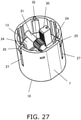
FIG. 26 is a cross-sectional view showing an example of the holding mechanism of the sensor insertion device inFIG. 2 ; -
FIG. 27 is an oblique view of the lower case, illustrating the state inFIG. 26 ; -
FIG. 28 is an oblique view of the guide needle of the sensor insertion device inFIG. 2 ; -
FIG. 29 is a front view of the guide needle of the sensor insertion device inFIG. 2 ; -
FIG. 30 is an oblique view of the guide needle of the sensor insertion device inFIG. 2 ; -
FIG. 31 is an oblique view of the procedure for mounting the guide needle of the sensor insertion device inFIG. 2 ; -
FIG. 32 is an oblique view of the procedure for mounting the guide needle of the sensor insertion device inFIG. 2 ; -
FIG. 33 is an oblique view of the procedure for mounting the guide needle of the sensor insertion device inFIG. 2 ; -
FIG. 34 is an oblique view of the procedure for mounting the guide needle of the sensor insertion device inFIG. 2 ; -
FIG. 35 is a plan view of the sensor base of the sensor insertion device inFIG. 2 ; -
FIG. 36 is a cross-sectional view of the sensor base of the sensor insertion device inFIG. 2 ; -
FIG. 37 is a detail cross-sectional view of the sensor base of the sensor insertion device inFIG. 2 ; -
FIG. 38 is a partially cutaway side view of the sensor base of the sensor insertion device inFIG. 2 ; -
FIG. 39 is a cross-sectional view of the sensor base, the base holder, and the needle holder of the sensor insertion device inFIG. 2 ; -
FIG. 40 is a partially enlarged cross-sectional view of the needle holder of the sensor insertion device inFIG. 2 ; -
FIG. 41 is a plan view of the guide needle of the sensor insertion device inFIG. 2 ; -
FIG. 42 is a detail plan view of the lower end portion of the guide needle of the sensor insertion device inFIG. 2 ; -
FIG. 43 is a cross-sectional view along the A-A line inFIG. 42 ; -
FIG. 44 is a detail front view of the lower end portion of the guide needle of the sensor insertion device inFIG. 2 ; -
FIG. 45 is a plan view of the guide needle of the sensor insertion device inFIG. 2 ; -
FIG. 46 is a cross-sectional view along the B-B line inFIG. 45 ; -
FIG. 47 is an oblique view of the guide needle of the sensor insertion device inFIG. 2 ; -
FIG. 48 is an oblique view of the guide needle of the sensor insertion device inFIG. 2 ; and -
FIG. 49 is an oblique view of the guide needle of the sensor insertion device inFIG. 2 . - Embodiments will now be described with reference to the appended drawings. In the drawings, the same or corresponding elements are numbered the same, and redundant description is omitted. The sensor insertion device according to an embodiment is formed in a substantially cylindrical shape as an example. The "inner and outer directions" correspond to the radial direction of the sensor insertion device, the "inner peripheral side" is the side closer to the center in the radial direction, and the "outer peripheral side" is the side away from the center in the radial direction. The "up and down direction" corresponds to the axial direction of the sensor insertion device, and "below" refers to the direction toward the user's body when the sensor insertion device is used.
-
FIGS. 1 and2 are oblique views of thesensor insertion device 1 according to an embodiment. As shown inFIG. 2 , thesensor insertion device 1 comprises anupper case 2 and alower case 7. As shown inFIG. 1 , prior to use, acap 3 is detachably joined to theupper case 2 from below, and thelower case 7 is covered by thecap 3. A gasket (not shown) is provided at the joint between theupper case 2 and thecap 3. This seals the interior of theupper case 2 and thecap 3, and allows this interior to be kept in a sterile state. - As shown in
FIGS. 2 and3 , in using thesensor insertion device 1, the user removes thecap 3 from theupper case 2 to expose thelower case 7, presses thesensor insertion device 1 against the user'sbody 4, and moves theupper case 2 downward with respect to thelower case 7. Referring toFIG. 4 , this pressing causes thesensor base 5 to be remove from thelower case 7 and attached to thebody 4. Thesensor base 5 has a needle-shapedsensor unit 6 extending downward from thesensor base 5. When thesensor base 5 is attached to thebody 4, thesensor unit 6 is inserted into thebody 4. Atransmitter 8 is attached to thesensor base 5 after thesensor base 5 has been attached to thebody 4. Thetransmitter 8 constitutes a biological information measurement device together with thesensor base 5 and thesensor unit 6, but is not housed in thelower case 7. -
FIG. 5 is an exploded oblique view of thesensor insertion device 1, andFIG. 6 is a cross-sectional view of thesensor insertion device 1 in the state prior to use. As shown inFIGS. 5 and6 , thesensor insertion device 1 comprises abase holder 12, aneedle holder 13, and a needleholder raising mechanism 14 in addition to the above-mentionedupper case 2,lower case 7, andsensor base 5. - The
lower case 7 is formed in a cylindrical shape having anupper opening 9 at its upper end and alower opening 10 at its lower end. Theupper case 2 is formed in a cylindrical shape having anopening 11 at its lower end and a closed upper surface. Theupper case 2 is covered from above by the outer periphery of thelower case 7, and can move downward with respect to thelower case 7. Theupper case 2 and thelower case 7 are disposed coaxially. - The
base holder 12 and theneedle holder 13 are disposed inside thelower case 7. Thebase holder 12 and theneedle holder 13 constitute a downward moving body that moves downward in thelower case 7 as theupper case 2 moves downward with respect to thelower case 7. The needleholder raising mechanism 14 is disposed inside thelower case 7 and/or theupper case 2. In the illustrated example, the needleholder raising mechanism 14 is disposed inside bothcases needle holder 13 is disposed above thebase holder 12, and the needleholder raising mechanism 14 is disposed above theneedle holder 13. -
FIGS. 7 and 8 show thelower case 7. As shown inFIGS. 5 to 8 , thelower case 7 has one ormore grooves 20 extending in the up and down direction on its inner peripheral surface. Furthermore,grooves 22 are formed inside thegrooves 20. Thegrooves upper opening 9 of thelower case 7. Thelower case 7 has one ormore slits 27 extending downward from theupper opening 9 of thelower case 7. In this embodiment, a plurality ofslits 27 are disposed at equal intervals in the circumferential direction, and a plurality ofgrooves 20 are disposed at equal intervals in the circumferential direction. One of thegrooves 20 is formed in the portion of the inner peripheral surface of thelower case 7 that is betweenslits 27 adjacent to each other in the circumferential direction. One of theslits 27 is formed betweengrooves 20 adjacent to each other in the circumferential direction. -
FIGS. 9 and 10 show thebase holder 12. Thebase holder 12 has atop plate 15, a plurality of hangingpieces 16, a plurality of engagingpieces 17, a plurality of holdinglevers 18, a plurality ofprotrusions 19, and a plurality ofprotrusions 21. Thetop plate 15 is formed in an annular shape, for example. The plurality of hangingpieces 16 are disposed on the outer peripheral portion of thetop plate 15 at equal intervals in the circumferential direction. The hangingpieces 16 extend downward from the outer peripheral portion of thetop plate 15. The engagingpieces 17 and the holding levers 18 are respectively provided to the hangingpieces 16. Each engagingpieces 17 extends outward from the lower end of the corresponding hangingpiece 16 and then rises upward. Each holdinglever 18 extends in the circumferential direction from the side of the corresponding hangingpiece 16. Each holdinglever 18 is fixed to thebase holder 12 at one end, and is freely displaceable in the inward and outward directions at the other end. Theprotrusions 19 are respectively provided to the holding levers 18. Eachprotrusion 19 is provided to the inner peripheral surface of the corresponding holding lever 18 (in particular, the displaceable other end portion). Theprotrusions 21 are respectively provided to the engagingpieces 17. Eachprotrusion 21 projects outward from the upper portion of the corresponding engagingpiece 17. -
FIGS. 11 to 13 show a state in which thebase holder 12 has been attached to thelower case 7. In mounting thebase holder 12 on thelower case 7, thebase holder 12 is inserted into thelower case 7 through theupper opening 9. The engagingpieces 17 are engaged with thegrooves 20, and theprotrusions 21 are engaged with thegrooves 22. Thebase holder 12 is guided by thegrooves lower case 7. The lower ends of thegrooves 22 are located above the lower ends of thegrooves 20. Therefore, when theprotrusions 21 hit with the lower ends of thegrooves 22, the downward movement of thelower case 7 stops. At the time of attachment, that is, in the state prior to use, thebase holder 12 is temporarily held in thelower case 7 at a standby position set in a middle portion in the lengthwise direction of thelower case 7. -
FIGS. 14 and15 show thebase holder 12 in a state of being assembled with thesensor base 5. As shown inFIGS. 6 ,14 , and15 , thesensor base 5 is pushed into thebase holder 12 from below. Thetop plate 15 is positioned above thesensor base 5, and the hangingpieces 16 and the holding levers 18 are positioned on the outer periphery of thesensor base 5.Recesses 5a are provided to the outer peripheral portion of the sensor base 5 (see alsoFIG. 4 ). Thesensor base 5 is held inside thebase holder 12 when theprotrusions 19 engage with therecesses 5a. Thus, at the point when thebase holder 12 is attached to thelower case 7, thesensor base 5 is pre-held in thebase holder 12 and is pre-housed in thelower case 7. At the stage of actually using thesensor insertion device 1, there is no need to attach thesensor base 5 to thesensor insertion device 1. - As shown in
FIGS. 5 ,6 , and14 , theneedle holder 13 has atop plate 23, a plurality ofrisers 24, a plurality ofprotrusions 25, and a plurality of restrainingwalls 26. Thetop plate 23 is formed in a substantially disk shape, for example. Therisers 24 are disposed on the outer peripheral portion of thetop plate 23 at equal intervals in the circumferential direction. Eachriser 24 extends upward from thetop plate 23. Theprotrusions 25 are respectively provided to therisers 24. Eachprotrusion 25 protrudes outward from the upper part of thecorresponding riser 24. The restrainingwalls 26 hang downward from thetop plate 23. - In attaching the
needle holder 13 to thelower case 7, theneedle holder 13 is inserted into thelower case 7 through theupper opening 9. Theprotrusions 25 are engaged with theslits 27. Theneedle holder 13 is guided by theslits 27 and moves downward in thelower case 7. When theneedle holder 13 hits the upper surface of thebase holder 12 and theprotrusions 21 of thebase holder 12 hit the lower ends of thegrooves 22, the downward movement of theneedle holder 13 also stops. As a result, theneedle holder 13 is mounted on thebase holder 12 and is temporarily held along with thebase holder 12 in thelower case 7. Theprotrusions 21 and thegrooves 22 constitute a standby position setting unit that holds thebase holder 12 and theneedle holder 13 in a standby position at the time of mounting, that is, prior to use. When theneedle holder 13 is being held in the standby position, theprotrusions 25 are located at the upper part of theslits 27. -
FIGS. 16 and17 show a state in which theneedle holder 13 has been mounted on thebase holder 12. As shown inFIGS. 16 and17 , when theneedle holder 13 is mounted on thebase holder 12, the restrainingwalls 26 are disposed on the outer periphery of the holding levers 18, and the holding levers 18 cannot be displaced outward. As a result, theprotrusions 19 are held in a state of being engaged with therecesses 5a of thesensor base 5. This prevents thesensor base 5 from accidentally falling downward. - The
needle holder 13 holds theguide needle 28. In the state prior to use, theguide needle 28 extends downward from theneedle holder 13 and is inserted into thebase holder 12 and thesensor base 5 to include thesensor unit 6. The shape of theguide needle 28 and the structure so that theguide needle 28 will include thesensor unit 6 will be described below with reference toFIGS. 27 and so forth. - As shown in
FIGS. 5 and6 , theneedle holder 13 has anopening 29 formed in thetop plate 23. Theneedle holder 13 has arack 30 that is raised upward from thetop plate 23 at a position adjacent to theopening 29. Therack 30 meshes with apinion 32. Thepinion 32 is provided on arotating shaft 31 rotatably supported by thelower case 7. The rotatingshaft 31 is oriented horizontally in thelower case 7 and is disposed higher than the (top plate 23 of the)needle holder 13. -
FIG. 18 is an exploded oblique view of theupper case 2 and thelower case 7. As shown inFIGS. 5 ,6 , and18 , theupper case 2 has atop plate 33 that forms the upper surface. Theupper case 2 has arack 34 that is disposed in theupper case 2, extending downward from the lower surface of thetop plate 33. The needleholder raising mechanism 14 is constituted by theseracks pinion 32. Therack 30 and therack 34 are disposed so as to face each other in the radial direction of therotating shaft 31 with thepinion 32 in between (see alsoFIGS. 19 to 22 ). In a state in which theupper case 2 is assembled to thelower case 7, therack 34 is positioned so as to overlap theopening 29 in plan view (seeFIG. 19 ). - As shown in
FIG. 18 , theupper case 2 has a plurality of engagingportions 35 andprotrusions 39. The engagingportions 35 are provided to the lower part of the inner peripheral surface of theupper case 2, and are disposed at equal intervals in the circumferential direction. In this embodiment, each engagingportion 35 is constituted by a groove extending upward from theopening 11 on the inner peripheral surface of theupper case 2. The twoprotrusions 39 are provided one above the other on the inner peripheral surface near theopening 11. A recess is formed between the twoprotrusions 39. Meanwhile, thelower case 7 hasprotrusions 38 provided on its outer peripheral surface. Theprotrusions 38 are provided between theslits 27 at the upper part of thelower case 7. The portion of the peripheral wall of thelower case 7 where theprotrusions 38 are disposed can flex in and out. Theslits 27 extend downward from theopening 11 and terminate at a middle portion of thelower case 7 in the lengthwise direction. The portions of theslits 27 above the lower ends can flex, while the portions below the lower ends of theslits 27 are more resistant to flexing. - The
upper case 2 is attached to thelower case 7 in a state in which thebase holder 12 and theneedle holder 13 are being held in a standby state. First, theprotrusions 25 of theneedle holder 13 are engaged with the engagingportions 35. When theopening 11 is covered by theupper opening 9 and theupper case 2 is pushed in, the lower of the twoprotrusions 39 hits theprotrusions 38, and the peripheral wall of thelower case 7 flexes inward due to a wedge action. When the lower of the twoprotrusions 39 rides up and over theprotrusions 38 and moves downward, the peripheral wall of thelower case 7 is restored to its former state, and theprotrusions 38 are latched in the recess between the two protrusions 39 (seeFIG. 24 ). This completes the attachment of theupper case 2 to thelower case 7, and theupper case 2 is held at a specific upper position. Theprotrusions 38 constitute an upper position setting unit for holding theupper case 2 in the upper position. The twoprotrusions 39 are provided so as to protrude in the inner peripheral direction from each of the upper and lower portions of theprotrusions 38 in a state in which theupper case 2 is held in the upper position. -
FIGS. 19 to 22 show the operation when thesensor insertion device 1 is used.FIG. 23 is an oblique view of a usedsensor insertion device 1.FIGS. 24 and 25 show detail views of theupper case 2 and thelower case 7, withFIG. 24 corresponding toFIG. 19 , andFIG. 25 corresponding toFIG. 21 . - As shown in
FIGS. 19 and24 , in using thesensor insertion device 1, thelower opening 10 of thelower case 7 is brought into contact with the skin of the user'sbody 4. At this point, thebase holder 12 and theneedle holder 13 are held in the standby position, and theguide needle 28 is housed inside thecases - Next, the
upper case 2 is pushed down with respect to thelower case 7. Theprotrusions 25 of theneedle holder 13 are engaged with the engagingportions 35 of theupper case 2 through theslits 27. More precisely, theprotrusions 25 are brought into contact with the upper ends of the groove-shapedengaging portions 35. Therefore, when theupper case 2 is pushed down, theprotrusions 25 are pushed downward by theupper case 2, and the pressing force is transmitted through theneedle holder 13 to thebase holder 12. If the pressing force is strong enough, the hold of theupper case 2 by the upper position setting unit is released by wedge action, and the hold of the standby state by the standby position setting unit is also released. - As shown in
FIG. 20 , theupper case 2 moves downward from the upper position with respect to thelower case 7, and thebase holder 12 and theneedle holder 13 are pushed by theupper case 2 and move downward from the standby position. Theprotrusions 25 slide downward in theslits 27, and the downward motion of theneedle holder 13 is guided by theslits 27. At this point, therack 30 moves downward with respect to thepinion 32, and thepinion 32 and therotating shaft 31 rotate in one direction (the counterclockwise direction inFIG. 19 ). Also, the engagingpieces 17 slide downward in thegrooves 20, and the downward motion of thebase holder 12 is guided by thegrooves 20. Thegrooves 20 extend further to the lower side of thelower case 7 than theslits 27. Therefore, thebase holder 12 can move to theopening 10 of thelower case 7. - The
lower case 7 has a plurality of engagingportions 37. Each engagingportion 37 is provided in a concave shape at the lower end portion of the correspondinggroove 20. When thebase holder 12 reaches the vicinity of thelower opening 10, theprotrusions 21 are forced into the corresponding engagingportions 37, resulting in engagement. Even if thebase holder 12 tries to move upward, theprotrusions 21 will hit the upper ends of the engagingportions 37, so this upward motion is restricted. - When the
base holder 12 moves to theopening 10, theguide needle 28 and thesensor unit 6 contained therein are inserted into thebody 4, and the lower surface of thesensor base 5 comes into contact with thebody 4. A skin tape 36 (seeFIG. 5 ) is provided on the lower surface of thesensor base 5. Thesensor base 5 is attached to thebody 4 by the adhesion of theskin tape 36. - When the
sensor base 5 comes into contact with thebody 4, theopening 11 of theupper case 2 is located above thelower opening 10 of thelower case 7. In view of this, theupper case 2 is further pushed down with respect to thelower case 7. If the pressing force is sufficient, theprotrusions 25 and the engaging portions are disengaged, theupper case 2 moves downward, and the lower end of therack 34 is engaged with thepinion 32. After this, the needleholder raising mechanism 14 comes into play. Therack 34 moves downward with respect to thepinion 32 in a state of being meshed with thepinion 32, and thepinion 32 is rotationally driven in the opposite direction (the clockwise direction inFIG. 20 ). Consequently, therack 30 is moved in the opposite direction, that is, upward. Thebase holder 12 and thesensor base 5 remain unmoved with respect to thelower case 7, while theupper case 2 moves downward with respect to thelower case 7 and theneedle holder 13 rises away from thebase holder 12 in thelower case 7. Theguide needle 28 rises together with theneedle holder 13, is pulled out of thebody 4, and is pulled up above thebase holder 12. Therack 34 is inserted into theopening 29 formed in thetop plate 33 of theneedle holder 13, and the downward movement of theupper case 2 and the upward movement of theneedle holder 13 are not hindered. - As shown in
FIGS. 21 and25 , theupper case 2 is pushed down until theopening 11 is at substantially the same position as thelower opening 10. Theupper case 2 has askin contact portion 2a that comes into contact with the skin of thebody 4. Theskin contact portion 2a is formed on the opening edge of theopening 11, or in other words, on the portion of the lower end of theupper case 2 that faces thebody 4. Theupper case 2 is pushed down until theskin contact portion 2a comes into contact with the skin. When theupper case 2 is properly pushed down in this way, theguide needle 28 is pulled up into thelower case 7, and theguide needle 28 is covered from below by thebase holder 12. Thelower case 7 is in a state of being completely housed within theupper case 2. - The
sensor insertion device 1 also comprises a holding mechanism for holding theupper case 2 on thelower case 7 in a state in which theupper case 2 has been pushed down until theskin contact portion 2a comes into contact with the skin. Theprotrusions 39 of theupper case 2 are pressed against the lower end of the outer peripheral surface of thelower case 7 as theupper case 2 moves downward from the upper position with respect to thelower case 7. Since the lower end of the peripheral wall of thelower case 7 is lower than the lower end of theslit 27, this pressing can be withstood with almost no deformation. Consequently, theprotrusions 39 of theupper case 2 and the portion of thelower case 7 that engages with theprotrusions 39 constitute a holding mechanism for holding theupper case 2 on thelower case 7. - Furthermore, as shown in
FIGS. 26 and27 , theprotrusions 25 of theneedle holder 13 can also contribute to holding. When theupper case 2 is pushed down, theprotrusions 25 of theneedle holder 13 are pushed from the upper end of the engagingportions 35 of theupper case 2, and theneedle holder 13 moves downward. While theupper case 2 is being pushed down, theneedle holder 13 begins to rise, at which point theprotrusions 25 and the engagingportions 35 are disengaged. Therisers 24 are elastically deformed inward, and theprotrusions 25 engage with the inner peripheral surface of theupper case 2 under the elastic force of therisers 24. When theskin contact portion 2a is in contact with the skin, theprotrusions 25 engage with the upper end portion of the inner peripheral surface of theupper case 2. Theneedle holder 13 is engaged with thelower case 7 via therack 30, thepinion 32, and therotating shaft 31. Consequently, theprotrusions 25 of theneedle holder 13 and the portion of theupper case 2 that engages with theprotrusions 25 also constitute a holding mechanism for holding theupper case 2 on thelower case 7. - Thus, the protrusions constituting the holding mechanism need not be provided to the
upper case 2 or thelower case 7 itself, and may instead be provided to a member that is engaged with theupper case 2 or thelower case 7. Also, the holding mechanism may be constituted by protrusions provided on the outer peripheral surface of thelower case 7 and engaging portions that are provided on the inner peripheral surface of theupper case 2 and engage with these protrusions. - As the
needle holder 13 rises, the restrainingwalls 26 of theneedle holder 13 rise away from the holding levers 18 of thebase holder 12, and the other ends of the holding levers 18 can be displaced outward. Therefore, theprotrusions 19 move away from therecesses 5a in thesensor base 5, and thesensor base 5 is released from thebase holder 12. - As shown in
FIGS. 22 and23 , when the pressing of theupper case 2 is completed and thesensor insertion device 1 is lifted upward from thebody 4, thesensor base 5 remains attached to thebody 4. Meanwhile, thebase holder 12 covers thelower opening 10 of thelower case 7. Theguide needle 28 is housed inside thecases base holder 12, and is in an unexposed state. This prevents theguide needle 28 from touching the user's hand, and ensures that a usedsensor insertion device 1 will be safe. - Furthermore, the
upper case 2 is held on thelower case 7 in a state in which theopening 11 of theupper case 2 is at substantially the same position as thelower opening 10 of thelower case 7, or in other words, a state in which thelower case 7 is completely housed in theupper case 2. The user can thus look at thesensor insertion device 1 held in this way and can tell at a glance that the device has been used. As a result, the user will not attempt to use thesensor insertion device 1 again, which makes the work much more efficient. - In this embodiment, the
lower case 7 is provided with theslits 27. Since a movable portion is provided to thelower case 7, theupper case 2 can be more rigid. The user can firmly grasp theupper case 2. Also, the cylindrical portion of theupper case 2 is thicker than the cylindrical portion of the lower case 7 (seeFIG. 23 ). This also provides greater rigidity to theupper case 2. - In the above example, there were three each of the
elements 16 to 22, 24 to 27, 35, and 37, but there is no particular restriction on the number of these elements. - Next, the
guide needle 28 will be described with reference toFIGS. 28 to 49 .FIGS. 28 to 30 show theguide needle 28. Theguide needle 28 is formed, for example, by working a single sheet of material. Theguide needle 28 has anattachment portion 40 and abody insertion portion 41. Theattachment portion 40 is formed at the upper portion of theguide needle 28, and thebody insertion portion 41 is formed at the lower portion of theguide needle 28. -
FIGS. 31 to 34 show the procedure for mounting theguide needle 28. First, theguide needle 28 is held in an upright orientation by a holding jig (not shown). Theguide needle 28 is inserted into a first through-hole 42 in the sensor base 5 (seeFIGS. 31 ,35, and 36 ). At this point, thesensor unit 6 is included in theguide needle 28. This inclusion will be described below. - Next, the
guide needle 28 is inserted into a second through-hole 48 formed in thetop plate 15 of the base holder 12 (seeFIGS. 32 ,37, and 38 ). At this point, thesensor base 5 is held by thebase holder 12. - The
base holder 12 must be positioned in the circumferential direction with respect to thesensor base 5 so that the first through-hole 42 is aligned with the second through-hole 48 in the up and down direction. As discussed above, theprotrusions 19 of thebase holder 12 engage with therecesses 5a of thesensor base 5. Consequently, at the same time as the holding of thesensor base 5, thebase holder 12 is positioned, the through-holes guide needle 28 is inserted into thesensor base 5 and thebase holder 12. - The
attachment portion 40 of theguide needle 28 protrudes upward from the base holder 12 (seeFIG. 33 ). Next, theguide needle 28 is held by the needle holder 13 (seeFIGS. 34 ,39, and 40 ). Theneedle holder 13 has a holdingportion 44 that holds theguide needle 28. Theneedle holder 13 has a columnar portion that protrudes upward from thetop plate 33 in order to form the teeth of therack 30. The holdingportion 44 is provided to the columnar portion by utilizing the surface of therack 30 on the opposite side from the teeth. The holdingportion 44 has a push-inhole 45 that extends in the up and down direction inside the columnar portion and opens at least downward, and aprotrusion 47 that protrudes from the inner surface of the push-inhole 45. Theattachment portion 40 of theneedle holder 13 is pushed into the push-inhole 45 from below. This results in the engagement of theprotrusion 47 with a mountinghole 46 of theneedle holder 13. This completes the mounting of theguide needle 28. - The
needle holder 13 must be positioned in the circumferential direction with respect to thebase holder 12 so that the second through-hole 48 is aligned with the holdingportion 44 in the up and down direction. Theneedle holder 13 therefore has aprotrusion 49 that protrudes downward from the lower surface of the top plate 23 (seeFIG. 14 ). When theprotrusion 49 is thrust into the second through-hole 48, this positions theneedle holder 13 and aligns the second through-hole 48 with the holdingportion 44. In order to produce this state, what is particularly important is the positional relation between thebody insertion portion 41 of theguide needle 28 and thelower insertion portion 6a of the sensor unit 6 (as shown inFIG. 36 , the portion that is provided on the lower end side of thesensor unit 6 and is inserted into the body 4). - In this embodiment, as shown in
FIG. 30 , theattachment portion 40 of theguide needle 28 is provided with a pair of engagingpieces 50 formed by cutting and lifting. The engagingpieces 50 are disposed between the mountinghole 46 and thebody insertion portion 41. As shown inFIGS. 36 and37 , the engagingpieces 50 are in contact with the first through-hole 42. As shown inFIG. 38 , the end face of theguide needle 28 in the width direction is also in contact with the first through-hole 42. This positions theguide needle 28 with respect to thesensor base 5. Meanwhile, thesensor unit 6 is installed in a state of being positioned on thesensor base 5. Therefore, theguide needle 28 is positioned with respect to thesensor unit 6 via thesensor base 5. - In order to produce the state shown in
FIGS. 35 to 38 , thesensor base 5 is installed with respect to theguide needle 28 from above theguide needle 28, as shown inFIG. 31 . At this point, thesensor unit 6 is inserted into theguide needle 28, and the state in which thesensor unit 6 is viewed from thesensor unit 6 side will be described with reference toFIGS. 47 to 49 . -
FIG. 47 shows a state in which theguide needle 28 is held upright by a holding jig (not shown).FIG. 48 shows a state in which thesensor base 5 is installed from above theguide needle 28.FIG. 48 shows a state in which thesensor unit 6 is lowered while thelower insertion portion 6a of thesensor unit 6 is in contact with the slidingattachment portion 40 of theguide needle 28.FIG. 49 shows a state in which the installation of thesensor unit 6 is complete, that is, a state in which thesensor base 5 has been installed on theguide needle 28 as shown inFIG. 32 . - What is important is that the
body insertion portion 41 of theguide needle 28 does not touch thesensor unit 6, and in particular thelower insertion portion 6a, during the work of installing theguide needle 28. Since the distal end of thebody insertion portion 41 of theguide needle 28 has a pointed shape, thesensor unit 6 may be damaged by just touching it slightly. - In view of this, as shown in
FIGS. 47 to 49 , thelower insertion portion 6a of thesensor unit 6 is installed in thebody insertion portion 41 of theguide needle 28 from the slidingattachment portion 40, which is on the opposite side of theguide needle 28 from thebody insertion portion 41. With this configuration, thesensor unit 6 will not be damaged by thebody insertion portion 41 of theguide needle 28 during the installation work. - Also, to achieve this, the length of the
guide surface 51 on the slidingattachment portion 40 of the guide needle 28 (the flat surface provided between the mountinghole 46 and thebody insertion portion 41 in the sliding attachment portion 40) is greater than the length of the lower insertion portion in thesensor unit 6. As a result, the lower insertion portion of thesensor unit 6 is guided to theguide surface 51, and can be smoothly installed in thebody insertion portion 41. - The
body insertion portion 41 of theguide needle 28 will now be described. - As described above, the
guide needle 28 has the slidingattachment portion 40 above and thebody insertion portion 41 below. As shown inFIGS. 41 to 46 , thebody insertion portion 41 has a U-shaped cross section that is perpendicular to the lengthwise direction. Standingwall end portions 41a rise up on both sides of this U-shaped portion. - As shown in
FIG. 44 , anend face 41b in which the height of the standingwall end portion 41a of the U-shaped portion continuously decreases toward the lower end, and adistal end portion 41c constituted by the bottom surface of the U-shaped portion are provided on the lower end side of thebody insertion portion 41. - In this embodiment, the distal end portion of the
body insertion portion 41 has a pointed tip shape in which the cross-sectional area continuously decreases from the U-shaped portion toward the lower end, and a continuous edgedportion 52 is formed on this pointed tip portion. That is, the continuous edgedportion 52 is formed from theend face 41b portion to thedistal end portion 41c. As can be understood fromFIG. 43 , in the edgedportion 52, the standingwall end portion 41a of the U-shaped portion is ground from the outside of the U-shaped portion, and edging is continuously performed to produce a sharp blade all the way to the distal end (lower end). - This is because the
body insertion portion 41 of theguide needle 28 is inserted into thebody 4, but if there is a step on the outer periphery of thebody insertion portion 41, it will create resistance during the insertion into thebody 4, and this may cause the user to feel some pain. - That is, with the guide needle of the conventional example, only the distal end portion of the lower end portion is edged, and the upper end surface portion thereof is not. Therefore, the
end face 41b portion of the standingwall end portion 41a of the U-shaped portion is recognized as a step, and this tended to cause pain. - In view of this, in this embodiment, the
guide needle 28 is such that the continuous edgedportion 52 is formed, as shown inFIGS. 42 to 44 , on the portion near the lower end side of theguide needle 28, in the U-shaped portion formed for accommodating thesensor unit 6. More precisely, the continuous edgedportion 52 is formed on the portion facing the skin, that is, theend face 41b portion and thedistal end portion 41c, with respect to the skin of thebody 4 approaching from the lower end side. - Therefore, since there is no portion (step) that is perpendicular to the skin of the
body 4 approaching from the lower end side, there is less resistance during insertion into thebody 4. As a result, the user experiences less pain. - The features of this embodiment will now be described.
- The
sensor insertion device 1 of this embodiment comprises the cylindricallower case 7 and theupper case 2 that movably covers the outer periphery of thelower case 7 from above. Thelower case 7 is formed in a cylindrical shape having theopenings upper case 2 is formed in a cylindrical shape having the opening 11 on its lower surface and closed on its upper surface. Thebase holder 12 and theneedle holder 13 are disposed in that order, from the bottom to the top, inside thelower case 7. The needle holder raising mechanism 14 (rack 30,pinion 32, rack 34) is disposed in thelower case 7 above theneedle holder 13, and/or in theupper case 2 . Thebase holder 12 holds thesensor base 5, which has thesensor unit 6. When theupper case 2 is pushed down, thebase holder 12 and theneedle holder 13 move to thelower opening 10 side on the lower surface side of thelower case 7. After this, theneedle holder 13 rises, and theupper case 2 is pushed down until theopening 11 on the lower surface side thereof comes into contact with the skin of thebody 4, and in this state theupper case 2 is held by the holding mechanism (theprotrusions 39 and the outer peripheral wall portion below theslits 27 of the lower case 7) of the lower case 7). - As described above, in this embodiment, the
base holder 12 holds thesensor base 5 having thesensor unit 6. Therefore, there is no need to attach thesensor unit 6 to thesensor base 5. Furthermore, when theupper case 2 is pushed down, thesensor base 5 is attached to the skin and thesensor unit 6 is inserted into thebody 4. - Further, in a state in which the
upper case 2 has been pushed down until theopening 11 on the lower surface side of theupper case 2 hits the skin of thebody 4, theopening 11 on the lower surface side of theupper case 2 and thelower opening 10 on the lower surface side of thelower case 7 are in substantially the same position. Consequently, it can be determined at a glance that the device has been used. Therefore, no one will try to use thesensor insertion device 1 again, and the work is much more efficient. - In this embodiment, the
protrusions 39 are formed on the lower inner peripheral surface of theupper case 2, and the outer peripheral wall portion below theslits 27 of thelower case 7 is set as a portion facing theprotrusions 39. The holding mechanism may be configured such that, for example, theprotrusions 39 are provided on the lower outer peripheral surface of thelower case 7 and are brought into contact with the lower inner peripheral surface of theupper case 2. - In the conventional example, a mechanism for guiding the downward movement of the sensor base is provided to the lower case, and a mechanism for guiding the downward movement of the needle holder is provided to the upper case. When the upper case is pushed down, the sensor base and the needle holder are guided by the corresponding guide mechanism as they move downward. However, in order to allow the upper case to move downward with respect to the lower case, an appropriate clearance is required between the upper and lower cases. Because of this clearance, there may be some looseness between the upper case may and the lower case. If the two guide mechanisms are divided into upper and lower cases as in the conventional example, the looseness may cause misalignment between the guide direction of the needle holder and the guide direction of the sensor base, and the needle holder and/or the sensor base may not move down properly. In this happens, the sensor base may not be properly attached to the skin, or the sensor unit may not be properly inserted into the body.
- Therefore, the
sensor insertion device 1 in this embodiment comprises the cylindricallower case 7 and theupper case 2 movably covers the outer periphery of thelower case 7 from above. Thelower case 7 has a cylindrical shape with theopenings upper case 2 has a cylindrical shape with anopening 11 in the lower surface and a closed upper surface. In thelower case 7, thebase holder 12 and theneedle holder 13 are disposed in that order, from the bottom to the top. The needleholder raising mechanism 14 is disposed in theupper case 2 and/or thelower case 7 above theneedle holder 13. Thebase holder 12 holds thesensor base 5 having thesensor unit 6. Thelower case 7 is provided with thegrooves 20 and theslits 27 as guiding means for guiding the downward motion of thebase holder 12 and theneedle holder 13. - That is, the
base holder 12 can be guided by thegrooves 20 while moving downward, and theneedle holder 13 can be guided by theslits 27 while moving up and down. - Therefore, in this embodiment, the
sensor base 5 is properly attached to thebody 4 and thesensor unit 6 is properly inserted into thebody 4. That is, theneedle holder 13 and thesensor base 5 having thesensor unit 6 are both moved downward by the guiding means provided to thelower case 7. Therefore, the positional relation between thesensor base 5 and theneedle holder 13 during downward movement is stable. As a result, thesensor base 5 is properly attached to thebody 4 and thesensor unit 6 is properly inserted into thebody 4.Feature 3 - In the conventional example, protrusions for holding the sensor base are provided to the lower case. The holding by these protrusions is released immediately after the upper case begins to move downward. Therefore, the sensor base may fall off of the sensor insertion device before the sensor base is attached to the body.
- In view of this, the
sensor insertion device 1 in this embodiment comprises the cylindricallower case 7 and theupper case 2 that movably covers the outer circumference of thelower case 7 from above. Thelower case 7 has a cylindrical shape with theopenings upper case 2 has a cylindrical shape with anopening 11 in the lower surface and a closed upper surface. In thelower case 7, thebase holder 12 and theneedle holder 13 are disposed in that order, from the bottom to the top. The needle holder raising mechanism 14 (rack 30,pinion 32, rack 34) is disposed in theupper case 2 and/or thelower case 7 above theneedle holder 13. - The
base holder 12 has the holding levers 18 that are fixed at one end to thebase holder 12 and are freely displaceable in the inward and outward directions at the other end, on the outer circumference of thesensor base 5. On the other end side of the holding levers 18, theprotrusions 19 are formed that engage with therecesses 5a on the outer periphery of thesensor base 5. Theneedle holder 13 is provided with the restrainingwalls 26 that prevent theprotrusions 19 of the holding levers 18 from moving outward on the outer peripheral portion of thebase holder 12. - That is, in this embodiment, the
sensor base 5 is in a state of being held by the holding levers 18 of thebase holder 12. Theprotrusions 19 of the holding levers 18 are prevented from moving outward by the restrainingwalls 26 provided to theneedle holder 13. - Therefore, the
sensor base 5 remains properly held by thebase holder 12 until thesensor base 5 held by thebase holder 12 is attached to thebody 4, and thesensor unit 6 is inserted into thebody 4 by theguide needle 28 of theneedle holder 13. As a result, thesensor base 5 is prevented from being accidentally dropped before being attached to thebody 4. - In the conventional example, the sensor unit is inserted into the body along with the guide needle. The tip of the guide needle is therefore extremely sharp. In placing the sensor unit on the guide needle, if the tip of the guide needle should touch the insertion part of the sensor unit even slightly when the guide needle is moved relative to the sensor unit in the up and down direction, the sensor unit may be damaged. If this happens, the required measurement cannot be performed properly.
- The
sensor insertion device 1 of this embodiment therefore comprises the cylindricallower case 7 and theupper case 2 that movably covers the outer circumference of thelower case 7 from above. Thelower case 7 has a cylindricalshape having openings upper case 2 has a cylindrical shape with theopening 11 on its lower surface and a closed upper surface. In thelower case 7, thebase holder 12 and theneedle holder 13 are disposed in that order, from the bottom to the top. The needle holder raising mechanism 14 (rack 30,pinion 32, rack 34) is disposed in theupper case 2 and/or thelower case 7 above theneedle holder 13. - Through-
holes guide needle 28 passes are formed in thesensor base 5 and thebase holder 12. The holdingportion 44 that holds the upper portion of theguide needle 28 is formed on theneedle holder 13. - The
sensor base 5 and thebase holder 12 are provided with a first positioning portion for aligning the through-holes guide needle 28 passes in thesensor base 5 and thebase holder 12. In this embodiment, the first positioning portion is configured such that theprotrusions 19 of thebase holder 12 engage with therecesses 5a on the outer periphery of thesensor base 5, and this is what aligns the through-hole 42 of thesensor base 5 with the through-hole 48 of thebase holder 12. - Also, the
base holder 12 and theneedle holder 13 are provided with a second positioning portion for aligning the through-hole 48 of thebase holder 12 with the holdingportion 44 of theneedle holder 13. In this embodiment, as shown inFIG. 14 , the second positioning portion is configured to protrude downward toward the lower surface side of thetop plate 23 of theneedle holder 13, and to force theprotrusion 49 into the through-hole 48 of the base holder 12 (seeFIG. 30 ). That is, when theprotrusion 49 of theneedle holder 13 is forced into the through-hole 48 of thebase holder 12, the through-hole 48 of thebase holder 12 lines up with the holdingportion 44 of theneedle holder 13. - As described above, in this embodiment, when the
sensor base 5, thebase holder 12, and theneedle holder 13 are attached to theguide needle 28 from the upper part of theguide needle 28, they are held in the holdingportion 44 of theneedle holder 13. - Since the
guide needle 28 is longer than the insertion portion of thesensor unit 6, when thesensor base 5, thebase holder 12, and theneedle holder 13 are attached from above theguide needle 28 as described above, the sharpbody insertion portion 41 will not damage the insertion portion of thesensor unit 6 at the lower part of theguide needle 28. As a result, an appropriate measurement can be made using thesensor unit 6. - In the conventional example, the sensor unit is included in the guide needle and is inserted into the body together with the guide needle. The tip of the guide needle is formed sharply so that it will be smoothly inserted into the body upon first touching the body, while the upper portion of the guide needle has a U-shaped cross section to include the guide needle. The U-shaped portion is also inserted into the body, but the end face of the plate forming the U-shaped portion creates a strong resistance to insertion, and this may cause the user to feel some pain.
- In view of this, the
sensor insertion device 1 of this embodiment comprises the cylindricallower case 7 and theupper case 2 that movably covers the outer circumference of thelower case 7 from above. Thelower case 7 has a cylindricalshape having openings upper case 2 has a cylindrical shape with theopening 11 on its lower surface and a closed upper surface. In thelower case 7, thebase holder 12 and theneedle holder 13 are disposed in that order, from the bottom to the top. The needle holder raising mechanism 14 (rack 30,pinion 32, rack 34) is disposed in theupper case 2 and/or thelower case 7 above theneedle holder 13. - Through-
holes guide needle 28 passes are formed in thesensor base 5 and thebase holder 12. Theneedle holder 13 is formed with a holdingportion 44 that holds the upper portion of theguide needle 28. Theguide needle 28 has an upper slidingattachment portion 40 provided as an upward attachment portion, and a lowerbody insertion portion 41. Thebody insertion portion 41 has a U-shaped cross section that is perpendicular to the lengthwise direction. The distal end portion has a sharp tip shape in which the cross-sectional area decreases continuously from the U-shaped portion toward the lower end, and a continuous edgedportion 52 is formed in the sharp tip portion. - The
guide needle 28 in this embodiment also has a U-shaped cross section that is perpendicular to the lengthwise direction in order to include the insertion portion of thesensor unit 6. The distal end portion has a sharp tip shape in which the cross-sectional area continuously decreases from the U-shaped portion toward the lower end, and the continuous edgedportion 52 is formed in the sharp tip portion. Therefore, no strong resistance is produced when thebody insertion portion 41 of theguide needle 28 is inserted into thebody 4. As a result, the pain experienced by the user when theguide needle 28 is inserted can be reduced. - The present invention can also be expressed as follows.
- A sensor insertion device, comprising:
- a lower case formed in a cylindrical shape that has an upper opening at the upper end and a lower opening at the lower end;
- an upper case formed in a cylindrical shape that has an opening at the lower end and is closed on the upper surface, which covers the outer periphery of the lower case from above so as to be movable downward;
- a base holder that is disposed inside the lower case;
- a sensor base that has a sensor unit and is held in the base holder;
- a needle holder that is disposed above the base holder inside the lower case;
- a needle holder raising mechanism that is disposed above the needle holder inside the lower case and/or the upper case; and
- a guide mechanism that is provided to the lower case to guide the downward movement of a downward moving body, including the base holder and the needle holder.
- The sensor insertion device according to addendum A1,
wherein the guide mechanism has a groove (20) that extends in the up and down direction on the inner peripheral surface of the lower case, and an engaging piece (17) that slides in thegroove 20 and is provided to the outer peripheral portion of the downward moving body. - The sensor insertion device according to addendum A1,
wherein the guide mechanism has a slit (27) that extends downward from the upper opening of the lower case, and a first protrusion (25) that slides in this slit and is provided to the outer peripheral portion of the downward moving body. - The sensor insertion device according to addendum A1,
wherein the guide mechanism has a plurality of slits (27) that extend downward from the upper opening of the lower case, and a groove (20) that extends in the up and down direction in the portion of the inner peripheral surface of the lower case that is between the slits in the circumferential direction. - The sensor insertion device according to addendum A4,
wherein the guide mechanism includes an engaging piece (17) that is provided on the outer peripheral portion of the base holder and engages with the groove, and a plurality of first protrusions (25) that are provided on the outer peripheral portion of the needle holder and engage with the plurality of slits. - The sensor insertion device according to
addendum 5,
wherein the groove extends below the lower case with respect to the slit. - The sensor insertion device according to addendum A5 or A6,
- wherein the groove is provided with a standby position setting unit that holds the base holder in a standby position, and
- the outer peripheral surface of the lower case is provided with an upper position setting unit that holds the upper case in an upper position above the standby position setting unit.
- The sensor insertion device according to addendum A7,
- wherein the upper position setting unit is formed by a second protrusion (38) that protrudes in the outer peripheral direction, and
- in the upper case, a third protrusion (39) is formed which protrudes in the inner peripheral direction from the upper and lower parts with respect to the second protrusion, in a state of being held in the upper position by the second protrusion.
- A sensor insertion device, comprising:
- a lower case formed in a cylindrical shape that has an upper opening at the upper end and a lower opening at the lower end;
- an upper case formed in a cylindrical shape that has an opening at the lower end and is closed on the upper surface, which covers the outer periphery of the lower case from above so as to be movable downward;
- a base holder that is disposed inside the lower case;
- a sensor base that is held in the base holder;
- a needle holder that is disposed above the base holder inside the lower case, and to which a guide needle is attached; and
- a needle holder raising mechanism that is disposed above the needle holder inside the lower case and/or the upper case,
- wherein the base holder has a holding lever that is disposed more toward the outer periphery than the sensor base, is fixed at one end to the base holder, and is freely displaceable in the inward and outward directions on the other end side, and a protrusion that engages with the outer peripheral portion of the sensor base is formed on the other end side of the holding lever, and
- the needle holder has a restraining wall that is disposed more toward the outer periphery than the base holder, and that suppresses the outward movement of the protrusion of the holding lever.
- The sensor insertion device according to addendum B1,
wherein the base holder has a plurality of the holding levers. - A sensor insertion device, comprising:
- a lower case formed in a cylindrical shape that has an upper opening at the upper end and a lower opening at the lower end;
- an upper case formed in a cylindrical shape that has an opening at the lower end and is closed on the upper surface, which covers the outer periphery of the lower case from above so as to be movable downward;
- a base holder that is disposed inside the lower case;
- a sensor base that has a sensor unit and is held in the base holder;
- a needle holder that is disposed above the base holder inside the lower case, and to which a guide needle is attached; and
- a needle holder raising mechanism that is disposed above the needle holder inside the lower case and/or the upper case,
- wherein the sensor base has a first through-hole (42) through which the guide needle passes, the base holder has a second through-hole (48) through which the guide needle passes, and the needle holder has a holding portion that holds the upper part of the guide needle,
- the sensor base and the base holder are provided with a first positioning portion for aligning the first through-hole and the second through-hole, and
- the base holder and the needle holder are provided with a second positioning portion for aligning the second through-hole (48) and the holding portion.
- The sensor insertion device according to addendum C1,
- wherein the guide needle has an upper attachment portion and a lower body insertion portion, and
- the attachment portion is provided with a cut-and-lift piece that abuts the opening edge of the first through-hole (42).
- The sensor insertion device according to addendum C2,
wherein the attachment portion is provided with a guide surface for the sensor unit. - The sensor insertion device according to addendum C3,
- wherein the sensor unit has an insertion portion (6a) for insertion into the body, and
- the length of the guide surface is greater than the length of the insertion portion.
- A sensor insertion device, comprising:
- a lower case formed in a cylindrical shape having an upper opening at the upper end and a lower opening at the lower end;
- an upper case formed in a cylindrical shape that has an opening at the lower end and is closed on the upper surface, which covers the outer periphery of the lower case from above so as to be movable downward;
- a base holder that is disposed in the lower case;
- a sensor base that is held in the base holder;
- a needle holder disposed in the lower case and to which a guide needle is attached; and
- a needle holder raising mechanism that is disposed inside the lower case and/or the upper case,
- wherein the guide needle has an upper attachment portion and a lower body insertion portion, and
- the body insertion portion includes a U-shaped portion having a U-shaped cross section perpendicular to the lengthwise direction, and a sharp tip portion that is formed at the distal end portion of the U-shaped portion and in which the cross-sectional area continuously decreases from the U-shaped portion toward the lower end, and a continuous edged portion is formed in the sharp tip portion.
- The sensor insertion device according to addendum D1,
wherein the sharp tip portion is formed by polishing the pair of standing wall end portions constituting the U-shaped portion from the outside. - The present invention is expected to find widespread use as, for example, a sensor insertion device for inserting a sensor unit for performing continuous blood glucose measurement into a user's body.
-
- 1
- sensor insertion device
- 2
- upper case
- 2a
- skin contact portion
- 3
- cap
- 4
- body
- 5
- sensor base
- 5a
- recess
- 6
- sensor unit
- 6a
- insertion portion
- 7
- lower case
- 8
- transmitter
- 9
- upper opening
- 10
- lower opening
- 11
- opening
- 12
- base holder
- 13
- needle holder
- 14
- needle holder raising mechanism
- 15
- top plate
- 16
- hanging piece
- 17
- engaging piece
- 18
- holding lever
- 19
- protrusion
- 20
- groove
- 21
- protrusion
- 22
- groove
- 23
- top plate
- 24
- riser
- 25
- protrusion
- 26
- restraining wall
- 27
- slit
- 28
- guide needle
- 29
- opening
- 30
- rack
- 31
- rotating shaft
- 32
- pinion
- 33
- top plate
- 34
- rack
- 35
- engaging portion
- 36
- skin tape
- 37
- engaging portion
- 38
- protrusion
- 39
- protrusion
- 40
- attachment portion
- 41
- body insertion portion
- 41a
- standing wall edge portion
- 41b
- end face
- 41c
- distal end portion
- 42
- first through-hole
- 43
- upper portion
- 44
- holding portion
- 45
- push-in hole
- 46
- mounting hole
- 47
- protrusion
- 48
- second through-hole
- 49
- protrusion
- 50
- engaging portion
- 51
- guide surface
- 52
- edged portion
Claims (9)
- A sensor insertion device, comprising:a lower case formed in a cylindrical shape having an upper opening at an upper end and a lower opening at a lower end;an upper case formed in a cylindrical shape that has an opening at a lower end and is closed on an upper surface, which covers an outer periphery of the lower case from above so as to be movable downward;a base holder that is disposed inside the lower case and holds a sensor base having a sensor unit;a needle holder that is disposed above the base holder inside the lower case; anda needle holder raising mechanism that is disposed above the needle holder inside the lower case and/or the upper case,when the upper case is pushed down, the base holder and the needle holder move toward the lower opening of the lower case, and then the needle holder is raised by the needle holder raising mechanism,a holding mechanism is provided to an inner peripheral surface of the upper case and/or an outer peripheral surface of the lower case, andthe holding mechanism holds the upper case on the lower case in a state in which the upper case has been pushed down until the opening of the upper case hits the skin.
- The sensor insertion device according to claim 1,
wherein the holding mechanism has a first protrusion that is provided to either the inner peripheral surface of the upper case or the outer peripheral surface of the lower case, and an engaging portion that is provided to the lower case or the upper case and is engaged with the first protrusion. - The sensor insertion device according to claim 2,
wherein the first protrusion is provided to the lower portion of either the inner peripheral surface of the upper case or the outer peripheral surface of the lower case, and the engaging portion is provided to the lower portion of the lower case or the upper case. - The sensor insertion device according to claim 2 or 3,wherein the lower case has a slit extending downward from the upper opening, andthe first protrusion is provided to the upper case, and the engaging portion is provided at a part of the outer peripheral surface of the lower case that is below the lower end of the slit.
- The sensor insertion device according to any of claims 1 to 4,
wherein the upper case has a skin contact portion formed at an opening edge of the opening. - The sensor insertion device according to claim 1,wherein the lower case has a slit extending downward from the upper opening,the needle holder has a second protrusion that goes through the slit and protrudes outward from an outer peripheral surface of the lower case, andthe holding mechanism includes the second protrusion and a portion of the inner peripheral surface of the upper case that comes into contact with the second protrusion.
- The sensor insertion device according to claim 6,
wherein the second protrusion is provided so as to be able to move up and down in the slit. - The sensor insertion device according to claim 6 or 7,wherein the needle holder has a top plate and a riser extending upward from the top plate, andthe second protrusion is provided to an upper end portion of the riser, and is engaged with the inner peripheral surface of the upper case by an elastic force of the riser.
- A sensor insertion device, comprising:a lower case formed in a cylindrical shape that has openings at an upper and lower ends respectively;an upper case formed in a cylindrical shape that has an opening at a lower end, which covers an outer periphery of the lower case from above;an upper position holding portion that holds the upper case at a specific upper position with respect to the lower case and exposes the lower case from the upper case;a base holder that pre-holds a sensor base having a sensor unit and is disposed inside the lower case, and releases the sensor base when the upper case is pushed down from the upper position with respect to the lower case; anda holding mechanism that holds the upper case on the lower case in a state in which the upper case has been pushed down until the opening of the upper case is at substantially the same position as the lower opening of the lower case.
Applications Claiming Priority (7)
| Application Number | Priority Date | Filing Date | Title |
|---|---|---|---|
| JP2019052990 | 2019-03-20 | ||
| JP2019053181 | 2019-03-20 | ||
| JP2019052992 | 2019-03-20 | ||
| JP2019053080 | 2019-03-20 | ||
| JP2019053177 | 2019-03-20 | ||
| JP2019061409 | 2019-03-27 | ||
| PCT/JP2020/008737 WO2020189243A1 (en) | 2019-03-20 | 2020-03-02 | Sensor insertion device |
Publications (3)
| Publication Number | Publication Date |
|---|---|
| EP3943006A1 true EP3943006A1 (en) | 2022-01-26 |
| EP3943006A4 EP3943006A4 (en) | 2022-07-27 |
| EP3943006B1 EP3943006B1 (en) | 2024-02-14 |
Family
ID=72520954
Family Applications (1)
| Application Number | Title | Priority Date | Filing Date |
|---|---|---|---|
| EP20772637.3A Active EP3943006B1 (en) | 2019-03-20 | 2020-03-02 | Sensor insertion device |
Country Status (5)
| Country | Link |
|---|---|
| US (1) | US12156734B2 (en) |
| EP (1) | EP3943006B1 (en) |
| JP (1) | JP7108129B2 (en) |
| CN (1) | CN113347925B (en) |
| WO (1) | WO2020189243A1 (en) |
Families Citing this family (8)
| Publication number | Priority date | Publication date | Assignee | Title |
|---|---|---|---|---|
| USD1031036S1 (en) * | 2021-12-08 | 2024-06-11 | Guangzhou Ekai Electronic Technology Co., Ltd. | Microneedling pen |
| USD1023303S1 (en) * | 2021-12-08 | 2024-04-16 | Guangzhou Ekai Electronic Technology Co., Ltd. | Microneedling pen |
| KR102500785B1 (en) * | 2022-01-20 | 2023-02-17 | 한국전자계측연구소 주식회사 | Structure-Attached Measuring Device And Construction Method For The Same |
| KR102813823B1 (en) * | 2022-08-04 | 2025-05-29 | 주식회사 유엑스엔 | Continuous Anaylyte Measurement Device with A Sensor Separation Preventig Portion |
| KR102877198B1 (en) * | 2022-09-15 | 2025-10-29 | 주식회사 유엑스엔 | Continuous Anaylyte Measurement Device with Transmitter |
| CN115530837A (en) * | 2022-09-15 | 2022-12-30 | 清华大学 | flexible electrode device |
| KR102877200B1 (en) * | 2022-09-15 | 2025-10-29 | 주식회사 유엑스엔 | Continuous Anaylyte Measurement Device with Hard Cover |
| CN115969371B (en) * | 2022-12-28 | 2024-09-24 | 江苏鱼跃凯立特生物科技有限公司 | A continuous blood glucose monitor implantable device |
Family Cites Families (12)
| Publication number | Priority date | Publication date | Assignee | Title |
|---|---|---|---|---|
| US9265892B2 (en) * | 2009-05-07 | 2016-02-23 | Eric Segal | Medicament dispensing device |
| ES1070842Y (en) | 2009-08-13 | 2010-02-03 | Estepa Luis Enrique Poveda | BIOSECURITY SELF-DISPOSABLE MEDICINAL SYRINGE |
| CA2766685A1 (en) | 2010-03-24 | 2011-12-29 | Abbott Diabetes Care Inc. | Medical device inserters and processes of inserting and using medical devices |
| WO2013090215A2 (en) | 2011-12-11 | 2013-06-20 | Abbot Diabetes Care Inc. | Analyte sensor devices, connections, and methods |
| JP6009302B2 (en) * | 2012-09-27 | 2016-10-19 | シスメックス株式会社 | Fine hole forming device, fine needle tip and tip holder |
| US10194842B2 (en) | 2014-09-03 | 2019-02-05 | Nova Biomedical Corporation | Subcutaneous sensor inserter and method |
| WO2016152379A1 (en) * | 2015-03-25 | 2016-09-29 | テルモ株式会社 | Catheter assembly |
| CN108024716B (en) | 2015-10-21 | 2022-04-29 | 德克斯康公司 | Transdermal analyte sensors, applicators therefor, and associated methods |
| US11369412B2 (en) | 2016-04-27 | 2022-06-28 | Phc Holdings Corporation | Sensor insertion device and biosensor |
| CN115444410B (en) | 2017-01-23 | 2025-08-15 | 雅培糖尿病护理公司 | Applicator and assembly for insertion into an in vivo analyte sensor |
| WO2019176324A1 (en) | 2018-03-13 | 2019-09-19 | Phcホールディングス株式会社 | Sensor insertion device |
| CN111432725B (en) | 2018-03-23 | 2022-09-20 | 普和希控股公司 | Sensor insertion device |
-
2020
- 2020-03-02 CN CN202080010946.XA patent/CN113347925B/en active Active
- 2020-03-02 EP EP20772637.3A patent/EP3943006B1/en active Active
- 2020-03-02 JP JP2021507156A patent/JP7108129B2/en active Active
- 2020-03-02 WO PCT/JP2020/008737 patent/WO2020189243A1/en not_active Ceased
- 2020-03-02 US US17/425,867 patent/US12156734B2/en active Active
Also Published As
| Publication number | Publication date |
|---|---|
| US20220000398A1 (en) | 2022-01-06 |
| CN113347925B (en) | 2024-09-10 |
| CN113347925A (en) | 2021-09-03 |
| JPWO2020189243A1 (en) | 2021-11-25 |
| EP3943006A4 (en) | 2022-07-27 |
| EP3943006B1 (en) | 2024-02-14 |
| JP7108129B2 (en) | 2022-07-27 |
| WO2020189243A1 (en) | 2020-09-24 |
| US12156734B2 (en) | 2024-12-03 |
Similar Documents
| Publication | Publication Date | Title |
|---|---|---|
| US12156734B2 (en) | Sensor insertion device | |
| JP4761701B2 (en) | Puncture device with adjustable puncture depth | |
| US8728038B2 (en) | Method and apparatus for accessing blood from an IV catheter insertion device | |
| US8361099B2 (en) | Puncture aid with protection against reuse | |
| EP3603707B1 (en) | Safety needle assembly | |
| RU2623310C2 (en) | Cartridge for syringe | |
| JP5202537B2 (en) | Puncture set | |
| KR102189083B1 (en) | Container holder assembly | |
| EP1704889A1 (en) | Indwelling needle | |
| EP3766420B1 (en) | Sensor insertion device | |
| KR20180132557A (en) | Sensor and applicator assembly for continuous glucose monitoring system | |
| CA2477104A1 (en) | Blood analyzer and pricking device for use in blood analysis | |
| AU2011221472A1 (en) | Automatic injection device with delay mechanism including dual functioning biasing member | |
| EP3895748A2 (en) | Safe injector needle | |
| EP1992285A1 (en) | Lancet device | |
| JP4507600B2 (en) | Blood sampling puncture device and puncture needle unit | |
| EP1994884A1 (en) | Lancet device | |
| JP2005312763A (en) | Cartridge for puncture needle, puncture equipment, tip unit and adaptor | |
| EP4265284A1 (en) | Disposable injection needle | |
| JP4997246B2 (en) | Disposable cartridge | |
| US7771198B2 (en) | Dental power instruments, such as endodontic instruments, and contra-angle handpiece | |
| JP6009302B2 (en) | Fine hole forming device, fine needle tip and tip holder | |
| JP7557077B2 (en) | Replaceable blood collection device | |
| KR20040010229A (en) | Pressure gauge having mechanism for opening and closing transparent cover plate | |
| CN119112310A (en) | Applicator for inserting an analyte sensor in vivo |
Legal Events
| Date | Code | Title | Description |
|---|---|---|---|
| STAA | Information on the status of an ep patent application or granted ep patent |
Free format text: STATUS: THE INTERNATIONAL PUBLICATION HAS BEEN MADE |
|
| PUAI | Public reference made under article 153(3) epc to a published international application that has entered the european phase |
Free format text: ORIGINAL CODE: 0009012 |
|
| STAA | Information on the status of an ep patent application or granted ep patent |
Free format text: STATUS: REQUEST FOR EXAMINATION WAS MADE |
|
| 17P | Request for examination filed |
Effective date: 20210721 |
|
| AK | Designated contracting states |
Kind code of ref document: A1 Designated state(s): AL AT BE BG CH CY CZ DE DK EE ES FI FR GB GR HR HU IE IS IT LI LT LU LV MC MK MT NL NO PL PT RO RS SE SI SK SM TR |
|
| DAV | Request for validation of the european patent (deleted) | ||
| DAX | Request for extension of the european patent (deleted) | ||
| A4 | Supplementary search report drawn up and despatched |
Effective date: 20220627 |
|
| RIC1 | Information provided on ipc code assigned before grant |
Ipc: A61B 5/145 20060101ALI20220621BHEP Ipc: A61M 37/00 20060101ALI20220621BHEP Ipc: A61M 25/02 20060101ALI20220621BHEP Ipc: A61B 5/1486 20060101ALI20220621BHEP Ipc: A61B 5/1473 20060101AFI20220621BHEP |
|
| STAA | Information on the status of an ep patent application or granted ep patent |
Free format text: STATUS: EXAMINATION IS IN PROGRESS |
|
| 17Q | First examination report despatched |
Effective date: 20230523 |
|
| GRAP | Despatch of communication of intention to grant a patent |
Free format text: ORIGINAL CODE: EPIDOSNIGR1 |
|
| STAA | Information on the status of an ep patent application or granted ep patent |
Free format text: STATUS: GRANT OF PATENT IS INTENDED |
|
| INTG | Intention to grant announced |
Effective date: 20230901 |
|
| GRAS | Grant fee paid |
Free format text: ORIGINAL CODE: EPIDOSNIGR3 |
|
| GRAA | (expected) grant |
Free format text: ORIGINAL CODE: 0009210 |
|
| STAA | Information on the status of an ep patent application or granted ep patent |
Free format text: STATUS: THE PATENT HAS BEEN GRANTED |
|
| AK | Designated contracting states |
Kind code of ref document: B1 Designated state(s): AL AT BE BG CH CY CZ DE DK EE ES FI FR GB GR HR HU IE IS IT LI LT LU LV MC MK MT NL NO PL PT RO RS SE SI SK SM TR |
|
| REG | Reference to a national code |
Ref country code: GB Ref legal event code: FG4D |
|
| REG | Reference to a national code |
Ref country code: CH Ref legal event code: EP |
|
| REG | Reference to a national code |
Ref country code: DE Ref legal event code: R096 Ref document number: 602020025726 Country of ref document: DE |
|
| REG | Reference to a national code |
Ref country code: IE Ref legal event code: FG4D |
|
| REG | Reference to a national code |
Ref country code: LT Ref legal event code: MG9D |
|
| REG | Reference to a national code |
Ref country code: NL Ref legal event code: MP Effective date: 20240214 |
|
| PG25 | Lapsed in a contracting state [announced via postgrant information from national office to epo] |
Ref country code: IS Free format text: LAPSE BECAUSE OF FAILURE TO SUBMIT A TRANSLATION OF THE DESCRIPTION OR TO PAY THE FEE WITHIN THE PRESCRIBED TIME-LIMIT Effective date: 20240614 |
|
| PG25 | Lapsed in a contracting state [announced via postgrant information from national office to epo] |
Ref country code: LT Free format text: LAPSE BECAUSE OF FAILURE TO SUBMIT A TRANSLATION OF THE DESCRIPTION OR TO PAY THE FEE WITHIN THE PRESCRIBED TIME-LIMIT Effective date: 20240214 |
|
| PG25 | Lapsed in a contracting state [announced via postgrant information from national office to epo] |
Ref country code: GR Free format text: LAPSE BECAUSE OF FAILURE TO SUBMIT A TRANSLATION OF THE DESCRIPTION OR TO PAY THE FEE WITHIN THE PRESCRIBED TIME-LIMIT Effective date: 20240515 |
|
| REG | Reference to a national code |
Ref country code: AT Ref legal event code: MK05 Ref document number: 1656326 Country of ref document: AT Kind code of ref document: T Effective date: 20240214 |
|
| PG25 | Lapsed in a contracting state [announced via postgrant information from national office to epo] |
Ref country code: RS Free format text: LAPSE BECAUSE OF FAILURE TO SUBMIT A TRANSLATION OF THE DESCRIPTION OR TO PAY THE FEE WITHIN THE PRESCRIBED TIME-LIMIT Effective date: 20240514 Ref country code: HR Free format text: LAPSE BECAUSE OF FAILURE TO SUBMIT A TRANSLATION OF THE DESCRIPTION OR TO PAY THE FEE WITHIN THE PRESCRIBED TIME-LIMIT Effective date: 20240214 Ref country code: NL Free format text: LAPSE BECAUSE OF FAILURE TO SUBMIT A TRANSLATION OF THE DESCRIPTION OR TO PAY THE FEE WITHIN THE PRESCRIBED TIME-LIMIT Effective date: 20240214 |
|
| PG25 | Lapsed in a contracting state [announced via postgrant information from national office to epo] |
Ref country code: ES Free format text: LAPSE BECAUSE OF FAILURE TO SUBMIT A TRANSLATION OF THE DESCRIPTION OR TO PAY THE FEE WITHIN THE PRESCRIBED TIME-LIMIT Effective date: 20240214 |
|
| PG25 | Lapsed in a contracting state [announced via postgrant information from national office to epo] |
Ref country code: AT Free format text: LAPSE BECAUSE OF FAILURE TO SUBMIT A TRANSLATION OF THE DESCRIPTION OR TO PAY THE FEE WITHIN THE PRESCRIBED TIME-LIMIT Effective date: 20240214 |
|
| PG25 | Lapsed in a contracting state [announced via postgrant information from national office to epo] |
Ref country code: RS Free format text: LAPSE BECAUSE OF FAILURE TO SUBMIT A TRANSLATION OF THE DESCRIPTION OR TO PAY THE FEE WITHIN THE PRESCRIBED TIME-LIMIT Effective date: 20240514 Ref country code: NO Free format text: LAPSE BECAUSE OF FAILURE TO SUBMIT A TRANSLATION OF THE DESCRIPTION OR TO PAY THE FEE WITHIN THE PRESCRIBED TIME-LIMIT Effective date: 20240514 Ref country code: NL Free format text: LAPSE BECAUSE OF FAILURE TO SUBMIT A TRANSLATION OF THE DESCRIPTION OR TO PAY THE FEE WITHIN THE PRESCRIBED TIME-LIMIT Effective date: 20240214 Ref country code: LT Free format text: LAPSE BECAUSE OF FAILURE TO SUBMIT A TRANSLATION OF THE DESCRIPTION OR TO PAY THE FEE WITHIN THE PRESCRIBED TIME-LIMIT Effective date: 20240214 Ref country code: IS Free format text: LAPSE BECAUSE OF FAILURE TO SUBMIT A TRANSLATION OF THE DESCRIPTION OR TO PAY THE FEE WITHIN THE PRESCRIBED TIME-LIMIT Effective date: 20240614 Ref country code: HR Free format text: LAPSE BECAUSE OF FAILURE TO SUBMIT A TRANSLATION OF THE DESCRIPTION OR TO PAY THE FEE WITHIN THE PRESCRIBED TIME-LIMIT Effective date: 20240214 Ref country code: GR Free format text: LAPSE BECAUSE OF FAILURE TO SUBMIT A TRANSLATION OF THE DESCRIPTION OR TO PAY THE FEE WITHIN THE PRESCRIBED TIME-LIMIT Effective date: 20240515 Ref country code: FI Free format text: LAPSE BECAUSE OF FAILURE TO SUBMIT A TRANSLATION OF THE DESCRIPTION OR TO PAY THE FEE WITHIN THE PRESCRIBED TIME-LIMIT Effective date: 20240214 Ref country code: ES Free format text: LAPSE BECAUSE OF FAILURE TO SUBMIT A TRANSLATION OF THE DESCRIPTION OR TO PAY THE FEE WITHIN THE PRESCRIBED TIME-LIMIT Effective date: 20240214 Ref country code: BG Free format text: LAPSE BECAUSE OF FAILURE TO SUBMIT A TRANSLATION OF THE DESCRIPTION OR TO PAY THE FEE WITHIN THE PRESCRIBED TIME-LIMIT Effective date: 20240214 Ref country code: AT Free format text: LAPSE BECAUSE OF FAILURE TO SUBMIT A TRANSLATION OF THE DESCRIPTION OR TO PAY THE FEE WITHIN THE PRESCRIBED TIME-LIMIT Effective date: 20240214 |
|
| PG25 | Lapsed in a contracting state [announced via postgrant information from national office to epo] |
Ref country code: PL Free format text: LAPSE BECAUSE OF FAILURE TO SUBMIT A TRANSLATION OF THE DESCRIPTION OR TO PAY THE FEE WITHIN THE PRESCRIBED TIME-LIMIT Effective date: 20240214 Ref country code: PT Free format text: LAPSE BECAUSE OF FAILURE TO SUBMIT A TRANSLATION OF THE DESCRIPTION OR TO PAY THE FEE WITHIN THE PRESCRIBED TIME-LIMIT Effective date: 20240614 |
|
| PG25 | Lapsed in a contracting state [announced via postgrant information from national office to epo] |
Ref country code: SE Free format text: LAPSE BECAUSE OF FAILURE TO SUBMIT A TRANSLATION OF THE DESCRIPTION OR TO PAY THE FEE WITHIN THE PRESCRIBED TIME-LIMIT Effective date: 20240214 Ref country code: PT Free format text: LAPSE BECAUSE OF FAILURE TO SUBMIT A TRANSLATION OF THE DESCRIPTION OR TO PAY THE FEE WITHIN THE PRESCRIBED TIME-LIMIT Effective date: 20240614 Ref country code: PL Free format text: LAPSE BECAUSE OF FAILURE TO SUBMIT A TRANSLATION OF THE DESCRIPTION OR TO PAY THE FEE WITHIN THE PRESCRIBED TIME-LIMIT Effective date: 20240214 Ref country code: LV Free format text: LAPSE BECAUSE OF FAILURE TO SUBMIT A TRANSLATION OF THE DESCRIPTION OR TO PAY THE FEE WITHIN THE PRESCRIBED TIME-LIMIT Effective date: 20240214 |
|
| PG25 | Lapsed in a contracting state [announced via postgrant information from national office to epo] |
Ref country code: DK Free format text: LAPSE BECAUSE OF FAILURE TO SUBMIT A TRANSLATION OF THE DESCRIPTION OR TO PAY THE FEE WITHIN THE PRESCRIBED TIME-LIMIT Effective date: 20240214 |
|
| PG25 | Lapsed in a contracting state [announced via postgrant information from national office to epo] |
Ref country code: SM Free format text: LAPSE BECAUSE OF FAILURE TO SUBMIT A TRANSLATION OF THE DESCRIPTION OR TO PAY THE FEE WITHIN THE PRESCRIBED TIME-LIMIT Effective date: 20240214 |
|
| PG25 | Lapsed in a contracting state [announced via postgrant information from national office to epo] |
Ref country code: EE Free format text: LAPSE BECAUSE OF FAILURE TO SUBMIT A TRANSLATION OF THE DESCRIPTION OR TO PAY THE FEE WITHIN THE PRESCRIBED TIME-LIMIT Effective date: 20240214 Ref country code: CZ Free format text: LAPSE BECAUSE OF FAILURE TO SUBMIT A TRANSLATION OF THE DESCRIPTION OR TO PAY THE FEE WITHIN THE PRESCRIBED TIME-LIMIT Effective date: 20240214 |
|
| PG25 | Lapsed in a contracting state [announced via postgrant information from national office to epo] |
Ref country code: SK Free format text: LAPSE BECAUSE OF FAILURE TO SUBMIT A TRANSLATION OF THE DESCRIPTION OR TO PAY THE FEE WITHIN THE PRESCRIBED TIME-LIMIT Effective date: 20240214 |
|
| PG25 | Lapsed in a contracting state [announced via postgrant information from national office to epo] |
Ref country code: SM Free format text: LAPSE BECAUSE OF FAILURE TO SUBMIT A TRANSLATION OF THE DESCRIPTION OR TO PAY THE FEE WITHIN THE PRESCRIBED TIME-LIMIT Effective date: 20240214 Ref country code: SK Free format text: LAPSE BECAUSE OF FAILURE TO SUBMIT A TRANSLATION OF THE DESCRIPTION OR TO PAY THE FEE WITHIN THE PRESCRIBED TIME-LIMIT Effective date: 20240214 Ref country code: RO Free format text: LAPSE BECAUSE OF FAILURE TO SUBMIT A TRANSLATION OF THE DESCRIPTION OR TO PAY THE FEE WITHIN THE PRESCRIBED TIME-LIMIT Effective date: 20240214 Ref country code: EE Free format text: LAPSE BECAUSE OF FAILURE TO SUBMIT A TRANSLATION OF THE DESCRIPTION OR TO PAY THE FEE WITHIN THE PRESCRIBED TIME-LIMIT Effective date: 20240214 Ref country code: DK Free format text: LAPSE BECAUSE OF FAILURE TO SUBMIT A TRANSLATION OF THE DESCRIPTION OR TO PAY THE FEE WITHIN THE PRESCRIBED TIME-LIMIT Effective date: 20240214 Ref country code: CZ Free format text: LAPSE BECAUSE OF FAILURE TO SUBMIT A TRANSLATION OF THE DESCRIPTION OR TO PAY THE FEE WITHIN THE PRESCRIBED TIME-LIMIT Effective date: 20240214 |
|
| REG | Reference to a national code |
Ref country code: CH Ref legal event code: PL |
|
| REG | Reference to a national code |
Ref country code: DE Ref legal event code: R097 Ref document number: 602020025726 Country of ref document: DE |
|
| PG25 | Lapsed in a contracting state [announced via postgrant information from national office to epo] |
Ref country code: LU Free format text: LAPSE BECAUSE OF NON-PAYMENT OF DUE FEES Effective date: 20240302 |
|
| PG25 | Lapsed in a contracting state [announced via postgrant information from national office to epo] |
Ref country code: MC Free format text: LAPSE BECAUSE OF FAILURE TO SUBMIT A TRANSLATION OF THE DESCRIPTION OR TO PAY THE FEE WITHIN THE PRESCRIBED TIME-LIMIT Effective date: 20240214 |
|
| PG25 | Lapsed in a contracting state [announced via postgrant information from national office to epo] |
Ref country code: MC Free format text: LAPSE BECAUSE OF FAILURE TO SUBMIT A TRANSLATION OF THE DESCRIPTION OR TO PAY THE FEE WITHIN THE PRESCRIBED TIME-LIMIT Effective date: 20240214 Ref country code: LU Free format text: LAPSE BECAUSE OF NON-PAYMENT OF DUE FEES Effective date: 20240302 |
|
| PG25 | Lapsed in a contracting state [announced via postgrant information from national office to epo] |
Ref country code: IT Free format text: LAPSE BECAUSE OF FAILURE TO SUBMIT A TRANSLATION OF THE DESCRIPTION OR TO PAY THE FEE WITHIN THE PRESCRIBED TIME-LIMIT Effective date: 20240214 |
|
| REG | Reference to a national code |
Ref country code: BE Ref legal event code: MM Effective date: 20240331 |
|
| PLBE | No opposition filed within time limit |
Free format text: ORIGINAL CODE: 0009261 |
|
| STAA | Information on the status of an ep patent application or granted ep patent |
Free format text: STATUS: NO OPPOSITION FILED WITHIN TIME LIMIT |
|
| PG25 | Lapsed in a contracting state [announced via postgrant information from national office to epo] |
Ref country code: IT Free format text: LAPSE BECAUSE OF FAILURE TO SUBMIT A TRANSLATION OF THE DESCRIPTION OR TO PAY THE FEE WITHIN THE PRESCRIBED TIME-LIMIT Effective date: 20240214 |
|
| PG25 | Lapsed in a contracting state [announced via postgrant information from national office to epo] |
Ref country code: BE Free format text: LAPSE BECAUSE OF NON-PAYMENT OF DUE FEES Effective date: 20240331 |
|
| PG25 | Lapsed in a contracting state [announced via postgrant information from national office to epo] |
Ref country code: FR Free format text: LAPSE BECAUSE OF NON-PAYMENT OF DUE FEES Effective date: 20240414 |
|
| 26N | No opposition filed |
Effective date: 20241115 |
|
| PG25 | Lapsed in a contracting state [announced via postgrant information from national office to epo] |
Ref country code: IE Free format text: LAPSE BECAUSE OF NON-PAYMENT OF DUE FEES Effective date: 20240302 |
|
| GBPC | Gb: european patent ceased through non-payment of renewal fee |
Effective date: 20240514 |
|
| PG25 | Lapsed in a contracting state [announced via postgrant information from national office to epo] |
Ref country code: IE Free format text: LAPSE BECAUSE OF NON-PAYMENT OF DUE FEES Effective date: 20240302 Ref country code: FR Free format text: LAPSE BECAUSE OF NON-PAYMENT OF DUE FEES Effective date: 20240414 Ref country code: BE Free format text: LAPSE BECAUSE OF NON-PAYMENT OF DUE FEES Effective date: 20240331 Ref country code: CH Free format text: LAPSE BECAUSE OF NON-PAYMENT OF DUE FEES Effective date: 20240331 |
|
| PG25 | Lapsed in a contracting state [announced via postgrant information from national office to epo] |
Ref country code: SI Free format text: LAPSE BECAUSE OF FAILURE TO SUBMIT A TRANSLATION OF THE DESCRIPTION OR TO PAY THE FEE WITHIN THE PRESCRIBED TIME-LIMIT Effective date: 20240214 |
|
| PG25 | Lapsed in a contracting state [announced via postgrant information from national office to epo] |
Ref country code: GB Free format text: LAPSE BECAUSE OF NON-PAYMENT OF DUE FEES Effective date: 20240514 |
|
| PG25 | Lapsed in a contracting state [announced via postgrant information from national office to epo] |
Ref country code: CY Free format text: LAPSE BECAUSE OF FAILURE TO SUBMIT A TRANSLATION OF THE DESCRIPTION OR TO PAY THE FEE WITHIN THE PRESCRIBED TIME-LIMIT; INVALID AB INITIO Effective date: 20200302 |
|
| PG25 | Lapsed in a contracting state [announced via postgrant information from national office to epo] |
Ref country code: HU Free format text: LAPSE BECAUSE OF FAILURE TO SUBMIT A TRANSLATION OF THE DESCRIPTION OR TO PAY THE FEE WITHIN THE PRESCRIBED TIME-LIMIT; INVALID AB INITIO Effective date: 20200302 |
|
| PG25 | Lapsed in a contracting state [announced via postgrant information from national office to epo] |
Ref country code: TR Free format text: LAPSE BECAUSE OF FAILURE TO SUBMIT A TRANSLATION OF THE DESCRIPTION OR TO PAY THE FEE WITHIN THE PRESCRIBED TIME-LIMIT Effective date: 20240214 |
|
| PGFP | Annual fee paid to national office [announced via postgrant information from national office to epo] |
Ref country code: DE Payment date: 20260327 Year of fee payment: 7 |