EP3943003A1 - Muscle fatigue evaluation method and muscle fatigue evaluation system - Google Patents
Muscle fatigue evaluation method and muscle fatigue evaluation system Download PDFInfo
- Publication number
- EP3943003A1 EP3943003A1 EP20772707.4A EP20772707A EP3943003A1 EP 3943003 A1 EP3943003 A1 EP 3943003A1 EP 20772707 A EP20772707 A EP 20772707A EP 3943003 A1 EP3943003 A1 EP 3943003A1
- Authority
- EP
- European Patent Office
- Prior art keywords
- muscle
- muscle fatigue
- bioimpedance
- electrodes
- voltage
- Prior art date
- Legal status (The legal status is an assumption and is not a legal conclusion. Google has not performed a legal analysis and makes no representation as to the accuracy of the status listed.)
- Withdrawn
Links
- 206010049565 Muscle fatigue Diseases 0.000 title claims abstract description 101
- 238000011156 evaluation Methods 0.000 title claims abstract description 30
- 210000003205 muscle Anatomy 0.000 claims abstract description 67
- 230000001684 chronic effect Effects 0.000 claims description 11
- 230000001154 acute effect Effects 0.000 claims description 8
- 210000001087 myotubule Anatomy 0.000 claims description 8
- 238000005259 measurement Methods 0.000 claims description 4
- 239000008280 blood Substances 0.000 description 9
- 210000004369 blood Anatomy 0.000 description 9
- JVTAAEKCZFNVCJ-UHFFFAOYSA-M Lactate Chemical compound CC(O)C([O-])=O JVTAAEKCZFNVCJ-UHFFFAOYSA-M 0.000 description 8
- 238000000034 method Methods 0.000 description 8
- XLYOFNOQVPJJNP-UHFFFAOYSA-N water Substances O XLYOFNOQVPJJNP-UHFFFAOYSA-N 0.000 description 8
- 230000007423 decrease Effects 0.000 description 6
- 238000010586 diagram Methods 0.000 description 6
- 238000012549 training Methods 0.000 description 5
- 230000000694 effects Effects 0.000 description 4
- 230000003183 myoelectrical effect Effects 0.000 description 3
- 208000027418 Wounds and injury Diseases 0.000 description 2
- 230000006378 damage Effects 0.000 description 2
- 208000014674 injury Diseases 0.000 description 2
- 230000002596 correlated effect Effects 0.000 description 1
- 230000003247 decreasing effect Effects 0.000 description 1
- 210000002310 elbow joint Anatomy 0.000 description 1
- 230000005713 exacerbation Effects 0.000 description 1
- 238000012986 modification Methods 0.000 description 1
- 230000004048 modification Effects 0.000 description 1
- 238000012360 testing method Methods 0.000 description 1
- 230000001052 transient effect Effects 0.000 description 1
Images


Classifications
-
- A—HUMAN NECESSITIES
- A61—MEDICAL OR VETERINARY SCIENCE; HYGIENE
- A61B—DIAGNOSIS; SURGERY; IDENTIFICATION
- A61B5/00—Measuring for diagnostic purposes; Identification of persons
- A61B5/05—Detecting, measuring or recording for diagnosis by means of electric currents or magnetic fields; Measuring using microwaves or radio waves
- A61B5/053—Measuring electrical impedance or conductance of a portion of the body
-
- A—HUMAN NECESSITIES
- A61—MEDICAL OR VETERINARY SCIENCE; HYGIENE
- A61B—DIAGNOSIS; SURGERY; IDENTIFICATION
- A61B5/00—Measuring for diagnostic purposes; Identification of persons
- A61B5/24—Detecting, measuring or recording bioelectric or biomagnetic signals of the body or parts thereof
- A61B5/25—Bioelectric electrodes therefor
- A61B5/279—Bioelectric electrodes therefor specially adapted for particular uses
- A61B5/296—Bioelectric electrodes therefor specially adapted for particular uses for electromyography [EMG]
-
- A—HUMAN NECESSITIES
- A61—MEDICAL OR VETERINARY SCIENCE; HYGIENE
- A61B—DIAGNOSIS; SURGERY; IDENTIFICATION
- A61B5/00—Measuring for diagnostic purposes; Identification of persons
- A61B5/45—For evaluating or diagnosing the musculoskeletal system or teeth
- A61B5/4519—Muscles
-
- A—HUMAN NECESSITIES
- A61—MEDICAL OR VETERINARY SCIENCE; HYGIENE
- A61B—DIAGNOSIS; SURGERY; IDENTIFICATION
- A61B5/00—Measuring for diagnostic purposes; Identification of persons
- A61B5/24—Detecting, measuring or recording bioelectric or biomagnetic signals of the body or parts thereof
- A61B5/316—Modalities, i.e. specific diagnostic methods
- A61B5/389—Electromyography [EMG]
Definitions
- the present invention relates to a muscle fatigue evaluation method and a muscle fatigue evaluation system for evaluating fatigue of a specific muscle by measuring the impedance in a living body.
- Patent Literature 1 As a method for easily evaluating a muscle fatigue state, a method to measure the impedance in a living body by passing a high-frequency current from the outside into the living body is known (see, Patent Literature 1, for example).
- this method requires a high-frequency current to flow from the outside into the living body, which poses the risk of an electric shock or the like.
- it is difficult to evaluate the fatigue of a specific muscle because the overall impedance in the living body is measured.
- Non-Patent Literature 1 a method to measure an electromyogram is known as a method for non-invasively evaluating a muscle fatigue state (see Non-Patent Literature 1, for example). This method allows the fatigue of a specific muscle to be evaluated by measuring changes in the amplitude and the center frequency of the electromyogram.
- Patent Literature 1 Japanese Patent Application Publication No. 2004-49789 [NON-PATENT LITERATURE]
- Non-Patent Literature 1 Tomohiro Kizuka, Tadashi Masuda, Tohru Kiryu, and Tsugutake Sadoyama, "Practical Usage of Surface Electromyogram,” Tokyo Denki University Press, March 2006, pp. 60-62 .
- an electromyogram is a record of biological signals obtained by causing a muscle to contract, the amplitude and the center frequency change when the magnitude of the load applied to the muscle is changed. Therefore, muscle fatigue can be evaluated only when a load of a certain magnitude has been applied to the muscle. That is, an electromyogram, by itself, is not an index for evaluating muscle fatigue that occurs continuously in a state in which a non-constant load is applied to the muscle.
- the present invention is conceived in the light of this point, and a main object thereof is to provide a non-invasive muscle fatigue evaluation method and muscle fatigue evaluation system with which the muscle fatigue that occurs when a non-constant load is applied to a specific muscle can be evaluated.
- a muscle fatigue evaluation method comprises disposing at least two electrodes at a predetermined interval on a living body surface, measuring a first voltage V 1 generated when a first external resistor is connected in parallel between the two electrodes and a second voltage V 2 generated when a second external resistor is connected in parallel between the two electrodes, calculating a bioimpedance between the two electrodes at a muscle site under the living body surface based on a voltage ratio V 1 /V 2 between the first voltage V 1 and the second voltage V 2 , and evaluating local muscle fatigue at the muscle site based on a change overtime in the calculated bioimpedance.
- a muscle fatigue evaluation system comprises at least two electrodes disposed at a predetermined interval on a living body surface, a connection means for switchably connecting a first external resistor and a second external resistor in parallel between the two electrodes, a voltage measurement means for measuring a first voltage V 1 generated when the first external resistor is connected in parallel between the two electrodes by the connecting means, and a second voltage V 2 generated when the second external resistor is connected in parallel between the two electrodes by the connecting means, and an impedance calculation means for calculating a bioimpedance between the two electrodes at a muscle site under the living body surface based on a voltage ratio V 1 /V 2 between the first voltage V 1 and the second voltage V 2 , local muscle fatigue at the muscle site being evaluated based on a change over time in the calculated bioimpedance.
- the present invention allows muscle fatigue that occurs when a non-constant load is applied to a specific muscle to be continuously and non-invasively evaluated.
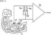
- FIG. 1 is a diagram schematically showing a muscle fatigue evaluation method according to an embodiment of the present invention.
- two electrodes 10 and 20 are disposed at a predetermined interval on a living body surface 30.
- the voltage generated between the electrodes 10 and 20 is measured by being amplified by an amplifier (voltage measurement means) 40.
- a first external resistor Rg1 and a second external resistor Rg2 are disposed in parallel between the two electrodes 10 and 20.
- a switch (connecting means) SW switches between a state in which the first external resistor Rg1 is connected in parallel between the electrodes 10 and 20 and a state in which the second external resistor Rg2 is connected in parallel between the electrodes 10 and 20.
- FIG. 2 shows an equivalent circuit diagram of the state shown in FIG. 1 .
- Vb is the myoelectric potential at the muscle site (brachial muscle) under the living body surface 30 between the two electrodes 10 and 20.
- This myoelectric potential Vb is generated when the upper arm 30 is exercised, that is, when a load is applied to the brachial muscle.
- Rb1 and Rb2 respectively indicate the bioimpedance between a signal source S that generates the myoelectric potential Vb, and the electrodes 10 and 20.
- the bioimpedance will be described in detail in the description of the relation to muscle fatigue given below.
- Rin indicates the input resistance of the amplifier 40.
- the voltage generated between the two electrodes 10 and 20 is amplified by the amplifier 40 and measured as the output voltage Vout.
- the first voltage V 1 generated when the first external resistor Rg1 is connected in parallel between the two electrodes 10 and 20 is given by the formula (2).
- V 1 R g1 R b1 + R b2 + R g1 V b
- the second voltage V 2 generated when the second external resistor Rg2 is connected in parallel between the two electrodes 10 and 20 is given by the formula (3).
- V 2 R g2 R b1 + R b2 + R g2 V b
- the bioimpedance Zb between the two electrodes 10 and 20 at the muscle site (brachial muscle) under the living body surface 30 can be calculated based on the voltage ratio (V 1 /V 2 ) between the first voltage V 1 and the second voltage V 2 .
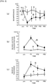
- FIGS. 3(a) to 3(c) are graphs of the results of examining the relation between muscle fatigue and bioimpedance.
- nine healthy adult men were used as subjects, each of whom used a dumbbell with a weight of 60% of the subject's maximum muscle strength to perform 12 arm curls, and this was repeated for five sets to fatigue the brachial muscle.
- FIG. 3(a) is a graph showing the results of measuring the bioimpedance of a subject who performed the above exercise, using the muscle fatigue evaluation method shown in FIGS. 1 and 2 .
- the bioimpedance was measured by attaching two electrodes at an interval of 3.5 cm along the muscle fibers of the brachial muscle in the muscle fatigue evaluation method shown in FIGS. 1 and 2 .
- the resistance value of the first external resistor Rg1 was set so that the voltage ratio V 1 /V 2 between the first voltage V 1 and the second voltage V 2 was about 0.3.
- the resistance value of the second external resistor Rg2 was set to infinity. Then, the first voltage V 1 and the second voltage V 2 were measured while using a 4.0-kg dumbbell and holding the elbow joint angle at 90°.
- the above formula (3) is V 2 ⁇ Vb, so the bioimpedance Zb can be obtained by the following formula (4).
- the horizontal axis indicates time (minutes) and the vertical axis indicates bioimpedance (k ⁇ ).
- Graph A in the drawing shows the bioimpedance measured when the above exercise was not performed, and graph B shows the bioimpedance measured when the above exercise was performed.
- the bioimpedance in the graphs shows the average for nine people.
- the bioimpedance at P0 on the horizontal axis indicates the value immediately after the exercise, and the bioimpedance at P15 to P60 indicates the values measured every 15 minutes after the exercise ended.
- the bioimpedance can be seen to decrease greatly immediately after the above exercise (P0). It can also be seen that the bioimpedance gradually returns as time passes (P15 to P60) after the exercise is finished.
- FIG. 3(b) is a graph showing the results of measuring the blood lactate concentration by taking blood samples from the subjects at P0, P30, and P60.
- Graph A in the drawing shows the blood lactate concentration measured when the above exercise was not performed, and graph B shows the blood lactate concentration measured when the exercise was performed.
- the blood lactate concentration shown in the drawings is the average for nine people.
- FIG. 3(c) is a graph of the results of measuring the muscle thickness in the upper arm of the subject at P0, P30, and P60.
- Graph A in the drawing shows the muscle thickness measured when the above exercise was not performed, and graph B shows the muscle thickness measured when exercise was performed.
- the muscle thickness in the drawings shows the average value for nine people.
- FIG. 4 is a graph schematically showing the relation between the change in the amount of water in a muscle ( FIG. 4(a) ) and the change in the bioimpedance ( FIG. 4(b) ).
- FIGS. 4(a) and 4(b) when a load to is applied to the muscle and muscle fatigue occurs, the amount of water in the muscle increases (time to to ti), and the bioimpedance decreases along with this (time to to ti).
- the load on the muscle is stopped, the amount of water in the muscle returns to its original state (time t 1 to t 2 ), and along with this, the bioimpedance also returns to its original state (time t 1 to t 2 ).
- the bioimpedance may change over time due to factors other than muscle fatigue, even when no exercise is performed. Therefore, when muscle fatigue is evaluated based on the change over time in bioimpedance, it is necessary to distinguish from the change over time due to factors other than muscle fatigue.
- the amount of change over time (slope) L 1 in bioimpedance when exercise is not performed is less than the amount of change over time (slope) L 2 in bioimpedance when exercise is performed.
- the bioimpedance immediately after exercise changes by 20% or more with respect to the bioimpedance before exercise, this is believed to be due to muscle fatigue.
- muscle fatigue can be correctly evaluated by determining that muscle fatigue has occurred when an amount of the change over time in the bioimpedance calculated after exercise is equal to or greater than a predetermined value.
- a certain fluctuation ⁇ occurs in the calculation of the bioimpedance. Accordingly, when muscle fatigue is evaluated based on the change over time in the calculated bioimpedance, it is necessary to distinguish from the change over time due to fluctuation in the bioimpedance. Therefore, the bioimpedance is calculated a number of times before exercise to obtain the fluctuation of the calculated bioimpedance, and muscle fatigue is evaluated based on the change over time when the bioimpedance calculated after exercise is greater than or equal to the fluctuation, which allows muscle fatigue to be correctly evaluated.
- transient muscle fatigue acute muscle fatigue
- muscle fatigue chronic muscle fatigue
- the muscle fatigue evaluation method of this embodiment allows these acute muscle fatigue and chronic muscle fatigue to be evaluated in real time.
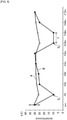
- FIG. 5 is a graph of the results of measuring the bioimpedance of a subject who has exercised, using the muscle fatigue evaluation method shown in FIGS. 1 and 2 .
- the bioimpedance was measured by the same method as that shown in FIG. 3(a) .
- the horizontal axis indicates time and the vertical axis indicates bioimpedance (k ⁇ ).
- Graph A in the drawing shows the bioimpedance measured when exercise was not performed, and graph B shows the bioimpedance measured when exercise was performed.
- the bioimpedance at pre on the horizontal axis indicates the value before exercise, and the bioimpedance at P0 on the horizontal axis indicates the value immediately after exercise is finished.
- P30, P60, P2hr, P3hr, P24hr, P36hr, P48hr, and P72hr on the horizontal axis indicate 30 minutes, 60 minutes, 2 hours, 3 hours, 24 hours, 36 hours, 48 hours, and 72 hours after exercise, respectively.
- the bioimpedance can be seen to have greatly decreased, reaching the minimal value S 1 . After this, it can be seen that the bioimpedance gradually returns as time passes (P30 to P60), reaching the pre-exercise value about 2 hours later (P2hr).
- the bioimpedance again greatly decreases after about 3 hours (P3hr), and can be seen to have reached the second minimal value S 2 after about 24 hours (P24hr).
- the second minimal value S 2 continues for about 12 hours (T), and after 36 hours (P36hr), the bioimpedance can be seen to have gradually returned to the pre-exercise value after about 72 hours (P72hr).
- the muscle fatigue at the point when the initial minimal value S 1 is reached can be determined to be acute muscle fatigue. Also, the muscle fatigue at the point when the next minimal value S 2 is reached after the initial minimal value S 1 can be determined to be chronic muscle fatigue.
- the duration of the minimal value S 1 is the time it takes from the rapid decrease to the rapid increase
- the duration of the minimal value S 2 is the time it takes from the rapid decrease to the rapid increase after a certain amount of time has elapsed. That is, the duration of the minimal value S 2 is longer than the duration of the minimal value S 1 . Therefore, muscle fatigue when the duration of the minimal value S 1 is short can be determined to be acute muscle fatigue, and muscle fatigue when the duration of the minimal value S 2 is long can be determined to be chronic muscle fatigue.
- the muscle fatigue evaluation method in this embodiment comprises disposing at least two electrodes 10 and 20 at a predetermined interval on the living body surface, measuring the first voltage V 1 generated when the first external resistor Rg1 is connected in parallel between the two electrodes 10 and 20 and the second voltage V 2 generated when the second external resistor Rg2 is connected in parallel between the two electrodes 10 and 20, calculating the bioimpedance Zb between the two electrodes 10 and 20 at a muscle site under the living body surface based on the voltage ratio V 1 /V 2 between the first voltage V 1 and the second voltage V 2 , and evaluating the local muscle fatigue at the muscle site based on the change over time in the calculated bioimpedance Zb.
- muscle fatigue that occurs when a non-constant load is applied to a specific muscle to be evaluated in real time. Also, since muscle fatigue at a specific muscle site to be evaluated for fatigue can be evaluated merely by disposing two electrodes at this site, muscle fatigue can be evaluated accurately and non-invasively.
- the present invention provides this effect, muscle fatigue can be evaluated for each specific muscle in daily training, for example, so more effective training can be performed. Also, since muscle fatigue can be evaluated in real time, this prevents the exacerbation of a condition or the occurrence of injuries caused by overtraining.
- the two electrodes 10 and 20 are disposed on the living body surface, but a ground electrode may be disposed on the living body surface and the voltage generated between the two electrodes 10 and 20 may be measured with a differential amplifier 40.
- the bioimpedance between the two electrodes 10 and 20 can be obtained from the above formula (1).
- the first voltage V 1 and the second voltage V 2 are measured by being amplified by the differential amplifier 40 after taking the difference therebetween, external noise can be removed. This allows the bioimpedance Zb to be measured more accurately.
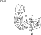
- the two electrodes when evaluating muscle fatigue at a muscle site formed of muscle fibers (brachial muscle), are disposed near each other along the muscle fibers, but as shown in FIG. 6 , they may instead be disposed near each other so as to surround the muscle fibers.
- the muscle fatigue evaluation system can also be used as a muscle fatigue evaluation system. That is, the muscle fatigue evaluation system according to the present invention comprises at least two electrodes disposed at a predetermined interval on the living body surface, a connection means for switchably connecting a first external resistor and a second external resistor in parallel between the two electrodes, a voltage measurement means for measuring the first voltage V 1 generated when the first external resistor is connected in parallel between the two electrodes by the connecting means, and the second voltage V 2 generated when the second external resistor is connected in parallel between the two electrodes by the connecting means, and an impedance calculation means for calculating the bioimpedance between the two electrodes at a muscle site under the living body surface based on the voltage ratio V 1 /V 2 between the first voltage V 1 and the second voltage V 2 .
- the local muscle fatigue at the muscle site is then evaluated based on the change over time in the calculated bioimpedance.
Landscapes
- Health & Medical Sciences (AREA)
- Life Sciences & Earth Sciences (AREA)
- Biomedical Technology (AREA)
- Heart & Thoracic Surgery (AREA)
- Veterinary Medicine (AREA)
- Physics & Mathematics (AREA)
- Public Health (AREA)
- Biophysics (AREA)
- Pathology (AREA)
- Engineering & Computer Science (AREA)
- General Health & Medical Sciences (AREA)
- Animal Behavior & Ethology (AREA)
- Medical Informatics (AREA)
- Molecular Biology (AREA)
- Surgery (AREA)
- Orthopedic Medicine & Surgery (AREA)
- Dentistry (AREA)
- Oral & Maxillofacial Surgery (AREA)
- Rheumatology (AREA)
- Nuclear Medicine, Radiotherapy & Molecular Imaging (AREA)
- Radiology & Medical Imaging (AREA)
- Measurement And Recording Of Electrical Phenomena And Electrical Characteristics Of The Living Body (AREA)
Abstract
Description
- The present invention relates to a muscle fatigue evaluation method and a muscle fatigue evaluation system for evaluating fatigue of a specific muscle by measuring the impedance in a living body.
- As a method for easily evaluating a muscle fatigue state, a method to measure the impedance in a living body by passing a high-frequency current from the outside into the living body is known (see,
Patent Literature 1, for example). - However, this method requires a high-frequency current to flow from the outside into the living body, which poses the risk of an electric shock or the like. In addition, it is difficult to evaluate the fatigue of a specific muscle because the overall impedance in the living body is measured.
- By contrast, a method to measure an electromyogram is known as a method for non-invasively evaluating a muscle fatigue state (see Non-Patent
Literature 1, for example). This method allows the fatigue of a specific muscle to be evaluated by measuring changes in the amplitude and the center frequency of the electromyogram. - [Patent Literature 1]
Japanese Patent Application Publication No. 2004-49789 - [Non-Patent Literature 1] Tomohiro Kizuka, Tadashi Masuda, Tohru Kiryu, and Tsugutake Sadoyama, "Practical Usage of Surface Electromyogram," Tokyo Denki University Press, March 2006, pp. 60-62.
- However, since an electromyogram is a record of biological signals obtained by causing a muscle to contract, the amplitude and the center frequency change when the magnitude of the load applied to the muscle is changed. Therefore, muscle fatigue can be evaluated only when a load of a certain magnitude has been applied to the muscle. That is, an electromyogram, by itself, is not an index for evaluating muscle fatigue that occurs continuously in a state in which a non-constant load is applied to the muscle.
- The present invention is conceived in the light of this point, and a main object thereof is to provide a non-invasive muscle fatigue evaluation method and muscle fatigue evaluation system with which the muscle fatigue that occurs when a non-constant load is applied to a specific muscle can be evaluated.
- A muscle fatigue evaluation method according to the present invention comprises disposing at least two electrodes at a predetermined interval on a living body surface, measuring a first voltage V1 generated when a first external resistor is connected in parallel between the two electrodes and a second voltage V2 generated when a second external resistor is connected in parallel between the two electrodes, calculating a bioimpedance between the two electrodes at a muscle site under the living body surface based on a voltage ratio V1/V2 between the first voltage V1 and the second voltage V2, and evaluating local muscle fatigue at the muscle site based on a change overtime in the calculated bioimpedance.
- A muscle fatigue evaluation system according to the present invention comprises at least two electrodes disposed at a predetermined interval on a living body surface, a connection means for switchably connecting a first external resistor and a second external resistor in parallel between the two electrodes, a voltage measurement means for measuring a first voltage V1 generated when the first external resistor is connected in parallel between the two electrodes by the connecting means, and a second voltage V2 generated when the second external resistor is connected in parallel between the two electrodes by the connecting means, and an impedance calculation means for calculating a bioimpedance between the two electrodes at a muscle site under the living body surface based on a voltage ratio V1/V2 between the first voltage V1 and the second voltage V2, local muscle fatigue at the muscle site being evaluated based on a change over time in the calculated bioimpedance.
- The present invention allows muscle fatigue that occurs when a non-constant load is applied to a specific muscle to be continuously and non-invasively evaluated.
-
-
FIG. 1 is a diagram schematically showing a muscle fatigue evaluation method according to an embodiment of the present invention; -
FIG. 2 is an equivalent circuit diagram in the state shown inFIG. 1 ; -
FIGS. 3(a) to 3(c) are graphs of the results of examining the relation between muscle fatigue and bioimpedance; -
FIGS. 4(a) and 4(b) are graphs schematically showing the relation between the change in the amount of water in a muscle and the change in bioimpedance; -
FIG. 5 is a graph of the results of examining acute muscle fatigue and chronic muscle fatigue; and -
FIG. 6 is a diagram showing an arrangement of the two electrodes. - Embodiments of the present invention will now be described in detail with reference to the drawings. The present invention is not limited to the following embodiments. Also, suitable changes are possible to the extent that such changes do not deviate from the range in which the effect of the present invention is exhibited.
-
FIG. 1 is a diagram schematically showing a muscle fatigue evaluation method according to an embodiment of the present invention. - As shown in
FIG. 1 , twoelectrodes living body surface 30. Here, an example is given in which the twoelectrodes electrodes electrodes electrodes electrodes -
FIG. 2 shows an equivalent circuit diagram of the state shown inFIG. 1 . - Here, Vb is the myoelectric potential at the muscle site (brachial muscle) under the
living body surface 30 between the twoelectrodes upper arm 30 is exercised, that is, when a load is applied to the brachial muscle. - Also, Rb1 and Rb2 respectively indicate the bioimpedance between a signal source S that generates the myoelectric potential Vb, and the
electrodes amplifier 40. The voltage generated between the twoelectrodes amplifier 40 and measured as the output voltage Vout. - In the equivalent circuit diagram shown in
FIG. 2 , the first voltage V1 generated when the first external resistor Rg1 is connected in parallel between the twoelectrodes -

- The second voltage V2 generated when the second external resistor Rg2 is connected in parallel between the two
electrodes -

- Therefore, using the formulas (2) and (3), the bioimpedance Zb (= Rb1 + Rb2) between the two
electrodes living body surface 30 is obtained by the following formula (1). -

- That is, using the formula (1), the bioimpedance Zb between the two
electrodes living body surface 30 can be calculated based on the voltage ratio (V1/V2) between the first voltage V1 and the second voltage V2. - On the other hand, it is well known that the blood lactate concentration increases when a load is applied to muscles to the point that muscle fatigue occurs, but it is also known that the water content in muscles also increases. Therefore, when the bioimpedance at the fatigued muscle site is measured, it can be predicted that the bioimpedance will be lower than normal.
-
FIGS. 3(a) to 3(c) are graphs of the results of examining the relation between muscle fatigue and bioimpedance. In the test, nine healthy adult men were used as subjects, each of whom used a dumbbell with a weight of 60% of the subject's maximum muscle strength to perform 12 arm curls, and this was repeated for five sets to fatigue the brachial muscle. -
FIG. 3(a) is a graph showing the results of measuring the bioimpedance of a subject who performed the above exercise, using the muscle fatigue evaluation method shown inFIGS. 1 and2 . The bioimpedance was measured by attaching two electrodes at an interval of 3.5 cm along the muscle fibers of the brachial muscle in the muscle fatigue evaluation method shown inFIGS. 1 and2 . - Here, the resistance value of the first external resistor Rg1 was set so that the voltage ratio V1/V2 between the first voltage V1 and the second voltage V2 was about 0.3. The resistance value of the second external resistor Rg2 was set to infinity. Then, the first voltage V1 and the second voltage V2 were measured while using a 4.0-kg dumbbell and holding the elbow joint angle at 90°.
- When the resistance value of the second external resistance Rg2 is set to infinity, the above formula (3) is V2 ≈ Vb, so the bioimpedance Zb can be obtained by the following formula (4).
-

- In
FIG. 3(a) , the horizontal axis indicates time (minutes) and the vertical axis indicates bioimpedance (kΩ). Graph A in the drawing shows the bioimpedance measured when the above exercise was not performed, and graph B shows the bioimpedance measured when the above exercise was performed. The bioimpedance in the graphs shows the average for nine people. - The bioimpedance at P0 on the horizontal axis indicates the value immediately after the exercise, and the bioimpedance at P15 to P60 indicates the values measured every 15 minutes after the exercise ended.
- As shown in
FIG. 3(a) , the bioimpedance can be seen to decrease greatly immediately after the above exercise (P0). It can also be seen that the bioimpedance gradually returns as time passes (P15 to P60) after the exercise is finished. -
FIG. 3(b) is a graph showing the results of measuring the blood lactate concentration by taking blood samples from the subjects at P0, P30, and P60. Graph A in the drawing shows the blood lactate concentration measured when the above exercise was not performed, and graph B shows the blood lactate concentration measured when the exercise was performed. The blood lactate concentration shown in the drawings is the average for nine people. - As shown in
FIG. 3(b) , it can be seen that the blood lactate concentration is greatly increased immediately after the above exercise (P0). It can also be seen that the blood lactate concentration gradually returns as time passes (P30, P60) after the exercise is finished. -
FIG. 3(c) is a graph of the results of measuring the muscle thickness in the upper arm of the subject at P0, P30, and P60. Graph A in the drawing shows the muscle thickness measured when the above exercise was not performed, and graph B shows the muscle thickness measured when exercise was performed. The muscle thickness in the drawings shows the average value for nine people. - As shown in
FIG. 3(c) , it can be seen that the muscle thickness is greatly increased immediately after the above exercise (P0). It can also be seen that the muscle thickness gradually returns as time passes (P30, P60) after the exercise is finished. - It can be seen from the above results that the change in bioimpedance when a non-constant load is applied to the muscle, such as in biceps curls, is strongly correlated with the change in blood lactate concentration and the change in muscle thickness. That is, the fatigue of a specific muscle can be ascertained as the change in the amount of water in the muscle, and this tells us that the change in bioimpedance can serve as an index reflecting muscle fatigue.
- As explained above, when a load to is applied to a muscle and muscle fatigue occurs, the amount of water in the muscle changes, and the fatigue in a specific muscle can be evaluated in real time by ascertaining the change in the amount of water in the muscle as the change in bioimpedance.
-
FIG. 4 is a graph schematically showing the relation between the change in the amount of water in a muscle (FIG. 4(a) ) and the change in the bioimpedance (FIG. 4(b) ). As shown inFIGS. 4(a) and 4(b) , when a load to is applied to the muscle and muscle fatigue occurs, the amount of water in the muscle increases (time to to ti), and the bioimpedance decreases along with this (time to to ti). When the load on the muscle is stopped, the amount of water in the muscle returns to its original state (time t1 to t2), and along with this, the bioimpedance also returns to its original state (time t1 to t2). That is, measuring the change over time in the bioimpedance reveals that muscle fatigue accumulates from the time to to t1, and is restored between the times t1 and t2. Consequently, it possible to evaluate in real time the muscle fatigue that occurs when a load is applied to muscles. - As shown in graph A in
FIG. 3(a) , the bioimpedance may change over time due to factors other than muscle fatigue, even when no exercise is performed. Therefore, when muscle fatigue is evaluated based on the change over time in bioimpedance, it is necessary to distinguish from the change over time due to factors other than muscle fatigue. - Usually, as shown in
FIG. 3(a) , the amount of change over time (slope) L1 in bioimpedance when exercise is not performed is less than the amount of change over time (slope) L2 in bioimpedance when exercise is performed. Typically, when the bioimpedance immediately after exercise changes by 20% or more with respect to the bioimpedance before exercise, this is believed to be due to muscle fatigue. - On the other hand, when the change over time in the bioimpedance is 20% or less, this is not believed to be due to muscle fatigue. Therefore, muscle fatigue can be correctly evaluated by determining that muscle fatigue has occurred when an amount of the change over time in the bioimpedance calculated after exercise is equal to or greater than a predetermined value.
- Also, as shown in
FIG. 3(a) , a certain fluctuation Δ occurs in the calculation of the bioimpedance. Accordingly, when muscle fatigue is evaluated based on the change over time in the calculated bioimpedance, it is necessary to distinguish from the change over time due to fluctuation in the bioimpedance. Therefore, the bioimpedance is calculated a number of times before exercise to obtain the fluctuation of the calculated bioimpedance, and muscle fatigue is evaluated based on the change over time when the bioimpedance calculated after exercise is greater than or equal to the fluctuation, which allows muscle fatigue to be correctly evaluated. - On the other hand, it is known that when a load is applied to a muscle, transient muscle fatigue (acute muscle fatigue) initially occurs, after which the muscle fatigue recovers, and then muscle fatigue (chronic muscle fatigue) occurs again.
- The muscle fatigue evaluation method of this embodiment allows these acute muscle fatigue and chronic muscle fatigue to be evaluated in real time.
-
FIG. 5 is a graph of the results of measuring the bioimpedance of a subject who has exercised, using the muscle fatigue evaluation method shown inFIGS. 1 and2 . The bioimpedance was measured by the same method as that shown inFIG. 3(a) . - In
FIG. 5 , the horizontal axis indicates time and the vertical axis indicates bioimpedance (kΩ). Graph A in the drawing shows the bioimpedance measured when exercise was not performed, and graph B shows the bioimpedance measured when exercise was performed. - The bioimpedance at pre on the horizontal axis indicates the value before exercise, and the bioimpedance at P0 on the horizontal axis indicates the value immediately after exercise is finished. P30, P60, P2hr, P3hr, P24hr, P36hr, P48hr, and P72hr on the horizontal axis indicate 30 minutes, 60 minutes, 2 hours, 3 hours, 24 hours, 36 hours, 48 hours, and 72 hours after exercise, respectively.
- As shown in
FIG. 5 , immediately after exercise is finished (P0), the bioimpedance can be seen to have greatly decreased, reaching the minimal value S1. After this, it can be seen that the bioimpedance gradually returns as time passes (P30 to P60), reaching the pre-exercise value about 2 hours later (P2hr). - As more time passes, the bioimpedance again greatly decreases after about 3 hours (P3hr), and can be seen to have reached the second minimal value S2 after about 24 hours (P24hr). The second minimal value S2 continues for about 12 hours (T), and after 36 hours (P36hr), the bioimpedance can be seen to have gradually returned to the pre-exercise value after about 72 hours (P72hr).
- In the change over time in the bioimpedance shown in
FIG. 5 , the muscle fatigue at the point when the initial minimal value S1 is reached can be determined to be acute muscle fatigue. Also, the muscle fatigue at the point when the next minimal value S2 is reached after the initial minimal value S1 can be determined to be chronic muscle fatigue. - Also, in the change over time in the bioimpedance shown in
FIG. 5 , the duration of the minimal value S1 is the time it takes from the rapid decrease to the rapid increase, whereas the duration of the minimal value S2 is the time it takes from the rapid decrease to the rapid increase after a certain amount of time has elapsed. That is, the duration of the minimal value S2 is longer than the duration of the minimal value S1. Therefore, muscle fatigue when the duration of the minimal value S1 is short can be determined to be acute muscle fatigue, and muscle fatigue when the duration of the minimal value S2 is long can be determined to be chronic muscle fatigue. - Thus, with the muscle fatigue evaluation method in this embodiment, acute muscle fatigue and chronic muscle fatigue that occur after applying a load to a muscle can be evaluated in real time and non-invasively. In particular, evaluating chronic muscle fatigue used to demand a high degree of specialized knowledge, but in this embodiment, chronic muscle fatigue can be evaluated by a simple method. As a result, it is possible to prevent the risk of injury or the like posed by training in a state in which chronic muscle fatigue remains, and to prevent a decrease in the training effect, as well as the occurrence of overtraining due to excessive training.
- The muscle fatigue evaluation method in this embodiment comprises disposing at least two
electrodes electrodes electrodes electrodes - This allows muscle fatigue that occurs when a non-constant load is applied to a specific muscle to be evaluated in real time. Also, since muscle fatigue at a specific muscle site to be evaluated for fatigue can be evaluated merely by disposing two electrodes at this site, muscle fatigue can be evaluated accurately and non-invasively.
- Because the present invention provides this effect, muscle fatigue can be evaluated for each specific muscle in daily training, for example, so more effective training can be performed. Also, since muscle fatigue can be evaluated in real time, this prevents the exacerbation of a condition or the occurrence of injuries caused by overtraining.
- The present invention was described above in terms of a preferred embodiment, but this description is not a limitation, and various modifications are, of course, possible.
- For example, in the above embodiment, the two
electrodes electrodes differential amplifier 40. Here again, the bioimpedance between the twoelectrodes differential amplifier 40 after taking the difference therebetween, external noise can be removed. This allows the bioimpedance Zb to be measured more accurately. - Also, in the above embodiment, when evaluating muscle fatigue at a muscle site formed of muscle fibers (brachial muscle), the two electrodes are disposed near each other along the muscle fibers, but as shown in
FIG. 6 , they may instead be disposed near each other so as to surround the muscle fibers. - The present invention can also be used as a muscle fatigue evaluation system. That is, the muscle fatigue evaluation system according to the present invention comprises at least two electrodes disposed at a predetermined interval on the living body surface, a connection means for switchably connecting a first external resistor and a second external resistor in parallel between the two electrodes, a voltage measurement means for measuring the first voltage V1 generated when the first external resistor is connected in parallel between the two electrodes by the connecting means, and the second voltage V2 generated when the second external resistor is connected in parallel between the two electrodes by the connecting means, and an impedance calculation means for calculating the bioimpedance between the two electrodes at a muscle site under the living body surface based on the voltage ratio V1/V2 between the first voltage V1 and the second voltage V2. The local muscle fatigue at the muscle site is then evaluated based on the change over time in the calculated bioimpedance.
-
- 10
- electrode
- 20
- electrode
- 30
- living body surface
- 40
- amplifier (differential amplifier)
- Rg1
- first external resistor
- Rg2
- second external resistor
Claims (10)
- A muscle fatigue evaluation method comprising:disposing at least two electrodes at a predetermined interval on a living body surface;measuring a first voltage V1 generated when a first external resistor is connected in parallel between the two electrodes and a second voltage V2 generated when a second external resistor is connected in parallel between the two electrodes;calculating a bioimpedance between the two electrodes at a muscle site under the living body surface based on a voltage ratio V1/V2 between the first voltage V1 and the second voltage V2; andevaluating local muscle fatigue at the muscle site based on a change over time in the calculated bioimpedance.
- The muscle fatigue evaluation method according to claim 1, wherein
the bioimpedance Zb is measured based on the following formula (1):
[First Mathematical Formula]
- The muscle fatigue evaluation method according to claim 1 or 2, wherein
one of the first external resistance and the second external resistance has infinite resistance. - The muscle fatigue evaluation method according to any one of claims 1 to 3, wherein
the two electrodes are disposed near each other on the living body surface at a muscle site formed of muscle fibers along the muscle fibers. - The muscle fatigue evaluation method according to any one of claims 1 to 3, wherein
the two electrodes are disposed near each other on the living body surface at a muscle site formed of muscle fibers so as to surround the muscle fibers. - The muscle fatigue evaluation method according to claim 1, whereinthe bioimpedance between the two electrodes is calculated after exercise, andthe muscle fatigue is determined to have occurred when an amount of the change over time in the bioimpedance calculated after exercise is equal to or greater than a predetermined value.
- The muscle fatigue evaluation method according to claim 1, whereinthe bioimpedance between the two electrodes is calculated before exercise to obtain fluctuation in the calculated bioimpedance, andthe muscle fatigue is evaluated based on the change over time when the bioimpedance calculated after exercise is equal to or greater than the fluctuation.
- The muscle fatigue evaluation method according to claim 6 or 7, wherein
the muscle fatigue at a point when an initial minimal value is reached in the change over time in the calculated bioimpedance is determined to be acute muscle fatigue, and the muscle fatigue at a point when the next minimal value is reached from the minimal value is determined to be chronic muscle fatigue. - The muscle fatigue evaluation method according to claim 6 or 7, wherein
the muscle fatigue at a point when a duration of a minimal value in the change over time in the calculated bioimpedance is short is determined to be acute muscle fatigue, and the muscle fatigue at a point when the duration of the minimal value is long is determined to be chronic muscle fatigue. - A muscle fatigue evaluation system comprising:at least two electrodes disposed at a predetermined interval on a living body surface;a connection means for switchably connecting a first external resistor and a second external resistor in parallel between the two electrodes;a voltage measurement means for measuring a first voltage V1 generated when the first external resistor is connected in parallel between the two electrodes by the connecting means, and a second voltage V2 generated when the second external resistor is connected in parallel between the two electrodes by the connecting means; andan impedance calculation means for calculating a bioimpedance between the two electrodes at a muscle site under the living body surface based on a voltage ratio V1/V2 between the first voltage V1 and the second voltage V2,local muscle fatigue at the muscle site being evaluated based on a change over time in the calculated bioimpedance.
Applications Claiming Priority (3)
| Application Number | Priority Date | Filing Date | Title |
|---|---|---|---|
| JP2019051809 | 2019-03-19 | ||
| JP2019151181A JP2020157037A (en) | 2019-03-19 | 2019-08-21 | Muscle fatigue evaluation method and muscle fatigue evaluation system |
| PCT/JP2020/010076 WO2020189384A1 (en) | 2019-03-19 | 2020-03-09 | Muscle fatigue evaluation method and muscle fatigue evaluation system |
Publications (2)
| Publication Number | Publication Date |
|---|---|
| EP3943003A1 true EP3943003A1 (en) | 2022-01-26 |
| EP3943003A4 EP3943003A4 (en) | 2022-06-22 |
Family
ID=72520326
Family Applications (1)
| Application Number | Title | Priority Date | Filing Date |
|---|---|---|---|
| EP20772707.4A Withdrawn EP3943003A4 (en) | 2019-03-19 | 2020-03-09 | Muscle fatigue evaluation method and muscle fatigue evaluation system |
Country Status (3)
| Country | Link |
|---|---|
| US (1) | US20210393192A1 (en) |
| EP (1) | EP3943003A4 (en) |
| WO (1) | WO2020189384A1 (en) |
Families Citing this family (2)
| Publication number | Priority date | Publication date | Assignee | Title |
|---|---|---|---|---|
| US20240207682A1 (en) * | 2022-12-23 | 2024-06-27 | Meta Platforms Technologies, Llc | Detecting Neuromuscular Signals at a Wearable Device to Facilitate Performance of Physical Activities, and Methods and Systems Thereof |
| JP2024101441A (en) * | 2023-01-17 | 2024-07-29 | 株式会社豊田中央研究所 | Muscle fatigue measuring device, muscle fatigue measuring method, and muscle fatigue measuring program |
Family Cites Families (9)
| Publication number | Priority date | Publication date | Assignee | Title |
|---|---|---|---|---|
| US5415176A (en) * | 1991-11-29 | 1995-05-16 | Tanita Corporation | Apparatus for measuring body fat |
| DE20116409U1 (en) * | 2000-09-30 | 2002-01-24 | Fook Tin Plastic Factory Ltd., Quarry Bay | Body fat measuring device |
| JP2004049789A (en) | 2002-07-24 | 2004-02-19 | Tanita Corp | Muscle fatigue measurement device |
| JP3948617B2 (en) * | 2002-10-22 | 2007-07-25 | 株式会社タニタ | Muscle measuring device |
| JP3960475B2 (en) * | 2002-12-25 | 2007-08-15 | 株式会社タニタ | Muscle fatigue measurement device |
| JP2005296415A (en) * | 2004-04-13 | 2005-10-27 | Tanita Corp | Body composition measuring device |
| JP2012200490A (en) * | 2011-03-28 | 2012-10-22 | Toyota Central R&D Labs Inc | Muscle fatigue reducing device |
| JP6492103B2 (en) * | 2014-11-14 | 2019-03-27 | 東レエンジニアリング株式会社 | In vivo signal source position detection method and in vivo signal source position detection apparatus |
| JP6770266B2 (en) * | 2016-08-18 | 2020-10-14 | 東レエンジニアリング株式会社 | In-vivo signal source detection method and in-vivo signal source detection device |
-
2020
- 2020-03-09 EP EP20772707.4A patent/EP3943003A4/en not_active Withdrawn
- 2020-03-09 WO PCT/JP2020/010076 patent/WO2020189384A1/en not_active Ceased
-
2021
- 2021-08-31 US US17/462,468 patent/US20210393192A1/en not_active Abandoned
Also Published As
| Publication number | Publication date |
|---|---|
| WO2020189384A1 (en) | 2020-09-24 |
| EP3943003A4 (en) | 2022-06-22 |
| US20210393192A1 (en) | 2021-12-23 |
Similar Documents
| Publication | Publication Date | Title |
|---|---|---|
| Rainoldi et al. | Repeatability of surface EMG variables during voluntary isometric contractions of the biceps brachii muscle | |
| Thongpanja et al. | Mean and median frequency of EMG signal to determine muscle force based on time-dependent power spectrum | |
| Stamford | Validity and reliability of subjective ratings of perceived exertion during work | |
| Dolan et al. | Fatigue of the erector spinae muscles: a quantitative assessment using “frequency banding” of the surface electromyography signal | |
| US6266558B1 (en) | Apparatus and method for nerve conduction measurements with automatic setting of stimulus intensity | |
| Clancy et al. | Relating agonist-antagonist electromyograms to joint torque during isometric, quasi-isotonic, nonfatiguing contractions | |
| Woodward et al. | Segmenting mechanomyography measures of muscle activity phases using inertial data | |
| US9402579B2 (en) | Real-time assessment of absolute muscle effort during open and closed chain activities | |
| Dankel et al. | The impact of acute and chronic resistance exercise on muscle stiffness: a systematic review and meta-analysis | |
| Bartuzi et al. | Assessment of muscle load and fatigue with the usage of frequency and time-frequency analysis of the EMG signal | |
| Rodríguez-Rosell et al. | Role of the effort index in predicting neuromuscular fatigue during resistance exercises | |
| EP3943003A1 (en) | Muscle fatigue evaluation method and muscle fatigue evaluation system | |
| Affanni et al. | Wearable instrument for skin potential response analysis in AAL applications | |
| Dvir | How much is necessary to indicate a real improvement in muscle function? A review of modern methods of reproducibility analysis | |
| EP3202319B1 (en) | Method for detecting position of signal source in living body, and device for detecting position of signal source in living body | |
| Thongpanja et al. | A feasibility study of fatigue and muscle contraction indices based on EMG time-dependent spectral analysis | |
| Matthijsse et al. | Ankle angle effects on endurance time, median frequency and mean power of gastrocnemius EMG power spectrum: a comparison between individual and group analysis | |
| RU2166280C2 (en) | Method for evaluating vegetative nervous system state | |
| JP2020157037A (en) | Muscle fatigue evaluation method and muscle fatigue evaluation system | |
| Jung et al. | Estimating fatigue level of femoral and gastrocemius muscles based on surface electromyography in time and frequency domain | |
| Doulah et al. | An approach to identify myopathy disease using different signal processing features with comparison | |
| Bohannon | Internal consistency of dynamometer measurements in healthy subjects and stroke patients | |
| RU2269927C2 (en) | Method for increasing objectivity level of manual muscle testing | |
| Kuenze et al. | Validity of torque-data collection at multiple sites: a framework for collaboration on clinical-outcomes research in sports medicine | |
| Della Santa et al. | Comfort assessment in the use of shotgun for skeet shooting: an EMG based approach |
Legal Events
| Date | Code | Title | Description |
|---|---|---|---|
| STAA | Information on the status of an ep patent application or granted ep patent |
Free format text: STATUS: THE INTERNATIONAL PUBLICATION HAS BEEN MADE |
|
| PUAI | Public reference made under article 153(3) epc to a published international application that has entered the european phase |
Free format text: ORIGINAL CODE: 0009012 |
|
| STAA | Information on the status of an ep patent application or granted ep patent |
Free format text: STATUS: REQUEST FOR EXAMINATION WAS MADE |
|
| 17P | Request for examination filed |
Effective date: 20211012 |
|
| AK | Designated contracting states |
Kind code of ref document: A1 Designated state(s): AL AT BE BG CH CY CZ DE DK EE ES FI FR GB GR HR HU IE IS IT LI LT LU LV MC MK MT NL NO PL PT RO RS SE SI SK SM TR |
|
| A4 | Supplementary search report drawn up and despatched |
Effective date: 20220523 |
|
| DAV | Request for validation of the european patent (deleted) | ||
| DAX | Request for extension of the european patent (deleted) | ||
| RIC1 | Information provided on ipc code assigned before grant |
Ipc: A61B 5/389 20210101ALI20220517BHEP Ipc: A61B 5/05 20210101AFI20220517BHEP |
|
| STAA | Information on the status of an ep patent application or granted ep patent |
Free format text: STATUS: THE APPLICATION HAS BEEN WITHDRAWN |
|
| 18W | Application withdrawn |
Effective date: 20240115 |