EP3942960A1 - Shoe - Google Patents
Shoe Download PDFInfo
- Publication number
- EP3942960A1 EP3942960A1 EP19923390.9A EP19923390A EP3942960A1 EP 3942960 A1 EP3942960 A1 EP 3942960A1 EP 19923390 A EP19923390 A EP 19923390A EP 3942960 A1 EP3942960 A1 EP 3942960A1
- Authority
- EP
- European Patent Office
- Prior art keywords
- foot
- tightening force
- width direction
- side portion
- arch
- Prior art date
- Legal status (The legal status is an assumption and is not a legal conclusion. Google has not performed a legal analysis and makes no representation as to the accuracy of the status listed.)
- Pending
Links
- 238000003780 insertion Methods 0.000 claims description 167
- 230000037431 insertion Effects 0.000 claims description 167
- 239000000470 constituent Substances 0.000 claims description 45
- 230000004308 accommodation Effects 0.000 claims description 18
- 230000000452 restraining effect Effects 0.000 claims description 14
- 210000002683 foot Anatomy 0.000 description 143
- 238000012986 modification Methods 0.000 description 17
- 230000004048 modification Effects 0.000 description 17
- 239000000463 material Substances 0.000 description 13
- 210000000452 mid-foot Anatomy 0.000 description 11
- 230000000694 effects Effects 0.000 description 9
- 238000009958 sewing Methods 0.000 description 9
- 238000010586 diagram Methods 0.000 description 6
- 210000000474 heel Anatomy 0.000 description 6
- 239000002649 leather substitute Substances 0.000 description 4
- 210000000459 calcaneus Anatomy 0.000 description 3
- 238000013461 design Methods 0.000 description 3
- 210000003371 toe Anatomy 0.000 description 3
- RTZKZFJDLAIYFH-UHFFFAOYSA-N Diethyl ether Chemical compound CCOCC RTZKZFJDLAIYFH-UHFFFAOYSA-N 0.000 description 2
- 210000000458 cuboid bone Anatomy 0.000 description 2
- 230000005489 elastic deformation Effects 0.000 description 2
- 239000004744 fabric Substances 0.000 description 2
- 230000012447 hatching Effects 0.000 description 2
- 210000000450 navicular bone Anatomy 0.000 description 2
- 230000002093 peripheral effect Effects 0.000 description 2
- 210000004233 talus Anatomy 0.000 description 2
- 210000003423 ankle Anatomy 0.000 description 1
- 210000000988 bone and bone Anatomy 0.000 description 1
- 210000000460 cuneiform bone Anatomy 0.000 description 1
- 230000003247 decreasing effect Effects 0.000 description 1
- 238000012217 deletion Methods 0.000 description 1
- 230000037430 deletion Effects 0.000 description 1
- 230000002349 favourable effect Effects 0.000 description 1
- 210000003871 fifth metatarsal bone Anatomy 0.000 description 1
- 210000000454 fifth toe Anatomy 0.000 description 1
- 210000001906 first metatarsal bone Anatomy 0.000 description 1
- 210000001255 hallux Anatomy 0.000 description 1
- 239000010985 leather Substances 0.000 description 1
- 210000000113 medial cuneiform Anatomy 0.000 description 1
- 210000001872 metatarsal bone Anatomy 0.000 description 1
- 238000000034 method Methods 0.000 description 1
- 229920000728 polyester Polymers 0.000 description 1
- 230000002787 reinforcement Effects 0.000 description 1
- 230000003252 repetitive effect Effects 0.000 description 1
Images










Classifications
-
- A—HUMAN NECESSITIES
- A43—FOOTWEAR
- A43B—CHARACTERISTIC FEATURES OF FOOTWEAR; PARTS OF FOOTWEAR
- A43B23/00—Uppers; Boot legs; Stiffeners; Other single parts of footwear
- A43B23/02—Uppers; Boot legs
- A43B23/0245—Uppers; Boot legs characterised by the constructive form
-
- A—HUMAN NECESSITIES
- A43—FOOTWEAR
- A43B—CHARACTERISTIC FEATURES OF FOOTWEAR; PARTS OF FOOTWEAR
- A43B23/00—Uppers; Boot legs; Stiffeners; Other single parts of footwear
- A43B23/02—Uppers; Boot legs
- A43B23/0245—Uppers; Boot legs characterised by the constructive form
- A43B23/0265—Uppers; Boot legs characterised by the constructive form having different properties in different directions
-
- A—HUMAN NECESSITIES
- A43—FOOTWEAR
- A43B—CHARACTERISTIC FEATURES OF FOOTWEAR; PARTS OF FOOTWEAR
- A43B7/00—Footwear with health or hygienic arrangements
- A43B7/14—Footwear with health or hygienic arrangements with foot-supporting parts
- A43B7/1495—Footwear with health or hygienic arrangements with foot-supporting parts with arch-supports of the bracelet type
-
- A—HUMAN NECESSITIES
- A43—FOOTWEAR
- A43B—CHARACTERISTIC FEATURES OF FOOTWEAR; PARTS OF FOOTWEAR
- A43B7/00—Footwear with health or hygienic arrangements
- A43B7/14—Footwear with health or hygienic arrangements with foot-supporting parts
- A43B7/24—Insertions or other supports preventing the foot canting to one side , preventing supination or pronation
-
- A—HUMAN NECESSITIES
- A43—FOOTWEAR
- A43C—FASTENINGS OR ATTACHMENTS OF FOOTWEAR; LACES IN GENERAL
- A43C1/00—Shoe lacing fastenings
- A43C1/04—Shoe lacing fastenings with rings or loops
Definitions
- the present invention relates to a shoe.
- Patent Literature 1 describes a shoe in which a reinforcement member is disposed within the upper so as to prevent decrement of longitudinal arch heigh.
- Patent Literature 1 Japanese Unexamined Patent Application Publication No. 2016-36703
- the inventors have conducted study and gained the following new recognition.
- the arch support part is integrally formed with the upper, so that the tightening force to be applied to the arch support part may be dispersed and transmitted to the upper. This may cause large resistance in part of the upper other than the arch support part, so that the tightening force may not be sufficiently transmitted to the arch support part, which may therefore be unable to firmly support the longitudinal arch.
- a shoe devised to restrain the lowering of a longitudinal arch has not been proposed.
- One aspect of the present invention has been made in view of such an issue, and a purpose thereof is to provide a shoe which can prevent decrement of longitudinal arch heigh of a foot.
- the shoe includes: an upper; a tightening tool disposed above an instep of a wearer and capable of applying, to the upper, tightening force for drawing portions on the both sides in a foot width direction of the upper; and an arch support part provided such that tightening force applied to a first side portion in a foot width direction of the upper can be transmitted to the arch support part.
- the arch support part is also provided to be capable of supporting, from the underneath, a longitudinal arch on a first side in the foot width direction of a foot of a wearer.
- the first side portion includes a tightening force transmitter provided on the first side in the foot width direction with respect to the arch support part and also provided such that the tightening force applied to the first side portion can be transmitted to the tightening force transmitter.
- the tightening force transmitter has stretchability in foot girth directions set higher than that of the arch support part.
- the shoe includes: an upper; a tightening tool disposed above an instep of a wearer and capable of applying, to the upper, tightening force for drawing portions on the both sides in a foot width direction of the upper; and an arch support part provided such that tightening force applied to a first side portion in a foot width direction of the upper can be transmitted to the arch support part.
- the arch support part is also provided to be capable of supporting, from the underneath, a longitudinal arch on a first side in the foot width direction of a foot of a wearer.
- the first side portion includes a tightening force transmitter provided on the first side in the foot width direction with respect to the arch support part and also provided such that the tightening force applied to the first side portion can be transmitted to the tightening force transmitter.
- the tightening force transmitter is configured such that, when the tightening tool is being tightened, the tightening force is transmitted to the arch support part before the tightening force transmitter.
- FIG. 1 is a plan view in which a skeleton model of a foot is superimposed upon an inner bottom surface 18a of an accommodation room 18 within an upper 14.
- a direction along a long side of the virtual rectangle 16 is defined as a "longitudinal direction X", and a direction along a short side thereof is defined as a "foot width direction Y".
- a "longitudinal direction X" the front side is defined as the toe side of the foot, and the rear side is defined as the heel side of the foot.
- a "foot width direction Y” the medial side is defined as the first toe side of the foot, and the lateral side is defined as the fifth toe side of the foot.
- a direction of circling around the axis of the longitudinal direction X is defined as a "foot girth direction”.
- a line extending along a longitudinal direction X and passing through a position that bisects the aforementioned short side length La of the virtual rectangle 16 will be referred to as a "center line CL1" of the shoe 10.
- a human foot is mainly constituted by cuneiform bones Ba, a cuboid bone Bb, a navicular bone Bc, a talus Bd, a calcaneus Be, metatarsal bones Bf, and phalanges Bg.
- Joints of a foot include MP joints Ja, Lisfranc joints Jb, and a Chopart's joint Jc.
- a “midfoot portion of a foot” means a portion from the MP joints Ja to the Chopart's joint Jc.
- a "longitudinal arch” of a foot means either a “medial longitudinal arch” or a “lateral longitudinal arch”.
- the "medial longitudinal arch” means a region within a range from the calcaneus Be through the talus Bd, the navicular bone Bc, and the medial cuneiform bone Ba to the thenar eminence of the first metatarsal bone Bf on the medial side of a foot.
- the "lateral longitudinal arch” means a region within a range from the calcaneus Be through the cuboid bone Bb to the hypothenar eminence of the fifth metatarsal bone Bf on the lateral side of a foot.
- the "midfoot portion" in terms of a constituting element of a shoe means a region assumed to be overlapped by the midfoot portion of a foot in plan view.
- a line P represents a straight line extending along a foot width direction Y and positioned within a range S1 from 50% to 75% of the entire length Lb of the shoe 10 from the heel side.
- a line Q represents a straight line extending along a foot width direction Y and positioned within a range S2 from 20% to 45% of the entire length Lb of the shoe 10 from the heel side.
- the "midfoot portion" in terms of a constituting element of a shoe means a region between the line P and the line Q in plan view.
- the medial side is defined as a first side of the both foot width directions
- the lateral side is defined as a second side thereof.
- a supination direction is defined as a first side of the both foot girth directions
- a pronation direction is defined as a second side thereof.
- Each embodiment describes a shoe with which excessive pronation in the pronation direction can be prevented.
- FIGS. 2-4 are now referred to.
- the shoe 10 according to the first embodiment will be described. Although a shoe for a right foot is illustrated, the following description is also applicable to a shoe for a left foot.
- the shoe 10 is used for running, for example.
- the running includes, besides the motion of running on general road surfaces, running motion in track and field, such as sprints, or ball sports and also includes walking motion.
- the shoe 10 includes a sole 12 that supports a foot F of a wearer.
- the sole 12 in the present embodiment includes an outsole to be in contact with the ground.
- the sole 12 may also include one or more of a midsole, an insole, and an inner sole, which are laminated above the outsole, for example.
- the shoe 10 also includes an upper 14 that wraps the foot F of the wearer.
- the upper 14 forms the accommodation room 18 that accommodates a foot between the upper 14 and the sole 12.
- the upper 14 covers a range from the toe to part of the instep of a foot from the above, covers a range from the toe to the heel of the foot from the both sides in a foot width direction Y, and covers the heel from the rear side.
- a lower circumferential edge part of the upper 14 is fixed to the sole 12 by bonding, sewing, or the like.
- the upper 14 may be made of a material such as a texture and a fabric, or a leather material such as synthetic leather and artificial leather, for example.
- a flexible material that matches a foot in shape is used.
- the upper 14 of the present embodiment has a multi-layered structure including an inner layer member 20 that forms the accommodation room 18, and an outer layer member 22 disposed outside the inner layer member 20.
- a wearing opening 24 is formed as a first opening that opens upward in a rear part of the upper 14.
- a wearing state a state where a wearer wears the shoe 10 (hereinafter, simply referred to as a wearing state)
- part of a foot, such as the ankle of the foot F is inserted.
- a throat part 26 is formed as a second opening that continues to the wearing opening 24 and extends frontward from the wearing opening 24.
- the throat part 26 includes a medial side edge part 28 (a first side edge part) provided on the medial side in a foot width direction Y, and a lateral side edge part 30 (a second side edge part) provided on the lateral side.
- Each of the edge parts 28 and 30 is provided such as to extend from a rear end toward a front end of the throat part 26.
- the upper 14 includes a medial side portion 32 (a first side portion) provided on the medial side in a foot width direction Y, and a lateral side portion 34 (a second side portion) provided on the lateral side in a foot width direction Y.
- the medial side portion 32 in the present embodiment is constituted by a portion located lower than the medial side edge part 28 of the throat part 26 in a longitudinal range in which the throat part 26 is provided and by a portion located on the medial side with respect to the aforementioned center line CL1, not illustrated, in a longitudinal range other than the longitudinal range in which the throat part 26 is provided.
- the lateral side portion 34 is constituted by a portion located lower than the lateral side edge part 30 of the throat part 26 in a longitudinal range in which the throat part 26 is provided and by a portion located on the lateral side with respect to the center line CL1, not illustrated, in a longitudinal range other than the longitudinal range in which the throat part 26 is provided.
- the shoe 10 of the present embodiment includes a decorative member 36 fixed to the throat part 26.
- the decorative member 36 is provided along the throat part 26 continuously from the front end of the throat part 26 through the edge parts 28 and 30 on the both sides in a foot width direction to the wearing opening 24.
- the decorative member 36 may be made of a tape material or artificial leather, for example.
- the decorative member 36 is made of a material having lower stretchability than the upper 14 and is fixed to the upper 14 by bonding, sewing, or the like.
- a position located closest to the medial side is defined as a most medial end 38
- a position located closest to the lateral side is defined as a most lateral end 40
- a straight line passing through the most medial end 38 and the most lateral end 40 will be referred to as a "reference line L1".
- the shoe 10 includes a tightening tool 42 disposed above the instep of the wearer. With the tightening tool 42, tightening force for drawing the medial side portion 32 and the lateral side portion 34 of the upper 14 can be applied to the upper 14.
- the tightening tool 42 applies tightening force Fa1 in the supination direction to the medial side portion 32 of the upper 14 and applies tightening force Fa2 in the pronation direction to the lateral side portion 34 of the upper 14.
- the tightening tool 42 in the present embodiment applies the tightening force Fa1 in the supination direction to the medial side edge part 28 of the throat part 26 and applies the tightening force Fa2 in the pronation direction to the lateral side edge part 30 of the throat part 26.
- the tightening tool 42 With the tightening force applied by the tightening tool 42, the upper 14 can fit onto the foot.
- the tightening tool 42 in the present embodiment is a shoelace
- a specific example of the tightening tool 42 is not particularly limited as long as it can apply the tightening force, and the tightening tool 42 may be a belt, a wire, or the like.
- a tightening tool insertion part 44 (hereinafter, simply referred to as an insertion part 44) through which the tightening tool 42 is inserted is provided.
- multiple insertion parts 44 are aligned with a space in between along a longitudinal direction, in each of the medial side portion 32 and the lateral side portion 34 of the upper 14.
- the insertion parts 44 are provided in the edge parts 28 and 30 of the throat part 26.
- the insertion parts 44 in the present embodiment are through holes through which the tightening tool 42 is inserted, the insertion parts 44 may also be grommets, shoelace hooks, or the like.
- some of the insertion parts 44 are directly provided in the medial side portion 32 and the lateral side portion 34 of the upper 14, and other some of the insertion parts 44 are provided in a member (a support member 50 described later) separate from the upper 14 in the medial side portion 32.
- the insertion parts 44 provided directly in each of the portions 32 and 34 of the upper 14 are also provided in the decorative member 36.
- One end portion of the tightening tool 42 is inserted alternately through the insertion parts 44 in the medial side portion 32 and the insertion parts 44 in the lateral side portion 34 such as to be inserted through every other insertion part 44 in each of the alignments of multiple insertion parts 44.
- the other end portion of the tightening tool 42 is also inserted alternately through the insertion parts 44 in the medial side portion 32 and the insertion parts 44 in the lateral side portion 34 such as to be inserted through every other insertion part 44 in each of the alignments of multiple insertion parts 44.
- the shoe 10 of the present embodiment includes a shoe tongue 48 provided such as to cover the throat part 26 in plan view.
- a front end of the shoe tongue 48 is fixed to the front end of the throat part 26 by sewing or the like, and a rear end of the shoe tongue 48 is a free end movable with respect to the upper 14.
- the shoe 10 includes the support member 50 provided separately from the upper 14 and extending in a foot girth direction to form a strip shape.
- the support member 50 includes a medial bottom part 52 disposed between the foot and the sole 12, a medial side part 54 (a first side part) provided on the medial side in a foot width direction Y with respect to the medial bottom part 52, and a lateral side part 56 (a second side part) provided on the lateral side in a foot width direction Y with respect to the medial bottom part 52.
- the medial side part 54 of the support member 50 is provided to extend in a foot girth direction along the medial side portion 32 of the upper 14.
- a lower through hole 58 and an upper through hole 60 which open on the inner surface of the accommodation room 18, are formed at positions vertically spaced away from each other.
- Each of the through holes 58 and 60 in the present embodiment communicates with the inside and the outside of the upper 14.
- the medial side part 54 in the present embodiment is movably inserted through the lower through hole 58 and the upper through hole 60 of the upper 14.
- the medial side part 54 is provided such as to protrude from the lower through hole 58 of the upper 14 to the outside of the accommodation room 18 and to protrude from the upper through hole 60 of the upper 14 to the inside of the accommodation room 18.
- the medial side part 54 in the present embodiment is provided such as to be exposed to external space, in a range from the insertion position at the lower through hole 58 to the insertion position at the upper through hole 60.
- a tip part of the medial side part 54 in the present embodiment is disposed on the medial side edge part 28 of the throat part 26.
- One end 62 in a long side direction of the support member 50 is located in the tip part of the medial side part 54.
- the one end 62 of the support member 50 in the present embodiment is disposed higher than the aforementioned reference line L1.
- the medial side part 54 of the support member 50 is disposed on the medial side in a foot width direction Y such as to vertically cross the reference line L1.
- the medial side part 54 is provided such that the tightening force Fa1 in the supination direction applied by the tightening tool 42 can be transmitted thereto.
- one of the aforementioned multiple insertion parts 44 is provided in the tip part of the medial side part 54, i.e., in the one end 62 of the support member 50.
- multiple insertion parts 44 are provided in the support member 50 with a space in between along a longitudinal direction.
- These insertion parts 44 in the present embodiment include a first insertion part 44A on the front side, and a second insertion part 44B provided in the rear of the first insertion part 44A.
- first insertion part 44A and the second insertion part 44B other insertion parts 44 directly provided in the medial side portion 32 of the upper 14 are arranged.
- the insertion parts 44 in the support member 50 constitute at least some of the aligned multiple insertion parts 44 provided in the medial side portion 32.
- the lateral side part 56 of the support member 50 is provided to extend in a foot girth direction along the lateral side portion 34 of the upper 14.
- a slit 64 is formed in the inner layer member 20 in the lateral side portion 34 of the upper 14. Through the slit 64, the lateral side part 56 of the support member 50 is inserted between the outer layer member 22 and the inner layer member 20 of the upper 14.
- the lateral side part 56 of the support member 50 is provided such as not to be exposed to external space.
- the lateral side part 56 of the support member 50 is provided to cover the lateral side portion of the instep from the above in the wearing state.
- the other end 66 in a long side direction of the support member 50 is located in the tip part of the lateral side part 56.
- the other end 66 of the support member 50 in the present embodiment is disposed higher than the aforementioned reference line L1.
- the lateral side part 56 of the support member 50 is disposed on the lateral side in a foot width direction Y such as to vertically cross the reference line L1.
- part of the lateral side part 56 of the support member 50 is disposed at a position that overlaps the lateral side edge part 30 of the throat part 26 and fixed to the lateral side edge part 30 by sewing or the like.
- the lateral side part 56 is fixed to the upper 14 at a position higher than the reference line L1.
- the tightening tool insertion parts 44 are not provided.
- the support member 50 includes a wide part 70, and a narrow part 72 that extends from the wide part 70 to the one end side of the support member 50 and has a narrower width in a longitudinal direction than the wide part 70.
- the wide part 70 is constituted by the medial bottom part 52 of the support member 50
- the narrow part 72 is constituted by the medial side part 54 of the support member 50.
- the narrow parts 72 in the present embodiment include a first narrow part 72A on the front side, and a second narrow part 72B provided in the rear of the first narrow part 72A.
- the multiple insertion parts 44A and 44B are provided respectively in the multiple narrow parts 72A and 72B.
- FIGS. 4 and 5 are now referred to.
- the "S" in the drawings indicates a sewn part.
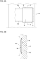
- the shoe 10 includes a restraining part 76 that restrains movement in the vertical directions of the medial bottom part 52 of the support member 50 with respect to the sole 12 but allows movement in the foot girth directions of the medial bottom part 52.
- the restraining part 76 in the present embodiment is constituted by a member provided separately from the sole 12 and made of a flexible material, such as a texture and a fabric.
- the restraining part 76 is fixed at its front edge part or rear edge part to the upper surface of the sole 12 by sewing or the like, forming an insertion passage 78 through which the medial bottom part 52 of the support member 50 is inserted, between the restraining part 76 and the sole 12. With the medial bottom part 52 of the support member 50 inserted through the insertion passage 78 formed by the restraining part 76, movement in the vertical directions of the medial bottom part 52 is restrained while movement in the foot girth directions of the medial bottom part 52 is allowed, as described previously.
- the medial bottom part 52 of the support member 50 is provided to be movable in the foot girth directions with respect to the sole 12.
- the medial bottom part 52 of the support member 50 includes a restrained region 80 provided on the lateral side in a foot width direction Y in the medial bottom part 52, and a movement allowable region 82 provided on the medial side in a foot width direction Y in the medial bottom part 52 with respect to the restrained region 80.
- the restrained region 80 movement in the vertical directions is restrained by the restraining part 76.
- the movement allowable region 82 movement in the vertical directions is not restrained by the restraining part 76, and a movable range in a vertical direction of the movement allowable region 82 is larger than that of the restrained region 80.
- the shoe 10 includes an arch support part 84.
- the arch support part 84 in the present embodiment is provided on the medial side in the medial bottom part 52 of the support member 50. It can also be said that the arch support part 84 is provided in the wide part 70 of the support member 50.
- the arch support part 84 is constituted by the movement allowable region 82 of the support member 50 and provided to be movable in the vertical directions with respect to the sole 12.
- the arch support part 84 is provided such that the tightening force Fa1 in the supination direction applied to the medial side portion 32 of the upper 14 can be transmitted thereto.
- the tightening force Fa1 in the supination direction is transmitted from the insertion parts 44 in the support member 50 provided in the medial side portion 32, through the support member 50 itself.
- the arch support part 84 is capable of supporting, from the underneath, a longitudinal arch A on the medial side in a foot width direction Y (the medial longitudinal arch) of the wearer's foot when tightening force is applied by the tightening tool 42 to the upper 14, as will be described later.
- the medial side portion 32 of the upper 14 includes a tightening force transmitter 86 provided on the medial side with respect to the arch support part 84.
- the tightening force transmitter 86 is provided such that the tightening force Fa1 in the supination direction applied to the medial side portion 32 can be transmitted thereto.
- the tightening force transmitter 86 in the present embodiment is constituted by a portion of the medial side portion 32 of the upper 14 located lower than the aforementioned lower through hole 58. To this portion of the medial side portion 32, the tightening force Fa1 in the supination direction applied as described previously is transmitted from the medial side part 54 of the support member 50 via an inner wall surface of the lower through hole 58.
- the stretchability in the foot girth directions of the tightening force transmitter 86 is set higher than that of the arch support part 84.
- the entire upper 14 is made of a material having higher stretchability in the foot girth directions, compared to the entire support member 50.
- the upper 14 may be made of Double Russel Mesh knitted from polyester yarn, and the support member 50 may be made of ether-based artificial leather, for example.
- FIG. 6 A case is considered in which the tightening tool 42 applies tightening force to the upper 14.
- the tightening force Fa1 in the supination direction is applied to the medial side portion 32 of the upper 14, and the tightening force Fa2 in the pronation direction is applied to the lateral side portion 34 of the upper 14.
- the tightening force Fa1 in the supination direction is applied to the medial side portion 32 of the upper 14, the tightening force Fa1 in the supination direction is transmitted to the arch support part 84, as described previously.
- the tightening force Fa1 in the supination direction allows the arch support part 84 to move in a vertical direction away from the sole 12 and to come into contact with the longitudinal arch A on the medial side from the underneath.
- the arch support part 84 applies upward force Fb1 in the supination direction to a position in contact with the longitudinal arch A and supports the longitudinal arch A on the medial side from the underneath.
- the arch support part 84 is disposed at a position that overlaps the midfoot portion of the upper 14 in side view, so as to support the midfoot portion on the medial side (the longitudinal arch on the medial side) of the foot.
- the medial bottom part 52 is provided to be movable in the foot girth directions with respect to the sole 12, the medial side part 54 is provided such that the tightening force Fa1 in the supination direction can be transmitted thereto, and the lateral side part 56 is fixed to the upper 14. Accordingly, when the tightening force Fa1 in the supination direction is transmitted to the medial side part 54 of the support member 50, the tightening force can be transmitted as downward force Fb2 in the supination direction to the lateral side portion 34 of the upper 14 via the medial bottom part 52 and the lateral side part 56 of the support member 50. With the downward force Fb2 in the supination direction applied from the upper 14 to the foot, excessive pronation in the pronation direction can be further restrained.
- the shoe may be configured such that the tightening force Fa2 in the pronation direction transmitted from the tightening tool 42 to the lateral side portion 34 of the support member 50 becomes smaller than the tightening force Fa1 in the supination direction transmitted from the tightening tool 42 to the medial side portion 32 of the support member 50.
- the present embodiment employs a structure in which the tightening tool insertion parts 44 are not provided in the other end 66 of the support member 50, as described below.
- tightening tool insertion parts 44 are provided in the one end 62 but are not provided in the other end 66. Accordingly, when the tightening tool 42 applies tightening force, the tightening force Fa1 in the supination direction is directly applied to the one end 62 of the support member 50, while the tightening force Fa2 in the pronation direction being directly applied to the other end 66 of the support member 50 can be prevented. This can avoid the situation where the tightening force Fa1 in the supination direction largely cancels out the tightening force Fa2 in the pronation direction, so that the downward force Fb2 in the supination direction can be effectively transmitted to the lateral side portion 34 of the upper 14 via the lateral side part 56 of the support member 50. Therefore, excessive pronation in the pronation direction can be further restrained.
- FIG. 4 is now referred to.
- the lower through hole 58 of the upper 14 in the present embodiment is provided higher than the aforementioned reference line L1. Accordingly, the insertion position of the support member 50 at the lower through hole 58 in the medial side portion 32 is made higher than the reference line L1, which can increase the contact range in a vertical direction between the arch support part 84 of the support member 50 and the foot. Therefore, the longitudinal arch A on the medial side can be firmly supported by the arch support part 84 more easily, so that excessive pronation in the pronation direction can be further restrained.
- FIGS. 4 and 7 are now referred to.
- the shoe 10 includes a restricting part 88 provided in the lateral side portion 34 of the upper 14.
- the restricting part 88 in the present embodiment is a cushion member 90 provided separately from the upper 14.
- the cushion member 90 is disposed between the outer layer member 22 and the inner layer member 20 of the upper 14.
- the cushion member 90 in the present embodiment may be formed in a rectangular shape in plan view, for example. In a non-deformed state, the cushion member 90 in the present embodiment has a cross section of rectangular shape perpendicular to a longitudinal direction of the cushion member 90.
- the restricting part 88 may be provided along the lateral side edge part 30 of the throat part 26, for example.
- the restricting part 88 may suitably be provided higher than the aforementioned reference line L1. More specifically, the lower end position of the restricting part 88 may suitably be provided higher than the aforementioned reference line L1.
- the restricting part 88 can restrict upward movement of the wearer's foot.
- the restricting part 88 in the present embodiment restricts the upward movement by means of repulsion caused by elastic deformation of the restricting part 88 itself.
- the restricting part 88 adjusts the repulsion of the cushion member 90 to bias, downward, the instep in the midfoot portion of the foot.
- the restricting part 88 is constituted by the cushion member 90, the restricting part 88 can be deformed to match the instep in shape, so that the area in the restricting part 88 in contact with the instep can be increased. Accordingly, the pressure applied to the instep through the restricting part 88 in the wearing state can be increased, so that excessive pronation in the pronation direction can be effectively restrained.
- the cushion member 90 constituting the restricting part 88 is disposed between the outer layer member 22 and the inner layer member 20, large asperities are less likely to occur in the accommodation room 18 formed by the inner layer member 20. Accordingly, the inner surface of the accommodation room 18 feels smooth for the foot accommodated in the accommodation room 18, providing a good fit.
- FIG. 4 is now referred to. Suitable positions of the restrained region 80 and the movement allowable region 82 in the medial bottom part 52 will be described.
- the shape of a cross section of the shoe 10 perpendicular to a longitudinal direction is considered.
- the dimension in a foot width direction Y of an upper surface part of the sole 12 is defined as Lc
- the position of 50% of Lc from an end 12a on the lateral side is defined as a first reference position 92
- the position of 65% of Lc from the end 12a on the lateral side is defined as a second reference position 94.
- the upper surface part of the sole 12 is divided in a foot width direction Y from the lateral side toward the medial side into a first region 96, a second region 98, and a third region 100.
- the first region 96 is a region extending from the end 12a on the lateral side to the first reference position 92.
- the second region 98 is a region extending from the first reference position 92 to the second reference position 94.
- the third region 100 is a region extending from the second reference position 94 to an end 12b on the medial side.
- a boundary position 102 between the restrained region 80 and the movement allowable region 82 in the medial bottom part 52 may suitably be located at a position that overlaps the second region 98 in a vertical direction.
- the restrained region 80 is provided at a position that overlaps, in a vertical direction, at least most of the first region 96 extending from the first reference position 92 toward the lateral side.
- the movement allowable region 82 is provided at a position that overlaps, in a medial direction, at least most of the third region 100 extending from the second reference position 94 toward the lateral side.
- the "most" as used herein means a range occupying 90 percent of the entire length in a foot width direction of the relevant region. This condition is set based on experimental findings. The reason will be described.
- the contact range between the foot F and the sole 12 changes variously because of a variety of causes.
- the "causes" include the type of the shoe, the type of the last used to make the shoe, and the position in a longitudinal direction of the foot, for example.
- the inventors have recognized that, in many cases, regardless of the influence of such causes, most of the contact range between the lateral side portion of the foot and the sole 12 is located in the first region 96, and the longitudinal arch on the medial side is positioned above the third region 100 with a space in between. This recognition has been obtained based on the aforementioned experimental findings. If upward force is applied to the contact range between the lateral side portion of the foot and the sole 12, force in the pronation direction will be unsuitably applied to the foot. Meanwhile, it is desirable that the longitudinal arch A on the medial side located above the third region 100 is supported from the underneath in as large a range as possible in a foot width direction Y.
- FIGS. 8-11 are now referred to.
- the shoe 10 according to the second embodiment will be described.
- the upper 14 includes a first upper constituent layer 110 that forms the accommodation room 18 for accommodating a foot, and a second upper constituent layer 112 disposed outside the first upper constituent layer 110.
- the first upper constituent layer 110 is provided as a layer for separating the inside and the outside of the upper 14, over the entire area in a longitudinal direction X and a foot width direction Y of the upper 14.
- the first upper constituent layer 110 has a multi-layered structure including the inner layer member 20 that forms the accommodation room 18, and the outer layer member 22 disposed outside the inner layer member 20.
- the second upper constituent layer 112 is provided only in an area of the upper 14 that occupies part of the range in a longitudinal direction X and part of the range in a foot width direction Y.
- the second upper constituent layer 112 is disposed such as to vertically cross the aforementioned reference line L1 on the medial side in a foot width direction Y.
- the second upper constituent layer 112 is provided only in the medial side portion 32 of the upper 14 as the "part of the range in a foot width direction Y".
- the second upper constituent layer 112 forms an exposed surface of the upper 14 that is exposed to the outside.
- the first upper constituent layer 110 also forms an exposed surface of the upper 14 exposed to the outside, in an area other than in the second upper constituent layer 112.
- a lower circumferential edge part of the first upper constituent layer 110 is fixed to the sole 12 by bonding, sewing, or the like.
- An outer circumferential edge part of the second upper constituent layer 112 is fixed to the first upper constituent layer 110 or the sole 12.
- a lower edge part of the second upper constituent layer 112 is fixed to the sole 12, and a front edge part, an upper edge part, and a rear edge part of the second upper constituent layer 112 are fixed to the first upper constituent layer 110.
- the wearing opening 24 and the throat part 26 of the upper 14 are provided on the first upper constituent layer 110. Also, the multiple insertion parts 44 are provided on the first upper constituent layer 110 itself in the medial side portion 32 and the lateral side portion 34 of the upper 14.
- the shoe 10 of the present embodiment does not include the support member 50 described in the first embodiment.
- the arch support part 84 in the present embodiment is provided in the first upper constituent layer 110.
- the arch support part 84 is provided on the inner side with respect to the second upper constituent layer 112.
- the tightening force Fa1 in the supination direction applied to the medial side portion 32 of the upper 14 is transmitted via the first upper constituent layer 110 itself.
- FIGS. 11 and 12 are now referred to.
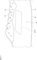
- FIG. 12 shows a fixed position of the arch support part 84 (the first upper constituent layer 110) to the upper surface part of the sole 12.
- FIG. 12 also shows, besides the upper surface part of the sole 12, a contact region 114 of the foot F with respect to the upper surface part of the sole 12.
- a lower edge part of the arch support part 84 is fixed to the sole 12 by bonding, sewing, or the like in the midfoot portion of the sole 12 and on the lateral side with respect to an edge part 12c on the medial side of the sole 12 in plan view such as to support the longitudinal arch A on the medial side.
- the arch support part 84 is provided in the midfoot portion in the medial side portion 32 of the upper 14.
- the tightening force transmitter 86 is provided in the second upper constituent layer 112, the tightening force transmitter 86 is provided.
- the entire second upper constituent layer 112 constitutes the tightening force transmitter 86.
- the stretchability in the foot girth directions of the tightening force transmitter 86 is set higher than that of the arch support part 84.
- the entire second upper constituent layer 112 is made of a material having higher stretchability in the foot girth directions, compared to the first upper constituent layer 110. Accordingly, also in the present embodiment, the effect previously described in (A) can be obtained.
- the first upper constituent layer 110 of the upper 14 serves dually as the arch support part 84, large asperities are less likely to occur in the accommodation room 18 formed by the first upper constituent layer 110. Accordingly, the inner surface of the accommodation room 18 feels smooth for the foot F accommodated in the accommodation room 18, providing a good fit.
- the shoe 10 of the present embodiment also includes the restricting part 88 constituted by the cushion member 90 similarly to the first embodiment. Also in the present embodiment, the aforementioned effects (D) and (E) can be obtained similarly to the first embodiment.
- FIG. 13 is now referred to.
- the shape of part of the upper 14 in plan view will be described.
- the multiple insertion parts 44 in the lateral side portion 34 of the upper 14 will be respectively given the characters "L1, L2..., L6" at the ends of the reference numerals thereof serially from the front side to the rear side.
- the multiple insertion parts 44 in the medial side portion 32 of the upper 14 will be respectively given the characters "M1, M2..., M6" at the ends of the reference numerals thereof serially from the front side to the rear side.
- the lateral side edge part 30 of the throat part 26 overall forms a contour projecting toward the medial side in a foot width direction Y, in a middle part 30a in a longitudinal direction.
- a convex end 120 constituted by the portion projecting toward the medial side in the contour is provided in the lateral side edge part 30.
- the convex end 120 is provided at a position closer to the medial side in a foot width direction Y with respect to both ends 30b and 30c in a longitudinal direction of the lateral side edge part 30.
- the aligned multiple insertion parts 44L1-44L6 provided in the lateral side portion 34 of the upper 14 include a first specific insertion part 44C (44L3) positioned closest to the medial side among the insertion parts, and a second specific insertion part 44D (44L4) positioned second closest to the medial side. These correspond to the insertion parts 44L3 and 44L4 positioned midway along a longitudinal direction X among the aligned multiple insertion parts 44L1-44L6.
- the first specific insertion part 44C (44L3) is positioned closer to the medial side with respect to the other insertion parts 44L1, 44L2, and 44L4-44L6.
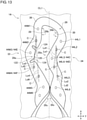
- the first specific insertion part 44C is provided at a position that overlaps the convex end 120 in a foot width direction Y.
- the second specific insertion part 44D is positioned next to the first specific insertion part 44C in a longitudinal direction X. In the present embodiment, the second specific insertion part 44D is positioned in the rear of the first specific insertion part 44C.
- a line externally tangent, from the medial side, to the two insertion parts 44L2 and 44L4 positioned next to the first specific insertion part 44C in the longitudinal directions will be referred to as a first external tangent Ld1, and a line connecting the centers C of the two insertion parts will be referred to as a first straight line Le1.
- the first specific insertion part 44C in the present embodiment is provided on the medial side with respect to the first external tangent Ld1.
- the first specific insertion part 44C in the present embodiment is also provided on the medial side with respect to the first straight line Le1.
- a line externally tangent, from the medial side, to the two insertion parts 44L2 and 44L5 positioned next to the pair of the first specific insertion part 44C and the second specific insertion part 44D in the longitudinal directions will be referred to as a second external tangent Ld2, and a line connecting the centers C of the two insertion parts will be referred to as a second straight line Le2.
- the pair of the first specific insertion part 44C and the second specific insertion part 44D in the present embodiment are provided on the medial side with respect to the second external tangent Ld2.
- the pair of the first specific insertion part 44C and the second specific insertion part 44D in the present embodiment are also provided on the medial side with respect to the second straight line Le2.
- the medial side edge part 28 of the throat part 26 overall forms a contour recessed toward the medial side in a foot width direction Y, in a middle part 28a in a longitudinal direction.
- a recess bottom part 122 constituted by the portion recessed toward the medial side in the contour is provided in the medial side edge part 28.
- the recess bottom part 122 is provided at a position closer to the medial side in a foot width direction Y with respect to both ends 28b and 28c in a longitudinal direction X of the medial side edge part 28.
- the convex end 120 in the lateral side edge part 30 and the recess bottom part 122 in the medial side edge part 28 are provided at positions such as to be aligned in a foot width direction Y.
- the aligned multiple insertion parts 44M1-44M6 provided in the medial side portion 32 of the upper 14 include a third specific insertion part 44E (44M3) positioned closest to the medial side among the insertion parts and a fourth specific insertion part 44F (44M4) positioned second closest to the medial side. These correspond to the insertion parts 44M3 and 44M4 positioned midway along a longitudinal direction X among the aligned multiple insertion parts 44M1-44M6.
- the third specific insertion part 44E (44M3) is positioned closer to the medial side with respect to the other insertion parts 44M1, 44M2, and 44M4-44M6.
- the third specific insertion part 44E is provided at a position that overlaps the recess bottom part 122 in a foot width direction Y.
- the fourth specific insertion part 44F is positioned next to the third specific insertion part 44E in a longitudinal direction X. In the present embodiment, the fourth specific insertion part 44F is positioned in the rear of the third specific insertion part 44E.
- a line externally tangent, from the medial side, to the two insertion parts 44M2 and 44M4 positioned next to the third specific insertion part 44E in the longitudinal directions will be referred to as a third external tangent Ld3, and a line connecting the centers C of the two insertion parts will be referred to as a third straight line Le3.
- the third specific insertion part 44E in the present embodiment is provided on the medial side with respect to the third external tangent Ld3.
- the third specific insertion part 44E in the present embodiment is also provided on the medial side with respect to the third straight line Le3.
- a line externally tangent, from the medial side, to the two insertion parts 44M2 and 44M5 positioned next to the pair of the third specific insertion part 44E and the fourth specific insertion part 44F in the longitudinal directions will be referred to as a fourth external tangent Ld4, and a line connecting the centers C of the two insertion parts will be referred to as a fourth straight line Le4.
- the pair of the third specific insertion part 44E and the fourth specific insertion part 44F in the present embodiment are provided on the medial side with respect to the fourth external tangent Ld4.
- the pair of the third specific insertion part 44E and the fourth specific insertion part 44F in the present embodiment are also provided on the medial side with respect to the fourth straight line Le4.
- the first specific insertion part 44C located midway along a longitudinal direction X is positioned closer to the medial side with respect to the other insertion parts 44 provided in the lateral side portion 34. Accordingly, compared to the case where the aligned multiple insertion parts 44L1-44L6 are positioned on a straight line, an area in the lateral side portion 34 of the upper 14 which is in contact with the instep and on which the tightening force by the tightening tool 42 acts can be increased. Therefore, designing for applying large force in the supination direction to the instep can be achieved more easily, and excessive pronation in the pronation direction can be further restrained. Such designing can be achieved by providing the cushion member 90 in the lateral side portion 34 of the upper 14, for example.
- the third specific insertion part 44E located midway along a longitudinal direction X is positioned closer to the medial side with respect to the other insertion parts 44 provided in the medial side portion 32. Accordingly, even when the first specific insertion part 44C provided in the lateral side portion 34 of the upper 14 is positioned closer to the medial side, the distance between the first specific insertion part 44C and the third specific insertion part 44E is less likely to be decreased. Therefore, when the tightening tool 42 is inserted through the insertion parts 44M1-44M6 and 44L1-44L6 in the medial side portion 32 and the lateral side portion 34 of the upper 14, the insertion work will be easier.
- a cut 124 recessed toward the medial side is formed between the insertion part 44M2 or 44M4 positioned next to the third specific insertion part 44E in a longitudinal direction X and the third specific insertion part 44E. It can be also said that a cut 124 is formed on a side in a longitudinal direction with respect to the recess bottom part 122 in the medial side edge part 28. In the present embodiment, the cut 124 is formed on each of the both sides in a longitudinal direction X with respect to the third specific insertion part 44E (recess bottom part 122) but may be formed on only one of the sides.
- the cuts 124 are formed only in a range that overlaps the decorative member 36 in a vertical direction in plan view. Accordingly, even when the contour of the medial side edge part 28 of the upper 14 is made to be recessed toward the medial side, flexibility of the medial side edge part 28 is favorable, providing a good fit.
- FIGS. 14-16 are now referred to.
- FIG. 16 shows a fixed position of the support member 50 to the upper surface part of the sole 12.
- the shoe 10 includes the support member 50 provided separately from the upper 14 and extending in a foot girth direction to form a strip shape.
- the support member 50 in the present embodiment is provided to extend in a foot girth direction along the medial side portion 32 of the upper 14.
- the one end 62 in a long side direction of the support member 50 is located in the medial side edge part 28 of the throat part 26 in the upper 14.
- an insertion part 44 is provided in the one end 62 of the support member 50.
- An insertion part 44 in the present embodiment is constituted by the one end 62 of the support member 50 wound in a loop shape.
- a portion of the support member 50 on the tip side with respect to the wound portion constituting an insertion part 44 is inserted through a through hole 130 formed in the medial side portion 32 of the upper 14 and is fixed to a circumferential edge part of the through hole 130 by bonding, sewing, or the like. Accordingly, the one end 62 of the support member 50 is fixed to the medial side portion 32 of the upper 14.
- multiple insertion parts 44 of the support member 50 are provided with a space in between along a longitudinal direction.
- the insertion parts 44 in the present embodiment include the first insertion part 44A on the front side, and the second insertion part 44B provided in the rear of the first insertion part 44A. In the present embodiment, between the first insertion part 44A and the second insertion part 44B, other insertion parts 44 directly provided in the medial side portion 32 of the upper 14 are not arranged.
- the support member 50 includes the wide part 70, and a narrow part 72 that extends from the wide part 70 to the one end side of the support member 50 and has a narrower width in a longitudinal direction than the wide part 70.
- Multiple narrow parts 72 of the support member 50 are provided with a space in between along a longitudinal direction.
- the wide part 70 in the present embodiment is provided to extend in a foot girth direction along the medial side portion 32 of the upper 14, and the narrow parts 72 are constituted by the aforementioned insertion parts 44.
- the arch support part 84 in the present embodiment is constituted by a partial area of the support member 50 extending from the other end 66 toward the one end side.
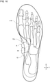
- the arch support part 84 in the present embodiment is provided in the wide part 70.
- the lower edge part of the arch support part 84 is fixed to the sole 12 by bonding, sewing, or the like in the midfoot portion of the sole 12 and on the lateral side with respect to the edge part 12c on the medial side of the sole 12 in plan view such as to support the longitudinal arch A on the medial side.
- the arch support part 84 is provided on the inner side with respect to the medial side portion 32 of the upper 14, at a position that overlaps the midfoot portion of the upper 14 in a foot width direction Y.
- the tightening force Fa1 in the supination direction is transmitted from the insertion parts 44 of the support member 50 provided in the medial side portion 32 of the upper 14 through the support member 50 itself.
- the upper 14 includes the tightening force transmitter 86 provided on the medial side with respect to the arch support part 84.
- the tightening force transmitter 86 in the present embodiment is constituted by a portion of the medial side portion 32 of the upper 14 located lower than each fixed position (sewn part S) of the support member 50 to the circumferential edge part of a through hole 130. To this portion, the tightening force Fa1 in the supination direction applied as described previously is transmitted via the support member 50.
- the stretchability in the foot girth directions of the tightening force transmitter 86 is also set higher than that of the arch support part 84.
- the entire upper 14 is made of a material having higher stretchability in the foot girth directions, compared to the entire support member 50. Accordingly, also in the present embodiment, the effect previously described in (A) can be obtained.
- the multiple insertion parts 44 of the support member 50 are provided with a space in between along a longitudinal direction. Accordingly, the effect previously described in (B) can be obtained.
- the multiple insertion parts 44 are provided respectively in the multiple narrow parts 72. Accordingly, the effect previously described in (C) can be obtained.
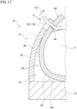
- FIGS. 17 and 18 are now referred to.
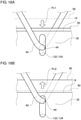
- FIGS. 18 are schematic diagrams that show states before and after the tightening force is applied to the support member 50 and also are diagrams viewed from the direction of arrow E shown in FIG. 17 .
- the shoe 10 of the present embodiment mainly differs in configurations of the upper 14 and the support member 50.
- the one end 62 in a long side direction of the support member 50 is located at a position where the support member 50 is disposed over the back of the medial side portion 32 of the upper 14.
- an insertion part 44 is provided in the one end 62 of the support member 50.
- the insertion part 44 in the support member 50 in the present embodiment is a through hole.
- another tightening tool insertion part 132 is provided at a position that overlaps the insertion part 44 in the support member 50.
- the tightening tool insertion part 132 in the upper 14 is a long hole 134 that is longer in a foot girth direction than the through hole constituted by the insertion part 44 in the support member 50.
- the tightening force transmitter 86 in the present embodiment is constituted by a portion of the medial side portion 32 of the upper 14 located lower than the lower through hole 58.
- the tightening force Fa1 in the supination direction applied to the support member 50 is released.
- the insertion part 44 and the arch support part 84 of the support member 50 have moved downward in a vertical direction with respect to the sole 12 (see the direction Pc1 in FIG. 18A ).
- the tightening tool 42 has also moved downward in conjunction with the support member 50, near the insertion position at the insertion part 44 in the support member 50 and within the long hole 134 in the medial side portion 32 of the upper 14. Accordingly, when the tightening tool 42 is loose, the tightening tool 42 is disposed at a position away from and below an upper inner wall surface of the long hole 134.
- the tightening force transmitter 86 in the present embodiment is configured such that, when the tightening tool 42 is being tightened, the tightening force is transmitted to the arch support part 84 before the tightening force transmitter 86. Accordingly, compared to the case where the tightening force is transmitted concurrently to the arch support part 84 and the tightening force transmitter 86, the tightening force can be transmitted to the arch support part 84 more easily. Accordingly, the amount of deformation of the tightening force transmitter 86 can be reduced, so that the repulsion caused by the deformation can also be reduced. Therefore, the tightening force transmitted to the arch support part 84 can be increased, so that the upward force in the supination direction applied from the arch support part 84 to the foot can also be increased.
- the longitudinal arch A on the medial side can be firmly supported by the arch support part 84 more easily, and lowering of the longitudinal arch A can be restrained, so that excessive pronation in the pronation direction can be restrained, as previously described in (A).
- the upper 14 may have a gusseted tongue structure.
- the gusseted tongue structure here means a structure in which the upper 14 and the shoe tongue 48 are formed integrally, and the upper 14 does not include the throat part 26.
- the medial side portion 32 of the upper 14 is constituted by a portion on the medial side with respect to the center line CL1 in the entire range in a longitudinal direction X.
- the lateral side portion 34 of the upper 14 is constituted by a portion on the lateral side with respect to the center line CL1 in the entire range in a longitudinal direction X.
- the number of insertion parts 44 in the support member 50 is not particularly limited and may also be one or three. Also, the support member 50 need not necessarily include the wide part 70 and the narrow parts 72. Further, the insertion parts 44 may be provided only in some of the multiple narrow parts 72.
- an insertion part 44 may be constituted by a through hole formed on part of the support member 50 placed over the back of the edge part 28 of the upper 14.
- the through holes 58 and 60 formed in the medial side portion 32 of the upper 14 in the first embodiment need not necessarily communicate with the inside and the outside of the upper 14.
- the through holes 58 and 60 are formed only in the inner layer member 20 and not formed in the outer layer member 22 in the upper 14.
- the medial side part 54 is provided such as to lie between the inner layer member 20 and the outer layer member 22 of the upper 14, in a range from the insertion position at the lower through hole 58 to the insertion position at the upper through hole 60.
- a specific example of the restraining part 76 is not particularly limited.
- the restraining part 76 may be provided only in part of the sole 12 in a foot width direction Y.
- the arch support part 84 has only to be provided such that the tightening force in the supination direction applied to the medial side portion 32 of the upper 14 can be transmitted thereto.
- part of the member (support member 50) constituting the arch support part 84 may be provided in the medial side portion 32 of the upper 14 so that the tightening force will be transmitted to the arch support part 84 via the member, as described in the first and third embodiments.
- the tightening force may be transmitted from the medial side portion 32 of the upper 14 to the arch support part 84 via the upper 14 itself, as described in the second embodiment.
- the tightening force transmitter 86 has only to be provided such that the tightening force in the supination direction applied to the medial side portion 32 of the upper 14 can be transmitted thereto.
- part of the member (support member 50) constituting the arch support part 84 may be provided in the medial side portion 32 of the upper 14 so that the tightening force will be transmitted to the tightening force transmitter 86 via the member, as described in the first and third embodiments.
- the tightening force may be transmitted from the medial side portion 32 of the upper 14 to the arch support part 86 via the upper 14 itself (the first upper constituent layer 110), as described in the second embodiment.
- the stretchability in the foot girth directions of the tightening force transmitter 86 has only to be set higher than that of the arch support part 84.
- the materials of the tightening force transmitter 86 and the arch support part 84 may be changed, as described in the first through third embodiments, or a stretchable region, such as an accordion structure, may be provided in part of the tightening force transmitter 86.
- the restricting part 88 has only to be provided in the medial side part 56 of the upper 14 to be capable of restricting upward movement of the foot, and it is not an essential to bias the instep downward.
- the restricting part 88 may be constituted by the cushion member 90 fixed further inside the inner layer member 20 of the upper 14, for example.
- the restricting part 88 may be constituted by the outer layer member 22 and the inner layer member 20 of the upper 14.
- the portion where the restricting part 88 is provided in the upper 14 is configured such that, in a non-deformed state, the dimension in a foot girth direction of the outer layer member 22 is larger than that of the inner layer member 20 in the upper 14.
- the inner layer member 20 is provided to be elastically stretched in a foot girth direction such as to match the outer layer member 22 in dimension in a foot girth direction.
- the second upper constituent layer 112 in the second embodiment is provided only in part of the entire range in a longitudinal direction of the upper 14, the second upper constituent layer 112 may be provided in the entire range. Also, although an example has been described in which the second upper constituent layer 112 is provided only in the medial side portion 32 of the upper 14, the second upper constituent layer 112 may be provided in the lateral side portion 34.
- both the edge parts 28 and 30 of the throat part 26 are not particularly limited in each embodiment. Also, even when the contour of the lateral side edge part 30 of the throat part 26 is made to project toward the medial side, the contour of the medial side edge part 28 may be made to extend linearly.
- the positional relationships among the multiple insertion parts 44 in the second embodiment may be applied to the multiple insertion parts 44 in the first, third, or fourth embodiment. Also, the positional relationships among the multiple insertion parts 44 in the first, third, or fourth embodiment may be applied to the multiple insertion parts 44 in the second embodiment.
- the support member 50 described in the first, third, or fourth embodiment may be used for the shoe 10 of the second embodiment.
- the upper constituent layers 110 and 112 described in the second embodiment may be used for the shoe 10 of the first or third embodiment.
- the support member 50 described in the first embodiment may be used, or the upper constituent layers 110 and 112 described in the second embodiment may be used.
- each of the aforementioned embodiments and modifications describes a shoe with which excessive pronation in the pronation direction can be restrained. Meanwhile, the present invention is also applicable to a shoe with which supination in the supination direction can be restrained.
- the description in the embodiments and modifications may be construed such as to satisfy the following conditions (1)-(3). In this case, it is construed that the first side of the foot width directions described previously is the lateral side, and the second side thereof is the medial side. Also, it is construed that the first side of the foot girth directions is the pronation direction, and the second side thereof is the supination direction.
- the arch support part 84 of the shoe 10 is provided such that the tightening force Fa2 in the pronation direction applied to the medial side portion 32 of the upper 14 can be transmitted thereto, so that the arch support part 84 can support, from the underneath, the wearer's longitudinal arch on the lateral side (lateral longitudinal arch).
- the tightening force transmitter 86 of the upper 14 is provided on the lateral side with respect to the arch support part 84 such that the tightening force in the pronation direction applied to the medial side portion 32 of the upper 14 can be transmitted thereto.
- the stretchability in the foot girth directions of the tightening force transmitter 86 has only to be set higher than that of the arch support part 84.
- the tightening force transmitter 86 of the upper 14 is more likely to be deformed, compared to the case where the stretchability of the tightening force transmitter 86 is made identical with the stretchability of the arch support part 84.
- This can increase the tightening force transmitted to the arch support part 84, thereby increasing the upward force in the pronation direction applied from the arch support part 84 to the foot.
- the longitudinal arch on the lateral side can be firmly supported by the arch support part 84 more easily, and lowering of the longitudinal arch can be restrained, so that supination in the supination direction can be restrained.
- the tightening force transmitter 86 may be configured such that, when the tightening tool 42 is being tightened, the tightening force is transmitted to the arch support part 84 before the tightening force transmitter 86, as is the case in the fourth embodiment.
- a shoe comprising:
- a tightening tool insertion part located midway along a longitudinal direction is positioned closer to the first side in the foot width direction with respect to the other tightening tool insertion parts.
- a purpose of the inventions described in the above items is to provide a shoe with which excessive pronation can be restrained.
- the present invention relates to a shoe.
Landscapes
- Health & Medical Sciences (AREA)
- Epidemiology (AREA)
- General Health & Medical Sciences (AREA)
- Public Health (AREA)
- Footwear And Its Accessory, Manufacturing Method And Apparatuses (AREA)
Abstract
Description
- The present invention relates to a shoe.
- In order to ensure the stability of running motion, preventing excessive pronation is desired. To achieve this, it is effective to prevent decrement of longitudinal arch heigh when the wearer's weight is applied to the foot. For example,
Patent Literature 1 describes a shoe in which a reinforcement member is disposed within the upper so as to prevent decrement of longitudinal arch heigh. - Patent Literature 1:
Japanese Unexamined Patent Application Publication No. 2016-36703 - The inventors have conducted study and gained the following new recognition. To restrain excessive pronation, there can be considered a method of providing, in a shoe, an arch support part to which tightening force of a tightening tool, such as a shoelace, is transmitted, so that the arch support part supports a longitudinal arch from the underneath. In this case, the arch support part is integrally formed with the upper, so that the tightening force to be applied to the arch support part may be dispersed and transmitted to the upper. This may cause large resistance in part of the upper other than the arch support part, so that the tightening force may not be sufficiently transmitted to the arch support part, which may therefore be unable to firmly support the longitudinal arch. With such a background issue, a shoe devised to restrain the lowering of a longitudinal arch has not been proposed.
- One aspect of the present invention has been made in view of such an issue, and a purpose thereof is to provide a shoe which can prevent decrement of longitudinal arch heigh of a foot.
- To solve the abovementioned issue, one aspect of the present invention relates to a shoe. The shoe includes: an upper; a tightening tool disposed above an instep of a wearer and capable of applying, to the upper, tightening force for drawing portions on the both sides in a foot width direction of the upper; and an arch support part provided such that tightening force applied to a first side portion in a foot width direction of the upper can be transmitted to the arch support part. The arch support part is also provided to be capable of supporting, from the underneath, a longitudinal arch on a first side in the foot width direction of a foot of a wearer. The first side portion includes a tightening force transmitter provided on the first side in the foot width direction with respect to the arch support part and also provided such that the tightening force applied to the first side portion can be transmitted to the tightening force transmitter. The tightening force transmitter has stretchability in foot girth directions set higher than that of the arch support part.
- To solve the abovementioned issue, another aspect of the present invention also relates to a shoe. The shoe includes: an upper; a tightening tool disposed above an instep of a wearer and capable of applying, to the upper, tightening force for drawing portions on the both sides in a foot width direction of the upper; and an arch support part provided such that tightening force applied to a first side portion in a foot width direction of the upper can be transmitted to the arch support part. The arch support part is also provided to be capable of supporting, from the underneath, a longitudinal arch on a first side in the foot width direction of a foot of a wearer. The first side portion includes a tightening force transmitter provided on the first side in the foot width direction with respect to the arch support part and also provided such that the tightening force applied to the first side portion can be transmitted to the tightening force transmitter. The tightening force transmitter is configured such that, when the tightening tool is being tightened, the tightening force is transmitted to the arch support part before the tightening force transmitter.
- With a shoe of the present invention, decrement of longitudinal arch heigh of a foot can be prevented.
-
-
FIG. 1 is a schematic plan view in which a skeleton model of a human foot is superimposed upon an inner bottom surface of an accommodation room within an upper; -
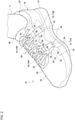
FIG. 2 is a schematic perspective view of a shoe according to a first embodiment viewed from a medial and front side of a foot; -
FIG. 3 is a schematic perspective view of the shoe according to the first embodiment viewed from a lateral and front side of a foot; -
FIG. 4 is a schematic diagram that illustrates a cross section perpendicular to a longitudinal direction of the shoe according to the first embodiment, viewed from a rear side; -
FIG. 5A is a schematic plan view of part of a sole with peripheral structure thereof in the first embodiment, andFIG. 5B is a sectional view taken along line A-A inFIG. 5A ; -
FIG. 6 is a diagram that schematically shows movements in the shoe according to the first embodiment; -
FIG. 7 is a schematic side view of the shoe viewed from the direction of arrow B inFIG. 4 ; -
FIG. 8 is a schematic perspective view of a shoe according to a second embodiment viewed from a medial and front side of a foot; -
FIG. 9 is a schematic perspective view of the shoe according to the second embodiment viewed from a lateral and front side of a foot; -
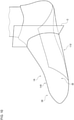
FIG. 10 is another schematic perspective view of part of the shoe according to the second embodiment viewed from a medial and front side of a foot; -
FIG. 11 is a schematic view of a cutting plane C shown inFIG. 10 , viewed from a rear side; -
FIG. 12 is a schematic plan view in which a skeleton model of a human foot is superimposed upon an upper surface part of the sole in the second embodiment; -
FIG. 13 is a schematic plan view of a throat part with peripheral structure thereof in the second embodiment; -
FIG. 14 is a schematic perspective view of part of a shoe according to a third embodiment viewed from a medial and front side of a foot; -
FIG. 15 is a schematic view of a cutting plane D shown inFIG. 14 , viewed from a rear side; -
FIG. 16 is a schematic plan view in which a skeleton model of a human foot is superimposed upon an upper surface part of the sole in the third embodiment; -
FIG. 17 is a schematic view of part of a shoe according to a fourth embodiment viewed from a rear side; and -
FIG. 18A is a schematic diagram that shows a state before tightening force is applied to a support member, andFIG. 18B is a schematic diagram that shows a state after the tightening force is applied to the support member. - In the following, exemplary embodiments of the present invention will be described. Like reference characters denote like constituting elements, and repetitive description will be omitted. In each drawing, part of the constituting elements may be appropriately omitted, or the size of a constituting element may be appropriately enlarged or reduced, for the sake of convenience. Each drawing is to be viewed according to the direction of the reference characters. With regard to "fixing" and "being in contact" in the present specification, besides the case where two subject components directly satisfy a relevant condition, the case where the two subject components satisfy the relevant condition via another member is also included, unless otherwise specified.
- Terms used in this specification will be described. With reference to
FIG. 1 , positional relationships in a plan view of ashoe 10 will be described.FIG. 1 is a plan view in which a skeleton model of a foot is superimposed upon aninner bottom surface 18a of anaccommodation room 18 within an upper 14. Here is assumed avirtual rectangle 16 of which the four sides circumscribe theinner bottom surface 18a of theaccommodation room 18 and of which a short side length La is minimum. A direction along a long side of thevirtual rectangle 16 is defined as a "longitudinal direction X", and a direction along a short side thereof is defined as a "foot width direction Y". In a "longitudinal direction X", the front side is defined as the toe side of the foot, and the rear side is defined as the heel side of the foot. In a "foot width direction Y", the medial side is defined as the first toe side of the foot, and the lateral side is defined as the fifth toe side of the foot. When here is assumed a straight line passing through a midpoint N3 between the center N1 of the thenar eminence and the center N2 of the hypothenar eminence and through the center N4 of the heel, a "longitudinal direction X" also corresponds to a direction assumed to be parallel with the straight line. Also, a direction of circling around the axis of the longitudinal direction X is defined as a "foot girth direction". Further, a line extending along a longitudinal direction X and passing through a position that bisects the aforementioned short side length La of thevirtual rectangle 16 will be referred to as a "center line CL1" of theshoe 10. - A human foot is mainly constituted by cuneiform bones Ba, a cuboid bone Bb, a navicular bone Bc, a talus Bd, a calcaneus Be, metatarsal bones Bf, and phalanges Bg. Joints of a foot include MP joints Ja, Lisfranc joints Jb, and a Chopart's joint Jc.
- A "midfoot portion of a foot" means a portion from the MP joints Ja to the Chopart's joint Jc. A "longitudinal arch" of a foot means either a "medial longitudinal arch" or a "lateral longitudinal arch". The "medial longitudinal arch" means a region within a range from the calcaneus Be through the talus Bd, the navicular bone Bc, and the medial cuneiform bone Ba to the thenar eminence of the first metatarsal bone Bf on the medial side of a foot. The "lateral longitudinal arch" means a region within a range from the calcaneus Be through the cuboid bone Bb to the hypothenar eminence of the fifth metatarsal bone Bf on the lateral side of a foot.
- The "midfoot portion" in terms of a constituting element of a shoe means a region assumed to be overlapped by the midfoot portion of a foot in plan view. A line P represents a straight line extending along a foot width direction Y and positioned within a range S1 from 50% to 75% of the entire length Lb of the
shoe 10 from the heel side. A line Q represents a straight line extending along a foot width direction Y and positioned within a range S2 from 20% to 45% of the entire length Lb of theshoe 10 from the heel side. In this case, the "midfoot portion" in terms of a constituting element of a shoe means a region between the line P and the line Q in plan view. - The following embodiments describe examples in which the medial side is defined as a first side of the both foot width directions, and the lateral side is defined as a second side thereof. Also, the embodiments describe examples in which a supination direction is defined as a first side of the both foot girth directions, and a pronation direction is defined as a second side thereof. Each embodiment describes a shoe with which excessive pronation in the pronation direction can be prevented.
-
FIGS. 2-4 are now referred to. Theshoe 10 according to the first embodiment will be described. Although a shoe for a right foot is illustrated, the following description is also applicable to a shoe for a left foot. Theshoe 10 is used for running, for example. The running includes, besides the motion of running on general road surfaces, running motion in track and field, such as sprints, or ball sports and also includes walking motion. - The
shoe 10 includes a sole 12 that supports a foot F of a wearer. The sole 12 in the present embodiment includes an outsole to be in contact with the ground. Besides the outsole, the sole 12 may also include one or more of a midsole, an insole, and an inner sole, which are laminated above the outsole, for example. - The
shoe 10 also includes an upper 14 that wraps the foot F of the wearer. The upper 14 forms theaccommodation room 18 that accommodates a foot between the upper 14 and the sole 12. The upper 14 covers a range from the toe to part of the instep of a foot from the above, covers a range from the toe to the heel of the foot from the both sides in a foot width direction Y, and covers the heel from the rear side. A lower circumferential edge part of the upper 14 is fixed to the sole 12 by bonding, sewing, or the like. - The upper 14 may be made of a material such as a texture and a fabric, or a leather material such as synthetic leather and artificial leather, for example. For the upper 14, a flexible material that matches a foot in shape is used. The upper 14 of the present embodiment has a multi-layered structure including an
inner layer member 20 that forms theaccommodation room 18, and anouter layer member 22 disposed outside theinner layer member 20. - On the upper 14, a wearing
opening 24 is formed as a first opening that opens upward in a rear part of the upper 14. In a state where a wearer wears the shoe 10 (hereinafter, simply referred to as a wearing state), through the wearingopening 24, part of a foot, such as the ankle of the foot F, is inserted. - On the upper 14, a
throat part 26 is formed as a second opening that continues to the wearingopening 24 and extends frontward from the wearingopening 24. Thethroat part 26 includes a medial side edge part 28 (a first side edge part) provided on the medial side in a foot width direction Y, and a lateral side edge part 30 (a second side edge part) provided on the lateral side. Each of theedge parts throat part 26. - The upper 14 includes a medial side portion 32 (a first side portion) provided on the medial side in a foot width direction Y, and a lateral side portion 34 (a second side portion) provided on the lateral side in a foot width direction Y. The
medial side portion 32 in the present embodiment is constituted by a portion located lower than the medialside edge part 28 of thethroat part 26 in a longitudinal range in which thethroat part 26 is provided and by a portion located on the medial side with respect to the aforementioned center line CL1, not illustrated, in a longitudinal range other than the longitudinal range in which thethroat part 26 is provided. Thelateral side portion 34 is constituted by a portion located lower than the lateralside edge part 30 of thethroat part 26 in a longitudinal range in which thethroat part 26 is provided and by a portion located on the lateral side with respect to the center line CL1, not illustrated, in a longitudinal range other than the longitudinal range in which thethroat part 26 is provided. - The
shoe 10 of the present embodiment includes adecorative member 36 fixed to thethroat part 26. Thedecorative member 36 is provided along thethroat part 26 continuously from the front end of thethroat part 26 through theedge parts opening 24. Thedecorative member 36 may be made of a tape material or artificial leather, for example. Thedecorative member 36 is made of a material having lower stretchability than the upper 14 and is fixed to the upper 14 by bonding, sewing, or the like. - On a cross section perpendicular to a longitudinal direction X of the upper 14, a position located closest to the medial side is defined as a most
medial end 38, a position located closest to the lateral side is defined as a mostlateral end 40, and a straight line passing through the mostmedial end 38 and the mostlateral end 40 will be referred to as a "reference line L1". - The
shoe 10 includes atightening tool 42 disposed above the instep of the wearer. With the tighteningtool 42, tightening force for drawing themedial side portion 32 and thelateral side portion 34 of the upper 14 can be applied to the upper 14. The tighteningtool 42 applies tightening force Fa1 in the supination direction to themedial side portion 32 of the upper 14 and applies tightening force Fa2 in the pronation direction to thelateral side portion 34 of the upper 14. The tighteningtool 42 in the present embodiment applies the tightening force Fa1 in the supination direction to the medialside edge part 28 of thethroat part 26 and applies the tightening force Fa2 in the pronation direction to the lateralside edge part 30 of thethroat part 26. With the tightening force applied by the tighteningtool 42, the upper 14 can fit onto the foot. Although thetightening tool 42 in the present embodiment is a shoelace, a specific example of the tighteningtool 42 is not particularly limited as long as it can apply the tightening force, and the tighteningtool 42 may be a belt, a wire, or the like. - On the
portions tightening tool 42 is inserted is provided. In the present embodiment,multiple insertion parts 44 are aligned with a space in between along a longitudinal direction, in each of themedial side portion 32 and thelateral side portion 34 of the upper 14. In the present embodiment, theinsertion parts 44 are provided in theedge parts throat part 26. Although theinsertion parts 44 in the present embodiment are through holes through which thetightening tool 42 is inserted, theinsertion parts 44 may also be grommets, shoelace hooks, or the like. - In the present embodiment, some of the
insertion parts 44 are directly provided in themedial side portion 32 and thelateral side portion 34 of the upper 14, and other some of theinsertion parts 44 are provided in a member (asupport member 50 described later) separate from the upper 14 in themedial side portion 32. Theinsertion parts 44 provided directly in each of theportions decorative member 36. One end portion of the tighteningtool 42 is inserted alternately through theinsertion parts 44 in themedial side portion 32 and theinsertion parts 44 in thelateral side portion 34 such as to be inserted through everyother insertion part 44 in each of the alignments ofmultiple insertion parts 44. The other end portion of the tighteningtool 42 is also inserted alternately through theinsertion parts 44 in themedial side portion 32 and theinsertion parts 44 in thelateral side portion 34 such as to be inserted through everyother insertion part 44 in each of the alignments ofmultiple insertion parts 44. - The
shoe 10 of the present embodiment includes ashoe tongue 48 provided such as to cover thethroat part 26 in plan view. A front end of theshoe tongue 48 is fixed to the front end of thethroat part 26 by sewing or the like, and a rear end of theshoe tongue 48 is a free end movable with respect to the upper 14. - The
shoe 10 includes thesupport member 50 provided separately from the upper 14 and extending in a foot girth direction to form a strip shape. Thesupport member 50 includes a medialbottom part 52 disposed between the foot and the sole 12, a medial side part 54 (a first side part) provided on the medial side in a foot width direction Y with respect to the medialbottom part 52, and a lateral side part 56 (a second side part) provided on the lateral side in a foot width direction Y with respect to the medialbottom part 52. - The
medial side part 54 of thesupport member 50 is provided to extend in a foot girth direction along themedial side portion 32 of the upper 14. On themedial side portion 32 of the upper 14, a lower throughhole 58 and an upper throughhole 60, which open on the inner surface of theaccommodation room 18, are formed at positions vertically spaced away from each other. Each of the throughholes medial side part 54 in the present embodiment is movably inserted through the lower throughhole 58 and the upper throughhole 60 of the upper 14. Toward its tip side, themedial side part 54 is provided such as to protrude from the lower throughhole 58 of the upper 14 to the outside of theaccommodation room 18 and to protrude from the upper throughhole 60 of the upper 14 to the inside of theaccommodation room 18. Themedial side part 54 in the present embodiment is provided such as to be exposed to external space, in a range from the insertion position at the lower throughhole 58 to the insertion position at the upper throughhole 60. A tip part of themedial side part 54 in the present embodiment is disposed on the medialside edge part 28 of thethroat part 26. - One
end 62 in a long side direction of thesupport member 50 is located in the tip part of themedial side part 54. The oneend 62 of thesupport member 50 in the present embodiment is disposed higher than the aforementioned reference line L1. Themedial side part 54 of thesupport member 50 is disposed on the medial side in a foot width direction Y such as to vertically cross the reference line L1. Themedial side part 54 is provided such that the tightening force Fa1 in the supination direction applied by the tighteningtool 42 can be transmitted thereto. To achieve this, one of the aforementionedmultiple insertion parts 44 is provided in the tip part of themedial side part 54, i.e., in the oneend 62 of thesupport member 50. - In the present embodiment,
multiple insertion parts 44 are provided in thesupport member 50 with a space in between along a longitudinal direction. Theseinsertion parts 44 in the present embodiment include afirst insertion part 44A on the front side, and asecond insertion part 44B provided in the rear of thefirst insertion part 44A. In the present embodiment, between thefirst insertion part 44A and thesecond insertion part 44B,other insertion parts 44 directly provided in themedial side portion 32 of the upper 14 are arranged. Theinsertion parts 44 in thesupport member 50 constitute at least some of the alignedmultiple insertion parts 44 provided in themedial side portion 32. - The
lateral side part 56 of thesupport member 50 is provided to extend in a foot girth direction along thelateral side portion 34 of the upper 14. In the present embodiment, aslit 64 is formed in theinner layer member 20 in thelateral side portion 34 of the upper 14. Through theslit 64, thelateral side part 56 of thesupport member 50 is inserted between theouter layer member 22 and theinner layer member 20 of the upper 14. Thelateral side part 56 of thesupport member 50 is provided such as not to be exposed to external space. Thelateral side part 56 of thesupport member 50 is provided to cover the lateral side portion of the instep from the above in the wearing state. - The
other end 66 in a long side direction of thesupport member 50 is located in the tip part of thelateral side part 56. Theother end 66 of thesupport member 50 in the present embodiment is disposed higher than the aforementioned reference line L1. Thelateral side part 56 of thesupport member 50 is disposed on the lateral side in a foot width direction Y such as to vertically cross the reference line L1. In the present embodiment, part of thelateral side part 56 of thesupport member 50 is disposed at a position that overlaps the lateralside edge part 30 of thethroat part 26 and fixed to the lateralside edge part 30 by sewing or the like. Thelateral side part 56 is fixed to the upper 14 at a position higher than the reference line L1. Unlike the oneend 62 of thesupport member 50, in theother end 66 of thesupport member 50, the tighteningtool insertion parts 44 are not provided. - The
support member 50 includes awide part 70, and anarrow part 72 that extends from thewide part 70 to the one end side of thesupport member 50 and has a narrower width in a longitudinal direction than thewide part 70. In the present embodiment, thewide part 70 is constituted by the medialbottom part 52 of thesupport member 50, and thenarrow part 72 is constituted by themedial side part 54 of thesupport member 50. There are provided multiplenarrow parts 72 of thesupport member 50 with a space in between along a longitudinal direction. Thenarrow parts 72 in the present embodiment include a firstnarrow part 72A on the front side, and a secondnarrow part 72B provided in the rear of the firstnarrow part 72A. Themultiple insertion parts narrow parts -
FIGS. 4 and5 are now referred to. The "S" in the drawings indicates a sewn part. Theshoe 10 includes a restrainingpart 76 that restrains movement in the vertical directions of the medialbottom part 52 of thesupport member 50 with respect to the sole 12 but allows movement in the foot girth directions of the medialbottom part 52. The restrainingpart 76 in the present embodiment is constituted by a member provided separately from the sole 12 and made of a flexible material, such as a texture and a fabric. The restrainingpart 76 is fixed at its front edge part or rear edge part to the upper surface of the sole 12 by sewing or the like, forming aninsertion passage 78 through which the medialbottom part 52 of thesupport member 50 is inserted, between the restrainingpart 76 and the sole 12. With the medialbottom part 52 of thesupport member 50 inserted through theinsertion passage 78 formed by the restrainingpart 76, movement in the vertical directions of the medialbottom part 52 is restrained while movement in the foot girth directions of the medialbottom part 52 is allowed, as described previously. The medialbottom part 52 of thesupport member 50 is provided to be movable in the foot girth directions with respect to the sole 12. - The medial
bottom part 52 of thesupport member 50 includes arestrained region 80 provided on the lateral side in a foot width direction Y in the medialbottom part 52, and a movementallowable region 82 provided on the medial side in a foot width direction Y in the medialbottom part 52 with respect to the restrainedregion 80. In therestrained region 80, movement in the vertical directions is restrained by the restrainingpart 76. In the movementallowable region 82, movement in the vertical directions is not restrained by the restrainingpart 76, and a movable range in a vertical direction of the movementallowable region 82 is larger than that of the restrainedregion 80. - The description now returns to
FIGS. 2-4 . Theshoe 10 includes anarch support part 84. Thearch support part 84 in the present embodiment is provided on the medial side in the medialbottom part 52 of thesupport member 50. It can also be said that thearch support part 84 is provided in thewide part 70 of thesupport member 50. Thearch support part 84 is constituted by the movementallowable region 82 of thesupport member 50 and provided to be movable in the vertical directions with respect to the sole 12. Thearch support part 84 is provided such that the tightening force Fa1 in the supination direction applied to themedial side portion 32 of the upper 14 can be transmitted thereto. To thearch support part 84 in the present embodiment, the tightening force Fa1 in the supination direction is transmitted from theinsertion parts 44 in thesupport member 50 provided in themedial side portion 32, through thesupport member 50 itself. Thearch support part 84 is capable of supporting, from the underneath, a longitudinal arch A on the medial side in a foot width direction Y (the medial longitudinal arch) of the wearer's foot when tightening force is applied by the tighteningtool 42 to the upper 14, as will be described later. - The
medial side portion 32 of the upper 14 includes a tighteningforce transmitter 86 provided on the medial side with respect to thearch support part 84. The tighteningforce transmitter 86 is provided such that the tightening force Fa1 in the supination direction applied to themedial side portion 32 can be transmitted thereto. To achieve this, the tighteningforce transmitter 86 in the present embodiment is constituted by a portion of themedial side portion 32 of the upper 14 located lower than the aforementioned lower throughhole 58. To this portion of themedial side portion 32, the tightening force Fa1 in the supination direction applied as described previously is transmitted from themedial side part 54 of thesupport member 50 via an inner wall surface of the lower throughhole 58. - The stretchability in the foot girth directions of the tightening
force transmitter 86 is set higher than that of thearch support part 84. In the present embodiment, the entire upper 14 is made of a material having higher stretchability in the foot girth directions, compared to theentire support member 50. To achieve this, the upper 14 may be made of Double Russel Mesh knitted from polyester yarn, and thesupport member 50 may be made of ether-based artificial leather, for example. - There will be described the operation of the
shoe 10 set forth above.FIG. 6 is now referred to. A case is considered in which thetightening tool 42 applies tightening force to the upper 14. The tightening force Fa1 in the supination direction is applied to themedial side portion 32 of the upper 14, and the tightening force Fa2 in the pronation direction is applied to thelateral side portion 34 of the upper 14. - When the tightening force Fa1 in the supination direction is applied to the
medial side portion 32 of the upper 14, the tightening force Fa1 in the supination direction is transmitted to thearch support part 84, as described previously. The tightening force Fa1 in the supination direction allows thearch support part 84 to move in a vertical direction away from the sole 12 and to come into contact with the longitudinal arch A on the medial side from the underneath. At the time, thearch support part 84 applies upward force Fb1 in the supination direction to a position in contact with the longitudinal arch A and supports the longitudinal arch A on the medial side from the underneath. Thearch support part 84 is disposed at a position that overlaps the midfoot portion of the upper 14 in side view, so as to support the midfoot portion on the medial side (the longitudinal arch on the medial side) of the foot. - When the tightening force Fa1 in the supination direction is thus applied to the
medial side portion 32 of the upper 14, the tightening force Fa1 in the supination direction is transmitted to the tighteningforce transmitter 86 of the upper 14, as described previously. - There will be described effects provided by the
shoe 10 set forth above. - (A) The tightening
force transmitter 86 of the upper 14 is made of a material having higher stretchability than the material of thearch support part 84. Accordingly, when the tightening force Fa1 in the supination direction is applied to themedial side portion 32 of the upper 14, the tighteningforce transmitter 86 of the upper 14 is more likely to be deformed, compared to the case where the stretchability of the tighteningforce transmitter 86 is made identical with the stretchability of thearch support part 84. This can increase the tightening force transmitted to thearch support part 84, thereby increasing the upward force in the supination direction applied from thearch support part 84 to the foot. As a result, the longitudinal arch A on the medial side can be firmly supported by thearch support part 84 more easily, and lowering of the longitudinal arch A can be restrained, so that excessive pronation in the pronation direction can be restrained. - (B) The
multiple insertion parts 44 in thesupport member 50 are provided with a space in between along a longitudinal direction. Accordingly, thearch support part 84 of thesupport member 50 can also be structured to extend in a large area in a longitudinal direction. Therefore, with thearch support part 84 of thesupport member 50, a large area of the longitudinal arch A on the medial side can be supported. - (C)
Multiple insertion parts 44 are provided respectively in the multiplenarrow parts 72. Accordingly, thearch support part 84 of thesupport member 50 can also be structured such that thewide part 70 of thesupport member 50 extends in a large area in a longitudinal direction. Therefore, with thearch support part 84 of thesupport member 50, a large area of the longitudinal arch A on the medial side can be supported. - In the
support member 50, the medialbottom part 52 is provided to be movable in the foot girth directions with respect to the sole 12, themedial side part 54 is provided such that the tightening force Fa1 in the supination direction can be transmitted thereto, and thelateral side part 56 is fixed to the upper 14. Accordingly, when the tightening force Fa1 in the supination direction is transmitted to themedial side part 54 of thesupport member 50, the tightening force can be transmitted as downward force Fb2 in the supination direction to thelateral side portion 34 of the upper 14 via the medialbottom part 52 and thelateral side part 56 of thesupport member 50. With the downward force Fb2 in the supination direction applied from the upper 14 to the foot, excessive pronation in the pronation direction can be further restrained. - To obtain the effects described above, the shoe may be configured such that the tightening force Fa2 in the pronation direction transmitted from the tightening
tool 42 to thelateral side portion 34 of thesupport member 50 becomes smaller than the tightening force Fa1 in the supination direction transmitted from the tighteningtool 42 to themedial side portion 32 of thesupport member 50. To satisfy this condition, the present embodiment employs a structure in which the tighteningtool insertion parts 44 are not provided in theother end 66 of thesupport member 50, as described below. - In the
support member 50, tighteningtool insertion parts 44 are provided in the oneend 62 but are not provided in theother end 66. Accordingly, when the tighteningtool 42 applies tightening force, the tightening force Fa1 in the supination direction is directly applied to the oneend 62 of thesupport member 50, while the tightening force Fa2 in the pronation direction being directly applied to theother end 66 of thesupport member 50 can be prevented. This can avoid the situation where the tightening force Fa1 in the supination direction largely cancels out the tightening force Fa2 in the pronation direction, so that the downward force Fb2 in the supination direction can be effectively transmitted to thelateral side portion 34 of the upper 14 via thelateral side part 56 of thesupport member 50. Therefore, excessive pronation in the pronation direction can be further restrained. - In the
restrained region 80 provided on the lateral side in the medialbottom part 52, movement in the vertical directions is restrained by the restrainingpart 76. Accordingly, upward force in the pronation direction is less likely to be applied from the restrainedregion 80 on the lateral side in the medialbottom part 52 to the foot F. Accordingly, the force Fb1 in the supination direction is applied from thearch support part 84 provided in the movementallowable region 82 of the medialbottom part 52 to the foot F, while a situation can be avoided in which force in the pronation direction is applied from the restrainedregion 80 of the medialbottom part 52 to the foot F. Therefore, excessive pronation in the pronation direction can be further restrained. - Other features of the
shoe 10 according to the first embodiment will be described. -
FIG. 4 is now referred to. The lower throughhole 58 of the upper 14 in the present embodiment is provided higher than the aforementioned reference line L1. Accordingly, the insertion position of thesupport member 50 at the lower throughhole 58 in themedial side portion 32 is made higher than the reference line L1, which can increase the contact range in a vertical direction between thearch support part 84 of thesupport member 50 and the foot. Therefore, the longitudinal arch A on the medial side can be firmly supported by thearch support part 84 more easily, so that excessive pronation in the pronation direction can be further restrained. -
FIGS. 4 and7 are now referred to. Theshoe 10 includes a restrictingpart 88 provided in thelateral side portion 34 of the upper 14. The restrictingpart 88 in the present embodiment is a cushion member 90 provided separately from the upper 14. The cushion member 90 is disposed between theouter layer member 22 and theinner layer member 20 of the upper 14. The cushion member 90 in the present embodiment may be formed in a rectangular shape in plan view, for example. In a non-deformed state, the cushion member 90 in the present embodiment has a cross section of rectangular shape perpendicular to a longitudinal direction of the cushion member 90. - The restricting
part 88 may be provided along the lateralside edge part 30 of thethroat part 26, for example. The restrictingpart 88 may suitably be provided higher than the aforementioned reference line L1. More specifically, the lower end position of the restrictingpart 88 may suitably be provided higher than the aforementioned reference line L1. - In the state where the longitudinal arch A on the medial side is supported by the
arch support part 84, the restrictingpart 88 can restrict upward movement of the wearer's foot. In this state, the restrictingpart 88 in the present embodiment restricts the upward movement by means of repulsion caused by elastic deformation of the restrictingpart 88 itself. The restrictingpart 88 adjusts the repulsion of the cushion member 90 to bias, downward, the instep in the midfoot portion of the foot. - (D) Accordingly, when the wearer's foot is to move in the pronation direction, such movement can be restricted by the restricting
part 88, so that excessive pronation in the pronation direction can be further restrained. - (E) Particularly, since the restricting
part 88 biases the instep downward, movement of the wearer's foot in the pronation direction can be restrained, so that excessive pronation in the pronation direction can be further restrained. - Since the restricting
part 88 is constituted by the cushion member 90, the restrictingpart 88 can be deformed to match the instep in shape, so that the area in the restrictingpart 88 in contact with the instep can be increased. Accordingly, the pressure applied to the instep through the restrictingpart 88 in the wearing state can be increased, so that excessive pronation in the pronation direction can be effectively restrained. - Since the cushion member 90 constituting the restricting
part 88 is disposed between theouter layer member 22 and theinner layer member 20, large asperities are less likely to occur in theaccommodation room 18 formed by theinner layer member 20. Accordingly, the inner surface of theaccommodation room 18 feels smooth for the foot accommodated in theaccommodation room 18, providing a good fit. -
FIG. 4 is now referred to. Suitable positions of the restrainedregion 80 and the movementallowable region 82 in the medialbottom part 52 will be described. The shape of a cross section of theshoe 10 perpendicular to a longitudinal direction is considered. The dimension in a foot width direction Y of an upper surface part of the sole 12 is defined as Lc, the position of 50% of Lc from anend 12a on the lateral side is defined as afirst reference position 92, and the position of 65% of Lc from theend 12a on the lateral side is defined as asecond reference position 94. The upper surface part of the sole 12 is divided in a foot width direction Y from the lateral side toward the medial side into afirst region 96, asecond region 98, and athird region 100. Thefirst region 96 is a region extending from theend 12a on the lateral side to thefirst reference position 92. Thesecond region 98 is a region extending from thefirst reference position 92 to thesecond reference position 94. Thethird region 100 is a region extending from thesecond reference position 94 to anend 12b on the medial side. - In this case, a boundary position 102 between the
restrained region 80 and the movementallowable region 82 in the medialbottom part 52 may suitably be located at a position that overlaps thesecond region 98 in a vertical direction. When this condition is satisfied, therestrained region 80 is provided at a position that overlaps, in a vertical direction, at least most of thefirst region 96 extending from thefirst reference position 92 toward the lateral side. Also, when this condition is satisfied, the movementallowable region 82 is provided at a position that overlaps, in a medial direction, at least most of thethird region 100 extending from thesecond reference position 94 toward the lateral side. The "most" as used herein means a range occupying 90 percent of the entire length in a foot width direction of the relevant region. This condition is set based on experimental findings. The reason will be described. - The contact range between the foot F and the sole 12 changes variously because of a variety of causes. The "causes" include the type of the shoe, the type of the last used to make the shoe, and the position in a longitudinal direction of the foot, for example. The inventors have recognized that, in many cases, regardless of the influence of such causes, most of the contact range between the lateral side portion of the foot and the sole 12 is located in the
first region 96, and the longitudinal arch on the medial side is positioned above thethird region 100 with a space in between. This recognition has been obtained based on the aforementioned experimental findings. If upward force is applied to the contact range between the lateral side portion of the foot and the sole 12, force in the pronation direction will be unsuitably applied to the foot. Meanwhile, it is desirable that the longitudinal arch A on the medial side located above thethird region 100 is supported from the underneath in as large a range as possible in a foot width direction Y. - When the boundary position between the
restrained region 80 and the movementallowable region 82 in the medialbottom part 52 satisfies the aforementioned condition, a situation can be avoided in which force in the pronation direction is applied to the contact range between the lateral side portion of the foot and the sole 12, compared to the case where the boundary position is located at a position that overlaps thefirst region 96 in a vertical direction. Also, when this condition is satisfied, a large range in a foot width direction of the longitudinal arch A on the medial side located above thethird region 100 can be supported from the underneath by thearch support part 84 provided in the movementallowable region 82, compared to the case where the boundary position is located in thethird region 100. As a result, regardless of the influence of the various causes mentioned previously, a situation can be avoided in which force in the pronation direction is applied to the foot, while a large range of the longitudinal arch A on the medial side can be stably supported by thearch support part 84. -
FIGS. 8-11 are now referred to. Theshoe 10 according to the second embodiment will be described. The upper 14 includes a first upperconstituent layer 110 that forms theaccommodation room 18 for accommodating a foot, and a second upperconstituent layer 112 disposed outside the first upperconstituent layer 110. The first upperconstituent layer 110 is provided as a layer for separating the inside and the outside of the upper 14, over the entire area in a longitudinal direction X and a foot width direction Y of the upper 14. The first upperconstituent layer 110 has a multi-layered structure including theinner layer member 20 that forms theaccommodation room 18, and theouter layer member 22 disposed outside theinner layer member 20. - The second upper
constituent layer 112 is provided only in an area of the upper 14 that occupies part of the range in a longitudinal direction X and part of the range in a foot width direction Y. The second upperconstituent layer 112 is disposed such as to vertically cross the aforementioned reference line L1 on the medial side in a foot width direction Y. The second upperconstituent layer 112 is provided only in themedial side portion 32 of the upper 14 as the "part of the range in a foot width direction Y". The second upperconstituent layer 112 forms an exposed surface of the upper 14 that is exposed to the outside. The first upperconstituent layer 110 also forms an exposed surface of the upper 14 exposed to the outside, in an area other than in the second upperconstituent layer 112. - A lower circumferential edge part of the first upper
constituent layer 110 is fixed to the sole 12 by bonding, sewing, or the like. An outer circumferential edge part of the second upperconstituent layer 112 is fixed to the first upperconstituent layer 110 or the sole 12. In the present embodiment, a lower edge part of the second upperconstituent layer 112 is fixed to the sole 12, and a front edge part, an upper edge part, and a rear edge part of the second upperconstituent layer 112 are fixed to the first upperconstituent layer 110. - The wearing
opening 24 and thethroat part 26 of the upper 14 are provided on the first upperconstituent layer 110. Also, themultiple insertion parts 44 are provided on the first upperconstituent layer 110 itself in themedial side portion 32 and thelateral side portion 34 of the upper 14. - The
shoe 10 of the present embodiment does not include thesupport member 50 described in the first embodiment. Thearch support part 84 in the present embodiment is provided in the first upperconstituent layer 110. Thearch support part 84 is provided on the inner side with respect to the second upperconstituent layer 112. To thearch support part 84 in the present embodiment, the tightening force Fa1 in the supination direction applied to themedial side portion 32 of the upper 14 is transmitted via the first upperconstituent layer 110 itself. -
FIGS. 11 and12 are now referred to.FIG. 12 shows a fixed position of the arch support part 84 (the first upper constituent layer 110) to the upper surface part of the sole 12.FIG. 12 also shows, besides the upper surface part of the sole 12, acontact region 114 of the foot F with respect to the upper surface part of the sole 12. A lower edge part of thearch support part 84 is fixed to the sole 12 by bonding, sewing, or the like in the midfoot portion of the sole 12 and on the lateral side with respect to anedge part 12c on the medial side of the sole 12 in plan view such as to support the longitudinal arch A on the medial side. In the present embodiment, thearch support part 84 is provided in the midfoot portion in themedial side portion 32 of the upper 14. - The description will now return to
FIGS. 8-11 . In the second upperconstituent layer 112, the tighteningforce transmitter 86 is provided. In the present embodiment, the entire second upperconstituent layer 112 constitutes the tighteningforce transmitter 86. With such a tighteningforce transmitter 86, when the tightening force Fa1 in the supination direction is applied to themedial side portion 32 of the upper 14, the tightening force Fa1 is transmitted from the first upperconstituent layer 110 via the second upperconstituent layer 112 to the tighteningforce transmitter 86. - As is the case in the first embodiment, the stretchability in the foot girth directions of the tightening
force transmitter 86 is set higher than that of thearch support part 84. In the present embodiment, the entire second upperconstituent layer 112 is made of a material having higher stretchability in the foot girth directions, compared to the first upperconstituent layer 110. Accordingly, also in the present embodiment, the effect previously described in (A) can be obtained. - Also, in the present embodiment, since the first upper
constituent layer 110 of the upper 14 serves dually as thearch support part 84, large asperities are less likely to occur in theaccommodation room 18 formed by the first upperconstituent layer 110. Accordingly, the inner surface of theaccommodation room 18 feels smooth for the foot F accommodated in theaccommodation room 18, providing a good fit. - In the following, other features of the
shoe 10 according to the present embodiment will be described. - The
shoe 10 of the present embodiment also includes the restrictingpart 88 constituted by the cushion member 90 similarly to the first embodiment. Also in the present embodiment, the aforementioned effects (D) and (E) can be obtained similarly to the first embodiment. -
FIG. 13 is now referred to. The shape of part of the upper 14 in plan view will be described. In the following, themultiple insertion parts 44 in thelateral side portion 34 of the upper 14 will be respectively given the characters "L1, L2..., L6" at the ends of the reference numerals thereof serially from the front side to the rear side. Also, themultiple insertion parts 44 in themedial side portion 32 of the upper 14 will be respectively given the characters "M1, M2..., M6" at the ends of the reference numerals thereof serially from the front side to the rear side. - The lateral
side edge part 30 of thethroat part 26 overall forms a contour projecting toward the medial side in a foot width direction Y, in amiddle part 30a in a longitudinal direction. In the lateralside edge part 30, aconvex end 120 constituted by the portion projecting toward the medial side in the contour is provided. Theconvex end 120 is provided at a position closer to the medial side in a foot width direction Y with respect to both ends 30b and 30c in a longitudinal direction of the lateralside edge part 30. - The aligned multiple insertion parts 44L1-44L6 provided in the
lateral side portion 34 of the upper 14 include a firstspecific insertion part 44C (44L3) positioned closest to the medial side among the insertion parts, and a secondspecific insertion part 44D (44L4) positioned second closest to the medial side. These correspond to the insertion parts 44L3 and 44L4 positioned midway along a longitudinal direction X among the aligned multiple insertion parts 44L1-44L6. The firstspecific insertion part 44C (44L3) is positioned closer to the medial side with respect to the other insertion parts 44L1, 44L2, and 44L4-44L6. The firstspecific insertion part 44C is provided at a position that overlaps theconvex end 120 in a foot width direction Y. The secondspecific insertion part 44D is positioned next to the firstspecific insertion part 44C in a longitudinal direction X. In the present embodiment, the secondspecific insertion part 44D is positioned in the rear of the firstspecific insertion part 44C. - A line externally tangent, from the medial side, to the two insertion parts 44L2 and 44L4 positioned next to the first
specific insertion part 44C in the longitudinal directions will be referred to as a first external tangent Ld1, and a line connecting the centers C of the two insertion parts will be referred to as a first straight line Le1. The firstspecific insertion part 44C in the present embodiment is provided on the medial side with respect to the first external tangent Ld1. The firstspecific insertion part 44C in the present embodiment is also provided on the medial side with respect to the first straight line Le1. - A line externally tangent, from the medial side, to the two insertion parts 44L2 and 44L5 positioned next to the pair of the first
specific insertion part 44C and the secondspecific insertion part 44D in the longitudinal directions will be referred to as a second external tangent Ld2, and a line connecting the centers C of the two insertion parts will be referred to as a second straight line Le2. The pair of the firstspecific insertion part 44C and the secondspecific insertion part 44D in the present embodiment are provided on the medial side with respect to the second external tangent Ld2. The pair of the firstspecific insertion part 44C and the secondspecific insertion part 44D in the present embodiment are also provided on the medial side with respect to the second straight line Le2. - The medial
side edge part 28 of thethroat part 26 overall forms a contour recessed toward the medial side in a foot width direction Y, in amiddle part 28a in a longitudinal direction. In the medialside edge part 28, a recessbottom part 122 constituted by the portion recessed toward the medial side in the contour is provided. The recessbottom part 122 is provided at a position closer to the medial side in a foot width direction Y with respect to both ends 28b and 28c in a longitudinal direction X of the medialside edge part 28. Theconvex end 120 in the lateralside edge part 30 and the recessbottom part 122 in the medialside edge part 28 are provided at positions such as to be aligned in a foot width direction Y. - The aligned multiple insertion parts 44M1-44M6 provided in the
medial side portion 32 of the upper 14 include a thirdspecific insertion part 44E (44M3) positioned closest to the medial side among the insertion parts and a fourthspecific insertion part 44F (44M4) positioned second closest to the medial side. These correspond to the insertion parts 44M3 and 44M4 positioned midway along a longitudinal direction X among the aligned multiple insertion parts 44M1-44M6. The thirdspecific insertion part 44E (44M3) is positioned closer to the medial side with respect to the other insertion parts 44M1, 44M2, and 44M4-44M6. The thirdspecific insertion part 44E is provided at a position that overlaps the recessbottom part 122 in a foot width direction Y. The fourthspecific insertion part 44F is positioned next to the thirdspecific insertion part 44E in a longitudinal direction X. In the present embodiment, the fourthspecific insertion part 44F is positioned in the rear of the thirdspecific insertion part 44E. - A line externally tangent, from the medial side, to the two insertion parts 44M2 and 44M4 positioned next to the third
specific insertion part 44E in the longitudinal directions will be referred to as a third external tangent Ld3, and a line connecting the centers C of the two insertion parts will be referred to as a third straight line Le3. The thirdspecific insertion part 44E in the present embodiment is provided on the medial side with respect to the third external tangent Ld3. The thirdspecific insertion part 44E in the present embodiment is also provided on the medial side with respect to the third straight line Le3. - A line externally tangent, from the medial side, to the two insertion parts 44M2 and 44M5 positioned next to the pair of the third
specific insertion part 44E and the fourthspecific insertion part 44F in the longitudinal directions will be referred to as a fourth external tangent Ld4, and a line connecting the centers C of the two insertion parts will be referred to as a fourth straight line Le4. The pair of the thirdspecific insertion part 44E and the fourthspecific insertion part 44F in the present embodiment are provided on the medial side with respect to the fourth external tangent Ld4. The pair of the thirdspecific insertion part 44E and the fourthspecific insertion part 44F in the present embodiment are also provided on the medial side with respect to the fourth straight line Le4. - Thus, among the aligned
multiple insertion parts 44 provided in thelateral side portion 34 of the upper 14, the firstspecific insertion part 44C located midway along a longitudinal direction X is positioned closer to the medial side with respect to theother insertion parts 44 provided in thelateral side portion 34. Accordingly, compared to the case where the aligned multiple insertion parts 44L1-44L6 are positioned on a straight line, an area in thelateral side portion 34 of the upper 14 which is in contact with the instep and on which the tightening force by the tighteningtool 42 acts can be increased. Therefore, designing for applying large force in the supination direction to the instep can be achieved more easily, and excessive pronation in the pronation direction can be further restrained. Such designing can be achieved by providing the cushion member 90 in thelateral side portion 34 of the upper 14, for example. - Among the aligned
multiple insertion parts 44 provided in themedial side portion 32 of the upper 14, the thirdspecific insertion part 44E located midway along a longitudinal direction X is positioned closer to the medial side with respect to theother insertion parts 44 provided in themedial side portion 32. Accordingly, even when the firstspecific insertion part 44C provided in thelateral side portion 34 of the upper 14 is positioned closer to the medial side, the distance between the firstspecific insertion part 44C and the thirdspecific insertion part 44E is less likely to be decreased. Therefore, when the tighteningtool 42 is inserted through the insertion parts 44M1-44M6 and 44L1-44L6 in themedial side portion 32 and thelateral side portion 34 of the upper 14, the insertion work will be easier. - In the medial
side edge part 28 of thethroat part 26, acut 124 recessed toward the medial side is formed between the insertion part 44M2 or 44M4 positioned next to the thirdspecific insertion part 44E in a longitudinal direction X and the thirdspecific insertion part 44E. It can be also said that acut 124 is formed on a side in a longitudinal direction with respect to the recessbottom part 122 in the medialside edge part 28. In the present embodiment, thecut 124 is formed on each of the both sides in a longitudinal direction X with respect to the thirdspecific insertion part 44E (recess bottom part 122) but may be formed on only one of the sides. In the present embodiment, thecuts 124 are formed only in a range that overlaps thedecorative member 36 in a vertical direction in plan view. Accordingly, even when the contour of the medialside edge part 28 of the upper 14 is made to be recessed toward the medial side, flexibility of the medialside edge part 28 is favorable, providing a good fit. - The
shoe 10 according to the third embodiment will be described.FIGS. 14-16 are now referred to.FIG. 16 shows a fixed position of thesupport member 50 to the upper surface part of the sole 12. - As is the case in the first embodiment, the
shoe 10 includes thesupport member 50 provided separately from the upper 14 and extending in a foot girth direction to form a strip shape. Thesupport member 50 in the present embodiment is provided to extend in a foot girth direction along themedial side portion 32 of the upper 14. The oneend 62 in a long side direction of thesupport member 50 is located in the medialside edge part 28 of thethroat part 26 in the upper 14. In the oneend 62 of thesupport member 50, aninsertion part 44 is provided. Aninsertion part 44 in the present embodiment is constituted by the oneend 62 of thesupport member 50 wound in a loop shape. A portion of thesupport member 50 on the tip side with respect to the wound portion constituting aninsertion part 44 is inserted through a throughhole 130 formed in themedial side portion 32 of the upper 14 and is fixed to a circumferential edge part of the throughhole 130 by bonding, sewing, or the like. Accordingly, the oneend 62 of thesupport member 50 is fixed to themedial side portion 32 of the upper 14. - In the present embodiment,
multiple insertion parts 44 of thesupport member 50 are provided with a space in between along a longitudinal direction. Theinsertion parts 44 in the present embodiment include thefirst insertion part 44A on the front side, and thesecond insertion part 44B provided in the rear of thefirst insertion part 44A. In the present embodiment, between thefirst insertion part 44A and thesecond insertion part 44B,other insertion parts 44 directly provided in themedial side portion 32 of the upper 14 are not arranged. - The
support member 50 includes thewide part 70, and anarrow part 72 that extends from thewide part 70 to the one end side of thesupport member 50 and has a narrower width in a longitudinal direction than thewide part 70. Multiplenarrow parts 72 of thesupport member 50 are provided with a space in between along a longitudinal direction. Thewide part 70 in the present embodiment is provided to extend in a foot girth direction along themedial side portion 32 of the upper 14, and thenarrow parts 72 are constituted by theaforementioned insertion parts 44. - The
arch support part 84 in the present embodiment is constituted by a partial area of thesupport member 50 extending from theother end 66 toward the one end side. Thearch support part 84 in the present embodiment is provided in thewide part 70. The lower edge part of thearch support part 84 is fixed to the sole 12 by bonding, sewing, or the like in the midfoot portion of the sole 12 and on the lateral side with respect to theedge part 12c on the medial side of the sole 12 in plan view such as to support the longitudinal arch A on the medial side. In the present embodiment, thearch support part 84 is provided on the inner side with respect to themedial side portion 32 of the upper 14, at a position that overlaps the midfoot portion of the upper 14 in a foot width direction Y. To thearch support part 84 in the present embodiment, the tightening force Fa1 in the supination direction is transmitted from theinsertion parts 44 of thesupport member 50 provided in themedial side portion 32 of the upper 14 through thesupport member 50 itself. - The upper 14 includes the tightening
force transmitter 86 provided on the medial side with respect to thearch support part 84. The tighteningforce transmitter 86 in the present embodiment is constituted by a portion of themedial side portion 32 of the upper 14 located lower than each fixed position (sewn part S) of thesupport member 50 to the circumferential edge part of a throughhole 130. To this portion, the tightening force Fa1 in the supination direction applied as described previously is transmitted via thesupport member 50. - The stretchability in the foot girth directions of the tightening
force transmitter 86 is also set higher than that of thearch support part 84. In the present embodiment, the entire upper 14 is made of a material having higher stretchability in the foot girth directions, compared to theentire support member 50. Accordingly, also in the present embodiment, the effect previously described in (A) can be obtained. - Also, in the present embodiment, the
multiple insertion parts 44 of thesupport member 50 are provided with a space in between along a longitudinal direction. Accordingly, the effect previously described in (B) can be obtained. - Also, the
multiple insertion parts 44 are provided respectively in the multiplenarrow parts 72. Accordingly, the effect previously described in (C) can be obtained. - The
shoe 10 according to the fourth embodiment will be described.FIGS. 17 and18 are now referred to.FIGS. 18 are schematic diagrams that show states before and after the tightening force is applied to thesupport member 50 and also are diagrams viewed from the direction of arrow E shown inFIG. 17 . Compared to the third embodiment, theshoe 10 of the present embodiment mainly differs in configurations of the upper 14 and thesupport member 50. - In the present embodiment, the one
end 62 in a long side direction of thesupport member 50 is located at a position where thesupport member 50 is disposed over the back of themedial side portion 32 of the upper 14. In the oneend 62 of thesupport member 50, aninsertion part 44 is provided. Theinsertion part 44 in thesupport member 50 in the present embodiment is a through hole. - In the
medial side portion 32 of the upper 14, another tightening tool insertion part 132 is provided at a position that overlaps theinsertion part 44 in thesupport member 50. The tightening tool insertion part 132 in the upper 14 is a long hole 134 that is longer in a foot girth direction than the through hole constituted by theinsertion part 44 in thesupport member 50. The tighteningforce transmitter 86 in the present embodiment is constituted by a portion of themedial side portion 32 of the upper 14 located lower than the lower throughhole 58. - When the tightening
tool 42 is loose, the tightening force Fa1 in the supination direction applied to thesupport member 50 is released. At the time, theinsertion part 44 and thearch support part 84 of thesupport member 50 have moved downward in a vertical direction with respect to the sole 12 (see the direction Pc1 inFIG. 18A ). Similarly, the tighteningtool 42 has also moved downward in conjunction with thesupport member 50, near the insertion position at theinsertion part 44 in thesupport member 50 and within the long hole 134 in themedial side portion 32 of the upper 14. Accordingly, when the tighteningtool 42 is loose, the tighteningtool 42 is disposed at a position away from and below an upper inner wall surface of the long hole 134. - In this state, when the tightening
tool 42 is being tightened, the tighteningtool 42 comes into contact with theinsertion part 44 in thesupport member 50 but does not come into contact with the upper inner wall surface of the long hole 134 in the upper 14. When the tighteningtool 42 is further tightened in this state, the tightening force Fa1 in the supination direction is applied to thesupport member 50 first, so that theinsertion part 44 and thearch support part 84 of thesupport member 50 move upward (see the direction Pc2). With the amount of tightening of the tighteningtool 42 increased, the tighteningtool 42 comes into contact with the upper inner wall surface of the long hole 134 in the upper 14. When the tighteningtool 42 is further tightened in this state, the tightening force Fa1 in the supination direction is also applied to the tighteningforce transmitter 86 in themedial side portion 32 of the upper 14. - Thus, the tightening
force transmitter 86 in the present embodiment is configured such that, when the tighteningtool 42 is being tightened, the tightening force is transmitted to thearch support part 84 before the tighteningforce transmitter 86. Accordingly, compared to the case where the tightening force is transmitted concurrently to thearch support part 84 and the tighteningforce transmitter 86, the tightening force can be transmitted to thearch support part 84 more easily. Accordingly, the amount of deformation of the tighteningforce transmitter 86 can be reduced, so that the repulsion caused by the deformation can also be reduced. Therefore, the tightening force transmitted to thearch support part 84 can be increased, so that the upward force in the supination direction applied from thearch support part 84 to the foot can also be increased. As a result, also in the present embodiment, the longitudinal arch A on the medial side can be firmly supported by thearch support part 84 more easily, and lowering of the longitudinal arch A can be restrained, so that excessive pronation in the pronation direction can be restrained, as previously described in (A). - Other modifications of individual constituting elements will be described.
- The upper 14 may have a gusseted tongue structure. The gusseted tongue structure here means a structure in which the upper 14 and the
shoe tongue 48 are formed integrally, and the upper 14 does not include thethroat part 26. In this case, themedial side portion 32 of the upper 14 is constituted by a portion on the medial side with respect to the center line CL1 in the entire range in a longitudinal direction X. Also, thelateral side portion 34 of the upper 14 is constituted by a portion on the lateral side with respect to the center line CL1 in the entire range in a longitudinal direction X. - The number of
insertion parts 44 in thesupport member 50 is not particularly limited and may also be one or three. Also, thesupport member 50 need not necessarily include thewide part 70 and thenarrow parts 72. Further, theinsertion parts 44 may be provided only in some of the multiplenarrow parts 72. - When the
support member 50 as described in the first, third, or fourth embodiment is used, the following configuration may be employed for aninsertion part 44. That is, aninsertion part 44 may be constituted by a through hole formed on part of thesupport member 50 placed over the back of theedge part 28 of the upper 14. - The through holes 58 and 60 formed in the
medial side portion 32 of the upper 14 in the first embodiment need not necessarily communicate with the inside and the outside of the upper 14. For example, a case is assumed here in which the throughholes inner layer member 20 and not formed in theouter layer member 22 in the upper 14. In this case, themedial side part 54 is provided such as to lie between theinner layer member 20 and theouter layer member 22 of the upper 14, in a range from the insertion position at the lower throughhole 58 to the insertion position at the upper throughhole 60. - A specific example of the restraining
part 76 is not particularly limited. For example, the restrainingpart 76 may be provided only in part of the sole 12 in a foot width direction Y. - The
arch support part 84 has only to be provided such that the tightening force in the supination direction applied to themedial side portion 32 of the upper 14 can be transmitted thereto. To achieve this, part of the member (support member 50) constituting thearch support part 84 may be provided in themedial side portion 32 of the upper 14 so that the tightening force will be transmitted to thearch support part 84 via the member, as described in the first and third embodiments. Alternatively, the tightening force may be transmitted from themedial side portion 32 of the upper 14 to thearch support part 84 via the upper 14 itself, as described in the second embodiment. - The tightening
force transmitter 86 has only to be provided such that the tightening force in the supination direction applied to themedial side portion 32 of the upper 14 can be transmitted thereto. To achieve this, part of the member (support member 50) constituting thearch support part 84 may be provided in themedial side portion 32 of the upper 14 so that the tightening force will be transmitted to the tighteningforce transmitter 86 via the member, as described in the first and third embodiments. Alternatively, the tightening force may be transmitted from themedial side portion 32 of the upper 14 to thearch support part 86 via the upper 14 itself (the first upper constituent layer 110), as described in the second embodiment. - The stretchability in the foot girth directions of the tightening
force transmitter 86 has only to be set higher than that of thearch support part 84. To achieve this, the materials of the tighteningforce transmitter 86 and thearch support part 84 may be changed, as described in the first through third embodiments, or a stretchable region, such as an accordion structure, may be provided in part of the tighteningforce transmitter 86. - The restricting
part 88 has only to be provided in themedial side part 56 of the upper 14 to be capable of restricting upward movement of the foot, and it is not an essential to bias the instep downward. To restrict upward movement of the foot, the restrictingpart 88 may be constituted by the cushion member 90 fixed further inside theinner layer member 20 of the upper 14, for example. - Alternatively, the restricting
part 88 may be constituted by theouter layer member 22 and theinner layer member 20 of the upper 14. In this case, the portion where the restrictingpart 88 is provided in the upper 14 is configured such that, in a non-deformed state, the dimension in a foot girth direction of theouter layer member 22 is larger than that of theinner layer member 20 in the upper 14. Also, in the portion where the restrictingpart 88 is provided in the upper 14, theinner layer member 20 is provided to be elastically stretched in a foot girth direction such as to match theouter layer member 22 in dimension in a foot girth direction. As a result, tension in a foot girth direction is applied to theinner layer member 20 because of repulsion caused by elastic deformation, and theouter layer member 22 is biased by the tension to be bent. At the time, since theouter layer member 22 is fixed at the lower circumferential edge part, theouter layer member 22 is biased to be bent with the upper portion thereof moved downward. As a result, theouter layer member 22 and theinner layer member 20 of the upper 14 function as the restrictingpart 88 that biases the instep downward. - Although an example has been described in which the second upper
constituent layer 112 in the second embodiment is provided only in part of the entire range in a longitudinal direction of the upper 14, the second upperconstituent layer 112 may be provided in the entire range. Also, although an example has been described in which the second upperconstituent layer 112 is provided only in themedial side portion 32 of the upper 14, the second upperconstituent layer 112 may be provided in thelateral side portion 34. - The shapes of both the
edge parts throat part 26 are not particularly limited in each embodiment. Also, even when the contour of the lateralside edge part 30 of thethroat part 26 is made to project toward the medial side, the contour of the medialside edge part 28 may be made to extend linearly. - Exemplary embodiments and modifications of the present invention have been described in detail. Each of the abovementioned embodiments and modifications merely describes a specific example for carrying out the present invention. The embodiments and modifications are not intended to limit the technical scope of the present invention, and various design modifications, including changes, addition, and deletion of constituting elements, may be made to the embodiments or modifications without departing from the scope of ideas of the invention. In the aforementioned embodiments, matters to which design modifications may be made are emphasized with the expression of "embodiment", but design modifications may also be made to matters without such expression. The hatching provided on the cross sections in the drawings is not provided to limit the materials of the objects with the hatching.
- Also, optional combinations of the abovementioned constituting elements may also be employed as additional aspects of the present invention. For example, with an embodiment, an arbitrary matter described in another embodiment or a modification may be combined. Also, with a modification, an arbitrary matter described in an embodiment or another modification may be combined. Examples of such combinations will be described.
- The positional relationships among the
multiple insertion parts 44 in the second embodiment may be applied to themultiple insertion parts 44 in the first, third, or fourth embodiment. Also, the positional relationships among themultiple insertion parts 44 in the first, third, or fourth embodiment may be applied to themultiple insertion parts 44 in the second embodiment. - The
support member 50 described in the first, third, or fourth embodiment may be used for theshoe 10 of the second embodiment. Also, the upperconstituent layers shoe 10 of the first or third embodiment. - With the
shoe 10 of the fourth embodiment, a matter described in the first through third embodiments may be combined. For example, for theshoe 10 of the fourth embodiment, thesupport member 50 described in the first embodiment may be used, or the upperconstituent layers - Each of the aforementioned embodiments and modifications describes a shoe with which excessive pronation in the pronation direction can be restrained. Meanwhile, the present invention is also applicable to a shoe with which supination in the supination direction can be restrained. In the case of application to such a shoe, the description in the embodiments and modifications may be construed such as to satisfy the following conditions (1)-(3). In this case, it is construed that the first side of the foot width directions described previously is the lateral side, and the second side thereof is the medial side. Also, it is construed that the first side of the foot girth directions is the pronation direction, and the second side thereof is the supination direction.
- (1) The description in the embodiments and modifications is construed such that, in a foot width direction, the "medial side" is replaced by the "lateral side", and the "lateral side" is replaced by the "medial side".
- (2) The description in the embodiments and modifications is construed such that the "supination direction" is replaced by the "pronation direction", and the "pronation direction" is replaced by the "supination direction".
- (3) The description in the embodiments and modifications is construed such that the "pronation" is replaced by the "supination".
- For example, to obtain the aforementioned effect (A) described in the first embodiment, the
arch support part 84 of theshoe 10 is provided such that the tightening force Fa2 in the pronation direction applied to themedial side portion 32 of the upper 14 can be transmitted thereto, so that thearch support part 84 can support, from the underneath, the wearer's longitudinal arch on the lateral side (lateral longitudinal arch). Also, the tighteningforce transmitter 86 of the upper 14 is provided on the lateral side with respect to thearch support part 84 such that the tightening force in the pronation direction applied to themedial side portion 32 of the upper 14 can be transmitted thereto. Further, the stretchability in the foot girth directions of the tighteningforce transmitter 86 has only to be set higher than that of thearch support part 84. - Accordingly, when the tightening force in the pronation direction is applied to the
medial side portion 32 of the upper 14, the tighteningforce transmitter 86 of the upper 14 is more likely to be deformed, compared to the case where the stretchability of the tighteningforce transmitter 86 is made identical with the stretchability of thearch support part 84. This can increase the tightening force transmitted to thearch support part 84, thereby increasing the upward force in the pronation direction applied from thearch support part 84 to the foot. As a result, the longitudinal arch on the lateral side can be firmly supported by thearch support part 84 more easily, and lowering of the longitudinal arch can be restrained, so that supination in the supination direction can be restrained. - Also, to obtain the effects described in the fourth embodiment with a shoe with which supination can be restrained, the tightening
force transmitter 86 may be configured such that, when the tighteningtool 42 is being tightened, the tightening force is transmitted to thearch support part 84 before the tighteningforce transmitter 86, as is the case in the fourth embodiment. - When the inventions embodied by the embodiments and modifications set forth above are generalized, it can be said that the inventions described in the following items are included.
- A shoe, comprising:
- an upper; and
- a tightening tool disposed above an instep of a wearer and capable of applying, to the upper, tightening force for drawing portions on the both sides in a foot width direction of the upper, wherein
- the upper comprises a first side portion provided on the first side in a foot width direction, and a second side portion provided on the second side in a foot width direction,
- in each of the first side portion and the second side portion, a plurality of tightening tool insertion parts aligned with a space in between along a longitudinal direction are provided, and
- among the plurality of tightening tool insertion parts in the second side portion, a tightening tool insertion part located midway along a longitudinal direction is positioned closer to the first side in the foot width direction with respect to the other tightening tool insertion parts.
- The shoe according to First Item, wherein, among the plurality of tightening tool insertion parts in the first side portion, a tightening tool insertion part located midway along a longitudinal direction is positioned closer to the first side in the foot width direction with respect to the other tightening tool insertion parts.
- A purpose of the inventions described in the above items is to provide a shoe with which excessive pronation can be restrained.
- The present invention relates to a shoe.
-
- 10
- shoe
- 12
- sole
- 12a, 12b
- end
- 14
- upper
- 18
- accommodation room
- 24
- wearing opening
- 26
- throat part
- 28
- medial side edge part (first side edge part)
- 30
- lateral side edge part (second side edge part)
- 32
- medial side portion (first side portion)
- 34
- lateral side portion (second side portion)
- 42
- tightening tool
- 44
- tightening tool insertion part
- 50
- support member
- 52
- medial bottom part
- 62
- one end
- 66
- the other end
- 70
- wide part
- 72
- narrow part
- 76
- restraining part
- 80
- restrained region
- 82
- movement allowable region
- 84
- arch support part
- 86
- tightening force transmitter
- 88
- restricting part
- 110
- first upper constituent layer
- 112
- second upper constituent layer
Claims (12)
- A shoe, comprising:an upper;a tightening tool disposed above an instep of a wearer and capable of applying, to the upper, tightening force for drawing portions on the both sides in a foot width direction of the upper; andan arch support part provided such that tightening force applied to a first side portion in a foot width direction of the upper can be transmitted thereto, the arch support part being also provided to be capable of supporting, from the underneath, a longitudinal arch on a first side in the foot width direction of a foot of a wearer, whereinthe first side portion comprises a tightening force transmitter provided on the first side in the foot width direction with respect to the arch support part and also provided such that the tightening force applied to the first side portion can be transmitted thereto, andthe tightening force transmitter has stretchability in foot girth directions set higher than that of the arch support part.
- A shoe, comprising:an upper;a tightening tool disposed above an instep of a wearer and capable of applying, to the upper, tightening force for drawing portions on the both sides in a foot width direction of the upper; andan arch support part provided such that tightening force applied to a first side portion in a foot width direction of the upper can be transmitted thereto, the arch support part being also provided to be capable of supporting, from the underneath, a longitudinal arch on a first side in the foot width direction of a foot of a wearer, whereinthe first side portion comprises a tightening force transmitter provided on the first side in the foot width direction with respect to the arch support part and also provided such that the tightening force applied to the first side portion can be transmitted thereto, andthe tightening force transmitter is configured such that, when the tightening tool is being tightened, the tightening force is transmitted to the arch support part before the tightening force transmitter.
- The shoe according to claim 1 or 2, whereinthe arch support part is provided in a support member provided separately from the upper and extending in a foot girth direction to form a strip shape,the support member comprises a tightening tool insertion part provided in the first side portion and provided at one end in a long side direction of the support member, anda plurality of the tightening tool insertion parts are provided with a space in between along a longitudinal direction.
- The shoe according to claim 3, whereinthe support member comprises a wide part in which the arch support part is provided and a plurality of narrow parts that each extend from the wide part to one end side in the long side direction of the support member and that each have a narrower width in a longitudinal direction than the wide part, andthe plurality of tightening tool insertion parts are provided respectively in the plurality of narrow parts.
- The shoe according to any one of claims 1 through 4, whereinthe upper comprises a second side portion provided on a second side in a foot width direction, andthe upper comprises a restricting part provided in the second side portion and capable of restricting, in a state where the longitudinal arch on the first side in the foot width direction is supported by the arch support part, upward movement of the foot of the wearer.
- The shoe according to claim 5, wherein, in a state where the longitudinal arch on the first side in the foot width direction is supported by the arch support part, the restricting part biases the instep downward.
- The shoe according to any one of claims 1 through 6, whereinthe arch support part is provided in a support member provided separately from the upper and extending in a foot girth direction to form a strip shape, andthe support member comprises:a medial bottom part that is disposed between the foot and a sole, that is provided to be movable in a foot girth direction with respect to the sole, and in which the arch support part is provided;a first side part provided on the first side in the foot width direction with respect to the medial bottom part and also provided such that the tightening force applied to the first side portion can be transmitted thereto, anda second side part provided on the second side in the foot width direction with respect to the medial bottom part and fixed to the upper.
- The shoe according to claim 7, whereina tightening tool insertion part is provided at one end in a long side direction of the support member provided in the first side part, anda tightening tool insertion part is not provided at the other end in the long side direction of the support member provided in the second side part.
- The shoe according to claim 7 or 8, further comprising a restraining part that restrains movement in a vertical direction of the medial bottom part with respect to the sole but allows movement in a foot girth direction of the medial bottom part with respect to the sole, whereinthe medial bottom part comprises:a restrained region that is provided on the second side in a foot width direction in the medial bottom part and in which movement in a vertical direction is restrained by the restraining part; anda movement allowable region that is provided on the first side in a foot width direction in the medial bottom part with respect to the restrained region and in which movement in a vertical direction is not restrained by the restraining part, andthe arch support part is provided in the movement allowable region.
- The shoe according to any one of claims 1 through 4, whereinthe upper comprises a first upper constituent layer that forms an accommodation room for accommodating a foot, and a second upper constituent layer disposed outside the first upper constituent layer,in the first upper constituent layer, the arch support part is provided, andin the second upper constituent layer, the tightening force transmitter is provided.
- The shoe according to any one of claims 1 through 10, whereinthe upper comprises a first side portion provided on the first side in a foot width direction, and a second side portion provided on the second side in a foot width direction,in each of the first side portion and the second side portion, a plurality of tightening tool insertion parts aligned with a space in between along a longitudinal direction are provided, andamong the plurality of tightening tool insertion parts in the second side portion, a tightening tool insertion part located midway along a longitudinal direction is positioned closer to the first side in the foot width direction with respect to the other tightening tool insertion parts.
- The shoe according to claim 11, wherein, among the plurality of tightening tool insertion parts in the first side portion, a tightening tool insertion part located midway along a longitudinal direction is positioned closer to the first side in the foot width direction with respect to the other tightening tool insertion parts.
Applications Claiming Priority (1)
| Application Number | Priority Date | Filing Date | Title |
|---|---|---|---|
| PCT/JP2019/015188 WO2020202564A1 (en) | 2019-04-05 | 2019-04-05 | Shoe |
Publications (2)
| Publication Number | Publication Date |
|---|---|
| EP3942960A1 true EP3942960A1 (en) | 2022-01-26 |
| EP3942960A4 EP3942960A4 (en) | 2022-03-30 |
Family
ID=72667290
Family Applications (1)
| Application Number | Title | Priority Date | Filing Date |
|---|---|---|---|
| EP19923390.9A Pending EP3942960A4 (en) | 2019-04-05 | 2019-04-05 | Shoe |
Country Status (6)
| Country | Link |
|---|---|
| US (1) | US12089694B2 (en) |
| EP (1) | EP3942960A4 (en) |
| JP (1) | JP7689071B2 (en) |
| CN (1) | CN113645871B (en) |
| AU (1) | AU2019439573A1 (en) |
| WO (1) | WO2020202564A1 (en) |
Families Citing this family (3)
| Publication number | Priority date | Publication date | Assignee | Title |
|---|---|---|---|---|
| JP2022100646A (en) * | 2020-12-24 | 2022-07-06 | 株式会社アシックス | Shoe |
| USD1039565S1 (en) * | 2021-11-18 | 2024-08-20 | Nike, Inc. | Display screen with virtual three-dimensional shoe icon or display system with virtual three-dimensional shoe icon |
| US20250127264A1 (en) * | 2023-10-20 | 2025-04-24 | Reebok International Limited | Textile support cage for footwear |
Family Cites Families (21)
| Publication number | Priority date | Publication date | Assignee | Title |
|---|---|---|---|---|
| US2068251A (en) * | 1934-05-17 | 1937-01-19 | Henry F Ullrich | Arch support for shoes |
| US2158153A (en) * | 1937-09-23 | 1939-05-16 | Us Rubber Co | Method of making an article of footwear |
| US2184261A (en) * | 1938-10-14 | 1939-12-19 | Us Rubber Co | Stretchable leather shoe |
| US2188182A (en) * | 1938-11-18 | 1940-01-23 | Gould Horace Parker | Arch supporting shoe |
| JP3600040B2 (en) * | 1998-09-22 | 2004-12-08 | 美津濃株式会社 | Sports shoes |
| JP2004049738A (en) * | 2002-07-23 | 2004-02-19 | Oshima:Kk | Footwear |
| JP4047871B2 (en) * | 2005-04-27 | 2008-02-13 | 哲治 福重 | Shoes engaged with an instep belt |
| JP2006346316A (en) * | 2005-06-20 | 2006-12-28 | Mizuno Corp | Tightening structure of shoes |
| US8225534B2 (en) * | 2005-11-15 | 2012-07-24 | Nike, Inc. | Article of footwear with a flexible arch support |
| CN101827540B (en) * | 2007-10-19 | 2011-11-23 | 株式会社爱世克私 | Shoe having lace fitting structure |
| JP5150377B2 (en) * | 2008-06-11 | 2013-02-20 | ゼット株式会社 | shoes |
| WO2011004422A1 (en) * | 2009-07-06 | 2011-01-13 | 株式会社アシックス | Shoe with shoelace fastener fitting structure |
| US8578632B2 (en) * | 2010-07-19 | 2013-11-12 | Nike, Inc. | Decoupled foot stabilizer system |
| US20130192091A1 (en) * | 2010-09-30 | 2013-08-01 | Nike, Inc. | Article Of Footwear With Layered Fit System |
| US20140237850A1 (en) * | 2013-02-22 | 2014-08-28 | Nike, Inc. | Footwear With Reactive Layers |
| CN203860554U (en) * | 2014-05-12 | 2014-10-08 | 湖南师范大学 | Special sports shoes for taekwondo |
| JP6057189B2 (en) | 2014-08-08 | 2017-01-11 | 広島化成株式会社 | shoes |
| CN204181075U (en) * | 2014-11-14 | 2015-03-04 | 稳踏(福建)鞋业有限公司 | A kind of vamp and sport footwear thereof |
| US9743709B2 (en) * | 2015-06-03 | 2017-08-29 | Taylor Made Golf Company, Inc. | Wrap-around wire support for shoe |
| US10721997B2 (en) * | 2015-09-11 | 2020-07-28 | Nike, Inc. | Method of manufacturing article of footwear with graduated projections |
| CN205866148U (en) * | 2016-06-05 | 2017-01-11 | 董耀峰 | Arch of foot portion pad plays elasticity shoes |
-
2019
- 2019-04-05 JP JP2021511064A patent/JP7689071B2/en active Active
- 2019-04-05 EP EP19923390.9A patent/EP3942960A4/en active Pending
- 2019-04-05 WO PCT/JP2019/015188 patent/WO2020202564A1/en not_active Ceased
- 2019-04-05 AU AU2019439573A patent/AU2019439573A1/en not_active Abandoned
- 2019-04-05 US US17/601,678 patent/US12089694B2/en active Active
- 2019-04-05 CN CN201980094876.8A patent/CN113645871B/en active Active
Also Published As
| Publication number | Publication date |
|---|---|
| US20220160080A1 (en) | 2022-05-26 |
| US12089694B2 (en) | 2024-09-17 |
| AU2019439573A1 (en) | 2021-11-18 |
| CN113645871B (en) | 2024-03-01 |
| JP7689071B2 (en) | 2025-06-05 |
| EP3942960A4 (en) | 2022-03-30 |
| CN113645871A (en) | 2021-11-12 |
| JPWO2020202564A1 (en) | 2020-10-08 |
| WO2020202564A1 (en) | 2020-10-08 |
Similar Documents
| Publication | Publication Date | Title |
|---|---|---|
| CN113260268B (en) | Tongue-less upper with lacing system | |
| US12225964B2 (en) | Shoe having features for increased flexibility | |
| CN108125307B (en) | Braided upper with overlay for an article of footwear and method of making the same | |
| EP3432749B1 (en) | An article of footwear | |
| EP3488724A1 (en) | Footwear | |
| EP2332433A1 (en) | Athletic shoe with heel counter for maintaining shape of heel section | |
| EP3942960A1 (en) | Shoe | |
| US12440000B2 (en) | Upper and shoe including the same | |
| EP4159073A1 (en) | Upper and shoe | |
| US20230062543A1 (en) | Shoe with cut in the sole | |
| EP4230075A1 (en) | Sole structure and shoe | |
| CN111602927A (en) | Sole structure with apertures arranged in auxetic configuration | |
| US12150521B2 (en) | Upper and shoe | |
| US12156569B2 (en) | Shoe tongue structure and shoe | |
| US12317953B2 (en) | Shoe | |
| US20220202131A1 (en) | Shoe | |
| JP2020185340A (en) | Foot support member | |
| HK1215364B (en) | Braided upper with overlays for article of footwear and method for producing the same |
Legal Events
| Date | Code | Title | Description |
|---|---|---|---|
| STAA | Information on the status of an ep patent application or granted ep patent |
Free format text: STATUS: THE INTERNATIONAL PUBLICATION HAS BEEN MADE |
|
| PUAI | Public reference made under article 153(3) epc to a published international application that has entered the european phase |
Free format text: ORIGINAL CODE: 0009012 |
|
| STAA | Information on the status of an ep patent application or granted ep patent |
Free format text: STATUS: REQUEST FOR EXAMINATION WAS MADE |
|
| 17P | Request for examination filed |
Effective date: 20211019 |
|
| AK | Designated contracting states |
Kind code of ref document: A1 Designated state(s): AL AT BE BG CH CY CZ DE DK EE ES FI FR GB GR HR HU IE IS IT LI LT LU LV MC MK MT NL NO PL PT RO RS SE SI SK SM TR |
|
| A4 | Supplementary search report drawn up and despatched |
Effective date: 20220302 |
|
| RIC1 | Information provided on ipc code assigned before grant |
Ipc: A43C 1/04 20060101ALI20220224BHEP Ipc: A43B 7/14 20220101ALI20220224BHEP Ipc: A43B 23/02 20060101AFI20220224BHEP |
|
| DAV | Request for validation of the european patent (deleted) | ||
| DAX | Request for extension of the european patent (deleted) | ||
| STAA | Information on the status of an ep patent application or granted ep patent |
Free format text: STATUS: EXAMINATION IS IN PROGRESS |
|
| 17Q | First examination report despatched |
Effective date: 20250131 |