EP3942897B1 - Handhabung einer sekundärzellengruppenkonfiguration - Google Patents
Handhabung einer sekundärzellengruppenkonfiguration Download PDFInfo
- Publication number
- EP3942897B1 EP3942897B1 EP20701523.1A EP20701523A EP3942897B1 EP 3942897 B1 EP3942897 B1 EP 3942897B1 EP 20701523 A EP20701523 A EP 20701523A EP 3942897 B1 EP3942897 B1 EP 3942897B1
- Authority
- EP
- European Patent Office
- Prior art keywords
- scg
- configuration
- rrc
- cell
- trigger
- Prior art date
- Legal status (The legal status is an assumption and is not a legal conclusion. Google has not performed a legal analysis and makes no representation as to the accuracy of the status listed.)
- Active
Links
Images


Classifications
-
- H—ELECTRICITY
- H04—ELECTRIC COMMUNICATION TECHNIQUE
- H04W—WIRELESS COMMUNICATION NETWORKS
- H04W76/00—Connection management
- H04W76/10—Connection setup
- H04W76/15—Setup of multiple wireless link connections
-
- H—ELECTRICITY
- H04—ELECTRIC COMMUNICATION TECHNIQUE
- H04W—WIRELESS COMMUNICATION NETWORKS
- H04W36/00—Hand-off or reselection arrangements
- H04W36/0005—Control or signalling for completing the hand-off
- H04W36/0083—Determination of parameters used for hand-off, e.g. generation or modification of neighbour cell lists
- H04W36/0085—Hand-off measurements
- H04W36/0088—Scheduling hand-off measurements
-
- H—ELECTRICITY
- H04—ELECTRIC COMMUNICATION TECHNIQUE
- H04W—WIRELESS COMMUNICATION NETWORKS
- H04W76/00—Connection management
- H04W76/20—Manipulation of established connections
-
- H—ELECTRICITY
- H04—ELECTRIC COMMUNICATION TECHNIQUE
- H04W—WIRELESS COMMUNICATION NETWORKS
- H04W76/00—Connection management
- H04W76/20—Manipulation of established connections
- H04W76/27—Transitions between radio resource control [RRC] states
Definitions
- Embodiments herein relate to a user Equipment (UE), a network node and methods therein. In particular, they relate to handling a Secondary Cell Group (SCG) configuration in a wireless communications network.
- UE user Equipment
- SCG Secondary Cell Group
- wireless devices also known as wireless communication devices, mobile stations, stations (STA) and/or User Equipments (UE), communicate via a Local Area Network such as a Wi-Fi network or a Radio Access Network (RAN) to one or more core networks (CN).
- STA mobile stations, stations
- UE User Equipments
- RAN Radio Access Network
- CN core networks
- the RAN covers a geographical area which is divided into service areas or cell areas, which may also be referred to as a beam or a beam group, with each service area or cell area being served by a radio network node such as a radio access node e.g., a Wi-Fi access point or a radio base station (RBS), which in some networks may also be denoted, for example, a NodeB, eNodeB (eNB), or gNB as denoted in Fifth Generation (5G) telecommunications.
- a service area or cell area is a geographical area where radio coverage is provided by the radio network node.
- the radio network node communicates over an air interface operating on radio frequencies with the wireless device within range of the radio network node.
- the Evolved Packet System also called a Fourth Generation (4G) network
- EPS comprises the Evolved Universal Terrestrial Radio Access Network (E-UTRAN), also known as the Long Term Evolution (LTE) radio access network
- EPC Evolved Packet Core
- SAE System Architecture Evolution
- E-UTRAN/LTE is a variant of a 3GPP radio access network wherein the radio network nodes are directly connected to the EPC core network rather than to RNCs used in 3G networks.
- the functions of a 3G RNC are distributed between the radio network nodes, e.g. eNodeBs in LTE, and the core network.
- the RAN of an EPS has an essentially "flat" architecture comprising radio network nodes connected directly to one or more core networks, i.e. they are not connected to RNCs.
- the E-UTRAN specification defines a direct interface between the radio network nodes, this interface being denoted the X2 interface.
- Multi-antenna techniques may significantly increase the data rates and reliability of a wireless communication system. The performance is in particular improved if both the transmitter and the receiver are equipped with multiple antennas, which results in a Multiple-Input Multiple-Output (MIMO) communication channel.
- MIMO Multiple-Input Multiple-Output
- Such systems and/or related techniques are commonly referred to as MIMO.
- DC Dual-Connectivity
- MN Master Node
- SN Secondary Node
- Multi-Connectivity is a case when there are more than two nodes involved.
- DC may also be used in Ultra Reliable Low Latency Communications (URLLC) cases in order to enhance the robustness and to avoid connection interruptions.
- URLLC Ultra Reliable Low Latency Communications
- 5G in 3GPP introduces both a new core network (5GC) and a New Radio access network (NR).
- the 5GC will however, also support other RATs than NR.
- LTE here also referred to as E-UTRA
- LTE base stations referred to as eNBs that are connected to 5GC are referred to as new generation-eNB ( ng-eNBs ) and is part of NG-RAN which also comprises NR base stations called gNBs.
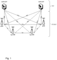
- Figure 1 depicts a 5G System (5GS) architecture comprising 5GC and NG-RAN. It shows how the base stations are connected to each other and the nodes in 5GC.
- the interface between the base stations are referred to as Xn.
- the interface between the base stations and core network nodes such as Access and Mobility Function /User Plane Function (AMF/ UPF) nodes and the core network are referred to as NG.
- AMF/ UPF Access and Mobility Function /User Plane Function
- Figure 2 depicts UE state machine and state transitions between NR/5GC, E-UTRA/EPC and E-UTRA/5GC.
- NR and E-UTRA i.e. LTE connected to 5GC
- RRC_INACTIVE a new RRC state called RRC_INACTIVE has been introduced.
- NG-RAN refers to either NR or LTE connected to 5G Core (5GC) network.
- the UE In RRC_INACTIVE, the UE stores certain configurations, e.g. Data Radio Bearer (DRB) configurations and physical layers parameters. When the UE need to resume the connection, it transmits an RRCConnectionResumeRequest or RRCResumeRequest message in LTE and NR respectively. The UE may then reuse the stored settings and reduce the time and signaling needed to enter RRC_CONNECTED.
- DRB Data Radio Bearer
- NR and LTE may be deployed without any interworking, denoted by NR Stand-Alone (SA) operation, that is gNB in NR may be connected to 5GC ( Option 2 ) and eNB may be connected to EPC ( Option 1 ) with no interconnection between the two.
- SA NR Stand-Alone
- the first supported version of NR is the so-called E-UTRAN-NR Dual Connectivity (EN-DC), ( Option 3 ).
- E-UTRAN-NR Dual Connectivity EN-DC
- a deployment, dual connectivity between NR and LTE is applied with LTE as a master node and NR as a secondary node.
- the RAN node (gNB) supporting NR may not have a control plane connection to EPC, instead it relies on the LTE as Master node (MeNB). This is also referred to as Non-standalone NR.
- MeNB Master node
- Non-standalone NR it should be noted that that in this case the functionality of an NR cell is limited and would be used for connected mode UEs as a booster and/or diversity leg, but an RRC_IDLE UE cannot camp on these NR cells.
- option 2 supports stand-alone NR deployment where gNB is connected to 5GC.
- LTE may also be connected to 5GC using eLTE, E-UTRA/5GC, or LTE/5GC and the node may be referred to as an ng-eNB ( Option 5 ).
- eLTE means that LTE is connected to 5GC.
- both NR and LTE are seen as part of the NG-RAN (and both the ng-eNB and the gNB can be referred to as NG-RAN nodes).
- Option 4 and Option 7 are other variants of dual connectivity between LTE and NR which will be standardized as part of NG-RAN connected to 5GC, denoted by MR-DC (Multi-Radio Dual Connectivity).
- MR-DC Multi-Radio Dual Connectivity
- eNB base station supporting option 3 there may be an eNB base station supporting option 3, 5 and 7 in the same network as an NR base station supporting option 2 and 4.
- CA Carrier Aggregation
- MCG Master Cell Group
- SCG Secondary Cell Group
- NR-NR DC dual connectivity between nodes on same RAT
- the Release-13 solution is based on that the UE sends an RRCConnectionResumeRequest message to the network and in response may receive an RRCConnectionResume message from the network.
- the RRCConnectionResume message is not encrypted but integrity protected.
- the resume procedure in LTE may be found in the 3GPP RRC specifications TS 36.331.
- RRC_IDLE with suspended AS context
- RRC_CONNECTED that triggers a transition from RRC_IDLE to RRC_CONNECTED.
- RRC connection establishment subclause 5.3.3 RRC connection establishment
- the RRC state model is updated in NR and in eLTE, i.e. LTE connected to 5GC, and a new RRC_INACTIVE state is introduced in addition to the existing RRC_IDLE and RRC_CONNECTED states inherited from LTE.
- RRC_INACTIVE the UE context from a previous RRC connection is stored in the RAN and is re-used the next time an RRC connection is established.
- the UE context includes information such as the UE security configuration, configured radio bearers etc.
- a UE state machine and state transitions in NR is depicted in Figure 3 .
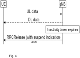
- the NR RRC_INACTIVE mode is realized by introducing two new procedures RRC connection suspend also called RRC connection release with Suspended Configuration ( SuspendConfig ) and "RRC connection resume. See Figure 4 .
- the gNB suspends a connection with UL and DL data transmissions and moves the UE from NR RRC_CONNECTED to NR RRC_INACTIVE by sending an RRCRelease message with suspend indication or configuration to the UE. This may happen for example after the UE has been inactive for a certain period which causes the gNB internal inactivity timer to expire.
- Both the UE and the gNB stores the UE context and the associated identifier, referred to as I-RNTI.
- the UE resumes the connection by sending an RRC resume request including the following information to the gNB which the UE attempts to resume the connection towards. It should be noted that it may be another cell/gNB compared to the cell/gNB where the connection was suspended.
- the source gNB locates the UE context based on the I-RNTI and verifies the request based on the security token, see next section. If successful, the gNB forwards the UE context to the target gNB, which then responds to the UE with RRC resume to confirm the connection is being resumed.
- the RRC resume message may also comprise configurations to reconfigure the radio bearers being resumed.
- the UE acknowledges the reception of the RRC re-establishment by sending RRC re-establishment complete. See Figure 5 .
- the UE may receive a message on SRB1 that should also be encrypted, and integrity protected, as described above:
- RRCReject message with wait timer or RRCSetup message (fallback to RRC_IDLE) but on SRB0, i.e. not encrypted or integrity protected.
- SRB is a Signaling Radio Bearer. All these possible responses are shown as follows in the specifications:
- the NR RRCReconfiguration message is shown below:
- RadioBearerConfig This is the IE that holds the configuration of the radio bearers (DRBs and SRBs).
- a UE may have two radio bearer configurations (radioBearerConfig and radioBearerConfig2).
- RadioBeaerConfig2 is usually used when the UE is in DC, but it can be used even before the UE is standalone mode (i.e. to prepare for a DC).
- the radioBearerConfig and radioBearerConfig2 are mainly distinguished by the security configuration (keys, algorithms) used by the PDCP. Normally, radioBearerConfig holds the configuration of the bearers associated with the master key while radioBearerConfig2 holds the configuration of the bearers associated with the secondary key.
- radioBeaerConfig2 can be associated with the secondary key.
- the structure of the radioBearerConfig is shown below:
- mrdc-SecondaryCellGroup This includes the lower layer configuration for the secondary cell group when DC is configured. For the case of NE-DC, this will include eutra-SCG, while for the case of NR-DC, it will include the NR cell group configuration.
- NR is the secondary cell group and for this case, the IE secondaryCellGroup is used (i.e. the master cell group in this case will be an EUTRA cell group and is provided to the UE via the LTE RRCConnectionReconfiguration message)
- cellGroupID of 0 indicates the master cell
- the network may configure a UE to perform measurements, mainly for mobility reasons.
- the measurement framework in NR is mainly adopted from LTE, but supports additional features such as e.g.:
- the NR measurement configuration comprises the following parameters:
- An RRC_CONNECTED UE maintains a single measurement object list, a single reporting configuration list, and a single measurement identities list.
- the measurement object list possibly includes NR intra-frequency object(s), NR inter-frequency object(s) and inter-RAT objects.
- the reporting configuration list includes NR and inter-RAT reporting configurations. Any measurement object can be linked to any reporting configuration of the same RAT type. Some reporting configurations may not be linked to a measurement object. Likewise, some measurement objects may not be linked to a reporting configuration.
- the measurement procedures distinguish the following types of cells:
- the UE measures and reports on the serving cell(s), listed cells and/or detected cells.
- Measurements in NR may be configured to be reported periodically or based on events. If a UE is configured with a periodic measurement reporting, then it will send available measurement every time the assigned periodicity for that measurement expires. When it comes to event triggered measurement reporting, there are several events defined:
- Event A1 (Serving becomes better than threshold)
- the UE shall:
- Ms is the measurement result of the serving cell, not taking into account any offsets.
- Hys is the hysteresis parameter for this event (i.e. hysteresis as defined within reportConfigNR for this event).
- Thresh is the threshold parameter for this event (i.e. a1-Threshold as defined within reportConfigNR for this event).
- Ms is expressed in dBm in case of RSRP, or in dB in case of RSRQ and RS-SINR.
- Hys is expressed in dB.
- Thresh is expressed in the same unit as Ms.
- Event A2 (Serving becomes worse than threshold)
- the UE shall:
- Ms is the measurement result of the serving cell, not taking into account any offsets.
- Hys is the hysteresis parameter for this event (i.e. hysteresis as defined within reportConfigNR for this event).
- Thresh is the threshold parameter for this event (i.e. a2-Threshold as defined within reportConfigNR for this event).
- Ms is expressed in dBm in case of RSRP, or in dB in case of RSRQ and RS-SINR.
- Hys is expressed in dB.
- Thresh is expressed in the same unit as Ms.
- the UE shall:
- Mn is the measurement result of the neighbouring cell, not taking into account any offsets.
- offsetMO as defined within measObjectNR corresponding to the neighbour cell
- Ocn is the cell specific offset of the neighbour cell (i.e. celllndividualOffset as defined within measObjectNR corresponding to the frequency of the neighbour cell), and set to zero if not configured for the neighbour cell.
- Mp is the measurement result of the SpCell, not taking into account any offsets.
- offsetMO the measurement object specific offset of the SpCell
- Ocp is the cell specific offset of the SpCell (i.e. celllndividualOffset as defined within measObjectNR corresponding to the SpCell), and is set to zero if not configured for the SpCell.
- Hys is the hysteresis parameter for this event (i.e. hysteresis as defined within reportConfigNR for this event).
- Off is the offset parameter for this event (i.e. a3-Offset as defined within reportConfigNR for this event).
- Mn, Mp are expressed in dBm in case of RSRP, or in dB in case of RSRQ and RS-SINR.
- Ocn, Ofp, Ocp, Hys, Off are expressed in dB.
- the UE shall:
- Mn is the measurement result of the neighbouring cell, not taking into account any offsets.
- offsetMO as defined within measObjectNR corresponding to the neighbour cell
- Ocn is the measurement object specific offset of the neighbour cell (i.e. celllndividualOffset as defined within measObjectNR corresponding to the neighbour cell), and set to zero if not configured for the neighbour cell.
- Event A5 (SpCell becomes worse than threshold1 and neighbour becomes better than threshold2)
- Mn is the measurement result of the neighbouring cell, not taking into account any offsets.
- offsetMO as defined within measObjectNR corresponding to the neighbour cell
- Ocn is the cell specific offset of the neighbour cell (i.e. celllndividualOffset as defined within measObjectNR corresponding to the neighbour cell), and set to zero if not configured for the neighbour cell.
- Hys is the hysteresis parameter for this event (i.e. hysteresis as defined within reportConfigNR for this event).
- Thresh1 is the threshold parameter for this event (i.e. a5-Threshold1 as defined within reportConfigNR for this event).
- Thresh2 is the threshold parameter for this event (i.e. a5-Threshold2 as defined within reportConfigNR for this event).
- Mn, Mp are expressed in dBm in case of RSRP, or in dB in case of RSRQ and RS-SINR.
- Thresh1 is expressed in the same unit as Mp.
- Thresh2 is expressed in the same unit as Mn.
- the UE shall:
- Mn is the measurement result of the neighbouring cell, not taking into account any offsets.
- Ocn is the cell specific offset of the neighbour cell (i.e. celllndividualOffset as defined within the associated measObjectNR ), and set to zero if not configured for the neighbour cell.
- Ms is the measurement result of the serving cell, not taking into account any offsets.
- Ocs is the cell specific offset of the serving cell (i.e. celllndividualOffset as defined within the associated measObjectNR ), and is set to zero if not configured for the serving cell.
- Hys is the hysteresis parameter for this event (i.e. hysteresis as defined within reportConfigNR for this event).
- Off is the offset parameter for this event (i.e. a6-Offset as defined within reportConfigNR for this event).
- Mn Ms are expressed in dBm in case of RSRP, or in dB in case of RSRQ and RS-SINR.
- Ocn, Ocs, Hys, Off are expressed in dB.
- the ASN.1 coding for the reportConfigNR information element (IE) that is used to configure event based and periodic reporting configurations is shown below:
- the IE ReportConfigNR specifies criteria for triggering of an NR measurement reporting event. Measurement reporting events are based on cell measurement results, which either may be derived based on SS/PBCH block or CSI-RS. These events are labelled AN with N equal to 1, 2 and so on.
- Event A6 Neighbour becomes amount of offset better than SCell.
- the reportConfigInterRAT IE is used, where event based or report based configurations can be made.
- Event B1 (Inter RAT neighbour becomes better than threshold)
- the UE shall:
- Mn is the measurement result of the inter-RAT neighbour cell, not taking into account any offsets.
- the measurement object specific offset of the frequency of the inter-RAT neighbour cell i.e. eutra-Q-OffsetRange as defined within the measObjectEUTRA corresponding to the frequency of the neighbour inter-RAT cell.
- Ocn is the cell specific offset of the inter-RAT neighbour cell (i.e. cellIndividualOffset as defined within the measObjectEUTRA corresponding to the neighbour inter-RAT cell), and set to zero if not configured for the neighbour cell.
- Hys is the hysteresis parameter for this event (i.e. hysteresis as defined within reportConfigInterRAT for this event).
- Thresh is the threshold parameter for this event (i.e. b1-ThresholdEUTRA as defined within reportConfigInterRAT for this event).
- Thresh is expressed in the same unit as Mn.
- Event B2 (PCell becomes worse than threshold1 and inter RAT neighbour becomes better than threshold2)
- the UE shall:
- Mn is the measurement result of the inter-RAT neighbour cell, not taking into account any offsets.
- the measurement object specific offset of the frequency of the inter-RAT neighbour cell i.e. eutra-Q-OffsetRange as defined within the measObjectEUTRA corresponding to the frequency of the inter-RAT neighbour cell.
- Ocn is the cell specific offset of the inter-RAT neighbour cell (i.e. cellIndividualOffset as defined within the measObjectEUTRA corresponding to the neighbour inter-RAT cell), and set to zero if not configured for the neighbour cell.
- Hys is the hysteresis parameter for this event (i.e. hysteresis as defined within reportConfigInterRAT for this event).
- Thresh2 is the threshold parameter for this event (i.e. b2-Threshold2EUTRA as defined within reportConfigInterRAT for this event).
- Thresh1 is expressed in the same unit as Mp.
- the IE ReportConfigInterRAT specifies criteria for triggering of an inter-RAT measurement reporting event.
- the inter-RAT measurement reporting events for E-UTRA are labelled BN with N equal to 1, 2 and so on.
- An object of embodiments herein is to improve the performance of a user equipment, when it is resumed from a suspended connection, in a communications network using Secondary Cell Group, SCG, configurations.
- the object is achieved by a method performed by a User Equipment, UE, and a method performed by a network node defined by the claims.
- the object is achieved by a User Equipment, UE, and a network node defined by the claims.
- SCG/Scell when used herein means SCG and/or Scell.
- an SCG/SCell resume may be triggered by a UE once a configured condition(s) is/are met.
- SCG/Scell may mean SCG or SCell and is also referred to as SCG herein.
- SCG and SCG/Scell may be used interchangeably.
- Those conditions may be, for example, similar to those defined for event triggered measurement reports.
- MCG/Pcell when used herein means MCG and/or Pcell.
- a MN may also configure the UE with conditions to trigger the resumption of a suspended SCG/SCell configuration. That may be performed e.g. in two different manners:
- the UE may directly trigger it once the configured condition(s) is/are met.
- Those conditions may be, for example, similar to those defined for event triggered measurement reports, e.g. signal thresholds, time to trigger, etc.
- Event-triggered such as conditional resume on a suspended SCG (or SCell) configuration based on measurements will result in a faster resumption of SCG as the UE doesn't need to send measurement reports.
- MR-DC Multi-Radio Dual Connectivity
- DC dual connectivity
- multiple SCG configurations may refer to: a single SN with multiple SCG configurations; or multiple SNs with one or more SCG configurations.
- Embodiments herein relate to wireless communication networks in general.
- Figure 7 is a schematic overview depicting a wireless communications network 100.
- the wireless communications network 100 comprises one or more RANs and one or more CNs.
- the wireless communications network 100 may use a number of different technologies, such as Wi-Fi, Long Term Evolution (LTE), LTE-Advanced, 5G, New Radio (NR), Wideband Code Division Multiple Access (WCDMA), Global System for Mobile communications/enhanced Data rate for GSM Evolution (GSM/EDGE), Worldwide Interoperability for Microwave Access (WiMax), or Ultra Mobile Broadband (UMB), just to mention a few possible implementations.
- LTE Long Term Evolution
- NR New Radio
- WCDMA Wideband Code Division Multiple Access
- GSM/EDGE Global System for Mobile communications/enhanced Data rate for GSM Evolution
- WiMax Worldwide Interoperability for Microwave Access
- UMB Ultra Mobile Broadband
- Embodiments herein relate to recent technology trends that are of particular interest in
- a number of network nodes operate in the wireless communications network 100 such as e.g. a network node 110, and a number of Secondary Nodes (SNs) such as e.g. a first SN 111 and a second SN 112. These nodes provide radio coverage in a number of cells which may also be referred to as a beam or a beam group of beams, such as a cell 10 provided by the network node 110, a cell 11 provided by the first SN 111, and a cell 12 provided by the second SN 112.
- SNs Secondary Nodes
- the network node 110 may e.g. be acting as a Master Node (MN) or an SN when serving a UE 120 in the wireless communications network 100, according to embodiments herein.
- the first SN 111 may e.g. be acting as a source SN
- the second SN 112 may e.g. be acting as a target SN when serving the UE 120 in the wireless communications network 100, according to embodiments herein.
- the network node 110, the first SN 111 and the second SN 112 may each be any of a NG-RAN node, a transmission and reception point e.g. a base station, a radio access network node such as a Wireless Local Area Network (WLAN) access point or an Access Point Station (AP STA), an access controller, a base station, e.g.
- a transmission and reception point e.g. a base station
- a radio access network node such as a Wireless Local Area Network (WLAN) access point or an Access Point Station (AP STA)
- WLAN Wireless Local Area Network
- AP STA Access Point Station
- a base station e.g.
- a radio base station such as a NodeB, an evolved Node B (eNB, eNode B), ng-eNB, a base transceiver station, a radio remote unit, an Access Point Base Station, a base station router, a transmission arrangement of a radio base station, a stand-alone access point or any other network unit capable of communicating with a wireless device within the service area served by the network node 110 depending e.g. on the first radio access technology and terminology used.
- the radio network node 110 may be referred to as a serving radio network node and communicates with a UE 120 with Downlink (DL) transmissions to the UE 120 and Uplink (UL) transmissions from the UE 120.
- DL Downlink
- UL Uplink
- one or more UEs operate, such as e.g. the UE 120.
- the UE 120 may also referred to as a device, an loT device, a mobile station, a non-access point (non-AP) STA, a STA, a user equipment and/or a wireless terminals, communicate via one or more Access Networks (AN), e.g. RAN, to one or more core networks (CN).
- AN Access Networks
- CN core networks
- wireless device is a non-limiting term which means any terminal, wireless communication terminal, user equipment, Machine Type Communication (MTC) device, Device to Device (D2D) terminal, or node e.g. smart phone, laptop, mobile phone, sensor, relay, mobile tablets or even a small base station communicating within a cell.
- MTC Machine Type Communication
- D2D Device to Device
- Methods herein may be performed by the UE 120 and the network node 110.
- a Distributed Node (DN) and functionality e.g. comprised in a cloud 130 as shown in Figure 7 , may be used for performing or partly performing the methods herein.
- Figure 8 shows an example method performed by the UE 120.
- the method may be for handling an SCG configuration in the wireless communications network 100.
- some of the method actions performed by the UE 120 will be described here.
- the method comprises one or more of the following actions, which actions may be taken in any suitable order.
- the UE 120 receives from a network node 110, an SCG configuration and a trigger condition related to the signal quality of a cell associated with the SCG configuration.
- the SCG configuration and trigger condition will be used by the UE 120 for resuming a suspended SCG configuration without the need of an explicit signalling from the network node 110.
- the triggering condition may be referred to as a triggering condition configuration. This action may be performed when the UE 120 is in connected mode and has an active SCG configuration.
- the UE 120 may thus be e.g. configured with conditions to trigger a resumption of a SCG configuration that has been suspended.
- the signal quality referred to herein may comprise any quality of a signal in a cell such as e.g. any one or more of: the signal strength, reference signal received power, Signal-to-Noise-Ratio (SNR), Signal-to-Interference-plus-Noise-Ratio (SINR).
- SNR Signal-to-Noise-Ratio
- SINR Signal-to-Interference-plus-Noise-Ratio
- the trigger condition comprises an event condition. E.g. similar to event A4, a Bx event, or a B1 event or any other triggering condition equivalent to an Ax event.
- the trigger condition may in some embodiments, comprise an event condition that is fulfilled when a neighbour cell becomes better than an absolute threshold.
- the received SCG configuration may comprise an RRC reconfiguration with a Reconfiguration With Synchronization associated with the SCG configuration to be applied associated with the trigger condition to be fulfilled.
- the received SCG configuration may be comprised in an RRC reconfiguration message, e.g. including a Reconfiguration With Synchronization associated with the SCG configuration to be applied associated with the trigger condition to be fulfilled.
- a Reconfiguration With Synchronization when used herein means an RRC Reconfiguration message that includes information that will be used by the UE to get synchronization with the secondary node.
- the received SCG configuration may comprise a UE Access Stratum, AS, context identity and information about one or more potential, SCG configurations e.g. in a list of SCG or SCells, to apply.
- the UE 120 may in some embodiments store the SCG configuration and the trigger condition related to the signal quality of a cell associated with the SCG configuration.
- the UE 120 may then have no active radio link connection to the referred SCG or UE 120 may have removed such as e.g. disconnected from, the referred SCG. This means that the used UE 120 SCG configuration is suspended. The UE 120 may then need to resume the suspended SCG configuration.
- the UE 120 performs signal quality measurements of a cell associated with the SCG configuration. This is to keep track of when the trigger condition for the cell is fulfilled. According to embodiments herein the signal quality measurements are not reported back to the network node 110.
- the UE 120 applies the SCG configuration associated to the cell fulfilling the trigger condition. According to embodiments herein, this is performed by the UE 120 itself, in some embodiments without any assistance or instructions from the network node 110. In some embodiments, instructions such as e.g. which random access preamble will be used when accessing a cell associated to the SCG may be given e.g., together with the SCG configuration and/or trigger condition or separately.
- the suspended SCG configuration has been resumed. This is without the need of an explicit signalling from the network node 110 e.g. without the need to wait for the RRCReconfiguration or RRCResume message that will resume the SCG/SCell.
- Figure 9 shows an example method performed by the network node 110.
- the method may be for handling an SCG configuration in the wireless communications network 100.
- some of the method actions performed by the network node 110 will be described here.
- the method comprises one or more of the following actions, which actions may be taken in any suitable order.
- the network node 110 sends to the UE 120, an SCG configuration and a trigger condition related to the signal quality of a cell associated with the SCG configuration. This may be sent to the UE 120 when it is in connected mode.
- the SCG configuration and trigger condition will be used by the UE 120 for resuming a suspended SCG configuration without the need of an explicit signalling from the network node 110.
- the configuring of the UE (120) further comprises configuring the UE 120 to store the SCG configuration and the trigger condition related to the signal quality of a cell associated with the SCG configuration.
- the trigger condition may comprise an event condition. E.g. similar to event A4, a Bx event, or a B1 event or any other triggering condition equivalent to an Ax event.
- the trigger condition may comprise an event condition that is fulfilled when a neighbour cell becomes better than absolute threshold.
- network node 110 configures the UE (120) to:
- the UE 120 is configured with a configuration similar to event A4 such as that Neighbour cell signal quality becomes better than an absolute threshold or any other triggering condition equivalent to an Ax event as defined in reportConfigNR, but unlike the legacy way of sending a measurement report when the conditions are fulfilled, the UE 120 will perform a conditional resume of an SCG. This may be used to resume an NR SCG, e.g. if the network node 110 is an NR master or an LTE SCG, if the network node 110 is an LTE master, as the A4 event is an intra-RAT event.
- the scgToResumeList refers to the list of SCG configurations that are associated with the same triggering conditions. If different triggering conditions are to be configured for different SCG configurations, several Ax events may be configured. Since the events are associated with measurement objects that are referring to a certain frequency, if the different SCGs configurations are referring to different frequencies, i.e. the PSCells, then several Ax events will be required, even if the same triggering conditions, e.g. ax-Threshold, are to be configured.
- EventTriggerConfig IE
- EventTriggerResumeConfig An example is shown below, where the strikeout signifies the items removed from the EventTriggerConfig.
- the UE 120 is configured with a configuration similar to event B1, i.e. Inter-RAT Neighbour becomes better than absolute threshold, but unlike the legacy way of sending a measurement report when the conditions are fulfilled for an inter-RAT neighbour cell, the UE 120 will perform a conditional resume of an SCG. This may be used to resume an NR SCG, if the network node 110 is an NR master or an LTE SCG, if the network node 110 is an LTE master, as the B1 event is an intra-RAT event.
- the scgToResumeList refers to the list of SCG configurations that are associated with the same triggering conditions. If different triggering conditions are to be configured for different SCG configurations, several Bx events may be configured. Since the events are associated with measurement objects that are referring to a certain frequency, if the different SCGs configurations are referring to different frequencies, i.e. the PSCells, then several Bx events will be required, even if the same triggering conditions, e.g. bx-Threshold, are to be configured.
- EventTriggerResumeConfigInterRAT may be used instead of the EventTriggerConfigInterRAT, as shown below:
- the UE 120 when the conditions of the event Ax or Bx are fulfilled, then the UE 120 will act as if it has received an RRCResume message or RRCReconfiguration message from the network node 110, such as an MN, that triggered the resume and performs the SCG resume procedure.
- an RRCResume message or RRCReconfiguration message from the network node 110, such as an MN, that triggered the resume and performs the SCG resume procedure.
- the configuration provided to the UE 120 may comprise an RRCReconfiguration with a ReconfigurationWithSync associated to the cell group to be added, or equivalent, associated with a triggering condition configuration, which may comprise an Ax event configuration, like A4 event.
- a triggering condition configuration which may comprise an Ax event configuration, like A4 event.
- the UE 120 Upon the reception of that configuration the UE 120 starts to perform associated measurements according to the provided triggering configurations.
- the UE 120 applies the RRCReconfiguration with ReconfigurationWithSync message and performs SCG and/or SCell addition.
- conditional SCG and/or SCell addition configuration is provided while the UE 120 is in RRC_CONNECTED. That is done in an RRCReconfiguration message comprising a list of Conditional configurations comprising per cell, an RRCReconfiguration and a triggering condition, or with a new message e.g. referred to as RRCConditionalReconfiguration.
- RRCConditionalReconfiguration Upon reception, of the message the UE 120 starts to monitor the triggering conditions and when a condition is fulfilled the UE 120 applies the associated RRCReconfiguration that may have been stored, and actions upon such as security establishment, random access, etc.
- the SCG resume conditions configured may be kept when the UE 120 transits from RRC_CONNECTED state to RRC_INACTIVE state.
- the UE 120 may benefit from configured conditions to decide whether an RRC Resume Request message (to PCell) should include any request for a specific SCG/SCell. Therefore, instead of having the choice by the UE 120, of which SCG/SCell to indicate on a resume request, this choice is made according to network configured conditions.
- the UE 120 may initiate e.g. a contention-free random-access procedure towards a target network node e.g. a target SN which may infer it is a resume request since it has a suspended configuration for this UE 120.
- the candidate SN may provide configurations for the UE 120 to perform contention-free random-access which will uniquely identify the UE 120. This configuration may be provided via the network node 110 e.g. an MN.
- random access is not inferred as resume request, instead the UE 120 initiates partial RRC Resume Request e.g. towards PSCell, after random access.
- the target network node such as an SN may inform the network node 110 e.g. the MN about the UE 120 resumption request or random-access procedure.
- the network node 110 e.g. the MN may either reject the UE 120 resumption of the SCG, e.g. in case the network decides upon handover of the UE 120 to another RAT, or acknowledge it.
- the network node 110 e.g. the MN may also release or suspend the source network node such as the SN configuration resumed, if any.
- the UE 120 sends an RRC message, e.g. a new RRC message, towards the network node 110 e.g. the MN indicating that it has resumed a particular SCG configuration.
- the indication may include the SCG-ldentity (ID) and optionally the measurement results that triggered the resumption.
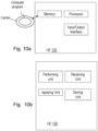
- Figures 10 a and b show an example of the UE 120 comprising a performing unit, a receiving unit, an applying unit and a storing unit see Figure 10b . These may be used to perform the method action 801- 804.
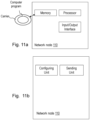
- Figures 11 a and b show an example of the network node 110 comprising a sending unit and a configuring unit see Figure 11b . These may be used to perform the method action 901- 902.
- the UE 120 and the network node 110 may comprise a respective input and output interface configured to communicate with each other, see Figures 10a and 11a .
- the input and output interface may comprise a wireless receiver (not shown) and a wireless transmitter (not shown).
- the embodiments herein may be implemented through a respective processor or one or more processors, such as the processor of a processing circuitry in the UE 120 depicted in Figure 10a and in the network node 110 depicted in Figure 11a , together with computer program code for performing the functions and actions of the embodiments herein.
- the program code mentioned above may also be provided as a computer program product, for instance in the form of a data carrier carrying computer program code for performing the embodiments herein when being loaded into the respective UE 120 and the network node 110.
- One such carrier may be in the form of a CD ROM disc. It is however feasible with other data carriers such as a memory stick.
- the computer program code may furthermore be provided as pure program code on a server and downloaded to the the respective UE 120 and the network node 110.
- the UE 120 and the network node 110 may further comprise a respective memory comprising one or more memory units.
- the respective memory comprises instructions executable by the respective processor in the respective UE 120 and the network node 110.
- a respective computer program comprises instructions, which when executed by the at least one processor, cause the at least one processor of the respective UE 120 and the network node 110 to perform the respective actions above.
- a respective carrier comprises the respective computer program, wherein the carrier is one of an electronic signal, an optical signal, an electromagnetic signal, a magnetic signal, an electric signal, a radio signal, a microwave signal, or a computer-readable storage medium.
- a communication system includes a telecommunication network 3210, such as a 3GPP-type cellular network, which comprises an access network 3211, such as a radio access network, and a core network 3214.
- the access network 3211 comprises a plurality of base stations 3212a, 3212b, 3212c, such as the network node 110, AP STAs NBs, eNBs, gNBs or other types of wireless access points, each defining a corresponding coverage area 3213a, 3213b, 3213c.
- Each base station 3212a, 3212b, 3212c is connectable to the core network 3214 over a wired or wireless connection 3215.
- a first user equipment (UE) such as the UE 120, a Non-AP STA 3291 located in coverage area 3213c is configured to wirelessly connect to, or be paged by, the corresponding base station 3212c.
- a second UE 3292 such as a Non-AP STA in coverage area 3213a is wirelessly connectable to the corresponding base station 3212a. While a plurality of UEs 3291, 3292 are illustrated in this example, the disclosed embodiments are equally applicable to a situation where a sole UE is in the coverage area or where a sole UE is connecting to the corresponding base station 3212.
- the telecommunication network 3210 is itself connected to a host computer 3230, which may be embodied in the hardware and/or software of a standalone server, a cloud-implemented server, a distributed server or as processing resources in a server farm.
- the host computer 3230 may be under the ownership or control of a service provider, or may be operated by the service provider or on behalf of the service provider.
- the connections 3221, 3222 between the telecommunication network 3210 and the host computer 3230 may extend directly from the core network 3214 to the host computer 3230 or may go via an optional intermediate network 3220.
- the intermediate network 3220 may be one of, or a combination of more than one of, a public, private or hosted network; the intermediate network 3220, if any, may be a backbone network or the Internet; in particular, the intermediate network 3220 may comprise two or more sub-networks (not shown).
- the communication system of Figure 12 as a whole enables connectivity between one of the connected UEs 3291, 3292 and the host computer 3230.
- the connectivity may be described as an over-the-top (OTT) connection 3250.
- the host computer 3230 and the connected UEs 3291, 3292 are configured to communicate data and/or signaling via the OTT connection 3250, using the access network 3211, the core network 3214, any intermediate network 3220 and possible further infrastructure (not shown) as intermediaries.
- the OTT connection 3250 may be transparent in the sense that the participating communication devices through which the OTT connection 3250 passes are unaware of routing of uplink and downlink communications.
- a base station 3212 may not or need not be informed about the past routing of an incoming downlink communication with data originating from a host computer 3230 to be forwarded (e.g., handed over) to a connected UE 3291. Similarly, the base station 3212 need not be aware of the future routing of an outgoing uplink communication originating from the UE 3291 towards the host computer 3230.
- a host computer 3310 comprises hardware 3315 including a communication interface 3316 configured to set up and maintain a wired or wireless connection with an interface of a different communication device of the communication system 3300.
- the host computer 3310 further comprises processing circuitry 3318, which may have storage and/or processing capabilities.
- the processing circuitry 3318 may comprise one or more programmable processors, application-specific integrated circuits, field programmable gate arrays or combinations of these (not shown) adapted to execute instructions.
- the host computer 3310 further comprises software 3311, which is stored in or accessible by the host computer 3310 and executable by the processing circuitry 3318.
- the software 3311 includes a host application 3312.
- the host application 3312 may be operable to provide a service to a remote user, such as a UE 3330 connecting via an OTT connection 3350 terminating at the UE 3330 and the host computer 3310. In providing the service to the remote user, the host application 3312 may provide user data which is transmitted using the OTT connection 3350.
- the communication system 3300 further includes a base station 3320 provided in a telecommunication system and comprising hardware 3325 enabling it to communicate with the host computer 3310 and with the UE 3330.
- the hardware 3325 may include a communication interface 3326 for setting up and maintaining a wired or wireless connection with an interface of a different communication device of the communication system 3300, as well as a radio interface 3327 for setting up and maintaining at least a wireless connection 3370 with a UE 3330 located in a coverage area (not shown in Figure 13 ) served by the base station 3320.
- the communication interface 3326 may be configured to facilitate a connection 3360 to the host computer 3310.
- the communication system 3300 further includes the UE 3330 already referred to.
- Its hardware 3335 may include a radio interface 3337 configured to set up and maintain a wireless connection 3370 with a base station serving a coverage area in which the UE 3330 is currently located.
- the hardware 3335 of the UE 3330 further includes processing circuitry 3338, which may comprise one or more programmable processors, application-specific integrated circuits, field programmable gate arrays or combinations of these (not shown) adapted to execute instructions.
- the UE 3330 further comprises software 3331, which is stored in or accessible by the UE 3330 and executable by the processing circuitry 3338.
- the software 3331 includes a client application 3332.
- the host computer 3310, base station 3320 and UE 3330 illustrated in Figure 13 may be identical to the host computer 3230, one of the base stations 3212a, 3212b, 3212c and one of the UEs 3291, 3292 of Figure 12 , respectively.
- the inner workings of these entities may be as shown in Figure 13 and independently, the surrounding network topology may be that of Figure 12 .
- the OTT connection 3350 has been drawn abstractly to illustrate the communication between the host computer 3310 and the use equipment 3330 via the base station 3320, without explicit reference to any intermediary devices and the precise routing of messages via these devices.
- Network infrastructure may determine the routing, which it may be configured to hide from the UE 3330 or from the service provider operating the host computer 3310, or both. While the OTT connection 3350 is active, the network infrastructure may further take decisions by which it dynamically changes the routing (e.g., on the basis of load balancing consideration or reconfiguration of the network).
- the wireless connection 3370 between the UE 3330 and the base station 3320 is in accordance with the teachings of the embodiments described throughout this disclosure.
- One or more of the various embodiments improve the performance of OTT services provided to the UE 3330 using the OTT connection 3350, in which the wireless connection 3370 forms the last segment. More precisely, the teachings of these embodiments may improve the data rate, latency, power consumption and thereby provide benefits such as reduced user waiting time, relaxed restriction on file size, better responsiveness, extended battery lifetime.
- a measurement procedure may be provided for the purpose of monitoring data rate, latency and other factors on which the one or more embodiments improve.
- the measurement procedure and/or the network functionality for reconfiguring the OTT connection 3350 may be implemented in the software 3311 of the host computer 3310 or in the software 3331 of the UE 3330, or both.
- sensors (not shown) may be deployed in or in association with communication devices through which the OTT connection 3350 passes; the sensors may participate in the measurement procedure by supplying values of the monitored quantities exemplified above, or supplying values of other physical quantities from which software 3311, 3331 may compute or estimate the monitored quantities.
- the reconfiguring of the OTT connection 3350 may include message format, retransmission settings, preferred routing etc.; the reconfiguring need not affect the base station 3320, and it may be unknown or imperceptible to the base station 3320. Such procedures and functionalities may be known and practiced in the art.
- measurements may involve proprietary UE signaling facilitating the host computer's 3310 measurements of throughput, propagation times, latency and the like.
- the measurements may be implemented in that the software 3311, 3331 causes messages to be transmitted, in particular empty or 'dummy' messages, using the OTT connection 3350 while it monitors propagation times, errors etc.
- FIG 14 is a flowchart illustrating a method implemented in a communication system, in accordance with one embodiment not covered by the present set of claims.
- the communication system includes a host computer, a base station such as an AP STA, and a UE such as a Non-AP STA which may be those described with reference to Figure 12 and Figure 13 .
- a host computer provides user data.
- the host computer provides the user data by executing a host application.
- the host computer initiates a transmission carrying the user data to the UE.
- the base station transmits to the UE the user data which was carried in the transmission that the host computer initiated, in accordance with the teachings of the embodiments described throughout this disclosure.
- the UE executes a client application associated with the host application executed by the host computer.
- FIG. 15 is a flowchart illustrating a method implemented in a communication system, in accordance with one embodiment not covered by the present set of claims.
- the communication system includes a host computer, a base station such as an AP STA, and a UE such as a Non-AP STA which may be those described with reference to Figure 12 and Figure 13 .
- the host computer provides user data.
- the host computer provides the user data by executing a host application.
- the host computer initiates a transmission carrying the user data to the UE. The transmission may pass via the base station, in accordance with the teachings of the embodiments described throughout this disclosure.
- the UE receives the user data carried in the transmission.
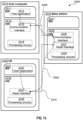
- FIG 16 is a flowchart illustrating a method implemented in a communication system, in accordance with one embodiment not covered by the present set of claims.
- the communication system includes a host computer, a base station such as an AP STA, and a UE such as a Non-AP STA which may be those described with reference to Figure 12 and Figure 13 .
- a host computer e.g., a host computer
- a base station e.g., a base station
- UE such as a Non-AP STA which may be those described with reference to Figure 12 and Figure 13 .
- the UE receives input data provided by the host computer.
- the UE provides user data.
- the UE provides the user data by executing a client application.
- the UE executes a client application which provides the user data in reaction to the received input data provided by the host computer.
- the executed client application may further consider user input received from the user.
- the UE initiates, in an optional third substep 3630, transmission of the user data to the host computer.
- the host computer receives the user data transmitted from the UE, in accordance with the teachings of the embodiments described throughout this disclosure.
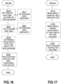
- FIG 17 is a flowchart illustrating a method implemented in a communication system, in accordance with one embodiment not covered by the present set of claims.
- the communication system includes a host computer, a base station such as an AP STA, and a UE such as a Non-AP STA which may be those described with reference to Figure 12 and Figure 13 .
- a base station such as an AP STA
- a UE such as a Non-AP STA which may be those described with reference to Figure 12 and Figure 13 .
- the base station receives user data from the UE.
- the base station initiates transmission of the received user data to the host computer.
- the host computer receives the user data carried in the transmission initiated by the base station.
- Abbreviation Explanation CA Carrier Aggregation DC Dual Connectivity EN-DC E-UTRA NR Dual Connectivity eNB LTE Base Station (evolved Node B) gNB NR Base Station LTE Long Term Evolution MCG Master Cell Group MN Master Node MR-DC Multi-Radio Dual Connectivity NR New Radio PCell Primary Cell PSCell Primary Cell of the SCG RAT Radio Access Technology RRC Radio Resource Control SCG Secondary Cell Group SCell Secondary Cell SN Secondary Node UE User Equipment
Landscapes
- Engineering & Computer Science (AREA)
- Computer Networks & Wireless Communication (AREA)
- Signal Processing (AREA)
- Mobile Radio Communication Systems (AREA)
Claims (22)
- Verfahren, das durch ein Benutzergerät, UE, (120) durchgeführt wird, zum Handhaben einer Sekundärzellengruppenkonfiguration, SCG-Konfiguration, in einem drahtlosen Kommunikationsnetz (100), wobei das Verfahren durch Folgendes gekennzeichnet ist:Empfangen (801) von einem Netzknoten (110), während sich das UE (120) im RRC_CONNECTED-Zustand befindet, einer RRC-Rekonfigurationsnachricht, die eine Liste konditionaler SCG-Konfigurationen beinhaltet, die Auslösebedingungen umfassen, die auf Signalqualitätsmessungen basieren, um Anwendung einer SCG-Konfiguration auszulösen,nach Empfang der RRC-Rekonfigurationsnachricht, während sich das UE (120) im RRC_CONNECTED-Zustand befindet, Einleiten von Überwachung der Auslösebedingungen von Zellen, die mit den SCG-Konfigurationen assoziiert sind,wenn die Auslösebedingung für eine Zelle gemäß den empfangenen konditionalen SCG-Konfigurationen erfüllt wird, Anwenden (804) der assoziierten SCG-Konfiguration auf die Zelle, die die Auslösebedingung erfüllt.
- Verfahren nach Anspruch 1, ferner umfassend:
Speichern (802) der SCG-Konfiguration und der Auslösebedingung in Bezug auf die Signalqualität einer Zelle, die mit der SCG-Konfiguration assoziiert ist. - Verfahren nach einem der Ansprüche 1-2, wobei die Auslösebedingung eine Ereignisbedingung umfasst.
- Verfahren nach einem der Ansprüche 1-2, wobei die Auslösebedingung eine Ereignisbedingung umfasst, die erfüllt wird, wenn eine Zelle, die mit einer SCG-Konfiguration assoziiert ist, die in der Liste konditionaler SCG-Konfigurationen umfasst ist, besser als ein absoluter Schwellenwert wird.
- Verfahren nach einem der Ansprüche 1-4, wobei die empfangene SCG-Konfiguration eine Funkressourcensteuerungsrekonfiguration, RRC-Rekonfiguration, mit einer Rekonfiguration mit Synchronisation umfasst, die mit der anzuwendenden SCG-Konfiguration assoziiert ist, die mit der zu erfüllenden Auslösebedingung assoziiert ist.
- Verfahren nach einem der Ansprüche 1-4, wobei die empfangene SCG-Konfiguration eine UE-Zugriffsschichtkontextidentität, UE-AS-Kontextidentität, und Informationen über eine oder mehrere potenzielle anzuwendende SCG umfasst.
- Verfahren, das durch einen Netzknoten (110) durchgeführt wird, zum Handhaben einer Sekundärzellengruppenkonfiguration, SCG-Konfiguration, in einem drahtlosen Kommunikationsnetz (100), wobei das Verfahren durch Folgendes gekennzeichnet ist:Senden (901) an ein Benutzergerät, UE, (120) im RRC_CONNECTED-Zustand einer RRC-Rekonfigurationsnachricht, die eine Liste konditionaler SCG-Konfigurationen beinhaltet, die Auslösebedingungen umfassen, die auf Signalqualitätsmessungen basieren, um Anwendung einer SCG-Konfiguration auszulösen, undKonfigurieren (902) des UE (120) zu Folgendem:- Einleiten von Überwachung der Auslösebedingungen von Zellen, die mit den SCG-Konfigurationen assoziiert sind, nach Empfang der RRC-Rekonfigurationsnachricht, während sich das UE (120) im RRC_CONNECTED-Zustand befindet, und- wenn die Auslösebedingung für eine Zelle gemäß den empfangenen konditionalen SCG-Konfigurationen erfüllt wird, Anwenden der assoziierten SCG-Konfiguration auf die Zelle, die die Auslösebedingung erfüllt.
- Verfahren nach Anspruch 7, wobei das Konfigurieren (902) des UE (120) ferner Konfigurieren des UE (120) zu Folgendem umfasst:- Speichern der SCG-Konfiguration und der Auslösebedingung in Bezug auf die Signalqualität einer Zelle, die mit der SCG-Konfiguration assoziiert ist.
- Verfahren nach einem der Ansprüche 7-8, wobei die Auslösebedingung eine Ereignisbedingung umfasst.
- Verfahren nach einem der Ansprüche 7-9, wobei die Auslösebedingung eine Ereignisbedingung umfasst, die erfüllt wird, wenn eine Zelle, die mit einer SCG-Konfiguration assoziiert ist, die in der Liste konditionaler SCG-Konfigurationen umfasst ist, besser als ein absoluter Schwellenwert wird.
- Verfahren nach einem der Ansprüche 7-10, wobei die gesendete SCG-Konfiguration eine Funkressourcensteuerungsrekonfiguration, RRC-Rekonfiguration, mit einer Rekonfiguration mit Synchronisation umfasst, die mit der anzuwendenden SCG-Konfiguration assoziiert ist, die mit der zu erfüllenden Auslösebedingung assoziiert ist.
- Benutzergerät, UE, (120), das dazu konfiguriert ist, eine Sekundärzellengruppenkonfiguration, SCG-Konfiguration, in einem drahtlosen Kommunikationsnetz (100) zu handhaben, wobei das UE (120) dadurch gekennzeichnet ist, dass es zu Folgendem konfiguriert ist:Empfangen von einem Netzknoten (110), während sich das UE (120) im RRC_CONNECTED-Zustand befindet, einer RRC-Rekonfigurationsnachricht, die eine Liste konditionaler SCG-Konfigurationen beinhaltet, die Auslösebedingen umfassen, die auf Signalqualitätsmessungen basieren, um Anwendung einer SCG-Konfiguration auszulösen,nach Empfang der RRC-Rekonfigurationsnachricht, während sich das UE (120) im RRC_CONNECTED-Zustand befindet, Einleiten von Überwachung der Auslösebedingungen von Zellen, die mit den SCG-Konfigurationen assoziiert sind, undwenn die Auslösebedingung für eine Zelle gemäß den empfangenen konditionalen SCG-Konfigurationen erfüllt wird, Anwenden der assoziierten SCG-Konfiguration auf die Zelle, die die Auslösebedingung erfüllt.
- UE (120) nach Anspruch 12, das ferner zu Folgendem konfiguriert ist:
Speichern der SCG-Konfiguration und der Auslösebedingung in Bezug auf die Signalqualität einer Zelle, die mit der SCG-Konfiguration assoziiert ist. - UE (120) nach einem der Ansprüche 12-13, wobei die Auslösebedingung dazu angepasst ist, eine Ereignisbedingung zu umfassen.
- UE (120) nach einem der Ansprüche 12-14, wobei die Auslösebedingung dazu angepasst ist, eine Ereignisbedingung zu umfassen, die erfüllt wird, wenn eine Zelle, die mit einer SCG-Konfiguration assoziiert ist, die in der Liste konditionaler SCG-Konfigurationen umfasst ist, besser als ein absoluter Schwellenwert wird.
- UE nach einem der Ansprüche 12-15, wobei die empfangene SCG-Konfiguration dazu angepasst ist, eine Funkressourcensteuerungsrekonfiguration, RRC-Rekonfiguration, mit einer Rekonfiguration mit Synchronisation zu umfassen, die mit der anzuwendenden SCG-Konfiguration assoziiert ist, die mit der zu erfüllenden Auslösebedingung assoziiert ist.
- UE nach einem der Ansprüche 12-15, wobei die empfangene SCG-Konfiguration eine UE-Zugriffsschichtkontextidentität, UE-AS-Kontextidentität, und Informationen über eine oder mehrere potenzielle SCG-Konfigurationen umfasst.
- Netzknoten (110), der dazu konfiguriert ist, eine Sekundärzellengruppenkonfiguration, SCG-Konfiguration, in einem drahtlosen Netz (100) zu handhaben, wobei der Netzknoten dadurch gekennzeichnet ist, dass er zu Folgendem konfiguriert ist:Senden an ein Benutzergerät, UE, (120) im RRC_CONNECTED-Zustand einer RRC-Rekonfigurationsnachricht, die eine Liste konditionaler SCG-Konfigurationen beinhaltet, die Auslösebedingungen umfassen, die auf Signalqualitätsmessungen basieren, um Anwendung einer SCG-Konfiguration auszulösen,Konfigurieren des UE (120) zu Folgendem:- Einleiten von Überwachung der Auslösebedingungen von Zellen, die mit den SCG-Konfigurationen assoziiert sind, nach Empfang der RRC-Rekonfigurationsnachricht, während sich das UE (120) im RRC_CONNECTED-Zustand befindet, und- wenn die Auslösebedingung für eine Zelle gemäß den empfangenen konditionalen SCG-Konfigurationen erfüllt wird, Anwenden der assoziierten SCG-Konfiguration auf die Zelle, die die Auslösebedingung erfüllt.
- Netzknoten (110) nach Anspruch 18, der ferner dazu konfiguriert ist, das UE (120) zu Folgendem zu konfigurieren:- Speichern der SCG-Konfiguration und der Auslösebedingung in Bezug auf die Signalqualität einer Zelle, die mit der SCG-Konfiguration assoziiert ist.
- Netzknoten (110) nach einem der Ansprüche 18-19, wobei die Auslösebedingung dazu konfiguriert ist, eine Ereignisbedingung zu umfassen.
- Netzknoten (110) nach einem der Ansprüche 18-20, wobei die Auslösebedingung dazu angepasst ist, eine Ereignisbedingung zu umfassen, die erfüllt wird, wenn eine Zelle, die mit einer SCG-Konfiguration assoziiert ist, die in der Liste konditionaler SCG-Konfigurationen umfasst ist, besser als ein absoluter Schwellenwert wird.
- Netzknoten (110) nach einem der Ansprüche 18-21, wobei die gesendete SCG-Konfiguration dazu konfiguriert ist, eine Funkressourcensteuerungsrekonfiguration, RRC-Rekonfiguration, mit einer Rekonfiguration mit Synchronisation zu umfassen, die mit der anzuwendenden SCG-Konfiguration assoziiert ist, die mit der zu erfüllenden Auslösebedingung assoziiert ist.
Applications Claiming Priority (2)
| Application Number | Priority Date | Filing Date | Title |
|---|---|---|---|
| US201962820872P | 2019-03-20 | 2019-03-20 | |
| PCT/SE2020/050004 WO2020190188A1 (en) | 2019-03-20 | 2020-01-08 | Handling a secondary cell group configuration |
Publications (3)
| Publication Number | Publication Date |
|---|---|
| EP3942897A1 EP3942897A1 (de) | 2022-01-26 |
| EP3942897B1 true EP3942897B1 (de) | 2024-12-18 |
| EP3942897C0 EP3942897C0 (de) | 2024-12-18 |
Family
ID=69185670
Family Applications (1)
| Application Number | Title | Priority Date | Filing Date |
|---|---|---|---|
| EP20701523.1A Active EP3942897B1 (de) | 2019-03-20 | 2020-01-08 | Handhabung einer sekundärzellengruppenkonfiguration |
Country Status (7)
| Country | Link |
|---|---|
| US (2) | US12035393B2 (de) |
| EP (1) | EP3942897B1 (de) |
| JP (1) | JP7275304B2 (de) |
| CN (1) | CN113647194B (de) |
| BR (1) | BR112021018488A2 (de) |
| SG (1) | SG11202109808QA (de) |
| WO (1) | WO2020190188A1 (de) |
Families Citing this family (12)
| Publication number | Priority date | Publication date | Assignee | Title |
|---|---|---|---|---|
| BR112021018488A2 (pt) * | 2019-03-20 | 2021-11-23 | Ericsson Telefon Ab L M | Métodos realizados por um equipamento de usuário e por um nó de rede para manipular uma configuração de grupo de células secundárias em uma rede de comunicações sem fio, programa de computador, portadora, equipamento de usuário, e, nó de rede |
| USD981052S1 (en) | 2020-10-15 | 2023-03-14 | Towerstar Pets, Llc | Feeding mat |
| USD981053S1 (en) | 2020-10-15 | 2023-03-14 | Towerstar Pets, Llc | Feeding mat |
| CN116368941A (zh) | 2020-10-22 | 2023-06-30 | 三星电子株式会社 | 多rat双连接网络中控制辅小区组的方法和设备 |
| IN202041046102A (de) * | 2020-10-22 | 2022-04-29 | ||
| WO2022086279A1 (en) * | 2020-10-22 | 2022-04-28 | Samsung Electronics Co., Ltd. | Method and apparatus for controlling secondary cell group in a multi-rat dual connectivity network |
| CN115150864A (zh) * | 2021-03-31 | 2022-10-04 | 北京三星通信技术研究有限公司 | 通信方法、装置、电子设备及计算机可读存储介质 |
| WO2022205078A1 (en) | 2021-03-31 | 2022-10-06 | Apple Inc. | Uplink timing synchronization maintenance in secondary cell group |
| JP7481299B2 (ja) * | 2021-06-29 | 2024-05-10 | 株式会社デンソー | 通信装置、マスタノード、及び通信制御方法 |
| CN117356138A (zh) * | 2021-08-03 | 2024-01-05 | Oppo广东移动通信有限公司 | 信息获取方法、信息提供方法、装置、设备及存储介质 |
| CN118695306A (zh) * | 2023-03-22 | 2024-09-24 | 夏普株式会社 | 小区变更执行方法以及用户设备 |
| WO2024214173A1 (ja) | 2023-04-11 | 2024-10-17 | 京セラ株式会社 | ユーザ装置、ノード、及び通信方法 |
Family Cites Families (17)
| Publication number | Priority date | Publication date | Assignee | Title |
|---|---|---|---|---|
| KR20210123428A (ko) * | 2014-01-17 | 2021-10-13 | 삼성전자주식회사 | 이중 연결에서의 특별한 Scell 선택의 처리를 위한 방법 및 시스템 |
| US9713044B2 (en) * | 2014-01-30 | 2017-07-18 | Sharp Kabushiki Kaisha | Systems and methods for dual-connectivity operation |
| KR102174133B1 (ko) * | 2014-03-21 | 2020-11-04 | 삼성전자 주식회사 | 이동 통신 시스템에서 셀 측정 수행 및 스몰 셀의 특수 기능 셀을 선택하는 방법 및 장치 |
| GB2528913B (en) * | 2014-08-04 | 2017-03-01 | Samsung Electronics Co Ltd | Signalling in dual connectivity mobile communication networks |
| US9820332B2 (en) * | 2014-08-07 | 2017-11-14 | Lg Electronics Inc. | Method for deactivating SCells during SCG change procedure and a device therefor |
| KR102249314B1 (ko) | 2014-09-26 | 2021-05-06 | 선 페이턴트 트러스트 | 디바이스 투 디바이스(d2d) 통신에 대한 개선된 자원 할당 |
| US10728944B2 (en) * | 2014-09-29 | 2020-07-28 | Telefonaktiebolaget Lm Ericsson (Publ) | Indication to the master e-node B of successful primary secondary cell activation in dual connectivity |
| CN110771254B (zh) | 2017-06-15 | 2022-09-16 | 高通股份有限公司 | 用于多连接性模式中的用户设备移动性的技术和装置 |
| WO2019031827A1 (en) | 2017-08-07 | 2019-02-14 | Lg Electronics Inc. | METHOD AND APPARATUS FOR MAINTAINING DC CONFIGURATION |
| US11483891B2 (en) * | 2017-08-11 | 2022-10-25 | Samsung Electronics Co., Ltd. | Method for performing bearer type change of a plurality of bearers configured for user equipment |
| KR102263160B1 (ko) * | 2017-09-29 | 2021-06-10 | 삼성전자주식회사 | 무선 통신 시스템의 듀얼 커넥티비티에서 사용자 평면을 처리하는 방법 및 사용자 장비 |
| US10939366B2 (en) | 2019-02-13 | 2021-03-02 | Telefonaktiebolaget Lm Ericsson (Publ) | User equipment and method in a wireless communications network |
| KR20200098921A (ko) * | 2019-02-13 | 2020-08-21 | 삼성전자주식회사 | 차세대 이동통신 시스템에서 단말이 보조 셀그룹의 설정을 포함한 rrc 재설정 메시지를 수신했을 때의 동작 방법 및 장치 |
| BR112021018488A2 (pt) * | 2019-03-20 | 2021-11-23 | Ericsson Telefon Ab L M | Métodos realizados por um equipamento de usuário e por um nó de rede para manipular uma configuração de grupo de células secundárias em uma rede de comunicações sem fio, programa de computador, portadora, equipamento de usuário, e, nó de rede |
| WO2021015659A1 (en) * | 2019-07-19 | 2021-01-28 | Telefonaktiebolaget Lm Ericsson (Publ) | Conditional configuration in a wireless communication network |
| WO2021201758A1 (en) * | 2020-03-30 | 2021-10-07 | Telefonaktiebolaget Lm Ericsson (Publ) | Conditional configuration in a wireless communication network |
| CN116326174A (zh) * | 2020-08-06 | 2023-06-23 | 瑞典爱立信有限公司 | 用于主节点发起的条件主辅助小区添加的系统和方法 |
-
2020
- 2020-01-08 BR BR112021018488A patent/BR112021018488A2/pt unknown
- 2020-01-08 SG SG11202109808Q patent/SG11202109808QA/en unknown
- 2020-01-08 US US17/439,943 patent/US12035393B2/en active Active
- 2020-01-08 JP JP2021555593A patent/JP7275304B2/ja active Active
- 2020-01-08 EP EP20701523.1A patent/EP3942897B1/de active Active
- 2020-01-08 WO PCT/SE2020/050004 patent/WO2020190188A1/en not_active Ceased
- 2020-01-08 CN CN202080022401.0A patent/CN113647194B/zh active Active
-
2024
- 2024-06-12 US US18/741,392 patent/US20240414795A1/en active Pending
Also Published As
| Publication number | Publication date |
|---|---|
| US20240414795A1 (en) | 2024-12-12 |
| CN113647194B (zh) | 2024-04-30 |
| US12035393B2 (en) | 2024-07-09 |
| CN113647194A (zh) | 2021-11-12 |
| EP3942897C0 (de) | 2024-12-18 |
| WO2020190188A1 (en) | 2020-09-24 |
| EP3942897A1 (de) | 2022-01-26 |
| BR112021018488A2 (pt) | 2021-11-23 |
| US20220183094A1 (en) | 2022-06-09 |
| SG11202109808QA (en) | 2021-10-28 |
| JP7275304B2 (ja) | 2023-05-17 |
| JP2022525766A (ja) | 2022-05-19 |
Similar Documents
| Publication | Publication Date | Title |
|---|---|---|
| EP3942897B1 (de) | Handhabung einer sekundärzellengruppenkonfiguration | |
| EP3949678B1 (de) | Benutzergerät, funknetzwerkknoten, computerprogramm produkte, träger und darin ausgeführte verfahren zur kommunikationshandhabung | |
| US12127027B2 (en) | Early measurement reporting with RRC resume request message and indication of request for early measurements in association with paging | |
| US10939366B2 (en) | User equipment and method in a wireless communications network | |
| US12328781B2 (en) | Master node, a secondary node, a user equipment and methods therein for handling of a secondary cell group (SCG) | |
| US20240406778A1 (en) | Early Measurement Reporting with RRC Resume Complete Like Message | |
| US11937113B2 (en) | Flexible early measurement reporting | |
| US11284468B2 (en) | Suspending/resuming measurements in RRC inactive state | |
| CN106717086B (zh) | 无线电站、无线电终端、及其方法 | |
| US11985525B2 (en) | Early measurement configuration handling in 2-steps resume request-release | |
| WO2021080481A1 (en) | User equipment, first network node, second network node and methods for handling a conditional handover in a wireless communications network | |
| EP3964023A1 (de) | Benutzerausrüstung, netzwerkknoten und verfahren in einem drahtloskommunikationsnetzwerk | |
| EP3834447B1 (de) | Benutzergerät und verfahren in einem drahtlosen kommunikationsnetz | |
| US20220132607A1 (en) | Role switch handling in a multi connectivity configuration | |
| US20250081280A1 (en) | Managing measurement in small data transmission | |
| CN118743304A (zh) | 管理在小数据发送中的测量 |
Legal Events
| Date | Code | Title | Description |
|---|---|---|---|
| STAA | Information on the status of an ep patent application or granted ep patent |
Free format text: STATUS: UNKNOWN |
|
| STAA | Information on the status of an ep patent application or granted ep patent |
Free format text: STATUS: THE INTERNATIONAL PUBLICATION HAS BEEN MADE |
|
| PUAI | Public reference made under article 153(3) epc to a published international application that has entered the european phase |
Free format text: ORIGINAL CODE: 0009012 |
|
| STAA | Information on the status of an ep patent application or granted ep patent |
Free format text: STATUS: REQUEST FOR EXAMINATION WAS MADE |
|
| 17P | Request for examination filed |
Effective date: 20211012 |
|
| AK | Designated contracting states |
Kind code of ref document: A1 Designated state(s): AL AT BE BG CH CY CZ DE DK EE ES FI FR GB GR HR HU IE IS IT LI LT LU LV MC MK MT NL NO PL PT RO RS SE SI SK SM TR |
|
| STAA | Information on the status of an ep patent application or granted ep patent |
Free format text: STATUS: EXAMINATION IS IN PROGRESS |
|
| 17Q | First examination report despatched |
Effective date: 20220429 |
|
| DAV | Request for validation of the european patent (deleted) | ||
| DAX | Request for extension of the european patent (deleted) | ||
| GRAP | Despatch of communication of intention to grant a patent |
Free format text: ORIGINAL CODE: EPIDOSNIGR1 |
|
| STAA | Information on the status of an ep patent application or granted ep patent |
Free format text: STATUS: GRANT OF PATENT IS INTENDED |
|
| INTG | Intention to grant announced |
Effective date: 20240404 |
|
| GRAJ | Information related to disapproval of communication of intention to grant by the applicant or resumption of examination proceedings by the epo deleted |
Free format text: ORIGINAL CODE: EPIDOSDIGR1 |
|
| STAA | Information on the status of an ep patent application or granted ep patent |
Free format text: STATUS: EXAMINATION IS IN PROGRESS |
|
| INTC | Intention to grant announced (deleted) | ||
| RIN1 | Information on inventor provided before grant (corrected) |
Inventor name: TEYEB, OUMER Inventor name: RUGELAND, PATRIK Inventor name: ARAUJO, LIAN Inventor name: DA SILVA, ICARO L. J. Inventor name: YILMAZ, OSMAN NURI CAN |
|
| GRAP | Despatch of communication of intention to grant a patent |
Free format text: ORIGINAL CODE: EPIDOSNIGR1 |
|
| STAA | Information on the status of an ep patent application or granted ep patent |
Free format text: STATUS: GRANT OF PATENT IS INTENDED |
|
| INTG | Intention to grant announced |
Effective date: 20240906 |
|
| GRAS | Grant fee paid |
Free format text: ORIGINAL CODE: EPIDOSNIGR3 |
|
| GRAA | (expected) grant |
Free format text: ORIGINAL CODE: 0009210 |
|
| STAA | Information on the status of an ep patent application or granted ep patent |
Free format text: STATUS: THE PATENT HAS BEEN GRANTED |
|
| AK | Designated contracting states |
Kind code of ref document: B1 Designated state(s): AL AT BE BG CH CY CZ DE DK EE ES FI FR GB GR HR HU IE IS IT LI LT LU LV MC MK MT NL NO PL PT RO RS SE SI SK SM TR |
|
| REG | Reference to a national code |
Ref country code: CH Ref legal event code: EP |
|
| REG | Reference to a national code |
Ref country code: DE Ref legal event code: R096 Ref document number: 602020043295 Country of ref document: DE |
|
| REG | Reference to a national code |
Ref country code: IE Ref legal event code: FG4D |
|
| U01 | Request for unitary effect filed |
Effective date: 20241218 |
|
| U07 | Unitary effect registered |
Designated state(s): AT BE BG DE DK EE FI FR IT LT LU LV MT NL PT RO SE SI Effective date: 20250102 |
|
| U20 | Renewal fee for the european patent with unitary effect paid |
Year of fee payment: 6 Effective date: 20250127 |
|
| PG25 | Lapsed in a contracting state [announced via postgrant information from national office to epo] |
Ref country code: HR Free format text: LAPSE BECAUSE OF FAILURE TO SUBMIT A TRANSLATION OF THE DESCRIPTION OR TO PAY THE FEE WITHIN THE PRESCRIBED TIME-LIMIT Effective date: 20241218 |
|
| PG25 | Lapsed in a contracting state [announced via postgrant information from national office to epo] |
Ref country code: NO Free format text: LAPSE BECAUSE OF FAILURE TO SUBMIT A TRANSLATION OF THE DESCRIPTION OR TO PAY THE FEE WITHIN THE PRESCRIBED TIME-LIMIT Effective date: 20250318 |
|
| PG25 | Lapsed in a contracting state [announced via postgrant information from national office to epo] |
Ref country code: GR Free format text: LAPSE BECAUSE OF FAILURE TO SUBMIT A TRANSLATION OF THE DESCRIPTION OR TO PAY THE FEE WITHIN THE PRESCRIBED TIME-LIMIT Effective date: 20250319 |
|
| PGFP | Annual fee paid to national office [announced via postgrant information from national office to epo] |
Ref country code: GB Payment date: 20250127 Year of fee payment: 6 |
|
| PG25 | Lapsed in a contracting state [announced via postgrant information from national office to epo] |
Ref country code: RS Free format text: LAPSE BECAUSE OF FAILURE TO SUBMIT A TRANSLATION OF THE DESCRIPTION OR TO PAY THE FEE WITHIN THE PRESCRIBED TIME-LIMIT Effective date: 20250318 |
|
| PG25 | Lapsed in a contracting state [announced via postgrant information from national office to epo] |
Ref country code: SM Free format text: LAPSE BECAUSE OF FAILURE TO SUBMIT A TRANSLATION OF THE DESCRIPTION OR TO PAY THE FEE WITHIN THE PRESCRIBED TIME-LIMIT Effective date: 20241218 |
|
| PG25 | Lapsed in a contracting state [announced via postgrant information from national office to epo] |
Ref country code: PL Free format text: LAPSE BECAUSE OF FAILURE TO SUBMIT A TRANSLATION OF THE DESCRIPTION OR TO PAY THE FEE WITHIN THE PRESCRIBED TIME-LIMIT Effective date: 20241218 |
|
| PG25 | Lapsed in a contracting state [announced via postgrant information from national office to epo] |
Ref country code: ES Free format text: LAPSE BECAUSE OF FAILURE TO SUBMIT A TRANSLATION OF THE DESCRIPTION OR TO PAY THE FEE WITHIN THE PRESCRIBED TIME-LIMIT Effective date: 20241218 |
|
| PG25 | Lapsed in a contracting state [announced via postgrant information from national office to epo] |
Ref country code: IS Free format text: LAPSE BECAUSE OF FAILURE TO SUBMIT A TRANSLATION OF THE DESCRIPTION OR TO PAY THE FEE WITHIN THE PRESCRIBED TIME-LIMIT Effective date: 20250418 |
|
| PG25 | Lapsed in a contracting state [announced via postgrant information from national office to epo] |
Ref country code: SK Free format text: LAPSE BECAUSE OF FAILURE TO SUBMIT A TRANSLATION OF THE DESCRIPTION OR TO PAY THE FEE WITHIN THE PRESCRIBED TIME-LIMIT Effective date: 20241218 |
|
| PG25 | Lapsed in a contracting state [announced via postgrant information from national office to epo] |
Ref country code: CZ Free format text: LAPSE BECAUSE OF FAILURE TO SUBMIT A TRANSLATION OF THE DESCRIPTION OR TO PAY THE FEE WITHIN THE PRESCRIBED TIME-LIMIT Effective date: 20241218 |
|
| REG | Reference to a national code |
Ref country code: CH Ref legal event code: PL |
|
| PG25 | Lapsed in a contracting state [announced via postgrant information from national office to epo] |
Ref country code: MC Free format text: LAPSE BECAUSE OF FAILURE TO SUBMIT A TRANSLATION OF THE DESCRIPTION OR TO PAY THE FEE WITHIN THE PRESCRIBED TIME-LIMIT Effective date: 20241218 |
|
| PG25 | Lapsed in a contracting state [announced via postgrant information from national office to epo] |
Ref country code: CH Free format text: LAPSE BECAUSE OF NON-PAYMENT OF DUE FEES Effective date: 20250131 |
|
| PLBE | No opposition filed within time limit |
Free format text: ORIGINAL CODE: 0009261 |
|
| STAA | Information on the status of an ep patent application or granted ep patent |
Free format text: STATUS: NO OPPOSITION FILED WITHIN TIME LIMIT |
|
| 26N | No opposition filed |
Effective date: 20250919 |
|
| PG25 | Lapsed in a contracting state [announced via postgrant information from national office to epo] |
Ref country code: IE Free format text: LAPSE BECAUSE OF NON-PAYMENT OF DUE FEES Effective date: 20250108 |