EP3942641B1 - Verfahren und vorrichtung zur herstellung eines elektrodenstapels - Google Patents
Verfahren und vorrichtung zur herstellung eines elektrodenstapels Download PDFInfo
- Publication number
- EP3942641B1 EP3942641B1 EP20719605.6A EP20719605A EP3942641B1 EP 3942641 B1 EP3942641 B1 EP 3942641B1 EP 20719605 A EP20719605 A EP 20719605A EP 3942641 B1 EP3942641 B1 EP 3942641B1
- Authority
- EP
- European Patent Office
- Prior art keywords
- monocells
- stacking
- rotation
- receptacles
- stacking wheel
- Prior art date
- Legal status (The legal status is an assumption and is not a legal conclusion. Google has not performed a legal analysis and makes no representation as to the accuracy of the status listed.)
- Active
Links
- 238000000034 method Methods 0.000 title claims description 18
- 230000006835 compression Effects 0.000 claims description 12
- 238000007906 compression Methods 0.000 claims description 12
- 229910001416 lithium ion Inorganic materials 0.000 claims description 10
- 238000004519 manufacturing process Methods 0.000 claims description 10
- HBBGRARXTFLTSG-UHFFFAOYSA-N Lithium ion Chemical compound [Li+] HBBGRARXTFLTSG-UHFFFAOYSA-N 0.000 claims description 9
- 238000003825 pressing Methods 0.000 claims description 5
- 230000002093 peripheral effect Effects 0.000 description 8
- 238000011161 development Methods 0.000 description 3
- 230000018109 developmental process Effects 0.000 description 3
- 239000011888 foil Substances 0.000 description 2
- 238000003475 lamination Methods 0.000 description 2
- 239000003570 air Substances 0.000 description 1
- 239000012080 ambient air Substances 0.000 description 1
- 239000004020 conductor Substances 0.000 description 1
- 230000007423 decrease Effects 0.000 description 1
- 230000005484 gravity Effects 0.000 description 1
Images


Classifications
-
- H—ELECTRICITY
- H01—ELECTRIC ELEMENTS
- H01M—PROCESSES OR MEANS, e.g. BATTERIES, FOR THE DIRECT CONVERSION OF CHEMICAL ENERGY INTO ELECTRICAL ENERGY
- H01M10/00—Secondary cells; Manufacture thereof
- H01M10/05—Accumulators with non-aqueous electrolyte
- H01M10/058—Construction or manufacture
- H01M10/0585—Construction or manufacture of accumulators having only flat construction elements, i.e. flat positive electrodes, flat negative electrodes and flat separators
-
- B—PERFORMING OPERATIONS; TRANSPORTING
- B65—CONVEYING; PACKING; STORING; HANDLING THIN OR FILAMENTARY MATERIAL
- B65H—HANDLING THIN OR FILAMENTARY MATERIAL, e.g. SHEETS, WEBS, CABLES
- B65H29/00—Delivering or advancing articles from machines; Advancing articles to or into piles
- B65H29/38—Delivering or advancing articles from machines; Advancing articles to or into piles by movable piling or advancing arms, frames, plates, or like members with which the articles are maintained in face contact
- B65H29/40—Members rotated about an axis perpendicular to direction of article movement, e.g. star-wheels formed by S-shaped members
-
- B—PERFORMING OPERATIONS; TRANSPORTING
- B65—CONVEYING; PACKING; STORING; HANDLING THIN OR FILAMENTARY MATERIAL
- B65H—HANDLING THIN OR FILAMENTARY MATERIAL, e.g. SHEETS, WEBS, CABLES
- B65H31/00—Pile receivers
- B65H31/34—Apparatus for squaring-up piled articles
-
- H—ELECTRICITY
- H01—ELECTRIC ELEMENTS
- H01M—PROCESSES OR MEANS, e.g. BATTERIES, FOR THE DIRECT CONVERSION OF CHEMICAL ENERGY INTO ELECTRICAL ENERGY
- H01M10/00—Secondary cells; Manufacture thereof
- H01M10/05—Accumulators with non-aqueous electrolyte
- H01M10/052—Li-accumulators
- H01M10/0525—Rocking-chair batteries, i.e. batteries with lithium insertion or intercalation in both electrodes; Lithium-ion batteries
-
- H—ELECTRICITY
- H01—ELECTRIC ELEMENTS
- H01M—PROCESSES OR MEANS, e.g. BATTERIES, FOR THE DIRECT CONVERSION OF CHEMICAL ENERGY INTO ELECTRICAL ENERGY
- H01M4/00—Electrodes
- H01M4/02—Electrodes composed of, or comprising, active material
- H01M4/04—Processes of manufacture in general
- H01M4/043—Processes of manufacture in general involving compressing or compaction
-
- B—PERFORMING OPERATIONS; TRANSPORTING
- B65—CONVEYING; PACKING; STORING; HANDLING THIN OR FILAMENTARY MATERIAL
- B65H—HANDLING THIN OR FILAMENTARY MATERIAL, e.g. SHEETS, WEBS, CABLES
- B65H2301/00—Handling processes for sheets or webs
- B65H2301/40—Type of handling process
- B65H2301/42—Piling, depiling, handling piles
- B65H2301/422—Handling piles, sets or stacks of articles
- B65H2301/4223—Pressing piles
-
- B—PERFORMING OPERATIONS; TRANSPORTING
- B65—CONVEYING; PACKING; STORING; HANDLING THIN OR FILAMENTARY MATERIAL
- B65H—HANDLING THIN OR FILAMENTARY MATERIAL, e.g. SHEETS, WEBS, CABLES
- B65H2404/00—Parts for transporting or guiding the handled material
- B65H2404/60—Other elements in face contact with handled material
- B65H2404/65—Other elements in face contact with handled material rotating around an axis parallel to face of material and perpendicular to transport direction, e.g. star wheel
- B65H2404/658—Means for introducing material on elements
- B65H2404/6582—Means for introducing material on elements multiple, i.e. for introducing material selectively, alternatively or simultaneously at different angular positions at the periphery
-
- B—PERFORMING OPERATIONS; TRANSPORTING
- B65—CONVEYING; PACKING; STORING; HANDLING THIN OR FILAMENTARY MATERIAL
- B65H—HANDLING THIN OR FILAMENTARY MATERIAL, e.g. SHEETS, WEBS, CABLES
- B65H2801/00—Application field
- B65H2801/72—Fuel cell manufacture
-
- H—ELECTRICITY
- H01—ELECTRIC ELEMENTS
- H01M—PROCESSES OR MEANS, e.g. BATTERIES, FOR THE DIRECT CONVERSION OF CHEMICAL ENERGY INTO ELECTRICAL ENERGY
- H01M10/00—Secondary cells; Manufacture thereof
- H01M10/04—Construction or manufacture in general
- H01M10/0404—Machines for assembling batteries
-
- H—ELECTRICITY
- H01—ELECTRIC ELEMENTS
- H01M—PROCESSES OR MEANS, e.g. BATTERIES, FOR THE DIRECT CONVERSION OF CHEMICAL ENERGY INTO ELECTRICAL ENERGY
- H01M10/00—Secondary cells; Manufacture thereof
- H01M10/04—Construction or manufacture in general
- H01M10/0413—Large-sized flat cells or batteries for motive or stationary systems with plate-like electrodes
-
- H—ELECTRICITY
- H01—ELECTRIC ELEMENTS
- H01M—PROCESSES OR MEANS, e.g. BATTERIES, FOR THE DIRECT CONVERSION OF CHEMICAL ENERGY INTO ELECTRICAL ENERGY
- H01M10/00—Secondary cells; Manufacture thereof
- H01M10/04—Construction or manufacture in general
- H01M10/0468—Compression means for stacks of electrodes and separators
-
- H—ELECTRICITY
- H01—ELECTRIC ELEMENTS
- H01M—PROCESSES OR MEANS, e.g. BATTERIES, FOR THE DIRECT CONVERSION OF CHEMICAL ENERGY INTO ELECTRICAL ENERGY
- H01M10/00—Secondary cells; Manufacture thereof
- H01M10/05—Accumulators with non-aqueous electrolyte
- H01M10/052—Li-accumulators
-
- H—ELECTRICITY
- H01—ELECTRIC ELEMENTS
- H01M—PROCESSES OR MEANS, e.g. BATTERIES, FOR THE DIRECT CONVERSION OF CHEMICAL ENERGY INTO ELECTRICAL ENERGY
- H01M2220/00—Batteries for particular applications
- H01M2220/20—Batteries in motive systems, e.g. vehicle, ship, plane
-
- Y—GENERAL TAGGING OF NEW TECHNOLOGICAL DEVELOPMENTS; GENERAL TAGGING OF CROSS-SECTIONAL TECHNOLOGIES SPANNING OVER SEVERAL SECTIONS OF THE IPC; TECHNICAL SUBJECTS COVERED BY FORMER USPC CROSS-REFERENCE ART COLLECTIONS [XRACs] AND DIGESTS
- Y02—TECHNOLOGIES OR APPLICATIONS FOR MITIGATION OR ADAPTATION AGAINST CLIMATE CHANGE
- Y02E—REDUCTION OF GREENHOUSE GAS [GHG] EMISSIONS, RELATED TO ENERGY GENERATION, TRANSMISSION OR DISTRIBUTION
- Y02E60/00—Enabling technologies; Technologies with a potential or indirect contribution to GHG emissions mitigation
- Y02E60/10—Energy storage using batteries
-
- Y—GENERAL TAGGING OF NEW TECHNOLOGICAL DEVELOPMENTS; GENERAL TAGGING OF CROSS-SECTIONAL TECHNOLOGIES SPANNING OVER SEVERAL SECTIONS OF THE IPC; TECHNICAL SUBJECTS COVERED BY FORMER USPC CROSS-REFERENCE ART COLLECTIONS [XRACs] AND DIGESTS
- Y02—TECHNOLOGIES OR APPLICATIONS FOR MITIGATION OR ADAPTATION AGAINST CLIMATE CHANGE
- Y02P—CLIMATE CHANGE MITIGATION TECHNOLOGIES IN THE PRODUCTION OR PROCESSING OF GOODS
- Y02P70/00—Climate change mitigation technologies in the production process for final industrial or consumer products
- Y02P70/50—Manufacturing or production processes characterised by the final manufactured product
Definitions
- the invention relates to a method and a device for producing an electrode stack from monocells for a lithium-ion battery.
- Such a lithium-ion battery has at least one battery cell in which an electrode stack with a number of sheet-like cathodes (cathode sheets, cathode foils) and sheet-like anodes (anode sheets, anode foils) is accommodated, the cathodes and the anodes being stacked on top of one another, for example, and wherein a separator is arranged between each of the cathodes and the anodes.
- the electrode stack with anodes and cathodes stacked on top of one another is produced, for example, by means of so-called single-sheet stacking.
- the individual anodes and the cathodes are moved by means of a gripper system (gripper system).
- a gripper of this gripper system picks up the respective electrode, ie the respective anode or cathode, conveys it to a stacking location and places the electrode there.
- gripper systems are comparatively slow. As a result, the manufacturing process of such an electrode stack is disadvantageously comparatively time-consuming.
- the invention is based on the object of specifying a particularly suitable method and a device for producing an electrode stack for a lithium-ion battery.
- the method and/or the device should enable the electrode stack to be produced in as time-saving a manner as possible.
- the mono-cells are conveyed into receptacles of a rotationally driven stacking wheel or a rotationally drivable stacking wheel.
- the recordings are also referred to as a compartment or pocket and the stacking wheel is also referred to as a conveyor wheel.
- the stacking wheel rotates at a constant rotational speed.
- a monocell is formed by means of a (single) anode and a (single) cathode, with a separator (a separator film) being arranged between the anode and the cathode. Furthermore, a further separator is arranged on the side of the cathode facing away from the anode.
- the anode, the cathode and the separators are preferably joined to one another, in particular by means of lamination.
- the monocells are in particular conveyed into the receptacles in such a way that the anodes and the cathodes of the monocells are arranged alternately in a circumferential direction (rotational direction) of the stacking wheel.
- the anodes and the cathodes of the monocell are collectively referred to as electrodes. These are designed in particular in the form of sheets. The electrodes therefore have a comparatively small extent in one spatial direction, in other words the electrodes are of flat design.
- the electrodes are also referred to as electrode sheets, and the anodes and cathodes are referred to as anode sheets and cathode sheets, respectively.
- the anodes and cathodes expediently each have a tab designated electrical contact, which is formed by means of a (cell conductor) current collector of the respective electrode.
- the contacting of the anode is arranged on a (front) side of the monocell, which is arranged parallel and opposite to that (front) side of the monocell on which the contacting of the cathode is arranged.
- the monocells received in the receptacles ie the monocells conveyed into the receptacles, are conveyed to a stacking compartment by means of the rotation of the stacking wheel. So the monocells are moved towards the stacking compartment guided by the stacking wheel.
- the monocells are held in the area of the stacking compartment, in particular by means of one or by means of two, preferably fixed, stripper arms. Due to the rotation of the stacking wheel, the mono cells are guided out of the respective holder and into the stacking compartment. In other words, the monocells are held (supported) against the rotation of the stacking wheel by means of the scraper arm or by means of the scraper arms, so that the respective receptacle is adjusted relative to the assigned monocell due to the rotation of the stacking wheel and the monocell is accordingly transferred from the respective receptacle into the stacking compartment becomes.
- the mono cells are stacked in the stacking compartment.
- the stacked monocells are pressed against one another in the stacking compartment to form the electrode stack.
- the monocells pressed against one another are then fixed, in particular wrapped, by means of a separator tape.
- the monocells are conveyed by means of the stacking wheel into the Stacker comparatively fast. Furthermore, a comparatively precise and defined positioning of the monocells one above the other is realized by means of the stacking wheel. Furthermore, the monocells are transferred to the stacking compartment without the use of a gripper or a gripping device by means of the stacking wheel. Because of this, the alternating stacking of the monocells is advantageously carried out comparatively quickly, ie in a time-saving manner, in particular in comparison to the initially mentioned production of the electrode stack by means of a gripping device. A process rate of the production of the electrode stack is thus advantageously increased, in other words a throughput is increased.
- a conveying device for conveying the monocells into the receptacles of the stacking wheel has at least two conveyor belts for the monocells.
- the period of time required for introducing the monocells into the stacking wheel is comparatively short and, as a result, the production of the electrode stack is comparatively time-saving.
- the conveying speed of the monocells in the respective receptacle of the stacking wheel is adjusted in such a way that the monocells are braked to a standstill before being held by the scraper arm due to friction relative to the respective receptacle.
- a relative speed of the monocells for the respective recording is then equal to zero.
- the conveying speed is expediently as high as possible. In this way, the monocells are prevented from hitting the ends of the receptacles in the area of the axis of rotation and, as a result, there is no risk of damage to the cathodes or the anodes of the monocells.
- the electrode stack produced according to the method is intended in particular for a lithium-ion battery, preferably for a (traction) battery of an electrically driven motor vehicle.
- the device is set up and suitable for producing an electrode stack from monocells for a lithium-ion battery, for example for a (traction) battery of an electrically powered motor vehicle.
- the electrode stack is produced by means of the device according to one of the variants of the method presented above.
- the device has a stacking wheel, which can be driven in rotation about an axis of rotation, with receptacles for the monocells introduced on the circumference and extending in the axial direction, ie in a direction parallel to the axis of rotation.
- the stacking wheel has arms (blades) which extend outwards, ie away from the axis of rotation, and by means of which the receptacles are formed.
- the receptacles expediently extend outwards counter to the intended direction of rotation of the stacking wheel.
- the recordings are inclined against a radial direction with respect to the axis of rotation.
- the stacking wheel also has a continuous recess on the peripheral side in its peripheral direction.
- the recess thus spans a plane perpendicular to the axis of rotation.
- the recess extends through the receptacles. In other words, the recess penetrates (penetrates) the receptacles.
- the arms are not continuous in the axial direction.
- a scraper arm can be introduced into the recess as a stop for the monocells accommodated in the receptacles when the stacking wheel rotates, preferably stationary, so that due to the rotation of the stacking wheel, the monocells are held against rotation with the stacking wheel and can be removed from the respective receptacle into a Stack compartment are transferred.
- the recess is suitably designed in such a way that the distance between the wiper arm and the axis of rotation is smaller than the end of the receptacles on the side of the axis of rotation.
- the scraper arm protrudes into a recess in the stacking wheel that is continuous in the circumferential direction and is therefore at least partially arranged in the recess.
- the recess thus spans a plane perpendicular to the axis of rotation.
- the stripper arm consequently moves through the recording in the course of the rotation of the stacking wheel.
- the scraper arm serves as a stop or as a support for the monocells carried along by the rotation of the stacking wheel.
- the device has two scraper arms, one of which is arranged in front of and the other behind the stacking wheel with respect to the axial direction.
- the two scraper arms flank the stacking wheel on both sides with respect to the axial direction.
- the stacking wheel has a smaller extent in the axial direction than the monocells to be conveyed or conveyed by means of it.
- the conveyed monocells thus protrude in the axial direction from the receptacles beyond the stacking wheel, so that the scraper arms form a stop for the monocells received in the receptacles when the stacking wheel rotates. Consequently, due to the rotation of the stacking wheel, the mono cells are transferred from the respective receptacle into the stacking compartment,
- the monocells are stacked one on top of the other in alignment with one another in the stacking compartment during their transfer from the respective receptacles, in particular by means of the stripper arm acting as a stop or by means of the stripper arms acting as a stop.
- the stacking compartment expediently also has a slide. This enables the monocells to be aligned with one another with improved accuracy.
- the monocells are preferably aligned with one another along their entire circumference.
- the slide can be moved to a wall of the stacking compartment opposite this or to the scraper arm.
- the stacking compartment has a compression unit for generating a pressing force, in particular oriented perpendicularly to a bottom of the stacking compartment, on the monocells that are stacked in the stacking compartment and aligned with one another.
- the device has a conveying device for conveying the monocells into the receptacles of the stacking wheel.
- the receptacles suitably have a wall at each end with respect to a direction parallel to the axis of rotation, that is to say laterally. This prevents an undefined adjustment of the monocells in one direction along the axis of rotation.
- the direction along the axis of rotation is also referred to here and below as the axial direction.
- the receptacles are arcuate, preferably spiral, in a plane perpendicular to the axis of rotation. So the recordings in this plane have a spiral or arcuate cross-section.
- a curvature of the arcuate receptacle preferably increases from the peripheral side towards the axis of rotation, ie as the radial distance from the axis of rotation becomes smaller. Because of this, a frictional force between the receptacles and the monocells conveyed into them increases from the peripheral side to the axis of rotation, ie inwards, so that the monocells are increasingly decelerated.
- the mono-cells are reliably decelerated to a standstill relative to the pick-up before the mono-cells are held by the scraper arm or by the scraper arms.
- the conveying device has at least two first conveyor belts for conveying the monocells into the corresponding receptacles. As already explained in the course of the method, it is thus possible to convey at least two of the monocells into the corresponding receptacles of the stacking wheel at the same time.
- the monocells With correspondingly high conveying speeds of the monocells by means of the first conveyor belt, the monocells can be lifted by the ambient air, so that the monocells are undesirably lifted off the conveyor belt and move in an uncontrolled manner.
- there is one parallel for each of the first conveyor belts oriented second conveyor provided.
- the second conveyor belts each have opposite directions of rotation to the associated first conveyor belt.
- the monocells are clamped between the corresponding first conveyor belt and the corresponding second conveyor belt.
- the monocells are thus held in a direction perpendicular to the conveyor belts of the respectively associated first and second conveyor belts. This prevents uncontrolled movement of the monocells as they are conveyed into the receptacles of the stacking wheel.
- the first conveyor belts and/or the second conveyor belts protrude into the recess of the stacking wheel or, in the second variant of the device, into a recess of the stacking wheel that is arranged on the circumference and is continuous in its circumferential direction, so that the monocells tangentially into the admission are encouraged.
- the first and/or the second conveyor belts are arranged in the recess of the stacking wheel at the ends with respect to the conveying direction of the monocells.
- the first and/or the second conveyor belts are arranged between the blades of the stacking wheel with respect to the axial direction.
- the monocells are guided by means of the conveyor belts for a comparatively long time, and/or a comparatively high conveying speed of the monocells into the corresponding receptacles and, as a result, a time-saving production of the electrode stack is made possible.
- the first and second conveyor belts expediently have a smaller extension than the monocells in a direction perpendicular to the conveying direction and in the planes spanned by their conveyor belts of the conveyor belts or by means of the monocells. In other words, the monocells protrude beyond the conveyor belts in the transverse direction of the conveyor belt.
- the stacking compartment for removing the electrode stack in particular together with the compression unit, can be moved away from the stacking wheel and/or tilted about a tilting axis parallel to the axis of rotation.
- the slide and/or the scraper arm of the device according to the first variant has a (contact) receptacle for the electrical contacts of the anodes and the cathodes of the monocells.
- the electrical contacts of its anode and its cathode are arranged on a common side or, alternatively, on opposite sides. If the electrical contacts of the anodes and the cathodes are to be arranged on a common side of the electrode stack, then the slide or the wiper arm has the contact receptacle.
- the electrical contacts of the anodes are arranged at the front with regard to their conveying direction in the respective receptacle of the stacking wheel and the electrical contacts of the cathodes are arranged at the rear with regard to their conveying direction or vice versa.
- Both the slide and the wiper each have a receptacle for the electrical contacts.
- FIG. 1 One of the monocells is in the figure 5 shown.
- the mono cell 5 is formed from an anode 6 and a cathode 8 , a separator 9 being arranged between the anode 6 and the cathode 8 .
- a further separator 9 is arranged on the side of the cathode 8 facing away from the anode 6 .
- the anode 6, the cathode 8 and the separators 9 are joined together by lamination.
- the anodes 6 and the cathodes 8 are in the form of sheets.
- the anode 6 and the cathode 8 each have an electrical contact 10, which is also referred to as a tab.
- the monocell 5 in the Figures 1 to 3b shown in simplified form.
- the electrode stack 4 is provided for a lithium-ion battery, not shown in detail, for example for a (traction) battery of an electrically powered motor vehicle.
- the device 2 has a stacking wheel 12 which can be driven in rotation about an axis of rotation D (can be driven in rotation).
- the stacking wheel 12 has receptacles 14 for the monocell 5 introduced on the peripheral side and extending in the axial direction A, ie along the axis of rotation D.
- the receptacles 14 are formed by means of arms 16 which extend from the region of the axis of rotation D to the peripheral side of the stacking wheel 12, that is to say outwards, and which are also referred to as blades.
- the arms 16 and thus also the receptacles 14 are formed in a spiral shape perpendicular to the axis of rotation D in a plane. So the receptacles 14 have a spiral cross-section in this plane.
- a curvature of the arcuate receptacle increases from the peripheral side toward the axis of rotation D, ie as the radial distance from the axis of rotation D decreases. Furthermore, the receptacles 14 extend outwards counter to the direction of rotation of the stacking wheel 12 represented by a corresponding arrow about the axis of rotation D.
- the stacking wheel 12 has a wall 18 at each end with respect to the axial direction A, which delimits the receptacles 14 .
- the front wall 18 in the direction of view is not shown.
- the wall 18 prevents an undefined adjustment of the monocells 5 in a direction along the axis of rotation D during the rotation of the stacking wheel 12 and in the course of the recording of the monocells 5 in the receptacles 14.
- the stacking wheel 12 has a circumferential recess 20 which is continuous in the circumferential direction of the stacking wheel 12 .
- the recess 20 thus extends in a plane perpendicular to the axis of rotation D.
- the recess 20 also has an extent counter to the radial direction R to the axis of rotation D, which is greater than that Expansion of the recordings 14 is in this direction.
- the arms 16 are not continuous in the axial direction A.
- a scraper arm 22 is arranged, wherein in the 1 that section of the scraper arm 22 which is arranged within the recess 20 is shown in phantom.
- the stripper arm 22 serves as a stop for the monocells 5 accommodated in the receptacles 14.
- the monocells 5 arranged in the receptacles 14 are adjusted against the stripper arm 22 so that they are held against further conveyance by the stacking wheel 12 . Due to the further rotation of the stacking wheel 12, the monocells 5 are transferred from the respective receptacle 14 and into a stacking compartment 24 arranged in the area of the stripper arm 22.
- the stacking compartment 24 has a slide 26 for aligning the monocells 5 with one another. This can be moved towards the scraper arm 22, which is in the 1 is represented by a double arrow. Furthermore, the stacking compartment 24 has a compression unit 28 for generating a pressing force on the monocells 5 stacked in the stacking compartment 24 and aligned with one another. For this purpose, the compression unit 28 can be pivoted through the recess 20 .
- the electrode stack 4 is formed by aligning the monocells 5 in alignment with one another and pressing them together.
- the compression unit 28 can be adjusted in the axial direction A, so that the compression unit 28 cannot be pivoted through the recess 20, but can be moved between the stacking wheel 12 and a bottom 29 of the stacking compartment 24.
- the stacking compartment 24 can also be tilted together with the compression unit 28 and the scraper arm 22 about a tilting axis K oriented parallel to the axis of rotation D, so that the electrode stack 4 can be removed from the stacking compartment and transported away by means of a conveyor belt 30 .
- the electrode stack 4 so against each other compressed mono cells 5 are transported for further production of the battery or to a magazine or a warehouse.
- the device 2 viewed along the axis of rotation D and in the Figures 2a and 2b shown with a viewing direction perpendicular to the axis of rotation D and parallel or perpendicular to the bottom of the stacking compartment 29. It is in the Figures 2a and 2b for the purpose of improved clarity, the wiper arm 22 is shown in simplified form.
- the slider 26 and the scraper arm 22 each have a contact receptacle 32 for the electrical contacts 10 of the anodes 6 and the cathodes 8 of the monocells 5 .
- the device 2 has a conveying device 34 for conveying the monocells 5 into the receptacles 14 of the stacking wheel 12 .
- the conveyor device 34 has two first conveyor belts 36, by means of which two of the monocells 5 can be conveyed into the receptacles 14 of the stacking wheel 12 at the same time.
- a second conveyor belt 38 is assigned to each of the first conveyor belts 36 , the respective second conveyor belt 38 being arranged parallel to the assigned first conveyor belt 36 .
- the conveyor belt 40 of the respective second conveyor belt 38 has an opposite direction of rotation to the conveyor belt 40 of the associated first conveyor belt 36 .
- the first conveyor belts 36 and the associated second conveyor belts 38 are each spaced apart from one another in such a way that the monocells 5 are clamped between the first conveyor belt 36 and the corresponding second conveyor belt 38 when they are conveyed.
- the first conveyor belts 36 protrude in sections into the recess 20 of the stacking wheel 12, so that the monocells are conveyed tangentially into the receptacle 14. Those sections of the conveyor belts 36 and 38 which protrude into the recess 20 are shown in dashed lines.
- the first conveyor belts 36 and the second conveyor belts 38 have a smaller extent than the monocells 5 in a direction which runs perpendicularly to the conveying direction and in the planes spanned by their conveyor belts 40 .
- the monocells 5 protrude beyond the conveyor belts 38 in the transverse direction of the conveyor belt.
- the device 2 has two scraper arms 22 which are arranged in the axial direction A on both sides of the stacking wheel 12 .
- one of the two scraper arms is arranged in front of the stacking wheel 12 with respect to the axial direction A, and the other scraper arm 22 is arranged behind it.
- the stacking wheel 12 has a smaller extent in the axial direction A, so that the monocells 5 accommodated in the receptacles 14 protrude in the axial direction A on both sides beyond the stacking wheel 12 .
- the two scraper arms 22 form a stop for the monocells 5 accommodated in the receptacles 14.
- the monocells 5 are consequently supported against further conveyance due to the rotation of the stacking wheel 12 and are transferred from the respective receptacle 14 into the stacking compartment 24 .
- the stacking wheel 12 therefore has no wall 18 which closes off the receptacles 14 at the ends with respect to the axial direction A.
- the scraper arms 22 also have no contact receptacle 32 for the electrical contacts 10 of the anodes or the cathodes. Rather, the electrical contacts 10 are arranged between the arms 16 of the stacking wheel.
- the flow chart shown represents a method for producing an electrode stack 4 from the monocells 5.
- a device 2 according to the is preferably used for this purpose figures 1 and 2 used.
- a first step I the monocells 5 are conveyed into the receptacles 14 of the stacking wheel 12, which is driven in rotation, in particular continuously. At least two of the monocells 5 are conveyed into the respective receptacle 14 of the stacking wheel 12 at the same time.
- the device 2 has two first conveyor belts 36, as explained above.
- the electrical contacts 10 of the anodes 6 and the cathodes 8 of the monocells 5 are arranged at the front or rear with respect to their conveying direction in the respective receptacle 14 of the stacking wheel 12 . In this way, the electrical contacts 10 of the anodes 6 and the cathodes 8 are arranged on opposite sides of the electrode stack 4 .
- a second step II the monocells 5 accommodated in the receptacles 14 are conveyed to a stacking compartment 24 by means of a rotation of the stacking wheel 12 .
- the monocells 5 are held in the area of the stacking compartment 24 by means of the stripper arm 22 or by means of the stripper arms 22 .
- the monocells 5 are therefore held (supported) against the rotation of the stacking wheel 12 by means of the scraper arm 22 or by means of the scraper arms 22, so that the respective receptacle 14 is adjusted relative to the associated monocell 5 due to the rotation of the stacking wheel 12 and the monocell 5 is removed from the respective receptacle 14 is transferred into the stacking compartment 24 .
- the monocells are stacked on top of each other alternately in the stacking compartment 24 .
- the conveying speed of the monocells 5 in the respective receptacle 14 of the stacking wheel 12 is set in such a way that the monocells 5 are in the standstill is slowed down.
- the conveying speed is adjusted as a function of the shape of the receptacles 14. Due to the spiral shape of the receptacles 14, a frictional force between the respective receptacle 14 and the monocell 5 increases towards the end of the receptacle 14 facing the axis of rotation D (on the axis of rotation).
- a fourth step IV the stacked monocells 5 in the stacking compartment 24 are aligned with one another by means of the slide 26 while forming the electrode stack 4 and are pressed against one another by means of the compression unit 28 .
- the compression unit 28 acts with a pressing force on the monocells 5 that are stacked in the stacking compartment 24 and are aligned with one another.
Landscapes
- Engineering & Computer Science (AREA)
- Chemical & Material Sciences (AREA)
- Manufacturing & Machinery (AREA)
- Chemical Kinetics & Catalysis (AREA)
- Electrochemistry (AREA)
- General Chemical & Material Sciences (AREA)
- Mechanical Engineering (AREA)
- Materials Engineering (AREA)
- Secondary Cells (AREA)
Description
- Die Erfindung betrifft ein Verfahren sowie eine Vorrichtung zur Herstellung eines Elektrodenstapels aus Monozellen für eine Lithium-Ionen-Batterie.
- Eine solche Lithium-Ionen-Batterie weist zumindest eine Batteriezelle auf, in welcher ein Elektrodenstapel mit einer Anzahl an blattartigen Kathoden (Kathodenblättern, Kathodenfolien) und blattartigen Anoden (Anodenblättern, Anodenfolien) aufgenommen ist, wobei die Kathoden und die Anoden beispielsweise übereinander gestapelt sind, und wobei zwischen den Kathoden und den Anoden jeweils ein Separator angeordnet ist.
- Der Elektrodenstapel mit übereinandergestapelten Anoden und Kathoden wird beispielsweise mittels des sogenannten Einzelblattstapelns hergestellt. Typischerweise werden die einzelnen Anoden und die Kathoden hierbei mittels eines Greifersystems (Greifsystems) bewegt. Ein Greifer dieses Greifersystems nimmt die jeweilige Elektrode, also die jeweilige Anode oder Kathode, auf, fördert diese haltend an einen Stapelort und legt die Elektrode dort ab. Allerdings sind solche Greifersysteme vergleichsweise langsam. Infolgedessen ist der Herstellungsprozess eines solchen Elektrodenstapels nachteilig vergleichsweise zeitaufwändig.
-
US 2015/052741 A1 ,EP 2 696 428 A1 undJP S54 69729 A - Der Erfindung liegt die Aufgabe zugrunde, ein besonders geeignetes Verfahren sowie eine Vorrichtung zur Herstellung eines Elektrodenstapels für eine Lithium-Ionen-Batterie anzugeben. Insbesondere soll mittels des Verfahrens und/oder mittels der Vorrichtung eine möglichst zeitsparende Herstellung des Elektrodenstapels realisiert sein.
- Bezüglich des Verfahrens wird die genannte Aufgabe durch die Merkmale des Anspruchs 1 und hinsichtlich der Vorrichtung durch die Merkmale des Anspruchs 4 erfindungsgemäß gelöst. Vorteilhafte Weiterbildungen und Ausgestaltungen sind Gegenstand der Unteransprüche. Dabei gelten die Ausführungen im Zusammenhang mit der Vorrichtung sinngemäß auch für das Verfahren und umgekehrt.
- Bei dem Verfahren zur Herstellung eines Elektrodenstapels aus Monozellen für eine Lithium-Ionen-Batterie (Li-Ionen-Batterie), werden in einem ersten Schritt die Monozellen in Aufnahmen eines rotatorische angetriebenen oder eines rotatorisch antreibbaren Stapelrads gefördert. Dabei werden die Aufnahmen auch als Fach oder als Tasche und das Stapelrad auch als Förderrad bezeichnet. Vorzugsweise rotiert das Stapelrad mit einer konstanten Drehgeschwindigkeit.
- Eine Monozelle ist dabei mittels einer (einzigen) Anode und einer (einzigen) Kathode gebildet, wobei zwischen der Anode und der Kathode ein Separator (eine Separatorfolie) angeordnet ist. Weiterhin ist auf der der Anode abgewandten Seite der Kathode ein weiterer Separator angeordnet. Vorzugsweise sind die Anode, die Kathode sowie die Separatoren, insbesondere mittels Laminieren, miteinander gefügt.
- Zweckmäßigerweise wird in jeder der Aufnahmen lediglich eine einzige Monozelle aufgenommen. Die Monozellen werden dabei insbesondere derart in die Aufnahmen gefördert, dass in einer Umfangsrichtung (Umlaufrichtung) des Stapelrads die Anoden und die Kathoden der Monozellen alternierend angeordnet sind.
- Die Anoden und die Kathoden der Monozelle werden zusammenfassend auch als Elektroden bezeichnet. Diese sind insbesondere blattförmig ausgebildet. Die Elektroden weisen also in einer Raumrichtung eine vergleichsweise kleine Ausdehnung auf, mit anderen Worten sind die Elektroden flächig ausgebildet. Die Elektroden werden auch als Elektrodenblätter (sheets), die Anoden und die Kathoden entsprechend als Anodenblätter bzw. Kathodenblätter bezeichnet. Die Anoden und die Kathoden weisen zweckmäßigerweise jeweils eine auch als Tab bezeichnete elektrische Kontaktierung auf, welche mittels eines (Zellableiters) Stromableiters der jeweiligen Elektrode gebildet ist. Insbesondere ist die Kontaktierung der Anode an einer (Stirn-)Seite der Monozelle angeordnet, welche parallelen und gegenüberliegend zu derjenigen (Stirn)-Seite der Monozelle angeordnet ist, an welcher die Kontaktierung der Kathode angeordnet ist.
- In einem zweiten Schritt werden die in den Aufnahmen aufgenommenen Monozellen, also die in die Aufnahmen geförderten Monozellen, anhand der Rotation des Stapelrads zu einem Stapelfach gefördert. Also werden die Monozellen mittels des Stapelrads geführt zum Stapelfach hin bewegt.
- In einem dritten Schritt werden die Monozellen, insbesondere mittels eines oder mittels zwei, vorzugsweise feststehenden, Abstreifarmen im Bereich des Stapelfachs gehalten. Aufgrund der Rotation des Stapelrads werden die Monozellen aus der jeweiligen Aufnahme heraus und in das Stapelfach geführt. Mit anderen Worten werden die Monozellen mittels des Abstreifarms bzw. mittels der Abstreifarme gegen die Rotation des Stapelrads gehalten (gestützt), sodass die jeweilige Aufnahme aufgrund der Rotation des Stapelrads relativ zur zugeordneten Monozelle verstellt und entsprechend die Monozelle aus der jeweiligen Aufnahme in das Stapelfach überführt wird. Dabei werden die Monozellen im Stapelfach gestapelt.
- Insbesondere wird aufgrund der Rotation des Stapelrads eine Luftströmung erzeugt, welche das Überführen der Monozellen aus der jeweiligen Aufnahme in das Stapelfach unterstützt. Insbesondere werden die Monozellen aufgrund dessen in das Stapelfach gedrückt.
- In einem vierten Schritt werden unter Bildung des Elektrodenstapels die gestapelten Monozellen im Stapelfach gegeneinander verpresst. Zweckmäßigerweise werden die gegeneinander verpressten Monozellen anschließend mittels eines Separatorbandes fixiert, insbesondere umwickelt.
- Im Vergleich zu einem ungeführten Absinken der Monozellen lediglich aufgrund der Schwerkraft erfolgt das Fördern der Monozellen mittels des Stapelrads in das Stapelfach vergleichsweise schnell. Weiterhin ist mittels des Stapelrads eine vergleichsweise genaue und definierte Positionierung der Monozellen übereinander realisiert. Des Weiteren werden die Monozellen mittels des Stapelrads greiferlos, also ohne die Verwendung eines Greifers oder einer Greifvorrichtung in das Stapelfach überführt. Vorteilhaft erfolgt aufgrund dessen das alternierende Stapeln der Monozellen, insbesondere im Vergleich zu der eingangs erwähnten Herstellung des Elektrodenstapels mittels einer Greifvorrichtung, vergleichsweise schnell, also zeitsparend. Somit ist eine Prozessrate der Herstellung des Elektrodenstapels vorteilhaft erhöht, mit anderen Worten ist ein Durchsatz erhöht.
- Gemäß einer vorteilhaften Weiterbildung werden Im Zuge des ersten Schrittes mindestens zwei der Monozellen gleichzeitig in die entsprechenden Aufnahmen des Stapelrades gefördert. Insbesondere weist eine Fördereinrichtung zum Fördern der Monozellen in die Aufnahmen des Stapelrads mindestens zwei Förderbänder für die Monozellen auf.
- Vorteilhaft ist eine Zeitdauer, welche für das Einbringen der Monozellen in das Stapelrad notwendig ist, vergleichsweise kurz und damit einhergehend die Herstellung des Elektrodenstapels vergleichsweise zeitsparend.
- Gemäß einer zweckmäßigen Ausgestaltung des Verfahrens ist die Fördergeschwindigkeit der Monozellen in die jeweilige Aufnahme des Stapelrads derart eingestellt, dass die Monozellen zeitlich vor dem Halten durch den Abstreifarm aufgrund einer Reibung relativ zur jeweiligen Aufnahme in den Stillstand abgebremst werden. Mit anderen Worten ist dann eine Relativgeschwindigkeit der Monozellen zur jeweiligen Aufnahme gleich Null. Dabei ist zweckmäßigerweise die Fördergeschwindigkeit möglichst groß. Auf diese Weise ist ein Anschlagen der Monozellen an den Enden der Aufnahmen im Bereich der Drehachse und damit einhergehend eine Gefahr einer Beschädigung der Kathoden bzw. der Anoden der Monozellen vermieden.
- Der gemäß dem Verfahren hergestellte Elektrodenstapel ist dabei insbesondere für eine Lithium-Ionen-Batterie, vorzugsweise für eine (Traktions-)Batterie eines elektrisch angetriebenen Kraftfahrzeugs, vorgesehen.
- Die Vorrichtung ist zur Herstellung eines Elektrodenstapels aus Monozellen für eine Lithium-Ionen-Batterie, beispielsweise für eine (Traktions-) Batterie eines elektrisch angetriebenen Kraftfahrzeugs, eingerichtet und geeignet. Insbesondere wird der Elektrodenstapel mittels der Vorrichtung gemäß einer der oben dargelegten Varianten des Verfahrens hergestellt.
- Die Vorrichtung weist ein um eine Drehachse rotatorisch antreibbares Stapelrad mit umfangsseitig eingebrachten und sich in Axialrichtung, also in einer Richtung parallel zur Drehachse, erstreckenden Aufnahmen für die Monozellen auf. Mit anderen Worten weist das Stapelrad sich nach außen hin, also von der Drehachse weg, erstreckende Arme (Schaufeln) auf, mittels denen die Aufnahmen gebildet sind. Zweckmäßigerweise erstrecken sich die Aufnahmen dabei nach außen entgegen der vorgesehenen Drehrichtung des Stapelrads. So sind die Aufnahmen gegen eine Radialrichtung bezüglich der Drehachse geneigt.
- Gemäß einer ersten Variante der Vorrichtung weist das das Stapelrad weiterhin umfangsseitig eine sich in dessen Umfangsrichtung durchgehende Aussparung auf. Die Aussparung spannt also eine Ebene senkrecht zur Drehachse auf. Die Aussparung erstreckt sich durch die Aufnahmen. Mit anderen Worten durchsetzt (durchdringt) die Aussparung die Aufnahmen. Somit sind die Arme in Axialrichtung nicht durchgehend. In die Aussparung ist ein Abstreifarm als Anschlag für die in den Aufnahmen aufgenommenen Monozellen bei einer Rotation des Stapelrads, vorzugsweise feststehend, einbringbar, so dass aufgrund der Rotation des Stapelrads die Monozelle gegen eine Rotation mit dem Stapelrad gehalten werden und aus der jeweiligen Aufnahme in ein Stapelfach überführt werden. Geeigneter Weise ist dabei die Aussparung derart ausgebildet, dass ein Abstand des Abstreifarms zur Drehachse kleiner ist als das drehachsenseitige Ende der Aufnahmen.
- Zusammenfassend ragt der Abstreifarm in eine in Umfangsrichtung durchgehenden Aussparung des Stapelrads hinein und ist also zumindest teilweise in der Aussparung angeordnet. Die Aussparung spannt also eine Ebene senkrecht zur Drehachse auf. Relativ zur Aufnahme verfährt der Abstreifarm im Zuge der Rotation des Stapelrads folglich durch die Aufnahme. Dabei dient der Abstreifarm als Anschlag bzw. als Stütze für die durch die Rotation des Stapelrads mitgeführten Monozellen.
- Gemäß einer zweiten Variante der Vorrichtung weist diese zwei Abstreifarme auf, von denen einer bezüglich der Axialrichtung vor und der andere hinter dem Stapelrad angeordnet ist. Mit anderen Worten flankieren die beiden Abstreifarme das Stapelrad beidseitig bezüglich der Axialrichtung. Dabei weist das Stapelrad eine kleinere Ausdehnung in Axialrichtung als die mittels diesem zu fördernden oder geförderten Monozellen auf. Also ragen die geförderten Monozellen in Axialrichtung aus den Aufnahmen über das Stapelrad hinaus, so dass die Abstreifarme bei einer Rotation des Stapelrads einen Anschlag für die in den Aufnahmen aufgenommenen Monozellen bilden. Folglich werden die Monozellen aufgrund der Rotation des Stapelrads aus der jeweiligen Aufnahme in das Stapelfach überführt,
- Bei beiden Varianten der Vorrichtung werden die Monozellen im Zuge deren Überführens aus den jeweiligen Aufnahmen werden, insbesondere mittels des als Anschlag wirkenden Abstreifarms bzw. mittels der als Anschlag wirkenden Abstreifarme, zueinander fluchtend im Stapelfach übereinandergestapelt. Zweckmäßigerweise weist das Stapelfach zusätzlich einen Schieber auf. Mittels diesem ist eine zueinander fluchtende Ausrichtung der Monozellenmit verbesserter Genauigkeit ermöglicht. Vorzugsweise werden die Monozellen entlang deren gesamten Umfangs zueinander fluchtend ausgerichtet. Der Schieber ist hierzu zu einer diesem gegenüberliegenden Wand des Stapelfachs oder zum Abstreifarm hin verfahrbar. Weiterhin weist das Stapelfach eine Kompressionseinheit zur Erzeugung einer, insbesondere senkrecht zu einem Boden des Stapelfachs orientierten, Presskraft auf die im Stapelfach gestapelten und zueinander fluchten ausgerichteten Monozellen auf.
- Weiterhin weist die Vorrichtung eine Fördereinrichtung zum Fördern der Monozellen in die Aufnahmen des Stapelrads auf.
- Bei der ersten Variante der Vorrichtung weisen die Aufnahmen geeigneter Weise endseitig bezüglich einer Richtung parallel zur Drehachse, also seitlich, jeweils eine Wandung auf. Diese verhindert dabei eine undefinierte Verstellung der Monozellen in einer Richtung entlang der Drehachse. Die Richtung entlang der Drehachse wird hier und im Folgenden auch als Axialrichtung bezeichnet.
- Gemäß einer vorteilhaften Ausgestaltung beider Varianten der Vorrichtung sind die Aufnahmen in einer Ebene senkrecht zur Drehachse bogenförmig, vorzugsweise spiralförmig ausgebildet. Also weisen die Aufnahmen in dieser Ebene einen spiralförmigen oder bogenförmigen Querschnitt auf. Vorzugsweise wird dabei eine Krümmung der bogenförmigen Aufnahme von der Umfangsseite zur Drehachse hin, also mit kleiner werdendem Radialabstand zur Drehachse, größer. Aufgrund dessen wird eine Reibungskraft zwischen den Aufnahmen und den in diese geförderten Monozellen von der Umfangsseite zur Drehachse, also nach innen, größer, sodass die Monozellen zunehmend stark abgebremst werden. Somit werden die Monozellen zuverlässig zeitlich vor dem Halten der Monozellen durch den Abstreifarm bzw. durch die Abstreifarme relativ zur Aufnahme in den Stillstand abgebremst.
- Gemäß einer vorteilhaften Ausgestaltung der Vorrichtung weist die Fördereinrichtung zum Fördern der Monozellen in die entsprechenden Aufnahmen mindestens zwei erste Förderbänder auf. Wie bereits im Zuge des Verfahrens dargestellt, ist es somit ermöglicht, mindestens zwei der Monozellen gleichzeitig in die entsprechenden Aufnahmen des Stapelrades zu fördern.
- Bei entsprechend hohen Fördergeschwindigkeiten der Monozellen mittels des ersten Förderbandes kann ein Auftrieb der Monozellen durch die Umgebungsluft bewirkt werden, so dass die Monozellen unerwünscht vom Förderband abheben und sich unkontrolliert bewegen. Zur Vermeidung dessen ist gemäß einer zweckmäßigen Ausgestaltung der Vorrichtung für jedes der ersten Förderbänder ein parallel orientiertes zweites Förderband vorgesehen. Die zweiten Förderbänder weisen dabei zum zugeordneten ersten Förderband jeweils entgegengesetzte Umlaufrichtungen auf. Die Monozellen sind dabei zwischen dem entsprechenden ersten Förderband und dem entsprechenden zweiten Förderband eingespannt. Die Monozellen sind also in einer Richtung senkrecht zu den Fördergurten der jeweils zugeordneten ersten und zweiten Förderbänder gehalten. Somit ist eine unkontrollierte Bewegung der Monozellen im Zuge deren Förderung in die Aufnahmen des Stapelrads verhindert.
- Gemäß einer vorteilhaften Weiterbildung der Vorrichtung ragen die ersten Förderbänder und/oder die zweiten Förderbänder in die Aussparung des Stapelrad oder, bei der zweiten Variante der Vorrichtung, in eine umfangsseitig angeordnete und in dessen Umfangsrichtung durchgehende Aussparung des Stapelrads hinein, sodass die Monozellen tangential in die Aufnahme gefördert werden. Mit anderen Worten sind die ersten und/oder die zweiten Förderbänder, endseitig bezüglich der Förderrichtung der Monozellen in der Aussparung des Stapelrads angeordnet. Also sind die ersten und/oder die zweiten Förderbänder bezüglich der Axialrichtung zwischen den Schaufeln des Stapelrads angeordnet. Auf diese Weise werden die Monozellen vergleichsweise lange mittels der Förderbänder geführt, und/oder es ist eine vergleichsweise hohe Fördergeschwindigkeit der Monozellen in die entsprechenden Aufnahmen und damit einhergehend eine zeitsparende Herstellung des Elektrodenstapels ermöglicht. Zweckmäßig weisen die ersten und die zweiten Förderbänder dabei in einer Richtung, welche senkrecht zur Förderrichtung und in der mittels deren Fördergurte der Förderbänder bzw. mittels der Monozellen aufgespannten Ebenen eine kleinere Ausdehnung als die Monozellen auf. Mit anderen Worten ragen die Monozellen in Förderbandquerrichtung über die Förderbänder hinaus.
- Gemäß einer geeigneten Ausgestaltung der Vorrichtung ist das Stapelfach zur Entnahme des Elektrodenstapels, insbesondere zusammen mit der Kompressionseinheit vom Stapelrad weg verfahrbar und/oder um eine zur Drehachse parallele Kippachse kippbar.
- Gemäß einer geeigneten Ausgestaltung weist der Schieber und/oder der Abstreifarm der Vorrichtung gemäß der ersten Variante eine (Kontaktierungs-)Aufnahme für die elektrischen Kontaktierungen der Anoden und der Kathoden der Monozellen auf. Je nach vorgesehener Ausgestaltung der Monozelle sind die elektrischen Kontaktierungen deren Anode und deren Kathode an einer gemeinsamen Seite oder alternativ gegenüberliegenden Seiten angeordnet. Sofern die elektrischen Kontaktierungen der Anoden und der Kathoden an einer gemeinsamen Seite des Elektrodenstapels angeordnet werden sollen, weist dann der Schieber oder der Abstreifarm die Kontaktierungsaufnahme auf. Sofern die Anoden und die Kathoden an gegenüberliegenden Seiten der Monozelle und entsprechend des Elektrodenstapels angeordnet werden sollen, sind die elektrischen Kontaktierungen der Anoden bezüglich deren Förderrichtung in die jeweilige Aufnahme des Stapelrads vorne und die elektrischen Kontaktierungen der Kathoden bezüglich deren Förderrichtung hinten angeordnet oder umgekehrt. Dabei weisen sowohl der Schieber als auch der Abstreifer jeweils eine Aufnahme für die elektrischen Kontaktierungen auf.
- Vorteilhaft ist aufgrund der Kontaktierungsaufnahmen eine Beschädigung der elektrischen Kontaktierungen beim zueinander fluchtenden Ausrichten der Anoden und der Kathoden bzw. im Zuge des Überführens der Anoden und der Kathoden aus der Aufnahme vermieden oder eine Gefahr dessen zumindest verringert.
- Nachfolgend wird ein Ausführungsbeispiel der Erfindung anhand einer Zeichnung näher erläutert. Darin zeigen:
- Fig. 1
- schematisch eine erste Variante einer Vorrichtung zur Herstellung eines Elektrodenstapels, mit einem um eine Drehachse rotatorisch antreibbaren Stapelrad mit Aufnahmen für Monozellen, wobei in eine umfangsseitig durchgehende Aussparung des Stapelrads ein Abstreifarm eingebracht ist, mittels welchem die Monozellen aus den Aufnahmen in ein Stapelfach überführbar sind,
- Fig. 2a
- die erste Variante der Vorrichtung schematisch in einer Seitenansicht mit Blickrichtung senkrecht zur Drehachse,
- Fig. 2b
- die erste Variante der Vorrichtung schematisch in einer Draufsicht,
- Fig. 3a
- eine zweite Variante der Vorrichtung in einer Seitenansicht mit Blickrichtung senkrecht zur Drehachse dessen rotatorisch angetriebenen Stapelrads, wobei bezüglich einer Richtung parallel zur Drehachse vor und nach dem Stapelrad jeweils ein Abstreifarm angeordnet ist, welche als Anschlag für die mittels der Aufnahmen des Stapelrads geförderten Monozellen dienen,
- Fig. 3b
- die zweite Variante der Vorrichtung schematisch in einer Draufsicht,
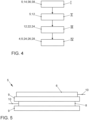
- Fig. 4
- in einem Flussdiagramm einen Verfahrensablauf zur Herstellung des Elektrodenstapels, und
- Fig. 5
- eine der Monozellen, wobei die Monozelle aus Anoden und Kathoden gebildet ist.
- Einander entsprechende Teile und Größen sind in allen Figuren stets mit gleichen Bezugszeichen versehen.
- In den
Figuren 1 und2a und 2s ist eine erste Variante einer Vorrichtung 2 dargestellt, welche der Herstellung eines Elektrodenstapels 4 aus Monozellen 5 dient. Eine der Monozellen ist in derFig. 5 dargestellt. Die Monozelle 5 ist dabei aus einer Anode 6 und einer Kathode 8 gebildet, wobei zwischen der Anode 6 und der Kathode 8 ein Separator 9 angeordnet ist. Weiterhin ist auf der der Anode 6 abgewandten Seite der Kathode 8 ein weiterer Separator 9 angeordnet. Dabei sind die Anode 6, die Kathode 8 sowie die Separatoren 9 mittels Laminieren miteinander gefügt. Die Anoden 6 und die Kathoden 8 sind dabei blattförmig ausgebildet. Des Weiteren weisen die Anode 6 und die Kathode 8 jeweils eine elektrische Kontaktierung 10 auf, welche auch als Tab bezeichnet werden. Zum Zwecke einer verbesserten Übersichtlichkeit ist die Monozelle 5 in denFiguren 1 bis 3b vereinfacht dargestellt. - Der Elektrodenstapel 4 ist dabei für eine nicht weiter dargestellte Lithium-Ionen-Batterie, beispielsweise für eine (Traktions-)Batterie eines elektrisch angetriebenen Kraftfahrzeugs vorgesehen. Die Vorrichtung 2 weist ein Stapelrad 12 auf, welches um eine Drehachse D rotatorisch antreibbar (drehantreibbar) ist.
- Das Stapelrad 12 weist umfangsseitig eingebrachte und sich in Axialrichtung A, also entlang der Drehachse D, erstreckende Aufnahmen 14 für die Monozelle 5 auf. Die Aufnahmen 14 sind dabei mittels sich vom Bereich der Drehachse D zur Umfangsseite des Stapelrads 12 hin, also nach außen, erstreckenden Armen 16, welche auch als Schaufeln bezeichnet werden, gebildet. Die Arme 16 und somit auch die Aufnahmen 14 sind in einer Ebene senkrecht zur Drehachse D spiralförmig ausgebildet. Also weisen die Aufnahmen 14 in dieser Ebene einen spiralförmigen Querschnitt auf. Dabei wird eine Krümmung der bogenförmigen Aufnahme von der Umfangsseite zur Drehachse D hin, also mit kleiner werdendem Radialabstand zur Drehachse D, größer. Weiterhin erstrecken sich die Aufnahmen 14 nach außen entgegen der mittels eines entsprechenden Pfeils um die Drehachse D repräsentierten Drehrichtung des Stapelrads 12.
- Das Stapelrad 12 weist endseitig bezüglich der Axialrichtung A jeweils eine Wandung 18 auf, welche die Aufnahmen 14 begrenzt. Dabei ist in der
Fig. 1 zum Zwecke einer Erkennbarkeit die in Blickrichtung vordere Wandung 18 nicht dargestellt. Die Wandung 18 verhindert eine undefinierte Verstellung der Monozellen 5 in einer Richtung entlang der Drehachse D bei der Rotation des Stapelrads 12 sowie im Zuge der Aufnahme der Monozellen 5 in die Aufnahmen 14. - Wie insbesondere in den
Figuren 2a und 2b erkennbar ist, weist das Stapelrad 12 eine umfangsseitige Aussparung 20 auf, welche in Umfangsrichtung des Stapelrads 12 durchgehend ist. Die Aussparung 20 erstreckt sich also in einer Ebene senkrecht zur Drehachse D. Die Aussparung 20 weist des Weiteren eine Ausdehnung entgegen der Radialrichtung R zur Drehachse D auf, welche größer als die Ausdehnung der Aufnahmen 14 in dieser Richtung ist. Somit sind die Arme 16 in Axialrichtung A nicht durchgehend. - In der Aussparung 20 ist ein Abstreifarm 22 angeordnet, wobei in der
Fig. 1 derjenige Abschnitt des Abstreifarms 22, welcher innerhalb der Aussparung 20 angeordnet ist, strichpunktiert dargestellt ist. Der Abstreifarm 22 dient als Anschlag für die in den Aufnahmen 14 aufgenommenen Monozellen 5. Bei der Rotation des Stapelrads 12 werden die in den Aufnahmen 14 angeordneten Monozellen 5 gegen den Abstreifarm 22 verstellt, so dass diese gegen eine weitere Förderung mittels des Stapelrad 12 gehalten werden. Aufgrund der weiteren Rotation des Stapelrad 12 werden die Monozellen 5 aus der jeweiligen Aufnahme 14 und in ein im Bereich des Abstreifarms 22 angeordnetes Stapelfach 24 überführt. - Zur zueinander fluchtenden Ausrichtung der Monozellen 5 weist das Stapelfach 24 einen Schieber 26 auf. Dieser ist hierzu zum Abstreifarm 22 hin verfahrbar, was in der
Fig. 1 mittels eines Doppelpfeils dargestellt ist. Weiterhin weist das Stapelfach 24 eine Kompressionseinheit 28 zur Erzeugung einer Presskraft auf die im Stapelfach 24 gestapelten und zueinander fluchtend ausgerichteten Monozellen 5 auf. Der Kompressionseinheit 28 ist hierzu durch die Aussparung 20 schwenkbar. Durch das zueinander fluchtende Ausrichten und das miteinander Verpressen der Monozellen 5 wird der Elektrodenstapel 4 gebildet. - Gemäß einer nicht weiter dargestellten Variante des Stapelfachs 24 ist die Kompressionseinheit 28 in Axialrichtung A verstellbar, so dass die Kompressionseinheit 28 nicht durch die Aussparung 20 hindurch geschwenkt, sondern zwischen dem Stapelrad 12 und einem Boden 29 des Stapelfachs 24 verfahren werden kann.
- Das Stapelfach 24 ist weiterhin zusammen mit der Kompressionseinheit 28 und mit dem Abstreifarm 22 um eine parallel zur Drehachse D orientierte Kippachse K kippbar, so dass der Elektrodenstapel 4 aus dem Stapelfach entnommen werden und mittels eines Transportbandes 30 abtransportiert werden kann. Mittels des Transportbands 30 kann der Elektrodenstapel 4, also die gegeneinander verpressten Monozellen 5 zur weiteren Herstellung der Batterie oder zu einem Magazin oder einem Lager transportiert werden.
- In der
Figur 1 ist die Vorrichtung 2 mit Blickrichtung entlang der Drehachse D und in denFiguren 2a und 2b mit Blickrichtung senkrecht zur Drehachse D gezeigt und parallel bzw. senkrecht zum Boden des Stapelfachs 29. Dabei ist in denFiguren 2a und 2b zum Zwecke einer verbesserten Übersichtlichkeit der Abstreifarm 22 vereinfacht dargestellt. - Wie insbesondere in der
Fig. 2b zu erkennen ist, weist der Schieber 26 sowie der Abstreifarm 22 jeweils eine Kontaktierungsaufnahme 32 für die elektrischen Kontaktierungen 10 der Anoden 6 und der Kathoden 8 der Monozellen 5 auf. - Des Weiteren weist die Vorrichtung 2 eine Fördereinrichtung 34 zum Fördern der Monozellen 5 in die Aufnahmen 14 des Stapelrads 12 auf. Die Fördereinrichtung 34 weist dabei zwei erste Förderbänder 36 auf, mittels welchen zwei der Monozellen 5 gleichzeitig in die Aufnahmen 14 des Stapelrads 12 gefördert werden können. Weiterhin ist jedem der ersten Förderbänder 36 ein zweites Förderband 38 zugeordnet, wobei das jeweilige zweite Förderband 38 parallel zum zugeordneten ersten Förderband 36 angeordnet ist. Der Fördergurt 40 des jeweiligen zweiten Förderbands 38 weist dabei eine entgegengesetzte Umlaufrichtung zum Fördergurt 40 des zugeordneten ersten Förderbands 36 auf. Die ersten Förderbänder 36 und die zugeordneten zweiten Förderbänder 38 sind jeweils derart zueinander beabstandet, dass die Monozellen 5 bei deren Förderung zwischen dem ersten Förderband 36 und dem entsprechenden zweiten Förderband 38 eingespannt sind.
- Die ersten Förderbänder 36 ragen dabei abschnittsweise in die Aussparung 20 des Stapelrads 12, sodass die Monozellen tangential in die Aufnahme 14 gefördert werden. Diejenigen Abschnitte der Förderbänder 36 bzw. 38, welcher in die Aussparung 20 hineinragen, sind dabei strichliniert dargestellt.
- Wie insbesondere in der
Fig. 2a zu erkennen ist, weisen die ersten Förderbänder 36 und die zweiten Förderbänder 38 in einer Richtung, welche senkrecht zur Förderrichtung und in der mittels deren Fördergurte 40 aufgespannten Ebenen verläuft, eine kleinere Ausdehnung als die Monozellen 5 auf. Mit anderen Worten ragen die Monozellen 5 in Förderbandquerrichtung über die Förderbänder 38 hinaus. - In den
Figuren 3a und 3b ist eine zweite Variante der Vorrichtung 2 dargestellt. Mit Ausnahme des im Folgenden dargestellten, gelten für die zweite Variante die oben dargelegten Ausführungen analog und werden hier nicht weiter dargestellt. - Die Vorrichtung 2 weist zwei Abstreifarme 22 auf, welche in Axialrichtung A beidseitig des Stapelrads 12 angeordnet sind. Mit anderen Worten ist einer der beiden Abstreifarme bezüglich der Axialrichtung A vor und der andere Abstreifarm 22 hinter dem Stapelrad 12 angeordnet. Dabei weist das Stapelrad 12 eine kleinere Ausdehnung in Axialrichtung A auf, so dass die in den Aufnahmen 14 aufgenommenen Monozellen 5 in Axialrichtung A beidseitig über das Stapelrad 12 hinausragen. Die beiden Abstreifarme 22 bilden bei einer Rotation des Stapelrads 12 einen Anschlag für die in den Aufnahmen 14 aufgenommenen Monozellen 5. Die Monozellen 5 werden folglich gegen eine weitere Förderung aufgrund der Rotation des Stapelrads 12 gestützt und aus der jeweiligen Aufnahme 14 in das Stapelfach 24 überführt.
- Im Vergleich zur ersten Variante weist das Stapelrad 12 also keine Wandung 18 auf, welche die Aufnahmen 14 endseitig bezüglich der Axialrichtung A abschließt.
- Die Abstreifarme 22 weisen weiterhin keine Kontaktierungsaufnahme 32 für die elektrischen Kontaktierungen 10 der Anoden oder der Kathoden auf. Vielmehr sind die elektrischen Kontaktierungen 10 zwischen den Armen 16 des Stapelrads angeordnet.
- Das in der
Fig. 4 gezeigte Flussdiagramm repräsentiert ein Verfahren zur Herstellung eines Elektrodenstapels 4 aus den Monozellen 5. Vorzugsweise wird hierzu eine Vorrichtung 2 gemäß denFiguren 1 und2 herangezogen. - In einem ersten Schritt I werden die Monozellen 5 in die Aufnahmen 14 des, insbesondere kontinuierlich, rotatorisch angetriebenen Stapelrads 12 gefördert. Hierbei werden mindestens zwei der Monozellen 5 gleichzeitig in die jeweilige Aufnahme 14 des Stapelrads 12 gefördert. Hierzu weist die Vorrichtung 2, wie oben dargelegt, zwei erste Förderbänder 36 auf.
- Dabei wird in jeder der Aufnahmen 14 lediglich eine einzige Monozelle aufgenommen, wobei derart in die Aufnahmen 14 eingebracht sind, dass in Umfangsrichtung (Umlaufrichtung) des Stapelrads 12 die Anoden 6 und die Kathoden 8 der Monozellen 5 alternierend angeordnet sind.
- Die elektrischen Kontaktierungen 10 der Anoden 6 und der Kathoden 8 der Monozellen 5 sind dabei bezüglich deren Förderrichtung in die jeweilige Aufnahme 14 des Stapelrads 12 vorne bzw. hinten angeordnet. Auf diese Weise sind die elektrischen Kontaktierungen 10 der Anoden 6 und der Kathoden 8 an einander gegenüberliegenden Seiten des Elektrodenstapels 4 angeordnet.
- In einem zweiten Schritt II werden die in den Aufnahmen 14 aufgenommenen Monozellen 5 anhand einer Rotation des Stapelrads 12 zu einem Stapelfach 24 gefördert.
- In einem dritten Schritt III des Verfahrens werden die Monozellen 5 mittels des Abstreifarms 22 oder mittels der Abstreifarme 22 im Bereich des Stapelfachs 24 gehalten. Also werden die Monozellen 5 mittels des Abstreifarms 22 bzw. mittels der Abstreifarme 22 gegen die Rotation des Stapelrads 12 gehalten (gestützt), sodass die jeweilige Aufnahme 14 aufgrund der Rotation des Stapelrads 12 relativ zur zugeordneten Monozelle 5 verstellt und entsprechend die Monozelle 5 aus der jeweiligen Aufnahme 14 in das Stapelfach 24 überführt wird. Dabei werden die Monozellen alternierend im Stapelfach 24 übereinandergestapelt.
- Weiterhin ist die Fördergeschwindigkeit der Monozellen 5 in die jeweilige Aufnahme 14 des Stapelrads 12 derart eingestellt, dass die Monozellen 5 zeitlich vor dem Halten durch den Abstreifarm 22 oder die Abstreifarme 22 aufgrund einer Reibung zwischen den Monozellen 5 und der jeweiligen Aufnahme 14 relativ zu dieser in den Stillstand abgebremst wird. Die Einstellung der Fördergeschwindigkeit erfolgt dabei in Abhängigkeit der Form der Aufnahmen 14. Aufgrund der Spiralform der Aufnahmen 14 wird eine Reibungskraft zwischen der jeweiligen Aufnahme 14 und der Monozelle 5 zum (drehachsenseitigen) der Drehachse D zugewandten Ende der Aufnahme 14 größer.
- In einem vierten Schritt IV werden unter Bildung des Elektrodenstapels 4 die gestapelten Monozellen 5 im Stapelfach 24 mittels des Schiebers 26 fluchtend zueinander ausgerichtet und mittels der Kompressionseinheit 28 gegeneinander verpresst. Hierzu wirkt die Kompressionseinheit 28 mit einer Presskraft auf die im Stapelfach 24 gestapelten und fluchtend zueinander ausgerichteten Monozellen 5 ein.
- Die Erfindung ist nicht auf das vorstehend beschriebene Ausführungsbeispiel beschränkt. Vielmehr können auch andere Varianten der Erfindung vom Fachmann hieraus abgeleitet werden, ohne den Gegenstand der Erfindung zu verlassen. Insbesondere sind ferner alle im Zusammenhang mit dem Ausführungsbeispiel beschriebenen Einzelmerkmale auch auf andere Weise miteinander kombinierbar, ohne den Gegenstand der Erfindung zu verlassen.
-
- 2
- Vorrichtung
- 4
- Elektrodenstapel
- 5
- Monozelle
- 6
- Anode
- 8
- Kathode
- 9
- Separator
- 10
- elektrische Kontaktierung der Elektrode
- 12
- Stapelrad
- 14
- Aufnahme
- 16
- Arm
- 18
- Wandung
- 20
- Aussparung
- 22
- Abstreifarm
- 24
- Stapelfach
- 26
- Schieber
- 28
- Kompressionseinheit
- 29
- Boden des Stapelfachs
- 30
- Transportband
- 32
- Kontaktierungsaufnahmen
- 34
- Fördereinrichtung
- 36
- erstes Förderband
- 38
- zweites Förderband
- 40
- Fördergurt
- I
- Fördern der Monozellen in die Aufnahmen des Stapelrads
- II
- Fördern der Monozellen zum Stapelfach mittels des Stapelrads
- III
- Überführen Monozellen aus der Aufnahme in das Stapelfach
- IV
- Gegeneinander Verpressen der Monozellen
- A
- Axialrichtung
- D
- Drehachse
- K
- Kippachse
Claims (10)
- Verfahren zur Herstellung eines Elektrodenstapels (4) aus Monozellen (5) für eine Lithium-Ionen-Batterie, insbesondere eines elektrisch angetriebenen Kraftfahrzeugs, wobei die Monozellen (5) jeweils aus einer Anode (6) und einer Kathode (8) gebildet sind,- bei dem die Monozellen (5) in Aufnahmen (14) eines rotatorisch angetriebenen oder rotatorisch antreibbaren Stapelrads (12) gefördert werden,- bei dem die in den Aufnahmen (14) aufgenommenen Monozellen (5) anhand einer Rotation des Stapelrads (12) zu einem Stapelfach (24) gefördert werden,- bei dem die Monozellen (5) mittels eines Abstreifarms (22) im Bereich des Stapelfachs (24) gehalten und aufgrund der Rotation des Stapelrads (12) aus der jeweiligen Aufnahme (14) in das Stapelfach (24) überführt werden, wobei die Monozellen (5) im Stapelfach (24) gestapelt werden, und- bei dem die gestapelten Monozellen (5) im Stapelfach (24) gegeneinander verpresst werden.
- Verfahren nach Anspruch 1,
dadurch gekennzeichnet,
dass mindestens zwei der Monozellen (5) gleichzeitig in die entsprechenden Aufnahmen (14) des Stapelrads (12) gefördert werden. - Verfahren nach Anspruch 1 oder 2,
dadurch gekennzeichnet,
dass die Fördergeschwindigkeit der Monozellen (5) in die jeweiligen Aufnahmen (14) des Stapelrads (12) derart eingestellt ist, dass die Monozellen (5) zeitlich vor dem Halten durch den Abstreifarm (22) aufgrund einer Reibung relativ zur jeweiligen Aufnahme (14) in einen Stillstand abgebremst werden. - Vorrichtung (2) zur Herstellung eines Elektrodenstapels (4) aus Monozellen (5) für eine Lithium-Ionen-Batterie, insbesondere gemäß dem Verfahren nach einem der Ansprüche 1 bis 3, aufweisend- ein um eine Drehachse (D) rotatorisch antreibbares Stapelrad (12) mit umfangsseitig eingebrachten und sich in Axialrichtung (A) erstreckenden Aufnahmen (14) für die Monozellen (5),- eine Fördereinrichtung (34) zum Fördern der Monozellen (5) in die Aufnahmen (14) des Stapelrads (12),- einen Abstreifarm (22), welcher in eine in Umfangsrichtung des Stapelrades (12) durchgehende Aussparung (20) einbringbar ist, und welcher bei einer Rotation des Stapelrads (12) einen Anschlag für die in den Aufnahmen (14) aufgenommenen Monozellen (5) bildet, so dass die Monozellen (5) aufgrund der Rotation des Stapelrads (12) aus der jeweiligen Aufnahme (14) in ein Stapelfach (24) überführt werden, oder- zwei Abstreifarme (22), welche in Axialrichtung (A) beidseitig des Stapelrads (12) angeordnet sind, wobei das Stapelrad (12) eine kleinere Ausdehnung in Axialrichtung (A) aufweist als die Monozellen (5), so dass die Abstreifarme (22) bei einer Rotation des Stapelrads (12) einen Anschlag für die in den Aufnahmen (14) aufgenommenen und in Axialrichtung (A) aus den Aufnahmen (14) hinausragenden Monozellen (5) bilden und die Monozellen (5) aufgrund der Rotation des Stapelrads (12) aus der jeweiligen Aufnahme (14) in ein Stapelfach (24) überführt werden, und- wobei das Stapelfach (24) eine Kompressionseinheit (28) zur Erzeugung einer Presskraft auf die im Stapelfach (24) gestapelten Monozellen (5) aufweist.
- Vorrichtung (2) nach Anspruch 4,
dadurch gekennzeichnet,
dass die Aufnahmen (14) in einer Ebene senkrecht zur Drehachse (D) bogenförmig, insbesondere spiralförmig, ausgebildet sind. - Vorrichtung (2) nach Anspruch 4 oder 5,
dadurch gekennzeichnet,
dass die Fördereinrichtung (34) zum Fördern der Monozellen (5) in die Aufnahmen (14) des Stapelrads (12) mindestens zwei erste Förderbänder (36) aufweist. - Vorrichtung (2) nach Anspruch 6,
dadurch gekennzeichnet,
dass für jedes der ersten Förderbänder (36) ein parallel orientiertes zweites Förderband (38) mit zum zugeordneten ersten Förderband (36) entgegengesetzter Umlaufrichtung vorgesehen ist, so dass Monozellen (5) beim deren Fördervorgang zwischen dem ersten Förderband (36) und dem zweiten Förderband (38) eingespannt sind. - Vorrichtung (2) nach Anspruch 7,
dadurch gekennzeichnet,
dass die ersten Förderbänder (36) und/oder die zweiten Förderbänder (38) in die oder eine Aussparung (20) des Stapelrads (12) hineinragen, sodass die Monozellen (5) tangential in die Aufnahme (14) gefördert werden. - Vorrichtung (2) nach einem der Ansprüche 4 bis 8,
dadurch gekennzeichnet,
dass das Stapelfach (24) zur Entnahme des Elektrodenstapels (4), insbesondere zusammen mit der Kompressionseinheit (28), verfahrbar und/oder um eine zur Drehachse (D) parallele Kippachse (K) kippbar ist. - Vorrichtung (2) nach einem der Ansprüche 4 bis 9,
dadurch gekennzeichnet,
dass ein zur zueinander fluchtenden Ausrichtung der Monozellen (5) vorgesehener Schieber (26) des Stapelfachs (24) und/oder der Abstreifarm (22) jeweils eine Kontaktierungsaufnahme (32) für elektrische Kontaktierungen (10) der Anoden (6) und der Kathoden (8) der Monozelle (5) aufweist.
Applications Claiming Priority (2)
| Application Number | Priority Date | Filing Date | Title |
|---|---|---|---|
| DE102019205427.7A DE102019205427A1 (de) | 2019-04-15 | 2019-04-15 | Verfahren und Vorrichtung zur Herstellung eines Elektrodenstapels |
| PCT/EP2020/060412 WO2020212317A1 (de) | 2019-04-15 | 2020-04-14 | Verfahren und vorrichtung zur herstellung eines elektrodenstapels |
Publications (2)
| Publication Number | Publication Date |
|---|---|
| EP3942641A1 EP3942641A1 (de) | 2022-01-26 |
| EP3942641B1 true EP3942641B1 (de) | 2023-06-14 |
Family
ID=70292957
Family Applications (1)
| Application Number | Title | Priority Date | Filing Date |
|---|---|---|---|
| EP20719605.6A Active EP3942641B1 (de) | 2019-04-15 | 2020-04-14 | Verfahren und vorrichtung zur herstellung eines elektrodenstapels |
Country Status (6)
| Country | Link |
|---|---|
| US (1) | US20220216502A1 (de) |
| EP (1) | EP3942641B1 (de) |
| KR (1) | KR20210150517A (de) |
| CN (1) | CN114207893A (de) |
| DE (1) | DE102019205427A1 (de) |
| WO (1) | WO2020212317A1 (de) |
Families Citing this family (7)
| Publication number | Priority date | Publication date | Assignee | Title |
|---|---|---|---|---|
| DE102021001545A1 (de) | 2021-03-24 | 2022-09-29 | Giesecke+Devrient Currency Technology Gmbh | Stapelrad und Vorrichtung zur Stapelung von flächigen Gegenständen |
| DE102021001817A1 (de) | 2021-04-08 | 2022-10-13 | Giesecke+Devrient Currency Technology Gmbh | Vorrichtung zur Stapelung von flächigen Gegenständen |
| DE102021001820A1 (de) | 2021-04-08 | 2022-10-13 | Giesecke+Devrient Currency Technology Gmbh | Verfahren und Vorrichtung zur Stapelung von flächigen Gegenständen |
| DE102021207342A1 (de) | 2021-07-12 | 2023-01-12 | Körber Technologies Gmbh | Zellstapelanlage und Zellstapelvorrichtung für Segmente von Energiezellen und Teilvorrichtung/Teilverfahren einer oder in einer Zellstapelanlage |
| DE102022105396A1 (de) * | 2022-03-08 | 2023-09-14 | Körber Technologies Gmbh | Zellstapelanlage zum Stapeln von Segmenten von Energiezellen, Verfahren zur Steuerung einer derartigen Zellstapelanlage, Teilvorrichtung einer oder in einer Zellstapelanlage und Teilverfahren beim Herstellen von Zellstapeln in einer Zellstapelanlage |
| WO2024088905A1 (de) | 2022-10-25 | 2024-05-02 | Volkswagen Ag | Vorrichtung und entsprechendes verfahren zur herstellung eines elektrodenstapels aus elektrodenstapelelementen |
| DE102022211988A1 (de) | 2022-10-25 | 2024-04-25 | Giesecke+Devrient Currency Technology Gmbh | Vorrichtung und Verfahren zur Herstellung eines Elektrodenstapels |
Family Cites Families (5)
| Publication number | Priority date | Publication date | Assignee | Title |
|---|---|---|---|---|
| JPS5469729A (en) * | 1977-11-11 | 1979-06-05 | Arekusandorobuitsuchi Kor Iwan | Method of incorporating battery electrode row body and its device |
| JP5997877B2 (ja) * | 2011-04-07 | 2016-09-28 | 株式会社京都製作所 | 積層装置および積層方法 |
| DE102012006303B4 (de) * | 2012-03-21 | 2015-07-09 | Audi Ag | Batterie für ein Fahrzeug und Verfahren zum Fertigen einer solchen Batterie |
| US9368827B2 (en) * | 2013-08-21 | 2016-06-14 | GM Global Technology Operations LLC | Horizontal high speed stacking for batteries with prismatic cans |
| DE102016007706B4 (de) * | 2016-06-23 | 2020-03-26 | Daimler Ag | Verfahren und Vorrichtung zum Herstellen wenigstens eines Brennstoffzellenstapels |
-
2019
- 2019-04-15 DE DE102019205427.7A patent/DE102019205427A1/de active Pending
-
2020
- 2020-04-14 EP EP20719605.6A patent/EP3942641B1/de active Active
- 2020-04-14 US US17/603,837 patent/US20220216502A1/en active Pending
- 2020-04-14 KR KR1020217036497A patent/KR20210150517A/ko unknown
- 2020-04-14 CN CN202080040740.1A patent/CN114207893A/zh active Pending
- 2020-04-14 WO PCT/EP2020/060412 patent/WO2020212317A1/de unknown
Also Published As
| Publication number | Publication date |
|---|---|
| US20220216502A1 (en) | 2022-07-07 |
| CN114207893A (zh) | 2022-03-18 |
| EP3942641A1 (de) | 2022-01-26 |
| KR20210150517A (ko) | 2021-12-10 |
| DE102019205427A1 (de) | 2020-10-15 |
| WO2020212317A1 (de) | 2020-10-22 |
Similar Documents
| Publication | Publication Date | Title |
|---|---|---|
| EP3942627B1 (de) | Verfahren und vorrichtung zur herstellung eines elektrodenstapels | |
| EP3942641B1 (de) | Verfahren und vorrichtung zur herstellung eines elektrodenstapels | |
| DE102017216138A1 (de) | Verfahren zur Herstellung eines Elektrodenstapels für eine Batteriezelle und Batteriezelle | |
| WO2019052881A1 (de) | Verfahren zum trennen bandförmigen elektroden- und separatormaterials auf einer gekrümmten oberfläche unter verwendung eines laserstrahles | |
| EP3878030B1 (de) | Verfahren zur herstellung einer kathodenvorrichtung, verfahren zur herstellung eines elektrodenverbundes und batterie | |
| EP3878041B1 (de) | Verfahren und vorrichtung zur herstellung eines elektrodenstapels | |
| DE102021207364A1 (de) | Maschine, Verfahren und Zwischenprodukt für die Energiezellen produzierende Industrie | |
| WO2012000679A1 (de) | Verfahren zum stapeln von blättern, insbesondere zur fertigung einer lithium-ionen-batterie | |
| DE102021207357A1 (de) | Maschine und Verfahren für die Energiezellen produzierende Industrie | |
| WO2020147869A1 (de) | Batteriezellenmodul, positioniervorrichtung zur herstellung von batteriezellenmodulen und verfahren zur herstellung von batteriezellenmodulen | |
| EP3890082A1 (de) | Kontinuierliches stapeln von zuschnitten mindestens einer folien- oder membran-artigen warenbahn auf einen stapel | |
| DE102010055617A1 (de) | Verfahren zum Herstellen eines Elektrodenstapels aus Kathode, Anode und Separator | |
| WO2022199885A1 (de) | Verfahren und vorrichtung zum herstellen eines elektrodenstapels | |
| WO2022214221A1 (de) | Verfahren und vorrichtung zum bilden eines stapels von flächigen elementen für einen energiespeicher oder eine brennstoffzelle | |
| DE102021001854A1 (de) | Verfahren und Vorrichtung zum Bilden eines Stapels von flächigen Elementen für einen Energiespeicher oder eine Brennstoffzelle | |
| DE102022211988A1 (de) | Vorrichtung und Verfahren zur Herstellung eines Elektrodenstapels | |
| WO2024088905A1 (de) | Vorrichtung und entsprechendes verfahren zur herstellung eines elektrodenstapels aus elektrodenstapelelementen | |
| DE102017216149A1 (de) | Verfahren und Vorrichtung zur Herstellung eines Elektrodenstapels für eine Batteriezelle | |
| WO2023052613A1 (de) | Vorrichtung und verfahren zur herstellung einer elektrode | |
| DE102017216151A1 (de) | Werkstückträger zum Transport eines mehrlagigen Elektrodenstapels | |
| DE102017216188A1 (de) | Verfahren zur Herstellung eines Elektrodenstapels für eine Batteriezelle und Batteriezelle | |
| WO2023025440A1 (de) | Verfahren zum herstellen eines stapels von elektrodenblättern sowie schneidvorrichtung und abstandselement, ablängeinrichtung dafür | |
| DE102021001817A1 (de) | Vorrichtung zur Stapelung von flächigen Gegenständen | |
| DE102021001818A1 (de) | Verfahren und Vorrichtung zum Herstellen eines Elektrodenstapels | |
| WO2022199887A1 (de) | Verfahren zum erzeugen eines elektrodenstapels und stapelvorrichtung mit ausschubelement |
Legal Events
| Date | Code | Title | Description |
|---|---|---|---|
| STAA | Information on the status of an ep patent application or granted ep patent |
Free format text: STATUS: UNKNOWN |
|
| STAA | Information on the status of an ep patent application or granted ep patent |
Free format text: STATUS: THE INTERNATIONAL PUBLICATION HAS BEEN MADE |
|
| PUAI | Public reference made under article 153(3) epc to a published international application that has entered the european phase |
Free format text: ORIGINAL CODE: 0009012 |
|
| STAA | Information on the status of an ep patent application or granted ep patent |
Free format text: STATUS: REQUEST FOR EXAMINATION WAS MADE |
|
| 17P | Request for examination filed |
Effective date: 20211019 |
|
| AK | Designated contracting states |
Kind code of ref document: A1 Designated state(s): AL AT BE BG CH CY CZ DE DK EE ES FI FR GB GR HR HU IE IS IT LI LT LU LV MC MK MT NL NO PL PT RO RS SE SI SK SM TR |
|
| GRAP | Despatch of communication of intention to grant a patent |
Free format text: ORIGINAL CODE: EPIDOSNIGR1 |
|
| STAA | Information on the status of an ep patent application or granted ep patent |
Free format text: STATUS: GRANT OF PATENT IS INTENDED |
|
| RIC1 | Information provided on ipc code assigned before grant |
Ipc: B65H 31/34 20060101ALI20221024BHEP Ipc: B65H 29/40 20060101ALI20221024BHEP Ipc: H01M 10/052 20100101ALI20221024BHEP Ipc: H01M 10/04 20060101AFI20221024BHEP |
|
| INTG | Intention to grant announced |
Effective date: 20221117 |
|
| GRAS | Grant fee paid |
Free format text: ORIGINAL CODE: EPIDOSNIGR3 |
|
| GRAA | (expected) grant |
Free format text: ORIGINAL CODE: 0009210 |
|
| STAA | Information on the status of an ep patent application or granted ep patent |
Free format text: STATUS: THE PATENT HAS BEEN GRANTED |
|
| AK | Designated contracting states |
Kind code of ref document: B1 Designated state(s): AL AT BE BG CH CY CZ DE DK EE ES FI FR GB GR HR HU IE IS IT LI LT LU LV MC MK MT NL NO PL PT RO RS SE SI SK SM TR |
|
| RAP1 | Party data changed (applicant data changed or rights of an application transferred) |
Owner name: VOLKSWAGEN AG |
|
| REG | Reference to a national code |
Ref country code: CH Ref legal event code: EP |
|
| REG | Reference to a national code |
Ref country code: DE Ref legal event code: R096 Ref document number: 502020003793 Country of ref document: DE |
|
| REG | Reference to a national code |
Ref country code: AT Ref legal event code: REF Ref document number: 1579878 Country of ref document: AT Kind code of ref document: T Effective date: 20230715 |
|
| REG | Reference to a national code |
Ref country code: LT Ref legal event code: MG9D |
|
| REG | Reference to a national code |
Ref country code: NL Ref legal event code: MP Effective date: 20230614 |
|
| PG25 | Lapsed in a contracting state [announced via postgrant information from national office to epo] |
Ref country code: SE Free format text: LAPSE BECAUSE OF FAILURE TO SUBMIT A TRANSLATION OF THE DESCRIPTION OR TO PAY THE FEE WITHIN THE PRESCRIBED TIME-LIMIT Effective date: 20230614 Ref country code: NO Free format text: LAPSE BECAUSE OF FAILURE TO SUBMIT A TRANSLATION OF THE DESCRIPTION OR TO PAY THE FEE WITHIN THE PRESCRIBED TIME-LIMIT Effective date: 20230914 Ref country code: ES Free format text: LAPSE BECAUSE OF FAILURE TO SUBMIT A TRANSLATION OF THE DESCRIPTION OR TO PAY THE FEE WITHIN THE PRESCRIBED TIME-LIMIT Effective date: 20230614 |
|
| PG25 | Lapsed in a contracting state [announced via postgrant information from national office to epo] |
Ref country code: RS Free format text: LAPSE BECAUSE OF FAILURE TO SUBMIT A TRANSLATION OF THE DESCRIPTION OR TO PAY THE FEE WITHIN THE PRESCRIBED TIME-LIMIT Effective date: 20230614 Ref country code: NL Free format text: LAPSE BECAUSE OF FAILURE TO SUBMIT A TRANSLATION OF THE DESCRIPTION OR TO PAY THE FEE WITHIN THE PRESCRIBED TIME-LIMIT Effective date: 20230614 Ref country code: LV Free format text: LAPSE BECAUSE OF FAILURE TO SUBMIT A TRANSLATION OF THE DESCRIPTION OR TO PAY THE FEE WITHIN THE PRESCRIBED TIME-LIMIT Effective date: 20230614 Ref country code: LT Free format text: LAPSE BECAUSE OF FAILURE TO SUBMIT A TRANSLATION OF THE DESCRIPTION OR TO PAY THE FEE WITHIN THE PRESCRIBED TIME-LIMIT Effective date: 20230614 Ref country code: HR Free format text: LAPSE BECAUSE OF FAILURE TO SUBMIT A TRANSLATION OF THE DESCRIPTION OR TO PAY THE FEE WITHIN THE PRESCRIBED TIME-LIMIT Effective date: 20230614 Ref country code: GR Free format text: LAPSE BECAUSE OF FAILURE TO SUBMIT A TRANSLATION OF THE DESCRIPTION OR TO PAY THE FEE WITHIN THE PRESCRIBED TIME-LIMIT Effective date: 20230915 |
|
| PG25 | Lapsed in a contracting state [announced via postgrant information from national office to epo] |
Ref country code: FI Free format text: LAPSE BECAUSE OF FAILURE TO SUBMIT A TRANSLATION OF THE DESCRIPTION OR TO PAY THE FEE WITHIN THE PRESCRIBED TIME-LIMIT Effective date: 20230614 |
|
| PG25 | Lapsed in a contracting state [announced via postgrant information from national office to epo] |
Ref country code: SK Free format text: LAPSE BECAUSE OF FAILURE TO SUBMIT A TRANSLATION OF THE DESCRIPTION OR TO PAY THE FEE WITHIN THE PRESCRIBED TIME-LIMIT Effective date: 20230614 |
|
| PG25 | Lapsed in a contracting state [announced via postgrant information from national office to epo] |
Ref country code: IS Free format text: LAPSE BECAUSE OF FAILURE TO SUBMIT A TRANSLATION OF THE DESCRIPTION OR TO PAY THE FEE WITHIN THE PRESCRIBED TIME-LIMIT Effective date: 20231014 |
|
| PG25 | Lapsed in a contracting state [announced via postgrant information from national office to epo] |
Ref country code: SM Free format text: LAPSE BECAUSE OF FAILURE TO SUBMIT A TRANSLATION OF THE DESCRIPTION OR TO PAY THE FEE WITHIN THE PRESCRIBED TIME-LIMIT Effective date: 20230614 Ref country code: SK Free format text: LAPSE BECAUSE OF FAILURE TO SUBMIT A TRANSLATION OF THE DESCRIPTION OR TO PAY THE FEE WITHIN THE PRESCRIBED TIME-LIMIT Effective date: 20230614 Ref country code: RO Free format text: LAPSE BECAUSE OF FAILURE TO SUBMIT A TRANSLATION OF THE DESCRIPTION OR TO PAY THE FEE WITHIN THE PRESCRIBED TIME-LIMIT Effective date: 20230614 Ref country code: PT Free format text: LAPSE BECAUSE OF FAILURE TO SUBMIT A TRANSLATION OF THE DESCRIPTION OR TO PAY THE FEE WITHIN THE PRESCRIBED TIME-LIMIT Effective date: 20231016 Ref country code: IS Free format text: LAPSE BECAUSE OF FAILURE TO SUBMIT A TRANSLATION OF THE DESCRIPTION OR TO PAY THE FEE WITHIN THE PRESCRIBED TIME-LIMIT Effective date: 20231014 Ref country code: EE Free format text: LAPSE BECAUSE OF FAILURE TO SUBMIT A TRANSLATION OF THE DESCRIPTION OR TO PAY THE FEE WITHIN THE PRESCRIBED TIME-LIMIT Effective date: 20230614 Ref country code: CZ Free format text: LAPSE BECAUSE OF FAILURE TO SUBMIT A TRANSLATION OF THE DESCRIPTION OR TO PAY THE FEE WITHIN THE PRESCRIBED TIME-LIMIT Effective date: 20230614 |
|
| VS25 | Lapsed in a validation state [announced via postgrant information from nat. office to epo] |
Ref country code: MD Free format text: LAPSE BECAUSE OF FAILURE TO SUBMIT A TRANSLATION OF THE DESCRIPTION OR TO PAY THE FEE WITHIN THE PRESCRIBED TIME-LIMIT Effective date: 20230614 |
|
| PG25 | Lapsed in a contracting state [announced via postgrant information from national office to epo] |
Ref country code: PL Free format text: LAPSE BECAUSE OF FAILURE TO SUBMIT A TRANSLATION OF THE DESCRIPTION OR TO PAY THE FEE WITHIN THE PRESCRIBED TIME-LIMIT Effective date: 20230614 |
|
| REG | Reference to a national code |
Ref country code: DE Ref legal event code: R097 Ref document number: 502020003793 Country of ref document: DE |
|
| PLBE | No opposition filed within time limit |
Free format text: ORIGINAL CODE: 0009261 |
|
| STAA | Information on the status of an ep patent application or granted ep patent |
Free format text: STATUS: NO OPPOSITION FILED WITHIN TIME LIMIT |
|
| PG25 | Lapsed in a contracting state [announced via postgrant information from national office to epo] |
Ref country code: DK Free format text: LAPSE BECAUSE OF FAILURE TO SUBMIT A TRANSLATION OF THE DESCRIPTION OR TO PAY THE FEE WITHIN THE PRESCRIBED TIME-LIMIT Effective date: 20230614 |
|
| PG25 | Lapsed in a contracting state [announced via postgrant information from national office to epo] |
Ref country code: SI Free format text: LAPSE BECAUSE OF FAILURE TO SUBMIT A TRANSLATION OF THE DESCRIPTION OR TO PAY THE FEE WITHIN THE PRESCRIBED TIME-LIMIT Effective date: 20230614 |
|
| 26N | No opposition filed |
Effective date: 20240315 |