EP3942534B1 - Verfahren zur bestimmung einer zeitdifferenz - Google Patents
Verfahren zur bestimmung einer zeitdifferenz Download PDFInfo
- Publication number
- EP3942534B1 EP3942534B1 EP20702765.7A EP20702765A EP3942534B1 EP 3942534 B1 EP3942534 B1 EP 3942534B1 EP 20702765 A EP20702765 A EP 20702765A EP 3942534 B1 EP3942534 B1 EP 3942534B1
- Authority
- EP
- European Patent Office
- Prior art keywords
- motor vehicle
- rfid
- detection device
- time
- rfid device
- Prior art date
- Legal status (The legal status is an assumption and is not a legal conclusion. Google has not performed a legal analysis and makes no representation as to the accuracy of the status listed.)
- Active
Links
Images

Classifications
-
- G—PHYSICS
- G07—CHECKING-DEVICES
- G07B—TICKET-ISSUING APPARATUS; FARE-REGISTERING APPARATUS; FRANKING APPARATUS
- G07B15/00—Arrangements or apparatus for collecting fares, tolls or entrance fees at one or more control points
- G07B15/02—Arrangements or apparatus for collecting fares, tolls or entrance fees at one or more control points taking into account a variable factor such as distance or time, e.g. for passenger transport, parking systems or car rental systems
-
- B—PERFORMING OPERATIONS; TRANSPORTING
- B60—VEHICLES IN GENERAL
- B60C—VEHICLE TYRES; TYRE INFLATION; TYRE CHANGING; CONNECTING VALVES TO INFLATABLE ELASTIC BODIES IN GENERAL; DEVICES OR ARRANGEMENTS RELATED TO TYRES
- B60C19/00—Tyre parts or constructions not otherwise provided for
- B60C2019/004—Tyre sensors other than for detecting tyre pressure
-
- G—PHYSICS
- G06—COMPUTING OR CALCULATING; COUNTING
- G06K—GRAPHICAL DATA READING; PRESENTATION OF DATA; RECORD CARRIERS; HANDLING RECORD CARRIERS
- G06K19/00—Record carriers for use with machines and with at least a part designed to carry digital markings
- G06K19/06—Record carriers for use with machines and with at least a part designed to carry digital markings characterised by the kind of the digital marking, e.g. shape, nature, code
- G06K19/067—Record carriers with conductive marks, printed circuits or semiconductor circuit elements, e.g. credit or identity cards also with resonating or responding marks without active components
- G06K19/07—Record carriers with conductive marks, printed circuits or semiconductor circuit elements, e.g. credit or identity cards also with resonating or responding marks without active components with integrated circuit chips
- G06K19/077—Constructional details, e.g. mounting of circuits in the carrier
- G06K19/07749—Constructional details, e.g. mounting of circuits in the carrier the record carrier being capable of non-contact communication, e.g. constructional details of the antenna of a non-contact smart card
- G06K19/07758—Constructional details, e.g. mounting of circuits in the carrier the record carrier being capable of non-contact communication, e.g. constructional details of the antenna of a non-contact smart card arrangements for adhering the record carrier to further objects or living beings, functioning as an identification tag
- G06K19/07764—Constructional details, e.g. mounting of circuits in the carrier the record carrier being capable of non-contact communication, e.g. constructional details of the antenna of a non-contact smart card arrangements for adhering the record carrier to further objects or living beings, functioning as an identification tag the adhering arrangement making the record carrier attachable to a tyre
-
- G—PHYSICS
- G07—CHECKING-DEVICES
- G07C—TIME OR ATTENDANCE REGISTERS; REGISTERING OR INDICATING THE WORKING OF MACHINES; GENERATING RANDOM NUMBERS; VOTING OR LOTTERY APPARATUS; ARRANGEMENTS, SYSTEMS OR APPARATUS FOR CHECKING NOT PROVIDED FOR ELSEWHERE
- G07C9/00—Individual registration on entry or exit
- G07C9/20—Individual registration on entry or exit involving the use of a pass
Definitions
- the present invention relates to a method for determining a time difference according to claim 1.
- the invention is based on a method for determining a time difference.
- time differences are known from the prior art.
- time differences that can lie, for example, between the time at which a motor vehicle enters and exits a parking garage.
- the US 5 414 624 A discloses such a method.
- the WO 2018/179171 A1 reveals a similar procedure in the context of toll collection, in which, however, no time difference is determined.
- the EN 10 2017 216265 A1 describes vehicle tires with integrated RFID transponders.
- the invention is therefore based on the object of providing an improved method for determining a time difference, by means of which in particular the payment of a sum of money can be made easier and less expensive.
- the first RFID device is arranged in particular in a tire of the motor vehicle or on a tire of the motor vehicle.
- RFID stands for Radio Frequency Identification, i.e. identification using electromagnetic waves.
- the method for determining a time difference comprises the steps a to f according to the invention enables a method that can be carried out completely automatically. Because the method can be carried out completely automatically, the method itself can be carried out more quickly, more easily and with less risk of error.
- This disclosure further relates to a motor vehicle, comprising a first RFID device, wherein identification information is stored on the first RFID device and the identification information is provided for identifying the motor vehicle, and in particular comprising a communication device, wherein the Communication device is provided for carrying out electronic payment transactions.
- a communication device is a smartphone that is used to exchange signals and information by electromagnetic means to enable electronic payment transactions.
- the motor vehicle may have the communication device or the driver of the motor vehicle may have a communication device or carry a communication device with him.
- This disclosure further relates to a tire comprising a first RFID device, wherein identification information that can be assigned to a motor vehicle is stored on the first RFID device, and/or comprising a second RFID device, wherein further identification information that can be assigned to the motor vehicle is stored on the second RFID device.
- the tire is in particular a car tire or a truck tire.
- the motor vehicle has in particular the above-mentioned tire.
- this disclosure relates to a system for blocking a path of a motor vehicle, comprising a first detection device, wherein the first detection device is provided for an exchange of radio signals with a first RFID device and/or with a second RFID device and/or with a communication device.
- the system can be used, for example, in a parking lot or in a parking garage or in a garage.
- the barrier device is opened in particular depending on the exchange of the signal between the evaluation device and the first detection device if the barrier device is previously closed. In the event that the barrier device is already open, the state is not changed and the barrier device is left in the open state.
- the evaluation device can, for example, be set up to exchange radio signals with the first detection device.
- the evaluation device and the first detection device can alternatively or additionally be connected to one another via a transmission medium, for example a cable. Electrical signals, for example, can be transmitted via the transmission medium.
- the evaluation device can, for example, be set up to exchange radio signals with the barrier device.
- the evaluation device and the barrier device can alternatively or additionally be connected to one another via a transmission medium, for example a cable. Electrical signals, for example, can be transmitted via the transmission medium.
- the method comprises the aforementioned steps, the reliability of the determination of a time difference can be increased.
- the tire in or on which the second RFID device is arranged may be the same or a different tire than the tire in or on which the first RFID device may be arranged.
- a second RFID device is arranged on the motor vehicle.
- further identification information which can be assigned to the motor vehicle is stored on the second RFID device.
- the further identification information which is stored on the second RFID device is in particular different and distinguishable from the identification information which is stored on the first RFID device.
- the identification information which is stored on the first RFID device and the further identification information which is stored on the second RFID device can be recorded by means of the first detection device.
- the identification information which is stored on the first RFID device and the further identification information which is stored on the second RFID device can be compared with one another by means of the evaluation device and this comparison can be evaluated. This comparison and the evaluation are carried out by means of a Evaluation device is carried out in particular when entering a parking garage and when exiting a parking garage, for example to determine an exact period of time during which the motor vehicle has been within the parking garage.
- the motor vehicle has a wheel with a tire.
- the first RFID device can be arranged in or on the tire.
- the motor vehicle has a wheel with a tire, wherein the first RFID device and the second RFID device are arranged in or on the tire, or the motor vehicle has a wheel with a tire, wherein the first RFID device is arranged in or on the tire, and the motor vehicle has a further wheel with a further tire, wherein the second RFID device is arranged in or on the further tire.
- the communication device is a smartphone or an NFC device.
- NFC stands for Near Field Communication.
- the system has a second detection device, wherein the second detection device is provided for an exchange of radio signals with a first RFID device and/or with a second RFID device and/or with a communication device.
- the identification information stored on the first RFID device and the further identification information stored on the second RFID device can be detected.
- the system comprises a barrier device, wherein the barrier device for blocking a path of a motor vehicle, and wherein the system has an evaluation device, wherein the evaluation device is provided for an exchange of signals with the first detection device and wherein the evaluation device is connected to the barrier device in such a way that, depending on a signal from the evaluation device, the barrier device can be controlled in such a way that the blocking of the path of the motor vehicle can be lifted and carried out.
- the system has a barrier device, wherein the barrier device is provided for blocking a path of a motor vehicle, and wherein the system has an evaluation device, wherein the evaluation device is provided for exchanging signals with the first detection device and/or with the second detection device and wherein the evaluation device is connected to the barrier device in such a way that, depending on a signal from the evaluation device, the barrier device can be controlled in such a way that the blocking of the path of the motor vehicle can be lifted or carried out.
- the evaluation device and the first detection device or the evaluation device and the second detection device can alternatively or additionally also be connected to one another via a transmission medium, for example a cable. Electrical signals, for example, can be transmitted via the transmission medium.
- the evaluation device and the first detection device or the evaluation device and the second detection device can alternatively or additionally be connected to one another via radio signals.
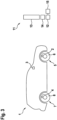
- a motor vehicle 1 is shown schematically.
- the motor vehicle 1 has a first RFID device 2.
- Identification information is stored on the first RFID device 2.
- the identification information is provided for identifying the motor vehicle 1.
- the motor vehicle 1 also has a communication device 3.
- the communication device 3 is provided for carrying out electronic payment transactions.
- the communication device 3 is part of the motor vehicle 1.
- a Figure 1 A motor vehicle driver (not shown) or another vehicle passenger can also carry the communication device 3 in the form of a smartphone.
- the motor vehicle 1 has a second RFID device 4.
- the second RFID device 4 is arranged on the motor vehicle 1. Further identification information that can be assigned to the motor vehicle 1 is stored on the second RFID device 4.
- the motor vehicle 1 has in particular a wheel 5 with a tire 6.
- the first RFID device 2 is arranged in particular on or in the tire 6.
- the motor vehicle 1 has, for example, another wheel 7 with another tire 8, wherein according to the Figure 1 In the schematically illustrated embodiment, the second RFID device 4 is arranged on or in the further tire 8.
- a tire 6 is shown schematically.
- the tire 6 has a first RFID device 2.
- the tire 6 is shown in a radial sectional view and is rotatable about a rotation axis 9 in a circumferential direction 10.
- a system 11 for blocking a path of a motor vehicle 1 is shown schematically.
- the system 11 has a first detection device 12.
- the first detection device 12 is provided for exchanging radio signals with a first RFID device 2 and/or with a second RFID device 4 and/or with a communication device 3.
- the first detection device 12 is also provided in particular for exchanging radio signals with a second RFID device 4.
- the system 11 has a barrier device 13.
- the barrier device 13 is intended to block a path of the motor vehicle 1.
- the system 11 further comprises an evaluation device 14, wherein the evaluation device 14 is provided for exchanging signals with the first detection device 12 and/or with a second detection device 15.
- the evaluation device 14 is connected to the barrier device 13 in such a way that, depending on a signal from the evaluation device 14, the barrier device 13 can be controlled in such a way that the blocking of the path of the motor vehicle 1 can be lifted or carried out.
Landscapes
- Business, Economics & Management (AREA)
- Finance (AREA)
- Physics & Mathematics (AREA)
- General Physics & Mathematics (AREA)
- Arrangements For Transmission Of Measured Signals (AREA)
Description
- Die vorliegende Erfindung bezieht sich auf ein Verfahren zur Bestimmung einer Zeitdifferenz nach Anspruch 1.
- Die Erfindung geht aus von einem Verfahren zur Bestimmung einer Zeitdifferenz.
- Aus dem Stand der Technik sind Verfahren zur Bestimmung von Zeitdifferenzen bekannt. Dabei ist es aus dem Stand der Technik insbesondere bekannt, solche Zeitdifferenzen zu bestimmen, die beispielsweise zwischen einem Einfahrtszeitpunkt und einem Ausfahrtszeitpunkt eines Kraftfahrzeuges in einem Parkhaus liegen können.
- Dabei ist es aus dem Stand der Technik auch bekannt, dass zu einem Verlassen eines Parkhauses die Entrichtung eines Geldbetrages, der im Zusammenhang der Zeitdifferenz steht, vorgenommen werden muss. Insbesondere die Entrichtung des Geldbetrages ist zumeist mit einem erhöhten Aufwand verbunden.
- Die
US 5 414 624 A offenbart ein solches Verfahren. - Die
WO 2018/179171 A1 offenbart ein ähnliches Vorgehen im Kontext einer Mauterfassung, in welchem aber keine Zeitdifferenz bestimmt wird. - Aus der
US 2017/061705 A1 ist ein Parkzeitbestimmungsverfahren auf offener Straße bekannt. - Die
DE 10 2017 216265 A1 beschreibt Fahrzeugreifen mit integrierten RFID Transpondern. - Der Erfindung liegt daher die Aufgabe zugrunde, ein verbessertes Verfahren zur Bestimmung einer Zeitdifferenz bereitzustellen, mittels dem insbesondere die Entrichtung eines Geldbetrages leichter und aufwandsärmer gestaltet werden kann.
- Gelöst wird die gestellte Aufgabe dadurch, dass das Verfahren folgende Schritte aufweist:
- a. Bereitstellen eines Kraftfahrzeugs, wobei das Kraftfahrzeug eine erste RFID-Vorrichtung aufweist, wobei auf der ersten RFID-Vorrichtung eine Identifikations-Information gespeichert und die Identifikations-Information zur Identifizierung des Kraftfahrzeugs vorgesehen ist und dem Kraftfahrzeug zugeordnet werden kann
- b. Bereitstellen einer Kommunikationsvorrichtung, wobei die Kommunikationsvorrichtung zu einer Durchführung eines elektronischen Zahlungsverkehrs vorgesehen ist;
- c. Bereitstellen einer ersten Erfassungsvorrichtung, wobei die erste Erfassungsvorrichtung zu einem Austausch von Funksignalen mit der ersten RFID-Vorrichtung vorgesehen ist und wobei die erste Erfassungsvorrichtung zu einem Austausch von Funksignalen mit der Kommunikationsvorrichtung vorgesehen ist;
- d. Austauschen eines Funksignals zwischen der ersten RFID-Vorrichtung und der ersten Erfassungsvorrichtung zu einem Startzeitpunkt;
- e. Austauschen eines Funksignals zwischen der ersten RFID-Vorrichtung und der ersten Erfassungsvorrichtung zu einem Endzeitpunkt;
- f. Bestimmen einer Zeitdifferenz zwischen dem Startzeitpunkt und dem Endzeitpunkt. Bei einer Zeitdifferenz handelt es sich beispielsweise um eine Zeitdauer oder um eine Zeitspanne.
- Die erste RFID-Vorrichtung ist insbesondere in einem Reifen des Kraftfahrzeugs oder an einem Reifen des Kraftfahrzeugs angeordnet.
- RFID bedeutet Radio Frequency Identification, also Identifikation unter Nutzung elektromagnetischer Wellen.
- Durch den erfindungsgemäßen Umstand, wonach das Verfahren zur Bestimmung einer Zeitdifferenz die erfindungsgemäßen Schritte a bis f aufweist, wird ein Verfahren ermöglicht, das vollständig automatisiert durchgeführt werden kann. Dadurch, dass das Verfahren vollständig automatisiert durchgeführt werden kann, kann das Verfahren selbst schneller, einfacher und weniger fehleranfällig durchgeführt werden.
- Somit wird ein verbessertes Verfahren bereitgestellt.
- Diese Offenbarung betrifft ferner ein Kraftfahrzeug, aufweisend eine erste RFID-Vorrichtung, wobei auf der ersten RFID-Vorrichtung eine Identifikation-Information gespeichert ist und die Identifikations-Information zur Identifizierung des Kraftfahrzeugs vorgesehen ist, und insbesondere aufweisend eine Kommunikationsvorrichtung, wobei die Kommunikationsvorrichtung zu einer Durchführung eines elektronischen Zahlungsverkehrs vorgesehen ist.
- Bei einer Kommunikationsvorrichtung handelt es sich um ein Smartphone, mittels dessen auf elektromagnetischem Wege ein Austausch von Signalen und ein Austausch von solchen Informationen vorgenommen wird, die der Ermöglichung eines elektronischen Zahlungsverkehrs dienen.
- Insbesondere kann das Kraftfahrzeug die Kommunikationsvorrichtung aufweisen oder der Fahrzeugführer des Kraftfahrzeugs weist eine Kommunikationsvorrichtung auf oder führt eine Kommunikationsvorrichtung mit sich.
- Diese Offenbarung betrifft ferner einen Reifen, aufweisend eine erste RFID-Vorrichtung, wobei auf der ersten RFID-Vorrichtung eine einem Kraftfahrzeug zuordnungsfähige Identifikations-Information gespeichert ist, und/oder aufweisend eine zweite RFID-Vorrichtung, wobei auf der zweiten RFID-Vorrichtung eine weitere dem Kraftfahrzeug zuordnungsfähige Identifikation-Information gespeichert ist.
- Bei dem Reifen handelt es sich insbesondere um einen PKW-Reifen oder um einen LKW-Reifen.
- Das Kraftfahrzeug weist insbesondere den obengenannten Reifen auf.
- Diese Offenbarung betrifft schließlich ein System zur Sperrung eines Weges eines Kraftfahrzeugs, aufweisend eine erste Erfassungsvorrichtung, wobei die erste Erfassungsvorrichtung zu einem Austausch von Funksignalen mit einer ersten RFID-Vorrichtung und/oder mit einer zweiten RFID-Vorrichtung und/oder mit einer Kommunikationsvorrichtung vorgesehen ist. Das System kann beispielsweise auf einem Parkplatz oder in einem Parkhaus oder in einer Garage angewendet werden.
- Gemäß der Erfindung weist das Verfahren folgende weitere Schritte auf
- g. Eindeutiges Zuordnen einer Information über einen Geldbetrag zu der bestimmten Zeitdifferenz;
- h. Austauschen eines Funksignals zwischen der Kommunikationsvorrichtung und der ersten Erfassungsvorrichtung zur Übermittlung und Zahlung eines Geldbetrages.
- Gemäß der Erfindung ist das Verfahren durch die weiteren Schritte gekennzeichnet:
- i. Bereitstellen einer Schrankenvorrichtung, wobei die Schrankenvorrichtung zur Sperrung eines Weges des Kraftfahrzeugs vorgesehen ist;
- j. Bereitstellen einer Auswertevorrichtung, wobei die Auswertevorrichtung zu einem Austausch von Signalen mit der ersten Erfassungsvorrichtung vorgesehen ist und wobei die Auswertevorrichtung mit der Schrankenvorrichtung derart verbunden ist, dass in Abhängigkeit eines Signals der Auswertevorrichtung die Schrankenvorrichtung derart gesteuert werden kann, dass die Sperrung des Weges des Kraftfahrzeugs aufgehoben oder vorgenommen werden kann;
- k. Austauschen eines Signals zwischen der Auswertevorrichtung und der ersten Erfassungsvorrichtung;
- 1. Öffnen der Schrankenvorrichtung in Abhängigkeit des Austauschs des Signals zwischen der Auswertevorrichtung und der ersten Erfassungsvorrichtung.
- Dabei wird die Schrankenvorrichtung insbesondere in Abhängigkeit des Austauschs des Signals zwischen der Auswertevorrichtung und der ersten Erfassungsvorrichtung geöffnet, wenn die Schrankenvorrichtung zuvor geschlossen ist. Für den Fall, wonach die Schrankenvorrichtung schon offen ist, wird der Zustand nicht verändert und die Schrankenvorrichtung im offenen Zustand belassen.
- Die Auswertevorrichtung kann beispielsweise zu einem Austausch von Funksignalen mit der ersten Erfassungsvorrichtung eingerichtet sein.
- Die Auswertevorrichtung und die erste Erfassungsvorrichtung können alternativ oder zusätzlich auch über ein Übertragungsmittel, beispielswiese einem Kabel, miteinander verbunden sein. Über das Übertragungsmittel können beispielsweise elektrische Signale übertragen werden.
- Die Auswertevorrichtung kann beispielsweise zu einem Austausch von Funksignalen mit der Schrankenvorrichtung eingerichtet sein.
- Die Auswertevorrichtung und die Schrankenvorrichtung können alternativ oder zusätzlich auch über ein Übertragungsmittel, beispielswiese einem Kabel, miteinander verbunden sein. Über das Übertragungsmittel können beispielsweise elektrische Signale übertragen werden.
- Gemäß der Erfindung ist das Verfahren durch die folgenden weiteren Schritte gekennzeichnet:
- Bereitstellen einer zweiten RFID-Vorrichtung, wobei die zweite RFID-Vorrichtung in einem Reifen des Kraftfahrzeugs angeordnet ist oder an einem Reifen des Kraftfahrzeugs angeordnet ist, wobei auf der zweiten RFID-Vorrichtung eine weitere Identifikations-Information gespeichert ist und die weitere Identifikations-Information zur Identifizierung des Kraftfahrzeugs vorgesehen ist und dem Kraftfahrzeug zugeordnet werden kann und wobei die erste Erfassungsvorrichtung zu einem Austausch von Funksignalen mit der ersten RFID-Vorrichtung und mit der zweiten RFID-Vorrichtung und mit der Kommunikationsvorrichtung vorgesehen ist;
- wobei nach dem Austausch eines Funksignals zwischen der ersten RFID-Vorrichtung und der ersten Erfassungsvorrichtung zu einem Startzeitpunkt ein Funksignal zwischen der zweiten RFID-Vorrichtung und der ersten Erfassungsvorrichtung zu einem ersten Kontrollzeitpunkt ausgetauscht wird, wobei der erste Kontrollzeitpunkt zeitlich später als der Startzeitpunkt liegt;
- wobei nach dem Austausch eines Funksignals zwischen der ersten RFID-Vorrichtung und der ersten Erfassungsvorrichtung zu einem Endzeitpunkt ein Funksignal zwischen der zweiten RFID-Vorrichtung und der ersten Erfassungsvorrichtung zu einem zweiten Kontrollzeitpunkt ausgetauscht wird, wobei der zweite Kontrollzeitpunkt zeitlich später als der Endzeitpunkt liegt;
- wobei die Zeitdifferenz zwischen dem Startzeitpunkt und dem Endzeitpunkt in Abhängigkeiten des Kontrollzeitpunktes und des zweiten Kontrollzeitpunktes bestimmt wird.
- Durch den erfindungsgemäßen Umstand, wonach das Verfahren die vorgenannten Schritte aufweist, kann die Zuverlässigkeit der Bestimmung einer Zeitdifferenz erhöht werden.
- Bei dem Reifen, in dem oder an dem die zweite RFID-Vorrichtung angeordnet ist, kann es sich gemäß sämtlicher Ausführungsformen um denselben oder um einen anderen Reifen handeln, als wie um den Reifen, in dem oder an dem die erste RFID-Vorrichtung angeordnet sein kann.
- Gemäß einer Ausgestaltung eines Kraftfahrzeuges welches im erfinderischen Verfahren bereitgestellt wird ist also eine zweite RFID-Vorrichtung an dem Kraftfahrzeug angeordnet. Dabei ist auf der zweiten RFID-Vorrichtung eine weitere dem Kraftfahrzeug zuordnungsfähige Identifikations-Information gespeichert. Die weitere Identifikations-Information, die auf der zweiten RFID-Vorrichtung gespeichert ist, ist von der Identifikations-Information, die auf der ersten RFID-Vorrichtung gespeichert ist, insbesondere verschieden und unterscheidbar. Mittels der ersten Erfassungsvorrichtung können die Identifikations-Information, die auf der ersten RFID-Vorrichtung gespeichert ist, und die weitere Identifikations-Information, die auf der zweiten RFID-Vorrichtung gespeichert ist, erfasst werden. Mittels der Auswertevorrichtung können die Identifikations-Information, die auf der ersten RFID-Vorrichtung gespeichert ist, und die weitere Identifikations-Information, die auf der zweiten RFID-Vorrichtung gespeichert ist, miteinander verglichen und dieser Vergleich ausgewertet werden. Dieser Vergleich und die Auswertung werden mittels einer Auswertevorrichtung insbesondere bei einer Einfahrt in ein Parkhaus und bei einer Ausfahrt aus einem Parkhaus durchgeführt, um beispielsweise eine genaue Zeitspanne zu bestimmen, während der das Kraftfahrzeug innerhalb des Parkhauses gewesen ist.
- Das Kraftfahrzeug weist ein Rad mit einem Reifen auf. Dabei kann die erste RFID-Vorrichtung in oder an dem Reifen angeordnet sein.
- Gemäß einer nächsten Ausgestalungsform des Kraftfahrzeuges weist das Kraftfahrzeug ein Rad mit einem Reifen auf, wobei die erste RFID-Vorrichtung und die zweite RFID-Vorrichtung in oder an dem Reifen angeordnet sind, oder, dass das Kraftfahrzeug ein Rad mit einem Reifen aufweist, wobei die erste RFID-Vorrichtung in oder an dem Reifen angeordnet ist, und das Kraftfahrzeug ein weiteres Rad mit einem weiteren Reifen ausweist, wobei die zweite RFID-Vorrichtung in oder an dem weiteren Reifen angeordnet ist.
- Gemäß einer nächsten vorzugsweisen Ausgestaltungsform des Kraftfahrzeuges handelt es sich bei der Kommunikationsvorrichtung um ein Smartphone oder eine NFC-Vorrichtung. NFC bedeutet Near Field Communication.
- Gemäß einer nächsten vorzugsweisen Ausgestaltungsform weist das System eine zweite Erfassungsvorrichtung auf, wobei die zweite Erfassungsvorrichtung zu einem Austausch von Funksignalen mit einer ersten RFID-Vorrichtung und/oder mit einer zweiten RFID-Vorrichtung und/oder mit einer Kommunikationsvorrichtung vorgesehen ist.
- Mittels der zweiten Erfassungsvorrichtung können die Identifikations-Information, die auf der ersten RFID-Vorrichtung gespeichert ist, und die weitere Identifikations-Information, die auf der zweiten RFID-Vorrichtung gespeichert ist, erfasst werden.
- Gemäß einer nächsten vorzugsweisen Ausgestaltungsform des Systems weist das System eine Schrankenvorrichtung auf, wobei die Schrankenvorrichtung zur Sperrung eines Weges eines Kraftfahrzeuges vorgesehen ist, und wobei das System eine Auswertevorrichtung aufweist, wobei die Auswertevorrichtung zu einem Austausch von Signalen mit der ersten Erfassungsvorrichtung vorgesehen ist und wobei die Auswertevorrichtung mit der Schrankenvorrichtung derart verbunden ist, dass in Abhängigkeit eines Signals der Auswertevorrichtung die Schrankenvorrichtung derart gesteuert werden kann, dass die Sperrung des Weges des Kraftfahrzeugs aufgehoben und vorgenommen werden kann.
- Gemäß einer nächsten vorzugsweisen Ausgestaltungsform des Systems weist das System eine Schrankenvorrichtung auf, wobei die Schrankenvorrichtung zur Sperrung eines Weges eines Kraftfahrzeugs vorgesehen ist, und wobei das System eine Auswertevorrichtung aufweist, wobei die Auswertevorrichtung zu einem Austausch von Signalen mit der ersten Erfassungsvorrichtung und/oder mit der zweiten Erfassungsvorrichtung vorgesehen und wobei die Auswertevorrichtung mit der Schrankenvorrichtung derart verbunden ist, dass in Abhängigkeit eines Signals der Auswertevorrichtung die Schrankenvorrichtung derart gesteuert werden kann, dass die Sperrung des Weges des Kraftfahrzeuges aufgehoben oder vorgenommen werden kann. Die Auswertevorrichtung und die erste Erfassungsvorrichtung beziehungsweise die Auswertevorrichtung und die zweite Erfassungsvorrichtung können alternativ oder zusätzlich auch über ein Übertragungsmittel, beispielswiese einem Kabel, miteinander verbunden sein. Über das Übertragungsmittel können beispielsweise elektrische Signale übertragen werden.
- Die Auswertevorrichtung und die erste Erfassungsvorrichtung beziehungsweise die Auswertevorrichtung und die zweite Erfassungsvorrichtung können alternativ oder zusätzlich über Funksignale miteinander verbindbar sein.
- Weitere Merkmale, Vorteile und Einzelheiten, auf die die Erfindung in ihrem Umfang aber nicht beschränkt ist, werden nun anhand der Zeichnungen näher beschrieben.
- Es zeigt:
-
Fig. 1 : Eine schematische Darstellung eines Kraftfahrzeugs, -
Fig. 2 : eine schematische Darstellung eines Reifens; -
Fig. 3 : eine schematische Darstellung eines Systems - In der
Figur 1 ist ein Kraftfahrzeug 1 schematisch dargestellt. Das Kraftfahrzeug 1 weist eine erste RFID-Vorrichtung 2 auf. Auf der ersten RFID-Vorrichtung 2 ist eine Identifikations-Information gespeichert. Die Identifikations-Information ist zur Identifizierung des Kraftfahrzeugs 1 vorgesehen. Das Kraftfahrzeug 1 weist ferner eine Kommunikationsvorrichtung 3 auf. Die Kommunikationsvorrichtung 3 ist zu einer Durchführung eines elektronischen Zahlungsverkehrs vorgesehen. Gemäß der in derFigur 1 dargestellten Ausführungsform ist die Kommunikationsvorrichtung 3 Bestandteil des Kraftfahrzeugs 1. Gemäß einer anderen Ausführungsform kann ein in derFigur 1 nicht dargestellter Kraftfahrzeugführer oder ein anderer Fahrzeuggast die Kommunikationsvorrichtung 3 auch in Form eines Smartphones bei sich führen. Insbesondere weist das Kraftfahrzeug 1 eine zweite RFID-Vorrichtung 4 auf. Wobei die zweite RFID-Vorrichtung 4 an dem Kraftfahrzeug 1 angeordnet ist. Auf der zweiten RFID-Vorrichtung 4 ist eine weitere dem Kraftfahrzeug 1 zuordnungsfähige Identifikations-Information gespeichert. - Ferner weist das Kraftfahrzeug 1 insbesondere ein Rad 5 mit einem Reifen 6 auf. Dabei ist gemäß der in der
Figur 1 schematisch dargestellten Ausführungsform die erste RFID-Vorrichtung 2 insbesondere an oder in dem Reifen 6 angeordnet. - Ferner weist das Kraftfahrzeug 1 beispielsweise ein weiteres Rad 7 mit einem weiteren Reifen 8 auf, wobei gemäß der in der
Figur 1 schematisch dargestellten Ausführungsform die zweite RFID-Vorrichtung 4 an oder in dem weiteren Reifen 8 angeordnet ist. - In der
Figur 2 ist ein Reifen 6 schematisch dargestellt. Der Reifen 6 weist eine erste RFID-Vorrichtung 2 auf. Der Reifen 6 ist in Radialschnittansicht dargestellt und ist um eine Rotationsachse 9 in eine Umfangsrichtung 10 rotierbar. - In der
Figur 3 ist ein System 11 zur Sperrung eines Weges eines Kraftfahrzeugs 1 schematisch dargestellt. Das System 11 weist eine erste Erfassungsvorrichtung 12 auf. Die erste Erfassungsvorrichtung 12 ist zu einem Austausch von Funksignalen mit einer ersten RFID-Vorrichtung 2 und/oder mit einer zweiten RFID-Vorrichtung 4 und/oder mit einer Kommunikationsvorrichtung 3 vorgesehen. Die erste Erfassungsvorrichtung 12 ist insbesondere auch zu einem Austausch von Funksignalen mit einer zweiten RFID-Vorrichtung 4 vorgesehen. - Beispielsweise weist das System 11 eine Schrankenvorrichtung 13 auf. Die Schrankenvorrichtung 13 ist zur Sperrung eines Weges des Kraftfahrzeugs 1 vorgesehen.
- Das System 11 weist ferner eine Auswertevorrichtung 14 auf, wobei die Auswertevorrichtung 14 zu einem Austausch von Signalen mit der ersten Erfassungsvorrichtung 12 und/oder mit einer zweiten Erfassungsvorrichtung 15 vorgesehen ist. Dabei ist die Auswertevorrichtung 14 mit der Schrankenvorrichtung 13 derart verbunden, dass in Abhängigkeit eines Signals der Auswertevorrichtung 14 die Schrankenvorrichtung 13 derart gesteuert werden kann, dass die Sperrung des Weges des Kraftfahrzeuges 1 aufgehoben oder vorgenommen werden kann.
-
- 1
- Kraftfahrzeug
- 2
- Erste RFID-Vorrichtung
- 3
- Kommunikationsvorrichtung
- 4
- Zweite RFID-Vorrichtung
- 5
- Rad
- 6
- Reifen
- 7
- Weiteres Rad
- 8
- Weiterer Reifen
- 9
- Rotationsachse
- 10
- Umlaufrichtung
- 11
- System
- 12
- Erste Erfassungsvorrichtung
- 13
- Schrankenvorrichtung
- 14
- Auswertevorrichtung
- 15
- Zweite Erfassungsvorrichtung
Claims (1)
- Verfahren zur Bestimmung einer Zeitdifferenz, aufweisend die Schritte:- a) Bereitstellen eines Kraftfahrzeugs (1), wobei das Kraftfahrzeug (1) eine erste RFID-Vorrichtung (2) aufweist, wobei auf der ersten RFID-Vorrichtung (2) eine Identifikations-Information gespeichert ist und die Identifikations-Information zur Identifizierung des Kraftfahrzeugs (1) vorgesehen ist und dem Kraftfahrzeug (1) zugeordnet werden kann,- b) Bereitstellen einer Kommunikationsvorrichtung (3), wobei die Kommunikationsvorrichtung (3) zu einer Durchführung eines elektronischen Zahlungsverkehrs vorgesehen ist, wobei es sich bei der Kommunikationsvorrichtung um ein Smartphone handelt;- c) Bereitstellen einer ersten Erfassungsvorrichtung (12), wobei die erste Erfassungsvorrichtung (12) zu einem Austausch von Funksignalen mit der ersten RFID-Vorrichtung (2) vorgesehen ist und wobei die erste Erfassungsvorrichtung (12) zu einem Austausch von Funksignalen mit der Kommunikationsvorrichtung (3) vorgesehen ist;- d) Austauschen eines Funksignals zwischen der ersten RFID-Vorrichtung (2) und der ersten Erfassungsvorrichtung (12) zu einem Startzeitpunkt;- e) Austauschen eines Funksignals zwischen der ersten RFID-Vorrichtung (2) und der ersten Erfassungsvorrichtung (12) zu einem Endzeitpunkt;- f) Bestimmen einer Zeitdifferenz zwischen dem Startzeitpunkt und dem Endzeitpunkt.- g) Eindeutiges Zuordnen einer Information über einen Geldbetrag zu der bestimmten Zeitdifferenz;- h) Austauschen eines Funksignals zwischen der Kommunikationsvorrichtung (3) und der ersten Erfassungsvorrichtung (12) zur Übermittlung einer Zahlung des Geldbetrages;- i) Bereitstellen einer Schrankenvorrichtung (13), wobei die Schrankenvorrichtung (13) zur Sperrung eines Weges des Kraftfahrzeugs (1) vorgesehen ist;- j) Bereitstellen einer Auswertevorrichtung (14), wobei die Auswertevorrichtung (14) zu einem Austausch von Signalen mit der ersten Erfassungsvorrichtung (12) vorgesehen ist und wobei die Auswertevorrichtung (14) mit der Schrankenvorrichtung (13) derart verbunden ist, dass in Abhängigkeit eines Signals der Auswertevorrichtung (14) die Schrankenvorrichtung (13) derart gesteuert werden kann, dass die Sperrung des Weges des Kraftfahrzeugs (1) aufgehoben oder vorgenommen werden kann;- k) Austauschen eines Signals zwischen der Auswertevorrichtung (14) und der ersten Erfassungsvorrichtung (12);- l) Öffnen der Schrankenvorrichtung (13) in Abhängigkeit des Austauschs des Signals zwischen der Auswertevorrichtung (14) und der ersten Erfassungsvorrichtung (12);- Bereitstellen einer zweiten RFID-Vorrichtung (4), wobei die zweite RFID-Vorrichtung (4) in einem Reifen (6, 8) des Kraftfahrzeugs (1) angeordnet ist oder an einem Reifen (6, 8) des Kraftfahrzeugs (1) angeordnet ist, wobei auf der zweiten RFID-Vorrichtung (4) eine weitere Identifikations-Information gespeichert ist und die weitere Identifikations-Information zur Identifizierung des Kraftfahrzeugs (1) vorgesehen ist und dem Kraftfahrzeug (1) zugeordnet werden kann und wobei die erste Erfassungsvorrichtung (12) zu einem Austausch von Funksignalen mit der ersten RFID-Vorrichtung (2) und mit der zweiten RFID-Vorrichtung (4) und mit der Kommunikationsvorrichtung (3) vorgesehen ist,- wobei nach dem Austausch eines Funksignals zwischen der ersten RFID-Vorrichtung (2) und der ersten Erfassungsvorrichtung (12) zu einem Startzeitpunkt ein Funksignal zwischen der zweiten RFID-Vorrichtung (4) und der ersten Erfassungsvorrichtung (12) zu einem ersten Kontrollzeitpunkt ausgetauscht wird, wobei der erste Kontrollzeitpunkt zeitlich später als der Startzeitpunkt liegt;- wobei nach dem Austausch eines Funksignals zwischen der ersten RFID-Vorrichtung (2) und der ersten Erfassungsvorrichtung (12) zu einem Endzeitpunkt ein Funksignal zwischen der zweiten RFID-Vorrichtung (4) und der ersten Erfassungsvorrichtung (12) zu einem zweiten Kontrollzeitpunkt ausgetauscht wird, wobei der zweite Kontrollzeitpunkt zeitlich später als der Endzeitpunkt liegt,- wobei die Zeitdifferenz zwischen dem Startzeitpunkt und dem Endzeitpunkt in Abhängigkeit des ersten Kontrollzeitpunktes und des zweiten Kontrollzeitpunktes bestimmt wird.
Applications Claiming Priority (2)
| Application Number | Priority Date | Filing Date | Title |
|---|---|---|---|
| DE102019203872.7A DE102019203872A1 (de) | 2019-03-21 | 2019-03-21 | Verfahren zur Bestimmung einer Zeitdifferenz |
| PCT/EP2020/051962 WO2020187470A1 (de) | 2019-03-21 | 2020-01-28 | Verfahren zur bestimmung einer zeitdifferenz |
Publications (2)
| Publication Number | Publication Date |
|---|---|
| EP3942534A1 EP3942534A1 (de) | 2022-01-26 |
| EP3942534B1 true EP3942534B1 (de) | 2024-05-22 |
Family
ID=69400546
Family Applications (1)
| Application Number | Title | Priority Date | Filing Date |
|---|---|---|---|
| EP20702765.7A Active EP3942534B1 (de) | 2019-03-21 | 2020-01-28 | Verfahren zur bestimmung einer zeitdifferenz |
Country Status (3)
| Country | Link |
|---|---|
| EP (1) | EP3942534B1 (de) |
| DE (1) | DE102019203872A1 (de) |
| WO (1) | WO2020187470A1 (de) |
Family Cites Families (4)
| Publication number | Priority date | Publication date | Assignee | Title |
|---|---|---|---|---|
| US5414624A (en) * | 1993-11-08 | 1995-05-09 | Avid Systems Corporation | Automated vehicle parking system |
| US20170061705A1 (en) * | 2015-08-25 | 2017-03-02 | Agustin Ulloa | Parking meter payment system |
| WO2018179171A1 (ja) * | 2017-03-29 | 2018-10-04 | 三菱重工機械システム株式会社 | 課金システム、課金方法及びプログラム |
| DE102017216265A1 (de) * | 2017-09-14 | 2019-03-14 | Continental Reifen Deutschland Gmbh | Identifikationseinheit sowie Reifen mit einer derartigen Identifikationseinheit |
-
2019
- 2019-03-21 DE DE102019203872.7A patent/DE102019203872A1/de not_active Withdrawn
-
2020
- 2020-01-28 EP EP20702765.7A patent/EP3942534B1/de active Active
- 2020-01-28 WO PCT/EP2020/051962 patent/WO2020187470A1/de not_active Ceased
Also Published As
| Publication number | Publication date |
|---|---|
| DE102019203872A1 (de) | 2020-09-24 |
| EP3942534A1 (de) | 2022-01-26 |
| WO2020187470A1 (de) | 2020-09-24 |
Similar Documents
| Publication | Publication Date | Title |
|---|---|---|
| DE102008021030B4 (de) | Verfahren zum Betreiben eines Fahrzeugs sowie entsprechende Vorrichtung und entsprechendes Fahrzeug | |
| EP3051502A1 (de) | Parkraum-zufahrtskontrollsystem sowie verfahren zur kontrolle der zufahrt in einen parkraum | |
| DE102013006070A1 (de) | Verfahren und Vorrichtung zur Übermittlung fahrzeugspezifischer Informationen an ein Endgerät eines Nutzers durch Mittel der drahtlosen Kommunikation | |
| DE102007051961A1 (de) | Einrichtung zum Überwachen von sich in einem ausgezeichneten Bereich, insbesondere einem Werksgelände oder einem Parkhaus befindlichen Fahrzeugen | |
| DE202014002729U1 (de) | Einrichtung zur Erfassung, Klassifikation und Verwiegung von Kraftfahrzeugen auf Straßen im fließenden Verkehr | |
| DE102019002302A1 (de) | Verfahren zur Positionsbestimung eines Fahrzeugs in einem vorgegebenen Ladeareal und Positionsbestimmungsanordnung | |
| EP3511920A1 (de) | Parkassistenzsystem mit entfernter konfiguration eines lokalen neuronalen netzes | |
| EP3942534B1 (de) | Verfahren zur bestimmung einer zeitdifferenz | |
| EP3355249B1 (de) | Verfahren zum zuordnen eines fahrzeugs zu einem parkplatz, datenverarbeitungsanlage und fahrzeug | |
| EP1361488B1 (de) | Verfahren und Vorrichtung zum automatischen Klassifizieren von mit Rädern ausgestatteten Fahrzeugen | |
| EP2261084A1 (de) | Verfahren und Steuergerät zur Lokalisierung einer Parklücke für ein Fahrzeug | |
| DE102007035737A1 (de) | Verfahren zum Überprüfen einer von einem Fahrzeug ausgesendeten Positionsnachricht des Fahrzeugs und Sende- und Empfangseinrichtung zur Verwendung in einem Fahrzeug | |
| EP3032501A1 (de) | Verfahren zum Betreiben eines ID-basierten Zugangskontrollsystems | |
| DE102017215559A1 (de) | Verfahren und Vorrichtung zur Risikobewertung einer Fahrt mit einem Straßenfahrzeug | |
| DE102016011856A1 (de) | Verfahren zur Auswahl eines Fahrzeugs aus einer Menge möglicher Fahrzeuge per Fernzugriff | |
| DE102014018190A1 (de) | Zugangskontrollsystem für einen Verkehrsraum, Parkraummanagementsystem und Zugangskontrollverfahren für einen Verkehrsraum | |
| EP3969846B1 (de) | Verfahren zum validieren einer kartenaktualität | |
| DE102022202741A1 (de) | Verfahren zum Ausführen einer zumindest teilautomatisierten Fahrfunktion | |
| DE102022113811A1 (de) | Verfahren zum Betreiben eines automatisierten Kraftfahrzeugs zum Auswählen einer Durchfahrtsspur einer Mautstation, Computerprogramm, Datenverarbeitungsvorrichtung und automatisiertes Kraftfahrzeug | |
| DE102019219384A1 (de) | Verfahren zum Navigieren von Fahrzeugen | |
| DE102020212188A1 (de) | Verfahren und System zum Übermitteln von Daten | |
| DE102017221167B4 (de) | Verfahren, Vorrichtung, Computerprogramm und Computerprogrammprodukt zum Parken eines Fahrzeugs | |
| EP4264973B1 (de) | Verfahren und vorrichtung zur zuordnung einer identifizierungsinformation und identifizierungsdaten zu einem fahrzeug | |
| EP4715782A1 (de) | Verfahren zur verkehrsüberwachung und verkehrsüberwachungssystem | |
| WO2012048859A1 (de) | Fahrzeugschlüssel mit einer elektronischen wegfahrsperre |
Legal Events
| Date | Code | Title | Description |
|---|---|---|---|
| STAA | Information on the status of an ep patent application or granted ep patent |
Free format text: STATUS: UNKNOWN |
|
| STAA | Information on the status of an ep patent application or granted ep patent |
Free format text: STATUS: THE INTERNATIONAL PUBLICATION HAS BEEN MADE |
|
| PUAI | Public reference made under article 153(3) epc to a published international application that has entered the european phase |
Free format text: ORIGINAL CODE: 0009012 |
|
| STAA | Information on the status of an ep patent application or granted ep patent |
Free format text: STATUS: REQUEST FOR EXAMINATION WAS MADE |
|
| 17P | Request for examination filed |
Effective date: 20211021 |
|
| AK | Designated contracting states |
Kind code of ref document: A1 Designated state(s): AL AT BE BG CH CY CZ DE DK EE ES FI FR GB GR HR HU IE IS IT LI LT LU LV MC MK MT NL NO PL PT RO RS SE SI SK SM TR |
|
| DAV | Request for validation of the european patent (deleted) | ||
| DAX | Request for extension of the european patent (deleted) | ||
| GRAP | Despatch of communication of intention to grant a patent |
Free format text: ORIGINAL CODE: EPIDOSNIGR1 |
|
| STAA | Information on the status of an ep patent application or granted ep patent |
Free format text: STATUS: GRANT OF PATENT IS INTENDED |
|
| INTG | Intention to grant announced |
Effective date: 20240209 |
|
| RAP3 | Party data changed (applicant data changed or rights of an application transferred) |
Owner name: CONTINENTAL AUTOMOTIVE ROMANIA SRL Owner name: CONTINENTAL REIFEN DEUTSCHLAND GMBH |
|
| GRAS | Grant fee paid |
Free format text: ORIGINAL CODE: EPIDOSNIGR3 |
|
| P01 | Opt-out of the competence of the unified patent court (upc) registered |
Effective date: 20240308 |
|
| GRAA | (expected) grant |
Free format text: ORIGINAL CODE: 0009210 |
|
| STAA | Information on the status of an ep patent application or granted ep patent |
Free format text: STATUS: THE PATENT HAS BEEN GRANTED |
|
| AK | Designated contracting states |
Kind code of ref document: B1 Designated state(s): AL AT BE BG CH CY CZ DE DK EE ES FI FR GB GR HR HU IE IS IT LI LT LU LV MC MK MT NL NO PL PT RO RS SE SI SK SM TR |
|
| REG | Reference to a national code |
Ref country code: GB Ref legal event code: FG4D Free format text: NOT ENGLISH |
|
| REG | Reference to a national code |
Ref country code: CH Ref legal event code: EP |
|
| REG | Reference to a national code |
Ref country code: DE Ref legal event code: R096 Ref document number: 502020008060 Country of ref document: DE |
|
| REG | Reference to a national code |
Ref country code: IE Ref legal event code: FG4D Free format text: LANGUAGE OF EP DOCUMENT: GERMAN |
|
| REG | Reference to a national code |
Ref country code: LT Ref legal event code: MG9D |
|
| REG | Reference to a national code |
Ref country code: NL Ref legal event code: MP Effective date: 20240522 |
|
| PG25 | Lapsed in a contracting state [announced via postgrant information from national office to epo] |
Ref country code: IS Free format text: LAPSE BECAUSE OF FAILURE TO SUBMIT A TRANSLATION OF THE DESCRIPTION OR TO PAY THE FEE WITHIN THE PRESCRIBED TIME-LIMIT Effective date: 20240922 |
|
| PG25 | Lapsed in a contracting state [announced via postgrant information from national office to epo] |
Ref country code: BG Free format text: LAPSE BECAUSE OF FAILURE TO SUBMIT A TRANSLATION OF THE DESCRIPTION OR TO PAY THE FEE WITHIN THE PRESCRIBED TIME-LIMIT Effective date: 20240522 |
|
| PG25 | Lapsed in a contracting state [announced via postgrant information from national office to epo] |
Ref country code: FI Free format text: LAPSE BECAUSE OF FAILURE TO SUBMIT A TRANSLATION OF THE DESCRIPTION OR TO PAY THE FEE WITHIN THE PRESCRIBED TIME-LIMIT Effective date: 20240522 Ref country code: HR Free format text: LAPSE BECAUSE OF FAILURE TO SUBMIT A TRANSLATION OF THE DESCRIPTION OR TO PAY THE FEE WITHIN THE PRESCRIBED TIME-LIMIT Effective date: 20240522 |
|
| PG25 | Lapsed in a contracting state [announced via postgrant information from national office to epo] |
Ref country code: GR Free format text: LAPSE BECAUSE OF FAILURE TO SUBMIT A TRANSLATION OF THE DESCRIPTION OR TO PAY THE FEE WITHIN THE PRESCRIBED TIME-LIMIT Effective date: 20240823 |
|
| PG25 | Lapsed in a contracting state [announced via postgrant information from national office to epo] |
Ref country code: PT Free format text: LAPSE BECAUSE OF FAILURE TO SUBMIT A TRANSLATION OF THE DESCRIPTION OR TO PAY THE FEE WITHIN THE PRESCRIBED TIME-LIMIT Effective date: 20240923 |
|
| PG25 | Lapsed in a contracting state [announced via postgrant information from national office to epo] |
Ref country code: NL Free format text: LAPSE BECAUSE OF FAILURE TO SUBMIT A TRANSLATION OF THE DESCRIPTION OR TO PAY THE FEE WITHIN THE PRESCRIBED TIME-LIMIT Effective date: 20240522 |
|
| PG25 | Lapsed in a contracting state [announced via postgrant information from national office to epo] |
Ref country code: ES Free format text: LAPSE BECAUSE OF FAILURE TO SUBMIT A TRANSLATION OF THE DESCRIPTION OR TO PAY THE FEE WITHIN THE PRESCRIBED TIME-LIMIT Effective date: 20240522 |
|
| PG25 | Lapsed in a contracting state [announced via postgrant information from national office to epo] |
Ref country code: PL Free format text: LAPSE BECAUSE OF FAILURE TO SUBMIT A TRANSLATION OF THE DESCRIPTION OR TO PAY THE FEE WITHIN THE PRESCRIBED TIME-LIMIT Effective date: 20240522 |
|
| PG25 | Lapsed in a contracting state [announced via postgrant information from national office to epo] |
Ref country code: LV Free format text: LAPSE BECAUSE OF FAILURE TO SUBMIT A TRANSLATION OF THE DESCRIPTION OR TO PAY THE FEE WITHIN THE PRESCRIBED TIME-LIMIT Effective date: 20240522 |
|
| PG25 | Lapsed in a contracting state [announced via postgrant information from national office to epo] |
Ref country code: PT Free format text: LAPSE BECAUSE OF FAILURE TO SUBMIT A TRANSLATION OF THE DESCRIPTION OR TO PAY THE FEE WITHIN THE PRESCRIBED TIME-LIMIT Effective date: 20240923 Ref country code: PL Free format text: LAPSE BECAUSE OF FAILURE TO SUBMIT A TRANSLATION OF THE DESCRIPTION OR TO PAY THE FEE WITHIN THE PRESCRIBED TIME-LIMIT Effective date: 20240522 Ref country code: NO Free format text: LAPSE BECAUSE OF FAILURE TO SUBMIT A TRANSLATION OF THE DESCRIPTION OR TO PAY THE FEE WITHIN THE PRESCRIBED TIME-LIMIT Effective date: 20240822 Ref country code: NL Free format text: LAPSE BECAUSE OF FAILURE TO SUBMIT A TRANSLATION OF THE DESCRIPTION OR TO PAY THE FEE WITHIN THE PRESCRIBED TIME-LIMIT Effective date: 20240522 Ref country code: LV Free format text: LAPSE BECAUSE OF FAILURE TO SUBMIT A TRANSLATION OF THE DESCRIPTION OR TO PAY THE FEE WITHIN THE PRESCRIBED TIME-LIMIT Effective date: 20240522 Ref country code: IS Free format text: LAPSE BECAUSE OF FAILURE TO SUBMIT A TRANSLATION OF THE DESCRIPTION OR TO PAY THE FEE WITHIN THE PRESCRIBED TIME-LIMIT Effective date: 20240922 Ref country code: HR Free format text: LAPSE BECAUSE OF FAILURE TO SUBMIT A TRANSLATION OF THE DESCRIPTION OR TO PAY THE FEE WITHIN THE PRESCRIBED TIME-LIMIT Effective date: 20240522 Ref country code: GR Free format text: LAPSE BECAUSE OF FAILURE TO SUBMIT A TRANSLATION OF THE DESCRIPTION OR TO PAY THE FEE WITHIN THE PRESCRIBED TIME-LIMIT Effective date: 20240823 Ref country code: FI Free format text: LAPSE BECAUSE OF FAILURE TO SUBMIT A TRANSLATION OF THE DESCRIPTION OR TO PAY THE FEE WITHIN THE PRESCRIBED TIME-LIMIT Effective date: 20240522 Ref country code: ES Free format text: LAPSE BECAUSE OF FAILURE TO SUBMIT A TRANSLATION OF THE DESCRIPTION OR TO PAY THE FEE WITHIN THE PRESCRIBED TIME-LIMIT Effective date: 20240522 Ref country code: BG Free format text: LAPSE BECAUSE OF FAILURE TO SUBMIT A TRANSLATION OF THE DESCRIPTION OR TO PAY THE FEE WITHIN THE PRESCRIBED TIME-LIMIT Effective date: 20240522 Ref country code: RS Free format text: LAPSE BECAUSE OF FAILURE TO SUBMIT A TRANSLATION OF THE DESCRIPTION OR TO PAY THE FEE WITHIN THE PRESCRIBED TIME-LIMIT Effective date: 20240822 |
|
| PG25 | Lapsed in a contracting state [announced via postgrant information from national office to epo] |
Ref country code: DK Free format text: LAPSE BECAUSE OF FAILURE TO SUBMIT A TRANSLATION OF THE DESCRIPTION OR TO PAY THE FEE WITHIN THE PRESCRIBED TIME-LIMIT Effective date: 20240522 |
|
| PG25 | Lapsed in a contracting state [announced via postgrant information from national office to epo] |
Ref country code: EE Free format text: LAPSE BECAUSE OF FAILURE TO SUBMIT A TRANSLATION OF THE DESCRIPTION OR TO PAY THE FEE WITHIN THE PRESCRIBED TIME-LIMIT Effective date: 20240522 |
|
| PG25 | Lapsed in a contracting state [announced via postgrant information from national office to epo] |
Ref country code: CZ Free format text: LAPSE BECAUSE OF FAILURE TO SUBMIT A TRANSLATION OF THE DESCRIPTION OR TO PAY THE FEE WITHIN THE PRESCRIBED TIME-LIMIT Effective date: 20240522 |
|
| PG25 | Lapsed in a contracting state [announced via postgrant information from national office to epo] |
Ref country code: SK Free format text: LAPSE BECAUSE OF FAILURE TO SUBMIT A TRANSLATION OF THE DESCRIPTION OR TO PAY THE FEE WITHIN THE PRESCRIBED TIME-LIMIT Effective date: 20240522 Ref country code: RO Free format text: LAPSE BECAUSE OF FAILURE TO SUBMIT A TRANSLATION OF THE DESCRIPTION OR TO PAY THE FEE WITHIN THE PRESCRIBED TIME-LIMIT Effective date: 20240522 |
|
| PG25 | Lapsed in a contracting state [announced via postgrant information from national office to epo] |
Ref country code: SM Free format text: LAPSE BECAUSE OF FAILURE TO SUBMIT A TRANSLATION OF THE DESCRIPTION OR TO PAY THE FEE WITHIN THE PRESCRIBED TIME-LIMIT Effective date: 20240522 |
|
| PG25 | Lapsed in a contracting state [announced via postgrant information from national office to epo] |
Ref country code: SM Free format text: LAPSE BECAUSE OF FAILURE TO SUBMIT A TRANSLATION OF THE DESCRIPTION OR TO PAY THE FEE WITHIN THE PRESCRIBED TIME-LIMIT Effective date: 20240522 Ref country code: SK Free format text: LAPSE BECAUSE OF FAILURE TO SUBMIT A TRANSLATION OF THE DESCRIPTION OR TO PAY THE FEE WITHIN THE PRESCRIBED TIME-LIMIT Effective date: 20240522 Ref country code: RO Free format text: LAPSE BECAUSE OF FAILURE TO SUBMIT A TRANSLATION OF THE DESCRIPTION OR TO PAY THE FEE WITHIN THE PRESCRIBED TIME-LIMIT Effective date: 20240522 Ref country code: EE Free format text: LAPSE BECAUSE OF FAILURE TO SUBMIT A TRANSLATION OF THE DESCRIPTION OR TO PAY THE FEE WITHIN THE PRESCRIBED TIME-LIMIT Effective date: 20240522 Ref country code: DK Free format text: LAPSE BECAUSE OF FAILURE TO SUBMIT A TRANSLATION OF THE DESCRIPTION OR TO PAY THE FEE WITHIN THE PRESCRIBED TIME-LIMIT Effective date: 20240522 Ref country code: CZ Free format text: LAPSE BECAUSE OF FAILURE TO SUBMIT A TRANSLATION OF THE DESCRIPTION OR TO PAY THE FEE WITHIN THE PRESCRIBED TIME-LIMIT Effective date: 20240522 |
|
| PG25 | Lapsed in a contracting state [announced via postgrant information from national office to epo] |
Ref country code: IT Free format text: LAPSE BECAUSE OF FAILURE TO SUBMIT A TRANSLATION OF THE DESCRIPTION OR TO PAY THE FEE WITHIN THE PRESCRIBED TIME-LIMIT Effective date: 20240522 |
|
| REG | Reference to a national code |
Ref country code: DE Ref legal event code: R097 Ref document number: 502020008060 Country of ref document: DE |
|
| PLBE | No opposition filed within time limit |
Free format text: ORIGINAL CODE: 0009261 |
|
| STAA | Information on the status of an ep patent application or granted ep patent |
Free format text: STATUS: NO OPPOSITION FILED WITHIN TIME LIMIT |
|
| PG25 | Lapsed in a contracting state [announced via postgrant information from national office to epo] |
Ref country code: SI Free format text: LAPSE BECAUSE OF FAILURE TO SUBMIT A TRANSLATION OF THE DESCRIPTION OR TO PAY THE FEE WITHIN THE PRESCRIBED TIME-LIMIT Effective date: 20240522 |
|
| 26N | No opposition filed |
Effective date: 20250225 |
|
| REG | Reference to a national code |
Ref country code: CH Ref legal event code: PL |
|
| PG25 | Lapsed in a contracting state [announced via postgrant information from national office to epo] |
Ref country code: SE Free format text: LAPSE BECAUSE OF FAILURE TO SUBMIT A TRANSLATION OF THE DESCRIPTION OR TO PAY THE FEE WITHIN THE PRESCRIBED TIME-LIMIT Effective date: 20240522 |
|
| PG25 | Lapsed in a contracting state [announced via postgrant information from national office to epo] |
Ref country code: LU Free format text: LAPSE BECAUSE OF NON-PAYMENT OF DUE FEES Effective date: 20250128 Ref country code: MC Free format text: LAPSE BECAUSE OF FAILURE TO SUBMIT A TRANSLATION OF THE DESCRIPTION OR TO PAY THE FEE WITHIN THE PRESCRIBED TIME-LIMIT Effective date: 20240522 |
|
| GBPC | Gb: european patent ceased through non-payment of renewal fee |
Effective date: 20250128 |
|
| PG25 | Lapsed in a contracting state [announced via postgrant information from national office to epo] |
Ref country code: BE Free format text: LAPSE BECAUSE OF NON-PAYMENT OF DUE FEES Effective date: 20250131 Ref country code: GB Free format text: LAPSE BECAUSE OF NON-PAYMENT OF DUE FEES Effective date: 20250128 |
|
| PG25 | Lapsed in a contracting state [announced via postgrant information from national office to epo] |
Ref country code: FR Free format text: LAPSE BECAUSE OF NON-PAYMENT OF DUE FEES Effective date: 20250131 |
|
| PG25 | Lapsed in a contracting state [announced via postgrant information from national office to epo] |
Ref country code: CH Free format text: LAPSE BECAUSE OF NON-PAYMENT OF DUE FEES Effective date: 20250131 |
|
| REG | Reference to a national code |
Ref country code: BE Ref legal event code: MM Effective date: 20250131 |
|
| PG25 | Lapsed in a contracting state [announced via postgrant information from national office to epo] |
Ref country code: IE Free format text: LAPSE BECAUSE OF NON-PAYMENT OF DUE FEES Effective date: 20250128 |
|
| REG | Reference to a national code |
Ref country code: AT Ref legal event code: MM01 Ref document number: 1689396 Country of ref document: AT Kind code of ref document: T Effective date: 20250128 |
|
| PGFP | Annual fee paid to national office [announced via postgrant information from national office to epo] |
Ref country code: DE Payment date: 20260319 Year of fee payment: 7 |
|
| PG25 | Lapsed in a contracting state [announced via postgrant information from national office to epo] |
Ref country code: AT Free format text: LAPSE BECAUSE OF NON-PAYMENT OF DUE FEES Effective date: 20250128 |