EP3941866B1 - Gripper assembly, apparatus for recovering a layout from a sheet material and method for separating a layout from waste of a sheet material - Google Patents
Gripper assembly, apparatus for recovering a layout from a sheet material and method for separating a layout from waste of a sheet material Download PDFInfo
- Publication number
- EP3941866B1 EP3941866B1 EP20711503.1A EP20711503A EP3941866B1 EP 3941866 B1 EP3941866 B1 EP 3941866B1 EP 20711503 A EP20711503 A EP 20711503A EP 3941866 B1 EP3941866 B1 EP 3941866B1
- Authority
- EP
- European Patent Office
- Prior art keywords
- gripper
- sheet material
- vacuum
- layout
- blanks
- Prior art date
- Legal status (The legal status is an assumption and is not a legal conclusion. Google has not performed a legal analysis and makes no representation as to the accuracy of the status listed.)
- Active
Links
Images




Classifications
-
- B—PERFORMING OPERATIONS; TRANSPORTING
- B65—CONVEYING; PACKING; STORING; HANDLING THIN OR FILAMENTARY MATERIAL
- B65H—HANDLING THIN OR FILAMENTARY MATERIAL, e.g. SHEETS, WEBS, CABLES
- B65H5/00—Feeding articles separated from piles; Feeding articles to machines
- B65H5/22—Feeding articles separated from piles; Feeding articles to machines by air-blast or suction device
- B65H5/222—Feeding articles separated from piles; Feeding articles to machines by air-blast or suction device by suction devices
-
- B—PERFORMING OPERATIONS; TRANSPORTING
- B65—CONVEYING; PACKING; STORING; HANDLING THIN OR FILAMENTARY MATERIAL
- B65H—HANDLING THIN OR FILAMENTARY MATERIAL, e.g. SHEETS, WEBS, CABLES
- B65H5/00—Feeding articles separated from piles; Feeding articles to machines
- B65H5/22—Feeding articles separated from piles; Feeding articles to machines by air-blast or suction device
- B65H5/222—Feeding articles separated from piles; Feeding articles to machines by air-blast or suction device by suction devices
- B65H5/224—Feeding articles separated from piles; Feeding articles to machines by air-blast or suction device by suction devices by suction belts
-
- B—PERFORMING OPERATIONS; TRANSPORTING
- B65—CONVEYING; PACKING; STORING; HANDLING THIN OR FILAMENTARY MATERIAL
- B65H—HANDLING THIN OR FILAMENTARY MATERIAL, e.g. SHEETS, WEBS, CABLES
- B65H29/00—Delivering or advancing articles from machines; Advancing articles to or into piles
- B65H29/38—Delivering or advancing articles from machines; Advancing articles to or into piles by movable piling or advancing arms, frames, plates, or like members with which the articles are maintained in face contact
-
- B—PERFORMING OPERATIONS; TRANSPORTING
- B25—HAND TOOLS; PORTABLE POWER-DRIVEN TOOLS; MANIPULATORS
- B25J—MANIPULATORS; CHAMBERS PROVIDED WITH MANIPULATION DEVICES
- B25J15/00—Gripping heads and other end effectors
- B25J15/06—Gripping heads and other end effectors with vacuum or magnetic holding means
- B25J15/0616—Gripping heads and other end effectors with vacuum or magnetic holding means with vacuum
-
- B—PERFORMING OPERATIONS; TRANSPORTING
- B25—HAND TOOLS; PORTABLE POWER-DRIVEN TOOLS; MANIPULATORS
- B25J—MANIPULATORS; CHAMBERS PROVIDED WITH MANIPULATION DEVICES
- B25J15/00—Gripping heads and other end effectors
- B25J15/06—Gripping heads and other end effectors with vacuum or magnetic holding means
- B25J15/0616—Gripping heads and other end effectors with vacuum or magnetic holding means with vacuum
- B25J15/0625—Gripping heads and other end effectors with vacuum or magnetic holding means with vacuum provided with a valve
-
- B—PERFORMING OPERATIONS; TRANSPORTING
- B25—HAND TOOLS; PORTABLE POWER-DRIVEN TOOLS; MANIPULATORS
- B25J—MANIPULATORS; CHAMBERS PROVIDED WITH MANIPULATION DEVICES
- B25J9/00—Program-controlled manipulators
- B25J9/0093—Program-controlled manipulators co-operating with conveyor means
-
- B—PERFORMING OPERATIONS; TRANSPORTING
- B26—HAND CUTTING TOOLS; CUTTING; SEVERING
- B26D—CUTTING; DETAILS COMMON TO MACHINES FOR PERFORATING, PUNCHING, CUTTING-OUT, STAMPING-OUT OR SEVERING
- B26D7/00—Details of apparatus for cutting, cutting-out, stamping-out, punching, perforating, or severing by means other than cutting
- B26D7/18—Means for removing cut-out material or waste
- B26D7/1836—Means for removing cut-out material or waste by pulling out
-
- B—PERFORMING OPERATIONS; TRANSPORTING
- B26—HAND CUTTING TOOLS; CUTTING; SEVERING
- B26D—CUTTING; DETAILS COMMON TO MACHINES FOR PERFORATING, PUNCHING, CUTTING-OUT, STAMPING-OUT OR SEVERING
- B26D7/00—Details of apparatus for cutting, cutting-out, stamping-out, punching, perforating, or severing by means other than cutting
- B26D7/18—Means for removing cut-out material or waste
- B26D7/1845—Means for removing cut-out material or waste by non mechanical means
- B26D7/1863—Means for removing cut-out material or waste by non mechanical means by suction
-
- B—PERFORMING OPERATIONS; TRANSPORTING
- B65—CONVEYING; PACKING; STORING; HANDLING THIN OR FILAMENTARY MATERIAL
- B65G—TRANSPORT OR STORAGE DEVICES, e.g. CONVEYORS FOR LOADING OR TIPPING, SHOP CONVEYOR SYSTEMS OR PNEUMATIC TUBE CONVEYORS
- B65G47/00—Article or material-handling devices associated with conveyors; Methods employing such devices
- B65G47/74—Feeding, transfer, or discharging devices of particular kinds or types
- B65G47/90—Devices for picking-up and depositing articles or materials
- B65G47/91—Devices for picking-up and depositing articles or materials incorporating pneumatic, e.g. suction, grippers
-
- B—PERFORMING OPERATIONS; TRANSPORTING
- B65—CONVEYING; PACKING; STORING; HANDLING THIN OR FILAMENTARY MATERIAL
- B65H—HANDLING THIN OR FILAMENTARY MATERIAL, e.g. SHEETS, WEBS, CABLES
- B65H29/00—Delivering or advancing articles from machines; Advancing articles to or into piles
- B65H29/24—Delivering or advancing articles from machines; Advancing articles to or into piles by air blast or suction apparatus
- B65H29/241—Suction devices
-
- B—PERFORMING OPERATIONS; TRANSPORTING
- B65—CONVEYING; PACKING; STORING; HANDLING THIN OR FILAMENTARY MATERIAL
- B65H—HANDLING THIN OR FILAMENTARY MATERIAL, e.g. SHEETS, WEBS, CABLES
- B65H29/00—Delivering or advancing articles from machines; Advancing articles to or into piles
- B65H29/24—Delivering or advancing articles from machines; Advancing articles to or into piles by air blast or suction apparatus
- B65H29/241—Suction devices
- B65H29/242—Suction bands or belts
-
- B—PERFORMING OPERATIONS; TRANSPORTING
- B65—CONVEYING; PACKING; STORING; HANDLING THIN OR FILAMENTARY MATERIAL
- B65H—HANDLING THIN OR FILAMENTARY MATERIAL, e.g. SHEETS, WEBS, CABLES
- B65H2402/00—Constructional details of the handling apparatus
- B65H2402/50—Machine elements
- B65H2402/51—Joints, e.g. riveted or magnetic joints
-
- B—PERFORMING OPERATIONS; TRANSPORTING
- B65—CONVEYING; PACKING; STORING; HANDLING THIN OR FILAMENTARY MATERIAL
- B65H—HANDLING THIN OR FILAMENTARY MATERIAL, e.g. SHEETS, WEBS, CABLES
- B65H2406/00—Means using fluid
- B65H2406/30—Suction means
- B65H2406/34—Suction grippers
- B65H2406/343—Details of sucking member
-
- B—PERFORMING OPERATIONS; TRANSPORTING
- B65—CONVEYING; PACKING; STORING; HANDLING THIN OR FILAMENTARY MATERIAL
- B65H—HANDLING THIN OR FILAMENTARY MATERIAL, e.g. SHEETS, WEBS, CABLES
- B65H2555/00—Actuating means
- B65H2555/30—Multi-axis
-
- B—PERFORMING OPERATIONS; TRANSPORTING
- B65—CONVEYING; PACKING; STORING; HANDLING THIN OR FILAMENTARY MATERIAL
- B65H—HANDLING THIN OR FILAMENTARY MATERIAL, e.g. SHEETS, WEBS, CABLES
- B65H2701/00—Handled material; Storage means
- B65H2701/10—Handled articles or webs
- B65H2701/17—Nature of material
- B65H2701/176—Cardboard
Definitions
- the invention relates to an apparatus for recovering a layout from a sheet material, especially from paper or cardboard, comprising a gripper assembly of the type mentioned above, wherein the vacuum gripper of the gripper assembly is connected to a manipulation unit, and a layout storage unit on which one or more blanks of the layout recovered from the sheet material may be positioned.
- the array of air flow openings is arranged on a gripping side of the gripper body, wherein the gripping side is equipped with a mask, which selectively covers air flow openings being associated with waste and selectively does not interfere with air flow openings associated with one or more blanks of the layout.
- a mask which selectively covers air flow openings being associated with waste and selectively does not interfere with air flow openings associated with one or more blanks of the layout.
- cut-out areas are provided on the mask, which do not cover air flow openings.
- the cut-out areas substantially correspond to the geometry of the one or more blanks of the layout.
- the remaining areas of the mask thus the areas corresponding to waste, selectively cover, i.e. close, the corresponding air flow openings.
- not interfering means that the seizing functionality of the vacuum gripper is maintained with respect to these openings.
- the gripper may adopt a mounting-position, which is characterized by easy accessibility for an operator. The operator may then change the mask by hand.
Landscapes
- Engineering & Computer Science (AREA)
- Mechanical Engineering (AREA)
- Robotics (AREA)
- Life Sciences & Earth Sciences (AREA)
- Forests & Forestry (AREA)
- Sheets, Magazines, And Separation Thereof (AREA)
- Feeding Of Articles By Means Other Than Belts Or Rollers (AREA)
- Delivering By Means Of Belts And Rollers (AREA)
- Separation, Sorting, Adjustment, Or Bending Of Sheets To Be Conveyed (AREA)
- Pile Receivers (AREA)
- Laser Beam Processing (AREA)
- Processing And Handling Of Plastics And Other Materials For Molding In General (AREA)
Description
- The invention relates to a gripper assembly for recovering a layout from a sheet material, especially from paper or cardboard, comprising a conveyor unit for providing the sheet material and a vacuum gripper with a gripper body on which an array of air flow openings is arranged, wherein each opening is adapted to seize at least a portion of the sheet material by applying a vacuum force thereto.
- Furthermore, the invention relates to an apparatus for recovering a layout from a sheet material, especially from paper or cardboard, comprising a gripper assembly of the type mentioned above, wherein the vacuum gripper of the gripper assembly is connected to a manipulation unit, and a layout storage unit on which one or more blanks of the layout recovered from the sheet material may be positioned.
- Additionally, the invention relates to a method for separating a layout from waste of a sheet material, especially from paper or cardboard.
- In production lines for products made from paper or cardboard, e.g. see
EP 1 074 354 A1 , it is usual to provide a sheet material in the form of single sheets or web. This sheet material is then cut, e.g. on a laser cutting machine, but not every portion of the sheet material is needed for the final product. It is therefore necessary to separate the portions needed for the final product, the so-called layout, from the portions not needed for the final product, the so-called waste. - More precisely, the layout is defined as the usable part of the sheet material, which may generally be composed of multiple blanks. The separation process is also called stripping or blanking.
- Since paper products and cardboard products are increasingly individualized, customers require the production of a great variety of paper or cardboard products, whereas the number of items to be produced per variety is comparatively low.
- Hence, manufacturers of paper or cardboard products have to be in a position to profitably produce small batches or small lot sizes of paper or cardboard products. In other words, short runs have to be profitable.
- As far as the corresponding production machines, gripper assemblies and apparatus are concerned, short set-up times are required for preparing the machine for a new or subsequent production batch. In between the production of two different batches, changeover times shall be as short as possible.
- While these requirements have generally been met in the fields of paper or cardboard cutting by using laser-cutting machines, set-up times and changeover times in stripping or blanking are still comparatively high.
- Also costs for toolings of known stripping or blanking apparatus are comparatively high as the toolings need to be specifically adapted to the layout to be stripped. An alternative to such toolings would be manual operations, which do not offer a significant advantage in terms of costs.
- It is therefore an object of the present invention to provide a gripper assembly, an apparatus for recovering a layout from a sheet material, and a corresponding method, which are suitable for small batch production, i.e. which offer short set-up times and short change over times. This also implies that the small batch production shall be realized at competitive, i.e. low, costs.
- The problem is solved by a gripper assembly according to claim 1. The conveyor unit having a vacuum system allows for safely transporting sheet material of any shape and size. Additionally, such a conveyor unit is able to provide sheet material to the associated vacuum gripper in a precise manner. Furthermore, the conveyor unit may be smoothly integrated in an existing or planned material flow. As far as the vacuum gripper is concerned, the air flow openings associated with the layout will seize the one or more blanks of the layout, whereas the air flow openings associated with waste will not cooperate therewith. To this end the determination of air flow openings being associated with the layout and air flow openings being associated with waste is an active process, which takes place before the actual gripping operation starts. Thereby, the layout can easily be separated from waste. The vacuum gripper is specifically adapted to the geometry of the layout to be separated from corresponding waste by selectively opening the corresponding air flow openings and selectively closing all air flow openings associated with waste. This can be done easily and quickly, which leads to short set-up times and short changeover times. Consequently, such a vacuum gripper is well suitable for producing individualized paper or cardboard products in small quantities at reasonable costs.
- The gripper assembly according to the present invention may be used for sheet material, which is provided in the form of single sheets or web. The effects and advantages described above can be achieved for both alternatives. It is preferred to use the vacuum gripper for sheet material having the form of single sheets. Such a material may be designated cut sheet material.
- Usually, the sheet material to be processed by the gripper assembly is processed in a cutting machine beforehand, where the boundaries between the layout and the waste are cut. In other words, the gripper assembly is arranged downstream the cutting machine with respect to a travelling direction of the sheet material. The cutting machine is preferably a laser-cutting machine.
- In this context, the conveyor unit of the gripper assembly may be shared with the laser-cutting machine, i.e. the same conveyor unit is used in the cutting machine and the gripper assembly.
- Apart from paper or cardboard the vacuum gripper is also suitable for the manipulation of sheet material made from polymer, medium-density fiberboards or any other flexible material.
- A distance between neighboring air flow openings or a mesh size of the array may be chosen to be small in comparison to the geometric elements of the layout. Consequently also small, slender or odd shaped geometric elements of the layout may be seized by the vacuum gripper in a reliable way. More precisely, each geometric element is seized by a comparatively high number of air flow openings. Additionally, a small mesh size may increase a vacuum force being applicable to a certain area of the sheet material. Therefore, relatively heavy or thick sheet material may be processed.
- Preferably, the array of air flow openings covers a predefined maximum format of sheet material to be manipulated by the vacuum gripper. Consequently, by selectively closing and opening the air flow openings as described above, any kind of layout geometry may be separated from the remaining waste as long as it fits within the outer boundaries of the maximum format. Such a vacuum gripper is apt to be used for a wide variety of cardboard or paper products.
- If the sheet material is provided in the form of single sheets, the maximum format of the sheet material corresponds to the maximum format of single sheets to be manipulated by the vacuum gripper.
- According to an embodiment of the invention the array of air flow openings is arranged on a gripping side of the gripper body, wherein the gripping side is equipped with a mask, which selectively covers air flow openings being associated with waste and selectively does not interfere with air flow openings associated with one or more blanks of the layout. This means that cut-out areas are provided on the mask, which do not cover air flow openings. The cut-out areas substantially correspond to the geometry of the one or more blanks of the layout. The remaining areas of the mask, thus the areas corresponding to waste, selectively cover, i.e. close, the corresponding air flow openings. In this context "not interfering" means that the seizing functionality of the vacuum gripper is maintained with respect to these openings. Consequently, vacuum is applied to the blanks only, not to waste. For layouts of different geometry, different masks may be provided. Thus, in a highly individualized production a suitable mask is provided for every job. When preparing the gripper for a subsequent job just the mask has to be changed, which preferably is done without the use of tools. This process can be performed very quickly, which leads to low set-up times and low changeover times. The conveyor unit does not need to be adapted when changing jobs. It is universally suitable for all kind of jobs to be processed by the gripper assembly.
- The masks may be produced from a sheet material, especially from a sheet of cardboard or plastics material. Starting from a solid sheet, a laser-cutting machine may be used to produce a mask suitable for a specific job. To this end, the laser-cutting machine can be loaded manually or automatically. In the second case, a robot with a gripper mounted thereto may pick sheets from a pile of raw masks and place them in a cutting area.
- Consequently, it is possible that the same cutting machine is used for producing a mask and for processing sheet material which thereafter interacts with a vacuum gripper being equipped with this mask. Thus, no special machines are needed for producing masks.
- Also a storage unit for masks may be provided, where masks of different geometry, each being associated with a certain type of layout, may be stored while they are not used on the vacuum gripper.
- For changing the mask of a vacuum gripper, the gripper may adopt a mounting-position, which is characterized by easy accessibility for an operator. The operator may then change the mask by hand.
- Advantageously, the gripping side of the vacuum gripper is magnetic, especially wherein a magnetic cover is attached to the gripping side of the vacuum gripper. Such a magnetic cover, which may have the form of a magnetic sheet, does not interfere with any of the air flow openings. Consequently, it does not hinder the functionality of the vacuum gripper. The magnetic cover may be glued to the gripping side of the gripper or attached thereto by any other suitable means. Such a gripper offers the possibility of attaching the mask thereto by magnetic means. This allows for changing the mask easily and quickly.
- In this context, the mask may be positioned between the magnetic side of the vacuum gripper and a magnetic sheet covering the mask on its side opposing the vacuum gripper. Thus, the mask is attached to the gripper body in a reliable manner while still being easily exchangeable. Preferably, holes are provided in the magnetic sheet, which are arranged opposite each of the air flow openings of the gripper. Therefore, the functionality of the vacuum gripper is not inhibited by the magnetic sheet. Advantageously, the mask is made from a non-magnetic material. As an alternative to the magnetic sheet a magnetic grid may be provided covering the mask on its side opposing the vacuum gripper. In both alternatives, i.e. magnetic sheet and magnetic grid, the mask may be exchanged manually as described above.
- Alternatively, a semi-automatic change of mask is possible. In this context, the magnetic sheet is stored at a precise location and an operator manually positions the mask to be mounted on the gripper on the magnetic sheet. After having removed the previous mask from the gripper, it is automatically moved to a position vertically above the magnetic sheet such that the latter is magnetically attracted to the gripper. Consequently the mask and the magnetic sheet are mounted to the gripper.
- It is also possible to change the mask in a fully automatic way. As a preparatory measure thereof, an operator removes the magnetic sheet and the current mask from the gripper. Subsequently, the new mask is seized by the gripper using the vacuum gripper functionality. This means that the air flow openings associated to waste are used to seize the mask and attach it to the gripper. The magnetic sheet, which again is stored at a precise location, is then mounted to the gripper by moving the gripper to a position vertically above the magnetic sheet such that the latter is magnetically attracted and held on the gripper.
- Any time a new or different mask is mounted on the gripper, it has to be assured that the mask is free from contamination, especially free from waste resulting from the production process of the mask. Otherwise small waste particles may get stuck between the magnetic sheet and the vacuum gripper blocking air flow openings in an undesired and uncontrollable way. This has to be avoided.
- The risk of contaminating the mask with waste particles is especially high directly after a cutting process, e.g. a laser cutting process, which cuts the mask in accordance with the geometry of a layout to be recovered. In order to clean the mask from waste particles, it can be treated with an air jet separating waste particles from the mask. Alternatively, during the process of cutting the mask, the waste portions of the sheet material from which the mask is cut, may be cut into parts small enough to be sucked through the vacuum chamber of the vacuum gripper without getting stuck. In this case there is no risk of inhibiting the gripper functionality. If the mask is cut on a non-plain conveyor belt, such small waste particles may also fall through or be sucked through the conveyor belt without getting stuck.
- The conveyor unit may comprise a plurality of suction openings which are fluidically connected to the vacuum system such that the sheet material may be held on the conveyor unit by sucking air through the suction openings by the vacuum system. Especially a configuration of the suction openings is independent from the size and/or shape of the sheet material to be processed. This also means that the configuration of the suction openings is independent form the size and/or shape of the one or more blanks, i.e. the layout. In other words, the conveyor unit is universally suitable for any kind of sheet material comprising any kind of layout. As a consequence thereof the conveyor unit does not need any modification when adapting the gripper assembly to a new job. Thus, changeover times and corresponding efforts are reduced.
- Moreover, the vacuum system is configured such that a vacuum force applied to one or more blanks by the vacuum system is smaller than a vacuum force applied to the one or more blanks by the vacuum gripper. Thus, the vacuum gripper is able to seize and move blanks which are held by the conveyor unit. In other words, the vacuum gripper is able to separate blanks from the conveyor unit.
- Additionally, the problem is solved by an apparatus according to claim 8. For such an apparatus the effects and advantages explained for the vacuum gripper apply mutatis mutandis. This means that such an apparatus is able to offer short set-up times and short changeover times and therefore is well suited for the production of individualized paper or cardboard products. Furthermore, such an apparatus is independent of the number of blanks comprised by a layout since multiple blanks may be seized by the vacuum gripper. This results in a shortened overall process time and relatively low costs.
- Since the gripper assembly according to the present invention may be used for sheet material, which is provided in the form of single sheets or web, also the apparatus according to the invention may be used for both alternatives.
- In the context of such an apparatus, it is preferably not necessary to link the layout and the waste by so-called nick points i.e. small, bridge-like elements of sheet material physically connecting the layout to the waste. In other words nick points are small interruption in the cutting line to generate a bridge between the layout and waste. Consequently, during the process of blanking, it is not necessary to break such nick points. This leads to a high optical quality of the paper or cardboard product since they are free from small projections usually present at the ends of broken nick points.
- The use of such an apparatus is especially suitable, when in combination with a laser cutting machine. As explained above, laser cutting machines have the advantage of short set-up times and changeover times. The same is true for the apparatus according to the invention. Consequently, a generally continuous production flow may be established using the laser cutting machine and the apparatus according to the invention. This leads to a high product output per time unit, which is especially the case for so called short runs.
- The apparatus may comprise one or more additional vacuum grippers, wherein each additional vacuum gripper is connected to a respective additional manipulation unit. Thus, a plurality of vacuum grippers may be used in parallel to recover the layout from the sheet material. Consequently the process of blanking can be performed with high speed. This leads to a high product output per time unit. The number of vacuum grippers is generally not limited and may be chosen depending on the specific case.
- The plurality of vacuum grippers may cooperate with one single conveyor unit and one single sheet storing unit. In this configuration, vacuum grippers and corresponding manipulation units may be arranged on opposing sides or on same side of the conveyor unit, e.g. left and right of a conveyor belt. In doing so, a compact design of the apparatus may be achieved.
- According to a variant, at least one of the manipulation unit and the additional manipulation units comprises an industrial robot, which is adapted to manipulate the respective vacuum gripper within a predefined scope of motion. For example a six axis industrial robot arm or a two axis pick and place robot may be used.
- The conveyor unit may be directly connected to the product output area of a laser cutting machine such that the sheet material is placed on the conveyor unit without any detour. Also the manipulation units and the one or more vacuum grippers may be adapted to cooperate with a moving conveyor unit. Consequently, the stripping process is performed while the sheet material is moving at constant speed. This leads to short overall processing times.
- The blank storage unit can be a stacking unit. This means that the blanks recovered from the sheet material are stacked upon each other. In case the layout comprises more than one blank, the different blanks may be sorted such that blanks of the same geometry or type are stacked upon each other.
- Additionally, the problem is solved by a method according to
claim 12. Consequently, the process of blanking or stripping may be performed in an easy and quick manner. This enhances the profitability of such a process. - After step c) the blanks can be moved to a blank storage unit, especially a stacking unit or a further conveyor unit. Reference is made to the effects and advantages already explained in connection with the blank storage unit.
- As already explained for the gripper assembly and the apparatus, also the method may be performed with sheet material being provided in the form of single sheets or web.
- An addition to sheet material being made from paper or cardboard, the method according to the invention is also suitable for treating sheet material made from polymer, medium-density fiberboards or any other flexible material.
- In an alternative, the vacuum gripper is positioned over the sheet during step b), wherein the gripper selectively seizes the blanks without cooperating with waste. Thereby, the vacuum gripper can seize the blanks in a precise manner. Therefore, the method is also suitable for layouts having very small or delicate portions.
- The invention will now be explained with reference to several embodiments which are shown in the attached drawings. In the drawings,
-
Figure 1 shows a schematic representation of an apparatus for recovering a layout from a sheet material according to a first embodiment of the invention, wherein also a sheet material is shown. -
Figure 2 shows an exemplary sheet material, which may be treated in the apparatus according toFigure 1 , -
Figure 3 shows a schematic representation of an apparatus for recovering a layout from a sheet material according to a second embodiment of the invention, -
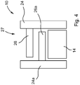
Figure 4 shows the apparatus according toFigure 3 seen in a direction IV ofFigure 3 , -
Figure 5 shows a vacuum gripper of a gripper assembly according to the invention while interacting with a sheet material, -
Figure 6 schematically shows the interaction between the sheet material and a mask of a vacuum gripper and -
Figure 7 shows a vacuum gripper of a gripper assembly according to a second embodiment of the invention in an exploded representation. - In
Figure 1 anapparatus 10 for recovering a layout from asheet material 12 is shown. It cooperates with asheet material 12 made from paper or cardboard. - The
sheet material 12 is provided on aconveyor unit 14, which is a conveyor belt in the example shown. The conveyor belt moves in a direction indicated byarrow 16. - The
conveyor unit 14 is equipped with avacuum system 15 for holding thesheet material 12 on an associated surface of theconveyor unit 14. - To this end the
conveyor unit 14 comprises a plurality ofsuction openings 15a which are fluidically connected to thevacuum system 15 such that thesheet material 12 may be held by sucking air through thesuction openings 15a (for better visibility only some of thesuction openings 15a are designated by a reference number). - Furthermore, the
apparatus 10 comprises alayout storage unit 18 on which one ormore blanks 20 of the layout 22 recovered from thesheet material 12 may be positioned. In the present case, thelayout storage unit 18 is a so-called stacking unit. This means that theblanks 20 of the layout 22 are stacked upon each other in thelayout storage unit 18. - Additionally, the
apparatus 10 has amanipulation unit 24 to which avacuum gripper 26 is connected. Themanipulation unit 24 and thecorresponding vacuum gripper 26 are shown in three different situations designated A, B and C. - The
manipulation unit 24, which is only represented in a schematic way, may comprise an industrial robot, which is adapted to manipulate therespective vacuum gripper 26 within a predefined scope of motion. - The
conveyor unit 14 and thevacuum gripper 26 form agripper assembly 27. - A method for separating the layout 22 from
waste 28 of thesheet material 12 may be performed by theapparatus 10. In other words a stripping or blanking method is performed. - An exemplified
sheet material 12 comprising a layout 22 with fourblanks 20 andwaste 28 is represented inFigure 2 . - In a first step of the method, the
sheet material 12 is provided. - Then, the
blanks 20 of the layout 22 are seized with the vacuum gripper 26 (cf. situation A inFigure 1 ). In order to do so, thevacuum gripper 26 is positioned over thesheet material 12 and only seizes the layout 22. - The
vacuum gripper 26 does not interact withwaste 28. - After that, as shown in situation B in
Figure 1 , the layout 22 is separated fromwaste 28. In the present case, the layout 22 is lifted by thevacuum gripper 26, whereaswaste 28 remains on theconveyor unit 14. - This is possible since the
vacuum system 15 is configured such that a vacuum force applied to the layout 22 by thevacuum system 15 is smaller than a vacuum force applied to the layout 22 by thevacuum gripper 26. - Subsequently, the
vacuum gripper 26 is moved into situation C, where it is positioned over theblank storage unit 18. Theblanks 20 are stacked on theblank storage unit 18 or onother blanks 20 already being positioned thereon. Thereafter, the interaction between thevacuum gripper 26 and theblanks 20 is terminated and thevacuum gripper 26 may be moved back to situation A by themanipulation unit 24. -
Figures 3 and4 show a second embodiment of theapparatus 10. This embodiment differs from the embodiment explained above in that it comprises anadditional vacuum gripper 26a, which is connected to a respectiveadditional manipulation unit 24a. - Both
vacuum grippers single conveyor unit 14 and one singlelayout storage unit 18. - The vacuum grippers 26, 26a may be operated according to two variants. Either both
vacuum grippers single sheet material 12 in a sense thatvacuum gripper 26 seizes a first portion of the layout and places it on thelayout storage unit 18 andadditional vacuum gripper 26a seizes a remaining second portion of the layout and places it on thelayout storage unit 18. Alternatively, everysecond sheet material 12 being provided by theconveyor unit 14 may be treated by thevacuum gripper 26 and everyother sheet material 12 by theadditional vacuum gripper 26a. - As shown in
Figure 3 , in both variants bothvacuum grippers same trajectory 30. - As far as the implementation of the method for separating a layout from waste of a sheet material with the second embodiment is concerned, the above explanations apply in an analogous way.
- In
Figures 5 to 7 thevacuum gripper 26 is shown in detail. Also anexemplary sheet material 12 is shown. As theadditional vacuum gripper 26a is identical, a specific explanation thereof will be omitted. - The
vacuum gripper 26 comprises agripper body 32. On a gripping side thereof an array ofair flow openings air flow openings air flow openings sheet material 12. - As can be seen from
Figures 5 and6 , only theairflow openings 34a associated with the layout 22, i.e. with one ormore blanks 20 of the layout 22, are open. The remainingair flow openings 34b are closed because they are covered with amask 36. In doing so, themask 36 does not interfere with theair flow openings 34a associated with the layout 22. - Consequently, the
vacuum gripper 26 is adapted to the geometry of the layout 22 in that in can only seize theblanks 20, when positioned above thesheet material 12.Waste 28 is not gripped by thevacuum gripper 26. Therefore, such avacuum gripper 26 is well suited for separating a layout 22 fromwaste 28. - As can best be seen from
Figure 6 , the array ofair flow openings sheet material 12 to be manipulated by thevacuum gripper 26. - The array of
air flow openings mask 36 to the geometry of the layout 22, the vacuum gripper is suitable for recovering a very large variety of different types of layout 22. - A further embodiment of the
vacuum gripper 26 is shown inFigure 7 . In this embodiment, thevacuum gripper 26 is magnetic, more specifically amagnetic cover 38 is attached to the gripping side of thevacuum gripper 26, e.g. by gluing. - The
mask 36 is now positioned between themagnetic cover 38 and amagnetic sheet 40 and thereby securely attached to thevacuum gripper 26. - The
mask 36 is made from non-magnetic material and therefore can be easily exchanged by separating themagnetic sheet 40 from thevacuum gripper 26 and positioning adifferent mask 36 on themagnetic cover 38. - As can be seen from the figures, an array of holes is provided both on the
magnetic cover 38 and themagnetic sheet 40. These arrays of holes corresponds to the array ofair flow openings magnetic cover 38 nor themagnetic sheet 40 is able to block or obstruct theair flow openings vacuum gripper 26 to a different geometry of the layout 22, it is not necessary to exchange or adapt themagnetic cover 38 or themagnetic sheet 40. - Apart from these structural differences the functionality of the
vacuum gripper 26 according to the second embodiment is not different from thevacuum gripper 26 explained with reference toFigures 5 and6 .
Claims (14)
- Gripper assembly (27) for recovering a layout (22) from a sheet material (12), especially from paper or cardboard, comprisinga conveyor unit (14) for providing the sheet material (12), anda vacuum gripper (26) being adapted for interacting with sheet material (12) provided by the conveyor unit (14), the vacuum gripper (26) comprising a gripper body (32) on which an array of air flow openings (34a, 34b) is arranged, each opening (34a, 34b) being adapted to seize at least a portion of the sheet material (12) by applying a vacuum force thereto,wherein air flow openings (34a, 34b) associated with one or more blanks (20) of the layout (22) are selectively open and air flow openings (34a, 34b) associated to waste (28) of the sheet material (12) are selectively closed,characterised in that the conveyor unit (14) is equipped with a vacuum system (15) for holding the sheet material (12) on the conveyor unit (14).
- Gripper assembly (27) according to claim 1, characterized in that the array of air flow openings (34a, 34b) covers a predefined maximum format of the sheet material (12) to be manipulated by the vacuum gripper (26).
- Gripper assembly (27) according to claim 1 or 2, characterized in that the array of air flow openings (34a, 34b) is arranged on a gripping side of the gripper body (32), wherein the gripping side is equipped with a mask (36), which selectively covers air flow openings (34b) being associated with waste (28) and selectively does not interfere with air flow openings (34a) associated with one or more blanks (20) of the layout (22).
- Gripper assembly (27) according to claim 3, characterized in that the gripping side of the vacuum gripper (26) is magnetic, especially wherein a magnetic cover (38) is attached to the gripping side of the vacuum gripper (26).
- Gripper assembly (27) according to claim 4, characterized in that the mask (36) is positioned between the magnetic side of the vacuum gripper (26) and a magnetic sheet (40) covering the mask (36) on its side opposing the vacuum gripper (26).
- Gripper assembly (27) according to any of the preceding claims, characterized in that the conveyor unit (14) comprises a plurality of suction openings (15a) which are fluidically connected to the vacuum system (15) such that the sheet material (12) may be held on the conveyor unit (14) by sucking air through the suction openings (15a) by the vacuum system (15), especially wherein a configuration of the suction openings (15a) is independent from the size and/or shape of the sheet material (12) to be processed.
- Gripper assembly (27) according to any of the preceding claims, characterized in that the vacuum system (15) is configured such that a vacuum force applied to one or more blanks by the vacuum system (15) is smaller than a vacuum force applied to the one or more blanks by the vacuum gripper (26).
- Apparatus (10) for recovering a layout (22) from a sheet material (12), especially from paper or cardboard, comprisinga gripper assembly (27) according to any of the preceding claims, wherein the sheet material (12) comprising the layout (22) and waste (28) is to be provided by the conveyor unit (14) of the gripper assembly (27), and wherein the vacuum gripper (26) of the gripper assembly (27) is connected to a manipulation unit (24), anda layout storage unit (18) on which one or more blanks (20) of the layout (22) recovered from the sheet material (12) may be positioned.
- Apparatus (10) according to claim 8, characterized by one or more additional vacuum grippers (26a), wherein each additional vacuum gripper (26a) is connected to a respective additional manipulation unit (24a).
- Apparatus (10) according to claim 8 or 9, characterized in that at least one of the manipulation unit (24) and the additional manipulation unit (24a) comprises an industrial robot, which is adapted to manipulate the respective vacuum gripper (26, 26a) within a predefined scope of motion.
- Apparatus (10) according to any of claims 8 to 10, characterized in that the blank storage unit (18) is a stacking unit.
- Method for separating a layout (22) from waste (28) of a sheet material (12), especially from paper or cardboard, comprising the following stepsa) providing a sheet material (12) on a conveyor unit (14), wherein the sheet material (12) comprises a layout (22) with one or more blanks (20) and waste (28), and wherein the sheet material (12) is held on the conveyor unit (14) by a vacuum system (15) of the conveyor unit (14),b) seizing the one or more blanks (20) with a vacuum gripper (26), preferably a vacuum gripper (26) of a gripper assembly (27) according to claims 1 to 7, while not interacting with waste (28), and thereafterc) separating the one or more blanks (20) from waste (28).
- Method according to claim 12, characterized in that after step c) the blanks (20) are moved to a blank storage unit (18), especially a stacking unit or a further conveyor unit.
- Method according to claim 12 or 13, characterized in that during step b) the vacuum gripper (26) is positioned over the sheet material (12), wherein the vacuum gripper (26) selectively seizes the blanks (20) without cooperating with waste (28).
Applications Claiming Priority (2)
| Application Number | Priority Date | Filing Date | Title |
|---|---|---|---|
| EP19020133 | 2019-03-18 | ||
| PCT/EP2020/025134 WO2020187452A1 (en) | 2019-03-18 | 2020-03-17 | Gripper assembly, apparatus for recovering a layout from a sheet material and method for separating a layout from waste of a sheet material |
Publications (2)
| Publication Number | Publication Date |
|---|---|
| EP3941866A1 EP3941866A1 (en) | 2022-01-26 |
| EP3941866B1 true EP3941866B1 (en) | 2022-12-07 |
Family
ID=65903872
Family Applications (1)
| Application Number | Title | Priority Date | Filing Date |
|---|---|---|---|
| EP20711503.1A Active EP3941866B1 (en) | 2019-03-18 | 2020-03-17 | Gripper assembly, apparatus for recovering a layout from a sheet material and method for separating a layout from waste of a sheet material |
Country Status (8)
| Country | Link |
|---|---|
| US (1) | US11970353B2 (en) |
| EP (1) | EP3941866B1 (en) |
| JP (1) | JP7389814B2 (en) |
| KR (1) | KR102405160B1 (en) |
| CN (1) | CN113573997B (en) |
| ES (1) | ES2934974T3 (en) |
| TW (1) | TWI742566B (en) |
| WO (1) | WO2020187452A1 (en) |
Families Citing this family (2)
| Publication number | Priority date | Publication date | Assignee | Title |
|---|---|---|---|---|
| CN112456141A (en) * | 2020-12-08 | 2021-03-09 | 安捷利(番禺)电子实业有限公司 | Sucker clamp adjustable device |
| KR102629298B1 (en) * | 2023-08-02 | 2024-01-25 | 주식회사 에이트테크 | Apparatus for air redirection |
Family Cites Families (20)
| Publication number | Priority date | Publication date | Assignee | Title |
|---|---|---|---|---|
| DE3763395D1 (en) * | 1986-11-10 | 1990-08-02 | Haas Laser Systems Ag | METHOD FOR TRANSPORTING PERFORATED PLATE-SHAPED OBJECTS. |
| JPH06269586A (en) * | 1993-03-17 | 1994-09-27 | Mitsubishi Electric Corp | Cutting machine and method for picking up workpiece to be cut by the machine |
| US5883357A (en) * | 1996-03-25 | 1999-03-16 | Case Western Reserve University | Selective vacuum gripper |
| US6139079A (en) * | 1997-10-20 | 2000-10-31 | Motorola, Inc. | Universal transport apparatus |
| KR100305298B1 (en) * | 1998-07-14 | 2001-12-12 | 송병준 | Sheet separating method and apparatus |
| US6227541B1 (en) * | 1999-07-01 | 2001-05-08 | Kimberly-Clark Worldwide, Inc. | Multiple conveyor assembly and method for rotating and placing a strip of material on a substrate |
| EP1074354A1 (en) * | 1999-07-26 | 2001-02-07 | Byung Jun Song | Apparatus and method for separating cutout blanks from sheet material |
| US7458927B2 (en) * | 2005-10-07 | 2008-12-02 | C.G. Bretting Manufacturing Co., Inc. | Interfolder with pre-forming transfer roll |
| JP2008007254A (en) * | 2006-06-28 | 2008-01-17 | Sharp Corp | Method and apparatus for transporting sheet-like substrate |
| JP5067250B2 (en) * | 2008-04-18 | 2012-11-07 | 村田機械株式会社 | Plate material transfer device |
| DE102008025468B3 (en) * | 2008-05-28 | 2009-06-04 | WINKLER+DüNNEBIER AG | Suction hole covering device for suction roller to transport e.g. folding box cuts of paperboard box, has flexible mask foil with suction openings arranged depending on format of flat material pieces to be transported |
| JP2010005769A (en) * | 2008-06-30 | 2010-01-14 | Ihi Corp | Depalletizing apparatus and depalletizing method |
| JP2014502216A (en) | 2010-11-19 | 2014-01-30 | ボブスト メックス ソシエテ アノニム | Equipment for a unit that ejects debris in packaging production machinery |
| KR101787977B1 (en) * | 2011-04-21 | 2017-10-19 | 엘지디스플레이 주식회사 | Release Apparatus |
| US9010827B2 (en) | 2011-11-18 | 2015-04-21 | Nike, Inc. | Switchable plate manufacturing vacuum tool |
| WO2013164812A1 (en) | 2012-05-02 | 2013-11-07 | Highcon Systems Ltd | Method and system for stripping and blanking a cardboard |
| DE102013201247B4 (en) * | 2013-01-25 | 2018-03-22 | J. Schmalz Gmbh | area vacuum |
| US8876100B1 (en) * | 2013-09-04 | 2014-11-04 | Xerox Corporation | Robotic belt finishing system for high speed multiple card pick to sequenced stack |
| EP2965899A1 (en) * | 2014-07-09 | 2016-01-13 | Cellpack AG | Device for the separation of flexible packaging products |
| TWI638759B (en) | 2018-04-17 | 2018-10-21 | 威光自動化科技股份有限公司 | Negative pressure adsorber for shaped sheet objects |
-
2020
- 2020-03-17 EP EP20711503.1A patent/EP3941866B1/en active Active
- 2020-03-17 WO PCT/EP2020/025134 patent/WO2020187452A1/en not_active Ceased
- 2020-03-17 JP JP2021555461A patent/JP7389814B2/en active Active
- 2020-03-17 TW TW109108780A patent/TWI742566B/en active
- 2020-03-17 US US17/593,290 patent/US11970353B2/en active Active
- 2020-03-17 KR KR1020217032301A patent/KR102405160B1/en active Active
- 2020-03-17 CN CN202080021702.1A patent/CN113573997B/en active Active
- 2020-03-17 ES ES20711503T patent/ES2934974T3/en active Active
Also Published As
| Publication number | Publication date |
|---|---|
| BR112021016600A2 (en) | 2021-11-03 |
| TW202039344A (en) | 2020-11-01 |
| JP7389814B2 (en) | 2023-11-30 |
| EP3941866A1 (en) | 2022-01-26 |
| CN113573997B (en) | 2024-03-12 |
| KR102405160B1 (en) | 2022-06-02 |
| CN113573997A (en) | 2021-10-29 |
| US20220194730A1 (en) | 2022-06-23 |
| US11970353B2 (en) | 2024-04-30 |
| KR20210128495A (en) | 2021-10-26 |
| ES2934974T3 (en) | 2023-02-28 |
| JP2022525611A (en) | 2022-05-18 |
| TWI742566B (en) | 2021-10-11 |
| WO2020187452A1 (en) | 2020-09-24 |
Similar Documents
| Publication | Publication Date | Title |
|---|---|---|
| JP7068150B2 (en) | Hand, robot system and work removal method | |
| US9352917B2 (en) | Method for removing a substantially planar work piece from the top of a stack of work pieces | |
| US8868231B2 (en) | Flexible production collating system | |
| US11970353B2 (en) | Gripper assembly, apparatus for recovering a layout from a sheet material and method for separating a layout from waste of a sheet material | |
| EP0687532B1 (en) | Sheet cutting apparatus | |
| US5647725A (en) | Method for preparing a sheet stack for processing in a sheet-processing machine | |
| EP4422868A1 (en) | A method and an apparatus for processing of printable panels | |
| EP2599720A1 (en) | Multi-track jacket closing machine | |
| JPH03500746A (en) | Equipment for die-cutting and separating sheets of paper, cardboard or similar materials | |
| EP1935820A2 (en) | Sheet processing machine with sheet brake device and method for cleaning a sheet brake device | |
| US3430542A (en) | Material processing apparatus with relatively movable processing components | |
| BR112021016600B1 (en) | CLAMPING ASSEMBLY, APPARATUS FOR RECOVERING A LAYOUT FROM SHEET MATERIAL AND METHOD FOR SEPARATING A LAYOUT FROM WASTE FROM SHEET MATERIAL | |
| EP3882186B1 (en) | Cover member for a storing means for stacked flat elements | |
| KR102790121B1 (en) | Apparatus for detaching metal foil on the substrate | |
| JP3965841B2 (en) | Program creation device | |
| CN223749764U (en) | Panel cutting device | |
| JP2026514542A (en) | Method of handling sheets using a die-cutting machine and die-cutting machine | |
| WO2026047436A1 (en) | Contact lens packaging processing | |
| JPH0489145A (en) | Two-pieces arraying and transporting device for deformed blank material of transfer press | |
| JP2024119604A (en) | Pre-cut processing method |
Legal Events
| Date | Code | Title | Description |
|---|---|---|---|
| STAA | Information on the status of an ep patent application or granted ep patent |
Free format text: STATUS: UNKNOWN |
|
| STAA | Information on the status of an ep patent application or granted ep patent |
Free format text: STATUS: THE INTERNATIONAL PUBLICATION HAS BEEN MADE |
|
| PUAI | Public reference made under article 153(3) epc to a published international application that has entered the european phase |
Free format text: ORIGINAL CODE: 0009012 |
|
| STAA | Information on the status of an ep patent application or granted ep patent |
Free format text: STATUS: REQUEST FOR EXAMINATION WAS MADE |
|
| 17P | Request for examination filed |
Effective date: 20210913 |
|
| AK | Designated contracting states |
Kind code of ref document: A1 Designated state(s): AL AT BE BG CH CY CZ DE DK EE ES FI FR GB GR HR HU IE IS IT LI LT LU LV MC MK MT NL NO PL PT RO RS SE SI SK SM TR |
|
| DAV | Request for validation of the european patent (deleted) | ||
| DAX | Request for extension of the european patent (deleted) | ||
| RIC1 | Information provided on ipc code assigned before grant |
Ipc: B65G 47/91 20060101ALI20220831BHEP Ipc: B25J 15/06 20060101ALI20220831BHEP Ipc: B26D 7/18 20060101ALI20220831BHEP Ipc: B65H 29/24 20060101ALI20220831BHEP Ipc: B65H 5/22 20060101AFI20220831BHEP |
|
| GRAP | Despatch of communication of intention to grant a patent |
Free format text: ORIGINAL CODE: EPIDOSNIGR1 |
|
| STAA | Information on the status of an ep patent application or granted ep patent |
Free format text: STATUS: GRANT OF PATENT IS INTENDED |
|
| GRAS | Grant fee paid |
Free format text: ORIGINAL CODE: EPIDOSNIGR3 |
|
| GRAA | (expected) grant |
Free format text: ORIGINAL CODE: 0009210 |
|
| STAA | Information on the status of an ep patent application or granted ep patent |
Free format text: STATUS: THE PATENT HAS BEEN GRANTED |
|
| INTG | Intention to grant announced |
Effective date: 20221012 |
|
| AK | Designated contracting states |
Kind code of ref document: B1 Designated state(s): AL AT BE BG CH CY CZ DE DK EE ES FI FR GB GR HR HU IE IS IT LI LT LU LV MC MK MT NL NO PL PT RO RS SE SI SK SM TR |
|
| REG | Reference to a national code |
Ref country code: GB Ref legal event code: FG4D |
|
| REG | Reference to a national code |
Ref country code: CH Ref legal event code: EP Ref country code: AT Ref legal event code: REF Ref document number: 1536203 Country of ref document: AT Kind code of ref document: T Effective date: 20221215 |
|
| REG | Reference to a national code |
Ref country code: DE Ref legal event code: R096 Ref document number: 602020006788 Country of ref document: DE |
|
| REG | Reference to a national code |
Ref country code: IE Ref legal event code: FG4D |
|
| REG | Reference to a national code |
Ref country code: ES Ref legal event code: FG2A Ref document number: 2934974 Country of ref document: ES Kind code of ref document: T3 Effective date: 20230228 |
|
| REG | Reference to a national code |
Ref country code: LT Ref legal event code: MG9D |
|
| REG | Reference to a national code |
Ref country code: NL Ref legal event code: MP Effective date: 20221207 |
|
| PG25 | Lapsed in a contracting state [announced via postgrant information from national office to epo] |
Ref country code: SE Free format text: LAPSE BECAUSE OF FAILURE TO SUBMIT A TRANSLATION OF THE DESCRIPTION OR TO PAY THE FEE WITHIN THE PRESCRIBED TIME-LIMIT Effective date: 20221207 Ref country code: NO Free format text: LAPSE BECAUSE OF FAILURE TO SUBMIT A TRANSLATION OF THE DESCRIPTION OR TO PAY THE FEE WITHIN THE PRESCRIBED TIME-LIMIT Effective date: 20230307 Ref country code: LT Free format text: LAPSE BECAUSE OF FAILURE TO SUBMIT A TRANSLATION OF THE DESCRIPTION OR TO PAY THE FEE WITHIN THE PRESCRIBED TIME-LIMIT Effective date: 20221207 Ref country code: FI Free format text: LAPSE BECAUSE OF FAILURE TO SUBMIT A TRANSLATION OF THE DESCRIPTION OR TO PAY THE FEE WITHIN THE PRESCRIBED TIME-LIMIT Effective date: 20221207 |
|
| REG | Reference to a national code |
Ref country code: AT Ref legal event code: MK05 Ref document number: 1536203 Country of ref document: AT Kind code of ref document: T Effective date: 20221207 |
|
| PG25 | Lapsed in a contracting state [announced via postgrant information from national office to epo] |
Ref country code: RS Free format text: LAPSE BECAUSE OF FAILURE TO SUBMIT A TRANSLATION OF THE DESCRIPTION OR TO PAY THE FEE WITHIN THE PRESCRIBED TIME-LIMIT Effective date: 20221207 Ref country code: PL Free format text: LAPSE BECAUSE OF FAILURE TO SUBMIT A TRANSLATION OF THE DESCRIPTION OR TO PAY THE FEE WITHIN THE PRESCRIBED TIME-LIMIT Effective date: 20221207 Ref country code: LV Free format text: LAPSE BECAUSE OF FAILURE TO SUBMIT A TRANSLATION OF THE DESCRIPTION OR TO PAY THE FEE WITHIN THE PRESCRIBED TIME-LIMIT Effective date: 20221207 Ref country code: HR Free format text: LAPSE BECAUSE OF FAILURE TO SUBMIT A TRANSLATION OF THE DESCRIPTION OR TO PAY THE FEE WITHIN THE PRESCRIBED TIME-LIMIT Effective date: 20221207 Ref country code: GR Free format text: LAPSE BECAUSE OF FAILURE TO SUBMIT A TRANSLATION OF THE DESCRIPTION OR TO PAY THE FEE WITHIN THE PRESCRIBED TIME-LIMIT Effective date: 20230308 |
|
| PG25 | Lapsed in a contracting state [announced via postgrant information from national office to epo] |
Ref country code: NL Free format text: LAPSE BECAUSE OF FAILURE TO SUBMIT A TRANSLATION OF THE DESCRIPTION OR TO PAY THE FEE WITHIN THE PRESCRIBED TIME-LIMIT Effective date: 20221207 |
|
| PG25 | Lapsed in a contracting state [announced via postgrant information from national office to epo] |
Ref country code: SM Free format text: LAPSE BECAUSE OF FAILURE TO SUBMIT A TRANSLATION OF THE DESCRIPTION OR TO PAY THE FEE WITHIN THE PRESCRIBED TIME-LIMIT Effective date: 20221207 Ref country code: RO Free format text: LAPSE BECAUSE OF FAILURE TO SUBMIT A TRANSLATION OF THE DESCRIPTION OR TO PAY THE FEE WITHIN THE PRESCRIBED TIME-LIMIT Effective date: 20221207 Ref country code: PT Free format text: LAPSE BECAUSE OF FAILURE TO SUBMIT A TRANSLATION OF THE DESCRIPTION OR TO PAY THE FEE WITHIN THE PRESCRIBED TIME-LIMIT Effective date: 20230410 Ref country code: EE Free format text: LAPSE BECAUSE OF FAILURE TO SUBMIT A TRANSLATION OF THE DESCRIPTION OR TO PAY THE FEE WITHIN THE PRESCRIBED TIME-LIMIT Effective date: 20221207 Ref country code: CZ Free format text: LAPSE BECAUSE OF FAILURE TO SUBMIT A TRANSLATION OF THE DESCRIPTION OR TO PAY THE FEE WITHIN THE PRESCRIBED TIME-LIMIT Effective date: 20221207 Ref country code: AT Free format text: LAPSE BECAUSE OF FAILURE TO SUBMIT A TRANSLATION OF THE DESCRIPTION OR TO PAY THE FEE WITHIN THE PRESCRIBED TIME-LIMIT Effective date: 20221207 |
|
| PG25 | Lapsed in a contracting state [announced via postgrant information from national office to epo] |
Ref country code: SK Free format text: LAPSE BECAUSE OF FAILURE TO SUBMIT A TRANSLATION OF THE DESCRIPTION OR TO PAY THE FEE WITHIN THE PRESCRIBED TIME-LIMIT Effective date: 20221207 Ref country code: IS Free format text: LAPSE BECAUSE OF FAILURE TO SUBMIT A TRANSLATION OF THE DESCRIPTION OR TO PAY THE FEE WITHIN THE PRESCRIBED TIME-LIMIT Effective date: 20230407 Ref country code: AL Free format text: LAPSE BECAUSE OF FAILURE TO SUBMIT A TRANSLATION OF THE DESCRIPTION OR TO PAY THE FEE WITHIN THE PRESCRIBED TIME-LIMIT Effective date: 20221207 |
|
| REG | Reference to a national code |
Ref country code: DE Ref legal event code: R097 Ref document number: 602020006788 Country of ref document: DE |
|
| PLBE | No opposition filed within time limit |
Free format text: ORIGINAL CODE: 0009261 |
|
| STAA | Information on the status of an ep patent application or granted ep patent |
Free format text: STATUS: NO OPPOSITION FILED WITHIN TIME LIMIT |
|
| PG25 | Lapsed in a contracting state [announced via postgrant information from national office to epo] |
Ref country code: MC Free format text: LAPSE BECAUSE OF FAILURE TO SUBMIT A TRANSLATION OF THE DESCRIPTION OR TO PAY THE FEE WITHIN THE PRESCRIBED TIME-LIMIT Effective date: 20221207 Ref country code: DK Free format text: LAPSE BECAUSE OF FAILURE TO SUBMIT A TRANSLATION OF THE DESCRIPTION OR TO PAY THE FEE WITHIN THE PRESCRIBED TIME-LIMIT Effective date: 20221207 |
|
| 26N | No opposition filed |
Effective date: 20230908 |
|
| PG25 | Lapsed in a contracting state [announced via postgrant information from national office to epo] |
Ref country code: SI Free format text: LAPSE BECAUSE OF FAILURE TO SUBMIT A TRANSLATION OF THE DESCRIPTION OR TO PAY THE FEE WITHIN THE PRESCRIBED TIME-LIMIT Effective date: 20221207 |
|
| REG | Reference to a national code |
Ref country code: BE Ref legal event code: MM Effective date: 20230331 |
|
| PG25 | Lapsed in a contracting state [announced via postgrant information from national office to epo] |
Ref country code: LU Free format text: LAPSE BECAUSE OF NON-PAYMENT OF DUE FEES Effective date: 20230317 |
|
| REG | Reference to a national code |
Ref country code: IE Ref legal event code: MM4A |
|
| PG25 | Lapsed in a contracting state [announced via postgrant information from national office to epo] |
Ref country code: IE Free format text: LAPSE BECAUSE OF NON-PAYMENT OF DUE FEES Effective date: 20230317 |
|
| PG25 | Lapsed in a contracting state [announced via postgrant information from national office to epo] |
Ref country code: BE Free format text: LAPSE BECAUSE OF NON-PAYMENT OF DUE FEES Effective date: 20230331 |
|
| PG25 | Lapsed in a contracting state [announced via postgrant information from national office to epo] |
Ref country code: BG Free format text: LAPSE BECAUSE OF FAILURE TO SUBMIT A TRANSLATION OF THE DESCRIPTION OR TO PAY THE FEE WITHIN THE PRESCRIBED TIME-LIMIT Effective date: 20221207 |
|
| PG25 | Lapsed in a contracting state [announced via postgrant information from national office to epo] |
Ref country code: BG Free format text: LAPSE BECAUSE OF FAILURE TO SUBMIT A TRANSLATION OF THE DESCRIPTION OR TO PAY THE FEE WITHIN THE PRESCRIBED TIME-LIMIT Effective date: 20221207 |
|
| PGFP | Annual fee paid to national office [announced via postgrant information from national office to epo] |
Ref country code: ES Payment date: 20250408 Year of fee payment: 6 |
|
| PGFP | Annual fee paid to national office [announced via postgrant information from national office to epo] |
Ref country code: CH Payment date: 20250401 Year of fee payment: 6 |
|
| PG25 | Lapsed in a contracting state [announced via postgrant information from national office to epo] |
Ref country code: CY Free format text: LAPSE BECAUSE OF FAILURE TO SUBMIT A TRANSLATION OF THE DESCRIPTION OR TO PAY THE FEE WITHIN THE PRESCRIBED TIME-LIMIT; INVALID AB INITIO Effective date: 20200317 |
|
| PG25 | Lapsed in a contracting state [announced via postgrant information from national office to epo] |
Ref country code: HU Free format text: LAPSE BECAUSE OF FAILURE TO SUBMIT A TRANSLATION OF THE DESCRIPTION OR TO PAY THE FEE WITHIN THE PRESCRIBED TIME-LIMIT; INVALID AB INITIO Effective date: 20200317 |
|
| PG25 | Lapsed in a contracting state [announced via postgrant information from national office to epo] |
Ref country code: TR Free format text: LAPSE BECAUSE OF FAILURE TO SUBMIT A TRANSLATION OF THE DESCRIPTION OR TO PAY THE FEE WITHIN THE PRESCRIBED TIME-LIMIT Effective date: 20221207 |
|
| REG | Reference to a national code |
Ref country code: CH Ref legal event code: U11 Free format text: ST27 STATUS EVENT CODE: U-0-0-U10-U11 (AS PROVIDED BY THE NATIONAL OFFICE) Effective date: 20260401 |
|
| PGFP | Annual fee paid to national office [announced via postgrant information from national office to epo] |
Ref country code: GB Payment date: 20260324 Year of fee payment: 7 |
|
| PGFP | Annual fee paid to national office [announced via postgrant information from national office to epo] |
Ref country code: DE Payment date: 20260319 Year of fee payment: 7 |
|
| PGFP | Annual fee paid to national office [announced via postgrant information from national office to epo] |
Ref country code: IT Payment date: 20260324 Year of fee payment: 7 |
|
| PGFP | Annual fee paid to national office [announced via postgrant information from national office to epo] |
Ref country code: FR Payment date: 20260323 Year of fee payment: 7 |