EP3941031A1 - Digital camera with printer - Google Patents
Digital camera with printer Download PDFInfo
- Publication number
- EP3941031A1 EP3941031A1 EP19919580.1A EP19919580A EP3941031A1 EP 3941031 A1 EP3941031 A1 EP 3941031A1 EP 19919580 A EP19919580 A EP 19919580A EP 3941031 A1 EP3941031 A1 EP 3941031A1
- Authority
- EP
- European Patent Office
- Prior art keywords
- digital camera
- printer
- image
- unit
- composite image
- Prior art date
- Legal status (The legal status is an assumption and is not a legal conclusion. Google has not performed a legal analysis and makes no representation as to the accuracy of the status listed.)
- Granted
Links
Images








Classifications
-
- B—PERFORMING OPERATIONS; TRANSPORTING
- B41—PRINTING; LINING MACHINES; TYPEWRITERS; STAMPS
- B41J—TYPEWRITERS; SELECTIVE PRINTING MECHANISMS, i.e. MECHANISMS PRINTING OTHERWISE THAN FROM A FORME; CORRECTION OF TYPOGRAPHICAL ERRORS
- B41J3/00—Typewriters or selective printing or marking mechanisms characterised by the purpose for which they are constructed
- B41J3/44—Typewriters or selective printing mechanisms having dual functions or combined with, or coupled to, apparatus performing other functions
- B41J3/445—Printers integrated in other types of apparatus, e.g. printers integrated in cameras
-
- H—ELECTRICITY
- H04—ELECTRIC COMMUNICATION TECHNIQUE
- H04N—PICTORIAL COMMUNICATION, e.g. TELEVISION
- H04N23/00—Cameras or camera modules comprising electronic image sensors; Control thereof
- H04N23/60—Control of cameras or camera modules
- H04N23/66—Remote control of cameras or camera parts, e.g. by remote control devices
- H04N23/661—Transmitting camera control signals through networks, e.g. control via the Internet
- H04N23/662—Transmitting camera control signals through networks, e.g. control via the Internet by using camera arrangements where one camera controls another camera to affect the control of camera image capture, e.g. placing the camera in a desirable condition to capture a desired image
-
- G—PHYSICS
- G03—PHOTOGRAPHY; CINEMATOGRAPHY; ANALOGOUS TECHNIQUES USING WAVES OTHER THAN OPTICAL WAVES; ELECTROGRAPHY; HOLOGRAPHY
- G03B—APPARATUS OR ARRANGEMENTS FOR TAKING PHOTOGRAPHS OR FOR PROJECTING OR VIEWING THEM; APPARATUS OR ARRANGEMENTS EMPLOYING ANALOGOUS TECHNIQUES USING WAVES OTHER THAN OPTICAL WAVES; ACCESSORIES THEREFOR
- G03B17/00—Details of cameras or camera bodies; Accessories therefor
- G03B17/48—Details of cameras or camera bodies; Accessories therefor adapted for combination with other photographic or optical apparatus
- G03B17/50—Details of cameras or camera bodies; Accessories therefor adapted for combination with other photographic or optical apparatus with both developing and finishing apparatus
-
- H—ELECTRICITY
- H04—ELECTRIC COMMUNICATION TECHNIQUE
- H04N—PICTORIAL COMMUNICATION, e.g. TELEVISION
- H04N1/00—Scanning, transmission or reproduction of documents or the like, e.g. facsimile transmission; Details thereof
- H04N1/00127—Connection or combination of a still picture apparatus with another apparatus, e.g. for storage, processing or transmission of still picture signals or of information associated with a still picture
- H04N1/00132—Connection or combination of a still picture apparatus with another apparatus, e.g. for storage, processing or transmission of still picture signals or of information associated with a still picture in a digital photofinishing system, i.e. a system where digital photographic images undergo typical photofinishing processing, e.g. printing ordering
- H04N1/00137—Transmission
-
- H—ELECTRICITY
- H04—ELECTRIC COMMUNICATION TECHNIQUE
- H04N—PICTORIAL COMMUNICATION, e.g. TELEVISION
- H04N1/00—Scanning, transmission or reproduction of documents or the like, e.g. facsimile transmission; Details thereof
- H04N1/00127—Connection or combination of a still picture apparatus with another apparatus, e.g. for storage, processing or transmission of still picture signals or of information associated with a still picture
- H04N1/00132—Connection or combination of a still picture apparatus with another apparatus, e.g. for storage, processing or transmission of still picture signals or of information associated with a still picture in a digital photofinishing system, i.e. a system where digital photographic images undergo typical photofinishing processing, e.g. printing ordering
- H04N1/00148—Storage
-
- H—ELECTRICITY
- H04—ELECTRIC COMMUNICATION TECHNIQUE
- H04N—PICTORIAL COMMUNICATION, e.g. TELEVISION
- H04N1/00—Scanning, transmission or reproduction of documents or the like, e.g. facsimile transmission; Details thereof
- H04N1/00127—Connection or combination of a still picture apparatus with another apparatus, e.g. for storage, processing or transmission of still picture signals or of information associated with a still picture
- H04N1/00132—Connection or combination of a still picture apparatus with another apparatus, e.g. for storage, processing or transmission of still picture signals or of information associated with a still picture in a digital photofinishing system, i.e. a system where digital photographic images undergo typical photofinishing processing, e.g. printing ordering
- H04N1/00161—Viewing or previewing
-
- H—ELECTRICITY
- H04—ELECTRIC COMMUNICATION TECHNIQUE
- H04N—PICTORIAL COMMUNICATION, e.g. TELEVISION
- H04N1/00—Scanning, transmission or reproduction of documents or the like, e.g. facsimile transmission; Details thereof
- H04N1/00127—Connection or combination of a still picture apparatus with another apparatus, e.g. for storage, processing or transmission of still picture signals or of information associated with a still picture
- H04N1/00132—Connection or combination of a still picture apparatus with another apparatus, e.g. for storage, processing or transmission of still picture signals or of information associated with a still picture in a digital photofinishing system, i.e. a system where digital photographic images undergo typical photofinishing processing, e.g. printing ordering
- H04N1/00167—Processing or editing
-
- H—ELECTRICITY
- H04—ELECTRIC COMMUNICATION TECHNIQUE
- H04N—PICTORIAL COMMUNICATION, e.g. TELEVISION
- H04N1/00—Scanning, transmission or reproduction of documents or the like, e.g. facsimile transmission; Details thereof
- H04N1/00127—Connection or combination of a still picture apparatus with another apparatus, e.g. for storage, processing or transmission of still picture signals or of information associated with a still picture
- H04N1/00132—Connection or combination of a still picture apparatus with another apparatus, e.g. for storage, processing or transmission of still picture signals or of information associated with a still picture in a digital photofinishing system, i.e. a system where digital photographic images undergo typical photofinishing processing, e.g. printing ordering
- H04N1/00169—Digital image input
- H04N1/00172—Digital image input directly from a still digital camera or from a storage medium mounted in a still digital camera
-
- H—ELECTRICITY
- H04—ELECTRIC COMMUNICATION TECHNIQUE
- H04N—PICTORIAL COMMUNICATION, e.g. TELEVISION
- H04N1/00—Scanning, transmission or reproduction of documents or the like, e.g. facsimile transmission; Details thereof
- H04N1/00127—Connection or combination of a still picture apparatus with another apparatus, e.g. for storage, processing or transmission of still picture signals or of information associated with a still picture
- H04N1/00132—Connection or combination of a still picture apparatus with another apparatus, e.g. for storage, processing or transmission of still picture signals or of information associated with a still picture in a digital photofinishing system, i.e. a system where digital photographic images undergo typical photofinishing processing, e.g. printing ordering
- H04N1/00185—Image output
- H04N1/00188—Printing, e.g. prints or reprints
-
- H—ELECTRICITY
- H04—ELECTRIC COMMUNICATION TECHNIQUE
- H04N—PICTORIAL COMMUNICATION, e.g. TELEVISION
- H04N1/00—Scanning, transmission or reproduction of documents or the like, e.g. facsimile transmission; Details thereof
- H04N1/00127—Connection or combination of a still picture apparatus with another apparatus, e.g. for storage, processing or transmission of still picture signals or of information associated with a still picture
- H04N1/00132—Connection or combination of a still picture apparatus with another apparatus, e.g. for storage, processing or transmission of still picture signals or of information associated with a still picture in a digital photofinishing system, i.e. a system where digital photographic images undergo typical photofinishing processing, e.g. printing ordering
- H04N1/00185—Image output
- H04N1/00196—Creation of a photo-montage, e.g. photoalbum
-
- H—ELECTRICITY
- H04—ELECTRIC COMMUNICATION TECHNIQUE
- H04N—PICTORIAL COMMUNICATION, e.g. TELEVISION
- H04N1/00—Scanning, transmission or reproduction of documents or the like, e.g. facsimile transmission; Details thereof
- H04N1/00127—Connection or combination of a still picture apparatus with another apparatus, e.g. for storage, processing or transmission of still picture signals or of information associated with a still picture
- H04N1/00249—Connection or combination of a still picture apparatus with another apparatus, e.g. for storage, processing or transmission of still picture signals or of information associated with a still picture with a photographic apparatus, e.g. a photographic printer or a projector
- H04N1/00265—Connection or combination of a still picture apparatus with another apparatus, e.g. for storage, processing or transmission of still picture signals or of information associated with a still picture with a photographic apparatus, e.g. a photographic printer or a projector with a photographic printing apparatus
-
- H—ELECTRICITY
- H04—ELECTRIC COMMUNICATION TECHNIQUE
- H04N—PICTORIAL COMMUNICATION, e.g. TELEVISION
- H04N1/00—Scanning, transmission or reproduction of documents or the like, e.g. facsimile transmission; Details thereof
- H04N1/00127—Connection or combination of a still picture apparatus with another apparatus, e.g. for storage, processing or transmission of still picture signals or of information associated with a still picture
- H04N1/00347—Connection or combination of a still picture apparatus with another apparatus, e.g. for storage, processing or transmission of still picture signals or of information associated with a still picture with another still picture apparatus, e.g. hybrid still picture apparatus
-
- H—ELECTRICITY
- H04—ELECTRIC COMMUNICATION TECHNIQUE
- H04N—PICTORIAL COMMUNICATION, e.g. TELEVISION
- H04N1/00—Scanning, transmission or reproduction of documents or the like, e.g. facsimile transmission; Details thereof
- H04N1/0035—User-machine interface; Control console
- H04N1/00405—Output means
- H04N1/00408—Display of information to the user, e.g. menus
- H04N1/0044—Display of information to the user, e.g. menus for image preview or review, e.g. to help the user position a sheet
-
- H—ELECTRICITY
- H04—ELECTRIC COMMUNICATION TECHNIQUE
- H04N—PICTORIAL COMMUNICATION, e.g. TELEVISION
- H04N1/00—Scanning, transmission or reproduction of documents or the like, e.g. facsimile transmission; Details thereof
- H04N1/0035—User-machine interface; Control console
- H04N1/00405—Output means
- H04N1/00477—Indicating status, e.g. of a job
-
- H—ELECTRICITY
- H04—ELECTRIC COMMUNICATION TECHNIQUE
- H04N—PICTORIAL COMMUNICATION, e.g. TELEVISION
- H04N1/00—Scanning, transmission or reproduction of documents or the like, e.g. facsimile transmission; Details thereof
- H04N1/0035—User-machine interface; Control console
- H04N1/00405—Output means
- H04N1/00488—Output means providing an audible output to the user
-
- H—ELECTRICITY
- H04—ELECTRIC COMMUNICATION TECHNIQUE
- H04N—PICTORIAL COMMUNICATION, e.g. TELEVISION
- H04N1/00—Scanning, transmission or reproduction of documents or the like, e.g. facsimile transmission; Details thereof
- H04N1/32—Circuits or arrangements for control or supervision between transmitter and receiver or between image input and image output device, e.g. between a still-image camera and its memory or between a still-image camera and a printer device
- H04N1/32005—Automation of particular receiver jobs, e.g. rejecting unwanted calls
- H04N1/32016—Automation of particular receiver jobs, e.g. rejecting unwanted calls according to the caller's identification, e.g. fax number
-
- H—ELECTRICITY
- H04—ELECTRIC COMMUNICATION TECHNIQUE
- H04N—PICTORIAL COMMUNICATION, e.g. TELEVISION
- H04N1/00—Scanning, transmission or reproduction of documents or the like, e.g. facsimile transmission; Details thereof
- H04N1/32—Circuits or arrangements for control or supervision between transmitter and receiver or between image input and image output device, e.g. between a still-image camera and its memory or between a still-image camera and a printer device
- H04N1/32101—Display, printing, storage or transmission of additional information, e.g. ID code, date and time or title
- H04N1/32128—Display, printing, storage or transmission of additional information, e.g. ID code, date and time or title attached to the image data, e.g. file header, transmitted message header, information on the same page or in the same computer file as the image
-
- H—ELECTRICITY
- H04—ELECTRIC COMMUNICATION TECHNIQUE
- H04N—PICTORIAL COMMUNICATION, e.g. TELEVISION
- H04N1/00—Scanning, transmission or reproduction of documents or the like, e.g. facsimile transmission; Details thereof
- H04N1/387—Composing, repositioning or otherwise geometrically modifying originals
-
- H—ELECTRICITY
- H04—ELECTRIC COMMUNICATION TECHNIQUE
- H04N—PICTORIAL COMMUNICATION, e.g. TELEVISION
- H04N1/00—Scanning, transmission or reproduction of documents or the like, e.g. facsimile transmission; Details thereof
- H04N1/387—Composing, repositioning or otherwise geometrically modifying originals
- H04N1/3872—Repositioning or masking
- H04N1/3873—Repositioning or masking defined only by a limited number of coordinate points or parameters, e.g. corners, centre; for trimming
-
- H—ELECTRICITY
- H04—ELECTRIC COMMUNICATION TECHNIQUE
- H04N—PICTORIAL COMMUNICATION, e.g. TELEVISION
- H04N23/00—Cameras or camera modules comprising electronic image sensors; Control thereof
- H04N23/60—Control of cameras or camera modules
- H04N23/66—Remote control of cameras or camera parts, e.g. by remote control devices
- H04N23/661—Transmitting camera control signals through networks, e.g. control via the Internet
-
- H—ELECTRICITY
- H04—ELECTRIC COMMUNICATION TECHNIQUE
- H04N—PICTORIAL COMMUNICATION, e.g. TELEVISION
- H04N23/00—Cameras or camera modules comprising electronic image sensors; Control thereof
- H04N23/60—Control of cameras or camera modules
- H04N23/698—Control of cameras or camera modules for achieving an enlarged field of view, e.g. panoramic image capture
-
- H—ELECTRICITY
- H04—ELECTRIC COMMUNICATION TECHNIQUE
- H04N—PICTORIAL COMMUNICATION, e.g. TELEVISION
- H04N23/00—Cameras or camera modules comprising electronic image sensors; Control thereof
- H04N23/80—Camera processing pipelines; Components thereof
-
- H—ELECTRICITY
- H04—ELECTRIC COMMUNICATION TECHNIQUE
- H04N—PICTORIAL COMMUNICATION, e.g. TELEVISION
- H04N23/00—Cameras or camera modules comprising electronic image sensors; Control thereof
- H04N23/95—Computational photography systems, e.g. light-field imaging systems
-
- H—ELECTRICITY
- H04—ELECTRIC COMMUNICATION TECHNIQUE
- H04N—PICTORIAL COMMUNICATION, e.g. TELEVISION
- H04N5/00—Details of television systems
- H04N5/222—Studio circuitry; Studio devices; Studio equipment
- H04N5/262—Studio circuits, e.g. for mixing, switching-over, change of character of image, other special effects ; Cameras specially adapted for the electronic generation of special effects
- H04N5/2624—Studio circuits, e.g. for mixing, switching-over, change of character of image, other special effects ; Cameras specially adapted for the electronic generation of special effects for obtaining an image which is composed of whole input images, e.g. splitscreen
-
- G—PHYSICS
- G03—PHOTOGRAPHY; CINEMATOGRAPHY; ANALOGOUS TECHNIQUES USING WAVES OTHER THAN OPTICAL WAVES; ELECTROGRAPHY; HOLOGRAPHY
- G03B—APPARATUS OR ARRANGEMENTS FOR TAKING PHOTOGRAPHS OR FOR PROJECTING OR VIEWING THEM; APPARATUS OR ARRANGEMENTS EMPLOYING ANALOGOUS TECHNIQUES USING WAVES OTHER THAN OPTICAL WAVES; ACCESSORIES THEREFOR
- G03B15/00—Special procedures for taking photographs; Apparatus therefor
- G03B15/02—Illuminating scene
- G03B15/03—Combinations of cameras with lighting apparatus; Flash units
- G03B15/05—Combinations of cameras with electronic flash apparatus; Electronic flash units
-
- G—PHYSICS
- G03—PHOTOGRAPHY; CINEMATOGRAPHY; ANALOGOUS TECHNIQUES USING WAVES OTHER THAN OPTICAL WAVES; ELECTROGRAPHY; HOLOGRAPHY
- G03B—APPARATUS OR ARRANGEMENTS FOR TAKING PHOTOGRAPHS OR FOR PROJECTING OR VIEWING THEM; APPARATUS OR ARRANGEMENTS EMPLOYING ANALOGOUS TECHNIQUES USING WAVES OTHER THAN OPTICAL WAVES; ACCESSORIES THEREFOR
- G03B2206/00—Systems for exchange of information between different pieces of apparatus, e.g. for exchanging trimming information, for photo finishing
-
- G—PHYSICS
- G03—PHOTOGRAPHY; CINEMATOGRAPHY; ANALOGOUS TECHNIQUES USING WAVES OTHER THAN OPTICAL WAVES; ELECTROGRAPHY; HOLOGRAPHY
- G03B—APPARATUS OR ARRANGEMENTS FOR TAKING PHOTOGRAPHS OR FOR PROJECTING OR VIEWING THEM; APPARATUS OR ARRANGEMENTS EMPLOYING ANALOGOUS TECHNIQUES USING WAVES OTHER THAN OPTICAL WAVES; ACCESSORIES THEREFOR
- G03B2227/00—Photographic printing apparatus
-
- H—ELECTRICITY
- H04—ELECTRIC COMMUNICATION TECHNIQUE
- H04N—PICTORIAL COMMUNICATION, e.g. TELEVISION
- H04N2101/00—Still video cameras
-
- H—ELECTRICITY
- H04—ELECTRIC COMMUNICATION TECHNIQUE
- H04N—PICTORIAL COMMUNICATION, e.g. TELEVISION
- H04N2201/00—Indexing scheme relating to scanning, transmission or reproduction of documents or the like, and to details thereof
- H04N2201/0008—Connection or combination of a still picture apparatus with another apparatus
- H04N2201/0015—Control of image communication with the connected apparatus, e.g. signalling capability
- H04N2201/0017—Notifying a communication result
- H04N2201/0018—Notifying a communication result via a non-image communication channel, e.g. via a computer network
-
- H—ELECTRICITY
- H04—ELECTRIC COMMUNICATION TECHNIQUE
- H04N—PICTORIAL COMMUNICATION, e.g. TELEVISION
- H04N2201/00—Indexing scheme relating to scanning, transmission or reproduction of documents or the like, and to details thereof
- H04N2201/0077—Types of the still picture apparatus
- H04N2201/0082—Image hardcopy reproducer
-
- H—ELECTRICITY
- H04—ELECTRIC COMMUNICATION TECHNIQUE
- H04N—PICTORIAL COMMUNICATION, e.g. TELEVISION
- H04N2201/00—Indexing scheme relating to scanning, transmission or reproduction of documents or the like, and to details thereof
- H04N2201/0077—Types of the still picture apparatus
- H04N2201/0084—Digital still camera
-
- H—ELECTRICITY
- H04—ELECTRIC COMMUNICATION TECHNIQUE
- H04N—PICTORIAL COMMUNICATION, e.g. TELEVISION
- H04N2201/00—Indexing scheme relating to scanning, transmission or reproduction of documents or the like, and to details thereof
- H04N2201/32—Circuits or arrangements for control or supervision between transmitter and receiver or between image input and image output device, e.g. between a still-image camera and its memory or between a still-image camera and a printer device
- H04N2201/3201—Display, printing, storage or transmission of additional information, e.g. ID code, date and time or title
- H04N2201/3225—Display, printing, storage or transmission of additional information, e.g. ID code, date and time or title of data relating to an image, a page or a document
- H04N2201/3245—Display, printing, storage or transmission of additional information, e.g. ID code, date and time or title of data relating to an image, a page or a document of image modifying data, e.g. handwritten addenda, highlights or augmented reality information
-
- H—ELECTRICITY
- H04—ELECTRIC COMMUNICATION TECHNIQUE
- H04N—PICTORIAL COMMUNICATION, e.g. TELEVISION
- H04N2201/00—Indexing scheme relating to scanning, transmission or reproduction of documents or the like, and to details thereof
- H04N2201/32—Circuits or arrangements for control or supervision between transmitter and receiver or between image input and image output device, e.g. between a still-image camera and its memory or between a still-image camera and a printer device
- H04N2201/3201—Display, printing, storage or transmission of additional information, e.g. ID code, date and time or title
- H04N2201/3261—Display, printing, storage or transmission of additional information, e.g. ID code, date and time or title of multimedia information, e.g. a sound signal
- H04N2201/3264—Display, printing, storage or transmission of additional information, e.g. ID code, date and time or title of multimedia information, e.g. a sound signal of sound signals
Definitions
- the present invention relates to a digital camera with a printer.
- JP2002-112152A discloses performing printing using a wirelessly connected external printer in a case where printing cannot be performed using an incorporated printer in a digital camera with a printer.
- an output destination is the external printer, and printing is performed in one way from the digital camera.
- the technology in the related art does not consider a relationship with another digital camera with a printer, and images cannot be captured and enjoyed by a plurality of users.
- the present invention is conceived in view of such a matter, and an object thereof is to provide a digital camera with a printer enabling a composite image to be enjoyed by capturing images using a plurality of cameras.
- a digital camera with a printer is a digital camera with a printer and comprises a communication unit that communicates with a digital camera with a printer of another apparatus as a client, and an image composition unit that generates a composite image in which a first image captured by the digital camera with a printer of an owned apparatus as a host and a second image captured by the client are composited, in which the communication unit transmits the composite image to the client.
- the composite image in which the image captured by the owned apparatus as the host (side on which the composite image is generated) and the image captured by the other apparatus as the client (side on which the composite image is received) are composited is generated, and the generated composite image is transmitted to the client (the other apparatus).
- the composite image can be enjoyed by capturing images using a plurality of cameras.
- each digital camera can be the host or the client.
- the number of digital cameras on the side (client) on which the composite image is received may be one or plural.
- the digital camera with a printer according to a second aspect is the digital camera with a printer of the first aspect, in which the image composition unit generates, as the composite image, an image in which the first image and the second image are arranged in different regions of one image.
- the second aspect prescribes an aspect of the composite image. Shapes and sizes of regions in which the first image and the second image are arranged may be selectable by the user.
- the digital camera with a printer according to a third aspect is the digital camera with a printer of the first aspect, in which the image composition unit generates, as the composite image, an image in which the first image and the second image are superimposed.
- the third aspect prescribes another aspect of the composite image.
- the digital camera with a printer according to a fourth aspect is the digital camera with a printer of the third aspect, in which the image composition unit superimposes the first image and the second image based on feature points extracted from the first image and the second image.
- the fourth aspect prescribes an aspect of an image composition method using superimposition.
- the digital camera with a printer according to a fifth aspect is the digital camera with a printer of any one of the first to fourth aspects, in which the image composition unit generates the composite image in a case where a difference between an imaging time point of the first image and an imaging time point of the second image is less than or equal to a threshold value.
- the composite image can be generated using images of which imaging timings are aligned.
- the threshold value for the imaging time points may be changeable by the user.
- the digital camera with a printer according to a sixth aspect is the digital camera with a printer of any one of the first to fifth aspects, further comprising a display unit that displays the first image received from the host, in which the communication unit transmits the second image to the host.
- the user of the client can check the image (first image) captured by the host.
- the digital camera with a printer according to a seventh aspect is the digital camera with a printer of any one of the first to sixth aspects, in which the communication unit transmits information for prompting capturing of the second image to the client.
- the communication unit transmits information for prompting capturing of the second image to the client.
- the imaging timings can be easily aligned.
- the information for prompting capturing may be audio or a text.
- the information for prompting capturing may be information for causing a light emitting element to emit light.
- the digital camera with a printer according to an eighth aspect is the digital camera with a printer of the seventh aspect, further comprising an information output unit that outputs the information for prompting capturing of the second image.
- the imaging timings can be easily aligned among a plurality of users.
- the information output unit can output information using audio, a text, light emission of a light emitting element, and the like.
- the digital camera with a printer according to a ninth aspect is the digital camera with a printer of the eighth aspect, in which the communication unit transmits an image captured in accordance with the information received from the host to the host as the second image.
- the digital camera with a printer as the host can acquire an image necessary for generating the composite image from the client.
- the digital camera with a printer according to a tenth aspect is the digital camera with a printer of any one of the first to ninth aspects, further comprising a print control unit that controls printing of the composite image, in which in a case where the composite image is received from the host, the print control unit causes a printer of the owned apparatus which is the client to print the composite image independently of an instruction operation of a user.
- the client can automatically print the composite image.
- the digital camera with a printer according to an eleventh aspect is the digital camera with a printer of the tenth aspect, in which in a case where the host is a digital camera with a printer registered on an automatic print permission list, the print control unit causes the printer of the owned apparatus which is the client to print the composite image independently of the instruction operation of the user. According to the eleventh aspect, unintended automatic printing in the client can be prevented.
- the digital camera with a printer according to a twelfth aspect is the digital camera with a printer of any one of the first to eleventh aspects, further comprising a storage control unit that controls storage of an image in a recording medium, in which the storage control unit does not store the composite image in a non-temporary recording medium.
- a storage control unit that controls storage of an image in a recording medium, in which the storage control unit does not store the composite image in a non-temporary recording medium.
- the image since the composite image is not stored in the non-temporary recording medium (recording medium such as a memory card in which data is not deleted even in a case where power is off), it is possible to prompt the user to perform printing.
- rarity of the printed composite image can be increased.
- the image may be temporarily stored in a recording medium such as a random access memory (RAM) for displaying or printing the composite image.
- RAM random access memory
- the digital camera with a printer according to a thirteenth aspect is the digital camera with a printer of any one of the first to eleventh aspects, further comprising a storage control unit that controls storage of an image in a recording medium, in which the storage control unit stores the composite image in a non-temporary recording medium.
- the composite image can be stored.
- the digital camera with a printer according to a fourteenth aspect is the digital camera with a printer of any one of the first to thirteenth aspects, in which the communication unit transmits information indicating a message to the client by associating the information with the composite image.
- the information indicating the message may be data of a text, audio, or the like or may be information such as a uniform resource locator (URL) indicating a location at which data of a text, audio, or the like is stored.
- URL uniform resource locator
- the digital camera with a printer according to a fifteenth aspect is the digital camera with a printer of any one of the first to fourteenth aspects, further comprising an output unit that outputs the message based on the information indicating the message.
- the message can be output.
- the message acquired by accessing a server or the like can be output.
- the user can enjoy a message of another user who creates the composite image.
- the digital camera with a printer according to a sixteenth aspect is the digital camera with a printer of any one of the first to fifteenth aspects, further comprising a composite image display unit that displays the composite image. According to the sixteenth aspect, the composite image can be visually recognized.
- the digital camera with a printer according to a seventeenth aspect is the digital camera with a printer of any one of the first to sixteenth aspects, in which the communication unit communicates with the digital camera with a printer which is the other apparatus using short range wireless communication. According to the seventeenth aspect, transmission and reception of images and generation and printing of the composite image can be directly enjoyed between nearby users.
- the digital camera with a printer according to an eighteenth aspect is the digital camera with a printer of any one of the first to seventeenth aspects, in which the communication unit communicates with the digital camera with a printer which is the other apparatus through an information communication network. According to the eighteenth aspect, transmission and reception of images and generation and printing of the composite image can be enjoyed between users far from each other through the information communication network such as the Internet.
- the composite image can be enjoyed by capturing images using a plurality of cameras.
- a digital camera with a printer 10 is a digital camera incorporating a printer and has a function of instantly printing a captured image.
- the digital camera with a printer 10 of the present embodiment performs printing on an instant film using an instant film pack.
- the digital camera with a printer 10 of the present embodiment has an audio recording function and can record audio in association with the captured image.
- Fig. 1 is a perspective front view illustrating an example of the digital camera with a printer.
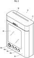
- Fig. 2 is a perspective rear view of the digital camera with a printer illustrated in Fig. 1 .
- the digital camera with a printer 10 includes a portable camera body 12.
- the camera body 12 has a small thickness in a forward-rearward direction and has a longitudinal rectangular parallelepiped shape of which a dimension in a longitudinal direction is longer than a dimension in a lateral direction.
- an imaging lens 14, a release button 16, an audio recording button 18, an electronic flash light emission window 20, and the like are comprised on a front surface side of the camera body 12.
- a power button 22a, a menu button 22b, an OK button 22c, a mode switching button 22d, a microphone hole 24, a speaker hole 26, and the like are comprised on a side surface on one side of the camera body 12.
- the release button 16 is a button for issuing an instruction to record an image.
- the power button 22a is a button for powering the digital camera with a printer 10 ON and OFF.
- the menu button 22b is a button for calling a menu screen.
- the OK button is a button for issuing an OK instruction.
- the mode switching button 22d is a button for switching between an auto print mode and a manual print mode in an imaging mode.
- a touch panel display 28, a film lid cover 30, and various types of operation buttons are comprised on a rear surface side of the camera body 12.
- the film lid cover 30 is a cover for opening and closing a film loading chamber.
- the types of operation buttons include a joystick 32a, a print button 32b, a play button 32c, a cancel button 32d, and the like.
- the print button 32b is a button for issuing an instruction to perform printing.
- the play button 32c is a button for issuing an instruction to switch to a playback mode.
- the cancel button 32d is a button for issuing an instruction to cancel an operation.
- a film discharge port 34 is comprised on an upper surface of the camera body 12. The instant film on which printing is performed is discharged from the film discharge port 34.
- the digital camera with a printer 10 comprises the film loading chamber (not illustrated), a film feeding mechanism 52, a film transport mechanism 54, a printhead 56, and the like as constituents of a printer part that is a print unit (refer to Fig. 5 ).
- An instant film pack having a structure in which a plurality of instant films is accommodated in a case is loaded into the film loading chamber.
- Fig. 3 is a front view of an instant film 42
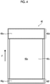
- Fig. 4 is a rear view of the instant film 42.
- a direction indicated by arrow F is a direction of use of the instant film 42, and the instant film 42 is transported in the direction indicated by arrow F. Accordingly, in a case where the instant film 42 is loaded into the digital camera with a printer 10, the direction indicated by arrow F is a discharge direction of the instant film 42.
- the instant film 42 is a self-developing instant film having a rectangular card shape.
- the instant film 42 is configured such that a rear surface side is an exposure surface 42a, and that a front surface side is an observation surface 42b.
- the exposure surface 42a is a surface on which an image is recorded by exposure.
- the observation surface 42b is a surface on which the recorded image is observed.
- an observation region 42h is comprised on the observation surface 42b of the instant film 42.
- an exposure region 42c, a pod portion 42d, and a trap portion 42f are comprised on the exposure surface 42a of the instant film 42.
- the instant film 42 is subjected to development treatment by spreading a development treatment liquid of the pod portion 42d onto the exposure region 42c after exposure.
- the pod portion 42d incorporates a development treatment liquid pod 42e containing the development treatment liquid.
- the development treatment liquid of the pod portion 42d is squeezed from the pod portion 42d and spread onto the exposure region 42c by passing the instant film 42 through a roller pair.
- the development treatment liquid that is left in spreading processing is trapped by the trap portion 42f.
- the trap portion 42f incorporates an absorbent material 42g.
- the instant film pack is loaded into the film loading chamber, not illustrated, that is disposed inside the camera body 12.
- the film is fed one sheet at a time by a claw (claw-shaped member), not illustrated, of the film feeding mechanism 52 and transported by a roller, not illustrated, of the film transport mechanism 54.
- the development treatment liquid is subjected to the spreading processing by pressing the pod portion 42d of the instant film 42 by a spreading roller pair, not illustrated.
- the printhead 56 is configured with a line exposure head and records the image on the instant film 42 in a single pass by irradiating the exposure surface 42a of the instant film 42, which is transported by the film transport mechanism 54, with print light one line at a time.
- a frame 42i is comprised around the observation region 42h, and the image is displayed inside the frame 42i.
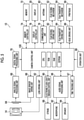
- Fig. 5 is a block diagram illustrating a main portion of an electric configuration of the digital camera with a printer.
- the digital camera with a printer 10 comprises the imaging lens 14, a lens driving unit 62, an image sensor 64, an image sensor driving unit 66, an analog signal processing unit 68, a digital signal processing unit 70, a memory 72, a memory controller 74, a display 28, a display controller 76, a communication unit 78, and an antenna 80.
- the digital camera with a printer 10 comprises a film feeding driving unit 82, a film transport driving unit 84, a head driving unit 86, a strobe 88, an electronic flash light emission control unit 90, a microphone 92, a speaker 94, an audio signal processing unit 96, a time tracking unit 97, an operation unit 98, and a camera control unit 100.
- the imaging lens 14 causes an optical image of a subject to be formed on a light-receiving surface of the image sensor 64.
- the imaging lens 14 has a focal point adjustment function and comprises, not illustrated, a stop and a shutter.
- the lens driving unit 62 includes a motor driving the focal point adjustment function of the imaging lens 14 and a driving circuit thereof, a motor driving the stop and a driving circuit thereof, and a motor driving the shutter and a driving circuit thereof, and operates a focal point adjustment mechanism, the stop, and the shutter in accordance with an instruction from the camera control unit 100.
- the image sensor 64 is configured with a two-dimensional solid-state imaging element such as a charge coupled device (CCD) image sensor or a complementary metal oxide semiconductor (CMOS) image sensor.
- the image sensor 64 has an imaging region of an aspect ratio corresponding to a printable region of the used instant film.
- the image sensor driving unit 66 includes a driving circuit of the image sensor 64 and operates the image sensor 64 in accordance with an instruction from the camera control unit 100.
- the imaging lens 14 and the image sensor 64 constitute an imaging unit.
- the analog signal processing unit 68 fetches an analog image signal of each pixel output from the image sensor 64, digitizes the analog image signal by performing signal processing (for example, correlative double sampling processing or amplification processing), and outputs the digitized image signal.
- signal processing for example, correlative double sampling processing or amplification processing
- the digital signal processing unit 70 fetches the digital image signal output from the analog signal processing unit 68 and generates image data by performing signal processing (for example, gradation transformation processing, white balance correction processing, gamma-correction processing, demosaicing processing, or YC transformation processing).
- signal processing for example, gradation transformation processing, white balance correction processing, gamma-correction processing, demosaicing processing, or YC transformation processing.
- the memory 72 is a non-temporary recording medium storing the image data obtained by imaging and audio data.
- a memory card is used as the memory 72.
- the memory 72 is an example of a storage unit.
- the memory controller 74 reads and writes data in the memory 72 under control of the camera control unit 100.
- the display 28 is configured with, for example, a liquid crystal display (LCD) or an organic electro-luminescence display (OELD). Besides, the display 28 may be configured with a plasma display, a field emission display (FED), an electronic paper, or the like.
- the display controller 76 displays a video on the display 28 under control of the camera control unit 100.
- the communication unit 78 wirelessly communicates with another digital camera with a printer 10 (another apparatus) through the antenna 80 under control of the camera control unit 100.
- the communication unit 78 can directly communicate with the other apparatus in a short range using short range wireless communication such as a near field communication (NFC) standard or Bluetooth (registered trademark).
- NFC near field communication
- Bluetooth registered trademark
- the communication unit 78 can connect to an information communication network such as the Internet through a Wi-Fi spot (Wi-Fi: registered trademark) and communicate with the other digital camera with a printer 10 (the other apparatus) regardless of distance.
- the film feeding driving unit 82 includes a motor driving the claw (claw-shaped member), not illustrated, of the film feeding mechanism 52 and a driving circuit thereof, and operates the claw by driving the motor under control of the camera control unit 100.
- the film transport driving unit 84 includes a motor driving a transport roller pair, not illustrated, of the film transport mechanism 54 and a driving circuit thereof and a motor driving the spreading roller pair, not illustrated, and a driving circuit thereof, and operates the transport roller pair and the spreading roller pair by driving the motor of the transport roller pair and the motor of the spreading roller pair under control of the camera control unit 100.
- the head driving unit 86 includes a driving circuit of the printhead 56 and drives the printhead 56 under control of the camera control unit 100.
- the strobe 88 comprises, for example, a xenon tube or a light emitting diode (LED) as a light source and irradiates the subject with electronic flash light by causing the light source to emit light. Irradiation with the electronic flash light is performed from the electronic flash light emission window 20 (refer to Fig. 1 ) comprised on a front surface of the camera body 12.
- the electronic flash light emission control unit 90 includes a driving circuit of the strobe 88 and causes the strobe 88 to emit light in accordance with an instruction from the camera control unit 100.
- the microphone 92 collects audio from an outside through the microphone hole 24 (refer to Fig. 2 ) comprised in the camera body 12.
- the microphone 92 is an example of an audio collection unit.
- the speaker 94 outputs audio to the outside from the speaker hole 26 comprised in the camera body 12.
- the audio signal processing unit 96 digitizes an audio signal input from the microphone 92 by performing signal processing and outputs the digitized audio signal.
- the audio signal processing unit 96 performs signal processing on audio data provided from the camera control unit 100 and outputs the audio data from the speaker 94.
- the time tracking unit 97 holds date and time information, and the camera control unit 100 sets an imaging time point (date and time) by referring to the information.
- the operation unit 98 includes various operation members such as the release button 16, the audio recording button 18, the power button 22a, the menu button 22b, the OK button 22c, the joystick 32a, the print button 32b, the play button 32c, and the cancel button 32d and a signal processing circuit thereof, and outputs a signal based on an operation of each operation member to the camera control unit 100.
- the camera control unit 100 is a control unit that controls an operation of the entire digital camera with a printer 10.
- the camera control unit 100 comprises a central processing unit (CPU), a read only memory (ROM), a random access memory (RAM), an electronically erasable and programmable read only memory (EEPROM), and the like.
- the camera control unit 100 is a computer configured with the CPU and the like and implements various functions described below by executing a control program.
- Fig. 6 is a diagram illustrating a functional configuration of the camera control unit 100.
- the camera control unit 100 comprises a communication control unit 100A (communication unit), an image composition unit 100B (image composition unit), an output control unit 100C (an information output unit, an output unit, and a composite image display unit), a print control unit 100D (print control unit), a storage control unit 100E (storage control unit), and a message processing unit 100F (output unit).
- a communication control unit 100A communication unit
- an image composition unit 100B image composition unit
- an output control unit 100C an information output unit, an output unit, and a composite image display unit
- a print control unit 100D print control unit
- storage control unit 100E storage control unit
- message processing unit 100F output unit
- a function of each unit of the camera control unit 100 described above can be implemented using various processors and a recording medium.
- the various processors include a CPU that is a general-purpose processor implementing various functions by executing software (program).
- the various processors include a graphics processing unit (GPU) that is a processor specialized in image processing, and a programmable logic device (PLD) such as a field programmable gate array (FPGA).
- the programmable logic device is a processor of which a circuit configuration can be changed after manufacturing. In a case of learning or recognizing images, a configuration using the GPU is effective.
- the various processors include a dedicated electric circuit or the like that is a processor such as an application specific integrated circuit (ASIC) having a circuit configuration dedicatedly designed to execute a specific type of processing.
- ASIC application specific integrated circuit
- each unit may be implemented by one processor or may be implemented by a plurality of processors of the same type or different types (for example, a plurality of FPGAs, a combination of a CPU and an FPGA, or a combination of a CPU and a GPU).
- one processor may have a plurality of functions.
- configuring the plurality of functions with one processor first, as represented by a computer, a form of configuring one processor with a combination of one or more CPUs and software and causing the processor to implement the plurality of functions is present.
- SoC system on chip
- various functions are configured using one or more of the various processors as a hardware structure.
- a hardware structure of those various processors is more specifically an electric circuit (circuitry) in which circuit elements such as semiconductor elements are combined.
- the electric circuit may be an electric circuit that implements the functions using a logical sum, a logical product, a logical negation, an exclusive logical sum, and a logical operation of a combination thereof.
- a code of the executed software readable by a computer (various processors or electric circuits constituting the camera control unit 100 and/or a combination thereof) is stored in a non-temporary recording medium such as a ROM, and the computer refers to the software.
- the software stored in the non-temporary recording medium includes a program for executing capturing and composition of images, and data used for execution.
- the non-temporary recording medium in which the code is recorded may be various magneto-optical recording devices, a semiconductor memory, and the like.
- a RAM is used as a temporary storage region.
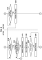
- Fig. 7 to Fig. 11 are flowcharts illustrating processing related to generation and the like of a composite image by the digital camera with a printer 10 having the above configuration.
- processing on a side hereinafter, referred to as a "host” requesting generation of the composite image is illustrated on a left side of the drawing, and processing on a side (hereinafter, referred to as a "client") receiving the composite image is illustrated on a right side of the drawing.
- Fig. 7 to Fig. 11 two digital cameras with a printer 10 having the above configuration are used.
- One digital camera with a printer 10 is used as the "host” (first digital camera with a printer), and the other digital camera with a printer 10 (second digital camera with a printer) is used as the "client".
- the digital cameras with a printer used as the host and the client do not necessarily have completely the same configuration. Digital cameras with a printer having different configurations may be used as the host and the client.
- the image composition unit 100B determines whether or not a request to generate the composite image is made (step S100). Whether or not the request is made can be determined by presence or absence of an operation of a user performed on the operation unit 98. In a case where the request to generate the composite image is made (YES in step S100), the image composition unit 100B selects a template of the composite image based on an instruction input of the user provided through the operation unit 98 (step S110).
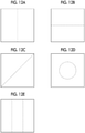
- Figs. 12A to 12E are diagrams illustrating examples of the template. In the examples illustrated in Figs.
- a boundary between an image (first image) captured by the host and an image (second image) captured by the client is illustrated by a dotted line.
- one image may be divided into left and right parts, upper and lower parts, or in an oblique manner or may be divided into a center portion and a periphery of the image.
- the number of divisions is not limited to two and may be three or more.
- the template may be decorated with a text, a number, a symbol, and the like in addition to the image.
- the image composition unit 100B generates, as the composite image, an image in which the first image and the second image are arranged in different regions of one image using the selected template.
- the image composition unit 100B may determine whether or not the request to generate the composite image is made based on a request on a client side.
- the client side may transmit a signal for requesting image composition with the second image to the host side, and the host side may start generating the composite image in response to the signal for requesting the image composition transmitted from the client side.
- the image composition unit 100B issues an imaging instruction for the first image (step S120).
- This imaging instruction can be issued by causing the image composition unit 100B to output a message prompting imaging to the speaker 94 or displaying the message on the display 28.
- the user can capture a desired image using the digital camera with a printer 10 that is an owned apparatus.
- the image composition unit 100B determines that the "first image is captured” (YES in step S130).
- the camera control unit 100 decides an imaging date and time of the image (first image) by referring to the information in the time tracking unit 97.
- the communication control unit 100A transmits the first image to the other apparatus (client) through the communication unit 78 (communication unit) and the antenna 80 (communication unit) and issues an imaging instruction for the second image (step S140).
- the image composition unit 100B and the communication control unit 100A can transmit the first image in a state where the first image is arranged in the template selected in step S110.
- the image composition unit 100B may cut the first image in accordance with the selected template.
- the communication control unit 100A (communication unit) can transmit the imaging instruction for the second image to the other apparatus through the communication unit 78 (communication unit) and the antenna 80 (communication unit).
- the digital camera with a printer 10 that is the client receives the first image and the imaging instruction for the second image by the communication unit 78 (communication unit) and the antenna 80 (communication unit) (step S300).
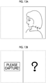
- the digital camera with a printer 10 (client) that receives the first image displays the received image (first image) on the display 28 (display unit) (step S305). Accordingly, the user can perceive "which image is composited with the image captured by the user".
- the output control unit 100C (the information output unit and the display unit) of the client outputs the imaging instruction for the second image by display on the display 28 (the information output unit and the display unit) and/or audio output from the speaker 94 (information output unit) (step S305).
- step S140 the host may not transmit the first image and transmit only the imaging instruction for the second image to the client.
- the output control unit 100C can display a question mark (information indicating that the first image is not received) on a right side (region in which the first image is arranged) of the image and display the imaging instruction on a left side (region in which the second image is arranged) of the image on the display 28 (step S305).
- the image composition unit 100B determines whether or not the second image is captured (step S310).
- the user can capture a desired image using the digital camera with a printer 10 as the client.
- the image is captured by the imaging lens 14, the image sensor 64, and the like (imaging unit)
- a positive determination is made in step S310.
- the camera control unit 100 decides the imaging time point (date and time) of the image (second image) captured by the client by referring to the information in the time tracking unit 97 in the same manner as described above for the first image.
- the communication control unit 100A (communication unit) on the client side transmits the second image to the host (the other apparatus) through the communication unit 78 (communication unit) and the antenna 80 (communication unit) (step S320).
- the output control unit 100C of the client may display the captured image (second image) on the display 28 before transmitting the captured image to the host.
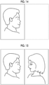
- the second image illustrated in Fig. 14 is captured.
- the communication control unit 100A determines whether or not the second image is received from the client (step S150). In a case where the second image is received (YES in step S150), the image composition unit 100B determines whether or not a difference between the imaging time point of the first image and the imaging time point of the second image is less than or equal to a threshold value (step S160). In a case where the difference between the imaging time points is greater than the threshold value (NO in step S160), the image composition unit 100B of the host does not generate the composite image, and returns to step S120 and issues the imaging instruction for the first image again.
- the image composition unit 100B of the host In a case where the difference between the imaging time points is less than or equal to the threshold value (YES in step S160), the image composition unit 100B of the host generates the composite image by compositing the first image and the second image (step S170).
- the image composition unit 100B In the examples described using Fig. 12A to Fig. 14 , the image composition unit 100B generates, as the composite image, an image in which the first image and the second image are arranged in different regions of one image in accordance with the selected template. At this point, the image composition unit 100B may cut the first image and/or the second image in accordance with the selected template.
- the image composition unit 100B displays the generated composite image on the display 28 (composite image display unit) (step S180).
- the user of the host can check the composite image.
- the composite image illustrated in Fig. 15 is generated and displayed.
- the host may return to step S120 or step S140 and perform processing again.
- the image composition unit 100B of the host may generate the composite image in which images of the host and all clients are arranged in one image, or may generate the composite image in which images of the host and a part (one or more) of the clients are arranged in one image.
- the digital camera with a printer 10 used by an actor can be used as the host, and a plurality of digital cameras with a printer 10 each used by an individual member of a fan club can be used as the clients.
- the image composition unit 100B of the host can generate an image (different images for each client) in which an image captured by the actor and an image of the individual member are composited.
- the message processing unit 100F determines whether or not to attach a message to the composite image (step S190).
- the message processing unit 100F can perform this determination based on an operation of the user performed through the operation unit 98.
- the message processing unit 100F displays information 530 for prompting audio recording of the message on the display 28 and generates, as "information indicating the message", audio that is input through the microphone 92 and the audio signal processing unit 96 in response to the display (step S200).
- the message processing unit 100F may output the information for prompting audio recording of the message from the speaker 94 or may perform audio recording in accordance with an operation performed on the audio recording button 18.
- a handwritten text, a symbol, or the like input through a touch panel of the display 28 may be generated as the "information indicating the message” and be attached to or superimposed on the image.
- the image composition unit 100B and the communication control unit 100A transmits the composite image generated in such a manner (in a case where the message is generated, the information indicating the message is associated with the composite image) to the client through the communication unit 78 (communication unit) and the antenna 80 (communication unit) (step S210).
- the communication control unit 100A receives the composite image (and the message) through the communication unit 78 (communication unit) and the antenna 80 (communication unit) (step S330) and displays the composite image on the display 28 (step S340).
- Fig. 17A is a diagram illustrating an example of the composite image to which an audio message is attached. A mark 600 of a speaker in the composite image indicates that the audio message is attached to the image.
- the message processing unit 100F of the client outputs information indicating that the message is attached, using the display 28 and/or the speaker 94.
- the message processing unit 100F outputs audio of the message by playing the audio through the audio signal processing unit 96 (output unit) and the speaker 94 (output unit) (step S360).
- the message processing unit 100F may display the message on the display 28 by superimposing the message on the composite image.
- the print control unit 100D may print the message such as the text or the symbol by superimposing the message on the composite image.
- the message may be generated and attached in a case where the host transmits the first image to the client, and/or in a case where the client transmits the second image to the host.
- Fig. 17B is an example of attaching the message in a case of transmitting the first image.
- Fig. 17C illustrates an example of generating the composite image in a state where the message is attached to both of the first image and the second image.
- the print control unit 100D determines whether or not the host is the digital camera with a printer 10 registered on an "automatic print permission list" (step S370). In a case where the host is registered on the list, the print control unit 100D causes the printer (configured with the printhead 56, the film feeding mechanism 52, the film transport mechanism 54, and the driving units thereof; refer to Fig. 5 ) of the owned apparatus to print the composite image independently of an instruction operation of the user (step S380).
- the print control unit 100D may determine whether or not to perform printing in accordance with an operation of the user (step S390) and perform printing in a case where a positive determination is made.
- the print control unit 100D can create the "automatic print permission list" based on individual identification information of the digital camera with a printer 10 or an operation of the user performed through the operation unit 98 and store the automatic print permission list in the EEPROM (refer to Fig. 5 ) of the camera control unit 100, and can refer to the automatic print permission list in a case of determination in step S370.
- the message processing unit 100F and the communication control unit 100A can upload the audio message to a storage device (server or the like) on a network through the communication unit 78 and the antenna 80 and acquire information (a two-dimensional barcode, a URL, or the like) indicating an upload destination.
- the print control unit 100D can print the information by superimposing the information on the composite image.
- Fig. 18 is an example illustrating a state where a two-dimensional barcode 610 indicating the upload destination of the message is displayed by superimposing the two-dimensional barcode 610 on the composite image. The user can read out the two-dimensional barcode using a smartphone or other apparatuses and an application and check the audio message by accessing the server or the like.
- the storage control unit 100E storage control unit of the client finishes processing without storing the composite image in the memory 72 (non-temporary recording medium). Accordingly, a rarity value of the printout can be increased, and printing can be promoted.
- the storage control unit 100E determines whether or not to store the composite image in the memory 72 (step S220).
- the storage control unit 100E can perform this determination based on an operation of the user performed through the operation unit 98 or the like.
- the storage control unit 100E stores the composite image in the memory 72 (step S230) and finishes processing.
- the host may transmit the composite image again in a case where a request is made from the client.
- the user can enjoy the composite image by capturing images using a plurality of cameras.
- the print control unit 100D may determine whether or not to print the composite image (step S212) and perform printing in a case where a positive determination is made (step S214).
- the print control unit 100D can determine whether or not to print the composite image based on an operation of the user performed through the operation unit 98.
- steps (steps S212 and S214) surrounded by a dash-dotted line are added with respect to the flowchart of Fig. 9 .
- the client may store the composite image.
- the storage control unit 100E storage control unit
- the storage control unit 100E can determine whether or not to store the composite image in the memory 72 (non-temporary recording medium) (step S392). In a case where a positive determination is made in step S392, the storage control unit 100E stores the composite image in the memory 72 (step S394). In a case where the message is attached to the composite image, it is preferable that the storage control unit 100E stores the composite image in association with the message.
- steps (steps S392 and S394) surrounded by a dash-dotted line are added with respect to the flowchart of Fig. 9 .
- processing on the host side is not illustrated.
- the image composition unit 100B may generate, as the composite image, an image in which the first image and the second image are superimposed.
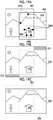
- Figs. 19A to 19C are diagrams for describing such generation of the composite image using superimposition. In the example illustrated in Fig.
- the image composition unit 100B of the host extracts a feature point 1000 from the image 501 as a corner portion of a subject 900 (house) and extracts a feature point 1010 from the image 502 as a corner portion or an intersection of a ridgeline of a subject 910 (mountain).
- the image composition unit 100B can generate the composite image by superimposing the image 501 and the image 502 such that the feature points 1000 and 1010 (feature points) extracted from the image 501 (first image) and the image 502 (second image) match.
- the image composition unit 100B can extract the feature points from the image 501 and the image 502 using a well-known method. In addition, in a case of superimposition, the image composition unit 100B may perform image processing such as movement, rotation, and deformation on the image 501 and/or the image 502.
- Fig. 19B illustrates an example of the composite image using superimposition.
- a composite image 510 of a panoramic image type is obtained, and an upper right region 511 and a lower left region 512 are blank (region in which image data is not present) due to deviation of the original images 501 and 502.
- a dotted line is a reference line indicating ranges of the original images 501 and 502.
- Fig. 19C illustrates another example of the composite image using superimposition.
- a composite image 520 of a panoramic image type is obtained.
- the image composition unit 100B trims an image region into a rectangular shape.
- a dotted line is a reference line indicating ranges of the original images 501 and 502.
- the image composition unit 100B may generate an image such as the composite image 510 or generate an image such as the composite image 520.
- the user of the digital camera with a printer 10 can enjoy the composite image by capturing images using a plurality of cameras.
- Fig. 9 An aspect in which the client automatically performs printing in a case where the client receives the composite image from the digital camera with a printer 10 registered on the "automatic print permission list" of the client is described using Fig. 9 .
- automatically performing printing by the client is not limited to a case where the composite image is received.
- the client may automatically print the image transmitted back from the host based on the "automatic print permission list".
- the client may automatically print the image transmitted back from the host.
Landscapes
- Engineering & Computer Science (AREA)
- Multimedia (AREA)
- Signal Processing (AREA)
- Computing Systems (AREA)
- Theoretical Computer Science (AREA)
- Human Computer Interaction (AREA)
- General Physics & Mathematics (AREA)
- General Engineering & Computer Science (AREA)
- Automation & Control Theory (AREA)
- Physics & Mathematics (AREA)
- Studio Devices (AREA)
- Cameras Adapted For Combination With Other Photographic Or Optical Apparatuses (AREA)
- Television Signal Processing For Recording (AREA)
- Accessory Devices And Overall Control Thereof (AREA)
- Record Information Processing For Printing (AREA)
Abstract
Description
- The present invention relates to a digital camera with a printer.
- In recent years, a digital camera with a printer capable of instantly printing a captured image has been widely used, and various methods of use have been suggested. For example,
JP2002-112152A - In the technology disclosed in
JP2002-112152A - The present invention is conceived in view of such a matter, and an object thereof is to provide a digital camera with a printer enabling a composite image to be enjoyed by capturing images using a plurality of cameras.
- In order to accomplish the above object, a digital camera with a printer according to a first aspect of the present invention is a digital camera with a printer and comprises a communication unit that communicates with a digital camera with a printer of another apparatus as a client, and an image composition unit that generates a composite image in which a first image captured by the digital camera with a printer of an owned apparatus as a host and a second image captured by the client are composited, in which the communication unit transmits the composite image to the client.
- In the first aspect, the composite image in which the image captured by the owned apparatus as the host (side on which the composite image is generated) and the image captured by the other apparatus as the client (side on which the composite image is received) are composited is generated, and the generated composite image is transmitted to the client (the other apparatus). Thus, not only a user of the host (owned apparatus) but also a user of the client (the other apparatus) can obtain the composite image. Accordingly, the composite image can be enjoyed by capturing images using a plurality of cameras. In a case where a plurality of digital cameras according to the first aspect are present, each digital camera can be the host or the client. In addition, the number of digital cameras on the side (client) on which the composite image is received may be one or plural.
- The digital camera with a printer according to a second aspect is the digital camera with a printer of the first aspect, in which the image composition unit generates, as the composite image, an image in which the first image and the second image are arranged in different regions of one image. The second aspect prescribes an aspect of the composite image. Shapes and sizes of regions in which the first image and the second image are arranged may be selectable by the user.
- The digital camera with a printer according to a third aspect is the digital camera with a printer of the first aspect, in which the image composition unit generates, as the composite image, an image in which the first image and the second image are superimposed. The third aspect prescribes another aspect of the composite image.
- The digital camera with a printer according to a fourth aspect is the digital camera with a printer of the third aspect, in which the image composition unit superimposes the first image and the second image based on feature points extracted from the first image and the second image. The fourth aspect prescribes an aspect of an image composition method using superimposition.
- The digital camera with a printer according to a fifth aspect is the digital camera with a printer of any one of the first to fourth aspects, in which the image composition unit generates the composite image in a case where a difference between an imaging time point of the first image and an imaging time point of the second image is less than or equal to a threshold value. According to the fifth aspect, the composite image can be generated using images of which imaging timings are aligned. The threshold value for the imaging time points may be changeable by the user.
- The digital camera with a printer according to a sixth aspect is the digital camera with a printer of any one of the first to fifth aspects, further comprising a display unit that displays the first image received from the host, in which the communication unit transmits the second image to the host. According to the sixth aspect, the user of the client can check the image (first image) captured by the host.
- The digital camera with a printer according to a seventh aspect is the digital camera with a printer of any one of the first to sixth aspects, in which the communication unit transmits information for prompting capturing of the second image to the client. According to the seventh aspect, by transmitting the information for prompting capturing of the second image to the client from the host, the imaging timings can be easily aligned. The information for prompting capturing may be audio or a text. In addition, the information for prompting capturing may be information for causing a light emitting element to emit light.
- The digital camera with a printer according to an eighth aspect is the digital camera with a printer of the seventh aspect, further comprising an information output unit that outputs the information for prompting capturing of the second image. According to the eighth aspect, the imaging timings can be easily aligned among a plurality of users. The information output unit can output information using audio, a text, light emission of a light emitting element, and the like.
- The digital camera with a printer according to a ninth aspect is the digital camera with a printer of the eighth aspect, in which the communication unit transmits an image captured in accordance with the information received from the host to the host as the second image. According to the ninth aspect, the digital camera with a printer as the host (side on which the composite image is generated) can acquire an image necessary for generating the composite image from the client.
- The digital camera with a printer according to a tenth aspect is the digital camera with a printer of any one of the first to ninth aspects, further comprising a print control unit that controls printing of the composite image, in which in a case where the composite image is received from the host, the print control unit causes a printer of the owned apparatus which is the client to print the composite image independently of an instruction operation of a user. According to the tenth aspect, the client can automatically print the composite image.
- The digital camera with a printer according to an eleventh aspect is the digital camera with a printer of the tenth aspect, in which in a case where the host is a digital camera with a printer registered on an automatic print permission list, the print control unit causes the printer of the owned apparatus which is the client to print the composite image independently of the instruction operation of the user. According to the eleventh aspect, unintended automatic printing in the client can be prevented.
- The digital camera with a printer according to a twelfth aspect is the digital camera with a printer of any one of the first to eleventh aspects, further comprising a storage control unit that controls storage of an image in a recording medium, in which the storage control unit does not store the composite image in a non-temporary recording medium. According to the twelfth aspect, since the composite image is not stored in the non-temporary recording medium (recording medium such as a memory card in which data is not deleted even in a case where power is off), it is possible to prompt the user to perform printing. In addition, rarity of the printed composite image can be increased. In the tenth aspect, the image may be temporarily stored in a recording medium such as a random access memory (RAM) for displaying or printing the composite image.
- The digital camera with a printer according to a thirteenth aspect is the digital camera with a printer of any one of the first to eleventh aspects, further comprising a storage control unit that controls storage of an image in a recording medium, in which the storage control unit stores the composite image in a non-temporary recording medium. According to the thirteenth aspect, the composite image can be stored.
- The digital camera with a printer according to a fourteenth aspect is the digital camera with a printer of any one of the first to thirteenth aspects, in which the communication unit transmits information indicating a message to the client by associating the information with the composite image. The information indicating the message may be data of a text, audio, or the like or may be information such as a uniform resource locator (URL) indicating a location at which data of a text, audio, or the like is stored.
- The digital camera with a printer according to a fifteenth aspect is the digital camera with a printer of any one of the first to fourteenth aspects, further comprising an output unit that outputs the message based on the information indicating the message. In a case where information such as audio or an image is directly associated with the composite image, the message can be output. In a case where information such as the URL indicating a location of audio, an image, or the like is associated, the message acquired by accessing a server or the like can be output. According to the fifteenth aspect, the user can enjoy a message of another user who creates the composite image.
- The digital camera with a printer according to a sixteenth aspect is the digital camera with a printer of any one of the first to fifteenth aspects, further comprising a composite image display unit that displays the composite image. According to the sixteenth aspect, the composite image can be visually recognized.
- The digital camera with a printer according to a seventeenth aspect is the digital camera with a printer of any one of the first to sixteenth aspects, in which the communication unit communicates with the digital camera with a printer which is the other apparatus using short range wireless communication. According to the seventeenth aspect, transmission and reception of images and generation and printing of the composite image can be directly enjoyed between nearby users.
- The digital camera with a printer according to an eighteenth aspect is the digital camera with a printer of any one of the first to seventeenth aspects, in which the communication unit communicates with the digital camera with a printer which is the other apparatus through an information communication network. According to the eighteenth aspect, transmission and reception of images and generation and printing of the composite image can be enjoyed between users far from each other through the information communication network such as the Internet.
- As described above, according to the digital camera with a printer according to an aspect of the present invention, the composite image can be enjoyed by capturing images using a plurality of cameras.
-
-
Fig. 1 is a perspective front view illustrating a digital camera with a printer. -
Fig. 2 is a perspective rear view illustrating the digital camera with a printer. -
Fig. 3 is a front view of an instant film. -
Fig. 4 is a rear view of the instant film. -
Fig. 5 is a diagram illustrating an electric configuration of the digital camera with a printer. -
Fig. 6 is a function block diagram of a camera control unit. -
Fig. 7 is a flowchart illustrating a procedure of processing related to image composition. -
Fig. 8 is another flowchart illustrating the procedure of processing related to the image composition. -
Fig. 9 is still another flowchart illustrating the procedure of processing related to the image composition. -
Fig. 10 is a flowchart illustrating a modification example of the procedure of processing related to the image composition. -
Fig. 11 is another flowchart illustrating the modification example of the procedure of processing related to the image composition. -
Figs. 12 Ato12E are diagrams illustrating patterns of the image composition. -
Figs. 13A and 13B are diagrams illustrating examples of a first image. -
Fig. 14 is a diagram illustrating an example of a second image. -
Fig. 15 is a diagram illustrating an example of a composite image. -
Fig. 16 is a diagram illustrating a state of attaching a message to an image. -
Figs. 17A to 17C are diagrams illustrating examples of an image to which an audio message is attached. -
Fig. 18 is a diagram illustrating an example of a composite image on which a two-dimensional barcode indicating an audio message is superimposed. -
Figs. 19A to 19C are diagrams illustrating an example of image composition using superimposition. - An embodiment of a digital camera with a printer according to the present invention will be described in detail below. In description, the appended drawings will be referred to.
- A digital camera with a
printer 10 is a digital camera incorporating a printer and has a function of instantly printing a captured image. The digital camera with aprinter 10 of the present embodiment performs printing on an instant film using an instant film pack. In addition, the digital camera with aprinter 10 of the present embodiment has an audio recording function and can record audio in association with the captured image. -
Fig. 1 is a perspective front view illustrating an example of the digital camera with a printer.Fig. 2 is a perspective rear view of the digital camera with a printer illustrated inFig. 1 . - As illustrated in
Fig. 1 andFig. 2 , the digital camera with aprinter 10 includes aportable camera body 12. Thecamera body 12 has a small thickness in a forward-rearward direction and has a longitudinal rectangular parallelepiped shape of which a dimension in a longitudinal direction is longer than a dimension in a lateral direction. - As illustrated in
Fig. 1 , animaging lens 14, arelease button 16, anaudio recording button 18, an electronic flashlight emission window 20, and the like are comprised on a front surface side of thecamera body 12. In addition, apower button 22a, amenu button 22b, anOK button 22c, amode switching button 22d, amicrophone hole 24, aspeaker hole 26, and the like are comprised on a side surface on one side of thecamera body 12. Therelease button 16 is a button for issuing an instruction to record an image. Thepower button 22a is a button for powering the digital camera with aprinter 10 ON and OFF. Themenu button 22b is a button for calling a menu screen. The OK button is a button for issuing an OK instruction. Themode switching button 22d is a button for switching between an auto print mode and a manual print mode in an imaging mode. - As illustrated in
Fig. 2 , atouch panel display 28, afilm lid cover 30, and various types of operation buttons are comprised on a rear surface side of thecamera body 12. Thefilm lid cover 30 is a cover for opening and closing a film loading chamber. The types of operation buttons include ajoystick 32a, aprint button 32b, aplay button 32c, a cancelbutton 32d, and the like. Theprint button 32b is a button for issuing an instruction to perform printing. Theplay button 32c is a button for issuing an instruction to switch to a playback mode. The cancelbutton 32d is a button for issuing an instruction to cancel an operation. - As illustrated in
Fig. 1 andFig. 2 , afilm discharge port 34 is comprised on an upper surface of thecamera body 12. The instant film on which printing is performed is discharged from thefilm discharge port 34. - The digital camera with a
printer 10 comprises the film loading chamber (not illustrated), afilm feeding mechanism 52, afilm transport mechanism 54, aprinthead 56, and the like as constituents of a printer part that is a print unit (refer toFig. 5 ). An instant film pack having a structure in which a plurality of instant films is accommodated in a case is loaded into the film loading chamber.Fig. 3 is a front view of aninstant film 42, andFig. 4 is a rear view of theinstant film 42. InFig. 3 andFig. 4 , a direction indicated by arrow F is a direction of use of theinstant film 42, and theinstant film 42 is transported in the direction indicated by arrow F. Accordingly, in a case where theinstant film 42 is loaded into the digital camera with aprinter 10, the direction indicated by arrow F is a discharge direction of theinstant film 42. - The
instant film 42 is a self-developing instant film having a rectangular card shape. Theinstant film 42 is configured such that a rear surface side is anexposure surface 42a, and that a front surface side is anobservation surface 42b. Theexposure surface 42a is a surface on which an image is recorded by exposure. Theobservation surface 42b is a surface on which the recorded image is observed. - As illustrated in
Fig. 3 , anobservation region 42h is comprised on theobservation surface 42b of theinstant film 42. In addition, as illustrated inFig. 4 , anexposure region 42c, apod portion 42d, and atrap portion 42f are comprised on theexposure surface 42a of theinstant film 42. Theinstant film 42 is subjected to development treatment by spreading a development treatment liquid of thepod portion 42d onto theexposure region 42c after exposure. Thepod portion 42d incorporates a developmenttreatment liquid pod 42e containing the development treatment liquid. The development treatment liquid of thepod portion 42d is squeezed from thepod portion 42d and spread onto theexposure region 42c by passing theinstant film 42 through a roller pair. The development treatment liquid that is left in spreading processing is trapped by thetrap portion 42f. Thetrap portion 42f incorporates anabsorbent material 42g. - The instant film pack is loaded into the film loading chamber, not illustrated, that is disposed inside the
camera body 12. In a case of printing, the film is fed one sheet at a time by a claw (claw-shaped member), not illustrated, of thefilm feeding mechanism 52 and transported by a roller, not illustrated, of thefilm transport mechanism 54. In addition, during transport, the development treatment liquid is subjected to the spreading processing by pressing thepod portion 42d of theinstant film 42 by a spreading roller pair, not illustrated. Theprinthead 56 is configured with a line exposure head and records the image on theinstant film 42 in a single pass by irradiating theexposure surface 42a of theinstant film 42, which is transported by thefilm transport mechanism 54, with print light one line at a time. Aframe 42i is comprised around theobservation region 42h, and the image is displayed inside theframe 42i. -
Fig. 5 is a block diagram illustrating a main portion of an electric configuration of the digital camera with a printer. - As illustrated in the drawing, the digital camera with a
printer 10 comprises theimaging lens 14, alens driving unit 62, animage sensor 64, an imagesensor driving unit 66, an analogsignal processing unit 68, a digitalsignal processing unit 70, amemory 72, amemory controller 74, adisplay 28, adisplay controller 76, acommunication unit 78, and anantenna 80. In addition, the digital camera with aprinter 10 comprises a filmfeeding driving unit 82, a filmtransport driving unit 84, ahead driving unit 86, astrobe 88, an electronic flash lightemission control unit 90, amicrophone 92, aspeaker 94, an audiosignal processing unit 96, atime tracking unit 97, anoperation unit 98, and acamera control unit 100. - The
imaging lens 14 causes an optical image of a subject to be formed on a light-receiving surface of theimage sensor 64. Theimaging lens 14 has a focal point adjustment function and comprises, not illustrated, a stop and a shutter. Thelens driving unit 62 includes a motor driving the focal point adjustment function of theimaging lens 14 and a driving circuit thereof, a motor driving the stop and a driving circuit thereof, and a motor driving the shutter and a driving circuit thereof, and operates a focal point adjustment mechanism, the stop, and the shutter in accordance with an instruction from thecamera control unit 100. - The
image sensor 64 is configured with a two-dimensional solid-state imaging element such as a charge coupled device (CCD) image sensor or a complementary metal oxide semiconductor (CMOS) image sensor. Theimage sensor 64 has an imaging region of an aspect ratio corresponding to a printable region of the used instant film. The imagesensor driving unit 66 includes a driving circuit of theimage sensor 64 and operates theimage sensor 64 in accordance with an instruction from thecamera control unit 100. - In the digital camera with a
printer 10 of the present embodiment, theimaging lens 14 and theimage sensor 64 constitute an imaging unit. - The analog
signal processing unit 68 fetches an analog image signal of each pixel output from theimage sensor 64, digitizes the analog image signal by performing signal processing (for example, correlative double sampling processing or amplification processing), and outputs the digitized image signal. - The digital
signal processing unit 70 fetches the digital image signal output from the analogsignal processing unit 68 and generates image data by performing signal processing (for example, gradation transformation processing, white balance correction processing, gamma-correction processing, demosaicing processing, or YC transformation processing). - The
memory 72 is a non-temporary recording medium storing the image data obtained by imaging and audio data. For example, a memory card is used as thememory 72. Thememory 72 is an example of a storage unit. Thememory controller 74 reads and writes data in thememory 72 under control of thecamera control unit 100. - The
display 28 is configured with, for example, a liquid crystal display (LCD) or an organic electro-luminescence display (OELD). Besides, thedisplay 28 may be configured with a plasma display, a field emission display (FED), an electronic paper, or the like. Thedisplay controller 76 displays a video on thedisplay 28 under control of thecamera control unit 100. - The
communication unit 78 wirelessly communicates with another digital camera with a printer 10 (another apparatus) through theantenna 80 under control of thecamera control unit 100. Thecommunication unit 78 can directly communicate with the other apparatus in a short range using short range wireless communication such as a near field communication (NFC) standard or Bluetooth (registered trademark). In addition, thecommunication unit 78 can connect to an information communication network such as the Internet through a Wi-Fi spot (Wi-Fi: registered trademark) and communicate with the other digital camera with a printer 10 (the other apparatus) regardless of distance. - The film
feeding driving unit 82 includes a motor driving the claw (claw-shaped member), not illustrated, of thefilm feeding mechanism 52 and a driving circuit thereof, and operates the claw by driving the motor under control of thecamera control unit 100. - The film
transport driving unit 84 includes a motor driving a transport roller pair, not illustrated, of thefilm transport mechanism 54 and a driving circuit thereof and a motor driving the spreading roller pair, not illustrated, and a driving circuit thereof, and operates the transport roller pair and the spreading roller pair by driving the motor of the transport roller pair and the motor of the spreading roller pair under control of thecamera control unit 100. - The
head driving unit 86 includes a driving circuit of theprinthead 56 and drives theprinthead 56 under control of thecamera control unit 100. - The
strobe 88 comprises, for example, a xenon tube or a light emitting diode (LED) as a light source and irradiates the subject with electronic flash light by causing the light source to emit light. Irradiation with the electronic flash light is performed from the electronic flash light emission window 20 (refer toFig. 1 ) comprised on a front surface of thecamera body 12. The electronic flash lightemission control unit 90 includes a driving circuit of thestrobe 88 and causes thestrobe 88 to emit light in accordance with an instruction from thecamera control unit 100. - The
microphone 92 collects audio from an outside through the microphone hole 24 (refer toFig. 2 ) comprised in thecamera body 12. Themicrophone 92 is an example of an audio collection unit. Thespeaker 94 outputs audio to the outside from thespeaker hole 26 comprised in thecamera body 12. The audiosignal processing unit 96 digitizes an audio signal input from themicrophone 92 by performing signal processing and outputs the digitized audio signal. In addition, the audiosignal processing unit 96 performs signal processing on audio data provided from thecamera control unit 100 and outputs the audio data from thespeaker 94. Thetime tracking unit 97 holds date and time information, and thecamera control unit 100 sets an imaging time point (date and time) by referring to the information. - The
operation unit 98 includes various operation members such as therelease button 16, theaudio recording button 18, thepower button 22a, themenu button 22b, theOK button 22c, thejoystick 32a, theprint button 32b, theplay button 32c, and the cancelbutton 32d and a signal processing circuit thereof, and outputs a signal based on an operation of each operation member to thecamera control unit 100. - The
camera control unit 100 is a control unit that controls an operation of the entire digital camera with aprinter 10. Thecamera control unit 100 comprises a central processing unit (CPU), a read only memory (ROM), a random access memory (RAM), an electronically erasable and programmable read only memory (EEPROM), and the like. Thecamera control unit 100 is a computer configured with the CPU and the like and implements various functions described below by executing a control program. -
Fig. 6 is a diagram illustrating a functional configuration of thecamera control unit 100. Thecamera control unit 100 comprises acommunication control unit 100A (communication unit), animage composition unit 100B (image composition unit), anoutput control unit 100C (an information output unit, an output unit, and a composite image display unit), aprint control unit 100D (print control unit), astorage control unit 100E (storage control unit), and amessage processing unit 100F (output unit). - A function of each unit of the
camera control unit 100 described above can be implemented using various processors and a recording medium. For example, the various processors include a CPU that is a general-purpose processor implementing various functions by executing software (program). In addition, the various processors include a graphics processing unit (GPU) that is a processor specialized in image processing, and a programmable logic device (PLD) such as a field programmable gate array (FPGA). The programmable logic device is a processor of which a circuit configuration can be changed after manufacturing. In a case of learning or recognizing images, a configuration using the GPU is effective. Furthermore, the various processors include a dedicated electric circuit or the like that is a processor such as an application specific integrated circuit (ASIC) having a circuit configuration dedicatedly designed to execute a specific type of processing. - The function of each unit may be implemented by one processor or may be implemented by a plurality of processors of the same type or different types (for example, a plurality of FPGAs, a combination of a CPU and an FPGA, or a combination of a CPU and a GPU). In addition, one processor may have a plurality of functions. As an example of configuring the plurality of functions with one processor, first, as represented by a computer, a form of configuring one processor with a combination of one or more CPUs and software and causing the processor to implement the plurality of functions is present. Second, as represented by a system on chip (SoC) or the like, a form of using a processor that implements a function of the entire system using one integrated circuit (IC) chip is present. In such a manner, various functions are configured using one or more of the various processors as a hardware structure. Furthermore, a hardware structure of those various processors is more specifically an electric circuit (circuitry) in which circuit elements such as semiconductor elements are combined. The electric circuit may be an electric circuit that implements the functions using a logical sum, a logical product, a logical negation, an exclusive logical sum, and a logical operation of a combination thereof.
- In a case where the processor or the electric circuit executes software (program), a code of the executed software readable by a computer (various processors or electric circuits constituting the
camera control unit 100 and/or a combination thereof) is stored in a non-temporary recording medium such as a ROM, and the computer refers to the software. The software stored in the non-temporary recording medium includes a program for executing capturing and composition of images, and data used for execution. Instead of the ROM, the non-temporary recording medium in which the code is recorded may be various magneto-optical recording devices, a semiconductor memory, and the like. In a case of processing using the software, for example, a RAM is used as a temporary storage region. -
Fig. 7 to Fig. 11 are flowcharts illustrating processing related to generation and the like of a composite image by the digital camera with aprinter 10 having the above configuration. InFig. 7 to Fig. 11 , processing on a side (hereinafter, referred to as a "host") requesting generation of the composite image is illustrated on a left side of the drawing, and processing on a side (hereinafter, referred to as a "client") receiving the composite image is illustrated on a right side of the drawing. InFig. 7 to Fig. 11 , two digital cameras with aprinter 10 having the above configuration are used. One digital camera with aprinter 10 is used as the "host" (first digital camera with a printer), and the other digital camera with a printer 10 (second digital camera with a printer) is used as the "client". The digital cameras with a printer used as the host and the client do not necessarily have completely the same configuration. Digital cameras with a printer having different configurations may be used as the host and the client. - In the digital camera with a
printer 10 on a host side, theimage composition unit 100B determines whether or not a request to generate the composite image is made (step S100). Whether or not the request is made can be determined by presence or absence of an operation of a user performed on theoperation unit 98. In a case where the request to generate the composite image is made (YES in step S100), theimage composition unit 100B selects a template of the composite image based on an instruction input of the user provided through the operation unit 98 (step S110).Figs. 12A to 12E are diagrams illustrating examples of the template. In the examples illustrated inFigs. 12 Ato12E , a boundary between an image (first image) captured by the host and an image (second image) captured by the client is illustrated by a dotted line. As illustrated in the examples, in the template, one image may be divided into left and right parts, upper and lower parts, or in an oblique manner or may be divided into a center portion and a periphery of the image. In addition, the number of divisions is not limited to two and may be three or more. Furthermore, the template may be decorated with a text, a number, a symbol, and the like in addition to the image. Theimage composition unit 100B generates, as the composite image, an image in which the first image and the second image are arranged in different regions of one image using the selected template. Theimage composition unit 100B may determine whether or not the request to generate the composite image is made based on a request on a client side. In this case, the client side may transmit a signal for requesting image composition with the second image to the host side, and the host side may start generating the composite image in response to the signal for requesting the image composition transmitted from the client side. - In a case where the template is selected, the
image composition unit 100B issues an imaging instruction for the first image (step S120). This imaging instruction can be issued by causing theimage composition unit 100B to output a message prompting imaging to thespeaker 94 or displaying the message on thedisplay 28. The user can capture a desired image using the digital camera with aprinter 10 that is an owned apparatus. In a case where an image is captured by theimaging lens 14, theimage sensor 64, and the like (imaging unit), theimage composition unit 100B determines that the "first image is captured" (YES in step S130). Thecamera control unit 100 decides an imaging date and time of the image (first image) by referring to the information in thetime tracking unit 97. - In a case where the first image is captured, the
communication control unit 100A (communication unit) transmits the first image to the other apparatus (client) through the communication unit 78 (communication unit) and the antenna 80 (communication unit) and issues an imaging instruction for the second image (step S140). As illustrated inFig. 13A , theimage composition unit 100B and thecommunication control unit 100A can transmit the first image in a state where the first image is arranged in the template selected in step S110. At this point, theimage composition unit 100B may cut the first image in accordance with the selected template. In addition, thecommunication control unit 100A (communication unit) can transmit the imaging instruction for the second image to the other apparatus through the communication unit 78 (communication unit) and the antenna 80 (communication unit). - The digital camera with a
printer 10 that is the client receives the first image and the imaging instruction for the second image by the communication unit 78 (communication unit) and the antenna 80 (communication unit) (step S300). The digital camera with a printer 10 (client) that receives the first image displays the received image (first image) on the display 28 (display unit) (step S305). Accordingly, the user can perceive "which image is composited with the image captured by the user". In addition, theoutput control unit 100C (the information output unit and the display unit) of the client outputs the imaging instruction for the second image by display on the display 28 (the information output unit and the display unit) and/or audio output from the speaker 94 (information output unit) (step S305). - In step S140, the host may not transmit the first image and transmit only the imaging instruction for the second image to the client. In this case, in the client, as illustrated in
Fig. 13B , theoutput control unit 100C can display a question mark (information indicating that the first image is not received) on a right side (region in which the first image is arranged) of the image and display the imaging instruction on a left side (region in which the second image is arranged) of the image on the display 28 (step S305). - In the client, the
image composition unit 100B determines whether or not the second image is captured (step S310). The user can capture a desired image using the digital camera with aprinter 10 as the client. In a case where the image is captured by theimaging lens 14, theimage sensor 64, and the like (imaging unit), a positive determination is made in step S310. In a case of imaging, thecamera control unit 100 decides the imaging time point (date and time) of the image (second image) captured by the client by referring to the information in thetime tracking unit 97 in the same manner as described above for the first image. Thecommunication control unit 100A (communication unit) on the client side transmits the second image to the host (the other apparatus) through the communication unit 78 (communication unit) and the antenna 80 (communication unit) (step S320). Theoutput control unit 100C of the client may display the captured image (second image) on thedisplay 28 before transmitting the captured image to the host. Here, it is assumed that the second image illustrated inFig. 14 is captured. - In the host, the
communication control unit 100A determines whether or not the second image is received from the client (step S150). In a case where the second image is received (YES in step S150), theimage composition unit 100B determines whether or not a difference between the imaging time point of the first image and the imaging time point of the second image is less than or equal to a threshold value (step S160). In a case where the difference between the imaging time points is greater than the threshold value (NO in step S160), theimage composition unit 100B of the host does not generate the composite image, and returns to step S120 and issues the imaging instruction for the first image again. - In a case where the difference between the imaging time points is less than or equal to the threshold value (YES in step S160), the
image composition unit 100B of the host generates the composite image by compositing the first image and the second image (step S170). In the examples described usingFig. 12A toFig. 14 , theimage composition unit 100B generates, as the composite image, an image in which the first image and the second image are arranged in different regions of one image in accordance with the selected template. At this point, theimage composition unit 100B may cut the first image and/or the second image in accordance with the selected template. In addition, theimage composition unit 100B displays the generated composite image on the display 28 (composite image display unit) (step S180). Accordingly, the user of the host can check the composite image. Here, it is assumed that the composite image illustrated inFig. 15 is generated and displayed. In a case where the user of the host is not satisfied with the composite image (for example, in a case where the user issues an instruction to perform processing again through the operation unit 98), the host may return to step S120 or step S140 and perform processing again. - In the processing related to generation of the composite image, a plurality of clients may be present instead of one client. In a case where a plurality of clients are present, the
image composition unit 100B of the host may generate the composite image in which images of the host and all clients are arranged in one image, or may generate the composite image in which images of the host and a part (one or more) of the clients are arranged in one image. For example, the digital camera with aprinter 10 used by an actor can be used as the host, and a plurality of digital cameras with aprinter 10 each used by an individual member of a fan club can be used as the clients. In this case, for example, theimage composition unit 100B of the host can generate an image (different images for each client) in which an image captured by the actor and an image of the individual member are composited. - In the host, the
message processing unit 100F determines whether or not to attach a message to the composite image (step S190). Themessage processing unit 100F can perform this determination based on an operation of the user performed through theoperation unit 98. In a case of attaching the message to the composite image (YES in step S190), for example, as in the example inFig. 16 , themessage processing unit 100F displaysinformation 530 for prompting audio recording of the message on thedisplay 28 and generates, as "information indicating the message", audio that is input through themicrophone 92 and the audiosignal processing unit 96 in response to the display (step S200). Themessage processing unit 100F may output the information for prompting audio recording of the message from thespeaker 94 or may perform audio recording in accordance with an operation performed on theaudio recording button 18. A handwritten text, a symbol, or the like input through a touch panel of thedisplay 28 may be generated as the "information indicating the message" and be attached to or superimposed on the image. - In the host, the
image composition unit 100B and thecommunication control unit 100A (communication unit) transmits the composite image generated in such a manner (in a case where the message is generated, the information indicating the message is associated with the composite image) to the client through the communication unit 78 (communication unit) and the antenna 80 (communication unit) (step S210). In the client, thecommunication control unit 100A (communication unit) receives the composite image (and the message) through the communication unit 78 (communication unit) and the antenna 80 (communication unit) (step S330) and displays the composite image on the display 28 (step S340).Fig. 17A is a diagram illustrating an example of the composite image to which an audio message is attached. Amark 600 of a speaker in the composite image indicates that the audio message is attached to the image. - In a case where the message is attached (YES in step S350), the
message processing unit 100F of the client outputs information indicating that the message is attached, using thedisplay 28 and/or thespeaker 94. In a case where the user of the client issues an instruction to output the message by performing an operation through theoperation unit 98 or themicrophone 92, themessage processing unit 100F (output unit) outputs audio of the message by playing the audio through the audio signal processing unit 96 (output unit) and the speaker 94 (output unit) (step S360). In a case where the handwritten text, the symbol, or the like is attached as the message, themessage processing unit 100F (output unit) may display the message on thedisplay 28 by superimposing the message on the composite image. In addition, theprint control unit 100D may print the message such as the text or the symbol by superimposing the message on the composite image. - While a case where the host attaches the message to the composite image is described in the above aspect, the message may be generated and attached in a case where the host transmits the first image to the client, and/or in a case where the client transmits the second image to the host.
Fig. 17B is an example of attaching the message in a case of transmitting the first image.Fig. 17C illustrates an example of generating the composite image in a state where the message is attached to both of the first image and the second image. - In the client that receives the composite image from the host, the
print control unit 100D (print control unit) determines whether or not the host is the digital camera with aprinter 10 registered on an "automatic print permission list" (step S370). In a case where the host is registered on the list, theprint control unit 100D causes the printer (configured with theprinthead 56, thefilm feeding mechanism 52, thefilm transport mechanism 54, and the driving units thereof; refer toFig. 5 ) of the owned apparatus to print the composite image independently of an instruction operation of the user (step S380). In addition, even in a case where the composite image is received from the host not registered on the "automatic print permission list", theprint control unit 100D may determine whether or not to perform printing in accordance with an operation of the user (step S390) and perform printing in a case where a positive determination is made. For example, theprint control unit 100D can create the "automatic print permission list" based on individual identification information of the digital camera with aprinter 10 or an operation of the user performed through theoperation unit 98 and store the automatic print permission list in the EEPROM (refer toFig. 5 ) of thecamera control unit 100, and can refer to the automatic print permission list in a case of determination in step S370. - In a case where the composite image is printed, the user cannot refer to the audio message associated with the composite image from a printout. In this case, in a case of printing the composite image to which the audio message is attached, the
message processing unit 100F and thecommunication control unit 100A can upload the audio message to a storage device (server or the like) on a network through thecommunication unit 78 and theantenna 80 and acquire information (a two-dimensional barcode, a URL, or the like) indicating an upload destination. Theprint control unit 100D can print the information by superimposing the information on the composite image.Fig. 18 is an example illustrating a state where a two-dimensional barcode 610 indicating the upload destination of the message is displayed by superimposing the two-dimensional barcode 610 on the composite image. The user can read out the two-dimensional barcode using a smartphone or other apparatuses and an application and check the audio message by accessing the server or the like. - After the composite image is printed (step S380), the
storage control unit 100E (storage control unit) of the client finishes processing without storing the composite image in the memory 72 (non-temporary recording medium). Accordingly, a rarity value of the printout can be increased, and printing can be promoted. - Meanwhile, in the host, after the composite image (and the message) is transmitted to the client (step S210), the
storage control unit 100E (storage control unit) determines whether or not to store the composite image in the memory 72 (step S220). Thestorage control unit 100E can perform this determination based on an operation of the user performed through theoperation unit 98 or the like. In a case where a positive determination is made (YES in step S220), thestorage control unit 100E stores the composite image in the memory 72 (step S230) and finishes processing. The host may transmit the composite image again in a case where a request is made from the client. - As described above, according to the digital camera with a
printer 10 of the present embodiment, the user can enjoy the composite image by capturing images using a plurality of cameras. - An aspect in which the host does not print and stores the composite image, and in which the client prints and does not store the composite image is described with respect to the flowcharts of
Fig. 7 to Fig. 9 . However, an aspect related to printing and storage of the composite image may be different from the above aspect. For example, as illustrated inFig. 10 , in the host, theprint control unit 100D (print control unit) may determine whether or not to print the composite image (step S212) and perform printing in a case where a positive determination is made (step S214). In this case, in the host, for example, theprint control unit 100D can determine whether or not to print the composite image based on an operation of the user performed through theoperation unit 98. InFig. 10 , steps (steps S212 and S214) surrounded by a dash-dotted line are added with respect to the flowchart ofFig. 9 . - Meanwhile, the client may store the composite image. In this case, for example, as illustrated in
Fig. 11 , thestorage control unit 100E (storage control unit) can determine whether or not to store the composite image in the memory 72 (non-temporary recording medium) (step S392). In a case where a positive determination is made in step S392, thestorage control unit 100E stores the composite image in the memory 72 (step S394). In a case where the message is attached to the composite image, it is preferable that thestorage control unit 100E stores the composite image in association with the message. InFig. 11 , steps (steps S392 and S394) surrounded by a dash-dotted line are added with respect to the flowchart ofFig. 9 . In addition, inFig. 11 , processing on the host side is not illustrated. - An aspect in which the image composition unit generates, as the composite image, an image in which the first image and the second image are arranged in different regions of one image is described with respect to
Fig. 12A to Fig. 17C . However, in the digital camera with aprinter 10 according to the embodiment of the present invention, theimage composition unit 100B may generate, as the composite image, an image in which the first image and the second image are superimposed.Figs. 19A to 19C are diagrams for describing such generation of the composite image using superimposition. In the example illustrated inFig. 19A , in a case where an image 501 (first image) is captured by the host, and where an image 502 (second image) is captured by the client, theimage composition unit 100B of the host extracts afeature point 1000 from theimage 501 as a corner portion of a subject 900 (house) and extracts a feature point 1010 from theimage 502 as a corner portion or an intersection of a ridgeline of a subject 910 (mountain). Theimage composition unit 100B can generate the composite image by superimposing theimage 501 and theimage 502 such that the feature points 1000 and 1010 (feature points) extracted from the image 501 (first image) and the image 502 (second image) match. Theimage composition unit 100B can extract the feature points from theimage 501 and theimage 502 using a well-known method. In addition, in a case of superimposition, theimage composition unit 100B may perform image processing such as movement, rotation, and deformation on theimage 501 and/or theimage 502. -
Fig. 19B illustrates an example of the composite image using superimposition. In this example, acomposite image 510 of a panoramic image type is obtained, and an upperright region 511 and a lower left region 512 are blank (region in which image data is not present) due to deviation of theoriginal images original images -
Fig. 19C illustrates another example of the composite image using superimposition. Even in this example, acomposite image 520 of a panoramic image type is obtained. However, in thecomposite image 520, theimage composition unit 100B trims an image region into a rectangular shape. In the drawing, a dotted line is a reference line indicating ranges of theoriginal images image composition unit 100B may generate an image such as thecomposite image 510 or generate an image such as thecomposite image 520. - By image composition illustrated in
Figs. 19A to 19C , the user of the digital camera with aprinter 10 can enjoy the composite image by capturing images using a plurality of cameras. - An aspect in which the client automatically performs printing in a case where the client receives the composite image from the digital camera with a
printer 10 registered on the "automatic print permission list" of the client is described usingFig. 9 . However, automatically performing printing by the client is not limited to a case where the composite image is received. For example, in a case where the image captured by the client is transmitted to the host from the client, subjected to the image processing such as movement, rotation, and deformation on the host side, and then, transmitted back to the client from the host, the client may automatically print the image transmitted back from the host based on the "automatic print permission list". In addition, for example, in a case where the image captured by the client is transmitted to the host from the client, the message is attached to the image by themessage processing unit 100F of the host, and the image is transmitted back to the client from the host, the client may automatically print the image transmitted back from the host. - While the embodiment of the present invention is described above, the present invention is not limited to the above aspect and can be subjected to various modifications without departing from a spirit of the present invention.
-
- 10:
- digital camera with printer
- 12:
- camera body
- 14:
- imaging lens
- 16:
- release button
- 18:
- audio recording button
- 20:
- electronic flash light emission window
- 22a:
- power button
- 22b:
- menu button
- 22c:
- OK button
- 22d:
- mode switching button
- 24:
- microphone hole
- 26:
- speaker hole
- 28:
- display
- 30:
- film lid cover
- 32a:
- joystick
- 32b:
- print button
- 32c:
- play button
- 32d:
- cancel button
- 34:
- film discharge port
- 42:
- instant film
- 42a:
- exposure surface
- 42b:
- observation surface
- 42c:
- exposure region
- 42d:
- pod portion
- 42e:
- development treatment liquid pod
- 42f:
- trap portion
- 42g:
- absorbent material
- 42h:
- observation region
- 42i:
- frame
- 52:
- film feeding mechanism
- 54:
- film transport mechanism
- 56:
- printhead
- 62:
- lens driving unit
- 64:
- image sensor
- 66:
- image sensor driving unit
- 68:
- analog signal processing unit
- 70:
- digital signal processing unit
- 72:
- memory
- 74:
- memory controller
- 76:
- display controller
- 78:
- communication unit
- 80:
- antenna
- 82:
- film feeding driving unit
- 84:
- film transport driving unit
- 86:
- head driving unit
- 88:
- strobe
- 90:
- electronic flash light emission control unit
- 92:
- microphone
- 94:
- speaker
- 96:
- audio signal processing unit
- 97:
- time tracking unit
- 98:
- operation unit
- 100:
- camera control unit
- 100A:
- communication control unit
- 100B:
- image composition unit
- 100C:
- output control unit
- 100D:
- print control unit
- 100E:
- storage control unit
- 100F:
- message processing unit
- 501:
- image
- 502:
- image
- 510:
- composite image
- 511:
- region
- 512:
- region
- 520:
- composite image
- 530:
- information
- 600:
- mark
- 610:
- two-dimensional barcode
- 900:
- subject
- 910:
- subject
- 1000:
- feature point
- 1010:
- feature point
- F:
- arrow
- S100 to S3 94:
- each step of processing in digital camera with printer
Claims (19)
- A digital camera with a printer, comprising:a communication unit that communicates with another digital camera with a printer; andan image composition unit that generates a composite image in which a first image captured by the digital camera with a printer and a second image captured by the other digital camera with a printer are composited,wherein the communication unit transmits the composite image to the other digital camera with a printer.
- The digital camera with a printer according to claim 1,
wherein the image composition unit generates, as the composite image, an image in which the first image and the second image are arranged in different regions of one image. - The digital camera with a printer according to claim 1,
wherein the image composition unit generates, as the composite image, an image in which the first image and the second image are superimposed. - The digital camera with a printer according to claim 3,
wherein the image composition unit superimposes the first image and the second image based on feature points extracted from the first image and the second image. - The digital camera with a printer according to any one of claims 1 to 4,
wherein the image composition unit generates the composite image in a case where a difference between an imaging time point of the first image and an imaging time point of the second image is less than or equal to a threshold value. - The digital camera with a printer according to any one of claims 1 to 5,
wherein the communication unit transmits information for prompting capturing of the second image to the other digital camera with a printer. - A system for a digital camera with a printer, comprising:a first digital camera with a printer, including a communication unit; anda second digital camera with a printer, including a communication unit,wherein the first digital camera with a printer and the second digital camera with a printer communicate through the communication unit of the first digital camera with a printer and the communication unit of the second digital camera with a printer,the first digital camera with a printer includes an image composition unit that generates a composite image in which a first image captured by the first digital camera with a printer and a second image captured by the second digital camera with a printer are composited, andthe communication unit of the first digital camera with a printer transmits the composite image to the second digital camera with a printer.
- The system for a digital camera with a printer according to claim 7,wherein the second digital camera with a printer further includes a display unit that displays the first image received from the first digital camera with a printer, andthe communication unit of the second digital camera with a printer transmits the second image to the first digital camera with a printer.
- The system for a digital camera with a printer according to claim 7 or 8,wherein the communication unit of the first digital camera with a printer transmits information for prompting capturing of the second image to the second digital camera with a printer, andthe second digital camera with a printer further includes an information output unit that outputs the information for prompting capturing of the second image.
- The system for a digital camera with a printer according to claim 9,
wherein the communication unit of the second digital camera with a printer transmits an image captured in accordance with the information received from the first digital camera with a printer to the first digital camera with a printer as the second image. - The system for a digital camera with a printer according to any one of claims 7 to 10,wherein the second digital camera with a printer further includes a print control unit that controls printing, andin a case where the composite image is received from the first digital camera with a printer, the print control unit causes a printer of the second digital camera with a printer to print the composite image independently of an instruction operation of a user.
- The system for a digital camera with a printer according to claim 11,
wherein in a case where the first digital camera with a printer is a digital camera with a printer registered on an automatic print permission list, the print control unit causes the printer of the second digital camera with a printer to print the composite image independently of the instruction operation of the user. - The system for a digital camera with a printer according to any one of claims 7 to 12,wherein the first digital camera with a printer further includes a storage control unit that controls storage of an image in a recording medium, andthe storage control unit does not store the composite image in a non-temporary recording medium.
- The system for a digital camera with a printer according to any one of claims 7 to 12,wherein the first digital camera with a printer further includes a storage control unit that controls storage of an image in a recording medium, andthe storage control unit stores the composite image in a non-temporary recording medium.
- The system for a digital camera with a printer according to any one of claims 7 to 14,
wherein the communication unit of the first digital camera with a printer transmits information indicating a message to the second digital camera with a printer by associating the information with the composite image. - The system for a digital camera with a printer according to claim 15,
wherein the second digital camera with a printer further includes an output unit that outputs the message based on the information indicating the message. - The system for a digital camera with a printer according to any one of claims 7 to 16,
wherein the second digital camera with a printer further includes a composite image display unit that displays the composite image. - The system for a digital camera with a printer according to any one of claims 7 to 17,
wherein the communication unit of the first digital camera with a printer and the communication unit of the second digital camera with a printer perform communication using short range wireless communication. - The system for a digital camera with a printer according to any one of claims 7 to 18,
wherein the communication unit of the first digital camera with a printer and the communication unit of the second digital camera with a printer perform communication through an information communication network.
Applications Claiming Priority (2)
| Application Number | Priority Date | Filing Date | Title |
|---|---|---|---|
| JP2019048521 | 2019-03-15 | ||
| PCT/JP2019/044616 WO2020188878A1 (en) | 2019-03-15 | 2019-11-14 | Digital camera with printer |
Publications (3)
| Publication Number | Publication Date |
|---|---|
| EP3941031A1 true EP3941031A1 (en) | 2022-01-19 |
| EP3941031A4 EP3941031A4 (en) | 2022-05-04 |
| EP3941031B1 EP3941031B1 (en) | 2024-04-24 |
Family
ID=72520676
Family Applications (1)
| Application Number | Title | Priority Date | Filing Date |
|---|---|---|---|
| EP19919580.1A Active EP3941031B1 (en) | 2019-03-15 | 2019-11-14 | System for creating and printing a composite image using digital cameras each with a built in printer |
Country Status (5)
| Country | Link |
|---|---|
| US (2) | US11647282B2 (en) |
| EP (1) | EP3941031B1 (en) |
| JP (1) | JP7282871B2 (en) |
| CN (1) | CN113574854B (en) |
| WO (1) | WO2020188878A1 (en) |
Families Citing this family (4)
| Publication number | Priority date | Publication date | Assignee | Title |
|---|---|---|---|---|
| JP1711074S (en) * | 2021-06-21 | 2022-03-29 | ||
| JP1719324S (en) * | 2021-09-16 | 2022-07-08 | instant camera | |
| JP1719325S (en) * | 2021-09-16 | 2022-07-08 | instant camera | |
| JP1719323S (en) * | 2021-09-16 | 2022-07-08 | instant camera |
Family Cites Families (27)
| Publication number | Priority date | Publication date | Assignee | Title |
|---|---|---|---|---|
| JP3901857B2 (en) * | 1998-08-12 | 2007-04-04 | 富士フイルム株式会社 | Portable image display device and operation control method thereof |
| AUPQ056099A0 (en) * | 1999-05-25 | 1999-06-17 | Silverbrook Research Pty Ltd | A method and apparatus (pprint01) |
| US7075572B2 (en) * | 2000-03-16 | 2006-07-11 | Fuji Photo Film Co., Ltd. | Image photographing/reproducing system and method, photographing apparatus and image reproducing apparatus used in the image photographing/reproducing system and method as well as image reproducing method |
| US6831754B1 (en) * | 2000-08-25 | 2004-12-14 | Hewlett-Packard Development Company, L.P | System for sending and printing images |
| JP2002112152A (en) | 2000-09-28 | 2002-04-12 | Canon Inc | Image processing apparatus, control method therefor, program, printer-integrated camera, printing system |
| JP2003023566A (en) * | 2001-07-09 | 2003-01-24 | Nikon Corp | Electronic camera |
| US7327486B2 (en) * | 2001-08-23 | 2008-02-05 | Hewlett-Packard Development Company, L.P. | Printing device with reader for removable media storage container |
| JP2003324682A (en) * | 2002-05-08 | 2003-11-14 | Fuji Photo Film Co Ltd | Print with audio information, playback device for print with audio information, digital camera, portable terminal, and image recording apparatus |
| JP2005223758A (en) | 2004-02-06 | 2005-08-18 | Canon Inc | Image processing apparatus, control method therefor, computer program, and recording medium |
| JP2006081001A (en) * | 2004-09-10 | 2006-03-23 | Fuji Xerox Co Ltd | Image processing system and imaging apparatus |
| US20120246184A1 (en) * | 2004-11-29 | 2012-09-27 | Ariel Inventions, Llc | Storing and retrieving information associated with a digital image |
| JP2006166156A (en) * | 2004-12-09 | 2006-06-22 | Konica Minolta Business Technologies Inc | Method and device for processing image |
| WO2006101035A1 (en) * | 2005-03-18 | 2006-09-28 | Nikon Corporation | Digital camera |
| JP2008270934A (en) * | 2007-04-17 | 2008-11-06 | Ricoh Co Ltd | Printing apparatus, printing control program, and recording medium |
| JP4974767B2 (en) * | 2007-06-01 | 2012-07-11 | キヤノン株式会社 | Printing system, printing restriction method, and program |
| WO2009023215A1 (en) * | 2007-08-16 | 2009-02-19 | Eastman Kodak Company | Storing and presenting ancillary information obtained from scanned prints |
| JP2012070362A (en) * | 2010-08-25 | 2012-04-05 | Nikon Corp | Imaging apparatus and imaging system |
| JP2013023566A (en) | 2011-07-20 | 2013-02-04 | Seiko Epson Corp | Ultraviolet ray-curing type inkjet composition, method for producing ultraviolet ray-curing type inkjet composition, and recorded matter |
| JP5720711B2 (en) | 2013-03-21 | 2015-05-20 | カシオ計算機株式会社 | Imaging apparatus, communication method and program, and communication system |
| CN104378845A (en) * | 2014-09-05 | 2015-02-25 | 赛青松 | Multifunctional intelligent communication system (fixed and mobile network audiovisual, communication and office equipment and terminals) |
| CN106688227B (en) * | 2014-09-11 | 2019-06-18 | 富士胶片株式会社 | Multi-camera device, multi-camera method |
| JP6344325B2 (en) * | 2015-07-03 | 2018-06-20 | コニカミノルタ株式会社 | SEARCH SYSTEM, SEARCH METHOD, AND COMPUTER PROGRAM |
| JP6776639B2 (en) * | 2016-06-10 | 2020-10-28 | コニカミノルタ株式会社 | Information processing system, electronic device, information processing device, information processing method, electronic device processing method, and program |
| JP6553814B2 (en) * | 2016-07-07 | 2019-08-07 | 富士フイルム株式会社 | Encoder signal processing apparatus, printer, imaging apparatus with printer, and encoder signal processing method |
| US9740447B1 (en) * | 2016-07-28 | 2017-08-22 | Xerox Corporation | Method and apparatus for automatically printing documents from portable memory device |
| JP6684699B2 (en) * | 2016-12-15 | 2020-04-22 | 富士フイルム株式会社 | Printer, digital camera with printer, and printing method |
| JP6664364B2 (en) * | 2016-12-15 | 2020-03-13 | 富士フイルム株式会社 | Printer, camera with printer, and printing method |
-
2019
- 2019-11-14 JP JP2021506145A patent/JP7282871B2/en active Active
- 2019-11-14 EP EP19919580.1A patent/EP3941031B1/en active Active
- 2019-11-14 CN CN201980094077.0A patent/CN113574854B/en active Active
- 2019-11-14 WO PCT/JP2019/044616 patent/WO2020188878A1/en not_active Ceased
-
2021
- 2021-09-03 US US17/466,611 patent/US11647282B2/en active Active
-
2023
- 2023-04-03 US US18/295,096 patent/US12028607B2/en active Active
Also Published As
| Publication number | Publication date |
|---|---|
| CN113574854A (en) | 2021-10-29 |
| US11647282B2 (en) | 2023-05-09 |
| WO2020188878A1 (en) | 2020-09-24 |
| EP3941031B1 (en) | 2024-04-24 |
| US20230239569A1 (en) | 2023-07-27 |
| JPWO2020188878A1 (en) | 2020-09-24 |
| CN113574854B (en) | 2023-06-06 |
| US12028607B2 (en) | 2024-07-02 |
| JP7282871B2 (en) | 2023-05-29 |
| US20210394530A1 (en) | 2021-12-23 |
| EP3941031A4 (en) | 2022-05-04 |
Similar Documents
| Publication | Publication Date | Title |
|---|---|---|
| US12028607B2 (en) | Digital camera with printer | |
| JP6680899B2 (en) | Printing system, server, printing method and program | |
| US20160140702A1 (en) | System and method for generating an image result based on availability of a network resource | |
| US10496339B2 (en) | Printer that detects a face as a subject, camera with printer, and printing method | |
| CN101510958A (en) | Image processing apparatus, image processing method and imaging apparatus | |
| KR102207633B1 (en) | Image photographing apparatus and control methods thereof | |
| US20090086050A1 (en) | Image capture device and image capture method | |
| US11156902B2 (en) | Method for automatically focusing on target object, photographic apparatus including automatic focus function, and computer readable medium storing automatic focus function program | |
| JP5616819B2 (en) | Shooting assist method, program thereof, recording medium thereof, shooting apparatus and shooting system | |
| CN104820567A (en) | Method, equipment and system for controlling photographing with stylus | |
| US11016366B2 (en) | Printer-equipped imaging apparatus, operation method of printer-equipped imaging apparatus, program, and recording medium | |
| JP5332497B2 (en) | Imaging apparatus and image transfer method | |
| US12079966B2 (en) | Image processing device, image processing method, imaging device, and program | |
| JP5566679B2 (en) | Imaging apparatus and imaging method | |
| CN204347424U (en) | Namely clap and namely go out stereoscopic photograph camera chain | |
| EP2963845A1 (en) | Method and apparatus for optical communication | |
| CN106341610A (en) | Photographing method and mobile terminal | |
| JP7193570B2 (en) | Terminal device, method and program | |
| JP2010062912A (en) | Digital camera | |
| JP2008131559A (en) | Imaging apparatus, group member determination method and program | |
| JP4336872B2 (en) | IMAGE DATA EXCHANGE METHOD, IMAGE DATA EXCHANGE PROGRAM, COMPUTER-READABLE RECORDING MEDIUM CONTAINING THE SAME, PHOTOGRAPHIC PRINTING DEVICE, AND PRINTED PAPER UNIT | |
| JP2010087646A (en) | Camera device, image segmentation method and program | |
| JP2005192015A (en) | Photography system | |
| JP2011166388A (en) | Image pickup apparatus and method of setting image pickup conditions | |
| JP2005236399A (en) | Electronic camera device |
Legal Events
| Date | Code | Title | Description |
|---|---|---|---|
| STAA | Information on the status of an ep patent application or granted ep patent |
Free format text: STATUS: THE INTERNATIONAL PUBLICATION HAS BEEN MADE |
|
| PUAI | Public reference made under article 153(3) epc to a published international application that has entered the european phase |
Free format text: ORIGINAL CODE: 0009012 |
|
| STAA | Information on the status of an ep patent application or granted ep patent |
Free format text: STATUS: REQUEST FOR EXAMINATION WAS MADE |
|
| 17P | Request for examination filed |
Effective date: 20210902 |
|
| AK | Designated contracting states |
Kind code of ref document: A1 Designated state(s): AL AT BE BG CH CY CZ DE DK EE ES FI FR GB GR HR HU IE IS IT LI LT LU LV MC MK MT NL NO PL PT RO RS SE SI SK SM TR |
|
| REG | Reference to a national code |
Ref country code: DE Ref legal event code: R079 Free format text: PREVIOUS MAIN CLASS: H04N0005232000 Ipc: H04N0001000000 Ref country code: DE Ref legal event code: R079 Ref document number: 602019051134 Country of ref document: DE Free format text: PREVIOUS MAIN CLASS: H04N0005232000 Ipc: H04N0001000000 |
|
| A4 | Supplementary search report drawn up and despatched |
Effective date: 20220404 |
|
| RIC1 | Information provided on ipc code assigned before grant |
Ipc: H04N 5/262 20060101ALI20220329BHEP Ipc: H04N 5/232 20060101ALI20220329BHEP Ipc: H04N 1/32 20060101ALI20220329BHEP Ipc: G03B 17/50 20210101ALI20220329BHEP Ipc: H04N 1/387 20060101ALI20220329BHEP Ipc: B41J 3/44 20060101ALI20220329BHEP Ipc: H04N 1/00 20060101AFI20220329BHEP |
|
| DAV | Request for validation of the european patent (deleted) | ||
| DAX | Request for extension of the european patent (deleted) | ||
| GRAP | Despatch of communication of intention to grant a patent |
Free format text: ORIGINAL CODE: EPIDOSNIGR1 |
|
| STAA | Information on the status of an ep patent application or granted ep patent |
Free format text: STATUS: GRANT OF PATENT IS INTENDED |
|
| RIC1 | Information provided on ipc code assigned before grant |
Ipc: G03B 15/05 20210101ALN20230914BHEP Ipc: H04N 23/661 20230101ALI20230914BHEP Ipc: G03B 17/50 20210101ALI20230914BHEP Ipc: B41J 3/44 20060101ALI20230914BHEP Ipc: H04N 5/262 20060101ALI20230914BHEP Ipc: H04N 1/387 20060101ALI20230914BHEP Ipc: H04N 1/32 20060101ALI20230914BHEP Ipc: H04N 1/00 20060101AFI20230914BHEP |
|
| INTG | Intention to grant announced |
Effective date: 20231004 |
|
| GRAJ | Information related to disapproval of communication of intention to grant by the applicant or resumption of examination proceedings by the epo deleted |
Free format text: ORIGINAL CODE: EPIDOSDIGR1 |
|
| STAA | Information on the status of an ep patent application or granted ep patent |
Free format text: STATUS: REQUEST FOR EXAMINATION WAS MADE |
|
| INTC | Intention to grant announced (deleted) | ||
| GRAP | Despatch of communication of intention to grant a patent |
Free format text: ORIGINAL CODE: EPIDOSNIGR1 |
|
| STAA | Information on the status of an ep patent application or granted ep patent |
Free format text: STATUS: GRANT OF PATENT IS INTENDED |
|
| GRAS | Grant fee paid |
Free format text: ORIGINAL CODE: EPIDOSNIGR3 |
|
| GRAA | (expected) grant |
Free format text: ORIGINAL CODE: 0009210 |
|
| STAA | Information on the status of an ep patent application or granted ep patent |
Free format text: STATUS: THE PATENT HAS BEEN GRANTED |
|
| RIC1 | Information provided on ipc code assigned before grant |
Ipc: G03B 15/05 20060101ALN20240226BHEP Ipc: H04N 23/661 20230101ALI20240226BHEP Ipc: G03B 17/50 20060101ALI20240226BHEP Ipc: B41J 3/44 20060101ALI20240226BHEP Ipc: H04N 5/262 20060101ALI20240226BHEP Ipc: H04N 1/387 20060101ALI20240226BHEP Ipc: H04N 1/32 20060101ALI20240226BHEP Ipc: H04N 1/00 20060101AFI20240226BHEP |
|
| INTG | Intention to grant announced |
Effective date: 20240318 |
|
| AK | Designated contracting states |
Kind code of ref document: B1 Designated state(s): AL AT BE BG CH CY CZ DE DK EE ES FI FR GB GR HR HU IE IS IT LI LT LU LV MC MK MT NL NO PL PT RO RS SE SI SK SM TR |
|
| REG | Reference to a national code |
Ref country code: GB Ref legal event code: FG4D |
|
| REG | Reference to a national code |
Ref country code: CH Ref legal event code: EP |
|
| P01 | Opt-out of the competence of the unified patent court (upc) registered |
Effective date: 20240326 |
|
| REG | Reference to a national code |
Ref country code: DE Ref legal event code: R096 Ref document number: 602019051134 Country of ref document: DE |
|
| REG | Reference to a national code |
Ref country code: IE Ref legal event code: FG4D |
|
| REG | Reference to a national code |
Ref country code: LT Ref legal event code: MG9D |
|
| REG | Reference to a national code |
Ref country code: NL Ref legal event code: MP Effective date: 20240424 |
|
| REG | Reference to a national code |
Ref country code: AT Ref legal event code: MK05 Ref document number: 1680856 Country of ref document: AT Kind code of ref document: T Effective date: 20240424 |
|
| PG25 | Lapsed in a contracting state [announced via postgrant information from national office to epo] |
Ref country code: NL Free format text: LAPSE BECAUSE OF FAILURE TO SUBMIT A TRANSLATION OF THE DESCRIPTION OR TO PAY THE FEE WITHIN THE PRESCRIBED TIME-LIMIT Effective date: 20240424 |
|
| PG25 | Lapsed in a contracting state [announced via postgrant information from national office to epo] |
Ref country code: NL Free format text: LAPSE BECAUSE OF FAILURE TO SUBMIT A TRANSLATION OF THE DESCRIPTION OR TO PAY THE FEE WITHIN THE PRESCRIBED TIME-LIMIT Effective date: 20240424 |
|
| PG25 | Lapsed in a contracting state [announced via postgrant information from national office to epo] |
Ref country code: IS Free format text: LAPSE BECAUSE OF FAILURE TO SUBMIT A TRANSLATION OF THE DESCRIPTION OR TO PAY THE FEE WITHIN THE PRESCRIBED TIME-LIMIT Effective date: 20240824 |
|
| PG25 | Lapsed in a contracting state [announced via postgrant information from national office to epo] |
Ref country code: BG Free format text: LAPSE BECAUSE OF FAILURE TO SUBMIT A TRANSLATION OF THE DESCRIPTION OR TO PAY THE FEE WITHIN THE PRESCRIBED TIME-LIMIT Effective date: 20240424 |
|
| PG25 | Lapsed in a contracting state [announced via postgrant information from national office to epo] |
Ref country code: HR Free format text: LAPSE BECAUSE OF FAILURE TO SUBMIT A TRANSLATION OF THE DESCRIPTION OR TO PAY THE FEE WITHIN THE PRESCRIBED TIME-LIMIT Effective date: 20240424 Ref country code: FI Free format text: LAPSE BECAUSE OF FAILURE TO SUBMIT A TRANSLATION OF THE DESCRIPTION OR TO PAY THE FEE WITHIN THE PRESCRIBED TIME-LIMIT Effective date: 20240424 |
|
| PG25 | Lapsed in a contracting state [announced via postgrant information from national office to epo] |
Ref country code: GR Free format text: LAPSE BECAUSE OF FAILURE TO SUBMIT A TRANSLATION OF THE DESCRIPTION OR TO PAY THE FEE WITHIN THE PRESCRIBED TIME-LIMIT Effective date: 20240725 |
|
| PG25 | Lapsed in a contracting state [announced via postgrant information from national office to epo] |
Ref country code: PT Free format text: LAPSE BECAUSE OF FAILURE TO SUBMIT A TRANSLATION OF THE DESCRIPTION OR TO PAY THE FEE WITHIN THE PRESCRIBED TIME-LIMIT Effective date: 20240826 |
|
| PG25 | Lapsed in a contracting state [announced via postgrant information from national office to epo] |
Ref country code: ES Free format text: LAPSE BECAUSE OF FAILURE TO SUBMIT A TRANSLATION OF THE DESCRIPTION OR TO PAY THE FEE WITHIN THE PRESCRIBED TIME-LIMIT Effective date: 20240424 |
|
| PG25 | Lapsed in a contracting state [announced via postgrant information from national office to epo] |
Ref country code: AT Free format text: LAPSE BECAUSE OF FAILURE TO SUBMIT A TRANSLATION OF THE DESCRIPTION OR TO PAY THE FEE WITHIN THE PRESCRIBED TIME-LIMIT Effective date: 20240424 |
|
| PG25 | Lapsed in a contracting state [announced via postgrant information from national office to epo] |
Ref country code: PL Free format text: LAPSE BECAUSE OF FAILURE TO SUBMIT A TRANSLATION OF THE DESCRIPTION OR TO PAY THE FEE WITHIN THE PRESCRIBED TIME-LIMIT Effective date: 20240424 |
|
| PG25 | Lapsed in a contracting state [announced via postgrant information from national office to epo] |
Ref country code: LV Free format text: LAPSE BECAUSE OF FAILURE TO SUBMIT A TRANSLATION OF THE DESCRIPTION OR TO PAY THE FEE WITHIN THE PRESCRIBED TIME-LIMIT Effective date: 20240424 |
|
| PG25 | Lapsed in a contracting state [announced via postgrant information from national office to epo] |
Ref country code: PT Free format text: LAPSE BECAUSE OF FAILURE TO SUBMIT A TRANSLATION OF THE DESCRIPTION OR TO PAY THE FEE WITHIN THE PRESCRIBED TIME-LIMIT Effective date: 20240826 Ref country code: PL Free format text: LAPSE BECAUSE OF FAILURE TO SUBMIT A TRANSLATION OF THE DESCRIPTION OR TO PAY THE FEE WITHIN THE PRESCRIBED TIME-LIMIT Effective date: 20240424 Ref country code: NO Free format text: LAPSE BECAUSE OF FAILURE TO SUBMIT A TRANSLATION OF THE DESCRIPTION OR TO PAY THE FEE WITHIN THE PRESCRIBED TIME-LIMIT Effective date: 20240724 Ref country code: LV Free format text: LAPSE BECAUSE OF FAILURE TO SUBMIT A TRANSLATION OF THE DESCRIPTION OR TO PAY THE FEE WITHIN THE PRESCRIBED TIME-LIMIT Effective date: 20240424 Ref country code: IS Free format text: LAPSE BECAUSE OF FAILURE TO SUBMIT A TRANSLATION OF THE DESCRIPTION OR TO PAY THE FEE WITHIN THE PRESCRIBED TIME-LIMIT Effective date: 20240824 Ref country code: HR Free format text: LAPSE BECAUSE OF FAILURE TO SUBMIT A TRANSLATION OF THE DESCRIPTION OR TO PAY THE FEE WITHIN THE PRESCRIBED TIME-LIMIT Effective date: 20240424 Ref country code: GR Free format text: LAPSE BECAUSE OF FAILURE TO SUBMIT A TRANSLATION OF THE DESCRIPTION OR TO PAY THE FEE WITHIN THE PRESCRIBED TIME-LIMIT Effective date: 20240725 Ref country code: FI Free format text: LAPSE BECAUSE OF FAILURE TO SUBMIT A TRANSLATION OF THE DESCRIPTION OR TO PAY THE FEE WITHIN THE PRESCRIBED TIME-LIMIT Effective date: 20240424 Ref country code: ES Free format text: LAPSE BECAUSE OF FAILURE TO SUBMIT A TRANSLATION OF THE DESCRIPTION OR TO PAY THE FEE WITHIN THE PRESCRIBED TIME-LIMIT Effective date: 20240424 Ref country code: BG Free format text: LAPSE BECAUSE OF FAILURE TO SUBMIT A TRANSLATION OF THE DESCRIPTION OR TO PAY THE FEE WITHIN THE PRESCRIBED TIME-LIMIT Effective date: 20240424 Ref country code: AT Free format text: LAPSE BECAUSE OF FAILURE TO SUBMIT A TRANSLATION OF THE DESCRIPTION OR TO PAY THE FEE WITHIN THE PRESCRIBED TIME-LIMIT Effective date: 20240424 Ref country code: RS Free format text: LAPSE BECAUSE OF FAILURE TO SUBMIT A TRANSLATION OF THE DESCRIPTION OR TO PAY THE FEE WITHIN THE PRESCRIBED TIME-LIMIT Effective date: 20240724 |
|
| PG25 | Lapsed in a contracting state [announced via postgrant information from national office to epo] |
Ref country code: DK Free format text: LAPSE BECAUSE OF FAILURE TO SUBMIT A TRANSLATION OF THE DESCRIPTION OR TO PAY THE FEE WITHIN THE PRESCRIBED TIME-LIMIT Effective date: 20240424 |
|
| PG25 | Lapsed in a contracting state [announced via postgrant information from national office to epo] |
Ref country code: EE Free format text: LAPSE BECAUSE OF FAILURE TO SUBMIT A TRANSLATION OF THE DESCRIPTION OR TO PAY THE FEE WITHIN THE PRESCRIBED TIME-LIMIT Effective date: 20240424 |
|
| PG25 | Lapsed in a contracting state [announced via postgrant information from national office to epo] |
Ref country code: CZ Free format text: LAPSE BECAUSE OF FAILURE TO SUBMIT A TRANSLATION OF THE DESCRIPTION OR TO PAY THE FEE WITHIN THE PRESCRIBED TIME-LIMIT Effective date: 20240424 |
|
| PG25 | Lapsed in a contracting state [announced via postgrant information from national office to epo] |
Ref country code: SK Free format text: LAPSE BECAUSE OF FAILURE TO SUBMIT A TRANSLATION OF THE DESCRIPTION OR TO PAY THE FEE WITHIN THE PRESCRIBED TIME-LIMIT Effective date: 20240424 Ref country code: RO Free format text: LAPSE BECAUSE OF FAILURE TO SUBMIT A TRANSLATION OF THE DESCRIPTION OR TO PAY THE FEE WITHIN THE PRESCRIBED TIME-LIMIT Effective date: 20240424 |
|
| REG | Reference to a national code |
Ref country code: DE Ref legal event code: R097 Ref document number: 602019051134 Country of ref document: DE |
|
| PG25 | Lapsed in a contracting state [announced via postgrant information from national office to epo] |
Ref country code: SM Free format text: LAPSE BECAUSE OF FAILURE TO SUBMIT A TRANSLATION OF THE DESCRIPTION OR TO PAY THE FEE WITHIN THE PRESCRIBED TIME-LIMIT Effective date: 20240424 |
|
| PG25 | Lapsed in a contracting state [announced via postgrant information from national office to epo] |
Ref country code: SM Free format text: LAPSE BECAUSE OF FAILURE TO SUBMIT A TRANSLATION OF THE DESCRIPTION OR TO PAY THE FEE WITHIN THE PRESCRIBED TIME-LIMIT Effective date: 20240424 Ref country code: SK Free format text: LAPSE BECAUSE OF FAILURE TO SUBMIT A TRANSLATION OF THE DESCRIPTION OR TO PAY THE FEE WITHIN THE PRESCRIBED TIME-LIMIT Effective date: 20240424 Ref country code: RO Free format text: LAPSE BECAUSE OF FAILURE TO SUBMIT A TRANSLATION OF THE DESCRIPTION OR TO PAY THE FEE WITHIN THE PRESCRIBED TIME-LIMIT Effective date: 20240424 Ref country code: EE Free format text: LAPSE BECAUSE OF FAILURE TO SUBMIT A TRANSLATION OF THE DESCRIPTION OR TO PAY THE FEE WITHIN THE PRESCRIBED TIME-LIMIT Effective date: 20240424 Ref country code: DK Free format text: LAPSE BECAUSE OF FAILURE TO SUBMIT A TRANSLATION OF THE DESCRIPTION OR TO PAY THE FEE WITHIN THE PRESCRIBED TIME-LIMIT Effective date: 20240424 Ref country code: CZ Free format text: LAPSE BECAUSE OF FAILURE TO SUBMIT A TRANSLATION OF THE DESCRIPTION OR TO PAY THE FEE WITHIN THE PRESCRIBED TIME-LIMIT Effective date: 20240424 |
|
| PLBE | No opposition filed within time limit |
Free format text: ORIGINAL CODE: 0009261 |
|
| STAA | Information on the status of an ep patent application or granted ep patent |
Free format text: STATUS: NO OPPOSITION FILED WITHIN TIME LIMIT |
|
| 26N | No opposition filed |
Effective date: 20250127 |
|
| PG25 | Lapsed in a contracting state [announced via postgrant information from national office to epo] |
Ref country code: SI Free format text: LAPSE BECAUSE OF FAILURE TO SUBMIT A TRANSLATION OF THE DESCRIPTION OR TO PAY THE FEE WITHIN THE PRESCRIBED TIME-LIMIT Effective date: 20240424 |
|
| REG | Reference to a national code |
Ref country code: CH Ref legal event code: PL |
|
| PG25 | Lapsed in a contracting state [announced via postgrant information from national office to epo] |
Ref country code: MC Free format text: LAPSE BECAUSE OF FAILURE TO SUBMIT A TRANSLATION OF THE DESCRIPTION OR TO PAY THE FEE WITHIN THE PRESCRIBED TIME-LIMIT Effective date: 20240424 |
|
| PG25 | Lapsed in a contracting state [announced via postgrant information from national office to epo] |
Ref country code: LU Free format text: LAPSE BECAUSE OF NON-PAYMENT OF DUE FEES Effective date: 20241114 |
|
| REG | Reference to a national code |
Ref country code: CH Ref legal event code: PL |
|
| GBPC | Gb: european patent ceased through non-payment of renewal fee |
Effective date: 20241114 |
|
| PG25 | Lapsed in a contracting state [announced via postgrant information from national office to epo] |
Ref country code: CH Free format text: LAPSE BECAUSE OF NON-PAYMENT OF DUE FEES Effective date: 20241130 |
|
| REG | Reference to a national code |
Ref country code: BE Ref legal event code: MM Effective date: 20241130 |
|
| PG25 | Lapsed in a contracting state [announced via postgrant information from national office to epo] |
Ref country code: SE Free format text: LAPSE BECAUSE OF FAILURE TO SUBMIT A TRANSLATION OF THE DESCRIPTION OR TO PAY THE FEE WITHIN THE PRESCRIBED TIME-LIMIT Effective date: 20240424 |
|
| PG25 | Lapsed in a contracting state [announced via postgrant information from national office to epo] |
Ref country code: GB Free format text: LAPSE BECAUSE OF NON-PAYMENT OF DUE FEES Effective date: 20241114 Ref country code: BE Free format text: LAPSE BECAUSE OF NON-PAYMENT OF DUE FEES Effective date: 20241130 |
|
| PG25 | Lapsed in a contracting state [announced via postgrant information from national office to epo] |
Ref country code: FR Free format text: LAPSE BECAUSE OF NON-PAYMENT OF DUE FEES Effective date: 20241130 |
|
| PG25 | Lapsed in a contracting state [announced via postgrant information from national office to epo] |
Ref country code: IE Free format text: LAPSE BECAUSE OF NON-PAYMENT OF DUE FEES Effective date: 20241114 |
|
| PGFP | Annual fee paid to national office [announced via postgrant information from national office to epo] |
Ref country code: DE Payment date: 20250930 Year of fee payment: 7 |
|
| PG25 | Lapsed in a contracting state [announced via postgrant information from national office to epo] |
Ref country code: IT Free format text: LAPSE BECAUSE OF FAILURE TO SUBMIT A TRANSLATION OF THE DESCRIPTION OR TO PAY THE FEE WITHIN THE PRESCRIBED TIME-LIMIT Effective date: 20240424 |
|
| PG25 | Lapsed in a contracting state [announced via postgrant information from national office to epo] |
Ref country code: HU Free format text: LAPSE BECAUSE OF FAILURE TO SUBMIT A TRANSLATION OF THE DESCRIPTION OR TO PAY THE FEE WITHIN THE PRESCRIBED TIME-LIMIT; INVALID AB INITIO Effective date: 20191114 |
|
| PG25 | Lapsed in a contracting state [announced via postgrant information from national office to epo] |
Ref country code: CY Free format text: LAPSE BECAUSE OF FAILURE TO SUBMIT A TRANSLATION OF THE DESCRIPTION OR TO PAY THE FEE WITHIN THE PRESCRIBED TIME-LIMIT; INVALID AB INITIO Effective date: 20191114 |