EP3940944A1 - Control device for direct power converter - Google Patents
Control device for direct power converter Download PDFInfo
- Publication number
- EP3940944A1 EP3940944A1 EP20770081.6A EP20770081A EP3940944A1 EP 3940944 A1 EP3940944 A1 EP 3940944A1 EP 20770081 A EP20770081 A EP 20770081A EP 3940944 A1 EP3940944 A1 EP 3940944A1
- Authority
- EP
- European Patent Office
- Prior art keywords
- duty
- current
- product
- voltage
- drec
- Prior art date
- Legal status (The legal status is an assumption and is not a legal conclusion. Google has not performed a legal analysis and makes no representation as to the accuracy of the status listed.)
- Pending
Links
Images


Classifications
-
- H—ELECTRICITY
- H02—GENERATION; CONVERSION OR DISTRIBUTION OF ELECTRIC POWER
- H02M—APPARATUS FOR CONVERSION BETWEEN AC AND AC, BETWEEN AC AND DC, OR BETWEEN DC AND DC, AND FOR USE WITH MAINS OR SIMILAR POWER SUPPLY SYSTEMS; CONVERSION OF DC OR AC INPUT POWER INTO SURGE OUTPUT POWER; CONTROL OR REGULATION THEREOF
- H02M1/00—Details of apparatus for conversion
- H02M1/0067—Converter structures employing plural converter units, other than for parallel operation of the units on a single load
- H02M1/007—Plural converter units in cascade
-
- H—ELECTRICITY
- H02—GENERATION; CONVERSION OR DISTRIBUTION OF ELECTRIC POWER
- H02M—APPARATUS FOR CONVERSION BETWEEN AC AND AC, BETWEEN AC AND DC, OR BETWEEN DC AND DC, AND FOR USE WITH MAINS OR SIMILAR POWER SUPPLY SYSTEMS; CONVERSION OF DC OR AC INPUT POWER INTO SURGE OUTPUT POWER; CONTROL OR REGULATION THEREOF
- H02M1/00—Details of apparatus for conversion
- H02M1/0003—Details of control, feedback or regulation circuits
- H02M1/0025—Arrangements for modifying reference values, feedback values or error values in the control loop of a converter
-
- H—ELECTRICITY
- H02—GENERATION; CONVERSION OR DISTRIBUTION OF ELECTRIC POWER
- H02M—APPARATUS FOR CONVERSION BETWEEN AC AND AC, BETWEEN AC AND DC, OR BETWEEN DC AND DC, AND FOR USE WITH MAINS OR SIMILAR POWER SUPPLY SYSTEMS; CONVERSION OF DC OR AC INPUT POWER INTO SURGE OUTPUT POWER; CONTROL OR REGULATION THEREOF
- H02M1/00—Details of apparatus for conversion
- H02M1/12—Arrangements for reducing harmonics from ac input or output
-
- H—ELECTRICITY
- H02—GENERATION; CONVERSION OR DISTRIBUTION OF ELECTRIC POWER
- H02M—APPARATUS FOR CONVERSION BETWEEN AC AND AC, BETWEEN AC AND DC, OR BETWEEN DC AND DC, AND FOR USE WITH MAINS OR SIMILAR POWER SUPPLY SYSTEMS; CONVERSION OF DC OR AC INPUT POWER INTO SURGE OUTPUT POWER; CONTROL OR REGULATION THEREOF
- H02M3/00—Conversion of dc power input into dc power output
- H02M3/02—Conversion of dc power input into dc power output without intermediate conversion into ac
- H02M3/04—Conversion of dc power input into dc power output without intermediate conversion into ac by static converters
- H02M3/10—Conversion of dc power input into dc power output without intermediate conversion into ac by static converters using discharge tubes with control electrode or semiconductor devices with control electrode
- H02M3/145—Conversion of dc power input into dc power output without intermediate conversion into ac by static converters using discharge tubes with control electrode or semiconductor devices with control electrode using devices of a triode or transistor type requiring continuous application of a control signal
- H02M3/155—Conversion of dc power input into dc power output without intermediate conversion into ac by static converters using discharge tubes with control electrode or semiconductor devices with control electrode using devices of a triode or transistor type requiring continuous application of a control signal using semiconductor devices only
- H02M3/156—Conversion of dc power input into dc power output without intermediate conversion into ac by static converters using discharge tubes with control electrode or semiconductor devices with control electrode using devices of a triode or transistor type requiring continuous application of a control signal using semiconductor devices only with automatic control of output voltage or current, e.g. switching regulators
-
- H—ELECTRICITY
- H02—GENERATION; CONVERSION OR DISTRIBUTION OF ELECTRIC POWER
- H02M—APPARATUS FOR CONVERSION BETWEEN AC AND AC, BETWEEN AC AND DC, OR BETWEEN DC AND DC, AND FOR USE WITH MAINS OR SIMILAR POWER SUPPLY SYSTEMS; CONVERSION OF DC OR AC INPUT POWER INTO SURGE OUTPUT POWER; CONTROL OR REGULATION THEREOF
- H02M5/00—Conversion of ac power input into ac power output, e.g. for change of voltage, for change of frequency, for change of number of phases
- H02M5/40—Conversion of ac power input into ac power output, e.g. for change of voltage, for change of frequency, for change of number of phases with intermediate conversion into dc
- H02M5/42—Conversion of ac power input into ac power output, e.g. for change of voltage, for change of frequency, for change of number of phases with intermediate conversion into dc by static converters
- H02M5/44—Conversion of ac power input into ac power output, e.g. for change of voltage, for change of frequency, for change of number of phases with intermediate conversion into dc by static converters using discharge tubes or semiconductor devices to convert the intermediate dc into ac
- H02M5/453—Conversion of ac power input into ac power output, e.g. for change of voltage, for change of frequency, for change of number of phases with intermediate conversion into dc by static converters using discharge tubes or semiconductor devices to convert the intermediate dc into ac using devices of a triode or transistor type requiring continuous application of a control signal
- H02M5/458—Conversion of ac power input into ac power output, e.g. for change of voltage, for change of frequency, for change of number of phases with intermediate conversion into dc by static converters using discharge tubes or semiconductor devices to convert the intermediate dc into ac using devices of a triode or transistor type requiring continuous application of a control signal using semiconductor devices only
-
- H—ELECTRICITY
- H02—GENERATION; CONVERSION OR DISTRIBUTION OF ELECTRIC POWER
- H02M—APPARATUS FOR CONVERSION BETWEEN AC AND AC, BETWEEN AC AND DC, OR BETWEEN DC AND DC, AND FOR USE WITH MAINS OR SIMILAR POWER SUPPLY SYSTEMS; CONVERSION OF DC OR AC INPUT POWER INTO SURGE OUTPUT POWER; CONTROL OR REGULATION THEREOF
- H02M7/00—Conversion of ac power input into dc power output; Conversion of dc power input into ac power output
- H02M7/42—Conversion of dc power input into ac power output without possibility of reversal
- H02M7/44—Conversion of dc power input into ac power output without possibility of reversal by static converters
- H02M7/48—Conversion of dc power input into ac power output without possibility of reversal by static converters using discharge tubes with control electrode or semiconductor devices with control electrode
- H02M7/53—Conversion of dc power input into ac power output without possibility of reversal by static converters using discharge tubes with control electrode or semiconductor devices with control electrode using devices of a triode or transistor type requiring continuous application of a control signal
- H02M7/537—Conversion of dc power input into ac power output without possibility of reversal by static converters using discharge tubes with control electrode or semiconductor devices with control electrode using devices of a triode or transistor type requiring continuous application of a control signal using semiconductor devices only, e.g. single switched pulse inverters
- H02M7/5387—Conversion of dc power input into ac power output without possibility of reversal by static converters using discharge tubes with control electrode or semiconductor devices with control electrode using devices of a triode or transistor type requiring continuous application of a control signal using semiconductor devices only, e.g. single switched pulse inverters in a bridge configuration
- H02M7/53871—Conversion of dc power input into ac power output without possibility of reversal by static converters using discharge tubes with control electrode or semiconductor devices with control electrode using devices of a triode or transistor type requiring continuous application of a control signal using semiconductor devices only, e.g. single switched pulse inverters in a bridge configuration with automatic control of output voltage or current
-
- H—ELECTRICITY
- H02—GENERATION; CONVERSION OR DISTRIBUTION OF ELECTRIC POWER
- H02M—APPARATUS FOR CONVERSION BETWEEN AC AND AC, BETWEEN AC AND DC, OR BETWEEN DC AND DC, AND FOR USE WITH MAINS OR SIMILAR POWER SUPPLY SYSTEMS; CONVERSION OF DC OR AC INPUT POWER INTO SURGE OUTPUT POWER; CONTROL OR REGULATION THEREOF
- H02M1/00—Details of apparatus for conversion
- H02M1/42—Circuits or arrangements for compensating for or adjusting power factor in converters or inverters
- H02M1/4208—Arrangements for improving power factor of AC input
Definitions
- the present disclosure relates to a technique for converting power.
- a component that ripples at a frequency twice a power source frequency is present in power obtained from a single-phase AC power source.
- a large-capacitance energy accumulation element is desired.
- the waveform of a current that flows through the active buffer is basically a sinusoidal wave.
- PTL 1 is cited as a related-art literature relating to the present disclosure.
- the present disclosure provides a technique for reducing a distortion, from a sinusoidal wave, of a waveform of an input current input to a power converter.
- a control device for a direct power converter is a control device (10) that controls a direct power converter (100).
- the direct power converter includes a DC link (7); a converter (3) that rectifies a single-phase AC voltage (Vin), converts AC power into DC power, and outputs first instantaneous power (Pin); a power buffer circuit (4) that receives and supplies power between the converter and the DC link and buffers second instantaneous power (Pbuf); and an inverter (5) that converts a DC voltage in the DC link into an AC voltage and outputs the AC voltage.
- the control device includes a duty generation unit (1020) that generates a first duty (drec', drec") and a second duty (dc', dc”), the first duty being a duty in which a first current (irec1) flows from the converter to the DC link, the second duty being a duty in which a second current (ic) flows from the power buffer circuit to the DC link; and an inverter control unit (101) that outputs an inverter control signal (SSup, SSvp, SSwp, SSun, SSvn, SSwn) for controlling an operation of the inverter, on the basis of the first duty, the second duty, and a command value (Vu*, Vv*, Vw*) of a voltage output by the inverter.
- a duty generation unit (1020) that generates a first duty (drec', drec") and a second duty (dc', dc”), the first duty being a duty in which a first current (irec
- the first duty is equal to a sum of a first product and a second product.
- the first product is a product of a first ratio (Vdc/Vm) of a predetermined voltage (Vdc) to an amplitude (Vm) of the single-phase AC voltage and an absolute value (
- the second product is a product ( ⁇ 2 ⁇ (il0 - il) ⁇ (Vdc/Vm), ⁇ 2 ⁇ il' ⁇ (Vdc/Vm)) of a third current (il0 - il, il'), the first ratio, and a value ⁇ 2.
- the third current is a current obtained by normalizing at least part of a harmonic component (il') of a fourth current (il) input to the power buffer circuit from the DC link or a difference (il0 - il) between a fundamental component of the fourth current and the fourth current by an effective value (Im/ ⁇ 2) of an input current (Iin) input to the converter (3).
- the power buffer circuit (4) includes a discharge circuit (4a) including a capacitor (C4) and a first switch (Sc, D42) that connects the capacitor to the DC link; and a charge circuit (4b) that charges the capacitor.
- the control device is the control device according to the first aspect that outputs a first switch signal (SSc) for bringing the first switch into conduction, on the basis of the second duty (dc', dc").
- SSc first switch signal
- the second duty is equal to a value obtained by subtracting a fourth product from a third product.
- the third product is a product of a second ratio (Vdc/Vc) of the predetermined voltage (Vdc) to a both-end voltage (Vc, Vc*) and a square (cos 2 ( ⁇ t)) of a cosine value of the phase ( ⁇ t) of the single-phase AC voltage, the both-end voltage being a voltage across the capacitor.
- the fourth product is a product of a third ratio (Vm/Vc) of the amplitude (Vm) to the both-end voltage, the second product ( ⁇ 2 ⁇ (il0 - il) ⁇ (Vdc/Vm), ⁇ 2 ⁇ il' ⁇ (Vdc/Vm)), and the absolute value (
- the control device is the control device according the second aspect, in which the third current (il0 - il) is determined from a content of harmonic components included in the input current (Iin) with respect to a fundamental of the input current.
- the control device is the control device according to the second aspect, in which the third current (il') is a content of at least part of at least one frequency component of harmonic components included in the fourth current (il) with respect to a fundamental of the input current (Iin).
- the control device is the control device according to any one of the second aspect to the fourth aspect, in which the duty generation unit includes a duty calculation unit (1021) that obtains an original first duty (drec) by using the first product and obtains an original second duty (dc) by using the third product; and a duty correction unit (1023) that obtains the first duty (drec', drec") from the second product and the original first duty and obtains the second duty (dc', dc") from the fourth product and the original second duty.
- the duty generation unit includes a duty calculation unit (1021) that obtains an original first duty (drec) by using the first product and obtains an original second duty (dc) by using the third product; and a duty correction unit (1023) that obtains the first duty (drec', drec") from the second product and the original first duty and obtains the second duty (dc', dc") from the fourth product and the original second duty.
- the charge circuit (4b) includes a reactor (L4) that accumulates energy in the capacitor (C4); and a second switch (Sl, D41) that connects the converter (3) to the reactor and causes the reactor to accumulate energy.
- the control device is the control device according to any one of the second aspect to the fifth aspect that further includes a switch signal generation unit (1031) that generates a second switch signal (SSl) for turning the second switch ON once and OFF once in a half-period of the single-phase AC voltage (Vin).
- a switch signal generation unit (1031) that generates a second switch signal (SSl) for turning the second switch ON once and OFF once in a half-period of the single-phase AC voltage (Vin).
- the control device for a direct power converter reduces a distortion of a waveform of the input current with respect to a sinusoidal wave.
- the control device for a direct power converter according to the second to fifth aspects of this disclosure is advantageous from the perspective of reducing ripples in power output by the inverter.
- the control device for a direct power converter according to the sixth aspect of this disclosure is advantageous from the perspective of reducing switching noise.
- Fig. 1 is a block diagram illustrating a configuration of a direct power converter 100.
- a control technique according to the present disclosure is applicable to the direct power converter 100.
- the direct power converter 100 includes a converter 3, a filter 2, a power buffer circuit 4, an inverter 5, and a DC link 7.
- the power buffer circuit 4 functions as the aforementioned active buffer.
- the converter 3 adopts, for example, a diode bridge and includes diodes D31 to D34.
- the diodes D31 to D34 constitute a bridge circuit.
- An input current Iin flows into the converter 3 from the single-phase AC power source 1.
- ; Iin Im ⁇ sin( ⁇ t)).
- the filter 2 includes a reactor L2 and a capacitor C2.
- One end of the reactor L2 is connected to a high-potential terminal 3A on an output side of the converter 3, specifically, to both of a cathode of the diode D31 and a cathode of the diode D33.
- Another end of the reactor L2 is connected, through the capacitor C2, to a low-potential terminal 3B on an output side of the converter 3, specifically, to both of an anode of the diode D32 and an anode of the diode D34.
- the rectified voltage Vrec is input to series connection of the reactor L2 and the capacitor C2, and a voltage retained by the capacitor C2 is output.
- the filter 2 functions to remove a highfrequency component of the current.
- the voltage retained by the capacitor C2 is also treated to be equal to the rectified voltage Vrec in the description below.
- the DC link 7 includes a DC power source line LL and a DC power source line LH having a higher potential than the DC power source line LL.
- the DC power source line LH is connected to the high-potential terminal 3A of the converter 3 through a reverse current blocking circuit 8 (described later) and the reactor L2.
- the DC power source line LL is connected to the low-potential terminal 3B of the converter 3.
- the power buffer circuit 4 includes a discharge circuit 4a and a charge circuit 4b.
- the power buffer circuit 4 receives and supplies power between the converter 3 and the DC link 7.
- the discharge circuit 4a includes a capacitor C4 serving as a buffer capacitor.
- the charge circuit 4b boosts the rectified voltage Vrec and charges the capacitor C4.
- the discharge circuit 4a further includes a diode D42 and a transistor (insulated gate bipolar transistor in this case: hereinafter abbreviated as "IGBT") Sc connected in antiparallel with the diode D42.
- the transistor Sc is connected in series with the capacitor C4 between the DC power source line LH and the DC power source line LL to be closer to the DC power source line LH than the capacitor C4 is.
- the antiparallel connection mentioned herein indicates parallel connection with forward directions opposite to each other.
- the forward direction of the transistor Sc is a direction from the DC power source line LL to the DC power source line LH
- the forward direction of the diode D42 is a direction from the DC power source line LH to the DC power source line LL.
- the transistor Sc and the diode D42 can be collectively regarded as a single switch element (switch Sc).
- switch Sc When the switch Sc is conducting, the capacitor C4 is connected to the DC link 7 and the capacitor C4 discharges and provides power to the DC link 7.
- the charge circuit 4b includes, for example, a diode D40, a reactor L4, and a transistor (IGBT in this case) Sl.
- the diode D40 has a cathode and an anode.
- the cathode is connected between the switch Sc and the capacitor C4.
- boost chopper Such a configuration is known as a so-called boost chopper.
- the reactor L4 is connected between the high-potential terminal 3A and the anode of the diode D40.
- the transistor Sl is connected between the DC power source line LL and the anode of the diode D40.
- the transistor Sl and a diode D41 are connected in antiparallel with each other, and can be collectively regarded as a single switch element (switch Sl). Specifically, the forward direction of the transistor Sl is a direction from the high-potential terminal 3A to the low-potential terminal 3B, and the forward direction of the diode D41 is a direction from the low-potential terminal 3B to the high-potential terminal 3A.
- the capacitor C4 is charged by the charge circuit 4b.
- a voltage Vc across the capacitor C4 (hereinafter, simply referred to as "both-end voltage”) is higher than the rectified voltage Vrec.
- the switch Sl conducts to connect the converter 3 to the reactor L4 and to accumulate energy in the reactor L4. Specifically, a current is caused to flow from the high-potential terminal 3A to the low-potential terminal 3B through the switch Sl, and consequently energy is accumulated in the reactor L4. Then, the switch Sl is turned OFF, and consequently the energy is accumulated in the capacitor C4 through the diode D40.
- the diode D42 ensures a reverse breakdown voltage when the both-end voltage Vc is lower than the rectified voltage Vrec, and brings a current flowing back from an inductive load 6 to the DC link 7 into reverse conduction when the inverter 5 abnormally stops.
- the diode D41 is a diode that provides a reverse breakdown voltage and reverse conduction. Although the diode D41 is illustrated as a diode included in the transistor Sl implemented by an IGBT, the diode D41 itself does not involve in operation of the circuit.
- the reverse current blocking circuit 8 is provided between the filter 2 and the DC power source line LH and blocks a current that flows back from the discharge circuit 4a to the filter 2.
- the reverse current blocking circuit 8 is implemented by, for example, a diode D43.
- An anode of the diode D43 is connected to the filter 2, more specifically, to the high-potential terminal 3A through the reactor L2.
- a cathode of the diode D43 is connected to the DC power source line LH.
- Such a reverse current blocking circuit 8 is publicly known due to, for example, Japanese Patent No. 5772915 .
- a current irec1 that is input to the reverse current blocking circuit 8 from the converter 3 through the filter 2 and a current il that flows from the converter 3 to the power buffer circuit 4, specifically, to the charge circuit 4b, without through the filter 2 are introduced.
- a current irec output from the converter 3 is a sum of the current irec1 and the current il.
- the current il is measured by a well-known current sensor, for example. Illustration of the configuration for obtaining the current il is omitted, being a well-known technique.
- the current irec1 takes a value of 0 when the switch Sc is in conduction.
- the reactor L4 may be connected through the reactor L2. In such a case, however, the current il also flows through the filter 2 instead of the current irec1. Thus, a large current-carrying capacity is desired for the filter 2. In other words, from the perspective of reducing the current-carrying capacity of the filter 2 and consequently reducing the size of the filter 2, the reactor L4 is desirably connected to a position closer to the converter 3 than the filter 2 is.
- the inverter 5 converts a DC voltage in the DC link 7, more specifically, across the DC power source line LH and the DC power source line LL, into an AC voltage and outputs the AC voltage to output terminals Pu, Pv, and Pw.
- the DC voltage is the both-end voltage Vc when the switch Sc is in conduction.
- the DC voltage is the rectified voltage Vrec when the switch Sc is not in conduction if a voltage drop at the reverse current blocking circuit 8 and the reactor L2 is ignored.
- the inverter 5 is, for example, a three-phase voltage inverter and includes six switching elements Sup, Svp, Swp, Sun, Svn, and Swn.
- the switching element Sup is connected between the output terminal Pu and the DC power source line LH.
- the switching element Svp is connected between the output terminal Pv and the DC power source line LH.
- the switching element Swp is connected between the output terminal Pw and the DC power source line LH.
- the switching element Sun is connected between the output terminal Pu and the DC power source line LL.
- the switching element Svn is connected between the output terminal Pv and the DC power source line LL.
- the switching element Swn is connected between the output terminal Pw and the DC power source line LL.
- the inverter 5 constitutes a so-called voltage inverter and includes six diodes Dup, Dvp, Dwp, Dun, Dvn, and Dwn.
- Each of the diodes Dup, Dvp, Dwp, Dun, Dvn, and Dwn is arranged such that a cathode thereof is directed toward the DC power source line LH and an anode thereof is directed toward the DC power source line LL.
- the diode Dup is connected in parallel with the switching element Sup between the output terminal Pu and the DC power source line LH.
- the diode Dvp is connected in parallel with the switching element Svp
- the diode Dwp is connected in parallel with the switching element Swp
- the diode Dun is connected in parallel with the switching element Sun
- the diode Dvn is connected in parallel with the switching element Svn
- the diode Dwn is connected in parallel with the switching element Swn.
- a load current iu is output from the output terminal Pu.
- a load current iv is output from the output terminal Pv.
- a load current iw is output from the output terminal Pw.
- the load currents iu, iv, and iw form a three-phase AC current.
- IGBTs are adopted as all the switching elements Sup, Svp, Swp, Sun, Svn, and Swn.
- the inductive load 6 is, for example, a rotary machine, and is illustrated by an equivalent circuit representing an inductive load. Specifically, a reactor Lu and a resistor Ru are connected in series to each other, and one terminal of this series body is connected to the output terminal Pu. The same applies to reactors Lv and Lw and resistors Rv and Rw. Other ends of these series bodies are connected to each other.
- a velocity detector 9 detects the load currents iu, iv, and iw that flow through the inductive load 6.
- the velocity detector 9 provides a control device 10 for a direct power converter, with a rotation angular velocity ⁇ m of the synchronous machine 6, a q-axis current Iq, and a d-axis current Id (strictly speaking, information indicating these; the same applies to below) that are obtained from the load currents iu, iv, and iw.
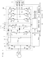
- Fig. 2 is a circuit diagram of an equivalent circuit of the direct power converter 100 illustrated in Fig. 1 .
- the equivalent circuit is introduced in, for example, Japanese Patent No. 5804167 and/or Japanese Patent No. 5874800 .
- the current irec1 is equivalently illustrated as the current irec1 that flows through a switch Srec when the switch Srec is in conduction.
- a current ic is equivalently illustrated as the current ic that flows through the switch Sc when the switch Sc is in conduction.
- a current that flows through the inductive load 6 through the inverter 5 when the output terminals Pu, Pv, and Pw of the inverter 5 are connected in common to the DC power source line LH or the DC power source line LL is also equivalently illustrated as a zero-phase current iz that flows through a switch Sz when the switch Sz is in conduction.
- the inverter 5 and the inductive load 6 are equivalently illustrated as a current source Idc that causes a DC current Idc to flow.
- Fig. 2 illustrates the reactor L4, the diode D40, and the switch Sl that constitute the charge circuit 4b.
- Fig. 2 illustrates the current il that flows through the reactor L4.
- Duties drec', dc', and dz' in which the switches Srec, Sc, and Sz are respectively in conduction are introduced in the equivalent circuit.
- 0 ⁇ drec' ⁇ 1, 0 ⁇ dc' ⁇ 1, 0 ⁇ dz' ⁇ 1, and drec' + dc' + dz' 1 hold.
- the duty drec' is a duty for setting a period in which the converter 3 can cause a current to flow to the DC link 7 to the inverter 5.
- the duty for setting the period in which the converter 3 can cause the current to flow to the DC link 7 to the inverter 5 may also be referred to as a "first duty".
- the duty dc' is a duty in which the capacitor C4 discharges.
- the duty in which the capacitor C4 discharges may also be referred to as a "second duty”.
- the duty dz' is a duty in which the zero-phase current iz flows through the inverter 5 independently from the voltage output by the inverter 5.
- the duty in which the zero-phase current iz flows through the inverter 5 independently from the voltage output by the inverter 5 may also be referred to as a "third duty".
- the DC current Idc is a current that flows to the inductive load 6 through the inverter 5.
- the currents irec1, ic, and iz are products of the DC current Idc and the duties drec', dc', and dz', respectively.
- the currents irec1, ic, and iz are average values in switching periods of the switches Srec, Sc, and Sz, respectively.
- the duties drec', dc', and dz' can be regarded as current distribution factors of the DC current Idc to the currents irec1, ic, and iz, respectively.
- the converter 3 When the converter 3 adopts a diode bridge, the converter 3 is unable to actively perform switching in accordance with the first duty drec'.
- the inverter 5 performs switching in accordance with the third duty dz' and the switch Sc performs switching in accordance with the second duty dc', and consequently the current irec1 can be obtained.
- Instantaneous power Pin input to the converter 3 is represented by Formula (1).
- an amplitude Im of the input current Iin is adopted and an input power factor is set to 1.
- the instantaneous power Pin has an AC component (-1/2) ⁇ Vm ⁇ Im ⁇ cos(2 ⁇ t) represented by the second term on the rightmost side of Formula (1).
- this AC component may also be referred to as an "AC component Pin ⁇ ”.
- Fig. 3 is a block diagram schematically illustrating power input and output in the direct power converter 100 illustrated in Fig. 1 .
- the power converter illustrated in Fig. 1 can be grasped as follows.
- the converter 3 rectifies the single-phase AC voltage Vin, converts AC power into DC power, and outputs the instantaneous power Pin.
- the power buffer circuit 4 buffers instantaneous power Pbuf between the converter 3 and the DC link 7.
- the instantaneous power Pbuf to be buffered is equal to a power difference (Pc - Pl) obtained by subtracting instantaneous power Pl from instantaneous power Pc.
- the instantaneous power Pl is input to the power buffer circuit 4 from the converter 3.
- the power buffer circuit 4 outputs the instantaneous power Pc to the DC link 7.
- the current iL is input to the charge circuit 4b from the converter 3, thus, the instantaneous power Pl is input.
- the instantaneous power Pc is instantaneous power obtained by the current ic that flows from the power buffer circuit 4 (more specifically, the discharge circuit 4a) to the DC link 7 and by the both-end voltage Vc.
- the instantaneous power Pdc is equal to instantaneous power Pout output by the inverter 5 if a loss in the inverter 5 is ignored.
- Instantaneous power Prec is instantaneous power obtained by the current irec1 that flows from the converter 3 to the DC link 7 through the filter 2 and the reverse current blocking circuit 8 and by the rectified voltage Vrec.
- the instantaneous power Prec is equal to a power difference (Pin - Pl).
- Pdc Prec + Pc holds.
- the inverter 5 converts DC voltage in the DC link 7 into AC voltage.
- the instantaneous power Pdc is input to the inverter 5 from the DC link 7.
- the inverter 5 outputs the load currents iu, iv, and iw.
- a DC voltage Vdc used in the DC link 7 to supply power to the inverter 5 is introduced.
- the DC voltage Vdc is noted as a voltage across the current source Idc in Fig. 2 .
- the DC current Idc can be represented by Formula (3).
- the DC voltage Vdc can be represented by Formula (4).
- Vdc Vrec ⁇ drec ′ + Vc ⁇ ⁇ dc ′ + 0 ⁇ dz ′
- the instantaneous power Pdc supplied to the inverter 5 from the DC power source lines LH and LL does not contain reactive power.
- the instantaneous power Pdc is represented by Formula (6) with the second term on the rightmost side of Formula (5) being ignored.
- control for implementing Formulas (3) and (4) can be performed by performing control for making ripples (AC components) in Formula (6) zero.
- Description of an example of a configuration for performing the aforementioned control is omitted, being publicly known in, for example, PTL 1.
- An original first duty drec and an original second duty dc are defined by Formulas (7) and (8), respectively.
- a command value Vdc* of the DC voltage Vdc can be adopted as the DC voltage Vdc. That is, the DC voltage Vdc is treated as a predetermined voltage below.
- Formulas (4) and (9) suggest the appropriateness of the control using the original first duty drec as the first duty drec' and the original second duty dc as the second duty dc'.
- the current irec1 in the case of performing the control using the original first duty drec is determined by using Formula (10).
- Fig. 4 depicts graphs illustrating an operation of the direct power converter 100 illustrated in Fig. 1 .
- the operation in the case where the current il takes the value il0 and control is performed in accordance with the original first duty drec and the original second duty dc is illustrated.
- dz 1 - dc - drec holds.
- the both-end voltage Vc precisely follows the command value Vc*.
- the uppermost portion illustrates the duties drec, dc, and dz.
- the second portion from the top illustrates the DC voltage Vdc, the voltages drec ⁇ Vrec and dc ⁇ Vc (see Formula (4)) constituting the DC voltage Vdc, and the DC current Idc.
- the third portion from the top illustrates the currents irec, ic, il, and irec1.
- the lowermost portion illustrates the instantaneous powers Pin, Pdc, Pbuf, Pc, -Pl, and Prec.
- a phase ⁇ t with a unit "degrees” is adopted and represented by the horizontal axis in Fig. 4 .
- Each of the instantaneous powers Pin, Pout, Pbuf, Pc, -Pl, and Prec is determined as a product of the voltage thus converted and the current.
- the input current Iin may distort from the sinusoidal wave.
- the value il0 represents the fundamental component of the current il.
- the original first duty drec is corrected in the following manner, and consequently the first duty drec' is obtained.
- the direct power converter 100 is controlled by using the first duty drec'.
- the first duty drec' with which a relationship represented by Formula (12) holds is introduced.
- Formula (10) is modified, and consequently Formula (13) is obtained.
- Formula (13) is further modified, and consequently Formula (14) is obtained.
- Formula (14) can be regarded as a value obtained by normalizing the DC current Idc by the effective value Im/ ⁇ 2 of the input current Iin.
- the correction amount ⁇ drec' is represented by Formula (15) by using Formula (14).
- the original first duty drec is represented as a first product.
- the first product is a product of a ratio (Vdc/Vm) of the DC voltage Vdc to the amplitude Vm and an absolute value
- the correction amount ⁇ drec' is a product of the ratio (Vdc/Vm), the value ⁇ 2, and a current (il0 - il)/(Im/ ⁇ 2).
- the current (il0 - il)/(Im/ ⁇ 2) can be regarded as a value obtained by normalizing the current (il0 - il) by the effective value Im/ ⁇ 2.
- the current (il0 - il) is a difference between the fundamental component il0 of the current il and the current il, and can be regarded as harmonic components of the current il.
- a product of the ratio (Vdc/Vm), the value ⁇ 2, and a value obtained by normalizing the harmonic components of the current il by the effective value Im/ ⁇ 2 is descried as a second product.
- the first duty drec' is the sum of the original first duty drec and the correction amount ⁇ drec', thus, is equal to the sum of the first product and the second product.
- the harmonic components of the current il are directly reflected in the current irec, and consequently influence the harmonic components of the input current Iin.
- the distortion of the input current Iin from the sinusoidal wave is reduced independently from the waveform of the current il.
- the original second duty dc is corrected in the following manner, and consequently the second duty dc' is obtained.
- the direct power converter 100 is controlled by using the second duty dc'.
- the second duty dc' with which a relationship represented by Formula (17) holds is introduced.
- the original second duty dc is represented as a third product. Since the both-end voltage Vc follows the command value Vc*, the both-end voltage Vc and the command value Vc* are considered to be equal to each other.
- the third product is a product of a ratio (Vdc/Vc) of the DC voltage Vdc to the both-end voltage Vc and a square cos 2 ( ⁇ t) of a cosine value cos( ⁇ t) of the phase ⁇ t.
- the correction amount ⁇ dc' is represented as a fourth product.
- the fourth product is a product of a ratio (Vm/Vc) of the amplitude Vm to the both-end voltage Vc, the second product that is equal to the correction amount ⁇ drec', and the absolute value (
- the second duty dc' is equal to a value obtained by subtracting the fourth product from the third product.
- the instantaneous power Pout is smoothed and ripples are removed independently from the waveform of the current il.
- the amplitude Im of the input current Iin and the DC current Idc are not required to obtain the original first duty drec, the original second duty dc, the correction amount ⁇ drec', and the correction amount ⁇ dc'.
- Partial switching is switching for simply controlling a charge current and is publicly known in " A Simple Switching Method for A Improved Power Factor Type Single Phase Converter (Suga, Kimata, and Uchida, IEEJ Transactions on Industry Applications, Vol. 116 No. 4, pp. 420-426, 1996 )” and in “ Single-Phase Twice Voltage PFC Converter for Air Conditioner” (Uesgi and four others, IEEJ Transactions on Industry Applications, Vol. 119 No. 5, p. 592-598, 1999 ).
- partial switching is adopted for switching of the switch Sl, so that the current il is controlled.
- the switch Sl is turned ON once and OFF once in a single period of the rectified voltage Vrec (this is equal to a half-period of the single-phase AC voltage Vin).
- the current il continuously flows in a period shorter than a half-period of the single-phase AC voltage Vin.
- the number of times of switching is less than that of a related-art active-buffer-based method.
- the number of times of switching reduces.
- the reduced number of times of switching is advantageous from the perspective of reducing the occurrence of noise caused by the switch Sl.
- An amount of the distortion of the input current Iin from the sinusoidal wave is desirably reduced from the perspective of reducing power source harmonics.
- an operation according to the present embodiment will be described by using, as an example, the current il obtained when partial switching is adopted.
- Fig. 5 is a graph illustrating a waveform of the current il obtained when partial switching is adopted.
- Fig. 5 illustrates a region for the phase ⁇ t of 0 to 180 degrees. Even in a region for the phase ⁇ t of 180 to 360 degrees, the current il has the same waveform.
- Fig. 5 also illustrates the waveform of the value il0. These waveforms are normalized by the effective value Im/ ⁇ 2.
- Detailed description of the settings of the phase at which the switch Sl is brought into conduction and the phase at which the switch Sl is brought out of conduction is omitted, being publicly known in PTL 1 and the aforementioned literatures "A Partial Switching Method for A Improved Power Factor Type Single Phase Converter” and "Single-Phase Twice Voltage PFC Converter for Air Conditioner".
- the waveform illustrated in Fig. 5 is adopted as the waveform of the current il.
- Fig. 6 also illustrates the various quantities as in Fig. 4 .
- the uppermost portion illustrates the duties drec', dc', and dz'.
- the second portion from the top illustrates the DC voltage Vdc, the voltages drec' ⁇ Vrec and dc' ⁇ Vc (see Formula (19)) constituting the DC voltage Vdc, and the DC current Idc.
- the third portion from the top illustrates the currents irec, ic, il, and irec1.
- the lowermost portion illustrates the instantaneous powers Pin, Pdc, Pbuf, Pc, -Pl, and Prec.
- Fig. 7 is a block diagram illustrating a configuration of the control device 10.
- the control device 10 includes an inverter control unit 101, a discharge control unit 102, and a charge control unit 103.
- the inverter control unit 101 outputs inverter control signals SSup, SSvp, SSwp, SSun, SSvn, and SSwn on the basis of the second duty dc', the first duty drec', and command values Vu*, Vv*, and Vw*.
- the command values Vu*, Vv*, and Vw* are command values of voltages Vu, Vv, and Vw output by the inverter 5, respectively.
- the inverter control signals SSup, SSvp, SSwp, SSun, SSvn, and SSwn control operations of the switching elements Sup, Svp, Swp, Sun, Svn, Swn, respectively.
- the inverter control unit 101 includes a voltage command generation unit 1011.
- the inverter control unit 101 further includes an amplitude modulation command unit 1012, a calculation unit 1013, a comparison unit 1014, and a logical calculation unit 1015.
- the amplitude modulation command unit 1012 controls the operation of the calculation unit 1013 on the basis of the second duty dc' and the first duty drec'.
- the calculation unit 1013 which is illustrated as symbols for only multipliers for the sake of simplicity of illustration, performs multiply-accumulate calculation by using the command values Vu*, Vv*, and Vw*, the second duty dc', and the first duty drec' to generate a signal wave M. Detailed description of the multiply-accumulate calculation is omitted, being a public known technique.
- the comparison unit 1014 compares the signal wave M with a value of a carrier CA, and outputs results of the comparison to the logical calculation unit 1015.
- the logical calculation unit 1015 performs logical calculation on the results and outputs the inverter control signals SSup, SSvp, SSwp, SSun, SSvn, and SSwn.
- the discharge control unit 102 includes a duty calculation unit 1021, a comparator 1022, and a duty correction unit 1023.
- the phase ⁇ , the amplitude Vm, the command value Vc* of the both-end voltage Vc, and the command value Vdc* of the DC voltage Vdc are input to the duty calculation unit 1021.
- the duty calculation unit 1021 determines the original first duty drec and the original second duty dc.
- the duty correction unit 1023 corrects the original first duty drec by using the correction amount ⁇ drec' to obtain the first duty drec'.
- the duty correction unit 1023 corrects the original second duty dc by using the correction amount ⁇ dc' to obtain the second duty dc'.
- the DC voltage Vdc which is required in the correction, is calculated from the original first duty drec, the original second duty dc, the amplitude Vm, the phase ⁇ , and the command value Vc* as indicated by Formula (9). Alternatively, the command value Vdc* may be used.
- the duty calculation unit 1021 and the duty correction unit 1023 can be collectively regarded as a duty generation unit 1020 that generates the second duty dc' and the first duty drec'.
- the comparator 1022 compares the second duty dc' with the carrier CA to generate a switch signal SSc.
- the switch signal SSc controls ON and OFF of the switch Sc.
- the charge control unit 103 includes a switch signal generation unit 1031.
- the switch signal generation unit 1031 generates a switch signal SSl.
- the switch signal SSl controls ON and OFF of the switch Sl. Details of the switch signal generation unit 1031 is omitted, being publicly known in the aforementioned literatures "A Simple Switching Method for A Improved Power Factor Type Single Phase Converter” and “Single-Phase Twice Voltage PFC Converter for Air Conditioner".
- the switch signal generation unit 1031 generates the switch signal SSl on the basis of the instantaneous power Pout and the amplitude Vm.
- the original first duty drec is corrected in the following manner, and consequently a first duty drec" is obtained.
- the direct power converter 100 is controlled by using the first duty drec".
- a correction amount il' is at least part of the harmonic components of the current il and has a dimension of the current.
- the correction amount il' is at least one frequency component among frequencies desired to be reduced in the input current Iin and is at least part of that component. That is, unlike ⁇ D.
- a desired quantity of a desired frequency component of the harmonic components of the current il is expected to be reduced.
- Formula (20) is obtained by systematically replacing the first duty drec' and the current (il0 - il) in Formula (12) with the first duty drec" and the correction amount il', respectively.
- Formula (21) is obtained in a manner similar to that of Formulas (15) and (16). Note that n ⁇ 2 unlike Formula (16) .
- the correction amount ⁇ drec" is a product of the ratio (Vdc/Vm), the value ⁇ 2, and a current (il')/(Im/ ⁇ 2).
- the current (il')/(Im/ ⁇ 2) can be regarded as a value obtained by normalizing the correction amount il' by the effective value Im/ ⁇ 2.
- the correction amount ⁇ drec" can also be regarded as the second product, and the first duty drec" is also equal to the sum of the first product and the second product.
- Formula (22) is obtained by systematically replacing the second duty dc' and the current (il0 - il) in Formula (17) with the second duty dc" and a value (-il'), respectively.
- the correction amount ⁇ dc" is also a product of the ratio (Vm/Vc) of the amplitude Vm to the both-end voltage Vc, the second product, and the absolute value (
- the correction amount ⁇ dc" can also be regarded as the fourth product.
- the second duty dc" is also equal to a value obtained by subtracting the fourth product from the third product like the second duty dc'.
- Formula (24) is obtained from Formulas (8) and (22).
- Formula (25) is obtained by performing substantially the same calculation as represented by Formula (19) by using the first duty drec" and the second duty dc" thus obtained. This indicates that control for making the DC voltage Vdc constant can be performed by adopting the first duty drec" and the second duty dc".
- the amplitude Im of the input current Iin and the DC current Idc are not required to obtain the original first duty drec, the original second duty dc, the correction amount ⁇ drec", and the correction amount ⁇ dc".
- the correction amounts ⁇ drec" and ⁇ dc" are based on the correction amount il', the desired quantity of the desired frequency component of the harmonic components of the current il can be reduced.
- Fig. 8 is a graph illustrating the waveform of the current il.
- Fig. 8 illustrates a region of a half-period of the single-phase AC voltage Vin, specifically, a region of the phase ⁇ t of 0 to 180 degrees. Even in a region for the phase ⁇ t of 180 to 360 degrees, the current il has the same waveform. The current il normalized by the effective value Im/ ⁇ 2 is illustrated.
- the phase at which the switch Sl transitions from non-conduction to conduction is about 36 degrees.
- the phase at which the switch Sl transitions from conduction to non-conduction is about 68 degrees.
- the current il takes the largest value.
- the current il decreases thereafter as the phase increases.
- the current il becomes equal to 0 at about 155 degrees.
- Fig. 9 depicts graphs illustrating an operation of the direct power converter 100 in the case where the first duty drec", the second duty dc", and "third duty dz" are set when such a correction amount il' is adopted.
- dz" 1 - drec" - dc” holds.
- Fig. 9 also illustrates the various quantities as in Fig. 6 .
- the uppermost portion illustrates the duties drec", dc", and dz".
- the second portion from the top illustrates the DC voltage Vdc, the voltages drec" ⁇ Vrec and dc" ⁇ Vc constituting the DC voltage Vdc, and the DC current Idc.
- the third portion from the top illustrates the currents irec, ic, il, and irec1.
- the lowermost portion illustrates the instantaneous powers Pin, Pdc, Pbuf, Pc, -Pl, and Prec.
- Vdc 0.82Vm
- the smallest value of the third duty dz" can be made equal to 0 instead of a positive value.
- the distortion of the waveform of the current il illustrated in Fig. 7 is greater than that of the current il illustrated in Fig. 5 .
- Control is performed based only on a desired amount (value equivalent to the current of 0.571 A) of a harmonic component (3rd harmonic component in this case) of a particular frequency in the operation illustrated in Fig. 9 , whereas control for reducing all the harmonic components is performed in the operation illustrated in Fig. 6 .
- Fig. 10 is a block diagram illustrating a first configuration of the discharge control unit 102 for obtaining the first duty drec" and the second duty dc" and components therearound.
- Such a discharge control unit 102 also constitutes the control device 10 along with the inverter control unit 101 and the charge control unit 103 illustrated in Fig. 7 .
- the discharge control unit 102 includes a correction amount generation unit 1025 in addition to the duty calculation unit 1021, the comparator 1022, and the duty correction unit 1023 described using Fig. 7 .
- the correction amount il' is input to the duty correction unit 1023 in place of the current il.
- the duty correction unit 1023 corrects the original first duty drec by using the correction amount ⁇ drec" to obtain the first duty drec".
- the duty correction unit 1023 corrects the original second duty dc by using the correction amount ⁇ dc" to obtain the second duty dc".
- the correction amount generation unit 1025 generates the correction amount il' to be reduced on the basis of the relationship between the input current Iin and the permissible amount of the harmonic component, and outputs the correction amount il'. For example, a table that determines the permissible value for the magnitude of the input current Iin is stored in the correction amount generation unit 1025.
- the correction amount generation unit 1025 is capable of calculating the input current Iin on the basis of the instantaneous power Pout, the amplitude Vm, and the phase ⁇ t.
- Formula (26) can be adopted.
- the correction amount il' is determined on the basis of the distortion of the input current Iin.
- the control device 10 does not require the current il.
- Fig. 11 is a block diagram illustrating a second configuration of the discharge control unit 102 for obtaining the first duty drec" and the second duty dc" and components therearound.
- Such a discharge control unit 102 also constitutes the control device 10 along with the inverter control unit 101 and the charge control unit 103 illustrated in Fig. 7 .
- the discharge control unit 102 includes a correction amount generation unit 1026 in addition to the duty calculation unit 1021, the comparator 1022, and the duty correction unit 1023 described using Fig. 7 .
- the correction amount il' is input to the duty correction unit 1023 in place of the current il.
- the duty correction unit 1023 corrects the original first duty drec by using the correction amount ⁇ drec" to obtain the first duty drec".
- the duty correction unit 1023 corrects the original second duty dc by using the correction amount ⁇ dc" to obtain the second duty dc".
- the correction amount generation unit 1026 performs fast Fourier transform on the current il to determine an amplitude Ilh(n) for each of the n-th frequency components thereof.
- the order of a harmonic exceeding a permissible value set for the corresponding order is selected.
- an amount by which the amplitude Ilh( ⁇ ) of the ⁇ -th harmonic component exceeds the permissible value set for the ⁇ -th harmonic is determined as the correction amount Il'( ⁇ ) for the ⁇ -th harmonic.
- the correction amount Il'( ⁇ ) ( ⁇ ⁇ ⁇ ) for the order not selected is set to 0.
- Inverse fast Fourier transform is performed using the correction amount Il'(n) or the correction amount Il'( ⁇ ), and consequently the correction amount il' is determined.
- the correction amount il' is determined on the basis of the distortion of the current il.
- the original first duty drec is represented as the first product.
- the first product is the product of the ratio (Vdc/Vm) of the DC voltage Vdc to the amplitude Vm and the absolute value
- the correction amounts ⁇ drec' and ⁇ drec" are each represented as the second product.
- the second product is a product of the ratio (Vdc/Vm), the value ⁇ 2, and the predetermined current.
- the first duty drec' is the sum of the original first duty drec and the correction amount ⁇ drec'.
- the first duty drec" is the sum of the original first duty drec and the correction amount ⁇ drec".
- each of the first duties drec' and drec" is equal to the sum of the first product and the second product.
- the predetermined current is a current obtained by normalizing at least part of a harmonic component of the current il or the difference (il0 - il) between the fundamental component il0 of the current il and the current il by the effective value (Im/ ⁇ 2) of the input current Iin.
- the correction amount ⁇ drec is equal to the second product.
- the predetermined current is the current obtained by normalizing the difference (il0 - il) between the fundamental component il0 of the current il and the current il by the effective value (Im/ ⁇ 2)
- the correction amount ⁇ drec' is equal to the second product.
- the second product generally represents each of the correction amounts ⁇ drec' and ⁇ drec".
- each of the second duties dc' and dc" is equal to a value obtained by subtracting the fourth product from the third product.
- the third product is the product of the ratio (Vdc/Vc) of the DC voltage Vdc to the both-end voltage Vc (or the command value Vc* thereof) and the square cos 2 ( ⁇ t) of the cosine value cos( ⁇ t) of the phase ⁇ t.
- the fourth product is the product of the ratio (Vm/Vc) of the amplitude Vm to the both-end voltage Vc, the second product, and the absolute value
- the second product generally represents each of the correction amounts ⁇ drec' and ⁇ drec".
- the fourth product is equal to the correction amount ⁇ dc' and the third product and the fourth product are equal to the second duty dc'.
- the fourth product is equal to the correction amount ⁇ dc" and the third product and the fourth product are equal to the second duty dc".
- Adopting the second duty dc' or dc" in place of the original second duty dc is advantageous from the perspective of reducing ripples in the instantaneous power Pout output by the inverter 5.
- the current (il0 - il) can be determined by a content of the harmonic components included in the input current Iin with respect to the fundamental wave of the input current.
- the correction amount il' is a content of at least part of at least one frequency component of the harmonic components included in the current il with respect to the fundamental wave of the input current Iin.
- the original first duty drec can be determined by using the first product.
- the correction amount ⁇ drec' or ⁇ drec" can be determined by using the second product.
- the original second duty dc can be determined by using the third product.
- the correction amount ⁇ dc' or ⁇ dc" can be determined by using the fourth product.
- the first product and the third product are obtained by the duty calculation unit 1021, and the second product and the fourth product are obtained by the duty correction unit 1023.
- the switch Sl can be turned ON once and OFF once in a single period of the rectified voltage Vrec (this is also a half-period of the AC voltage Vin), so that the switch Sl can be caused to perform partial switching. Partial switching involves a less number of times of switching and thus is advantageous from the perspective of reducing switching noise.
- the switch signal SSl for turning ON and OFF the switch Sl is generated by the switch signal generation unit 1031.
- Fig. 12 is a graph illustrating spectra of the harmonics of the input current Iin when the current il illustrated in Fig. 13 flows.
- the horizontal axis represents the orders (except for the 1st harmonic which corresponds to the fundamental component), and the harmonic components are represented by bars.
- IEC 61000-3-12 is known in addition to IEC 61000-3-2 mentioned above.
- Fig. 12 illustrates spectra in view of IEC 61000-3-12.
- Fig. 13 is a graph illustrating the waveform of the current il with which the spectra illustrated in Fig. 12 are obtained.
- Fig. 13 illustrates a region for the phase ⁇ t of 0 to 180 degrees. Even in a region for the phase ⁇ t of 180 to 360 degrees, the current il has the same waveform.
- Fig. 13 also illustrates the waveform of the value il0. These waveforms are normalized by the effective value Im/ ⁇ 2.
- IEC 61000-3-12 defines permissible values (upper limits) for harmonic components up to the 13-th harmonic component.
- the permissible values are represented by a zigzag line G2 in Fig. 12 .
- the vertical axis represents a content of the harmonic current with respect to the fundamental component.
- the permissible values, converted into the contents with respect to the fundamental component of the input current Iin are illustrated. This conversion is conversion based on IEC 61000-3-12 Edition 2.0 (2004) instead Edition 1.0 (2011).
- IEC 61000-3-12 Edition 1.0 defines permissible values (upper limits) for the total harmonic distortion (denoted by TH in Fig. 12 ) and the partial weighted harmonic distortion (denoted by PW in Fig. 12 ) of the current. In Fig. 12 , these permissible values are illustrated by a straight line G3. Since the permissible value for the total harmonic distortion and the permissible value for the partial weighted harmonic distortion are equal to each other, the straight line G3 is not a zigzag line.
- the value represented by the zigzag line G2 and the value represented by the straight line G3 are permissible values in the case where a short circuit ratio is equal to 33.
- the 3rd harmonic and the total harmonic distortion exceed the permissible values defined by IEC 61000-3-12.
- the partial weighted harmonic distortion is below the permissible value defined by IEC 61000-3-12.
- the partial weighted harmonic distortion is calculated based on the 14-th to 40-th harmonic components. Thus, discussion is given by excluding the 14-th to 40-th harmonic components from the orders of the harmonic components to be reduced in the current il.
- An approximate waveform ilm is determined by calculation reconstructed using the fundamental component and the 2nd to 13th harmonic components of the current il from the perspective of this order exclusion.
- Fig. 13 also illustrates the approximate waveform ilm.
- the 3rd harmonic component of the input current Iin is 106.3% of the permissible value defined by IEC 61000-3-12 for the 3rd harmonic component.
- the 3rd harmonic component of the current il is reduced by a reduction value greater than or equal to a current equivalent to 6.3% of the permissible value.
- the total harmonic distortion is based on the 2nd to 40th harmonic components.
- the 3rd harmonic component of the current il can be reduced such that the total harmonic distortion of the input current Iin satisfies the permissible value defined by IEC 61000-3-12 as a result of the reduction of the 3rd harmonic component of the current il.
- Fig. 14 is a graph illustrating spectra of harmonics of the input current Iin.
- Fig. 14 illustrates bars in the case where the 3rd harmonic component of the current il illustrated in Fig. 13 is reduced by the current value equivalent to 7.2% of the permissible value defined by IEC 61000-3-12 in addition to bars illustrated in Fig. 12 .
- Two bars for the same order are illustrated side by side. The bar on the left side represents the case illustrated in Fig. 12 , and the bar on the right side represents the case where the 3rd harmonic component is reduced.
- the 3rd harmonic component of the input current Iin represented by the bar on the right side is lower than the permissible value defined by IEC 61000-3-12.
- the total harmonic distortion of the input current Iin represented by the bar on the right side satisfies the permissible value defined by IEC 61000-3-12.
- FIG. 15 is a graph illustrating spectra of the harmonics of the input current Iin when the current il illustrated in Fig. 13 flows.
- the horizontal axis represents the orders (except for the 1st harmonic which corresponds to the fundamental component), and the harmonic components are represented by bars.
- Fig. 15 illustrates spectra in view of IEC 61000-3-2.
- IEC 61000-3-2 defines permissible values (upper limits) of harmonic components up to the 40-th harmonic component.
- the permissible values are represented by a zigzag line G1 in Fig. 15 .
- the vertical axis denotes the harmonic current.
- the 3rd and 7th harmonic components of the input current Iin exceed the permissible values defined by IEC 61000-3-2. Thus, these are desirably reduced. Note that since the vertical axis represents the harmonic current, the permissible values converted into the current values in consideration of the fundamental component of the input current Iin are illustrated.
- Fig. 16 depicts graphs illustrating an operation of the direct power converter 100.
- Fig. 16 illustrates the case where the first duty drec", the second duty dc", and the third duty dz" are set with which the 3rd and 7th harmonic components of the current il are reduced such that the 3rd and 7th harmonic components of the input current Iin satisfy the permissible values defined by IEC 61000-3-2.
- Fig. 16 also illustrates the various quantities as in Figs. 6 and 9 .
- the uppermost portion illustrates the duties drec", dc", and dz".
- the second portion from the top illustrates the DC voltage Vdc, the voltages drec" ⁇ Vrec and dc" ⁇ Vc constituting the DC voltage Vdc, and the DC current Idc.
- the third portion from the top illustrates the currents irec, ic, il, and irec1.
- the lowermost portion illustrates the instantaneous powers Pin, Pdc, Pbuf, Pc, -Pl, and Prec.
- Vdc 0.81Vm
- the smallest value of the third duty dz" can be made equal to 0 instead of a positive value.
- the distortion of the waveform of the input current Iin from the sinusoidal wave is reduced.
- Adopting the second duty dc' or dc" in place of the original second duty dc is advantageous from the perspective of reducing ripples in the instantaneous power Pout output by the inverter 5.
- the correction amounts ⁇ drec" and ⁇ dc" are based on the correction amount il', the desired quantity of the desired frequency component of the harmonic components of the current il can be reduced.
- the amplitude Im of the input current Iin and the DC current Idc are not required to obtain the original first duty drec and the original second duty dc as indicated by Formulas (7) and (8).
- the correction amounts ⁇ drec', ⁇ dc', ⁇ drec", and ⁇ dc" are obtained without using the amplitude Im and the DC current Idc as indicated by Formulas (16), (18), (21), and (23) .
- Performing partial switching by turning the switch Sl ON once and OFF once in a half-period of the AC voltage Vin is advantages from the perspective of reducing switching noise by a reduced number of times of switching.
Abstract
Description
- The present disclosure relates to a technique for converting power.
- A component that ripples at a frequency twice a power source frequency is present in power obtained from a single-phase AC power source. To obtain a constant DC voltage by using a rectification circuit, a large-capacitance energy accumulation element is desired.
- There has been proposed a technique for connecting a capacitor that constitutes an active buffer to a DC link through a switching element and causing the capacitor to function as a voltage source. In such a technique, the waveform of a current that flows through the active buffer is basically a sinusoidal wave.
-
PTL 1 is cited as a related-art literature relating to the present disclosure. - PTL 1:
Japanese Patent No. 6265297 - The present disclosure provides a technique for reducing a distortion, from a sinusoidal wave, of a waveform of an input current input to a power converter.
- A control device for a direct power converter according to the present disclosure is a control device (10) that controls a direct power converter (100). The direct power converter includes a DC link (7); a converter (3) that rectifies a single-phase AC voltage (Vin), converts AC power into DC power, and outputs first instantaneous power (Pin); a power buffer circuit (4) that receives and supplies power between the converter and the DC link and buffers second instantaneous power (Pbuf); and an inverter (5) that converts a DC voltage in the DC link into an AC voltage and outputs the AC voltage.
- The control device according to a first aspect includes a duty generation unit (1020) that generates a first duty (drec', drec") and a second duty (dc', dc"), the first duty being a duty in which a first current (irec1) flows from the converter to the DC link, the second duty being a duty in which a second current (ic) flows from the power buffer circuit to the DC link; and an inverter control unit (101) that outputs an inverter control signal (SSup, SSvp, SSwp, SSun, SSvn, SSwn) for controlling an operation of the inverter, on the basis of the first duty, the second duty, and a command value (Vu*, Vv*, Vw*) of a voltage output by the inverter.
- The first duty is equal to a sum of a first product and a second product. The first product is a product of a first ratio (Vdc/Vm) of a predetermined voltage (Vdc) to an amplitude (Vm) of the single-phase AC voltage and an absolute value (|sin(ωt)|) of a sine value of a phase (ωt) of the single-phase AC voltage. The second product is a product (√2·(il0 - il)·(Vdc/Vm), √2·il'·(Vdc/Vm)) of a third current (il0 - il, il'), the first ratio, and a value √2.
- The third current is a current obtained by normalizing at least part of a harmonic component (il') of a fourth current (il) input to the power buffer circuit from the DC link or a difference (il0 - il) between a fundamental component of the fourth current and the fourth current by an effective value (Im/√2) of an input current (Iin) input to the converter (3).
- In the direct power converter controlled by the control device according to a second aspect, the power buffer circuit (4) includes a discharge circuit (4a) including a capacitor (C4) and a first switch (Sc, D42) that connects the capacitor to the DC link; and a charge circuit (4b) that charges the capacitor.
- The control device according to the second aspect is the control device according to the first aspect that outputs a first switch signal (SSc) for bringing the first switch into conduction, on the basis of the second duty (dc', dc").
- The second duty is equal to a value obtained by subtracting a fourth product from a third product. The third product is a product of a second ratio (Vdc/Vc) of the predetermined voltage (Vdc) to a both-end voltage (Vc, Vc*) and a square (cos2(ωt)) of a cosine value of the phase (ωt) of the single-phase AC voltage, the both-end voltage being a voltage across the capacitor. The fourth product is a product of a third ratio (Vm/Vc) of the amplitude (Vm) to the both-end voltage, the second product (√2·(il0 - il)·(Vdc/Vm), √2·il'·(Vdc/Vm)), and the absolute value (|sin(ωt)|) of the sine value.
- The control device according to a third aspect is the control device according the second aspect, in which the third current (il0 - il) is determined from a content of harmonic components included in the input current (Iin) with respect to a fundamental of the input current.
- The control device according to a fourth aspect is the control device according to the second aspect, in which the third current (il') is a content of at least part of at least one frequency component of harmonic components included in the fourth current (il) with respect to a fundamental of the input current (Iin).
- The control device according to a fifth aspect is the control device according to any one of the second aspect to the fourth aspect, in which the duty generation unit includes a duty calculation unit (1021) that obtains an original first duty (drec) by using the first product and obtains an original second duty (dc) by using the third product; and a duty correction unit (1023) that obtains the first duty (drec', drec") from the second product and the original first duty and obtains the second duty (dc', dc") from the fourth product and the original second duty.
- In the direct power converter controlled by the control device according to a sixth aspect, the charge circuit (4b) includes a reactor (L4) that accumulates energy in the capacitor (C4); and a second switch (Sl, D41) that connects the converter (3) to the reactor and causes the reactor to accumulate energy.
- The control device according to the sixth aspect is the control device according to any one of the second aspect to the fifth aspect that further includes a switch signal generation unit (1031) that generates a second switch signal (SSl) for turning the second switch ON once and OFF once in a half-period of the single-phase AC voltage (Vin).
- The control device for a direct power converter according to the first aspect of this disclosure reduces a distortion of a waveform of the input current with respect to a sinusoidal wave.
- The control device for a direct power converter according to the second to fifth aspects of this disclosure is advantageous from the perspective of reducing ripples in power output by the inverter.
- The control device for a direct power converter according to the sixth aspect of this disclosure is advantageous from the perspective of reducing switching noise.
-
- [
Fig. 1] Fig. 1 is a block diagram illustrating a configuration of a direct power converter. - [
Fig. 2] Fig. 2 is a circuit diagram of an equivalent circuit of the direct power converter. - [
Fig. 3] Fig. 3 is a block diagram schematically illustrating power input and output in the direct power converter. - [
Fig. 4] Fig. 4 depicts graphs illustrating an operation of the direct power converter. - [
Fig. 5] Fig. 5 is a graph illustrating waveforms of currents that flow through a reactor. - [
Fig. 6] Fig. 6 depicts graphs illustrating an operation of the direct power converter. - [
Fig. 7] Fig. 7 is a block diagram illustrating a configuration of a control device. - [
Fig. 8] Fig. 8 is a graph illustrating a waveform of a current that flows through the reactor. - [
Fig. 9] Fig. 9 depicts graphs illustrating an operation of the direct power converter. - [
Fig. 10] Fig. 10 is a block diagram illustrating a first configuration of a discharge control unit and components therearound. - [
Fig. 11] Fig. 11 is a block diagram illustrating a second configuration of the discharge control unit and the components therearound. - [
Fig. 12] Fig. 12 is a graph illustrating spectra of harmonics of an input current. - [
Fig. 13] Fig. 13 is a graph illustrating waveforms of currents that flow through the reactor. - [
Fig. 14] Fig. 14 is a graph illustrating spectra of harmonics of the input current. - [
Fig. 15] Fig. 15 is a graph illustrating spectra of harmonics of the input current. - [
Fig. 16] Fig. 16 depicts graphs illustrating an operation of the direct power converter. -
Fig. 1 is a block diagram illustrating a configuration of adirect power converter 100. A control technique according to the present disclosure is applicable to thedirect power converter 100. Thedirect power converter 100 includes aconverter 3, afilter 2, apower buffer circuit 4, aninverter 5, and aDC link 7. Thepower buffer circuit 4 functions as the aforementioned active buffer. - The
converter 3 adopts, for example, a diode bridge and includes diodes D31 to D34. The diodes D31 to D34 constitute a bridge circuit. A single-phase AC voltage Vin (= Vm·sin(ωt)) is input to theconverter 3 from a single-phaseAC power source 1. Theconverter 3 performs single-phase full-wave rectification on the AC voltage Vin to obtain a rectified voltage Vrec (= |Vin|) and outputs the rectified voltage Vrec to thefilter 2 and thepower buffer circuit 4. An input current Iin flows into theconverter 3 from the single-phaseAC power source 1. Theconverter 3 outputs a current irec (= |Iin|; Iin = Im·sin(ωt)). - The
filter 2 includes a reactor L2 and a capacitor C2. One end of the reactor L2 is connected to a high-potential terminal 3A on an output side of theconverter 3, specifically, to both of a cathode of the diode D31 and a cathode of the diode D33. Another end of the reactor L2 is connected, through the capacitor C2, to a low-potential terminal 3B on an output side of theconverter 3, specifically, to both of an anode of the diode D32 and an anode of the diode D34. - Thus, in the
filter 2, the rectified voltage Vrec is input to series connection of the reactor L2 and the capacitor C2, and a voltage retained by the capacitor C2 is output. Note that thefilter 2 functions to remove a highfrequency component of the current. Thus, the voltage retained by the capacitor C2 is also treated to be equal to the rectified voltage Vrec in the description below. - The
DC link 7 includes a DC power source line LL and a DC power source line LH having a higher potential than the DC power source line LL. The DC power source line LH is connected to the high-potential terminal 3A of theconverter 3 through a reverse current blocking circuit 8 (described later) and the reactor L2. The DC power source line LL is connected to the low-potential terminal 3B of theconverter 3. - The
power buffer circuit 4 includes adischarge circuit 4a and acharge circuit 4b. Thepower buffer circuit 4 receives and supplies power between theconverter 3 and theDC link 7. Thedischarge circuit 4a includes a capacitor C4 serving as a buffer capacitor. Thecharge circuit 4b boosts the rectified voltage Vrec and charges the capacitor C4. - The
discharge circuit 4a further includes a diode D42 and a transistor (insulated gate bipolar transistor in this case: hereinafter abbreviated as "IGBT") Sc connected in antiparallel with the diode D42. The transistor Sc is connected in series with the capacitor C4 between the DC power source line LH and the DC power source line LL to be closer to the DC power source line LH than the capacitor C4 is. - The antiparallel connection mentioned herein indicates parallel connection with forward directions opposite to each other. Specifically, the forward direction of the transistor Sc is a direction from the DC power source line LL to the DC power source line LH, and the forward direction of the diode D42 is a direction from the DC power source line LH to the DC power source line LL. The transistor Sc and the diode D42 can be collectively regarded as a single switch element (switch Sc). When the switch Sc is conducting, the capacitor C4 is connected to the
DC link 7 and the capacitor C4 discharges and provides power to theDC link 7. - The
charge circuit 4b includes, for example, a diode D40, a reactor L4, and a transistor (IGBT in this case) Sl. The diode D40 has a cathode and an anode. The cathode is connected between the switch Sc and the capacitor C4. Such a configuration is known as a so-called boost chopper. - The reactor L4 is connected between the high-
potential terminal 3A and the anode of the diode D40. The transistor Sl is connected between the DC power source line LL and the anode of the diode D40. The transistor Sl and a diode D41 are connected in antiparallel with each other, and can be collectively regarded as a single switch element (switch Sl). Specifically, the forward direction of the transistor Sl is a direction from the high-potential terminal 3A to the low-potential terminal 3B, and the forward direction of the diode D41 is a direction from the low-potential terminal 3B to the high-potential terminal 3A. - The capacitor C4 is charged by the
charge circuit 4b. A voltage Vc across the capacitor C4 (hereinafter, simply referred to as "both-end voltage") is higher than the rectified voltage Vrec. The switch Sl conducts to connect theconverter 3 to the reactor L4 and to accumulate energy in the reactor L4. Specifically, a current is caused to flow from the high-potential terminal 3A to the low-potential terminal 3B through the switch Sl, and consequently energy is accumulated in the reactor L4. Then, the switch Sl is turned OFF, and consequently the energy is accumulated in the capacitor C4 through the diode D40. - Since the both-end voltage Vc is higher than the rectified voltage Vrec, a current does not flow through the diode D42 as a rule. Thus, whether the switch Sc is conducting or not depends solely on whether the transistor Sc is conducting or not. Here, the diode D42 ensures a reverse breakdown voltage when the both-end voltage Vc is lower than the rectified voltage Vrec, and brings a current flowing back from an
inductive load 6 to theDC link 7 into reverse conduction when theinverter 5 abnormally stops. - Since the forward direction of the diode D41 is a direction from the low-
potential terminal 3B to the high-potential terminal 3A, a current does not flow through the diode D41 as a rule. Thus, whether the switch Sl is conducting or not depends solely only on whether the transistor Sl is conducting or not. The diode D41 is a diode that provides a reverse breakdown voltage and reverse conduction. Although the diode D41 is illustrated as a diode included in the transistor Sl implemented by an IGBT, the diode D41 itself does not involve in operation of the circuit. - The reverse
current blocking circuit 8 is provided between thefilter 2 and the DC power source line LH and blocks a current that flows back from thedischarge circuit 4a to thefilter 2. The reversecurrent blocking circuit 8 is implemented by, for example, a diode D43. An anode of the diode D43 is connected to thefilter 2, more specifically, to the high-potential terminal 3A through the reactor L2. A cathode of the diode D43 is connected to the DC power source line LH. Such a reversecurrent blocking circuit 8 is publicly known due to, for example,Japanese Patent No. 5772915 - A current irec1 that is input to the reverse
current blocking circuit 8 from theconverter 3 through thefilter 2 and a current il that flows from theconverter 3 to thepower buffer circuit 4, specifically, to thecharge circuit 4b, without through thefilter 2 are introduced. Then, a current irec output from theconverter 3 is a sum of the current irec1 and the current il. The current il flows through the reactor L4 and is in a relationship of il = irec - irec1. The current il is measured by a well-known current sensor, for example. Illustration of the configuration for obtaining the current il is omitted, being a well-known technique. - Since the both-end voltage Vc is higher than the rectified voltage Vrec, the current irec1 takes a value of 0 when the switch Sc is in conduction.
- Note that instead of being connected directly to the high-
potential terminal 3A, the reactor L4 may be connected through the reactor L2. In such a case, however, the current il also flows through thefilter 2 instead of the current irec1. Thus, a large current-carrying capacity is desired for thefilter 2. In other words, from the perspective of reducing the current-carrying capacity of thefilter 2 and consequently reducing the size of thefilter 2, the reactor L4 is desirably connected to a position closer to theconverter 3 than thefilter 2 is. - The
inverter 5 converts a DC voltage in theDC link 7, more specifically, across the DC power source line LH and the DC power source line LL, into an AC voltage and outputs the AC voltage to output terminals Pu, Pv, and Pw. The DC voltage is the both-end voltage Vc when the switch Sc is in conduction. The DC voltage is the rectified voltage Vrec when the switch Sc is not in conduction if a voltage drop at the reversecurrent blocking circuit 8 and the reactor L2 is ignored. - The
inverter 5 is, for example, a three-phase voltage inverter and includes six switching elements Sup, Svp, Swp, Sun, Svn, and Swn. The switching element Sup is connected between the output terminal Pu and the DC power source line LH. The switching element Svp is connected between the output terminal Pv and the DC power source line LH. The switching element Swp is connected between the output terminal Pw and the DC power source line LH. The switching element Sun is connected between the output terminal Pu and the DC power source line LL. The switching element Svn is connected between the output terminal Pv and the DC power source line LL. The switching element Swn is connected between the output terminal Pw and the DC power source line LL. Theinverter 5 constitutes a so-called voltage inverter and includes six diodes Dup, Dvp, Dwp, Dun, Dvn, and Dwn. - Each of the diodes Dup, Dvp, Dwp, Dun, Dvn, and Dwn is arranged such that a cathode thereof is directed toward the DC power source line LH and an anode thereof is directed toward the DC power source line LL. The diode Dup is connected in parallel with the switching element Sup between the output terminal Pu and the DC power source line LH. Likewise, the diode Dvp is connected in parallel with the switching element Svp, the diode Dwp is connected in parallel with the switching element Swp, the diode Dun is connected in parallel with the switching element Sun, the diode Dvn is connected in parallel with the switching element Svn, and the diode Dwn is connected in parallel with the switching element Swn. A load current iu is output from the output terminal Pu. A load current iv is output from the output terminal Pv. A load current iw is output from the output terminal Pw. The load currents iu, iv, and iw form a three-phase AC current. For example, IGBTs are adopted as all the switching elements Sup, Svp, Swp, Sun, Svn, and Swn.
- The
inductive load 6 is, for example, a rotary machine, and is illustrated by an equivalent circuit representing an inductive load. Specifically, a reactor Lu and a resistor Ru are connected in series to each other, and one terminal of this series body is connected to the output terminal Pu. The same applies to reactors Lv and Lw and resistors Rv and Rw. Other ends of these series bodies are connected to each other. - The
inductive load 6 serving as a synchronous machine will be described. Avelocity detector 9 detects the load currents iu, iv, and iw that flow through theinductive load 6. Thevelocity detector 9 provides acontrol device 10 for a direct power converter, with a rotation angular velocity ωm of thesynchronous machine 6, a q-axis current Iq, and a d-axis current Id (strictly speaking, information indicating these; the same applies to below) that are obtained from the load currents iu, iv, and iw. - The amplitude Vm of the single-phase AC voltage Vin, the angular velocity ω (or a phase θ = ωt which is a product of the angular velocity ω and time t), a command value ωm* of the rotation angular velocity ωm, and the current il are input to the
control device 10 in addition to the rotation angular velocity ωm, the q-axis current Iq, and the d-axis current Id. -
Fig. 2 is a circuit diagram of an equivalent circuit of thedirect power converter 100 illustrated inFig. 1 . The equivalent circuit is introduced in, for example,Japanese Patent No. 5804167 Japanese Patent No. 5874800 - A current that flows through the
inductive load 6 through theinverter 5 when the output terminals Pu, Pv, and Pw of theinverter 5 are connected in common to the DC power source line LH or the DC power source line LL is also equivalently illustrated as a zero-phase current iz that flows through a switch Sz when the switch Sz is in conduction. - The
inverter 5 and theinductive load 6 are equivalently illustrated as a current source Idc that causes a DC current Idc to flow. -
Fig. 2 illustrates the reactor L4, the diode D40, and the switch Sl that constitute thecharge circuit 4b.Fig. 2 illustrates the current il that flows through the reactor L4. - Duties drec', dc', and dz' in which the switches Srec, Sc, and Sz are respectively in conduction are introduced in the equivalent circuit. As is publicly known from
Japanese Patent No. 5804167 Japanese Patent No. 5874800 - The duty drec' is a duty for setting a period in which the
converter 3 can cause a current to flow to theDC link 7 to theinverter 5. Hereinafter, the duty for setting the period in which theconverter 3 can cause the current to flow to theDC link 7 to theinverter 5 may also be referred to as a "first duty". - The duty dc' is a duty in which the capacitor C4 discharges. Hereinafter, the duty in which the capacitor C4 discharges may also be referred to as a "second duty".
- The duty dz' is a duty in which the zero-phase current iz flows through the
inverter 5 independently from the voltage output by theinverter 5. Hereinafter, the duty in which the zero-phase current iz flows through theinverter 5 independently from the voltage output by theinverter 5 may also be referred to as a "third duty". - The DC current Idc is a current that flows to the
inductive load 6 through theinverter 5. The currents irec1, ic, and iz are products of the DC current Idc and the duties drec', dc', and dz', respectively. The currents irec1, ic, and iz are average values in switching periods of the switches Srec, Sc, and Sz, respectively. The duties drec', dc', and dz' can be regarded as current distribution factors of the DC current Idc to the currents irec1, ic, and iz, respectively. - When the
converter 3 adopts a diode bridge, theconverter 3 is unable to actively perform switching in accordance with the first duty drec'. Theinverter 5 performs switching in accordance with the third duty dz' and the switch Sc performs switching in accordance with the second duty dc', and consequently the current irec1 can be obtained. - Overview of Operation of
Power Buffer Circuit 4. - Instantaneous power Pin input to the
converter 3 is represented by Formula (1). In derivation of Formula (1), an amplitude Im of the input current Iin is adopted and an input power factor is set to 1. - [Math. 1]

- The instantaneous power Pin has an AC component (-1/2)·Vm·Im·cos(2ωt) represented by the second term on the rightmost side of Formula (1). Hereinafter, this AC component may also be referred to as an "AC component Pin^".
-
Fig. 3 is a block diagram schematically illustrating power input and output in thedirect power converter 100 illustrated inFig. 1 . - The power converter illustrated in
Fig. 1 can be grasped as follows. - The
converter 3 rectifies the single-phase AC voltage Vin, converts AC power into DC power, and outputs the instantaneous power Pin. Thepower buffer circuit 4 buffers instantaneous power Pbuf between theconverter 3 and theDC link 7. The instantaneous power Pbuf to be buffered is equal to a power difference (Pc - Pl) obtained by subtracting instantaneous power Pl from instantaneous power Pc. The instantaneous power Pl is input to thepower buffer circuit 4 from theconverter 3. Thepower buffer circuit 4 outputs the instantaneous power Pc to theDC link 7. - The current iL is input to the
charge circuit 4b from theconverter 3, thus, the instantaneous power Pl is input. The instantaneous power Pc is instantaneous power obtained by the current ic that flows from the power buffer circuit 4 (more specifically, thedischarge circuit 4a) to theDC link 7 and by the both-end voltage Vc. Instantaneous power Pdc is equal to instantaneous power (= Pin + Pc - Pl) obtained by subtracting the instantaneous power Pl from the sum of the instantaneous power Pin and the instantaneous power Pc. The instantaneous power Pdc is equal to instantaneous power Pout output by theinverter 5 if a loss in theinverter 5 is ignored. - Instantaneous power Prec is instantaneous power obtained by the current irec1 that flows from the
converter 3 to theDC link 7 through thefilter 2 and the reversecurrent blocking circuit 8 and by the rectified voltage Vrec. The instantaneous power Prec is equal to a power difference (Pin - Pl). Thus, Pdc = Prec + Pc holds. - The
inverter 5 converts DC voltage in theDC link 7 into AC voltage. The instantaneous power Pdc is input to theinverter 5 from theDC link 7. Theinverter 5 outputs the load currents iu, iv, and iw. - When the
power buffer circuit 4 receives and supplies power equivalent to an absolute value |Pin^| of the AC component Pin^ from and to theDC link 7, Pdc = Pin - Pin^ holds. Thus, Formula (2) holds. - [Math. 2]

- As in
PTL 1, a DC voltage Vdc used in theDC link 7 to supply power to theinverter 5 is introduced. The DC voltage Vdc is noted as a voltage across the current source Idc inFig. 2 . - In consideration of Formula (2), the DC current Idc can be represented by Formula (3). The DC voltage Vdc can be represented by Formula (4).
- [Math. 3]

- [Math. 4]

- The case of performing well-known dq-axis control is presented as an example of a normal AC load operation. Power equation on the dq axis is generally represented by Formula (5). Symbols V* and I represent a command value of a voltage applied to the AC load and a current flowing through the AC load, respectively. Since these symbols V* and I represent AC voltage and current, dots indicating complex numbers are written above the symbols, respectively. Ideally, a q-axis voltage follows a command value Vq* thereof and a d-axis voltage follows a command value Vd* thereof.
- [Math. 5]

- The instantaneous power Pdc supplied to the
inverter 5 from the DC power source lines LH and LL does not contain reactive power. The instantaneous power Pdc is represented by Formula (6) with the second term on the rightmost side of Formula (5) being ignored. - [Math. 6]

- Thus, control for implementing Formulas (3) and (4) can be performed by performing control for making ripples (AC components) in Formula (6) zero. Description of an example of a configuration for performing the aforementioned control is omitted, being publicly known in, for example,
PTL 1. - An original first duty drec and an original second duty dc are defined by Formulas (7) and (8), respectively. Note that a command value Vdc* of the DC voltage Vdc can be adopted as the DC voltage Vdc. That is, the DC voltage Vdc is treated as a predetermined voltage below.
- [Math. 7]

- [Math. 8]

- As long as Vdc ≤ Vm holds, 0 ≤ drec ≤ 1 is satisfied. By setting the DC voltage Vdc to be lower than or equal to a command value Vc*, a setting for satisfying 0 ≤ dc ≤ 1 can be made.
- Formula (9), which is derived from Formulas (7) and (8), corresponds to the case where drec' = drec, dc' = dc, and dz' = dz are set in Formula (4). Thus, Formulas (4) and (9) suggest the appropriateness of the control using the original first duty drec as the first duty drec' and the original second duty dc as the second duty dc'.
- [Math. 9]

- From Formulas (3) and (7), the current irec1 in the case of performing the control using the original first duty drec is determined by using Formula (10).
- [Math. 10]

- As described in
Japanese Patent No. 5804167 Japanese Patent No. 5874800 - [Math. 11]

-
Fig. 4 depicts graphs illustrating an operation of thedirect power converter 100 illustrated inFig. 1 . The operation in the case where the current il takes the value il0 and control is performed in accordance with the original first duty drec and the original second duty dc is illustrated. dz = 1 - dc - drec holds. The both-end voltage Vc precisely follows the command value Vc*. - In
Fig. 4 , the uppermost portion illustrates the duties drec, dc, and dz. The second portion from the top illustrates the DC voltage Vdc, the voltages drec·Vrec and dc·Vc (see Formula (4)) constituting the DC voltage Vdc, and the DC current Idc. The third portion from the top illustrates the currents irec, ic, il, and irec1. The lowermost portion illustrates the instantaneous powers Pin, Pdc, Pbuf, Pc, -Pl, and Prec. - A phase ωt with a unit "degrees" is adopted and represented by the horizontal axis in
Fig. 4 . Values normalized by the effective value Im/√2 of the amplitude Im are adopted as the currents Idc, irec, ic, il, and irec1. This normalization is equivalent to conversion of values of these currents with Im = √2. The voltages Vrec·drec and Vc·dc are converted with the amplitude Vm set to 1, and Vc = 1.14Vm is set. By setting Vdc = 0.86Vm, the minimum value of dz = 1 - dc - drec is made equal to 0. Each of the instantaneous powers Pin, Pout, Pbuf, Pc, -Pl, and Prec is determined as a product of the voltage thus converted and the current. - If the current il not having a waveform of the absolute value of the sinusoidal wave is caused to flow under the control using the original first duty drec, the input current Iin may distort from the sinusoidal wave. In this case, the value il0 represents the fundamental component of the current il.
- The original first duty drec is corrected in the following manner, and consequently the first duty drec' is obtained. The
direct power converter 100 is controlled by using the first duty drec'. In view of the continuity of the current, the first duty drec' with which a relationship represented by Formula (12) holds is introduced. - [Math. 12]

- The second term (il0 - il)/Idc on the right side of the second equation of Formula (12) denotes a correction amount Δdrec' for the original first duty drec. That is, drec' = drec + Δdrec' holds. If il = il0 holds, drec' = drec and Δdrec' = 0 hold. This corresponds to "C. In Case where Current il is Sinusoidal Wave." described above.
- Formula (10) is modified, and consequently Formula (13) is obtained. Formula (13) is further modified, and consequently Formula (14) is obtained. Formula (14) can be regarded as a value obtained by normalizing the DC current Idc by the effective value Im/√2 of the input current Iin.
- [Math. 13]

- [Math. 14]

- The correction amount Δdrec' is represented by Formula (15) by using Formula (14).
- [Math. 15]

- From Formula (7), the original first duty drec is represented as a first product. The first product is a product of a ratio (Vdc/Vm) of the DC voltage Vdc to the amplitude Vm and an absolute value |sin(ωt)| of a sine value sin(ωt) of the phase ωt.
- The correction amount Δdrec' is a product of the ratio (Vdc/Vm), the value √2, and a current (il0 - il)/(Im/√2). The current (il0 - il)/(Im/√2) can be regarded as a value obtained by normalizing the current (il0 - il) by the effective value Im/√2. The current (il0 - il) is a difference between the fundamental component il0 of the current il and the current il, and can be regarded as harmonic components of the current il.
- A product of the ratio (Vdc/Vm), the value √2, and a value obtained by normalizing the harmonic components of the current il by the effective value Im/√2 is descried as a second product. The first duty drec' is the sum of the original first duty drec and the correction amount Δdrec', thus, is equal to the sum of the first product and the second product.
- Formula (11) is applied to Formula (15), and consequently Formula (16) is obtained.
- [Math. 16]

- The first term |sin(ωt)| in the parentheses [] can be regarded as the absolute value of the fundamental component of the input current Iin when the crest value is equal to 1. Since there is a relationship of irec = |Iin| = irec1 - il, il0 = irec1 holds (see Formula (11)). Thus, the parentheses [] can be determined from a content of the harmonic components with respect to the fundamental component in the input current Iin. When the content of the harmonic components is 0, in = 0 holds for n ≥ 2 and thus the correction amount Δdrec' = 0 holds.
- The harmonic components of the current il are directly reflected in the current irec, and consequently influence the harmonic components of the input current Iin. As a result of adopting the first duty drec', the distortion of the input current Iin from the sinusoidal wave is reduced independently from the waveform of the current il.
- When the first duty drec' is adopted, the power input and output illustrated in
Fig. 3 are maintained. This is advantageous from the perspective of reducing ripples of the instantaneous power Pout (= Pdc). - The original second duty dc is corrected in the following manner, and consequently the second duty dc' is obtained. The
direct power converter 100 is controlled by using the second duty dc'. In view of the continuity of the current, the second duty dc' with which a relationship represented by Formula (17) holds is introduced. - [Math. 17]

- From Formulas (15) and (17), a correction amount Δdc' is introduced, and consequently Formula (18) is obtained. If il = il0 holds, Δdc' = 0 and dc' = dc hold.
- [Math. 18]

- From Formula (8), the original second duty dc is represented as a third product. Since the both-end voltage Vc follows the command value Vc*, the both-end voltage Vc and the command value Vc* are considered to be equal to each other. The third product is a product of a ratio (Vdc/Vc) of the DC voltage Vdc to the both-end voltage Vc and a square cos2(ωt) of a cosine value cos(ωt) of the phase ωt.
- From the second equation of Formula (18), the correction amount Δdc' is represented as a fourth product. The fourth product is a product of a ratio (Vm/Vc) of the amplitude Vm to the both-end voltage Vc, the second product that is equal to the correction amount Δdrec', and the absolute value (|sin(ωt)|) of the sine value sin(ωt).
- From the first equation of Formula (18), the second duty dc' is equal to a value obtained by subtracting the fourth product from the third product.
- As a result of adopting the second duty dc', the instantaneous power Pout is smoothed and ripples are removed independently from the waveform of the current il.
- The instantaneous power Pout is equal to a product Vdc·Idc, and this product Vdc·Idc is equal to the instantaneous power Pdc. Thus, Formula (19) holds with reference to Formulas (2), (9), and (11).
- [Math. 19]

- This coincides with Formula (4) and indicates that control for making the DC voltage Vdc constant can be performed by adopting the first duty drec' and the second duty dc'.
- Even if the waveform of the current il does not trace the absolute values of the sinusoidal wave, power can be buffered with the harmonic components of the input current Iin being reduced.
- The amplitude Im of the input current Iin and the DC current Idc are not required to obtain the original first duty drec, the original second duty dc, the correction amount Δdrec', and the correction amount Δdc'.
- An example of the case where the current il includes the harmonic components will be described. Partial switching is switching for simply controlling a charge current and is publicly known in "A Simple Switching Method for A Improved Power Factor Type Single Phase Converter (Suga, Kimata, and Uchida, IEEJ Transactions on Industry Applications, Vol. 116 No. 4, pp. 420-426, 1996)" and in "Single-Phase Twice Voltage PFC Converter for Air Conditioner" (Uesgi and four others, IEEJ Transactions on Industry Applications, Vol. 119 No. 5, p. 592-598, 1999).
- In accordance with the present embodiment, partial switching is adopted for switching of the switch Sl, so that the current il is controlled. For example, the switch Sl is turned ON once and OFF once in a single period of the rectified voltage Vrec (this is equal to a half-period of the single-phase AC voltage Vin). The current il continuously flows in a period shorter than a half-period of the single-phase AC voltage Vin.
- In partial switching, the number of times of switching is less than that of a related-art active-buffer-based method. As a result of adopting partial switching for switching of the switch Sl, the number of times of switching reduces. The reduced number of times of switching is advantageous from the perspective of reducing the occurrence of noise caused by the switch Sl.
- An amount of the distortion of the input current Iin from the sinusoidal wave is desirably reduced from the perspective of reducing power source harmonics. Thus, an operation according to the present embodiment will be described by using, as an example, the current il obtained when partial switching is adopted.
-
Fig. 5 is a graph illustrating a waveform of the current il obtained when partial switching is adopted.Fig. 5 illustrates a region for the phase ωt of 0 to 180 degrees. Even in a region for the phase ωt of 180 to 360 degrees, the current il has the same waveform. For reference,Fig. 5 also illustrates the waveform of the value il0. These waveforms are normalized by the effective value Im/√2. -
Fig. 5 illustrates a case where the switch Sl is brought into conduction at the phase of 0 degrees and is brought out of conduction at a phase of ωt = ϕ (0 < ϕ < 180) (degrees), and the switch Sl is maintained out of conduction to the phase of 180 degrees. Detailed description of the settings of the phase at which the switch Sl is brought into conduction and the phase at which the switch Sl is brought out of conduction is omitted, being publicly known inPTL 1 and the aforementioned literatures "A Partial Switching Method for A Improved Power Factor Type Single Phase Converter" and "Single-Phase Twice Voltage PFC Converter for Air Conditioner". -
Fig. 6 depicts graphs illustrating an operation of thedirect power converter 100 illustrated inFig. 1 and illustrates the operation in the case where the first duty drec', the second duty dc', and the third duty dz' (= 1 - drec' - dc') are adopted. The waveform illustrated inFig. 5 is adopted as the waveform of the current il. - Also in
Fig. 6 , the currents and the voltages are converted with the amplitude Im set to √2 and the amplitude Vm set to 1, respectively, and Vc = 1.14Vm and Vdc = 0.76Vm are set.Fig. 6 also illustrates the various quantities as inFig. 4 . Specifically, the uppermost portion illustrates the duties drec', dc', and dz'. The second portion from the top illustrates the DC voltage Vdc, the voltages drec'·Vrec and dc'·Vc (see Formula (19)) constituting the DC voltage Vdc, and the DC current Idc. The third portion from the top illustrates the currents irec, ic, il, and irec1. The lowermost portion illustrates the instantaneous powers Pin, Pdc, Pbuf, Pc, -Pl, and Prec. - Even if the current il is caused to flow to the
power buffer circuit 4 by adopting partial switching, not only the instantaneous power Pdc but also the DC voltage Vdc and the DC current Idc are made constant by performing control using the first duty drec' and the second duty dc'. The waveform of the current irec traces the absolute values of the sinusoidal wave. This indicates that the input current Iin has a waveform of the sinusoidal wave. - If the DC voltage Vdc is set to be higher, a region of dz' < 0 may occur according to calculations. Detailed description of duty correction of the duties drec', dc', and dz' in such a case is omitted, being publicly known in
PTL 1 andJapanese Patent No. 5794273 -
Fig. 7 is a block diagram illustrating a configuration of thecontrol device 10. Thecontrol device 10 includes aninverter control unit 101, adischarge control unit 102, and acharge control unit 103. - The
inverter control unit 101 outputs inverter control signals SSup, SSvp, SSwp, SSun, SSvn, and SSwn on the basis of the second duty dc', the first duty drec', and command values Vu*, Vv*, and Vw*. - The command values Vu*, Vv*, and Vw* are command values of voltages Vu, Vv, and Vw output by the
inverter 5, respectively. The inverter control signals SSup, SSvp, SSwp, SSun, SSvn, and SSwn control operations of the switching elements Sup, Svp, Swp, Sun, Svn, Swn, respectively. - The
inverter control unit 101 includes a voltagecommand generation unit 1011. The voltagecommand generation unit 1011 generates the command values Vu*, Vv*, and Vw* on the basis of the phase θ (= ωt), the q-axis current Iq, the d-axis current Id, the rotation angular velocity ωm, and the command value ωm* of the rotation angular velocity ωm. - The
inverter control unit 101 further includes an amplitudemodulation command unit 1012, acalculation unit 1013, acomparison unit 1014, and alogical calculation unit 1015. - The amplitude
modulation command unit 1012 controls the operation of thecalculation unit 1013 on the basis of the second duty dc' and the first duty drec'. Thecalculation unit 1013, which is illustrated as symbols for only multipliers for the sake of simplicity of illustration, performs multiply-accumulate calculation by using the command values Vu*, Vv*, and Vw*, the second duty dc', and the first duty drec' to generate a signal wave M. Detailed description of the multiply-accumulate calculation is omitted, being a public known technique. - The
comparison unit 1014 compares the signal wave M with a value of a carrier CA, and outputs results of the comparison to thelogical calculation unit 1015. Thelogical calculation unit 1015 performs logical calculation on the results and outputs the inverter control signals SSup, SSvp, SSwp, SSun, SSvn, and SSwn. - The
discharge control unit 102 includes aduty calculation unit 1021, acomparator 1022, and aduty correction unit 1023. - The phase θ, the amplitude Vm, the command value Vc* of the both-end voltage Vc, and the command value Vdc* of the DC voltage Vdc are input to the
duty calculation unit 1021. By using these values, theduty calculation unit 1021 determines the original first duty drec and the original second duty dc. - The
duty correction unit 1023 corrects the original first duty drec by using the correction amount Δdrec' to obtain the first duty drec'. Theduty correction unit 1023 corrects the original second duty dc by using the correction amount Δdc' to obtain the second duty dc'. - The DC voltage Vdc, which is required in the correction, is calculated from the original first duty drec, the original second duty dc, the amplitude Vm, the phase θ, and the command value Vc* as indicated by Formula (9). Alternatively, the command value Vdc* may be used.
- The
duty calculation unit 1021 and theduty correction unit 1023 can be collectively regarded as aduty generation unit 1020 that generates the second duty dc' and the first duty drec'. - The
comparator 1022 compares the second duty dc' with the carrier CA to generate a switch signal SSc. The switch signal SSc controls ON and OFF of the switch Sc. - Operations of the
inverter control unit 101 and thecomparator 1022 are publicly known technique (for example,Japanese Patent No. 5804167 Japanese Patent No. 5874800 inverter control unit 101 and thecomparator 1022 are omitted. - The
charge control unit 103 includes a switchsignal generation unit 1031. The switchsignal generation unit 1031 generates a switch signal SSl. The switch signal SSl controls ON and OFF of the switch Sl. Details of the switchsignal generation unit 1031 is omitted, being publicly known in the aforementioned literatures "A Simple Switching Method for A Improved Power Factor Type Single Phase Converter" and "Single-Phase Twice Voltage PFC Converter for Air Conditioner". - For example, the switch
signal generation unit 1031 generates the switch signal SSl on the basis of the instantaneous power Pout and the amplitude Vm. - The original first duty drec is corrected in the following manner, and consequently a first duty drec" is obtained. The
direct power converter 100 is controlled by using the first duty drec". A correction amount il' is at least part of the harmonic components of the current il and has a dimension of the current. In the current il, the correction amount il' is at least one frequency component among frequencies desired to be reduced in the input current Iin and is at least part of that component. That is, unlike {D. In Case where Current il Includes Harmonic Components (I)}, a desired quantity of a desired frequency component of the harmonic components of the current il is expected to be reduced. - Formula (20) is obtained by systematically replacing the first duty drec' and the current (il0 - il) in Formula (12) with the first duty drec" and the correction amount il', respectively.
- [Math. 20]

- The second term (il'/Idc) on the right side of the second equation of Formula (20) denotes a correction amount Δdrec" for the original first duty drec. That is, drec" = drec + Δdrec" holds. If il' = 0 holds, drec" = drec and Δdrec" = 0 hold. This corresponds to "C. In Case where Current il is Sinusoidal Wave." described above.
- Formula (21) is obtained in a manner similar to that of Formulas (15) and (16). Note that n ≥ 2 unlike Formula (16) .
- [Math. 21]

- The correction amount Δdrec" is a product of the ratio (Vdc/Vm), the value √2, and a current (il')/(Im/√2). The current (il')/(Im/√2) can be regarded as a value obtained by normalizing the correction amount il' by the effective value Im/√2. Thus, the correction amount Δdrec" can also be regarded as the second product, and the first duty drec" is also equal to the sum of the first product and the second product.
- Likewise, Formula (22) is obtained by systematically replacing the second duty dc' and the current (il0 - il) in Formula (17) with the second duty dc" and a value (-il'), respectively.
- [Math. 22]

- Formula (23) is obtained for as a correspondence to Formula (18).
- [Math. 23]

- From Formula (23), the correction amount Δdc" is also a product of the ratio (Vm/Vc) of the amplitude Vm to the both-end voltage Vc, the second product, and the absolute value (|sin(ωt)|) of the sine value sin(ωt). Thus, the correction amount Δdc" can also be regarded as the fourth product. The second duty dc" is also equal to a value obtained by subtracting the fourth product from the third product like the second duty dc'.
- Formula (24) is obtained from Formulas (8) and (22).
- [Math. 24]

- Formula (25) is obtained by performing substantially the same calculation as represented by Formula (19) by using the first duty drec" and the second duty dc" thus obtained. This indicates that control for making the DC voltage Vdc constant can be performed by adopting the first duty drec" and the second duty dc".
- [Math. 25]

- Even if the waveform of the current il does not trace the absolute values of the sinusoidal wave, power can be buffered with the harmonic components of the input current Iin being reduced.
- The amplitude Im of the input current Iin and the DC current Idc are not required to obtain the original first duty drec, the original second duty dc, the correction amount Δdrec", and the correction amount Δdc".
- Since the correction amounts Δdrec" and Δdc" are based on the correction amount il', the desired quantity of the desired frequency component of the harmonic components of the current il can be reduced.
-
Fig. 8 is a graph illustrating the waveform of the current il.Fig. 8 illustrates a region of a half-period of the single-phase AC voltage Vin, specifically, a region of the phase ωt of 0 to 180 degrees. Even in a region for the phase ωt of 180 to 360 degrees, the current il has the same waveform. The current il normalized by the effective value Im/√2 is illustrated. - The phase at which the switch Sl transitions from non-conduction to conduction is about 36 degrees. The phase at which the switch Sl transitions from conduction to non-conduction is about 68 degrees. At this phase, the current il takes the largest value. The current il decreases thereafter as the phase increases. The current il becomes equal to 0 at about 155 degrees.
- Since full-wave rectification is performed in the present embodiment, the switch Sl is in conduction when the phase is from about 216 (= 36 + 180) degrees to about 248 (= 68 + 180) degrees. Thus, the current il flows when the phase is from about 216 degrees to about 335 (= 155 + 180) degrees and takes the largest value at the phase of about 248 (= 68 + 180) degrees.
- For example, IEC 61000-3-2, which is a standard for regulating the harmonics, permits the 3rd harmonic component up to an effective value of 2.30 A in the input current Iin under the condition of the rated voltage of 230 V. If the current il having the waveform illustrated in
Fig. 7 is caused to flow, the effective value of the 3rd harmonic component of the input current Iin is 2.87 A when the effective voltage value is 230 V. Thus, to make the 3rd harmonic component of the input current Iin within the permissible value defined by IEC 61000-3-2, a value equivalent to a current of 0.571 (= 2.87 - 2.30) A of the 3rd harmonic component is adopted as the correction amount il'. -
Fig. 9 depicts graphs illustrating an operation of thedirect power converter 100 in the case where the first duty drec", the second duty dc", and "third duty dz" are set when such a correction amount il' is adopted. dz" = 1 - drec" - dc" holds. Also inFig. 9 , the currents and the voltages are converted with the amplitude Im set to √2 and the amplitude Vm set to 1, respectively, and Vc = 1.14Vm is set. Note that Vdc = 0.82Vm is set. -
Fig. 9 also illustrates the various quantities as inFig. 6 . Specifically, the uppermost portion illustrates the duties drec", dc", and dz". The second portion from the top illustrates the DC voltage Vdc, the voltages drec"·Vrec and dc"·Vc constituting the DC voltage Vdc, and the DC current Idc. The third portion from the top illustrates the currents irec, ic, il, and irec1. The lowermost portion illustrates the instantaneous powers Pin, Pdc, Pbuf, Pc, -Pl, and Prec. By setting Vdc = 0.82Vm, the smallest value of the third duty dz" can be made equal to 0 instead of a positive value. - The distortion of the waveform of the current il illustrated in
Fig. 7 is greater than that of the current il illustrated inFig. 5 . Control is performed based only on a desired amount (value equivalent to the current of 0.571 A) of a harmonic component (3rd harmonic component in this case) of a particular frequency in the operation illustrated inFig. 9 , whereas control for reducing all the harmonic components is performed in the operation illustrated inFig. 6 . As a result of such a difference in control, the DC voltage Vdc that is higher than the DC voltage (Vdc = 0.76Vm in accordance withFig. 6 ) obtained by the control using the first duty drec' and the second duty dc' is more likely to be obtained as the DC voltage Vdc (Vdc = 0.82Vm in accordance withFig. 9 ) obtained by the control using the first duty drec" and the second duty dc". -
Fig. 10 is a block diagram illustrating a first configuration of thedischarge control unit 102 for obtaining the first duty drec" and the second duty dc" and components therearound. Such adischarge control unit 102 also constitutes thecontrol device 10 along with theinverter control unit 101 and thecharge control unit 103 illustrated inFig. 7 . - In
Fig. 10 , thedischarge control unit 102 includes a correctionamount generation unit 1025 in addition to theduty calculation unit 1021, thecomparator 1022, and theduty correction unit 1023 described usingFig. 7 . The correction amount il' is input to theduty correction unit 1023 in place of the current il. Theduty correction unit 1023 corrects the original first duty drec by using the correction amount Δdrec" to obtain the first duty drec". Theduty correction unit 1023 corrects the original second duty dc by using the correction amount Δdc" to obtain the second duty dc". - The correction
amount generation unit 1025 generates the correction amount il' to be reduced on the basis of the relationship between the input current Iin and the permissible amount of the harmonic component, and outputs the correction amount il'. For example, a table that determines the permissible value for the magnitude of the input current Iin is stored in the correctionamount generation unit 1025. - The correction
amount generation unit 1025 is capable of calculating the input current Iin on the basis of the instantaneous power Pout, the amplitude Vm, and the phase ωt. For example, Formula (26) can be adopted. - [Math. 26]

- Detailed description of such a first configuration is omitted, being publicly known due to, for example,
PTL 1. In the first configuration, the correction amount il' is determined on the basis of the distortion of the input current Iin. Thus, in the first configuration, thecontrol device 10 does not require the current il. -
Fig. 11 is a block diagram illustrating a second configuration of thedischarge control unit 102 for obtaining the first duty drec" and the second duty dc" and components therearound. Such adischarge control unit 102 also constitutes thecontrol device 10 along with theinverter control unit 101 and thecharge control unit 103 illustrated inFig. 7 . - In
Fig. 11 , thedischarge control unit 102 includes a correctionamount generation unit 1026 in addition to theduty calculation unit 1021, thecomparator 1022, and theduty correction unit 1023 described usingFig. 7 . The correction amount il' is input to theduty correction unit 1023 in place of the current il. Theduty correction unit 1023 corrects the original first duty drec by using the correction amount Δdrec" to obtain the first duty drec". Theduty correction unit 1023 corrects the original second duty dc by using the correction amount Δdc" to obtain the second duty dc". - The correction
amount generation unit 1026 performs fast Fourier transform on the current il to determine an amplitude Ilh(n) for each of the n-th frequency components thereof. The order of a harmonic exceeding a permissible value set for the corresponding order is selected. For the selected order (hereinafter, referred to as α-th), an amount by which the amplitude Ilh(α) of the α-th harmonic component exceeds the permissible value set for the α-th harmonic is determined as the correction amount Il'(α) for the α-th harmonic. The correction amount Il'(β) (β ≠ α) for the order not selected is set to 0. Inverse fast Fourier transform is performed using the correction amount Il'(n) or the correction amount Il'(α), and consequently the correction amount il' is determined. - Detailed description of such a second configuration is omitted, being publicly known due to, for example,
PTL 1. In the second configuration, the correction amount il' is determined on the basis of the distortion of the current il. - In above-described derivation of each of the first duties drec' and drec" and the second duties dc' and dc", it is not assumed that the distortion of the current il results from partial switching. Thus, obviously, the techniques using the first duties drec' and drec" and the second duties dc' and dc" do not assume partial switching.
- From Formula (7), the original first duty drec is represented as the first product. The first product is the product of the ratio (Vdc/Vm) of the DC voltage Vdc to the amplitude Vm and the absolute value |sin(ωt)| of the sine value sin(ωt) of the phase ωt.
- The correction amounts Δdrec' and Δdrec" are each represented as the second product. With reference to Formulas (12) and (20), the second product is a product of the ratio (Vdc/Vm), the value √2, and the predetermined current.
- The first duty drec' is the sum of the original first duty drec and the correction amount Δdrec'. The first duty drec" is the sum of the original first duty drec and the correction amount Δdrec". Thus, each of the first duties drec' and drec" is equal to the sum of the first product and the second product.
- Note that the predetermined current is a current obtained by normalizing at least part of a harmonic component of the current il or the difference (il0 - il) between the fundamental component il0 of the current il and the current il by the effective value (Im/√2) of the input current Iin.
- When the predetermined current is the current obtained by normalizing at least part of a harmonic component of the current il by the effective value (Im/√2), the correction amount Δdrec" is equal to the second product. When the predetermined current is the current obtained by normalizing the difference (il0 - il) between the fundamental component il0 of the current il and the current il by the effective value (Im/√2), the correction amount Δdrec' is equal to the second product. Thus, the second product generally represents each of the correction amounts Δdrec' and Δdrec".
- By adopting the first duty drec' or drec" in place of the original first duty drec, the distortion of the waveform of the input current Iin from the sinusoidal wave is reduced.
- From Formulas (18) and (23), each of the second duties dc' and dc" is equal to a value obtained by subtracting the fourth product from the third product. The third product is the product of the ratio (Vdc/Vc) of the DC voltage Vdc to the both-end voltage Vc (or the command value Vc* thereof) and the square cos2(ωt) of the cosine value cos(ωt) of the phase ωt. The fourth product is the product of the ratio (Vm/Vc) of the amplitude Vm to the both-end voltage Vc, the second product, and the absolute value |sin(ωt)| of the sine value sin(ωt) of the phase ωt.
- As described above, the second product generally represents each of the correction amounts Δdrec' and Δdrec". When the second product corresponds to the correction amount Δdrec', the fourth product is equal to the correction amount Δdc' and the third product and the fourth product are equal to the second duty dc'. When the second product corresponds to the correction amount Δdrec", the fourth product is equal to the correction amount Δdc" and the third product and the fourth product are equal to the second duty dc".
- Adopting the second duty dc' or dc" in place of the original second duty dc is advantageous from the perspective of reducing ripples in the instantaneous power Pout output by the
inverter 5. - In consideration of irec = irec1 + il and Formulas (11), (15), and (16), the current (il0 - il) can be determined by a content of the harmonic components included in the input current Iin with respect to the fundamental wave of the input current.
- Likewise, the correction amount il' is a content of at least part of at least one frequency component of the harmonic components included in the current il with respect to the fundamental wave of the input current Iin.
- The original first duty drec can be determined by using the first product. The correction amount Δdrec' or Δdrec" can be determined by using the second product. The original second duty dc can be determined by using the third product. The correction amount Δdc' or Δdc" can be determined by using the fourth product. In the above-described example, the first product and the third product are obtained by the
duty calculation unit 1021, and the second product and the fourth product are obtained by theduty correction unit 1023. - The switch Sl can be turned ON once and OFF once in a single period of the rectified voltage Vrec (this is also a half-period of the AC voltage Vin), so that the switch Sl can be caused to perform partial switching. Partial switching involves a less number of times of switching and thus is advantageous from the perspective of reducing switching noise. In the above-described example, the switch signal SSl for turning ON and OFF the switch Sl is generated by the switch
signal generation unit 1031. -
Fig. 12 is a graph illustrating spectra of the harmonics of the input current Iin when the current il illustrated inFig. 13 flows. The horizontal axis represents the orders (except for the 1st harmonic which corresponds to the fundamental component), and the harmonic components are represented by bars. - As a standard for regulating the harmonics, IEC 61000-3-12 is known in addition to IEC 61000-3-2 mentioned above.
Fig. 12 illustrates spectra in view of IEC 61000-3-12. -
Fig. 13 is a graph illustrating the waveform of the current il with which the spectra illustrated inFig. 12 are obtained.Fig. 13 illustrates a region for the phase ωt of 0 to 180 degrees. Even in a region for the phase ωt of 180 to 360 degrees, the current il has the same waveform. For reference,Fig. 13 also illustrates the waveform of the value il0. These waveforms are normalized by the effective value Im/√2. - IEC 61000-3-12 defines permissible values (upper limits) for harmonic components up to the 13-th harmonic component. The permissible values are represented by a zigzag line G2 in
Fig. 12 . Note that the vertical axis represents a content of the harmonic current with respect to the fundamental component. Thus, the permissible values, converted into the contents with respect to the fundamental component of the input current Iin, are illustrated. This conversion is conversion based on IEC 61000-3-12 Edition 2.0 (2004) instead Edition 1.0 (2011). - IEC 61000-3-12 Edition 1.0 defines permissible values (upper limits) for the total harmonic distortion (denoted by TH in
Fig. 12 ) and the partial weighted harmonic distortion (denoted by PW inFig. 12 ) of the current. InFig. 12 , these permissible values are illustrated by a straight line G3. Since the permissible value for the total harmonic distortion and the permissible value for the partial weighted harmonic distortion are equal to each other, the straight line G3 is not a zigzag line. - The value represented by the zigzag line G2 and the value represented by the straight line G3 are permissible values in the case where a short circuit ratio is equal to 33.
- As is apparent from
Fig. 12 , the 3rd harmonic and the total harmonic distortion exceed the permissible values defined by IEC 61000-3-12. The partial weighted harmonic distortion is below the permissible value defined by IEC 61000-3-12. The partial weighted harmonic distortion is calculated based on the 14-th to 40-th harmonic components. Thus, discussion is given by excluding the 14-th to 40-th harmonic components from the orders of the harmonic components to be reduced in the current il. - An approximate waveform ilm is determined by calculation reconstructed using the fundamental component and the 2nd to 13th harmonic components of the current il from the perspective of this order exclusion.
Fig. 13 also illustrates the approximate waveform ilm. - "in" (where n = 3) in Formula (21) is set such that the 3rd harmonic component of the input current Iin when such a waveform is adopted as the current il satisfies the permissible value defined by IEC 61000-3-12. For example, the 3rd harmonic component of the input current Iin is 106.3% of the permissible value defined by IEC 61000-3-12 for the 3rd harmonic component. Thus, the 3rd harmonic component of the current il is reduced by a reduction value greater than or equal to a current equivalent to 6.3% of the permissible value. The total harmonic distortion is based on the 2nd to 40th harmonic components. Thus, the 3rd harmonic component of the current il can be reduced such that the total harmonic distortion of the input current Iin satisfies the permissible value defined by IEC 61000-3-12 as a result of the reduction of the 3rd harmonic component of the current il.
-
Fig. 14 is a graph illustrating spectra of harmonics of the input current Iin.Fig. 14 illustrates bars in the case where the 3rd harmonic component of the current il illustrated inFig. 13 is reduced by the current value equivalent to 7.2% of the permissible value defined by IEC 61000-3-12 in addition to bars illustrated inFig. 12 . Two bars for the same order are illustrated side by side. The bar on the left side represents the case illustrated inFig. 12 , and the bar on the right side represents the case where the 3rd harmonic component is reduced. - The 3rd harmonic component of the input current Iin represented by the bar on the right side is lower than the permissible value defined by IEC 61000-3-12. The total harmonic distortion of the input current Iin represented by the bar on the right side satisfies the permissible value defined by IEC 61000-3-12.
- A plurality of orders of the harmonic components of the current il may be reduced.
Fig. 15 is a graph illustrating spectra of the harmonics of the input current Iin when the current il illustrated inFig. 13 flows. The horizontal axis represents the orders (except for the 1st harmonic which corresponds to the fundamental component), and the harmonic components are represented by bars. - Unlike
Fig. 12 ,Fig. 15 illustrates spectra in view of IEC 61000-3-2. IEC 61000-3-2 defines permissible values (upper limits) of harmonic components up to the 40-th harmonic component. The permissible values are represented by a zigzag line G1 inFig. 15 . Note that the vertical axis denotes the harmonic current. - The 3rd and 7th harmonic components of the input current Iin exceed the permissible values defined by IEC 61000-3-2. Thus, these are desirably reduced. Note that since the vertical axis represents the harmonic current, the permissible values converted into the current values in consideration of the fundamental component of the input current Iin are illustrated.
-
Fig. 16 depicts graphs illustrating an operation of thedirect power converter 100.Fig. 16 illustrates the case where the first duty drec", the second duty dc", and the third duty dz" are set with which the 3rd and 7th harmonic components of the current il are reduced such that the 3rd and 7th harmonic components of the input current Iin satisfy the permissible values defined by IEC 61000-3-2. - Also in
Fig. 16 , the currents and the voltages are converted with the amplitude Im set to √2 and the amplitude Vm set to 1, respectively, and Vc = 1.14Vm is set. Note that Vdc = 0.81 Vm is set. -
Fig. 16 also illustrates the various quantities as inFigs. 6 and9 . Specifically, the uppermost portion illustrates the duties drec", dc", and dz". The second portion from the top illustrates the DC voltage Vdc, the voltages drec"·Vrec and dc"·Vc constituting the DC voltage Vdc, and the DC current Idc. The third portion from the top illustrates the currents irec, ic, il, and irec1. The lowermost portion illustrates the instantaneous powers Pin, Pdc, Pbuf, Pc, -Pl, and Prec. By setting Vdc = 0.81Vm, the smallest value of the third duty dz" can be made equal to 0 instead of a positive value. - As described above, by adopting the first duty drec' or drec" in place of the original first duty drec, the distortion of the waveform of the input current Iin from the sinusoidal wave is reduced. Adopting the second duty dc' or dc" in place of the original second duty dc is advantageous from the perspective of reducing ripples in the instantaneous power Pout output by the
inverter 5. - Since the correction amounts Δdrec" and Δdc" are based on the correction amount il', the desired quantity of the desired frequency component of the harmonic components of the current il can be reduced.
- The amplitude Im of the input current Iin and the DC current Idc are not required to obtain the original first duty drec and the original second duty dc as indicated by Formulas (7) and (8). In consideration of the various quantities normalized by the effective value Im/√2 of the input current Iin, the correction amounts Δdrec', Δdc', Δdrec", and Δdc" are obtained without using the amplitude Im and the DC current Idc as indicated by Formulas (16), (18), (21), and (23) .
- As described above, since drec' = drec + Δdrec', dc' = dc - Δdc', drec" = drec + Δdrec", and dc" = dc - Δdc" hold, the amplitude Im and the DC current Idc are not required to set the first duties drec' and drec" and the second duties dc' and dc". This is desirable from the perspective of omitting the current sensor and enabling a reduction in the number of components required in control of the
direct power converter 100. - Performing partial switching by turning the switch Sl ON once and OFF once in a half-period of the AC voltage Vin is advantages from the perspective of reducing switching noise by a reduced number of times of switching.
- While the embodiment has been described above, it should be understood that various modifications can be made on the configurations and details without departing from the gist and the scope of the claims. The various embodiment and modifications described above can be combined with each other.
Claims (6)
- A control device (10) for a direct power converter (100), the control device being configured to control the direct power converter,the direct power converter includinga DC link (7),a converter (3) that rectifies a single-phase AC voltage (Vin), converts AC power into DC power, and outputs first instantaneous power (Pin),a power buffer circuit (4) that receives and supplies power between the converter and the DC link and buffers second instantaneous power (Pbuf), andan inverter (5) that converts a DC voltage in the DC link into an AC voltage and outputs the AC voltage,the control device comprising:a duty generation unit (1020) that generates a first duty (drec', drec") and a second duty (dc', dc"), the first duty being a duty in which a first current (irec1) flows from the converter to the DC link, the second duty being a duty in which a second current (ic) flows from the power buffer circuit to the DC link; andan inverter control unit (101) that outputs an inverter control signal (SSup, SSvp, SSwp, SSun, SSvn, SSwn) for controlling an operation of the inverter, on the basis of the first duty, the second duty, and a command value (Vu*, Vv*, Vw*) of a voltage output by the inverter,wherein the first duty is equal to a sum of a first product and a second product,wherein the first product is a product of a first ratio (Vdc/Vm) of a predetermined voltage (Vdc) to an amplitude (Vm) of the single-phase AC voltage and an absolute value (|sin(ωt)|) of a sine value of a phase (ωt) of the single-phase AC voltage,wherein the second product is a product (√2·(il0 - il)·(Vdc/Vm), √2·il'·(Vdc/Vm)) of a third current (il0 - il, il'), the first ratio, and a value √2, andwherein the third current is a current obtained by normalizing at least part of a harmonic component (il') of a fourth current (il) input to the power buffer circuit from the DC link or a difference (il0 - il) between a fundamental component of the fourth current and the fourth current by an effective value (Im/√2) of an input current (Iin) input to the converter (3).
- The control device for a direct power converter according to Claim 1,wherein the power buffer circuit (4) includesa discharge circuit (4a) including a capacitor (C4) and a first switch (Sc, D42) that connects the capacitor to the DC link, anda charge circuit (4b) that charges the capacitor, andwherein the control deviceoutputs a first switch signal (SSc) for bringing the first switch into conduction, on the basis of the second duty (dc', dc"),wherein the second duty is equal to a value obtained by subtracting a fourth product from a third product,wherein the third product is a product of a second ratio (Vdc/Vc) of the predetermined voltage (Vdc) to a both-end voltage (Vc, Vc*) and a square (cos2(ωt)) of a cosine value of the phase (ωt) of the single-phase AC voltage, the both-end voltage being a voltage across the capacitor, andwherein the fourth product is a product of a third ratio (Vm/Vc) of the amplitude (Vm) to the both-end voltage, the second product (√2·(il0 - il)·(Vdc/Vm), √2·il'·(Vdc/Vm)), and the absolute value (|sin(ωt)|) of the sine value.
- The control device for a direct power converter according to Claim 2, wherein the third current (il0 - il) is determined from a content of harmonic components included in the input current (Iin) with respect to a fundamental of the input current.
- The control device for a direct power converter according to Claim 2, wherein the third current (il') is a content of at least part of at least one frequency component of harmonic components included in the fourth current (il) with respect to a fundamental of the input current (Iin).
- The control device for a direct power converter according to any one of Claims 2 to 4,wherein the duty generation unit includesa duty calculation unit (1021) that obtains an original first duty (drec) by using the first product and obtains an original second duty (dc) by using the third product, anda duty correction unit (1023) that obtains the first duty (drec', drec") from the second product and the original first duty and obtains the second duty (dc', dc") from the fourth product and the original second duty.
- The control device for a direct power converter according to any one of Claims 2 to 5,wherein the charge circuit (4b) includesa reactor (L4) that accumulates energy in the capacitor (C4), anda second switch (Sl, D41) that connects the converter (3) to the reactor and causes the reactor to accumulate energy, andwherein the control device further comprises:
a switch signal generation unit (1031) that generates a second switch signal (SS1) for turning the second switch ON once and OFF once in a half-period of the single-phase AC voltage (Vin).
Applications Claiming Priority (2)
| Application Number | Priority Date | Filing Date | Title |
|---|---|---|---|
| JP2019047374A JP7161110B2 (en) | 2019-03-14 | 2019-03-14 | Controller for direct power converter |
| PCT/JP2020/010174 WO2020184538A1 (en) | 2019-03-14 | 2020-03-10 | Control device for direct power converter |
Publications (2)
| Publication Number | Publication Date |
|---|---|
| EP3940944A1 true EP3940944A1 (en) | 2022-01-19 |
| EP3940944A4 EP3940944A4 (en) | 2022-11-23 |
Family
ID=72425984
Family Applications (1)
| Application Number | Title | Priority Date | Filing Date |
|---|---|---|---|
| EP20770081.6A Pending EP3940944A4 (en) | 2019-03-14 | 2020-03-10 | Control device for direct power converter |
Country Status (4)
| Country | Link |
|---|---|
| EP (1) | EP3940944A4 (en) |
| JP (1) | JP7161110B2 (en) |
| CN (1) | CN113544961A (en) |
| WO (1) | WO2020184538A1 (en) |
Family Cites Families (8)
| Publication number | Priority date | Publication date | Assignee | Title |
|---|---|---|---|---|
| JPS584167B2 (en) | 1974-08-06 | 1983-01-25 | ヤマハハツドウキ カブシキガイシヤ | Crank tension 2 cycle engine |
| JP5629885B2 (en) * | 2010-03-16 | 2014-11-26 | ダイキン工業株式会社 | Single-phase / three-phase direct conversion apparatus and control method thereof |
| AU2013327920B2 (en) | 2012-10-10 | 2015-08-13 | Daikin Industries,Ltd. | Direct power conversion device and method for controlling direct power conversion device |
| JP5804167B2 (en) * | 2013-09-19 | 2015-11-04 | ダイキン工業株式会社 | Power converter |
| JP5794273B2 (en) * | 2013-10-07 | 2015-10-14 | ダイキン工業株式会社 | Control method for direct power converter |
| JP5874800B1 (en) * | 2014-10-15 | 2016-03-02 | ダイキン工業株式会社 | Control device for direct power converter |
| JP6265297B1 (en) * | 2016-09-30 | 2018-01-24 | ダイキン工業株式会社 | Control device for direct power converter. |
| JP6418287B1 (en) * | 2017-06-30 | 2018-11-07 | ダイキン工業株式会社 | Control unit for direct power converter |
-
2019
- 2019-03-14 JP JP2019047374A patent/JP7161110B2/en active Active
-
2020
- 2020-03-10 CN CN202080019283.8A patent/CN113544961A/en active Pending
- 2020-03-10 WO PCT/JP2020/010174 patent/WO2020184538A1/en active Application Filing
- 2020-03-10 EP EP20770081.6A patent/EP3940944A4/en active Pending
Also Published As
| Publication number | Publication date |
|---|---|
| JP7161110B2 (en) | 2022-10-26 |
| CN113544961A (en) | 2021-10-22 |
| JP2020150721A (en) | 2020-09-17 |
| WO2020184538A1 (en) | 2020-09-17 |
| EP3940944A4 (en) | 2022-11-23 |
Similar Documents
| Publication | Publication Date | Title |
|---|---|---|
| US10804811B2 (en) | Control device for direct power converter for reduction of harmonic distortion | |
| EP3208929B1 (en) | Control device for direct power converter | |
| CN104641543B (en) | The control method of Direct-type power-converting device | |
| EP3048718B1 (en) | Power conversion device | |
| US9837929B2 (en) | Power converter | |
| EP3051684B1 (en) | Control method for direct power conversion device | |
| EP2908422A1 (en) | Direct power conversion device and method for controlling direct power conversion device | |
| US9654019B2 (en) | Control method for direct power converter | |
| US10666143B2 (en) | Control device for direct power converter | |
| US11437921B2 (en) | Direct power converter and control device to improve an input power factor | |
| US10355632B2 (en) | Power converter control device | |
| EP3940944A1 (en) | Control device for direct power converter | |
| US10243498B2 (en) | Power converter control device | |
| Sabrié et al. | Investigation of the modulation index tuning advantages for voltage source inverters with adjustable DC-bus voltage |
Legal Events
| Date | Code | Title | Description |
|---|---|---|---|
| STAA | Information on the status of an ep patent application or granted ep patent |
Free format text: STATUS: THE INTERNATIONAL PUBLICATION HAS BEEN MADE |
|
| PUAI | Public reference made under article 153(3) epc to a published international application that has entered the european phase |
Free format text: ORIGINAL CODE: 0009012 |
|
| STAA | Information on the status of an ep patent application or granted ep patent |
Free format text: STATUS: REQUEST FOR EXAMINATION WAS MADE |
|
| 17P | Request for examination filed |
Effective date: 20210907 |
|
| AK | Designated contracting states |
Kind code of ref document: A1 Designated state(s): AL AT BE BG CH CY CZ DE DK EE ES FI FR GB GR HR HU IE IS IT LI LT LU LV MC MK MT NL NO PL PT RO RS SE SI SK SM TR |
|
| DAV | Request for validation of the european patent (deleted) | ||
| DAX | Request for extension of the european patent (deleted) | ||
| REG | Reference to a national code |
Ref country code: DE Ref legal event code: R079 Free format text: PREVIOUS MAIN CLASS: H02M0007120000 Ipc: H02M0005458000 |
|
| A4 | Supplementary search report drawn up and despatched |
Effective date: 20221021 |
|
| RIC1 | Information provided on ipc code assigned before grant |
Ipc: H02M 1/00 20060101ALI20221017BHEP Ipc: H02M 1/42 20070101ALI20221017BHEP Ipc: H02M 7/5387 20070101ALI20221017BHEP Ipc: H02M 3/156 20060101ALI20221017BHEP Ipc: H02M 1/12 20060101ALI20221017BHEP Ipc: H02M 5/458 20060101AFI20221017BHEP |
|
| RAP3 | Party data changed (applicant data changed or rights of an application transferred) |
Owner name: DAIKIN INDUSTRIES, LTD. |
|
| P01 | Opt-out of the competence of the unified patent court (upc) registered |
Effective date: 20230525 |