EP3940890A1 - Floating connector - Google Patents
Floating connector Download PDFInfo
- Publication number
- EP3940890A1 EP3940890A1 EP21172912.4A EP21172912A EP3940890A1 EP 3940890 A1 EP3940890 A1 EP 3940890A1 EP 21172912 A EP21172912 A EP 21172912A EP 3940890 A1 EP3940890 A1 EP 3940890A1
- Authority
- EP
- European Patent Office
- Prior art keywords
- contact
- floating connector
- bent
- down direction
- held
- Prior art date
- Legal status (The legal status is an assumption and is not a legal conclusion. Google has not performed a legal analysis and makes no representation as to the accuracy of the status listed.)
- Granted
Links
Images







Classifications
-
- H—ELECTRICITY
- H01—ELECTRIC ELEMENTS
- H01R—ELECTRICALLY-CONDUCTIVE CONNECTIONS; STRUCTURAL ASSOCIATIONS OF A PLURALITY OF MUTUALLY-INSULATED ELECTRICAL CONNECTING ELEMENTS; COUPLING DEVICES; CURRENT COLLECTORS
- H01R12/00—Structural associations of a plurality of mutually-insulated electrical connecting elements, specially adapted for printed circuits, e.g. printed circuit boards [PCB], flat or ribbon cables, or like generally planar structures, e.g. terminal strips, terminal blocks; Coupling devices specially adapted for printed circuits, flat or ribbon cables, or like generally planar structures; Terminals specially adapted for contact with, or insertion into, printed circuits, flat or ribbon cables, or like generally planar structures
- H01R12/70—Coupling devices
- H01R12/91—Coupling devices allowing relative movement between coupling parts, e.g. floating or self aligning
-
- H—ELECTRICITY
- H01—ELECTRIC ELEMENTS
- H01R—ELECTRICALLY-CONDUCTIVE CONNECTIONS; STRUCTURAL ASSOCIATIONS OF A PLURALITY OF MUTUALLY-INSULATED ELECTRICAL CONNECTING ELEMENTS; COUPLING DEVICES; CURRENT COLLECTORS
- H01R12/00—Structural associations of a plurality of mutually-insulated electrical connecting elements, specially adapted for printed circuits, e.g. printed circuit boards [PCB], flat or ribbon cables, or like generally planar structures, e.g. terminal strips, terminal blocks; Coupling devices specially adapted for printed circuits, flat or ribbon cables, or like generally planar structures; Terminals specially adapted for contact with, or insertion into, printed circuits, flat or ribbon cables, or like generally planar structures
- H01R12/50—Fixed connections
- H01R12/51—Fixed connections for rigid printed circuits or like structures
- H01R12/55—Fixed connections for rigid printed circuits or like structures characterised by the terminals
-
- H—ELECTRICITY
- H01—ELECTRIC ELEMENTS
- H01R—ELECTRICALLY-CONDUCTIVE CONNECTIONS; STRUCTURAL ASSOCIATIONS OF A PLURALITY OF MUTUALLY-INSULATED ELECTRICAL CONNECTING ELEMENTS; COUPLING DEVICES; CURRENT COLLECTORS
- H01R12/00—Structural associations of a plurality of mutually-insulated electrical connecting elements, specially adapted for printed circuits, e.g. printed circuit boards [PCB], flat or ribbon cables, or like generally planar structures, e.g. terminal strips, terminal blocks; Coupling devices specially adapted for printed circuits, flat or ribbon cables, or like generally planar structures; Terminals specially adapted for contact with, or insertion into, printed circuits, flat or ribbon cables, or like generally planar structures
- H01R12/70—Coupling devices
- H01R12/7005—Guiding, mounting, polarizing or locking means; Extractors
-
- H—ELECTRICITY
- H01—ELECTRIC ELEMENTS
- H01R—ELECTRICALLY-CONDUCTIVE CONNECTIONS; STRUCTURAL ASSOCIATIONS OF A PLURALITY OF MUTUALLY-INSULATED ELECTRICAL CONNECTING ELEMENTS; COUPLING DEVICES; CURRENT COLLECTORS
- H01R12/00—Structural associations of a plurality of mutually-insulated electrical connecting elements, specially adapted for printed circuits, e.g. printed circuit boards [PCB], flat or ribbon cables, or like generally planar structures, e.g. terminal strips, terminal blocks; Coupling devices specially adapted for printed circuits, flat or ribbon cables, or like generally planar structures; Terminals specially adapted for contact with, or insertion into, printed circuits, flat or ribbon cables, or like generally planar structures
- H01R12/70—Coupling devices
- H01R12/71—Coupling devices for rigid printing circuits or like structures
- H01R12/712—Coupling devices for rigid printing circuits or like structures co-operating with the surface of the printed circuit or with a coupling device exclusively provided on the surface of the printed circuit
- H01R12/716—Coupling device provided on the PCB
-
- H—ELECTRICITY
- H01—ELECTRIC ELEMENTS
- H01R—ELECTRICALLY-CONDUCTIVE CONNECTIONS; STRUCTURAL ASSOCIATIONS OF A PLURALITY OF MUTUALLY-INSULATED ELECTRICAL CONNECTING ELEMENTS; COUPLING DEVICES; CURRENT COLLECTORS
- H01R13/00—Details of coupling devices of the kinds covered by groups H01R12/70 or H01R24/00 - H01R33/00
- H01R13/02—Contact members
-
- H—ELECTRICITY
- H01—ELECTRIC ELEMENTS
- H01R—ELECTRICALLY-CONDUCTIVE CONNECTIONS; STRUCTURAL ASSOCIATIONS OF A PLURALITY OF MUTUALLY-INSULATED ELECTRICAL CONNECTING ELEMENTS; COUPLING DEVICES; CURRENT COLLECTORS
- H01R13/00—Details of coupling devices of the kinds covered by groups H01R12/70 or H01R24/00 - H01R33/00
- H01R13/02—Contact members
- H01R13/04—Pins or blades for co-operation with sockets
-
- H—ELECTRICITY
- H01—ELECTRIC ELEMENTS
- H01R—ELECTRICALLY-CONDUCTIVE CONNECTIONS; STRUCTURAL ASSOCIATIONS OF A PLURALITY OF MUTUALLY-INSULATED ELECTRICAL CONNECTING ELEMENTS; COUPLING DEVICES; CURRENT COLLECTORS
- H01R13/00—Details of coupling devices of the kinds covered by groups H01R12/70 or H01R24/00 - H01R33/00
- H01R13/02—Contact members
- H01R13/04—Pins or blades for co-operation with sockets
- H01R13/05—Resilient pins or blades
-
- H—ELECTRICITY
- H01—ELECTRIC ELEMENTS
- H01R—ELECTRICALLY-CONDUCTIVE CONNECTIONS; STRUCTURAL ASSOCIATIONS OF A PLURALITY OF MUTUALLY-INSULATED ELECTRICAL CONNECTING ELEMENTS; COUPLING DEVICES; CURRENT COLLECTORS
- H01R13/00—Details of coupling devices of the kinds covered by groups H01R12/70 or H01R24/00 - H01R33/00
- H01R13/02—Contact members
- H01R13/10—Sockets for co-operation with pins or blades
-
- H—ELECTRICITY
- H01—ELECTRIC ELEMENTS
- H01R—ELECTRICALLY-CONDUCTIVE CONNECTIONS; STRUCTURAL ASSOCIATIONS OF A PLURALITY OF MUTUALLY-INSULATED ELECTRICAL CONNECTING ELEMENTS; COUPLING DEVICES; CURRENT COLLECTORS
- H01R13/00—Details of coupling devices of the kinds covered by groups H01R12/70 or H01R24/00 - H01R33/00
- H01R13/02—Contact members
- H01R13/10—Sockets for co-operation with pins or blades
- H01R13/11—Resilient sockets
-
- H—ELECTRICITY
- H01—ELECTRIC ELEMENTS
- H01R—ELECTRICALLY-CONDUCTIVE CONNECTIONS; STRUCTURAL ASSOCIATIONS OF A PLURALITY OF MUTUALLY-INSULATED ELECTRICAL CONNECTING ELEMENTS; COUPLING DEVICES; CURRENT COLLECTORS
- H01R13/00—Details of coupling devices of the kinds covered by groups H01R12/70 or H01R24/00 - H01R33/00
- H01R13/02—Contact members
- H01R13/22—Contacts for co-operating by abutting
- H01R13/24—Contacts for co-operating by abutting resilient; resiliently-mounted
- H01R13/2442—Contacts for co-operating by abutting resilient; resiliently-mounted with a single cantilevered beam
-
- H—ELECTRICITY
- H01—ELECTRIC ELEMENTS
- H01R—ELECTRICALLY-CONDUCTIVE CONNECTIONS; STRUCTURAL ASSOCIATIONS OF A PLURALITY OF MUTUALLY-INSULATED ELECTRICAL CONNECTING ELEMENTS; COUPLING DEVICES; CURRENT COLLECTORS
- H01R13/00—Details of coupling devices of the kinds covered by groups H01R12/70 or H01R24/00 - H01R33/00
- H01R13/46—Bases; Cases
- H01R13/502—Bases; Cases composed of different pieces
-
- H—ELECTRICITY
- H01—ELECTRIC ELEMENTS
- H01R—ELECTRICALLY-CONDUCTIVE CONNECTIONS; STRUCTURAL ASSOCIATIONS OF A PLURALITY OF MUTUALLY-INSULATED ELECTRICAL CONNECTING ELEMENTS; COUPLING DEVICES; CURRENT COLLECTORS
- H01R12/00—Structural associations of a plurality of mutually-insulated electrical connecting elements, specially adapted for printed circuits, e.g. printed circuit boards [PCB], flat or ribbon cables, or like generally planar structures, e.g. terminal strips, terminal blocks; Coupling devices specially adapted for printed circuits, flat or ribbon cables, or like generally planar structures; Terminals specially adapted for contact with, or insertion into, printed circuits, flat or ribbon cables, or like generally planar structures
- H01R12/70—Coupling devices
- H01R12/7005—Guiding, mounting, polarizing or locking means; Extractors
- H01R12/7011—Locking or fixing a connector to a PCB
- H01R12/707—Soldering or welding
-
- H—ELECTRICITY
- H01—ELECTRIC ELEMENTS
- H01R—ELECTRICALLY-CONDUCTIVE CONNECTIONS; STRUCTURAL ASSOCIATIONS OF A PLURALITY OF MUTUALLY-INSULATED ELECTRICAL CONNECTING ELEMENTS; COUPLING DEVICES; CURRENT COLLECTORS
- H01R13/00—Details of coupling devices of the kinds covered by groups H01R12/70 or H01R24/00 - H01R33/00
- H01R13/646—Details of coupling devices of the kinds covered by groups H01R12/70 or H01R24/00 - H01R33/00 specially adapted for high-frequency, e.g. structures providing an impedance match or phase match
- H01R13/6473—Impedance matching
- H01R13/6474—Impedance matching by variation of conductive properties, e.g. by dimension variations
Definitions
- a movement of the regulated portion in a pitch direction perpendicular to the up-down direction is regulated by the regulating portion.
- the held portion is held by the holding portion.
- the extending portion extends upward in the up-down direction from the held portion.
- the contact portion is supported by the extending portion.
- the coupling portion couples the regulated portion and the held portion with each other.
- the contact portion is brought into contact with the mating contact portion when the floating connector is mated with the mating connector.
- the coupling portion is resiliently deformable.
- the movable housing is movable within a predetermined range in a plane perpendicular to the up-down direction by the resilient deformation of the coupling portion.
- the coupling portion has a first portion, a second portion and a bent portion.
- the mating fixed portion 614 of the present embodiment extends outward in the horizontal direction from the mating extending portion 612.
- the mating fixed portion 614 defines an upper end of the mating contact 605 in the up-down direction.
- the mating fixed portion 614 defines an outer end of the mating contact 605 in the horizontal direction.
- the regulating portions 420 of the present embodiment correspond to the contacts 200, respectively.
- Each of the regulating portions 420 is a ditch which is provided to the regulating member 400.
- Each of the regulating portions 420 is positioned in the vicinity of an outer end of the regulating member 400 in the horizontal direction.
- Each of the regulating portions 420 has two inner walls each facing inward in the pitch direction.
- the contact 200 which is included in the contact row 204 as shown in Fig. 6 , has a structure same as that of the contact 200, which is included in the contact row 202, other than definitions of a first pitch orientation and a second pitch orientation as described below. Accordingly, a detailed explanation thereabout is omitted.
- each of the contacts 200 of the present embodiment has a fixed portion 210, a regulated portion 220, a held portion 280, an extending portion 290, a contact portion 292 and a coupling portion 230.
- each of the protrusions 282 protrudes outward in the pitch direction.
- the protrusion 282 bites into the inner wall of the ditch of the holding portion 320. More specifically, the protrusion 282, which is positioned at a side of the held portion 280 in the first pitch orientation, bites into the inner wall which is positioned at a side of the ditch of the holding portion 320 in the first pitch orientation. Similarly, the protrusion 282, which is positioned at a side of the held portion 280 in the second pitch orientation, bites into the inner wall which is positioned at a side of the ditch of the holding portion 320 in the second pitch orientation.
- the principal surface 244 of the present embodiment faces in the horizontal direction.
- a thickness direction of the principal surface 244 is the horizontal direction.
- the principal surface 244 intersects with the horizontal direction. More specifically, the principal surface 244 is perpendicular to the horizontal direction.
- the principal surface 244 is a roll surface of a base metal plate. In other words, the principal surface 244 is not a rough, broken face of a base metal plate.
- the coupling portion 230 of the present embodiment further has an additional bent portion 270 which couples the held portion 280 and the first portion 260 with each other.
- the modified contact 200 has disadvantage as follows: a part of the modified contact 200 around the fixed portion 210 has an increased size and thereby impedances of a pad (not shown) of the circuit board 800 and the fixed portion 210 might be mismatched with each other.
- the contact 200 of the present embodiment does not have the aforementioned disadvantages because the contact 200 has the additional bent portion 270.
- the bent portion 250A of the present modification connects an upper end 261 of the first portion 260 and the upper end 241A of the second portion 240A with each other.
- the bent portion 250A extends from the upper portion 246A. More specifically, the bent portion 250A extends in the first pitch orientation from the end portion 2462A of the upper portion 246A and is bent to extend inward in the horizontal direction.
- the bent portion 250A is positioned above the first portion 260 in the up-down direction.
- the bent portion 250A is positioned above the second portion 240A in the up-down direction. As shown in Fig.
- the bent portion 250A is positioned outward beyond the end surface 242A which is positioned at a side of the second portion 240A in the pitch direction. In other words, the bent portion 250A is positioned outward in the pitch direction beyond the end surface 242A of the second portion 240A. More specifically, the bent portion 250A is positioned outward beyond the end portion 2452 which is positioned at a side of the lower portion 245 in the first pitch orientation. In other words, the bent portion 250A is positioned outward in the first pitch orientation beyond the end portion 2452 of the lower portion 245.
- the coupling portion 230C of the present modification couples the regulated portion 220 and the held portion 280 with each other.
- the coupling portion 230C is resiliently deformable.
- the coupling portion 230C has a first portion 260C, a second portion 240 and a bent portion 250 which connects the first portion 260C and the second portion 240 with each other.
- the second portion 240 and the bent portion 250 of the present modification have structures same as those of the second portion 240 and the bent portion 250 of the aforementioned first embodiment. Accordingly, a detailed explanation thereabout is omitted.
- the regulating portions 420D of the present embodiment correspond to the contacts 200D, respectively.
- Each of the regulating portions 420D is a hole piercing the regulating member 400D.
- Each of the regulating portions 420D is positioned in the vicinity of an outer end of the regulating member 400D in the horizontal direction.
- Each of the regulating portions 420D has two inner walls each facing inward in the pitch direction.
- the narrow portion 266D of the present embodiment is positioned below the held portion 280 in the up-down direction.
- the narrow portion 266D is positioned above the wide portion 264D in the up-down direction.
- the narrow portion 266D extends upward from an upper end of the wide portion 264D.
- the narrow portion 266D has a size smaller than the average size of the first portion 260D.
- the additional bent portion 270D is positioned at a position same as a position of the narrow portion 266D in the up-down direction.
- the additional bent portion 270D is positioned above the wide portion 264D in the up-down direction.
- the additional bent portion 270D is positioned above the bent portion 250D in the up-down direction.
- the additional bent portion 270D is positioned above the second portion 240 in the up-down direction.
- the additional bent portion 270D is positioned above the regulated portion 220 in the up-down direction.
- the additional bent portion 270D is positioned above the fixed portion 210 in the up-down direction.
Landscapes
- Coupling Device And Connection With Printed Circuit (AREA)
- Electroplating And Plating Baths Therefor (AREA)
- Solid-Sorbent Or Filter-Aiding Compositions (AREA)
- Mechanical Coupling Of Light Guides (AREA)
Abstract
Description
- This invention relates to a floating connector used in a state where the floating connector is mounted on a circuit board.
- As shown in
Fig. 36 ,JPA2018-116825 floating connector 900 of this type. As shown inFigs. 36 and37 , thefloating connector 900 comprises amovable housing 920, a fixed housing main 910, or a regulatingmember 910, and a plurality ofcontacts 950. Themovable housing 920 hassecond holding portions 922, or holdingportions 922. The regulatingmember 910 has first holdingportions 912, or regulatingportions 912. Each of thecontacts 950 is formed by punching out a blank from a metal plate and bending the blank. Each of thecontacts 950 has afixed portion 952, a first heldportion 954, or a regulatedportion 954, a second heldportion 956, or a heldportion 956, an extendingportion 958, acontact portion 959 and acoupling portion 957. Thefixed portion 952 is configured to be fixed to a circuit board (not shown). A movement of the regulatedportion 954 in a pitch direction, or in a Y- direction, is regulated by the regulatingportion 912. The heldportion 956 is held by theholding portion 922. The extendingportion 958 extends upward from theheld portion 956. Thecontact portion 959 is supported by theextending portion 958. Thecoupling portion 957 couples the regulatedportion 954 and the heldportion 956 with each other. Thecontact portion 959 is brought into contact with a mating contact portion (not shown) when thefloating connector 900 is mated with a mating connector (not shown). Thecoupling portion 957 is resiliently deformable. Themovable housing 920 is movable relative to the regulatingmember 910 at least in a horizontal direction, or in an X-direction, by the resilient deformation of thecoupling portion 957. - When a movable housing is moved in a pitch direction in a floating connector, similar to the
floating connector 950 of Patent Document 1, which comprises acontact 950 formed by punching out a blank from a metal plate and bending the blank, torsional stress might occur in a held portion of the contact so that a problem might arise in the contact. - It is therefore an object of the present invention to provide a floating connector which can suppress occurrence of torsional stress in a held portion of a contact even when a movable housing is moved in a pitch direction.
- One aspect of the present invention provides a floating connector used in a state where the floating connector is mounted on a circuit board. The floating connector is mateable with and removable from a mating connector along an up-down direction. The mating connector has a mating contact portion. The floating connector comprises a movable housing, a regulating member and a plurality of contacts. The movable housing has a holding portion. The regulating member has a regulating portion. Each of the contacts is made of a single metal plate. Each of the contacts has a fixed portion, a regulated portion, a held portion, an extending portion, a contact portion and a coupling portion. The fixed portion is configured to be fixed to the circuit board. A movement of the regulated portion in a pitch direction perpendicular to the up-down direction is regulated by the regulating portion. The held portion is held by the holding portion. The extending portion extends upward in the up-down direction from the held portion. The contact portion is supported by the extending portion. The coupling portion couples the regulated portion and the held portion with each other. The contact portion is brought into contact with the mating contact portion when the floating connector is mated with the mating connector. The coupling portion is resiliently deformable. The movable housing is movable within a predetermined range in a plane perpendicular to the up-down direction by the resilient deformation of the coupling portion. The coupling portion has a first portion, a second portion and a bent portion. Each of the first portion and second portion has a principal surface. The bent portion connects the first portion and the second portion with each other. The first portion is positioned between the held portion and the bent portion. The second portion is positioned between the regulated portion and the bent portion. The principal surface of the first portion faces in a first direction. The principal surface of the second portion faces in a second direction. The first direction and the second direction are different from each other.
- The floating connector of the present invention is configured as follows: each of the contacts is made of the single metal plate; each of the contacts has the regulated portion, the held portion and the coupling portion which couples the regulated portion and the held portion with each other; the coupling portion has the first portion, the second portion and the bent portion which connects the first portion and the second portion with each other; and the first direction and the second direction are different from each other. In other words, the contact of the floating connector of the present invention is provided with the first portion and the second portion whose thickness directions, which are directions in which they are resiliently deformable mainly, are different from each other. Accordingly, the floating connector of the present invention is configured so that, when the movable housing is moved in a movement direction, one of the first portion and the second portion that is easier to be resiliently deformed in response to the movement direction of the movable housing is resiliently deformed. By this configuration, the floating connector of the present invention can suppress occurrence of torsional stress in the held portion of the contact even when the movable housing is moved in the pitch direction.
- An appreciation of the objectives of the present invention and a more complete understanding of its structure may be had by studying the following description of the preferred embodiment and by referring to the accompanying drawings.
-
-
Fig. 1 is a perspective view showing a connector assembly according to a first embodiment of the present invention. In the figure, a floating connector and a mating connector are in a mated state where the floating connector and the mating connector are mated with each other. -
Fig. 2 is a front view showing the connector assembly ofFig. 1 . In the figure, a circuit board is illustrated by dotted line. -
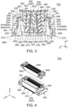
Fig. 3 is a cross-sectional view showing the connector assembly ofFig. 2 , taken along line A-A. In the figure, the circuit board is illustrated by dotted line. -
Fig. 4 is another perspective view showing the connector assembly ofFig. 1 . In the figure, the floating connector and the mating connector are in an unmated state where the floating connector and the mating connector are unmated with each other. -
Fig. 5 is a front view showing a part of the connector assembly ofFig. 4 . In the figure, the circuit board is illustrated by dotted line. -
Fig. 6 is a cross-sectional view showing the connector assembly ofFig. 5 , taken along line B-B. In the figure, the circuit board is illustrated by dotted line. -
Fig. 7 is an upper, perspective view showing a contact included in the floating connector of the connector assembly ofFig. 4 . -
Fig. 8 is a lower, perspective view showing the contact ofFig. 7 . -
Fig. 9 is a front view showing the contact ofFig. 7 . -
Fig. 10 is a rear view showing the contact ofFig. 7 . -
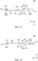
Fig. 11 is a top view showing the contact ofFig. 7 . -
Fig. 12 is a bottom view showing contact ofFig. 7 . -
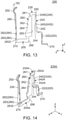
Fig. 13 is a side view showing the contact ofFig. 7 . -
Fig. 14 is an upper, perspective view showing a first modification of the contact ofFig. 7 . -
Fig. 15 is a lower, perspective view showing the contact ofFig. 14 . -
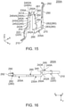
Fig. 16 is a top view showing the contact ofFig. 14 . -
Fig. 17 is a bottom view showing the contact ofFig. 14 . -
Fig. 18 is an upper, perspective view showing a contact row formed by several of the contacts ofFig. 14 . -
Fig. 19 is a rear view showing the contact row ofFig. 18 . -
Fig. 20 is a top view showing the contact row ofFig. 18 . -
Fig. 21 is an upper, perspective view showing a second modification of the contact ofFig. 7 . -
Fig. 22 is a lower, perspective view showing the contact ofFig. 21 . -
Fig. 23 is a top view showing the contact ofFig. 21 . -
Fig. 24 is a bottom view showing the contact ofFig. 21 . -
Fig. 25 is an upper, perspective view showing a third modification of the contact ofFig. 7 . -
Fig. 26 is a side view showing the contact ofFig. 25 . -
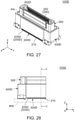
Fig. 27 is a perspective view showing a floating connector which is included in a connector assembly according to a second embodiment of the present invention. -
Fig. 28 is a front view showing a part of the floating connector ofFig. 27 . In the figure, a circuit board is illustrated by dotted line. -
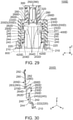
Fig. 29 is a cross-sectional view showing the floating connector ofFig. 28 , taken along line C-C. In the figure, the circuit board is illustrated by dotted line. -
Fig. 30 is an upper, perspective view showing a contact which is included in the floating connector ofFig. 27 . -
Fig. 31 is a lower, perspective view showing the contact ofFig. 30 . -
Fig. 32 is a front view showing the contact ofFig. 30 . -
Fig. 33 is a top view showing the contact ofFig. 30 . -
Fig. 34 is a bottom view showing the contact ofFig. 30 . -
Fig. 35 is a side view showing the contact ofFig. 30 . -
Fig. 36 is a cross-sectional view showing a floating connector of Patent Document 1. -
Fig. 37 is a perspective view showing a contact which is included in the floating connector ofFig. 36 . - While the invention is susceptible to various modifications and alternative forms, specific embodiments thereof are shown by way of example in the drawings and will herein be described in detail. It should be understood, however, that the drawings and detailed description thereto are not intended to limit the invention to the particular form disclosed, but on the contrary, the intention is to cover all modifications, equivalents and alternatives falling within the spirit and scope of the present invention as defined by the appended claims.
- As shown in
Fig. 4 , aconnector assembly 700 according to a first embodiment of the present invention comprises amating connector 600 and a floatingconnector 100. - As shown in
Fig. 6 , themating connector 600 of the present embodiment has amating housing 620 and a plurality ofmating contacts 605. - Referring to
Fig. 6 , themating housing 620 of the present embodiment is made of insulator. Themating housing 620 has a protrudingportion 622, a movable housingaccommodating portion 624 and amating surrounding portion 626. - As shown in
Fig. 6 , the protrudingportion 622 of the present embodiment protrudes downward in an up-down direction. The protrudingportion 622 is surrounded by themating surrounding portion 626 in a plane perpendicular to the up-down direction. The protrudingportion 622 is surrounded by the movable housingaccommodating portion 624 in the plane perpendicular to the up-down direction. In the present embodiment, the up-down direction is a Z-direction. Specifically, it is assumed that upward is a positive Z-direction while downward is a negative Z-direction. In the present embodiment, the plane perpendicular to the up-down direction is an XY-plane. - As shown in
Fig. 6 , the movable housingaccommodating portion 624 of the present embodiment is opened downward in the up-down direction. The movable housingaccommodating portion 624 is a space extending in the up-down direction. The movable housingaccommodating portion 624 is surrounded by themating surrounding portion 626 in the plane perpendicular to the up-down direction. - As shown in
Fig. 6 , themating surrounding portion 626 of the present embodiment surrounds the protrudingportion 622 in the plane perpendicular to the up-down direction. Themating surrounding portion 626 surrounds the movable housingaccommodating portion 624 in the plane perpendicular to the up-down direction. - As shown in
Fig. 4 , themating contacts 605 of the present embodiment are arranged in two rows in a horizontal direction perpendicular to the up-down direction. In the present embodiment, the horizontal direction is an X-direction. The horizontal direction is also a front-rear direction. Specifically, it is assumed that forward is a positive X-direction while rearward is a negative X-direction. Themating contacts 605 of each row are arranged in a pitch direction perpendicular to the up-down direction and the horizontal direction. In the present embodiment, the pitch direction is a Y-direction. - As shown in
Fig. 6 , themating contacts 605 are held by themating housing 620. More specifically, themating contacts 605 are held by the protrudingportion 622. In the movable housingaccommodating portion 624, a part of themating contact 605 is exposed to the outside of the protrudingportion 622 from a side surface of the protrudingportion 622 in the horizontal direction. Each of themating contacts 605 is made of metal. Each of themating contacts 605 has amating contact portion 610, amating extending portion 612 and a mating fixedportion 614. In other words, themating connector 600 has themating contact portions 610. - As shown in
Fig. 6 , themating contact portion 610 of the present embodiment faces outward in the horizontal direction. In the movable housingaccommodating portion 624, themating contact portion 610 is exposed to the outside of the protrudingportion 622 from the side surface of the protrudingportion 622 in the horizontal direction. Themating contact portion 610 is formed of a roll surface of a base metal plate. In other words, themating contact portion 610 is not a rough, broken face of a base metal plate. - As shown in
Fig. 6 , themating extending portion 612 of the present embodiment extends in the up-down direction. Themating extending portion 612 supports themating contact portion 610. - As shown in
Fig. 6 , the mating fixedportion 614 of the present embodiment extends outward in the horizontal direction from themating extending portion 612. The mating fixedportion 614 defines an upper end of themating contact 605 in the up-down direction. The mating fixedportion 614 defines an outer end of themating contact 605 in the horizontal direction. - As shown in
Figs. 3 and6 , the floatingconnector 100 of the present embodiment is used in a state where the floatingconnector 100 is mounted on acircuit board 800. In addition, the floatingconnector 100 is mateable with and removable from themating connector 600 having themating contact portions 610 along the up-down direction. - As shown in
Fig. 6 , the floatingconnector 100 of the present embodiment has amovable housing 300, a regulatingmember 400 and a plurality ofcontacts 200. - Referring to
Fig. 6 , themovable housing 300 of the present embodiment is made of insulator. Themovable housing 300 has a surroundingportion 302, anaccommodating portion 304 and abottom portion 306. - As shown in
Fig. 6 , the surroundingportion 302 of the present embodiment has a substantially rectangular tube shape extending in the up-down direction. - As shown in
Fig. 6 , theaccommodating portion 304 of the present embodiment is opened upward in the up-down direction. Theaccommodating portion 304 is surrounded by the surroundingportion 302 in the plane perpendicular to the up-down direction. As understood fromFigs. 3 and6 , theaccommodating portion 304 accommodates the protrudingportion 622 of themating connector 600 when the floatingconnector 100 and themating connector 600 are mated with each other. - As shown in
Fig. 6 , thebottom portion 306 of the present embodiment is positioned below theaccommodating portion 304 in the up-down direction. Thebottom portion 306 defines a lower end of themovable housing 300 in the up-down direction. Thebottom portion 306 has a plurality of holdingportions 320. In other words, themovable housing 300 has the holdingportions 320. - Referring to
Fig. 6 , each of the holdingportions 320 of the present embodiment is a set of two ditches each extending in the up-down direction. The holdingportions 320 correspond to thecontacts 200, respectively. Each of the ditches of the holdingportion 320 has an inner wall facing inward in the pitch direction. - Referring to
Fig. 6 , the regulatingmember 400 of the present embodiment is made of insulator. The regulatingmember 400 extends in the up-down direction. The regulatingmember 400 has a plurality of regulatingportions 420. - Referring to
Fig. 6 , the regulatingportions 420 of the present embodiment correspond to thecontacts 200, respectively. Each of the regulatingportions 420 is a ditch which is provided to the regulatingmember 400. Each of the regulatingportions 420 is positioned in the vicinity of an outer end of the regulatingmember 400 in the horizontal direction. Each of the regulatingportions 420 has two inner walls each facing inward in the pitch direction. - Referring to
Fig. 7 , each of thecontacts 200 of the present embodiment is made of asingle metal plate 205. Thecontact 200 is a so-called bent contact. Referring toFig. 6 , thecontacts 200 form twocontact rows contact rows contacts 200 of each of thecontact rows contact row 202 is positioned rearward of thecontact row 204 in the front-rear direction, or in the horizontal direction. - Hereinafter, explanation will be made about the
contact 200 included in thecontact row 202 as shown inFig. 6 . Thecontact 200, which is included in thecontact row 204 as shown inFig. 6 , has a structure same as that of thecontact 200, which is included in thecontact row 202, other than definitions of a first pitch orientation and a second pitch orientation as described below. Accordingly, a detailed explanation thereabout is omitted. - As shown in
Fig. 7 , each of thecontacts 200 of the present embodiment has a fixedportion 210, aregulated portion 220, a heldportion 280, an extendingportion 290, acontact portion 292 and acoupling portion 230. - As shown in
Fig. 6 , the fixedportion 210 of the present embodiment is fixed to thecircuit board 800 by soldering or the like when the floatingconnector 100 is mounted on thecircuit board 800. The fixedportion 210 extends downward from theregulated portion 220 and is bent to extend outward in the horizontal direction. The fixedportion 210 defines an outer end of thecontact 200 in the horizontal direction. The fixedportion 210 is positioned outward beyond themovable housing 300 in the horizontal direction. The fixedportion 210 is positioned outward beyond the surroundingportion 302 in the horizontal direction. - As shown in
Fig. 6 , theregulated portion 220 of the present embodiment extends upward in the up-down direction from the fixedportion 210. Theregulated portion 220 is positioned outward beyond themovable housing 300 in the horizontal direction. Theregulated portion 220 is positioned outward beyond the surroundingportion 302 in the horizontal direction. As shown inFig. 7 , theregulated portion 220 has a plurality ofprotrusions 222 each protruding outward in the pitch direction. - Referring to
Fig. 6 , a movement of theregulated portion 220 in the pitch direction perpendicular to the up-down direction is regulated by the regulatingportion 420. More specifically, theregulated portion 220 is held by the regulatingportion 420. Theregulated portion 220 is press-fit into the regulatingportion 420. Theprotrusion 222 of theregulated portion 220 bites into the inner wall of the ditch of the regulatingportion 420. More specifically, theprotrusion 222, which is positioned at a side of theregulated portion 220 in a first pitch orientation, bites into the inner wall which is positioned at a side of the ditch of the regulatingportion 420 in the first pitch orientation. Similarly, theprotrusion 222, which is positioned at a side of theregulated portion 220 in a second pitch orientation, bites into the inner wall which is positioned at a side of the ditch of the regulatingportion 420 in the second pitch orientation. In the present embodiment, the first pitch orientation is a positive Y-direction while the second pitch orientation is a negative Y-direction. Regarding thecontact 200 of thecontact row 204 as shown inFig. 6 , it is assumed that the first pitch orientation is the negative Y-direction while the second pitch orientation is the positive Y-direction. - As shown in
Fig. 6 , the heldportion 280 of the present embodiment extends upward in the up-down direction. The heldportion 280 is positioned below theaccommodating portion 304 in the up-down direction. The heldportion 280 is held by the holdingportion 320. More specifically, the heldportion 280 is press-fit into the holdingportion 320. In other words, thecontacts 200 are held by themovable housing 300. As shown inFig. 7 , the heldportion 280 has a plurality ofprotrusions 282 and a connectingportion 283. - Referring to
Figs. 6 and7 , each of theprotrusions 282 protrudes outward in the pitch direction. Theprotrusion 282 bites into the inner wall of the ditch of the holdingportion 320. More specifically, theprotrusion 282, which is positioned at a side of the heldportion 280 in the first pitch orientation, bites into the inner wall which is positioned at a side of the ditch of the holdingportion 320 in the first pitch orientation. Similarly, theprotrusion 282, which is positioned at a side of the heldportion 280 in the second pitch orientation, bites into the inner wall which is positioned at a side of the ditch of the holdingportion 320 in the second pitch orientation. - As shown in
Fig. 9 , the connectingportion 283 of the present embodiment defines a lower end of the heldportion 280 in the up-down direction. The connectingportion 283 has anend portion 2832 which faces in the first pitch orientation of the pitch direction. Theend portion 2832 is positioned in the second pitch orientation beyond theprotrusion 282 which is positioned at the side of the heldportion 280 in the first pitch orientation - Referring to
Fig. 13 , the extendingportion 290 of the present embodiment extends upward in the up-down direction from heldportion 280. The extendingportion 290 supports thecontact portion 292 so that thecontact portion 292 is movable. The extendingportion 290 is resiliently deformable in the horizontal direction. However, the present invention is not limited thereto. The extendingportion 290 may be configured to support thecontact portion 292 so that thecontact portion 292 is immovable, provided that themating contact portion 610 is configured to be resiliently movable. - Referring to
Fig. 13 , thecontact portion 292 of the present embodiment is supported by the extendingportion 290. More specifically, thecontact portion 292 is resiliently supported by the extendingportion 290 so as to be movable in the horizontal direction. As shown inFig. 6 , thecontact portion 292 is positioned in theaccommodating portion 304. As shown inFig. 3 , thecontact portion 292 is brought into contact with themating contact portion 610 when the floatingconnector 100 is mated with themating connector 600. Thecontact portion 292 is formed by bending a blank. Referring toFigs. 9 and13 , thecontact portion 292 has a first size S1 in the pitch direction and has a second size S2 in the horizontal direction perpendicular to both the pitch direction and the up-down direction. Specifically, the first size S1 is greater than the second size S2. A surface of thecontact portion 292, which is configured to be brought into contact with themating contact portion 610, is a roll surface of a base metal plate. In other words, the surface of thecontact portion 292, which is configured to be brought into contact with themating contact portion 610, is not a rough, broken face of a base metal plate. If the surface of thecontact portion 292, which is configured to be brought into contact with themating contact portion 610, is the rough, broken face, this causes problems as follows: a contact area is reduced between thecontact portion 292 and themating contact portion 610 by the rough, broken face of thecontact portion 292 being brought into contact with themating contact portion 610 upon mating of a floatingconnector 100 with themating connector 600; and thecontact portion 292 and themating contact portion 610 are abraded by the rough, broken face of thecontact portion 292 being brought into contact with themating contact portion 610 upon mating of the floatingconnector 100 with themating connector 600. In contrast, thecontact portion 292 of the present embodiment does not cause such a problem. - Referring to
Fig. 7 , thecoupling portion 230 of the present embodiment couples theregulated portion 220 and the heldportion 280 with each other. Referring toFigs. 4 and6 , thecoupling portion 230 is resiliently deformable, and themovable housing 300 is movable within a predetermined range PA in the plane perpendicular to the up-down direction by the resilient deformation of thecoupling portion 230. In other words, the resilient reformation of thecoupling portion 230 enables themovable housing 300 not only to be movable in the horizontal direction to some extent but also to be movable in the pitch direction to some extent. - As described above, the
regulated portion 220 is held by the regulatingportion 420. As compared with a floating connector in which a movement of theregulated portion 220 is simply regulated by the regulatingportion 420, this holding can suppress transmission of stress occurred by the resilient deformation of thecontact 200, which is caused by the movement of themovable housing 300, to the fixedportion 210 fixed to thecircuit board 800. Thus, the floatingconnector 100 of the present embodiment is configured so that the movement of themovable housing 300 hardly weakens the fixing of the fixedportion 210 to thecircuit board 800 by soldering or the like. - As shown in
Fig. 7 , thecoupling portion 230 of the present embodiment has afirst portion 260, asecond portion 240 and abent portion 250. Specifically, thebent portion 250 connects thefirst portion 260 and thesecond portion 240 with each other. - As shown in
Fig. 13 , thefirst portion 260 of the present embodiment is positioned between the heldportion 280 and thebent portion 250. Thefirst portion 260 has anupper end 261, aprincipal surface 262 and anend surface 263. - As shown in
Fig. 13 , theupper end 261 of the present embodiment is the uppermost end of thefirst portion 260 in the up-down direction. - As shown in
Fig. 13 , theprincipal surface 262 of the present embodiment faces in the pitch direction. In other words, a thickness direction of theprincipal surface 262 is the pitch direction. Theprincipal surface 262 intersects with the pitch direction. More specifically, theprincipal surface 262 is perpendicular to the pitch direction. Theprincipal surface 262 is a roll surface of a base metal plate. In other words, theprincipal surface 262 is not a rough, broken face of a base metal plate. - As shown in
Fig. 7 , theend surface 263 of the present embodiment faces in the horizontal direction. Theend surface 263 intersects with the horizontal direction. Theend surface 263 is a rough, broken face of a base metal plate. In other words, theend surface 263 is not a roll surface of a base metal plate. - As shown in
Fig. 13 , thefirst portion 260 has awide portion 264 and anarrow portion 266. Specifically, thewide portion 264 has a size greater than an average size of thefirst portion 260, and thenarrow portion 266 has a size smaller than the average size of thefirst portion 260. - As shown in
Fig. 13 , thewide portion 264 of the present embodiment is positioned below thebent portion 250 in the up-down direction. Thewide portion 264 extends downward from a lower end of thebent portion 250. In a plane parallel to theprincipal surface 262, thewide portion 264 has the size greater than the average size of thefirst portion 260. Thewide portion 264 extends in a plane which is defined by the up-down direction and the horizontal direction. As shown inFig. 6 , thewide portion 264 is positioned outward beyond themovable housing 300 in the horizontal direction. Thewide portion 264 is positioned outward beyond the surroundingportion 302 in the horizontal direction. - As shown in
Fig. 13 , thenarrow portion 266 of the present embodiment is positioned below thewide portion 264 in the up-down direction. Thenarrow portion 266 extends downward from a lower end of thewide portion 264. In the plane parallel to theprincipal surface 262, thenarrow portion 266 has the size smaller than the average size of thefirst portion 260. Specifically, in the plane parallel to theprincipal surface 262, thewide portion 264 is wider than thenarrow portion 266. Accordingly, thewide portion 264 has a reduced impedance in thefirst portion 260. This enables impedance of thefirst portion 260 to be adjusted at thewide portion 264. As shown inFig. 6 , thenarrow portion 266 is positioned below themovable housing 300 in the up-down direction. - As shown in
Fig. 8 , thesecond portion 240 of the present embodiment is positioned between theregulated portion 220 and thebent portion 250. Thesecond portion 240 couples theregulated portion 220 and thebent portion 250 with each other. As shown inFig. 6 , thesecond portion 240 is positioned outward beyond themovable housing 300 in the horizontal direction. Thesecond portion 240 is positioned outward beyond the surroundingportion 302 in the horizontal direction. As shown inFig. 8 again, thesecond portion 240 has anupper end 241, end surfaces 242, 243 and aprincipal surface 244. - As shown in
Fig. 8 , theupper end 241 of the present embodiment is the uppermost end of thesecond portion 240 in the up-down direction. - As shown in
Fig. 10 , the end surfaces 242, 243 of the present embodiment define opposite outward ends, respectively, of thesecond portion 240 in the pitch direction. Each of the end surfaces 242, 243 intersects with the pitch direction. The end surfaces 242 faces in the first pitch orientation of the pitch direction. Theend surface 243 faces in the second pitch orientation of the pitch direction. Theend surface 242 is positioned in the first pitch orientation beyond theend surface 243. Each of the end surfaces 242, 243 is a rough, broken face of a base metal plate. In other words, each of the end surfaces 242, 243 is not a roll surface of a base metal plate. - As shown in
Fig. 7 , theprincipal surface 244 of the present embodiment faces in the horizontal direction. In other words, a thickness direction of theprincipal surface 244 is the horizontal direction. Theprincipal surface 244 intersects with the horizontal direction. More specifically, theprincipal surface 244 is perpendicular to the horizontal direction. Theprincipal surface 244 is a roll surface of a base metal plate. In other words, theprincipal surface 244 is not a rough, broken face of a base metal plate. - Referring to
Fig. 7 , theprincipal surface 262 of thefirst portion 260 faces in a first direction. Theprincipal surface 244 of thesecond portion 240 faces in a second direction. Specifically, the first direction is different from the second direction. In other words, the thickness direction of thefirst portion 260 is different from the thickness direction of thesecond portion 240. More specifically, the direction in which theprincipal surface 262 of thefirst portion 260 faces is perpendicular to the direction in which theprincipal surface 244 of thesecond portion 240 faces. In other words, the thickness direction of thefirst portion 260 is perpendicular to the thickness direction of thesecond portion 240. Thus, the floatingconnector 100 of the present embodiment is configured so that, upon the movement of themovable housing 300, thesecond portion 240 is resiliently deformed in response to a horizontal directional component of the movement of themovable housing 300 while thefirst portion 260 is resiliently deformed in response to a pitch directional component of the movement of themovable housing 300. By this configuration, the floatingconnector 100 of the present embodiment can suppress occurrence of torsional stress in the heldportion 280 of thecontact 200 even when themovable housing 300 is moved in the pitch direction. - As shown in
Fig. 10 , thesecond portion 240 has alower portion 245 and anupper portion 246. Specifically, thelower portion 245 has a size greater than an average size of thesecond portion 240, and theupper portion 246 has a size smaller than the average size of thesecond portion 240. - As shown in
Fig. 13 thelower portion 245 of the present embodiment extends upward in the up-down direction from theregulated portion 220. Thelower portion 245 extends inward in the horizontal direction from theregulated portion 220. More specifically, thelower portion 245 is bent to extend inward in the horizontal direction from theregulated portion 220, and is bent to extend upward in the up-down direction and inward in the horizontal direction. As shown inFig. 10 , thelower portion 245 has twoend portions end portion 2452 is positioned in the first pitch orientation beyond theend portion 2454. Theend portion 2452 of thelower portion 245 is theend surface 242 of thesecond portion 240. - As shown in
Fig. 13 , theupper portion 246 of the present embodiment extends upward in the up-down direction from thelower portion 245. Theupper end 241 is also the uppermost end of theupper portion 246 in the up-down direction. As shown inFig. 10 , theupper portion 246 has twoend portions end portion 2462 is positioned in the first pitch orientation beyond theend portion 2464. - As shown in
Fig. 10 , theend portion 2462 of theupper portion 246 is positioned in the second pitch orientation beyond theend portion 2452 of thelower portion 245. Referring toFig. 8 , theend portion 2462 of theupper portion 246 is positioned in the second pitch orientation beyond thefirst portion 260. Theend portion 2462 of theupper portion 246 is positioned in the second pitch orientation beyond thewide portion 264. Theend portion 2462 of theupper portion 246 is positioned in the second pitch orientation beyond thenarrow portion 266. - As shown in
Fig. 10 , theend portion 2464 of theupper portion 246 is positioned at a position same as a position of theend portion 2454 of thelower portion 245 in the pitch direction. Referring toFig. 8 , theend portion 2464 of theupper portion 246 is positioned in the second pitch orientation beyond thefirst portion 260. Theend surface 243 of thesecond portion 240 consists of theend portion 2454 and theend portion 2464. - As shown in
Fig. 8 , thebent portion 250 of the present embodiment connects theupper end 261 of thefirst portion 260 and theupper end 241 of thesecond portion 240 with each other. Thebent portion 250 extends from theupper portion 246. In detail, thebent portion 250 extends in the first pitch orientation from theend portion 2462 of theupper portion 246 and is bent to extend inward in the horizontal direction. As shown inFig. 13 , thebent portion 250 is positioned above thefirst portion 260 in the up-down direction. Thebent portion 250 is positioned above thesecond portion 240 in the up-down direction. As shown inFig. 11 , thebent portion 250 overlaps with thelower portion 245 when thecontact 200 is viewed along the up-down direction. Thebent portion 250 is positioned between the end surfaces 242 and 243 of thesecond portion 240 in the pitch direction. This enables thebent portion 250 to be easily formed by bending the blank. Additionally, this enables thecontact row 202, 204 (seeFig. 6 ) to have a reduced size in the pitch direction to some extent. As shown inFig. 6 , thebent portion 250 is positioned outward beyond themovable housing 300 in the horizontal direction. Thebent portion 250 is positioned outward beyond the surroundingportion 302 in the horizontal direction. - As shown in
Fig. 7 , each of the fixedportion 210, theregulated portion 220 and theprincipal surface 244 of thesecond portion 240 intersects with the horizontal direction. Specifically, a part of the fixedportion 210, which extends upward, intersects with the horizontal direction. Additionally, theregulated portion 220 extends in a direction intersecting with the horizontal direction. Furthermore, theprincipal surface 244 of thesecond portion 240 faces in a direction intersecting with the horizontal direction. More specifically, the part of the fixedportion 210, which extends upward, is perpendicular to the horizontal direction, theregulated portion 220 extends in the direction perpendicular to the horizontal direction, and theprincipal surface 244 of thesecond portion 240 faces in the direction perpendicular to the pitch direction. This can prevent significant variation of impedance at a connecting part of the circuit board 800 (seeFig. 6 ) and thecontact 200 while thecontact 200 is provided with no other bent portion. - As shown in
Fig. 7 , thecoupling portion 230 of the present embodiment further has an additionalbent portion 270 which couples the heldportion 280 and thefirst portion 260 with each other. - As shown in
Fig. 7 , the additionalbent portion 270 of the present embodiment is positioned between the heldportion 280 and thefirst portion 260. The heldportion 280 is positioned between the additionalbent portion 270 and the extendingportion 290. The additionalbent portion 270 couples the heldportion 280 and thefirst portion 260 with each other. The additionalbent portion 270 couples the connectingportion 283 and thefirst portion 260 with each other. The additionalbent portion 270 extends in the horizontal direction from thefirst portion 260 and is bent to extend in the second pitch orientation. As shown inFig. 13 , the additionalbent portion 270 is positioned below the heldportion 280 in the up-down direction. The additionalbent portion 270 is positioned below thewide portion 264 in the up-down direction. The additionalbent portion 270 is positioned below thebent portion 250 in the up-down direction. The additionalbent portion 270 is positioned below thesecond portion 240 in the up-down direction. The additionalbent portion 270 is positioned below theregulated portion 220 in the up-down direction. As shown inFig. 6 , the additionalbent portion 270 is positioned below themovable housing 300 in the up-down direction. - As described above, the
contact 200 of the present embodiment has the additionalbent portion 270. This enables thecontact 200 to be configured so that, without modifying a shape of thesecond portion 240, thecontact portion 292 is formed of a roll surface of a base metal plate while thewide portion 264 used for impedance adjustment extends in a plane defined by the up-down direction and the horizontal direction. More specifically, if thecontact 200 has no additionalbent portion 270 but has thecontact portion 292 of a roll surface of a base metal plate, thefirst portion 260 of the thus-configuredcontact 200 necessarily extends in a plane defined by the up-down direction and the pitch direction. It is of disadvantage that the thus-configuredcontacts 200 are arranged at increased intervals because thewide portion 264 of thefirst portion 260 is wide. If the thus-configuredcontact 200, which has no additionalbent portion 270 but has thecontact portion 292 of is the roll surface, is modified so that a portion equivalent to thewide portion 264 is provided at thesecond portion 240 while thefirst portion 260 has nowide portion 264, the modifiedcontact 200 has disadvantage as follows: a part of the modifiedcontact 200 around the fixedportion 210 has an increased size and thereby impedances of a pad (not shown) of thecircuit board 800 and the fixedportion 210 might be mismatched with each other. In contrast, thecontact 200 of the present embodiment does not have the aforementioned disadvantages because thecontact 200 has the additionalbent portion 270. - Where the first embodiment of the present invention is described above, the
contact 200 of the present embodiment may be modified as follows. - Referring to
Fig. 14 , acontact 200A according to a first modification is made of asingle metal plate 205A. Thecontact 200A is a so-called bent contact. Thecontact 200A has a fixedportion 210, aregulated portion 220, a heldportion 280, an extendingportion 290, acontact portion 292 and acoupling portion 230A. Components of thecontact 200A other than thecoupling portion 230A have structures same as those of the first embodiment. Accordingly, a detailed explanation thereabout is omitted. - As shown in
Fig. 14 , thecoupling portion 230A of the present modification couples theregulated portion 220 and the heldportion 280 with each other. Thecoupling portion 230A is resiliently deformable. Thecoupling portion 230A has afirst portion 260, asecond portion 240A and abent portion 250A which connects thefirst portion 260 and thesecond portion 240A with each other. Thefirst portion 260 of the present modification has a structure same as that of thefirst portion 260 of the aforementioned first embodiment. Accordingly, a detailed explanation thereabout is omitted. - As shown in
Fig. 15 , thesecond portion 240A of the present modification has anupper end 241A, end surfaces 242A, 243A, aprincipal surface 244, alower portion 245 and anupper portion 246A. Specifically, thelower portion 245 has a size greater than an average size of thesecond portion 240A, and theupper portion 246A has a size smaller than the average size of thesecond portion 240A. Theprincipal surface 244 and thelower portion 245 of the present modification have structures same as those of theprincipal surface 244 and thelower portion 245 of the aforementioned first embodiment. Accordingly, a detailed explanation thereabout is omitted. - As shown in
Fig. 15 , theupper end 241A of the present modification is the uppermost end of thesecond portion 240A in the up-down direction. - As shown in
Fig. 15 , the end surfaces 242A, 243Aof the present modification define opposite outward ends, respectively, of thesecond portion 240A in the pitch direction. Each of the end surfaces 242A, 243A intersects with the pitch direction. Theend surface 242A faces in the first pitch orientation of the pitch direction. Theend surface 243A faces in the second pitch orientation of the pitch direction. Theend surface 242A is positioned in the first pitch orientation beyond theend surface 243A. Each of the end surfaces 242A, 243A is a rough, broken face of a base metal plate. In other words, each of the end surfaces 242A, 243A is not a roll surface of a base metal plate. - As shown in
Fig. 15 , theupper portion 246A of the present modification extends upward in the up-down direction from thelower portion 245. Theupper end 241A is the uppermost end of theupper portion 246A in the up-down direction. Theupper portion 246A has twoend portions end portion 2462A is positioned in the first pitch orientation beyond theend portion 2464A. - As shown in
Fig. 19 , theend portion 2462A of theupper portion 246A is positioned at a position same as a position of theend portion 2452 of thelower portion 245 in the pitch direction. Theend surface 242A of thesecond portion 240A consists of theend portion 2452 and theend portion 2462A. - As shown in
Fig. 19 , theend portion 2464A of theupper portion 246A is positioned in the first pitch orientation beyond theend portion 2454 of thelower portion 245. As shown inFig. 15 , theend portion 2464A of theupper portion 246A is positioned in the second pitch orientation beyond thefirst portion 260. Theend portion 2464A of theupper portion 246A is positioned in the second pitch orientation beyond awide portion 264. Theend portion 2464A of theupper portion 246A is positioned in the second pitch orientation beyond anarrow portion 266. - As shown in
Fig. 15 , thebent portion 250A of the present modification connects anupper end 261 of thefirst portion 260 and theupper end 241A of thesecond portion 240A with each other. Thebent portion 250A extends from theupper portion 246A. More specifically, thebent portion 250A extends in the first pitch orientation from theend portion 2462A of theupper portion 246A and is bent to extend inward in the horizontal direction. As shown inFig. 14 , thebent portion 250A is positioned above thefirst portion 260 in the up-down direction. Thebent portion 250A is positioned above thesecond portion 240A in the up-down direction. As shown inFig. 19 , thebent portion 250A is positioned outward beyond theend surface 242A which is positioned at a side of thesecond portion 240A in the pitch direction. In other words, thebent portion 250A is positioned outward in the pitch direction beyond theend surface 242A of thesecond portion 240A. More specifically, thebent portion 250A is positioned outward beyond theend portion 2452 which is positioned at a side of thelower portion 245 in the first pitch orientation. In other words, thebent portion 250A is positioned outward in the first pitch orientation beyond theend portion 2452 of thelower portion 245. - As shown in
Fig. 20 , thebent portion 250A of one of two of thecontacts 200A, which are adjacent to each other, overlaps with thesecond portion 240A of a remaining one of the twocontacts 200A when thecontact row 202A is viewed along the up-down direction. Specifically, thebent portion 250A of one of two of thecontacts 200A, which are adjacent to each other, overlaps with thelower portion 245 of a remaining one of the twocontacts 200A when thecontact row 202A is viewed along the up-down direction. More specifically, when thecontact row 202A is viewed along the up-down direction, thebent portion 250A of one of neighboring two of the contacts 200Athat is positioned in the second pitch orientation beyond a remaining one of the neighboring twocontacts 200A overlaps with thelower portion 245 of the remaining one thereof which is positioned in the first pitch orientation beyond the one thereof. - As understood from
Figs. 14 and20 , the aforementioned configuration of thebent portion 250A enables anend surface 263 of thefirst portion 260 and theprincipal surface 244 of thesecond portion 240A to be positioned away from each other in thecontact 200A itself. Thus, thecontact 200A can have improved high frequency characteristics. - Referring to
Fig. 22 , acontact 200B according to a second modification is made of asingle metal plate 205B. Thecontact 200B is a so-called bent contact. Thecontact 200B has a fixedportion 210, aregulated portion 220, a heldportion 280, an extendingportion 290, acontact portion 292 and acoupling portion 230B. Components of thecontact 200B other than thecoupling portion 230B have structures same as those of the first embodiment. Accordingly, a detailed explanation thereabout is omitted. - As shown in
Fig. 22 , thecoupling portion 230B of the present modification couples theregulated portion 220 and the heldportion 280 with each other. Thecoupling portion 230B is resiliently deformable. Thecoupling portion 230B has afirst portion 260, asecond portion 240B and abent portion 250B which connects thefirst portion 260 and thesecond portion 240B with each other. Thefirst portion 260 of the present modification has a structure same as that of thefirst portion 260 of the aforementioned first embodiment. Accordingly, a detailed explanation thereabout is omitted. - As shown in
Fig. 22 , thesecond portion 240B of the present modification has anupper end 241B, end surfaces 242B, 243B, aprincipal surface 244, alower portion 245 and anupper portion 246B. Specifically, thelower portion 245 has a size greater than an average size of thesecond portion 240B, and theupper portion 246B has a size smaller than the average size of thesecond portion 240B. Theprincipal surface 244 and thelower portion 245 of the present modification have structures same as those of theprincipal surface 244 and thelower portion 245 of the aforementioned first embodiment. Accordingly, a detailed explanation thereabout is omitted. - As shown in
Fig. 21 , theupper end 241B of the present modification is the uppermost end of thesecond portion 240B in the up-down direction. - As shown in
Fig. 21 , the end surfaces 242B, 243B of the present modification define opposite outward ends, respectively, of thesecond portion 240B in the pitch direction. Each of the end surfaces 242B, 243B intersects with the pitch direction. Theend surface 242B faces in the first pitch orientation of the pitch direction. Theend surface 243B faces in the second pitch orientation of the pitch direction. Theend surface 242B is positioned in the first pitch orientation beyond theend surface 243B. Each of the end surfaces 242B, 243B is a rough, broken face of a base metal plate. In other words, the end surfaces 242B, 243B is not a roll surface of a base metal plate. - As shown in
Fig. 21 , theupper portion 246B of the present modification extends upward in the up-down direction from thelower portion 245. Theupper end 241B is the uppermost end of theupper portion 246B in the up-down direction. Theupper portion 246B has twoend portions end portion 2462B is positioned in the first pitch orientation beyond theend portion 2464B. - As shown in
Fig. 21 , theend portion 2462B of theupper portion 246B is positioned at a position same as a position of theend portion 2452 of thelower portion 245 in the pitch direction. Theend surface 242B of thesecond portion 240B consists of theend portion 2452 and theend portion 2462B. - As shown in
Fig. 22 , theend portion 2464B of theupper portion 246B is positioned in the first pitch orientation beyond theend portion 2454 of thelower portion 245. Theend portion 2464B of theupper portion 246B is positioned in the first pitch orientation beyond thefirst portion 260. Theend portion 2464B of theupper portion 246B is positioned in the first pitch orientation beyond awide portion 264. Theend portion 2464B of theupper portion 246B is positioned in the first pitch orientation beyond anarrow portion 266. - As shown in
Fig. 21 , thebent portion 250B of the present modification connects anupper end 261 of thefirst portion 260 and theupper end 241B of thesecond portion 240B with each other. Thebent portion 250B extends from theupper portion 246B. More specifically, thebent portion 250B extends in the second pitch orientation from theend portion 2464B of theupper portion 246B and is bent to extend inward in the horizontal direction. Thebent portion 250B is positioned above thefirst portion 260 in the up-down direction. Thebent portion 250B is positioned above thesecond portion 240B in the up-down direction. - As shown in
Fig. 23 , thebent portion 250B overlaps with thelower portion 245 when thecontact 200B is viewed along the up-down direction. Thebent portion 250B is positioned between the end surfaces 242B and 243B of thesecond portion 240B in the pitch direction. This enables thebent portion 250B to be easily formed by bending a blank. Additionally, this enables a contact row (not shown) of thecontacts 200B to have a reduced size in the pitch direction to some extent. - Referring to
Fig. 25 , acontact 200C according to a third modification is made of asingle metal plate 205C. Thecontact 200C is a so-called bent contact. Thecontact 200C has a fixedportion 210, aregulated portion 220, a heldportion 280, an extendingportion 290, acontact portion 292 and acoupling portion 230C. Components of thecontact 200C other than thecoupling portion 230C have structures same as those of the first embodiment. Accordingly, a detailed explanation thereabout is omitted. - As shown in
Fig. 26 , thecoupling portion 230C of the present modification couples theregulated portion 220 and the heldportion 280 with each other. Thecoupling portion 230C is resiliently deformable. Thecoupling portion 230C has afirst portion 260C, asecond portion 240 and abent portion 250 which connects thefirst portion 260C and thesecond portion 240 with each other. Thesecond portion 240 and thebent portion 250 of the present modification have structures same as those of thesecond portion 240 and thebent portion 250 of the aforementioned first embodiment. Accordingly, a detailed explanation thereabout is omitted. - As shown in
Fig. 26 , thefirst portion 260C of the present modification has awide portion 264, anarrow portion 266C and astub protrusion 267. Specifically, thewide portion 264 has a size greater than an average size of thefirst portion 260C, and thenarrow portion 266C has a size smaller than the average size of thefirst portion 260C. Thestub protrusion 267 protrudes from thenarrow portion 266C. In other words, thecoupling portion 230C further has thestub protrusion 267 which protrudes from thenarrow portion 266C. Thestub protrusion 267 enables impedance of thefirst portion 260C to be further adjusted thereat. - Referring to
Fig. 27 , a connector assembly (not shown) according to a second embodiment of the present invention comprises a mating connector (not shown) and a floatingconnector 100D. The mating connector of the present embodiment has a structure similar to that of the mating connector of the aforementioned first embodiment. Accordingly, a detailed explanation thereabout is omitted. As for directions and orientations in the present embodiment, expressions same as those of the first embodiment will be used hereinbelow. - As shown in
Fig. 27 , the floatingconnector 100D of the present embodiment has amovable housing 300, a regulatingmember 400D and a plurality ofcontacts 200D. Themovable housing 300 of the present embodiment has a structure similar to that of themovable housing 300 of the aforementioned first embodiment. Accordingly, a detailed explanation thereabout is omitted. - Referring to
Fig. 27 , the regulatingmember 400D of the present embodiment is made of insulator. The regulatingmember 400D has a substantially rectangular tube shape extending in the up-down direction. As shown inFig. 29 , the regulatingmember 400D is positioned below themovable housing 300 in the up-down direction. The regulatingmember 400D has a plurality of regulatingportions 420D. - Referring to
Fig. 29 , the regulatingportions 420D of the present embodiment correspond to thecontacts 200D, respectively. Each of the regulatingportions 420D is a hole piercing the regulatingmember 400D. Each of the regulatingportions 420D is positioned in the vicinity of an outer end of the regulatingmember 400D in the horizontal direction. Each of the regulatingportions 420D has two inner walls each facing inward in the pitch direction. - Referring to
Fig. 30 , each of thecontacts 200D of the present embodiment is made of asingle metal plate 205D. Thecontact 200D is a so-called bent contact. Referring toFig. 29 , thecontacts 200D form twocontact rows contact rows contacts 200D of each of thecontact rows contact row 202D is positioned rearward of thecontact row 204D in the front-rear direction, or in the horizontal direction. - Hereinafter, explanation will be made about the
contact 200D included in thecontact row 202D as shown inFig. 29 . Thecontact 200D, which is included in thecontact row 204D as shown inFig. 29 , has a structure same as that of thecontact 200D, which is included in thecontact row 202D, other than definitions of the first pitch orientation and the second pitch orientation. Accordingly, a detailed explanation thereabout is omitted. - As shown in
Fig. 30 , thecontact 200D of the present embodiment has a fixedportion 210, aregulated portion 220, a heldportion 280, an extendingportion 290, acontact portion 292 and acoupling portion 230D. Components of thecontact 200D other than thecoupling portion 230D have structures same as those of thecontact 200 of the first embodiment. Accordingly, a detailed explanation thereabout is omitted. - As shown in
Fig. 35 , thecoupling portion 230D of the present embodiment couples theregulated portion 220 and the heldportion 280 with each other. As shown inFig. 29 , thecoupling portion 230D is positioned below themovable housing 300 in the up-down direction. Referring toFigs. 27 and35 , thecoupling portion 230D is resiliently deformable, and themovable housing 300 is movable within a predetermined range PA in the plane perpendicular to the up-down direction by the resilient deformation of thecoupling portion 230D. In other words, the resilient reformation of thecoupling portion 230D enables themovable housing 300 not only to be movable in the horizontal direction to some extent but also to be movable in the pitch direction to some extent. - As shown in
Fig. 35 , thecoupling portion 230D of the present embodiment has afirst portion 260D, asecond portion 240 and abent portion 250D. Specifically, thebent portion 250D connects thefirst portion 260D and thesecond portion 240 with each other. Thesecond portion 240 of the present embodiment has a structure same as that of thesecond portion 240 of thecontact 200 of the first embodiment. Accordingly, a detailed explanation thereabout is omitted. - As shown in
Fig. 35 , thefirst portion 260D of the present embodiment is positioned between the heldportion 280 and thebent portion 250D. Thefirst portion 260D has aprincipal surface 262D and anend surface 263D. - As shown in
Fig. 35 , theprincipal surface 262D of the present embodiment faces in the pitch direction. In other words, a thickness direction of theprincipal surface 262D is the pitch direction. Theprincipal surface 262D intersects with the pitch direction. More specifically, theprincipal surface 262D is perpendicular to the pitch direction. Theprincipal surface 262D is a roll surface of a base metal plate. In other words, theprincipal surface 262D is not a rough, broken face of a base metal plate. - As shown in
Fig. 32 , theend surface 263D of the present embodiment faces in the horizontal direction. Theend surface 263D intersects with the horizontal direction. Theend surface 263D is a rough, broken face of a base metal plate. In other words, theend surface 263D is not a roll surface of a base metal plate. - As shown in
Fig. 35 , thefirst portion 260D has anarrow portion 266D and awide portion 264D. Specifically, thenarrow portion 266D has a size smaller than an average size of thefirst portion 260D, and thewide portion 264D has a size greater than the average size of thefirst portion 260D. - As shown in
Fig. 35 , thenarrow portion 266D of the present embodiment is positioned below the heldportion 280 in the up-down direction. Thenarrow portion 266D is positioned above thewide portion 264D in the up-down direction. Thenarrow portion 266D extends upward from an upper end of thewide portion 264D. In a plane parallel to theprincipal surface 262D, thenarrow portion 266D has a size smaller than the average size of thefirst portion 260D. - As shown in
Fig. 35 , thewide portion 264D of the present embodiment is positioned above theregulated portion 220 in the up-down direction. Thewide portion 264D is positioned above thesecond portion 240 in the up-down direction. Thewide portion 264D is positioned above thebent portion 250D in the up-down direction. In the plane parallel to theprincipal surface 262D, thewide portion 264D has a size greater than the average size of thefirst portion 260D. Specifically, in the plane parallel to theprincipal surface 262D, thewide portion 264D is wider than thenarrow portion 266D. Accordingly, thewide portion 264D has a reduced impedance in thefirst portion 260D. - Referring to
Fig. 30 , theprincipal surface 262D of thefirst portion 260D faces in a first direction, and aprincipal surface 244 of thesecond portion 240 faces in a second direction. Specifically, the first direction is different from the second direction. In other words, a thickness direction of thefirst portion 260D is different from a thickness direction of thesecond portion 240. More specifically, the direction in which theprincipal surface 262D of thefirst portion 260D faces is perpendicular to the direction in which theprincipal surface 244 of thesecond portion 240 faces. In other words, the thickness direction of thefirst portion 260D is perpendicular to the thickness direction of thesecond portion 240. Thus, the floatingconnector 100D of the present embodiment is configured so that, upon the movement of themovable housing 300, thesecond portion 240 is resiliently deformed in response to a horizontal directional component of the movement of themovable housing 300 while thefirst portion 260D is resiliently deformed in response to a pitch directional component of the movement of themovable housing 300. By this configuration, the floatingconnector 100D of the present embodiment can suppress occurrence of torsional stress in the heldportion 280 of thecontact 200D even when themovable housing 300 is moved in the pitch direction. - As shown in
Fig. 31 , thebent portion 250D of the present embodiment connects thefirst portion 260D and anupper end 241 of thesecond portion 240 with each other. Thebent portion 250D extends from anupper portion 246. In detail, thebent portion 250D extends in the first pitch orientation from anend portion 2462 of theupper portion 246 and is bent to extend inward in the horizontal direction. As shown inFig. 35 , thebent portion 250D is positioned below thefirst portion 260D in the up-down direction. Thebent portion 250D is positioned above the second portion 240D in the up-down direction. As understood fromFigs. 31 and 32 , thebent portion 250D overlaps with alower portion 245 when thecontact 200D is viewed along the up-down direction. Thebent portion 250D is positioned betweenend surfaces second portion 240 in the pitch direction. This enables thebent portion 250D to be easily formed by bending a blank. Additionally, this enables thecontact row - As shown in
Fig. 35 , thecoupling portion 230D of the present embodiment further has an additionalbent portion 270D which couples the heldportion 280 and thefirst portion 260D with each other. - As shown in
Fig. 30 , the additionalbent portion 270D of the present embodiment is positioned between the heldportion 280 and thefirst portion 260D. The heldportion 280 is positioned between the additionalbent portion 270D and the extendingportion 290. The additionalbent portion 270D couples the heldportion 280 and thefirst portion 260D with each other. The additionalbent portion 270D couples a connectingportion 283 and thefirst portion 260D with each other. The additionalbent portion 270D extends outward in the horizontal direction from thefirst portion 260D and is bent to extend in the second pitch orientation. As shown inFig. 35 , the additionalbent portion 270D is positioned below the heldportion 280 in the up-down direction. The additionalbent portion 270D is positioned at a position same as a position of thenarrow portion 266D in the up-down direction. The additionalbent portion 270D is positioned above thewide portion 264D in the up-down direction. The additionalbent portion 270D is positioned above thebent portion 250D in the up-down direction. The additionalbent portion 270D is positioned above thesecond portion 240 in the up-down direction. The additionalbent portion 270D is positioned above theregulated portion 220 in the up-down direction. The additionalbent portion 270D is positioned above the fixedportion 210 in the up-down direction. - Although the specific explanation about the present invention is made above referring to the embodiments, the present invention is not limited thereto and is susceptible to various modifications and alternative forms. In addition, the above embodiments and variations may also be combined.
- While there has been described what is believed to be the preferred embodiment of the invention, those skilled in the art will recognize that other and further modifications may be made thereto without departing from the spirit of the invention, and it is intended to claim all such embodiments that fall within the true scope of the invention.
Claims (12)
- A floating connector used in a state where the floating connector is mounted on a circuit board, the floating connector being mateable with and removable from a mating connector along an up-down direction, the mating connector having a mating contact portion, wherein:the floating connector comprises a movable housing, a regulating member and a plurality of contacts;the movable housing has a holding portion;the regulating member has a regulating portion;each of the contacts is made of a single metal plate;each of the contacts has a fixed portion, a regulated portion, a held portion, an extending portion, a contact portion and a coupling portion;the fixed portion is configured to be fixed to the circuit board;a movement of the regulated portion in a pitch direction perpendicular to the up-down direction is regulated by the regulating portion;the held portion is held by the holding portion;the extending portion extends upward in the up-down direction from the held portion;the contact portion is supported by the extending portion;the coupling portion couples the regulated portion and the held portion with each other;the contact portion is brought into contact with the mating contact portion when the floating connector is mated with the mating connector;the coupling portion is resiliently deformable;the movable housing is movable within a predetermined range in a plane perpendicular to the up-down direction by the resilient deformation of the coupling portion;the coupling portion has a first portion, a second portion and a bent portion which connects the first portion and the second portion with each other;each of the first portion and second portion has a principal surface;the first portion is positioned between the held portion and the bent portion;the second portion is positioned between the regulated portion and the bent portion;the principal surface of the first portion faces in a first direction xthe principal surface of the second portion faces in a second direction; andthe first direction and the second direction are different from each other.
- The floating connector as recited in claim 1, wherein:the contact portion has a first size in the pitch direction;the contact portion has a second size in a horizontal direction perpendicular to both the pitch direction and the up-down direction; andthe first size is greater than the second size.
- The floating connector as recited in claim 2, wherein:the principal surface of the first portion faces in the pitch direction; andthe coupling portion has an additional bent portion which couples the held portion and the first portion with each other.
- The floating connector as recited in claim 3, wherein the held portion is positioned between the additional bent portion and the extending portion.
- The floating connector as recited in one of claims 1 to 4, wherein the first direction and the second direction are perpendicular to each other.
- The floating connector as recited in one of claims 1 to 5, wherein:the first portion has a wide portion and a narrow portion;the wide portion has a size greater than an average size of the first portion; andthe narrow portion has a size smaller than the average size of the first portion.
- The floating connector as recited in claim 6, wherein the coupling portion further has a stub protrusion which protrudes from the narrow portion.
- The floating connector as recited in one of claims 1 to 7, wherein each of the fixed portion, the regulated portion and the principal surface of the second portion intersects with the horizontal direction.
- The floating connector as recited in one of claims 1 to 8, wherein;
each of the first portion and the second portion has an upper end in the up-down direction; and
the bent portion connects the upper end of the first portion and the upper end of the second portion with each other. - The floating connector as recited in one of claims 1 to 9, wherein the extending portion supports the contact portion so that the contact portion is movable.
- The floating connector as recited in one of claims 1 to 10, wherein:the second portion has an end surface in the pitch direction;the bent portion is positioned outward beyond the end surface of the second portion in the pitch direction;the plurality of contacts form a contact row;the contacts of the contact row are arranged in the pitch direction; andwhen the contact row is viewed along the up-down direction, the bent portion of one of two of the contacts, which are adjacent to each other, overlaps with the second portion of a remaining one of the two contacts.
- The floating connector as recited in one of claims 1 to 10, wherein:the second portion has opposite end surfaces in the pitch direction;the bent portion is positioned between the opposite end surfaces of the second portion;the second portion has a lower portion and an upper portion;the lower portion has a size greater than an average size of the second portion;the upper portion has a size smaller than the average size of the second portion;the upper portion extends upward in the up-down direction from the lower portion;the bent portion extends from the upper portion; andthe bent portion overlaps with the lower portion when the contact is viewed along the up-down direction.
Applications Claiming Priority (1)
| Application Number | Priority Date | Filing Date | Title |
|---|---|---|---|
| JP2020121509A JP7557983B2 (en) | 2020-07-15 | 2020-07-15 | Floating Connector |
Publications (2)
| Publication Number | Publication Date |
|---|---|
| EP3940890A1 true EP3940890A1 (en) | 2022-01-19 |
| EP3940890B1 EP3940890B1 (en) | 2023-03-01 |
Family
ID=75887835
Family Applications (1)
| Application Number | Title | Priority Date | Filing Date |
|---|---|---|---|
| EP21172912.4A Active EP3940890B1 (en) | 2020-07-15 | 2021-05-08 | Floating connector |
Country Status (5)
| Country | Link |
|---|---|
| US (1) | US11552420B2 (en) |
| EP (1) | EP3940890B1 (en) |
| JP (1) | JP7557983B2 (en) |
| CN (1) | CN113948893B (en) |
| TW (1) | TWI796677B (en) |
Families Citing this family (13)
| Publication number | Priority date | Publication date | Assignee | Title |
|---|---|---|---|---|
| USD950500S1 (en) * | 2018-12-17 | 2022-05-03 | Samtec, Inc. | Connector |
| JP6687790B1 (en) * | 2019-07-26 | 2020-04-28 | 京セラ株式会社 | Connector and electronic equipment |
| US11641073B2 (en) * | 2020-10-12 | 2023-05-02 | Japan Aviation Electronics Industry, Limited | Connector |
| JP7732917B2 (en) * | 2022-02-03 | 2025-09-02 | ヒロセ電機株式会社 | Electrical Connectors for Circuit Boards |
| JP7887265B2 (en) * | 2022-03-18 | 2026-07-09 | イリソ電子工業株式会社 | connector |
| JP7799523B2 (en) * | 2022-03-18 | 2026-01-15 | イリソ電子工業株式会社 | connector |
| JP7854318B2 (en) * | 2022-03-22 | 2026-05-01 | 日本航空電子工業株式会社 | Floating connector |
| CN114784533A (en) * | 2022-04-08 | 2022-07-22 | 厦门广泓工贸有限公司 | Electric connector and floating connector |
| JP7811357B2 (en) * | 2022-04-11 | 2026-02-05 | 日本航空電子工業株式会社 | connector |
| US20260005457A1 (en) * | 2022-07-08 | 2026-01-01 | Kyocera Corporation | Connector and electronic device |
| JP2024081331A (en) * | 2022-12-06 | 2024-06-18 | タイコエレクトロニクスジャパン合同会社 | Contact, connector, and connector assembly |
| JP2025163472A (en) * | 2024-04-17 | 2025-10-29 | 株式会社オートネットワーク技術研究所 | Terminal fittings and connectors |
| JP2025163453A (en) * | 2024-04-17 | 2025-10-29 | 株式会社オートネットワーク技術研究所 | Terminal fittings and connectors |
Citations (4)
| Publication number | Priority date | Publication date | Assignee | Title |
|---|---|---|---|---|
| JP2619334B2 (en) * | 1994-06-30 | 1997-06-11 | 大宏電機株式会社 | Printed circuit board connector |
| JP2018116825A (en) | 2017-01-18 | 2018-07-26 | 日本航空電子工業株式会社 | connector |
| US20180337482A1 (en) * | 2017-05-19 | 2018-11-22 | Molex, Llc | Connector and connector assembly |
| JP2018195567A (en) * | 2017-05-19 | 2018-12-06 | モレックス エルエルシー | Connectors and connector assemblies |
Family Cites Families (14)
| Publication number | Priority date | Publication date | Assignee | Title |
|---|---|---|---|---|
| JPH0817526B2 (en) | 1987-08-28 | 1996-02-21 | 日本電信電話株式会社 | Grip body attachment device |
| JPH0256373U (en) * | 1988-10-19 | 1990-04-24 | ||
| JP2005093424A (en) | 2003-08-08 | 2005-04-07 | Jst Mfg Co Ltd | Floating connector |
| US9281594B2 (en) * | 2012-09-05 | 2016-03-08 | Iriso Electronics Co., Ltd. | Connector |
| JP5499191B1 (en) * | 2013-01-28 | 2014-05-21 | 日本航空電子工業株式会社 | connector |
| JP6297928B2 (en) | 2014-06-02 | 2018-03-20 | 富士通コンポーネント株式会社 | connector |
| JP5941515B2 (en) | 2014-10-15 | 2016-06-29 | イリソ電子工業株式会社 | connector |
| JP6408106B1 (en) | 2017-10-25 | 2018-10-17 | 京セラ株式会社 | Connectors and electronic devices |
| US10096914B1 (en) | 2017-11-16 | 2018-10-09 | Greenconn Corp. | Floating connector and conductive terminal thereof |
| JP2019192527A (en) | 2018-04-26 | 2019-10-31 | ヒロセ電機株式会社 | Circuit board electrical connector |
| JP7093283B2 (en) * | 2018-10-04 | 2022-06-29 | 日本航空電子工業株式会社 | connector |
| JP7207975B2 (en) * | 2018-11-29 | 2023-01-18 | イリソ電子工業株式会社 | connector |
| JP6629417B2 (en) | 2018-12-07 | 2020-01-15 | 京セラ株式会社 | Connectors and electronic equipment |
| TWM593671U (en) * | 2019-09-12 | 2020-04-11 | 格稜股份有限公司 | Floating connector and conductivity terminal thereof |
-
2020
- 2020-07-15 JP JP2020121509A patent/JP7557983B2/en active Active
-
2021
- 2021-04-28 TW TW110115273A patent/TWI796677B/en active
- 2021-04-29 US US17/243,793 patent/US11552420B2/en active Active
- 2021-05-07 CN CN202110497560.2A patent/CN113948893B/en active Active
- 2021-05-08 EP EP21172912.4A patent/EP3940890B1/en active Active
Patent Citations (4)
| Publication number | Priority date | Publication date | Assignee | Title |
|---|---|---|---|---|
| JP2619334B2 (en) * | 1994-06-30 | 1997-06-11 | 大宏電機株式会社 | Printed circuit board connector |
| JP2018116825A (en) | 2017-01-18 | 2018-07-26 | 日本航空電子工業株式会社 | connector |
| US20180337482A1 (en) * | 2017-05-19 | 2018-11-22 | Molex, Llc | Connector and connector assembly |
| JP2018195567A (en) * | 2017-05-19 | 2018-12-06 | モレックス エルエルシー | Connectors and connector assemblies |
Also Published As
| Publication number | Publication date |
|---|---|
| JP2022018414A (en) | 2022-01-27 |
| CN113948893A (en) | 2022-01-18 |
| TW202205759A (en) | 2022-02-01 |
| CN113948893B (en) | 2024-11-22 |
| EP3940890B1 (en) | 2023-03-01 |
| TWI796677B (en) | 2023-03-21 |
| US11552420B2 (en) | 2023-01-10 |
| US20220021143A1 (en) | 2022-01-20 |
| JP7557983B2 (en) | 2024-09-30 |
Similar Documents
| Publication | Publication Date | Title |
|---|---|---|
| EP3940890B1 (en) | Floating connector | |
| CN102427177B (en) | Contact and electrical connector | |
| JP7109303B2 (en) | connector assembly | |
| JP7467236B2 (en) | Floating Connector | |
| US8277264B2 (en) | Contact having independently deformable spring portions and connector including the contact | |
| US20220115799A1 (en) | Connector | |
| US8057247B2 (en) | Contact and electrical connector | |
| EP3467948B1 (en) | Connector | |
| CN115207669B (en) | Connectors | |
| JP2018022551A (en) | Female terminal and connector with the same | |
| US12136780B2 (en) | Connector comprising a terminal with an arm having a base portion extending alongside a contact poriton | |
| US12218464B2 (en) | Connector assembly having a mating connector and a connector configured to be mounted on an object wherein an abutment portion of a supporting portion of a terminal of the connector is in contact with a receiving portion of a coupling portion of the terminal under a mated state | |
| US9022817B2 (en) | Connector terminal including limiter extending along first and second spring terminals | |
| KR20050065388A (en) | Electrical connector and electrical connector assembly | |
| KR101221840B1 (en) | connector | |
| JP2023093120A (en) | Connectors and connector assemblies | |
| TWI850993B (en) | Floating connector | |
| US6200174B1 (en) | Connecting terminal | |
| KR20040029265A (en) | Connector in which contact force can be maintained during a long period | |
| JP2025021704A (en) | connector | |
| KR20250015982A (en) | Female/male fitting type electric connector | |
| JP2024127273A (en) | Electrical Connectors for Circuit Boards |
Legal Events
| Date | Code | Title | Description |
|---|---|---|---|
| PUAI | Public reference made under article 153(3) epc to a published international application that has entered the european phase |
Free format text: ORIGINAL CODE: 0009012 |
|
| STAA | Information on the status of an ep patent application or granted ep patent |
Free format text: STATUS: THE APPLICATION HAS BEEN PUBLISHED |
|
| AK | Designated contracting states |
Kind code of ref document: A1 Designated state(s): AL AT BE BG CH CY CZ DE DK EE ES FI FR GB GR HR HU IE IS IT LI LT LU LV MC MK MT NL NO PL PT RO RS SE SI SK SM TR |
|
| STAA | Information on the status of an ep patent application or granted ep patent |
Free format text: STATUS: REQUEST FOR EXAMINATION WAS MADE |
|
| 17P | Request for examination filed |
Effective date: 20220217 |
|
| RBV | Designated contracting states (corrected) |
Designated state(s): AL AT BE BG CH CY CZ DE DK EE ES FI FR GB GR HR HU IE IS IT LI LT LU LV MC MK MT NL NO PL PT RO RS SE SI SK SM TR |
|
| STAA | Information on the status of an ep patent application or granted ep patent |
Free format text: STATUS: EXAMINATION IS IN PROGRESS |
|
| 17Q | First examination report despatched |
Effective date: 20220405 |
|
| GRAP | Despatch of communication of intention to grant a patent |
Free format text: ORIGINAL CODE: EPIDOSNIGR1 |
|
| STAA | Information on the status of an ep patent application or granted ep patent |
Free format text: STATUS: GRANT OF PATENT IS INTENDED |
|
| RIC1 | Information provided on ipc code assigned before grant |
Ipc: H01R 12/70 20110101ALN20220901BHEP Ipc: H01R 13/24 20060101ALI20220901BHEP Ipc: H01R 12/55 20110101ALI20220901BHEP Ipc: H01R 12/71 20110101ALI20220901BHEP Ipc: H01R 12/91 20110101AFI20220901BHEP |
|
| INTG | Intention to grant announced |
Effective date: 20220921 |
|
| GRAS | Grant fee paid |
Free format text: ORIGINAL CODE: EPIDOSNIGR3 |
|
| GRAA | (expected) grant |
Free format text: ORIGINAL CODE: 0009210 |
|
| STAA | Information on the status of an ep patent application or granted ep patent |
Free format text: STATUS: THE PATENT HAS BEEN GRANTED |
|
| AK | Designated contracting states |
Kind code of ref document: B1 Designated state(s): AL AT BE BG CH CY CZ DE DK EE ES FI FR GB GR HR HU IE IS IT LI LT LU LV MC MK MT NL NO PL PT RO RS SE SI SK SM TR |
|
| REG | Reference to a national code |
Ref country code: GB Ref legal event code: FG4D |
|
| REG | Reference to a national code |
Ref country code: CH Ref legal event code: EP Ref country code: AT Ref legal event code: REF Ref document number: 1551660 Country of ref document: AT Kind code of ref document: T Effective date: 20230315 |
|
| REG | Reference to a national code |
Ref country code: DE Ref legal event code: R096 Ref document number: 602021001495 Country of ref document: DE |
|
| REG | Reference to a national code |
Ref country code: IE Ref legal event code: FG4D |
|
| REG | Reference to a national code |
Ref country code: LT Ref legal event code: MG9D |
|
| REG | Reference to a national code |
Ref country code: NL Ref legal event code: MP Effective date: 20230301 |
|
| PG25 | Lapsed in a contracting state [announced via postgrant information from national office to epo] |
Ref country code: RS Free format text: LAPSE BECAUSE OF FAILURE TO SUBMIT A TRANSLATION OF THE DESCRIPTION OR TO PAY THE FEE WITHIN THE PRESCRIBED TIME-LIMIT Effective date: 20230301 Ref country code: NO Free format text: LAPSE BECAUSE OF FAILURE TO SUBMIT A TRANSLATION OF THE DESCRIPTION OR TO PAY THE FEE WITHIN THE PRESCRIBED TIME-LIMIT Effective date: 20230601 Ref country code: LV Free format text: LAPSE BECAUSE OF FAILURE TO SUBMIT A TRANSLATION OF THE DESCRIPTION OR TO PAY THE FEE WITHIN THE PRESCRIBED TIME-LIMIT Effective date: 20230301 Ref country code: LT Free format text: LAPSE BECAUSE OF FAILURE TO SUBMIT A TRANSLATION OF THE DESCRIPTION OR TO PAY THE FEE WITHIN THE PRESCRIBED TIME-LIMIT Effective date: 20230301 Ref country code: HR Free format text: LAPSE BECAUSE OF FAILURE TO SUBMIT A TRANSLATION OF THE DESCRIPTION OR TO PAY THE FEE WITHIN THE PRESCRIBED TIME-LIMIT Effective date: 20230301 Ref country code: ES Free format text: LAPSE BECAUSE OF FAILURE TO SUBMIT A TRANSLATION OF THE DESCRIPTION OR TO PAY THE FEE WITHIN THE PRESCRIBED TIME-LIMIT Effective date: 20230301 |
|
| REG | Reference to a national code |
Ref country code: AT Ref legal event code: MK05 Ref document number: 1551660 Country of ref document: AT Kind code of ref document: T Effective date: 20230301 |
|
| PG25 | Lapsed in a contracting state [announced via postgrant information from national office to epo] |
Ref country code: SE Free format text: LAPSE BECAUSE OF FAILURE TO SUBMIT A TRANSLATION OF THE DESCRIPTION OR TO PAY THE FEE WITHIN THE PRESCRIBED TIME-LIMIT Effective date: 20230301 Ref country code: PL Free format text: LAPSE BECAUSE OF FAILURE TO SUBMIT A TRANSLATION OF THE DESCRIPTION OR TO PAY THE FEE WITHIN THE PRESCRIBED TIME-LIMIT Effective date: 20230301 Ref country code: NL Free format text: LAPSE BECAUSE OF FAILURE TO SUBMIT A TRANSLATION OF THE DESCRIPTION OR TO PAY THE FEE WITHIN THE PRESCRIBED TIME-LIMIT Effective date: 20230301 Ref country code: GR Free format text: LAPSE BECAUSE OF FAILURE TO SUBMIT A TRANSLATION OF THE DESCRIPTION OR TO PAY THE FEE WITHIN THE PRESCRIBED TIME-LIMIT Effective date: 20230602 Ref country code: FI Free format text: LAPSE BECAUSE OF FAILURE TO SUBMIT A TRANSLATION OF THE DESCRIPTION OR TO PAY THE FEE WITHIN THE PRESCRIBED TIME-LIMIT Effective date: 20230301 |
|
| PG25 | Lapsed in a contracting state [announced via postgrant information from national office to epo] |
Ref country code: SM Free format text: LAPSE BECAUSE OF FAILURE TO SUBMIT A TRANSLATION OF THE DESCRIPTION OR TO PAY THE FEE WITHIN THE PRESCRIBED TIME-LIMIT Effective date: 20230301 Ref country code: RO Free format text: LAPSE BECAUSE OF FAILURE TO SUBMIT A TRANSLATION OF THE DESCRIPTION OR TO PAY THE FEE WITHIN THE PRESCRIBED TIME-LIMIT Effective date: 20230301 Ref country code: PT Free format text: LAPSE BECAUSE OF FAILURE TO SUBMIT A TRANSLATION OF THE DESCRIPTION OR TO PAY THE FEE WITHIN THE PRESCRIBED TIME-LIMIT Effective date: 20230703 Ref country code: EE Free format text: LAPSE BECAUSE OF FAILURE TO SUBMIT A TRANSLATION OF THE DESCRIPTION OR TO PAY THE FEE WITHIN THE PRESCRIBED TIME-LIMIT Effective date: 20230301 Ref country code: CZ Free format text: LAPSE BECAUSE OF FAILURE TO SUBMIT A TRANSLATION OF THE DESCRIPTION OR TO PAY THE FEE WITHIN THE PRESCRIBED TIME-LIMIT Effective date: 20230301 Ref country code: AT Free format text: LAPSE BECAUSE OF FAILURE TO SUBMIT A TRANSLATION OF THE DESCRIPTION OR TO PAY THE FEE WITHIN THE PRESCRIBED TIME-LIMIT Effective date: 20230301 |
|
| PG25 | Lapsed in a contracting state [announced via postgrant information from national office to epo] |
Ref country code: SK Free format text: LAPSE BECAUSE OF FAILURE TO SUBMIT A TRANSLATION OF THE DESCRIPTION OR TO PAY THE FEE WITHIN THE PRESCRIBED TIME-LIMIT Effective date: 20230301 Ref country code: IS Free format text: LAPSE BECAUSE OF FAILURE TO SUBMIT A TRANSLATION OF THE DESCRIPTION OR TO PAY THE FEE WITHIN THE PRESCRIBED TIME-LIMIT Effective date: 20230701 |
|
| REG | Reference to a national code |
Ref country code: DE Ref legal event code: R097 Ref document number: 602021001495 Country of ref document: DE |
|
| PLBE | No opposition filed within time limit |
Free format text: ORIGINAL CODE: 0009261 |
|
| STAA | Information on the status of an ep patent application or granted ep patent |
Free format text: STATUS: NO OPPOSITION FILED WITHIN TIME LIMIT |
|
| PG25 | Lapsed in a contracting state [announced via postgrant information from national office to epo] |
Ref country code: MC Free format text: LAPSE BECAUSE OF FAILURE TO SUBMIT A TRANSLATION OF THE DESCRIPTION OR TO PAY THE FEE WITHIN THE PRESCRIBED TIME-LIMIT Effective date: 20230301 |
|
| REG | Reference to a national code |
Ref country code: BE Ref legal event code: MM Effective date: 20230531 |
|
| PG25 | Lapsed in a contracting state [announced via postgrant information from national office to epo] |
Ref country code: SI Free format text: LAPSE BECAUSE OF FAILURE TO SUBMIT A TRANSLATION OF THE DESCRIPTION OR TO PAY THE FEE WITHIN THE PRESCRIBED TIME-LIMIT Effective date: 20230301 Ref country code: MC Free format text: LAPSE BECAUSE OF FAILURE TO SUBMIT A TRANSLATION OF THE DESCRIPTION OR TO PAY THE FEE WITHIN THE PRESCRIBED TIME-LIMIT Effective date: 20230301 Ref country code: LU Free format text: LAPSE BECAUSE OF NON-PAYMENT OF DUE FEES Effective date: 20230508 Ref country code: DK Free format text: LAPSE BECAUSE OF FAILURE TO SUBMIT A TRANSLATION OF THE DESCRIPTION OR TO PAY THE FEE WITHIN THE PRESCRIBED TIME-LIMIT Effective date: 20230301 |
|
| 26N | No opposition filed |
Effective date: 20231204 |
|
| REG | Reference to a national code |
Ref country code: IE Ref legal event code: MM4A |
|
| PG25 | Lapsed in a contracting state [announced via postgrant information from national office to epo] |
Ref country code: IE Free format text: LAPSE BECAUSE OF NON-PAYMENT OF DUE FEES Effective date: 20230508 |
|
| PG25 | Lapsed in a contracting state [announced via postgrant information from national office to epo] |
Ref country code: IE Free format text: LAPSE BECAUSE OF NON-PAYMENT OF DUE FEES Effective date: 20230508 |
|
| PG25 | Lapsed in a contracting state [announced via postgrant information from national office to epo] |
Ref country code: IT Free format text: LAPSE BECAUSE OF FAILURE TO SUBMIT A TRANSLATION OF THE DESCRIPTION OR TO PAY THE FEE WITHIN THE PRESCRIBED TIME-LIMIT Effective date: 20230301 Ref country code: BE Free format text: LAPSE BECAUSE OF NON-PAYMENT OF DUE FEES Effective date: 20230531 |
|
| PG25 | Lapsed in a contracting state [announced via postgrant information from national office to epo] |
Ref country code: BG Free format text: LAPSE BECAUSE OF FAILURE TO SUBMIT A TRANSLATION OF THE DESCRIPTION OR TO PAY THE FEE WITHIN THE PRESCRIBED TIME-LIMIT Effective date: 20230301 |
|
| PG25 | Lapsed in a contracting state [announced via postgrant information from national office to epo] |
Ref country code: BG Free format text: LAPSE BECAUSE OF FAILURE TO SUBMIT A TRANSLATION OF THE DESCRIPTION OR TO PAY THE FEE WITHIN THE PRESCRIBED TIME-LIMIT Effective date: 20230301 |
|
| REG | Reference to a national code |
Ref country code: CH Ref legal event code: PL |
|
| PG25 | Lapsed in a contracting state [announced via postgrant information from national office to epo] |
Ref country code: CH Free format text: LAPSE BECAUSE OF NON-PAYMENT OF DUE FEES Effective date: 20240531 |
|
| PG25 | Lapsed in a contracting state [announced via postgrant information from national office to epo] |
Ref country code: CY Free format text: LAPSE BECAUSE OF FAILURE TO SUBMIT A TRANSLATION OF THE DESCRIPTION OR TO PAY THE FEE WITHIN THE PRESCRIBED TIME-LIMIT; INVALID AB INITIO Effective date: 20210508 |
|
| PG25 | Lapsed in a contracting state [announced via postgrant information from national office to epo] |
Ref country code: HU Free format text: LAPSE BECAUSE OF FAILURE TO SUBMIT A TRANSLATION OF THE DESCRIPTION OR TO PAY THE FEE WITHIN THE PRESCRIBED TIME-LIMIT; INVALID AB INITIO Effective date: 20210508 |
|
| PG25 | Lapsed in a contracting state [announced via postgrant information from national office to epo] |
Ref country code: TR Free format text: LAPSE BECAUSE OF FAILURE TO SUBMIT A TRANSLATION OF THE DESCRIPTION OR TO PAY THE FEE WITHIN THE PRESCRIBED TIME-LIMIT Effective date: 20230301 |
|
| GBPC | Gb: european patent ceased through non-payment of renewal fee |
Effective date: 20250508 |
|
| PG25 | Lapsed in a contracting state [announced via postgrant information from national office to epo] |
Ref country code: GB Free format text: LAPSE BECAUSE OF NON-PAYMENT OF DUE FEES Effective date: 20250508 |
|
| PG25 | Lapsed in a contracting state [announced via postgrant information from national office to epo] |
Ref country code: CH Free format text: THE PATENT HAS BEEN ANNULLED BY A DECISION OF A NATIONAL AUTHORITY Effective date: 20240531 |
|
| PGFP | Annual fee paid to national office [announced via postgrant information from national office to epo] |
Ref country code: DE Payment date: 20260402 Year of fee payment: 6 |
|
| PG25 | Lapsed in a contracting state [announced via postgrant information from national office to epo] |
Ref country code: MT Free format text: LAPSE BECAUSE OF NON-PAYMENT OF DUE FEES Effective date: 20230508 |
|
| PGFP | Annual fee paid to national office [announced via postgrant information from national office to epo] |
Ref country code: FR Payment date: 20260401 Year of fee payment: 6 |