EP3940855A1 - Electrode assembly and battery - Google Patents
Electrode assembly and battery Download PDFInfo
- Publication number
- EP3940855A1 EP3940855A1 EP20864327.0A EP20864327A EP3940855A1 EP 3940855 A1 EP3940855 A1 EP 3940855A1 EP 20864327 A EP20864327 A EP 20864327A EP 3940855 A1 EP3940855 A1 EP 3940855A1
- Authority
- EP
- European Patent Office
- Prior art keywords
- electrode plate
- electrode assembly
- winding
- electrode
- terminating end
- Prior art date
- Legal status (The legal status is an assumption and is not a legal conclusion. Google has not performed a legal analysis and makes no representation as to the accuracy of the status listed.)
- Pending
Links
- 238000004804 winding Methods 0.000 claims abstract description 87
- 239000011888 foil Substances 0.000 claims abstract description 60
- 239000011149 active material Substances 0.000 claims abstract description 32
- 239000000853 adhesive Substances 0.000 claims description 24
- 230000001070 adhesive effect Effects 0.000 claims description 24
- 238000002844 melting Methods 0.000 claims description 6
- 230000008018 melting Effects 0.000 claims description 6
- 239000004831 Hot glue Substances 0.000 claims description 4
- XAGFODPZIPBFFR-UHFFFAOYSA-N aluminium Chemical compound [Al] XAGFODPZIPBFFR-UHFFFAOYSA-N 0.000 abstract description 27
- 229910052782 aluminium Inorganic materials 0.000 abstract description 27
- HBBGRARXTFLTSG-UHFFFAOYSA-N Lithium ion Chemical compound [Li+] HBBGRARXTFLTSG-UHFFFAOYSA-N 0.000 abstract description 5
- 229910001416 lithium ion Inorganic materials 0.000 abstract description 5
- 230000000052 comparative effect Effects 0.000 description 18
- 238000010586 diagram Methods 0.000 description 9
- 239000011248 coating agent Substances 0.000 description 6
- 238000000576 coating method Methods 0.000 description 6
- 238000004519 manufacturing process Methods 0.000 description 4
- 230000000712 assembly Effects 0.000 description 3
- 238000000429 assembly Methods 0.000 description 3
- WHXSMMKQMYFTQS-UHFFFAOYSA-N Lithium Chemical compound [Li] WHXSMMKQMYFTQS-UHFFFAOYSA-N 0.000 description 2
- 230000002687 intercalation Effects 0.000 description 2
- 238000009830 intercalation Methods 0.000 description 2
- 229910052744 lithium Inorganic materials 0.000 description 2
- 238000012986 modification Methods 0.000 description 2
- 230000004048 modification Effects 0.000 description 2
- 238000007789 sealing Methods 0.000 description 2
- 230000000391 smoking effect Effects 0.000 description 2
- 239000000126 substance Substances 0.000 description 2
- 238000006467 substitution reaction Methods 0.000 description 2
- OKTJSMMVPCPJKN-UHFFFAOYSA-N Carbon Chemical compound [C] OKTJSMMVPCPJKN-UHFFFAOYSA-N 0.000 description 1
- RYGMFSIKBFXOCR-UHFFFAOYSA-N Copper Chemical compound [Cu] RYGMFSIKBFXOCR-UHFFFAOYSA-N 0.000 description 1
- 229910002986 Li4Ti5O12 Inorganic materials 0.000 description 1
- 229910032387 LiCoO2 Inorganic materials 0.000 description 1
- 229910052493 LiFePO4 Inorganic materials 0.000 description 1
- 239000011230 binding agent Substances 0.000 description 1
- 239000006182 cathode active material Substances 0.000 description 1
- 239000011889 copper foil Substances 0.000 description 1
- 238000009831 deintercalation Methods 0.000 description 1
- 210000001787 dendrite Anatomy 0.000 description 1
- 238000004880 explosion Methods 0.000 description 1
- 230000014509 gene expression Effects 0.000 description 1
- -1 graphite Chemical compound 0.000 description 1
- 229910002804 graphite Inorganic materials 0.000 description 1
- 239000010439 graphite Substances 0.000 description 1
- 229910021385 hard carbon Inorganic materials 0.000 description 1
- 238000010438 heat treatment Methods 0.000 description 1
- 238000000034 method Methods 0.000 description 1
- 230000000149 penetrating effect Effects 0.000 description 1
- 239000002985 plastic film Substances 0.000 description 1
- 229920006255 plastic film Polymers 0.000 description 1
- 230000001681 protective effect Effects 0.000 description 1
- 230000002441 reversible effect Effects 0.000 description 1
- 238000000926 separation method Methods 0.000 description 1
- 229910021384 soft carbon Inorganic materials 0.000 description 1
Images



Classifications
-
- H—ELECTRICITY
- H01—ELECTRIC ELEMENTS
- H01M—PROCESSES OR MEANS, e.g. BATTERIES, FOR THE DIRECT CONVERSION OF CHEMICAL ENERGY INTO ELECTRICAL ENERGY
- H01M10/00—Secondary cells; Manufacture thereof
- H01M10/04—Construction or manufacture in general
- H01M10/0431—Cells with wound or folded electrodes
-
- H—ELECTRICITY
- H01—ELECTRIC ELEMENTS
- H01M—PROCESSES OR MEANS, e.g. BATTERIES, FOR THE DIRECT CONVERSION OF CHEMICAL ENERGY INTO ELECTRICAL ENERGY
- H01M10/00—Secondary cells; Manufacture thereof
- H01M10/05—Accumulators with non-aqueous electrolyte
- H01M10/052—Li-accumulators
- H01M10/0525—Rocking-chair batteries, i.e. batteries with lithium insertion or intercalation in both electrodes; Lithium-ion batteries
-
- H—ELECTRICITY
- H01—ELECTRIC ELEMENTS
- H01M—PROCESSES OR MEANS, e.g. BATTERIES, FOR THE DIRECT CONVERSION OF CHEMICAL ENERGY INTO ELECTRICAL ENERGY
- H01M10/00—Secondary cells; Manufacture thereof
- H01M10/05—Accumulators with non-aqueous electrolyte
- H01M10/058—Construction or manufacture
- H01M10/0587—Construction or manufacture of accumulators having only wound construction elements, i.e. wound positive electrodes, wound negative electrodes and wound separators
-
- H—ELECTRICITY
- H01—ELECTRIC ELEMENTS
- H01M—PROCESSES OR MEANS, e.g. BATTERIES, FOR THE DIRECT CONVERSION OF CHEMICAL ENERGY INTO ELECTRICAL ENERGY
- H01M4/00—Electrodes
- H01M4/02—Electrodes composed of, or comprising, active material
- H01M4/64—Carriers or collectors
- H01M4/66—Selection of materials
- H01M4/665—Composites
- H01M4/667—Composites in the form of layers, e.g. coatings
-
- H—ELECTRICITY
- H01—ELECTRIC ELEMENTS
- H01M—PROCESSES OR MEANS, e.g. BATTERIES, FOR THE DIRECT CONVERSION OF CHEMICAL ENERGY INTO ELECTRICAL ENERGY
- H01M4/00—Electrodes
- H01M4/02—Electrodes composed of, or comprising, active material
- H01M4/64—Carriers or collectors
- H01M4/70—Carriers or collectors characterised by shape or form
-
- H—ELECTRICITY
- H01—ELECTRIC ELEMENTS
- H01M—PROCESSES OR MEANS, e.g. BATTERIES, FOR THE DIRECT CONVERSION OF CHEMICAL ENERGY INTO ELECTRICAL ENERGY
- H01M50/00—Constructional details or processes of manufacture of the non-active parts of electrochemical cells other than fuel cells, e.g. hybrid cells
- H01M50/10—Primary casings; Jackets or wrappings
- H01M50/183—Sealing members
- H01M50/186—Sealing members characterised by the disposition of the sealing members
-
- H—ELECTRICITY
- H01—ELECTRIC ELEMENTS
- H01M—PROCESSES OR MEANS, e.g. BATTERIES, FOR THE DIRECT CONVERSION OF CHEMICAL ENERGY INTO ELECTRICAL ENERGY
- H01M50/00—Constructional details or processes of manufacture of the non-active parts of electrochemical cells other than fuel cells, e.g. hybrid cells
- H01M50/50—Current conducting connections for cells or batteries
- H01M50/531—Electrode connections inside a battery casing
-
- H—ELECTRICITY
- H01—ELECTRIC ELEMENTS
- H01M—PROCESSES OR MEANS, e.g. BATTERIES, FOR THE DIRECT CONVERSION OF CHEMICAL ENERGY INTO ELECTRICAL ENERGY
- H01M50/00—Constructional details or processes of manufacture of the non-active parts of electrochemical cells other than fuel cells, e.g. hybrid cells
- H01M50/50—Current conducting connections for cells or batteries
- H01M50/531—Electrode connections inside a battery casing
- H01M50/538—Connection of several leads or tabs of wound or folded electrode stacks
-
- H—ELECTRICITY
- H01—ELECTRIC ELEMENTS
- H01M—PROCESSES OR MEANS, e.g. BATTERIES, FOR THE DIRECT CONVERSION OF CHEMICAL ENERGY INTO ELECTRICAL ENERGY
- H01M50/00—Constructional details or processes of manufacture of the non-active parts of electrochemical cells other than fuel cells, e.g. hybrid cells
- H01M50/50—Current conducting connections for cells or batteries
- H01M50/572—Means for preventing undesired use or discharge
- H01M50/584—Means for preventing undesired use or discharge for preventing incorrect connections inside or outside the batteries
- H01M50/586—Means for preventing undesired use or discharge for preventing incorrect connections inside or outside the batteries inside the batteries, e.g. incorrect connections of electrodes
-
- H—ELECTRICITY
- H01—ELECTRIC ELEMENTS
- H01M—PROCESSES OR MEANS, e.g. BATTERIES, FOR THE DIRECT CONVERSION OF CHEMICAL ENERGY INTO ELECTRICAL ENERGY
- H01M50/00—Constructional details or processes of manufacture of the non-active parts of electrochemical cells other than fuel cells, e.g. hybrid cells
- H01M50/50—Current conducting connections for cells or batteries
- H01M50/572—Means for preventing undesired use or discharge
- H01M50/584—Means for preventing undesired use or discharge for preventing incorrect connections inside or outside the batteries
- H01M50/59—Means for preventing undesired use or discharge for preventing incorrect connections inside or outside the batteries characterised by the protection means
- H01M50/595—Tapes
-
- C—CHEMISTRY; METALLURGY
- C09—DYES; PAINTS; POLISHES; NATURAL RESINS; ADHESIVES; COMPOSITIONS NOT OTHERWISE PROVIDED FOR; APPLICATIONS OF MATERIALS NOT OTHERWISE PROVIDED FOR
- C09J—ADHESIVES; NON-MECHANICAL ASPECTS OF ADHESIVE PROCESSES IN GENERAL; ADHESIVE PROCESSES NOT PROVIDED FOR ELSEWHERE; USE OF MATERIALS AS ADHESIVES
- C09J2203/00—Applications of adhesives in processes or use of adhesives in the form of films or foils
- C09J2203/33—Applications of adhesives in processes or use of adhesives in the form of films or foils for batteries or fuel cells
-
- H—ELECTRICITY
- H01—ELECTRIC ELEMENTS
- H01M—PROCESSES OR MEANS, e.g. BATTERIES, FOR THE DIRECT CONVERSION OF CHEMICAL ENERGY INTO ELECTRICAL ENERGY
- H01M4/00—Electrodes
- H01M4/02—Electrodes composed of, or comprising, active material
- H01M2004/021—Physical characteristics, e.g. porosity, surface area
-
- Y—GENERAL TAGGING OF NEW TECHNOLOGICAL DEVELOPMENTS; GENERAL TAGGING OF CROSS-SECTIONAL TECHNOLOGIES SPANNING OVER SEVERAL SECTIONS OF THE IPC; TECHNICAL SUBJECTS COVERED BY FORMER USPC CROSS-REFERENCE ART COLLECTIONS [XRACs] AND DIGESTS
- Y02—TECHNOLOGIES OR APPLICATIONS FOR MITIGATION OR ADAPTATION AGAINST CLIMATE CHANGE
- Y02E—REDUCTION OF GREENHOUSE GAS [GHG] EMISSIONS, RELATED TO ENERGY GENERATION, TRANSMISSION OR DISTRIBUTION
- Y02E60/00—Enabling technologies; Technologies with a potential or indirect contribution to GHG emissions mitigation
- Y02E60/10—Energy storage using batteries
-
- Y—GENERAL TAGGING OF NEW TECHNOLOGICAL DEVELOPMENTS; GENERAL TAGGING OF CROSS-SECTIONAL TECHNOLOGIES SPANNING OVER SEVERAL SECTIONS OF THE IPC; TECHNICAL SUBJECTS COVERED BY FORMER USPC CROSS-REFERENCE ART COLLECTIONS [XRACs] AND DIGESTS
- Y02—TECHNOLOGIES OR APPLICATIONS FOR MITIGATION OR ADAPTATION AGAINST CLIMATE CHANGE
- Y02P—CLIMATE CHANGE MITIGATION TECHNOLOGIES IN THE PRODUCTION OR PROCESSING OF GOODS
- Y02P70/00—Climate change mitigation technologies in the production process for final industrial or consumer products
- Y02P70/50—Manufacturing or production processes characterised by the final manufactured product
Definitions
- the application relates to the field of batteries, in particular to an electrode assembly and a battery having the same.
- part of plain aluminum foil (without an active material coating on both surfaces) exists in the a tail of an outer electrode plate of a battery core, and the tail plain aluminum foil and a coating edge at the tail are usually attached with one layer of insulating tape for preventing the risk of a short circuit resulting from lithium dendrites at the coating edge of the electrode plate.
- the tail plain aluminum foil and the coating edge at the tail occupy a certain space of the battery core, lowering the energy density of the battery core.
- the battery core is usually packaged in a sealing way with an aluminum-plastic film, and a clearance exists between the battery core and a housing which packages the battery core in a sealing way.
- An embodiment of the application provides an electrode assembly, which comprises a first electrode plate, a second electrode plate and an separator, the polarity of the second electrode plate is opposite to the polarity of the first electrode plate, the separator is arranged between the first electrode plate and the second electrode plate, and the electrode assembly is formed by winding the first electrode plate, the separator and the second electrode plate.
- the first electrode plate comprises a first current collector and a first active material layer.
- the first active material layer is arranged on a surface of the first current collector.
- a winding terminating end of the first electrode plate is positioned on a side of a winding terminating end of the second electrode plate facing away from the winding core.
- the first active material layer on the winding terminating end of the first electrode plate covers one surface of the first current collector facing toward the second electrode plate.
- the electrode assembly further comprises an adhesive member with a thickness of 15 ⁇ m - 25 ⁇ m. The adhesive member is connected to the winding terminating end of the first electrode plate and covers part of the outer side of the electrode assembly.
- the other surface of the first current collector on the winding terminating end of the first electrode plate facing away from the second electrode plate is not coated with the first active material layer.
- the adhesive member is hot melt adhesive, which are adhered to the outer surface of the electrode assembly.
- the hot melting temperature of the adhesive member is smaller than or equal to 120° C, and the hot melting pressure is smaller than or equal to 3 MPa.
- the winding terminating end of the second electrode plate extends out of the winding terminating end of the first electrode plate along a winding direction, and the extension length L1 is greater than or equal to 2 mm.
- winding terminating end of the separator extends out of the winding terminating end of the second electrode plate along the winding direction, and is attached to an inner surface of the adhesive member.
- the electrode assembly further comprises a first tab and a second tab, wherein the first tab is connected to the first electrode plate; the second tab is connected to the second electrode plate; and along the thickness direction of the electrode assembly, the projections of the first tab and the second tab are not overlapped.
- a winding starting end of the first electrode plate is provided with a first plain foil area; a winding starting end of the second electrode plate is provided with a second plain foil area; the first tab is arranged in the first plain foil area; and the second tab is arranged in the second plain foil area.
- the electrode assembly further comprises a first insulating member, and the first insulating member is arranged in the first plain foil area and covers the first tab.
- the second plain foil area extends out of the first plain foil area; the electrode assembly further comprises a second insulating member; and the second insulating member covers an end portion of the first plain foil area.
- An embodiment of the application further provides a battery, which comprises an electrode assembly and a package, wherein the electrode assembly is any one of the foregoing electrode assemblies, the electrode assembly is accommodated in the package, and the tabs of the electrode assembly extend out of the package.
- the design that the electrode assembly does not have the plain aluminum foil at the outermost ring increases the energy density of lithium-ion batteries, also improves safety used in case of drop, etc. and reduces the aluminum foil consumables of a single electrode assembly.
- An embodiment of the application provides an electrode assembly, which comprises a first electrode plate, a second electrode plate and an separator, wherein the polarity of the second electrode plate is opposite to the polarity of the first electrode plate, the separator is arranged between the first electrode plate and the second electrode plate, and the electrode assembly is formed by winding the first electrode plate, the separator and the second electrode plate.
- the first electrode plate comprises a first current collector and a first active material layer.
- the first active material layer is arranged on a surface of the first current collector.
- a winding terminating end of the first electrode plate is positioned on a side of a winding terminating end of the second electrode plate facing away from the winding core.
- the first active material layer on the winding terminating end of the first electrode plate covers one surface of the first current collector facing toward the second electrode plate.
- the electrode assembly further comprises a adhesive member with a thickness of 15 ⁇ m - 25 ⁇ m. The adhesive member is connected to the winding terminating end of the first electrode plate and covers part of an outer surface of the electrode assembly.
- the design that the electrode assembly does not have the plain aluminum foil at the outermost ring and the combined use of the super-thin adhesive member with a thickness of 15 ⁇ m - 25 ⁇ m increase the energy density of lithium-ion batteries, also improve the safety used in case of drop, etc., and reduce the aluminum foil consumables of a single electrode assembly.
- an electrode assembly 100 comprises a first electrode plate 10, a second electrode plate 20 and an separator 30.
- the first electrode plate 10 and the second electrode plate 20 are opposite in polarity.
- the separator 30 is arranged between the first electrode plate 10 and the second electrode plate 20.
- the electrode assembly 100 is formed by winding the first electrode plate 10, the separator 30 and the second electrode plate 20 around a winding needle, and after the winding process is finished, the winding needle is taken out of the electrode assembly 100.
- the electrode assembly 100 comprises winding terminating ends, and the winding terminating ends include a winding terminating end 13 of the first electrode plate 10, a winding terminating end of the second electrode plate 20 and a winding terminating end of the separator 30.
- the winding terminating end 31 of the separator 30 is positioned between the winding terminating end 13 of the first electrode plate 10 and the winding terminating end of the second electrode plate 20.
- the winding terminating end 13 of the first electrode plate 10 is positioned on the outermost layer of the electrode assembly 100.
- the first electrode plate 10 comprises a first current collector 11 and a first active material layer 12.
- the first active material layer 12 is arranged on a surface of the first current collector 11.
- the winding terminating end of the first electrode plate 10 is positioned on an side of the winding terminating end of the second electrode plate 20 facing away from a winding core.
- the first electrode plate 10 is a cathode electrode plate; the first current collector 11 may be an aluminum foil layer; and the first active material layer 12 is a cathode active material layer which may be selected from electrochemical active materials that enable reversible intercalation and deintercalation of lithium ions, such as LiCoO 2 and LiFePO 4 .
- the second electrode plate 20 is an anode electrode plate, which comprises a second current collector 21 and a second active material layer 22.
- the second current collector may be a copper foil layer.
- the second active material layer 22 may be selected from electrochemical active materials that enable intercalation of lithium ions such as graphite, soft carbon, hard carbon and Li 4 Ti 5 O 12 .
- the winding terminating end 13 of the first electrode plate 10 is a structure of the outermost electrode plate of the electrode assembly 100.
- the first active material layer 12 on the winding terminating end 13 of the first electrode plate 10 covers one surface of the first current collector 11 facing toward the second electrode plate 20.
- the other surface of the first current collector 11 on the winding terminating end 13 of the first electrode plate 10 facing away from the second electrode plate 20 is not coated with the first active material layer 12.
- the electrode assembly 100 further comprises an adhesive member 40 with a thickness of 15 ⁇ m - 25 ⁇ m.
- the adhesive member 40 is connected to the winding terminating end of the first electrode plate 10 and covers part of the outer surface of the electrode assembly 100.
- the adhesive member 40 is hot melt adhesive, optionally super-thin hot melt adhesive with a thickness of 15 ⁇ m - 25 ⁇ m, which may be a rubber binder used in combination with PET. Under certain pressure ( ⁇ 3 MPa) and temperature ( ⁇ 120° C) conditions, the adhesive member 40 can become viscous. In another word, the hot melting temperature of the adhesive member 40 is smaller than or equal to 120° C, and the hot melting pressure is smaller than or equal to 3 MPa.
- the outer surface of the electrode assembly 100 include a first plane 101, a second plane 102, a first arc surface 103 and a second arc surface 104.
- the first plane 101 and the second plane 102 are arranged opposite to each other.
- the first arc surface 103 and the second arc surface 104 are arranged opposite to each other, and the first arc surface 103 and the second arc surface 104 are connected between the first plane 101 and the second plane 102, respectively.
- the winding terminating end 13 of the first electrode plate 10 is approximately positioned at the boundary between the first plane 101 and the first arc surface 103.
- the adhesive member 40 is connected to the winding terminating end of the first electrode plate 10 and attached to the first arc surface 103, preventing the adhesive member 40 from increasing the thickness of the electrode assembly 100.
- the winding terminating end of the first electrode plate can further be positioned in the first plane 101 or the second plane 102, and correspondingly, the adhesive member 40 can further be attached to the first plane 101 or the second plane 102.
- the winding terminating end of the second electrode plate 20 extends out of the winding terminating end 13 of the first electrode plate 10 along the winding direction of the electrode plate.
- the extension length L1 is greater than or equal to 2 mm.
- the winding terminating end 31 of the separator 30 extends out of the winding terminating end of the second electrode plate 20 and is attached to the inner surface of the adhesive member 40.
- the length L2 by which the winding terminating end 31 of the separator 30 extends out of the second electrode plate 20 is greater than or equal to 4 mm.
- the winding terminating end of the second electrode plate 20 is covered by the winding terminating end 31 of the separator so as to protect and insulate the winding terminating end of the second electrode plate 20.
- the electrode assembly 100 further comprises a first tab 50 and a second tab 60, wherein the first tab 50 is connected to the first electrode plate 10, and the second tab 60 is connected to the second electrode plate 20.
- the projections of the first tab 50 and the second tab 60 are not overlapped.
- the first tab 50 and the second tab 60 extend out of the same end of the electrode assembly 100.
- the first tab 50 and the second tab 60 can extend out of different ends of the electrode assembly 100. The application is not limited to such way.
- a winding starting end of the first electrode plate 10 is provided with a first plain foil area 14; a winding starting end of the second electrode plate 20 is provided with a second plain foil area 23; the first tab 50 is arranged in the first plain foil area 14; and the second tab 60 is arranged in the second plain foil area 23.
- the electrode assembly 100 comprises a first insulating member 70.
- the first insulating member 70 is arranged in the first plain foil area 14 and covers the first tab 50, preventing the burrs on the first tab 50 from resulting in a short circuit when the burrs penetrate through the separator 30 and contact the second electrode plate 20.
- the first insulating member 70 can be an insulating tape, which extends from the first tab 50 to a starting end of the first active material layer 12 and almost covers the entire first plain foil area 14, such that the first plain foil area 14 is well protected against incidents such as breakage and the short circuit.
- the second plain foil area 23 extends out of the first plain foil area 14, and the second tab 60 is arranged in an area of the second plain foil area 23, wherein the area extends out of the first plain foil area 14. Even if the burrs on the second tab 60 penetrate through the separator 30, the second tab 60 contacts the second electrode plate 20 instead of contacting the first electrode plate 10 so as to avoid the short circuit.
- the electrode assembly 100 further comprises a second insulating member 80. The second insulating member 80 covers an end portion of the first plain foil area 14, preventing the burrs at the end portion of the first plain foil area 14 from penetrating through the separator 30 and contacting the second electrode plate 20.
- the first tab 50 is arranged in an area coated with the first active material layer 12 on the first current collector 11, and the second tab 60 is arranged in an area coated with the second active material layer 22 on the second current collector 21.
- the first insulating member 70 is arranged at both the first tab 50 and the second tab 60 to avoid the short-circuiting problem.
- the second tab 60 is connected to the second current collector 21 by the similar way, which is not described repeatedly here.
- first tab 50 and the second tab 60 can further be separately arranged in either the plain foil area at the winding core of the electrode assembly 100 or other positions of the electrode plate.
- the application is not limited to such way.
- the position shown by the dotted line in the figures is the cut position of two adjacent first electrode plates 10 during manufacturing.
- the first tab 50 is arranged in the first plain foil area 14 since the electrode assembly in the comparative embodiment is provided with a section of plain aluminum foil at the outermost ring, and in the comparative embodiment as shown in FIG. 4 the length L3 of the plain aluminum foil area is apparently greater than the length L4 of the plain aluminum foil area in the embodiment of the application as shown in FIG.
- the length L4 of the plain aluminum foil area in the embodiment of the application only needs to meet the parameter requirement of the winding starting end of the electrode assembly 100, which saves the aluminum foil consumables, removes the plain aluminum foil at the outermost ring, enhances the energy density and improves the safety of the electrode assembly 100 used in occasions such as drop.
- the electrode assembly in the comparative embodiment is provided with a section of plain aluminum foil at the outermost ring, in the comparative embodiment as shown in FIG. 6 , a section of single-coated area and a section of plain aluminum foil exist between two adjacent first electrode plates 10 and the single-coated area is the winding terminating end 13 of the first electrode plate 10, while in the embodiment of the application as shown in FIG.
- the plain aluminum foil between two adjacent first electrode plates 10 is removed and there is only a section of single-coated area (the winding terminating end 13 of the first electrode plate 10), such that the first active material layer 12 on the lower surface of the first current collector 11 can be continuous, thereby simplifying the manufacturing process of the first electrode plate 10 and improving the production efficiency.
- part of plain aluminum foil 105 (without the active material coating on both sides) exists in the outer tail of the electrode assembly, and the tail plain aluminum foil and the coating edge at the tail are attached with one layer of insulating tape 106.
- the plain aluminum foil 105 and the insulating tape 106 are both positioned in the second plane 102 of the electrode assembly.
- the thickness of the aluminum foil is 10 ⁇ m: Group of the electrode assembly thickness Thickness in the comparative embodiment ⁇ m Thickness in the embodiment ⁇ m Increase ratio of the energy density 1 3000 2990 0.33% 2 3500 3490 0.29% 3 4000 3990 0.25% 4 4500 4490 0.22% 5 5000 4990 0.20% 6 5500 5490 0.18% 7 6000 5990 0.17% 8 6500 6490 0.15%
- the thickness of the aluminum foil is 12 ⁇ m: Group of the electrode assembly thickness Thickness in the comparative embodiment ⁇ m Thickness in the embodiment ⁇ m Increase ratio of the energy density 1 3000 2988 0.40% 2 3500 3488 0.34% 3 4000 3988 0.30% 4 4500 4488 0.27% 5 5000 4988 0.24% 6 5500 5488 0.22% 7 6000 5988 0.20% 8 6500 6488 0.18%
- Capacity of the battery core 3200mAh; chemical system: 4.35V; S ⁇ A overhang: 2.0mm.
- the anode electrode plate is the first electrode plate.
- Test data of the first group Group Pass number of drop Pass ratio Embodiment 4/10 pass 40% Comparative embodiment 0/10 pass 0% Group unbroken package Overturned separator Smoking/fire Pass ratio Embodiment 0/20 0/20 0/20 100% Comparative embodiment 1/20 2/20 0/20 85%
- Capacity of the battery core 4000mAh; chemical system: 4.35V; S ⁇ A overhang: 2.0mm.
- Test data of the second group Group Unbroken package Overturned separator Smoking/fire Pass ratio Embodiment 0/20 1/20 0/20 95% Comparative embodiment 1/20 3/20 0/20 80%
- an embodiment of the application further provides a battery 200, which comprises a package 201 and the electrode assembly 100 in the foregoing embodiments, wherein the electrode assembly 100 is accommodated in the package 201, and the tabs of the electrode assembly 100 extend out of the package 201.
Landscapes
- Chemical & Material Sciences (AREA)
- Chemical Kinetics & Catalysis (AREA)
- Electrochemistry (AREA)
- General Chemical & Material Sciences (AREA)
- Engineering & Computer Science (AREA)
- Manufacturing & Machinery (AREA)
- Materials Engineering (AREA)
- Composite Materials (AREA)
- Secondary Cells (AREA)
- Connection Of Batteries Or Terminals (AREA)
- Battery Electrode And Active Subsutance (AREA)
Abstract
Description
- The application relates to the field of batteries, in particular to an electrode assembly and a battery having the same.
- Generally, when wound batteries come to the end of manufacturing, part of plain aluminum foil (without an active material coating on both surfaces) exists in the a tail of an outer electrode plate of a battery core, and the tail plain aluminum foil and a coating edge at the tail are usually attached with one layer of insulating tape for preventing the risk of a short circuit resulting from lithium dendrites at the coating edge of the electrode plate. The tail plain aluminum foil and the coating edge at the tail occupy a certain space of the battery core, lowering the energy density of the battery core. In addition, the battery core is usually packaged in a sealing way with an aluminum-plastic film, and a clearance exists between the battery core and a housing which packages the battery core in a sealing way. When the battery core suffers from impacts from drop off, the battery core itself and the tail plain aluminum foil easily break, and broken chips packaged and bound by the housing contact the broken electrode plate of the battery core to cause a short-circuit heating and even fire explosion.
- In view of the foregoing situation, it is necessary to provide an electrode assembly without a plain aluminum foil in the outer side of the battery core, and which can increase the energy density, and a battery having the same.
- An embodiment of the application provides an electrode assembly, which comprises a first electrode plate, a second electrode plate and an separator, the polarity of the second electrode plate is opposite to the polarity of the first electrode plate, the separator is arranged between the first electrode plate and the second electrode plate, and the electrode assembly is formed by winding the first electrode plate, the separator and the second electrode plate. The first electrode plate comprises a first current collector and a first active material layer. The first active material layer is arranged on a surface of the first current collector. A winding terminating end of the first electrode plate is positioned on a side of a winding terminating end of the second electrode plate facing away from the winding core. The first active material layer on the winding terminating end of the first electrode plate covers one surface of the first current collector facing toward the second electrode plate. The electrode assembly further comprises an adhesive member with a thickness of 15 µm - 25 µm. The adhesive member is connected to the winding terminating end of the first electrode plate and covers part of the outer side of the electrode assembly.
- In an optional embodiment, the other surface of the first current collector on the winding terminating end of the first electrode plate facing away from the second electrode plate is not coated with the first active material layer.
- In an optional embodiment, the adhesive member is hot melt adhesive, which are adhered to the outer surface of the electrode assembly.
- Further, the hot melting temperature of the adhesive member is smaller than or equal to 120° C, and the hot melting pressure is smaller than or equal to 3 MPa.
- In an optional embodiment, the winding terminating end of the second electrode plate extends out of the winding terminating end of the first electrode plate along a winding direction, and the extension length L1 is greater than or equal to 2 mm.
- Further, the winding terminating end of the separator extends out of the winding terminating end of the second electrode plate along the winding direction, and is attached to an inner surface of the adhesive member.
- In an optional embodiment, the electrode assembly further comprises a first tab and a second tab, wherein the first tab is connected to the first electrode plate; the second tab is connected to the second electrode plate; and along the thickness direction of the electrode assembly, the projections of the first tab and the second tab are not overlapped.
- Further, a winding starting end of the first electrode plate is provided with a first plain foil area; a winding starting end of the second electrode plate is provided with a second plain foil area; the first tab is arranged in the first plain foil area; and the second tab is arranged in the second plain foil area.
- Further, the electrode assembly further comprises a first insulating member, and the first insulating member is arranged in the first plain foil area and covers the first tab.
- In an optional embodiment, the second plain foil area extends out of the first plain foil area; the electrode assembly further comprises a second insulating member; and the second insulating member covers an end portion of the first plain foil area.
- An embodiment of the application further provides a battery, which comprises an electrode assembly and a package, wherein the electrode assembly is any one of the foregoing electrode assemblies, the electrode assembly is accommodated in the package, and the tabs of the electrode assembly extend out of the package.
- The design that the electrode assembly does not have the plain aluminum foil at the outermost ring increases the energy density of lithium-ion batteries, also improves safety used in case of drop, etc. and reduces the aluminum foil consumables of a single electrode assembly.
-
-
FIG. 1 is a winding structural diagram of an electrode assembly in an embodiment. -
FIG. 2 is a winding structural diagram of an electrode assembly in an embodiment. -
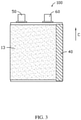
FIG. 3 is a structural diagram of an electrode assembly in an embodiment. -
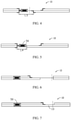
FIG. 4 is an unfolded structural diagram of a first electrode plate in a comparative embodiment. -
FIG. 5 is an unfolded structural diagram of a first electrode plate in an embodiment. -
FIG. 6 is an unfolded structural diagram of a first electrode plate in a comparative embodiment. -
FIG. 7 is an unfolded structural diagram of a first electrode plate in an embodiment. -
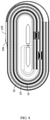
FIG. 8 is a winding structural diagram of an electrode assembly in a comparative embodiment. -
FIG. 9 is a structural diagram of a battery in an embodiment. - The following clearly and fully describes the technical solutions in the embodiments of the application by reference to the accompanying drawings in the embodiments of the application. Apparently, the described embodiments are merely a part of but not all of the embodiments of the application. Based on the embodiments in the application, all other embodiments made by an ordinarily skilled in the art without creative labor fall within the protective scope of the application.
- It needs to be noted that when an element is described to be "fixed to" another element, it can be directly on another element or an intermediate element can exist. When an element is deemed to be "connected to" another element, it can be directly connected to another element or it is possible that an intermediate element exists at the same time. When an element is deemed to be "arranged on" another element, it can be directly arranged on another element or it is possible that an intermediate element exists at the same time. Terms, "perpendicular", "horizontal", "left", "right" and similar expressions, used herein are for the purpose of illustration only.
- Unless otherwise specified, all scientific and technological terms used herein have meanings the same as those generally understood by a skilled in the art of the application. The terms used in the specification of the application herein are merely intended for describing specific embodiments but are not intended to limit this application. The term "or / and" used herein comprises one or any one of and all of combinations of a plurality of relevant listed items.
- An embodiment of the application provides an electrode assembly, which comprises a first electrode plate, a second electrode plate and an separator, wherein the polarity of the second electrode plate is opposite to the polarity of the first electrode plate, the separator is arranged between the first electrode plate and the second electrode plate, and the electrode assembly is formed by winding the first electrode plate, the separator and the second electrode plate. The first electrode plate comprises a first current collector and a first active material layer. The first active material layer is arranged on a surface of the first current collector. A winding terminating end of the first electrode plate is positioned on a side of a winding terminating end of the second electrode plate facing away from the winding core. The first active material layer on the winding terminating end of the first electrode plate covers one surface of the first current collector facing toward the second electrode plate. The electrode assembly further comprises a adhesive member with a thickness of 15 µm - 25 µm. The adhesive member is connected to the winding terminating end of the first electrode plate and covers part of an outer surface of the electrode assembly.
- The design that the electrode assembly does not have the plain aluminum foil at the outermost ring and the combined use of the super-thin adhesive member with a thickness of 15 µm - 25 µm increase the energy density of lithium-ion batteries, also improve the safety used in case of drop, etc., and reduce the aluminum foil consumables of a single electrode assembly.
- The following describes some embodiments of the application in detail. To the extent that no conflict occurs, the following embodiments/implementations and the features in the embodiments/implementations may be combined with each other.
- Referring to
FIG. 1 , in an embodiment of the application, anelectrode assembly 100 comprises afirst electrode plate 10, asecond electrode plate 20 and anseparator 30. Thefirst electrode plate 10 and thesecond electrode plate 20 are opposite in polarity. Theseparator 30 is arranged between thefirst electrode plate 10 and thesecond electrode plate 20. Theelectrode assembly 100 is formed by winding thefirst electrode plate 10, theseparator 30 and thesecond electrode plate 20 around a winding needle, and after the winding process is finished, the winding needle is taken out of theelectrode assembly 100. Theelectrode assembly 100 comprises winding terminating ends, and the winding terminating ends include a winding terminatingend 13 of thefirst electrode plate 10, a winding terminating end of thesecond electrode plate 20 and a winding terminating end of theseparator 30. Thewinding terminating end 31 of theseparator 30 is positioned between the winding terminatingend 13 of thefirst electrode plate 10 and the winding terminating end of thesecond electrode plate 20. The winding terminatingend 13 of thefirst electrode plate 10 is positioned on the outermost layer of theelectrode assembly 100. - The
first electrode plate 10 comprises a first current collector 11 and a firstactive material layer 12. The firstactive material layer 12 is arranged on a surface of the first current collector 11. The winding terminating end of thefirst electrode plate 10 is positioned on an side of the winding terminating end of thesecond electrode plate 20 facing away from a winding core. - In an embodiment of the application, the
first electrode plate 10 is a cathode electrode plate; the first current collector 11 may be an aluminum foil layer; and the firstactive material layer 12 is a cathode active material layer which may be selected from electrochemical active materials that enable reversible intercalation and deintercalation of lithium ions, such as LiCoO2 and LiFePO4. Thesecond electrode plate 20 is an anode electrode plate, which comprises a secondcurrent collector 21 and a secondactive material layer 22. The second current collector may be a copper foil layer. The secondactive material layer 22 may be selected from electrochemical active materials that enable intercalation of lithium ions such as graphite, soft carbon, hard carbon and Li4Ti5O12. - The winding terminating
end 13 of thefirst electrode plate 10 is a structure of the outermost electrode plate of theelectrode assembly 100. The firstactive material layer 12 on the winding terminatingend 13 of thefirst electrode plate 10 covers one surface of the first current collector 11 facing toward thesecond electrode plate 20. The other surface of the first current collector 11 on the winding terminatingend 13 of thefirst electrode plate 10 facing away from thesecond electrode plate 20 is not coated with the firstactive material layer 12. Theelectrode assembly 100 further comprises anadhesive member 40 with a thickness of 15 µm - 25 µm. Theadhesive member 40 is connected to the winding terminating end of thefirst electrode plate 10 and covers part of the outer surface of theelectrode assembly 100. - In an embodiment of the application, the
adhesive member 40 is hot melt adhesive, optionally super-thin hot melt adhesive with a thickness of 15 µm - 25 µm, which may be a rubber binder used in combination with PET. Under certain pressure ( ≤ 3 MPa) and temperature ( ≤ 120° C) conditions, theadhesive member 40 can become viscous. In another word, the hot melting temperature of theadhesive member 40 is smaller than or equal to 120° C, and the hot melting pressure is smaller than or equal to 3 MPa. - Referring to
FIG. 1 again, the outer surface of theelectrode assembly 100 include afirst plane 101, asecond plane 102, afirst arc surface 103 and asecond arc surface 104. Along the thickness direction (a direction pointed at by arrow A inFIG. 1 ) of theelectrode assembly 100, thefirst plane 101 and thesecond plane 102 are arranged opposite to each other. Along the width direction (a direction pointed at by arrow B inFIG. 1 ) of theelectrode assembly 100, thefirst arc surface 103 and thesecond arc surface 104 are arranged opposite to each other, and thefirst arc surface 103 and thesecond arc surface 104 are connected between thefirst plane 101 and thesecond plane 102, respectively. - The winding terminating
end 13 of thefirst electrode plate 10 is approximately positioned at the boundary between thefirst plane 101 and thefirst arc surface 103. Theadhesive member 40 is connected to the winding terminating end of thefirst electrode plate 10 and attached to thefirst arc surface 103, preventing theadhesive member 40 from increasing the thickness of theelectrode assembly 100. In other embodiments, the winding terminating end of the first electrode plate can further be positioned in thefirst plane 101 or thesecond plane 102, and correspondingly, theadhesive member 40 can further be attached to thefirst plane 101 or thesecond plane 102. - Further, to prevent burrs generated by lithium separation at an end portion of the
second electrode plate 20 from resulting in a short circuit when the burrs penetrate through theseparator 30 and connect thefirst electrode plate 10, the winding terminating end of thesecond electrode plate 20 extends out of the winding terminatingend 13 of thefirst electrode plate 10 along the winding direction of the electrode plate. The extension length L1 is greater than or equal to 2 mm. The winding terminatingend 31 of theseparator 30 extends out of the winding terminating end of thesecond electrode plate 20 and is attached to the inner surface of theadhesive member 40. The length L2 by which the winding terminatingend 31 of theseparator 30 extends out of thesecond electrode plate 20 is greater than or equal to 4 mm. The winding terminating end of thesecond electrode plate 20 is covered by the winding terminatingend 31 of the separator so as to protect and insulate the winding terminating end of thesecond electrode plate 20. - Referring to
FIG. 1 andFIG. 3 , theelectrode assembly 100 further comprises afirst tab 50 and asecond tab 60, wherein thefirst tab 50 is connected to thefirst electrode plate 10, and thesecond tab 60 is connected to thesecond electrode plate 20. Along the thickness direction of theelectrode assembly 100, the projections of thefirst tab 50 and thesecond tab 60 are not overlapped. Along the length direction (a direction pointed at by arrow C inFIG. 3 ) of theelectrode assembly 100, thefirst tab 50 and thesecond tab 60 extend out of the same end of theelectrode assembly 100. In other embodiments, thefirst tab 50 and thesecond tab 60 can extend out of different ends of theelectrode assembly 100. The application is not limited to such way. - Further, a winding starting end of the
first electrode plate 10 is provided with a firstplain foil area 14; a winding starting end of thesecond electrode plate 20 is provided with a secondplain foil area 23; thefirst tab 50 is arranged in the firstplain foil area 14; and thesecond tab 60 is arranged in the secondplain foil area 23. Theelectrode assembly 100 comprises a first insulatingmember 70. The first insulatingmember 70 is arranged in the firstplain foil area 14 and covers thefirst tab 50, preventing the burrs on thefirst tab 50 from resulting in a short circuit when the burrs penetrate through theseparator 30 and contact thesecond electrode plate 20. In an optional embodiment, the first insulatingmember 70 can be an insulating tape, which extends from thefirst tab 50 to a starting end of the firstactive material layer 12 and almost covers the entire firstplain foil area 14, such that the firstplain foil area 14 is well protected against incidents such as breakage and the short circuit. - In an optional embodiment, the second
plain foil area 23 extends out of the firstplain foil area 14, and thesecond tab 60 is arranged in an area of the secondplain foil area 23, wherein the area extends out of the firstplain foil area 14. Even if the burrs on thesecond tab 60 penetrate through theseparator 30, thesecond tab 60 contacts thesecond electrode plate 20 instead of contacting thefirst electrode plate 10 so as to avoid the short circuit. Theelectrode assembly 100 further comprises a second insulatingmember 80. The second insulatingmember 80 covers an end portion of the firstplain foil area 14, preventing the burrs at the end portion of the firstplain foil area 14 from penetrating through theseparator 30 and contacting thesecond electrode plate 20. - Referring to
FIG. 2 , in one of the embodiments of the application, thefirst tab 50 is arranged in an area coated with the firstactive material layer 12 on the first current collector 11, and thesecond tab 60 is arranged in an area coated with the secondactive material layer 22 on the secondcurrent collector 21. The first insulatingmember 70 is arranged at both thefirst tab 50 and thesecond tab 60 to avoid the short-circuiting problem. To connect thefirst tab 50 to the first current collector 11, it needs to remove part of the firstactive material layer 12 first, such that part of the first current collector 11 is exposed out of the firstactive material layer 12, and then thefirst tab 50 needs to be welded on the exposed part of the first current collector 11. Thesecond tab 60 is connected to the secondcurrent collector 21 by the similar way, which is not described repeatedly here. - In other embodiments, the
first tab 50 and thesecond tab 60 can further be separately arranged in either the plain foil area at the winding core of theelectrode assembly 100 or other positions of the electrode plate. The application is not limited to such way. - Referring to
FIG. 4 and FIG. 5 , the position shown by the dotted line in the figures is the cut position of two adjacentfirst electrode plates 10 during manufacturing. When thefirst tab 50 is arranged in the firstplain foil area 14, since the electrode assembly in the comparative embodiment is provided with a section of plain aluminum foil at the outermost ring, and in the comparative embodiment as shown inFIG. 4 the length L3 of the plain aluminum foil area is apparently greater than the length L4 of the plain aluminum foil area in the embodiment of the application as shown inFIG. 5 , the length L4 of the plain aluminum foil area in the embodiment of the application only needs to meet the parameter requirement of the winding starting end of theelectrode assembly 100, which saves the aluminum foil consumables, removes the plain aluminum foil at the outermost ring, enhances the energy density and improves the safety of theelectrode assembly 100 used in occasions such as drop. - Referring to
FIG. 6 and FIG. 7 , when thefirst tab 50 is arranged in the area coated with the firstactive material layer 12 on the first current collector 11, the electrode assembly in the comparative embodiment is provided with a section of plain aluminum foil at the outermost ring, in the comparative embodiment as shown inFIG. 6 , a section of single-coated area and a section of plain aluminum foil exist between two adjacentfirst electrode plates 10 and the single-coated area is the winding terminatingend 13 of thefirst electrode plate 10, while in the embodiment of the application as shown inFIG. 7 , the plain aluminum foil between two adjacentfirst electrode plates 10 is removed and there is only a section of single-coated area (the winding terminatingend 13 of the first electrode plate 10), such that the firstactive material layer 12 on the lower surface of the first current collector 11 can be continuous, thereby simplifying the manufacturing process of thefirst electrode plate 10 and improving the production efficiency. - Referring to
FIG. 8 , in a comparative embodiment, part of plain aluminum foil 105 (without the active material coating on both sides) exists in the outer tail of the electrode assembly, and the tail plain aluminum foil and the coating edge at the tail are attached with one layer of insulatingtape 106. Theplain aluminum foil 105 and the insulatingtape 106 are both positioned in thesecond plane 102 of the electrode assembly. - In conjunction with the above-mentioned embodiments of the application and by reference to the above-mentioned comparative embodiments, the increase ratios of the energy densities of
electrode assemblies 100 obtained using corresponding embodiments were measured, which can be seen in the table below. - When the thickness of the aluminum foil is 10 µm:
Group of the electrode assembly thickness Thickness in the comparative embodiment µm Thickness in the embodiment µm Increase ratio of the energy density 1 3000 2990 0.33% 2 3500 3490 0.29% 3 4000 3990 0.25% 4 4500 4490 0.22% 5 5000 4990 0.20% 6 5500 5490 0.18% 7 6000 5990 0.17% 8 6500 6490 0.15% - When the thickness of the aluminum foil is 12 µm:
Group of the electrode assembly thickness Thickness in the comparative embodiment µm Thickness in the embodiment µm Increase ratio of the energy density 1 3000 2988 0.40% 2 3500 3488 0.34% 3 4000 3988 0.30% 4 4500 4488 0.27% 5 5000 4988 0.24% 6 5500 5488 0.22% 7 6000 5988 0.20% 8 6500 6488 0.18% - The drop test data of the electrode assembly in the comparative embodiment and in the embodiment of the application can be seen in the table below.
- Basic parameters of the electrode assembly in the embodiment and the comparative embodiment in the first test group are as follows:
- Capacity of the battery core: 3200mAh; chemical system: 4.35V; S\A overhang: 2.0mm. S: Separator; A: Anode; overhang: 2.0 mm which indicates that the width of the separator is 2 mm greater than that of the anode electrode plate. The anode electrode plate is the first electrode plate.
- Test data of the first group:
Group Pass number of drop Pass ratio Embodiment 4/10 pass 40% Comparative embodiment 0/10 pass 0% Group unbroken package Overturned separator Smoking/fire Pass ratio Embodiment 0/20 0/20 0/20 100% Comparative embodiment 1/20 2/20 0/20 85% - Basic parameters of the electrode assemblies in the embodiment and the comparative embodiment in the second test group are as follows:
- Capacity of the battery core: 4000mAh; chemical system: 4.35V; S\A overhang: 2.0mm.
- Test data of the second group:
Group Unbroken package Overturned separator Smoking/fire Pass ratio Embodiment 0/20 1/20 0/20 95% Comparative embodiment 1/20 3/20 0/20 80% - In conjunction with
FIGS. 4-8 and data in the table above, in the embodiment of the application, comparing with the comparative embodiment, the design that theelectrode assembly 100 is not provided with the plain aluminum foil at the outermost ring, and that theadhesive member 40 connects the winding terminating end of thefirst electrode plate 10 and part of the outer surface of theelectrode assembly 100, reduces the thickness of theelectrode assembly 100 and enhances the energy density and drop safety at the same time. - Referring to
FIG. 9 , an embodiment of the application further provides abattery 200, which comprises apackage 201 and theelectrode assembly 100 in the foregoing embodiments, wherein theelectrode assembly 100 is accommodated in thepackage 201, and the tabs of theelectrode assembly 100 extend out of thepackage 201. - The foregoing embodiments are merely used to describe the technical solution of the application, and not to limit the application. Despite of detailed description of the application by reference to the foregoing preferable embodiments, an ordinarily skilled in the art should understand that, various modifications and equivalent substitutions may be made to the technical solutions of the application, and all such modifications and equivalent substitutions fall within the technical conception and scope of the technical solution of the application.
| |
100 |
| |
101 |
| |
102 |
| |
103 |
| |
104 |
| |
105 |
| |
106 |
| |
10 |
| First current collector | 11 |
| First |
12 |
| Winding terminating |
13 |
| First |
14 |
| |
20 |
| Second |
21 |
| Second |
22 |
| Second |
23 |
| |
30 |
| Winding terminating |
31 |
| |
40 |
| |
50 |
| |
60 |
| First |
70 |
| Second |
80 |
| |
200 |
| |
201 |
Claims (10)
- An electrode assembly, comprising:a first electrode plate;a second electrode plate, with a polarity opposite to the polarity of the first electrode plate;a separator arranged between the first electrode plate and the second electrode plate, the electrode assembly being formed by winding the first electrode plate, the separator and the second electrode plate;characterized in that, the first electrode plate comprises a first current collector and a first active material layer, the first active material layer is arranged on a surface of the first current collector, and a winding terminating end of the first electrode plate is positioned on an outer side of a winding terminating end of the second electrode plate facing away from a winding core;the first active material layer on the winding terminating end of the first electrode plate covers one surface of the first current collector facing toward the second electrode plate; and the electrode assembly further comprises a adhesive member with a thickness of 15 µm - 25 µm, the adhesive member being connected to the winding terminating end of the first electrode plate and covering part of the outer surface of the electrode assembly to fix the winding terminating end of the first electrode plate.
- The electrode assembly according to claim 1, characterized in that, the adhesive member is hot melt adhesive, and is adhered to the winding terminating end of the first electrode plate and the outer surface of the electrode assembly.
- The electrode assembly according to claim 2, characterized in that, the hot melting temperature of the adhesive member is less than or equal to 120° C, and the hot melting pressure is less than or equal to 3 MPa.
- The electrode assembly according to claim 1, characterized in that, the winding terminating end of the second electrode plate extends out of the winding terminating end of the first electrode plate along a winding direction, and the extension length is greater than or equal to 2mm.
- The electrode assembly according to claim 4, characterized in that, a winding terminating end of the separator extends out of the winding terminating end of the second electrode plate along the winding direction, and is attached to the inner surface of the adhesive member.
- The electrode assembly according to claim 1, characterized in that, the electrode assembly further comprises a first tab and a second tab, the first tab is connected to the first electrode plate, and the second tab is connected to the second electrode plate.
- The electrode assembly according to claim 6, characterized in that, a winding starting end of the first electrode plate is provided with a first plain foil area, a winding starting end of the second electrode plate is provided with a second plain foil area, the first tab is arranged in the first plain foil area, and the second tab is arranged in the second plain foil area.
- The electrode assembly according to claim 7, characterized in that, the electrode assembly comprises a first insulating member, the first insulating member being arranged in the first plain foil area and covering the first tab.
- The electrode assembly according to claim 7, characterized in that, the second plain foil area extends out of the first plain foil area, the electrode assembly further comprises a second insulating member, and the second insulating member covers an end portion of the first plain foil area.
- A battery, characterized in that, the battery comprises an electrode assembly according to any one of claims 1 to 9 and a package, the electrode assembly is accommodated in the package, and the tabs of the electrode assembly extend out of the package.
Applications Claiming Priority (1)
| Application Number | Priority Date | Filing Date | Title |
|---|---|---|---|
| PCT/CN2020/091386 WO2021232314A1 (en) | 2020-05-20 | 2020-05-20 | Electrode assembly and battery |
Publications (2)
| Publication Number | Publication Date |
|---|---|
| EP3940855A1 true EP3940855A1 (en) | 2022-01-19 |
| EP3940855A4 EP3940855A4 (en) | 2022-04-20 |
Family
ID=75368501
Family Applications (1)
| Application Number | Title | Priority Date | Filing Date |
|---|---|---|---|
| EP20864327.0A Pending EP3940855A4 (en) | 2020-05-20 | 2020-05-20 | Electrode assembly and battery |
Country Status (6)
| Country | Link |
|---|---|
| US (1) | US20210367271A1 (en) |
| EP (1) | EP3940855A4 (en) |
| JP (1) | JP7359848B2 (en) |
| KR (1) | KR102653550B1 (en) |
| CN (1) | CN112655112B (en) |
| WO (1) | WO2021232314A1 (en) |
Cited By (1)
| Publication number | Priority date | Publication date | Assignee | Title |
|---|---|---|---|---|
| EP4160780A4 (en) * | 2020-12-10 | 2024-10-09 | Zhuhai CosMX Battery Co., Ltd. | LITHIUM BATTERY |
Families Citing this family (9)
| Publication number | Priority date | Publication date | Assignee | Title |
|---|---|---|---|---|
| CN113013377A (en) * | 2021-04-20 | 2021-06-22 | 珠海冠宇电池股份有限公司 | Battery with a battery cell |
| CN114586231B (en) * | 2021-06-29 | 2024-02-23 | 宁德新能源科技有限公司 | Batteries and electrical devices having said batteries |
| CN216213939U (en) | 2021-11-01 | 2022-04-05 | 宁德新能源科技有限公司 | Battery cell, battery and electronic equipment |
| CN114069025A (en) * | 2021-11-17 | 2022-02-18 | 珠海冠宇电池股份有限公司 | Roll up core structure and battery |
| CN116666726A (en) * | 2022-02-21 | 2023-08-29 | 宁德时代新能源科技股份有限公司 | Battery monomer, battery, electric equipment and manufacturing method of battery monomer |
| CN119585911A (en) * | 2022-08-19 | 2025-03-07 | 株式会社Lg新能源 | Electrode assembly and secondary battery including the same |
| CN121548879A (en) * | 2023-07-31 | 2026-02-17 | 松下新能源株式会社 | Non-aqueous electrolyte secondary battery |
| CN117832646A (en) * | 2024-01-12 | 2024-04-05 | 宁德新能源科技有限公司 | Cells and secondary batteries |
| WO2026065478A1 (en) * | 2024-09-30 | 2026-04-02 | 宁德新能源科技有限公司 | Secondary battery and electronic device |
Family Cites Families (23)
| Publication number | Priority date | Publication date | Assignee | Title |
|---|---|---|---|---|
| JP2548464B2 (en) * | 1991-07-01 | 1996-10-30 | 松下電器産業株式会社 | Non-aqueous electrolyte battery |
| JP3444302B2 (en) * | 1992-02-24 | 2003-09-08 | ソニー株式会社 | Non-aqueous electrolyte secondary battery |
| JP2002343419A (en) | 2001-05-18 | 2002-11-29 | Yuasa Corp | Sealed battery |
| JP4815845B2 (en) | 2005-04-04 | 2011-11-16 | ソニー株式会社 | Polymer battery |
| CN101150183A (en) * | 2006-09-19 | 2008-03-26 | 深圳市比克电池有限公司 | A coiling lithium secondary battery |
| JP4586820B2 (en) * | 2007-05-07 | 2010-11-24 | ソニー株式会社 | Winding type non-aqueous electrolyte secondary battery |
| JP2010055906A (en) | 2008-08-28 | 2010-03-11 | Sanyo Electric Co Ltd | Nonaqueous electrolyte secondary battery |
| JP5283544B2 (en) * | 2009-03-10 | 2013-09-04 | 三洋電機株式会社 | Nonaqueous electrolyte secondary battery |
| KR101118259B1 (en) * | 2009-06-05 | 2012-03-20 | 삼성에스디아이 주식회사 | Electrode assembly and secondary battery using the same |
| JP5783425B2 (en) | 2012-08-08 | 2015-09-24 | トヨタ自動車株式会社 | Method for producing non-aqueous electrolyte secondary battery |
| US10530012B2 (en) * | 2014-11-18 | 2020-01-07 | Zeon Corporation | Method for producing an electrochemical device |
| CN107112494B (en) * | 2015-06-09 | 2020-11-06 | 株式会社村田制作所 | Battery, battery pack, electronic device, electric vehicle, power storage device, and power system |
| JP6202347B2 (en) * | 2015-06-25 | 2017-09-27 | トヨタ自動車株式会社 | Non-aqueous electrolyte secondary battery |
| KR102278442B1 (en) * | 2016-09-21 | 2021-07-16 | 삼성에스디아이 주식회사 | Rechargeable lithium battery |
| CN106410265B (en) * | 2016-10-31 | 2019-02-26 | 深圳市比克动力电池有限公司 | A cylindrical lithium-ion battery |
| CN206697567U (en) * | 2017-03-31 | 2017-12-01 | 宁德新能源科技有限公司 | Takeup type battery core |
| CN109755461A (en) | 2017-11-07 | 2019-05-14 | 宁德新能源科技有限公司 | Wind battery core |
| JP7187481B2 (en) * | 2017-12-08 | 2022-12-12 | 三洋電機株式会社 | Non-aqueous electrolyte secondary battery |
| WO2019163392A1 (en) * | 2018-02-22 | 2019-08-29 | 三洋電機株式会社 | Non-aqueous electrolyte secondary battery |
| KR102519604B1 (en) | 2018-03-06 | 2023-04-10 | 닝더 엠프렉스 테크놀로지 리미티드 | winding cell |
| CN110808377B (en) * | 2018-08-06 | 2021-04-27 | 宁德新能源科技有限公司 | Cells, Batteries and Electronic Devices |
| CN109461879A (en) * | 2018-10-31 | 2019-03-12 | 合肥国轩高科动力能源有限公司 | A kind of single batch coating type lithium ion battery and preparation method thereof |
| CN109473729B (en) * | 2018-11-05 | 2020-11-13 | 宁德新能源科技有限公司 | Electrochemical device |
-
2020
- 2020-05-20 EP EP20864327.0A patent/EP3940855A4/en active Pending
- 2020-05-20 KR KR1020217016426A patent/KR102653550B1/en active Active
- 2020-05-20 WO PCT/CN2020/091386 patent/WO2021232314A1/en not_active Ceased
- 2020-05-20 JP JP2021516951A patent/JP7359848B2/en active Active
- 2020-05-20 CN CN202080004953.9A patent/CN112655112B/en active Active
-
2021
- 2021-03-31 US US17/219,702 patent/US20210367271A1/en active Pending
Cited By (1)
| Publication number | Priority date | Publication date | Assignee | Title |
|---|---|---|---|---|
| EP4160780A4 (en) * | 2020-12-10 | 2024-10-09 | Zhuhai CosMX Battery Co., Ltd. | LITHIUM BATTERY |
Also Published As
| Publication number | Publication date |
|---|---|
| EP3940855A4 (en) | 2022-04-20 |
| CN112655112B (en) | 2022-10-04 |
| US20210367271A1 (en) | 2021-11-25 |
| JP2022537227A (en) | 2022-08-25 |
| CN112655112A (en) | 2021-04-13 |
| WO2021232314A1 (en) | 2021-11-25 |
| KR20210072823A (en) | 2021-06-17 |
| JP7359848B2 (en) | 2023-10-11 |
| KR102653550B1 (en) | 2024-04-03 |
Similar Documents
| Publication | Publication Date | Title |
|---|---|---|
| US20210367271A1 (en) | Electrode assembly and battery | |
| EP2610954B1 (en) | Improved jelly-roll structure, and secondary battery having same | |
| JP4373073B2 (en) | Battery unit and secondary battery using the same | |
| EP2048736B1 (en) | Lithium secondary battery | |
| JP6505859B2 (en) | Nonaqueous electrolyte secondary battery | |
| JP4418243B2 (en) | Jelly roll type electrode assembly and secondary battery employing the same | |
| US20250349907A1 (en) | Electrode assembly and battery | |
| KR20240004848A (en) | Battery electrode plate, battery and battery electrode plate manufacturing method | |
| JP2004119383A (en) | Electrode assembly of lithium ion battery and lithium ion battery using the same | |
| CN115458879A (en) | Battery cell and battery cell manufacturing method | |
| US10693192B2 (en) | Wound-type cell | |
| CN117832646A (en) | Cells and secondary batteries | |
| EP4697478A1 (en) | Battery cell, battery and electric device | |
| KR20220048859A (en) | Secondary battery | |
| WO2024077652A1 (en) | Cell pack and power battery | |
| JP4639818B2 (en) | Battery pack | |
| KR102789781B1 (en) | Pouch-type secondary battery | |
| CN224248672U (en) | Battery cell, lithium ion battery and electric equipment | |
| CN220984800U (en) | Battery winding core protection structure, battery and electric equipment | |
| EP4383441A1 (en) | Electrodes configuration in a battery | |
| KR20030081640A (en) | Jelly-roll type battery unit and the secondary battery applying the same | |
| KR20250036106A (en) | Pouch-type secondary battery | |
| CN120109453A (en) | Secondary batteries and electrical equipment | |
| JP2008097964A (en) | Non-aqueous electrolyte battery | |
| KR100635716B1 (en) | Secondary battery |
Legal Events
| Date | Code | Title | Description |
|---|---|---|---|
| STAA | Information on the status of an ep patent application or granted ep patent |
Free format text: STATUS: UNKNOWN |
|
| STAA | Information on the status of an ep patent application or granted ep patent |
Free format text: STATUS: THE INTERNATIONAL PUBLICATION HAS BEEN MADE |
|
| PUAI | Public reference made under article 153(3) epc to a published international application that has entered the european phase |
Free format text: ORIGINAL CODE: 0009012 |
|
| STAA | Information on the status of an ep patent application or granted ep patent |
Free format text: STATUS: REQUEST FOR EXAMINATION WAS MADE |
|
| 17P | Request for examination filed |
Effective date: 20210326 |
|
| AK | Designated contracting states |
Kind code of ref document: A1 Designated state(s): AL AT BE BG CH CY CZ DE DK EE ES FI FR GB GR HR HU IE IS IT LI LT LU LV MC MK MT NL NO PL PT RO RS SE SI SK SM TR |
|
| A4 | Supplementary search report drawn up and despatched |
Effective date: 20220318 |
|
| RIC1 | Information provided on ipc code assigned before grant |
Ipc: H01M 10/0587 20100101AFI20220314BHEP |
|
| DAV | Request for validation of the european patent (deleted) | ||
| DAX | Request for extension of the european patent (deleted) | ||
| STAA | Information on the status of an ep patent application or granted ep patent |
Free format text: STATUS: EXAMINATION IS IN PROGRESS |
|
| 17Q | First examination report despatched |
Effective date: 20240321 |