EP3940673B1 - Systeme und verfahren zur darstellung von umgebungsinformationen über eine missionszeitachse - Google Patents
Systeme und verfahren zur darstellung von umgebungsinformationen über eine missionszeitachse Download PDFInfo
- Publication number
- EP3940673B1 EP3940673B1 EP21184121.8A EP21184121A EP3940673B1 EP 3940673 B1 EP3940673 B1 EP 3940673B1 EP 21184121 A EP21184121 A EP 21184121A EP 3940673 B1 EP3940673 B1 EP 3940673B1
- Authority
- EP
- European Patent Office
- Prior art keywords
- weather
- flight segment
- event indicator
- impact
- beginning
- Prior art date
- Legal status (The legal status is an assumption and is not a legal conclusion. Google has not performed a legal analysis and makes no representation as to the accuracy of the status listed.)
- Active
Links
Images


Classifications
-
- G—PHYSICS
- G08—SIGNALLING
- G08G—TRAFFIC CONTROL SYSTEMS
- G08G5/00—Traffic control systems for aircraft
- G08G5/70—Arrangements for monitoring traffic-related situations or conditions
- G08G5/76—Arrangements for monitoring traffic-related situations or conditions for monitoring atmospheric conditions
-
- G—PHYSICS
- G08—SIGNALLING
- G08G—TRAFFIC CONTROL SYSTEMS
- G08G5/00—Traffic control systems for aircraft
- G08G5/20—Arrangements for acquiring, generating, sharing or displaying traffic information
- G08G5/21—Arrangements for acquiring, generating, sharing or displaying traffic information located onboard the aircraft
-
- G—PHYSICS
- G08—SIGNALLING
- G08G—TRAFFIC CONTROL SYSTEMS
- G08G5/00—Traffic control systems for aircraft
- G08G5/50—Navigation or guidance aids
-
- G—PHYSICS
- G08—SIGNALLING
- G08G—TRAFFIC CONTROL SYSTEMS
- G08G5/00—Traffic control systems for aircraft
- G08G5/50—Navigation or guidance aids
- G08G5/53—Navigation or guidance aids for cruising
-
- G—PHYSICS
- G08—SIGNALLING
- G08G—TRAFFIC CONTROL SYSTEMS
- G08G5/00—Traffic control systems for aircraft
- G08G5/50—Navigation or guidance aids
- G08G5/55—Navigation or guidance aids for a single aircraft
Definitions
- the following disclosure relates generally to aircraft display systems, and, more particularly, to systems and methods for presenting environment information on a mission timeline on an aircraft display system.
- An integral part of some available aircraft display systems is an interactive map application that offers a means of navigation and provides a possibility to retrieve and review multiple additional information sources, including environment data such as weather, airspace restrictions and notices to airmen (NOTAMs).
- environment data such as weather, airspace restrictions and notices to airmen (NOTAMs).
- NOTAMs airspace restrictions and notices to airmen
- These available aircraft display systems may present data in the form of one or more interactive map layers that can be overlaid on top of each other.
- a trend in aircraft display systems is to offer a mission-oriented approach, which provides a timeline and places graphic symbols along the timeline to indicate required activities and situations requiring attention.
- Some mission timeline solutions may utilize a graphic symbol alongside the mission timeline to indicate a weather event on the planned flight plan (FP).
- FP planned flight plan
- a technical problem is presented in that a pilot or crew may need to know, not only that there is a thunderstorm ahead on the FP, but its significance (e.g., level of severity and additional details that may impact the aircraft).
- a flight plan (FP) display system on an aircraft for automating processes of receiving, prioritizing, and grouping weather data into a weather event with an associated extent for presentation on a displayed mission timeline
- the system including a controller circuit with a processor configured by programming instructions on non-transient computer readable media, the controller circuit configured to: receive weather data from at least one weather source; reference aircraft state data and aircraft system status data; and identify a weather phenomenon that impacts the FP by processing the weather data with the aircraft state data, aircraft system status data, and the FP; create an information structure for the weather phenomenon, the information structure including a type, a subtype, a severity, a start of impact and an end of impact; present a weather event indicator overlaid on the mission timeline to depict the weather phenomenon; present an alphanumeric notice of the weather event next to the weather event indicator; and depict an extent of the weather event with a beginning of the weather event indicator and an end of the weather event indicator; wherein: the beginning of the weather event indicator is aligned with a beginning of a flight segment
- a method for automating processes of receiving, prioritizing, and grouping weather data into a weather event with an associated extent for presentation on a displayed mission timeline in an aircraft having a flight plan (FP) including: receiving, by a controller circuit with a processor configured by programming instructions, weather data from at least one weather source; referencing, by the controller circuit, aircraft state data and aircraft system status data; and identifying, by the controller circuit, a weather phenomenon that impacts the FP by processing the weather data with the aircraft state data, the aircraft system status data, and the FP; creating an information structure for the weather phenomenon, the information structure including a type, a subtype, a severity, a start of impact and an end of impact; presenting a weather event indicator overlaid on the mission timeline to depict the weather phenomenon; presenting an alphanumeric notice of the weather event next to the weather event indicator; and depicting an extent of the weather event with a beginning of the weather event indicator and an end of the weather event indicator; wherein: the beginning of the weather event indicator is align
- a mission timeline display system displaying a mission timeline for a flight plan (FP) of an aircraft.
- the mission timeline display system including: a significant environment processing module configured to: communicate with aircraft ownship data sources and external data sources using a communications circuit; and identify a weather phenomenon that impacts the FP; a creation of information structure module configured to operate on the weather phenomenon and create an information structure therefrom; and a display processing module configured to operate on the information structure to generate and display on the mission timeline display: a weather event indicator, overlaid on the mission timeline to depict the weather phenomenon; and an alphanumeric notice of the weather event, next to the weather event indicator; and wherein the weather event has an extent indicated with a beginning of the weather event indicator and an end of the weather event indicator; wherein: the beginning of the weather event indicator is aligned with a beginning of a flight segment when the start of impact occurs at or within a first prescribed snap-to start percent of the flight segment; the beginning of the weather event indicator is placed after the beginning of the flight segment when (i) the start of impact occurs after
- a mission-oriented approach in aircraft display systems generally provides a mission timeline and places graphic symbols along the timeline at locations that indicate when required activities should be performed and when situations requiring attention may occur.
- Some mission timeline solutions may place a graphic symbol alongside the mission timeline of the planned flight plan (FP) to indicate a weather event.
- FP planned flight plan
- a technical problem is presented in that a pilot or crew may need to know more than simply that there is a weather event ahead on the FP, such as, its significance (e.g., level of severity, extent/duration, and potential impact to the aircraft).
- the present disclosure provides a technical solution to the limitations of available solutions, in the form of systems and methods for providing environment information on a mission timeline.
- the provided systems and methods automate the processes of receiving, prioritizing, and grouping weather data into a weather event and event extent with an associated duration for presentation on a displayed mission timeline on an aircraft flight plan (FP) display system.
- FP aircraft flight plan
- the provided systems and methods generate a weather event indicator that, by its size and placement on the mission timeline, visually communicates a start, and end, and an extent/duration of the weather event.
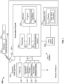
- FIG. 1 is a block diagram of a system 102 for automating the process of receiving, prioritizing, and grouping weather data into a weather event with an event extent an associated duration for presentation on a displayed mission timeline (shortened hereinafter to "system 102 "), as illustrated in accordance with an exemplary and non-limiting embodiment of the present disclosure.
- the system 102 may be utilized onboard a mobile platform 100 to provide enhanced weather alerting, as described herein.
- the mobile platform is an aircraft 100, which carries or is equipped with the system 102. As schematically depicted in FIG.
- system 102 may include the following components or subsystems, each of which may assume the form of a single device, system on chip (SOC), or multiple interconnected devices: a controller circuit 104 operationally coupled to: at least one display unit 110 ; computer-readable storage media or memory 132 ; a user input interface 114 , and ownship data sources 106 including one or more flight management system computers (FMS computers 116 ), aircraft system status sensors and geospatial sensors.
- the system 102 may be separate from or integrated within: a FMS computer 116 and/or a flight control system (FCS).
- FCS flight control system
- the system 102 may also contain a communications circuit 140 and an antenna 142 , which may wirelessly transmit data to and receive real-time data and signals from various external sources 144 , including, each of: weather source(s) 146 , air traffic control (ATC 148 ), and the like.
- various external sources 144 including, each of: weather source(s) 146 , air traffic control (ATC 148 ), and the like.
- FIG. 1 Although schematically illustrated in FIG. 1 as a single unit, the individual elements and components of the system 102 can be implemented in a distributed manner utilizing any practical number of physically distinct and operatively interconnected pieces of hardware or equipment. When the system 102 is utilized as described herein, the various components of the system 102 will typically all be located onboard the Aircraft 100.
- controller circuit broadly encompasses those components utilized to carry-out or otherwise perform the processes and/or support the processing functionalities of the system 102. Accordingly, controller circuit 104 can encompass or may be associated with a programmable logic array, and an application specific integrated circuit or other similar firmware, as well as any number of individual processors, flight control computers, navigational equipment pieces, computer-readable memories (including or in addition to memory 132 ), power supplies, storage devices, interface cards, and other standardized components.
- controller circuit 104 embodies one or more processors operationally coupled to data storage having stored therein at least one firmware or software program (generally, a program product or program of computer-readable instructions that embody an algorithm) for carrying-out the various process tasks, calculations, and control/display functions described herein.
- the controller circuit 104 may execute an algorithm for automating the process of receiving, prioritizing, and grouping weather data into a weather event with an associated duration for presentation on a displayed mission timeline for an aircraft 100 , to thereby perform the various process steps, tasks, calculations, and control/display functions described herein.
- the algorithm is embodied as at least one firmware or software program (e.g., program 134 ).
- Communications circuit 140 is configured to provide a real-time bidirectional wired and/or wireless data exchange for the processor 130 with the ownship data sources 106 , the user input device 108 , the display unit 110 , and the external sources 144 to support operation of the system 102 in embodiments.
- the communications circuit 140 may include a public or private network implemented in accordance with Transmission Control Protocol/Internet Protocol architectures and/or other conventional protocol standards. Encryption and mutual authentication techniques may be applied, as appropriate, to ensure data security.
- the communications circuit 140 is integrated within the controller circuit 104 as shown in FIG. 1 , and in other embodiments, the communications circuit 140 is external to the controller circuit 104.
- a variety of ownship data sources 106 may be operationally coupled to the controller circuit 104.
- one or more flight management system (FMS) 116 computers may bidirectionally communicate with the controller circuit 104.
- the FMS 116 may provide a flight plan (FP).
- Flight parameter sensors and geospatial sensors 118 supply various types of aircraft state data or measurements to controller circuit 104 during aircraft flight.
- the aircraft state data supplied by the geospatial sensors 118 include, without limitation, one or more of: inertial reference system measurements providing a location, Flight Path Angle (FPA) measurements, airspeed data, groundspeed data (including groundspeed direction), vertical speed data, vertical acceleration data, altitude data, attitude data including pitch data and roll measurements, yaw data, heading information, sensed atmospheric conditions data (including wind speed and direction data), flight path data, flight track data, radar altitude data, and geometric altitude data.
- Aircraft system status sensors 120 may provide aircraft system status data, such as, engine status, fuel status, a current aircraft configuration (e.g., spoiler/speed brake configuration), and the like.
- On-board weather radar sensors 122 can provide weather data associated with the immediate surroundings of the aircraft 100.
- the FMS 116 and onboard sensor systems provide data and information on a communication bus 125 and the controller circuit 104 receives the sensor data and information therefrom.
- External sources 144 may communicate with the controller circuit 104, for example, wirelessly, and via antenna 142.
- External sources include external weather sources 146, air traffic control (ATC) 148, and traffic data sources.
- external weather sources 146 may be any combination of one or more of meteorological weather information, such as, uplink weather (XM/SXM, GDC/GoDirect Weather), NOTAM/D-NOTAM, TAF, D-ATIS.
- a display unit 110 can include any number and type of image generating devices on which one or more avionic displays 112 may be produced.
- display unit 110 may be affixed to the static structure of the Aircraft cockpit as, for example, a Head Down Display (HDD) or Head Up Display (HUD) unit.
- display unit 110 may assume the form of a movable display device (e.g., a pilot-worn display device) or a portable display device, such as an Electronic Flight Bag (EFB), a laptop, or a tablet computer carried into the Aircraft cockpit by a pilot.
- a movable display device e.g., a pilot-worn display device
- EFB Electronic Flight Bag
- At least one avionic display 112 is generated on display unit 110 during operation of the system 102; the term "avionic display” defined as synonymous with the term “aircraft-related display” and “cockpit display” and encompasses displays generated in textual, graphical, cartographical, and other formats.
- the system 102 can generate various types of lateral and vertical avionic displays on which map views and symbology, text annunciations, and other graphics pertaining to flight planning are presented for a pilotto view.
- the display unit 110 is configured to continuously render at least a lateral display showing the Aircraft 100 at its current location within the map data.
- the avionic display 112 generated and controlled by the system 102 can include a user input interface 114, including graphical user interface (GUI) objects and alphanumerical displays of the type commonly presented on the screens of MCDUs, as well as Control Display Units (CDUs) generally.
- GUI graphical user interface
- CDU Control Display Unit
- embodiments of avionic displays 112 include one or more two dimensional (2D) avionic displays, such as a horizontal (i.e., lateral) navigation display or vertical navigation display; and/or on one or more three dimensional (3D) avionic displays, such as a Primary Flight Display (PFD) or an exocentric 3D avionic display.
- 2D two dimensional
- 3D Three dimensional
- a human-machine interface is implemented as an integration of a user input interface 114 and a display unit 110.
- the display unit 110 is a touch screen display.
- the human-machine interface also includes a separate user input device 108 (such as a keyboard, cursor control device, voice input device, or the like), generally operationally coupled to the display unit 110.
- the controller circuit 104 may command and control a touch screen display unit 110 to generate a variety of graphical user interface (GUI) objects or elements described herein, including, for example, buttons, sliders, and the like, which are used to prompt a user to interact with the human-machine interface to provide user input; and for the controller circuit 104 to activate respective functions and provide user feedback, responsive to received user input at the GUI element.
- GUI graphical user interface
- the controller circuit 104 may include a processor 130 and a memory 132.
- Memory 132 is a data storage that can encompass any number and type of storage media suitable for storing computer-readable code or instructions, such as the aforementioned software program 134 , as well as other data generally supporting the operation of the system 102.
- Memory 132 may also store one or more preprogrammed variables 136 and thresholds, for use by an algorithm embodied in the software program 134. Examples of preprogrammed variables 136 include the "snap-to start" and "snap-to end” percentages described below.
- One or more database(s) 138 are another form of storage media that the system 102 may employ; they may be integrated with memory 132 or separate from it.
- aircraft-specific parameters and information for aircraft 100 may be stored in the memory 132 or in a database 138 and referenced by the program 134.
- aircraft-specific information includes an aircraft weight and dimensions, performance capabilities, configuration options, and the like.
- two- or three-dimensional map data may be stored in a database 138 , including airport features data, geographical (terrain), buildings, bridges, and other structures, street maps, and navigational databases, which may be updated on a periodic or iterative basis to ensure data timeliness.
- This map data may be uploaded into the database 138 at an initialization step and then periodically updated, as directed by either a program 134 update or by an externally triggered update.
- a significant environment processing module 402 may be configured to perform a process of determining or identifying a weather phenomenon that is relevant to the flight plan (FP) of the aircraft 100.
- the significant environment processing module 402 may be configured to identify the weather phenomenon that impacts the FP by processing weather data received from at least one weather source, referencing the flight plan (FP) of the aircraft, and referencing/receiving real-time aircraft state data, aircraft system status data, and an aircraft configuration.
- the significant environment processing module 402 may apply rules embodied in the program 134 to assess the significance of weather data based on the aircraft state data (static and dynamic), current FP, and system statuses, as well as configured preferences.
- the output of significant environment processing module 402 may be a data set of occurrences of environmental events with significant impact on the FP. This data set is generated to be universally useful to aircraft applications and does not need to be further altered for a specific use of any application, but contains the detailed data on the occurrence, its type, its extent/duration and location.
- a creation of information structure module 404 may be configured to organize and store the output from module 402 into an information structure.
- the creation of information structure module 404 may perform a process of creating an information structure for the identified weather phenomenon that impacts the flight plan (FP) of the aircraft, the information structure is constructed using predefined rules, thresholds and variables in the program 134.
- Table 1 below, provides an exemplary embodiment of an information structure created by system 102 , although placing information into a table is not a necessary step in the generation of the information structure.
- Table 1 Information Structure Name Description 1 ID Unique Identification number of the occurrence providing the means of cross-application referencing and linking 2 Title Title Title providing high-level description of the occurrence (e.g. Icing) 3 Description Additional detail of the occurrence (e.g.
- Forecast of extreme icing 6:00Z-9:00Z
- Type Enumeration e.g. weather, airspace, traffic
- Subtype Enumeration e.g. Turbulence, Icing, Lightning
- Severity Severity of the subtype e.g. light/moderate/Severe
- Impact distance start Start of the impacted trajectory segment measured in nautical miles from the trajectory destination.
- Impact distance finish Finish of the impacted trajectory segment measured in nautical miles from the trajectory destination.
- Impact top Highest impacted flight level 10
- Impact bottom Lowest impacted flight level 11
- Valid from Date/time beginning of the occurrence validity Valid to Date/time end of the occurrence validity 13
- Source Identification of the data source multiple sources can provide the same information
- the information structure output of the system 102 may be automatically and without further user input produced as a single source to be consumed by all aircraft applications/functions providing significant environment information to the pilot or performing calculations based on the significant environment information data.
- the system 102 may regenerate the information structure output, or have a refresh interval, responsive to an update in received data from any one of the data sources feeding into the system 102.
- an update in received data implies a change in at least one item of the received data (e.g., a change in weather information, or a change in a system status).
- the information structure includes at least a type (Row 4), a subtype (Row 5), a severity (Row 6), a start of impact (Row 7) and an end of impact (Row 8).
- the system 102 may perform a process of change assessment, responsive to receipt of an update to received data.
- One kind of change assessment that the system 102 may perform includes new occurrence alerting, which means alerting to a new occurrence when a weather event occurrence is present in the new (i.e., regenerated) data set at a location that does not have any overlap with an occurrence of the same type (Row 4) from the previous data set.
- Another kind of change assessment that the system 102 may perform includes a severity escalation, meaning, alerting to an occurrence of an increased severity (row 6) when a new data set that has a partial or complete overlap with the previous data set, has an increased severity.
- the change assessment may take the form of an alphanumeric notice rendered on the mission timeline at a location that is representative of the data change.
- the system 102 may have a display processing module configured to determine how to present the information embodied in the information structure, generally, using display techniques and indicators (e.g., a weather event indicator described below), alphanumeric notices, color rendering, and the like.
- a display processing module 406 may be configured to operate on the information structure and parse/filter/conform relevant information therefrom to a mission timeline displayed on a specific display unit 110, as described herein.
- An aspect of determining how to present this information includes referencing a mission timeline that is currently displayed, and further identifying which flight segments and how many flight segments currently displayed on the mission timeline display are affected by a weather event in terms of its extent and predicted duration on a flight plan.
- An aspect of presenting the information includes scaling the display techniques and indicators, alphanumeric notices, color rendering, and the like, to conform to the currently displayed mission timeline, as described in more detail below.
- FIG. 3 an example of a weather event with its extent and associated duration displayed on a mission timeline is illustrated.
- the image 200 may be presented on a display 112.
- a mission timeline is depicted extending vertically from 202 at the bottom of the image to 204 at the top of the image; the aircraft 100 generally has a current position at about 202.
- Waypoint 1 (WPT1), Waypoint 2 (WPT2) and Waypoint 3 (WPT3) are shown, dividing up the displayed mission timeline into a first flight segment 206 (prior to WPT1), a second flight segment 208 (between WPT1 and WPT2) and a third flight segment 210 (from WPT2 to WPT3).
- a weather event symbol (such as symbol 212 ) may be placed alongside the mission timeline in a time-relevant segment.
- symbol 212 is shown placed within the second segment 208; as can be observed, the symbol 212 does not convey relevant details, such as severity, start of impact or end of impact.
- the system 102 improves upon existing mission timeline displays by presenting a weather event indicator 214 , overlaid on the mission timeline, to depict the weather phenomenon.
- a length of the weather event indicator 214 and its start and end, are dynamic and designed to visually convey on the mission timeline the start, the extent/duration, and end time of the respective weather phenomenon.
- the weather event indicator 214 is a thickened line overlaid on the mission timeline, the thickened line is rendered in a first color (or first shade, when using gray scale) that is different from a second color (or second shade, when using grey scale) that the mission timeline is rendered in, and the first color is lighter than the second color, such that the mission timeline is viewable through the weather event indicator 214 .
- the system also presents an alphanumeric notice 220 of the weather event next to the weather event indicator.
- the alphanumeric notice 220 is placed on the right side of the mission timeline, in the second flight segment 208 , which is where the weather event has been determined to begin.
- mission timelines are not rendered to scale in FIGS. 3 and 4 , they are sized to sufficiently communicate relative distances between the flight segments.
- the extent of a weather event and its associated duration on the mission timeline is also visually conveyed by system 102 in a relative manner, as follows.
- a beginning 216 of the weather event indicator and an end 218 of the weather event indicator convey an extent of the weather event to a viewer; the extent of the weather event is experienced as a duration in the sense that the aircraft is predicted to experience the weather event for the duration of time it flies the mission timeline from the beginning 216 of the weather event indicator to the end 218.
- the beginning 216 aligns with the beginning of the second flight segment 208 (which is also a location of WPT1), and the end 218 is shown midway in the third flight segment 210 (between WPT2 and WPT3).
- the specific beginning and ending for a given weather event indicator are determined by the rules in the program 134. In various embodiments, a "snap-to" percent is employed, as follows.
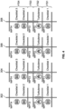
- the extent of the weather event indicator 214 is described. Note that there are four sequential flight segments, labeled FS1, FS2, FS3 and FS4, and that the flight segments extend between waypoints, as described above, and each flight segment is not the same size or distance.
- the weather event could be determined to start exactly at one waypoint and end exactly at another waypoint, in which case no further extent/duration processing would be required.
- the system 102 applies predetermined rules for showing the extent (and associated predicted duration).
- the system 102 e.g., via the display processing module 406 ) may calculate the distance associated with each flight segment and determine a distance that is equal to a snap-to start percent and a distance that is equal to a snap-to end percent for each of the flight segments.
- the system 102 will be determining whether weather events start prior to the first 15 NM of that flight segment; likewise, if the snap-to end is 90 %, the system 102 will be determining whether the weather event ends prior to the last 10 NM of the flight segment.
- the weather event indicator is aligned with the beginning of a flight segment.
- This example is depicted in FIG. 4 , on mission timelines 304 and 306 (note in each case the weather event indicator begins at the beginning of FS2, which visually conveys that the weather event starts (from the perspective of traveling toward it) within the first prescribed snap-to start percent of the flight segment FS2.
- the beginning of the weather event indicator is placed after the beginning of the flight segment when (i) the start of impact occurs after the first prescribed snap-to start percent of the flight segment (ii) the end of the weather event indicator occurs prior to a last prescribed snap-to end percent of the flight segment.
- the weather event occurs entirely within FS2.
- the beginning of the weather event indicator is placed at a center (i.e., midpoint) of the flight segment when the start of impact occurs after the first prescribed snap-to percent of the flight segment.
- the end of the weather event indicator is aligned with an ending of the flight segment when the end of impact occurs at or within to a final prescribed snap-to end percent of the flight segment (as shown on the mission timeline 304 ).
- the end of the weather event indicator is placed at the center of the flight segment (as shown on mission timeline 308 ) or before the ending of the flight segment (as shown on mission timeline 302 ) when the end of impact occurs prior to the last prescribed snap-to end percent of the flight segment.
- the determiner on where the end 218 of the weather event indicator 214 is placed has to do with whether the end of the weather event is in the same flight segment as the beginning (as it is in mission timeline 302 ) or in a different flight segment (as it is in mission timeline 308).
- mission timeline 308 the above processes may be expanded as follows.
- the flight segment is one of two or more flight segments displayed on the mission timeline 308 , and the controller is further configured to: identify a start flight segment corresponding to the beginning of the weather event; identify a stop flight segment corresponding to the end of the weather event; and wherein: the beginning of the weather event indicator is aligned with a beginning of the start flight segment when the start of impact occurs at or within the prescribed snap-to start percent of the flight segment; the beginning of the weather event indicator is placed after the beginning of the start flight segment when the start of impact occurs after the prescribed snap-to start percent of the flight segment; the end of the weather event indicator is aligned with an ending of the stop flight segment when the end of impact occurs after the prescribed snap-to end percent of the end of the flight segment; and the end of the weather event indicator is placed after the beginning of the weather event indicator and before the ending of the stop flight segment when the end of impact occurs at or before the prescribed snap-to end percent of the end of the flight segment.
- the weather phenomenon is one of a plurality of weather phenomena and the system 102 is further configured to: identify the plurality of weather phenomena.
- the system creates, for each of the plurality of weather phenomena, a respective information structure, and also identifies a respective weather interval for each of the plurality of weather phenomenon, the weather interval extending from a respective start of impact to a respective end of impact.
- each weather phenomenon may have its own interval, on occasion, they may overlap.
- the system 102 is configured to respond differently based on user selected (via user input device 108 ) or preprogrammed options for display processing submodules.
- the system 102 e.g., in the display processing module 406
- the system 102 may employ the prioritization scheme to overlay on the mission timeline a weather event indicator that depicts only a weather phenomenon with the highest priority in the prioritization scheme.
- the prioritization scheme may be preprogrammed into the rules in the program 134.
- the prioritization scheme may be a function of the system 102 , in which the system 102 processes aircraft sensor data or aircraft system status data (such as an amount of fuel) with at least the weather data.
- the display processing module 406 of the system 102 may be configured to, instead of prioritizing, group weather phenomenon together and generate a weather event indicator and an alphanumeric notice of the weather event that represent the grouped weather phenomenon.
- the display processing module 406 of the system 102 may be configured to: identify the plurality of weather phenomena; for each of the plurality of weather phenomena, create a respective information structure, and identify a weather interval extending from the start of impact to the end of impact; and, apply a fusion scheme to fuse incidents of a same subtype weather phenomena having weather intervals that overlap in the flight segment.
- the display processing module 406 of the system 102 may be configured to flatten some of the information in the information structure, using various fusion schemes.
- the system 102 may combine type and subtype (e.g., all thunderstorm-related).
- the system 102 combine subtype and severity (e.g. only a weather type).
- the system 102 may combine all weather events that have a same level of severity.
- the system 102 is further configured to: identify the plurality of weather phenomena; for each of the plurality of weather phenomena, create a respective information structure, and identify a weather interval extending from the start of impact to the end of impact; and, apply a fusion scheme to fuse incidents of a same subtype weather phenomena having weather intervals that overlap in the flight segment.
- any combination of the above fusion schemes may be employed.
- the system 102 may determine that a short distance exists between two similar weather phenomena. In such cases, the system 102 may compare the distance to a threshold, and if it is smaller than the threshold, the system 102 may fuse the two weather phenomena, such that the resulting weather event indicator extends from the beginning of the first one to the ending of the second one.
- FIGS. 3 and 4 show the mission timeline displayed in increments that are flight segments separated by waypoints.
- the mission timeline may be displayed in nonlinearly time-mapped flight segments.
- the techniques and processes described above can be applied to smaller intervals than a flight segment.
- a flight plan can be broken into intervals of any predefined length and the above processing can be applied to an interval in the same manner as it was applied to a flight segment.
- a single flight segment might comprise four intervals, and the snap-to percentages and other display processing techniques described above can be applied to each interval.
- the choice of interval or flight segment is based at least in part on the device selected for the display unit 110.
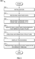
- method 500 may refer to elements and modules mentioned above in connection with FIGS. 1-2 .
- portions of method 500 may be performed by different components of the described system.
- method 500 may include any number of additional or alternative tasks, the tasks shown in FIG. 5 need notbe performed in the illustrated order, and method 500 may be incorporated into a more comprehensive procedure or method having additional functionality not described in detail herein.
- one or more of the tasks shown in FIG. 5 could be omitted from an embodiment of the method 500 as long as the intended overall functionality remains intact.
- Initialization may include loading instructions and program 134 into a processor within the controller circuit 104 , as well as loading preprogrammed variables 136 , map data, and aircraft-specific features into one or more database(s) 138.
- the system 102 receives weather data from at least one weather source.
- the system receives or references ownship data from onboard data sources.
- the ownship data includes FMS data, such as the flight plan (FP), aircraft state data from the geospatial sensors 118 , system status data, such as fuel status and an aircraft configuration, and optionally, onboard weather radar data.
- FMS data such as the flight plan (FP)
- aircraft state data from the geospatial sensors 118
- system status data such as fuel status and an aircraft configuration
- onboard weather radar data optionally, onboard weather radar data.
- the system 102 performs processing steps to identify one or more weather phenomenon that impacts the FP.
- the system creates an information structure for the weather phenomenon.
- the system 102 performs display processing to generate the weather event indicator and determine where on the displayed mission timeline its start and end will be.
- the system 102 also determines what alphanumeric notices to post alongside the weather event indicator.
- the system 102 presents the weather event indicator on the mission timeline displayed on the display unit 110 .
- Block 510 may be repeated for each weather phenomenon identified in block 508 .
- the system 102 is able to not only detect that a weather event is ahead, but to put weather data into context for the pilot, on an easy to comprehend visual, providing an objectively improved human-machine interface.
Landscapes
- Engineering & Computer Science (AREA)
- Aviation & Aerospace Engineering (AREA)
- Physics & Mathematics (AREA)
- General Physics & Mathematics (AREA)
- Traffic Control Systems (AREA)
Claims (14)
- Flugplan-, FP-, Anzeigesystem (102) in einem Flugzeug zum Automatisieren von Prozessen des Empfangens, Priorisierens und Gruppierens von Wetterdaten zu einem Wetterereignis mit einem damit verbundenen Ausmaß zur Darstellung auf einer angezeigten Missionszeitachse (202, 204), wobei das System eine Steuerschaltung (104) mit einem Prozessor umfasst, die durch Programmieren von Anweisungen auf nicht flüchtigen computerlesbaren Medien konfiguriert ist, wobei die Steuerschaltung dazu konfiguriert ist:Wetterdaten von mindestens einer Wetterquelle (122, 146) zu empfangen;Bezug auf Flugzeugstatusdaten und Flugzeugsystemstatusdaten zu nehmen; undein Wetterphänomen, das sich auf den FP auswirkt, durch Verarbeiten der Wetterdaten mit den Flugzeugstatusdaten, den Flugzeugsystemstatusdaten und dem FP zu identifizieren;eine Informationsstruktur für das Wetterphänomen zu erstellen, wobei die Informationsstruktur einen Typ, einen Untertyp, einen Schweregrad, einen Start der Auswirkung und ein Ende der Auswirkung beinhaltet;einen Wetterereignisindikator (214), der auf die Missionszeitachse gelegt wird, darzustellen, um das Wetterphänomen abzubilden, wobei die angezeigte Missionszeitachse vertikal ist und graphische Symbole (212) entlang der angezeigten Missionszeitachse an Orten platziert, die angeben, wann erforderliche Maßnahmen durchgeführt werden sollten und wann Situationen, die Aufmerksamkeit erfordern, auftreten könnten;einen alphanumerischen Hinweis (220) des Wetterereignisses neben dem Wetterereignisindikator darzustellen; undein Ausmaß des Wetterereignisses mit einem Beginn des Wetterereignisindikators (216) und einem Ende des Wetterereignisindikators (218) abzubilden;wobei:der Beginn des Wetterereignisindikators sich an einem Beginn eines Flugsegments (206, 208, 210) orientiert, wenn der Start der Auswirkung an oder innerhalb eines ersten vorgegebenen, am Start ausgerichteten Prozentsatzes des Flugsegments auftritt;der Beginn des Wetterereignisindikators nach dem Beginn des Flugsegments platziert wird, wenn (i) der Start der Auswirkung nach dem ersten vorgegebenen, am Start ausgerichteten Prozentsatz des Flugsegments auftritt, (ii) das Ende des Wetterereignisindikators vor einem letzten vorgegebenen, am Ende ausgerichteten Prozentsatz des Flugsegments auftritt;der Beginn des Wetterereignisindikators an einem Mittelpunkt des Flugsegments platziert ist, wenn der Start der Auswirkung nach dem vorgegebenen, am Start ausgerichteten Prozentsatz des Flugsegments auftritt;das Ende des Wetterereignisindikators sich an einem Schluss des Flugsegments orientiert, wenn das Ende der Auswirkung an oder innerhalb eines abschließenden vorgegebenen, am Ende ausgerichteten Prozentsatzes des Flugsegments auftritt; unddas Ende des Wetterereignisindikators an dem Mittelpunkt des Wetterereignisindikators oder vor dem Schluss des Flugsegments platziert ist, wenn das Ende der Auswirkung vor dem letzten vorgegebenen, am Ende ausgerichteten Prozentsatz des Flugsegments auftritt;wobei das Flugsegment eines aus zwei oder mehreren Flugsegmenten ist, die auf der Missionszeitachse angezeigt werden, und die Steuerung ferner dazu konfiguriert ist:ein Startflugsegment zu identifizieren, welches dem Beginn des Wetterereignisses entspricht;
ein Stopflugsegment zu identifizieren, welches dem Ende des Wetterereignisses entspricht;und wobei:der Beginn des Wetterereignisindikators sich an einem Beginn des Startflugsegments orientiert, wenn der Start der Auswirkung geringer als oder gleich einem vorgegebenen, am Start ausgerichteten Prozentsatz des Beginns des Startflugsegments ist;der Beginn des Wetterereignisindikators nach dem Beginn des Startflugsegments platziert ist, wenn der Start der Auswirkung größer als der vorgegebene, am Start ausgerichtete Prozentsatz des Beginns des Startflugsegments ist;das Ende des Wetterereignisindikators sich an einem Schluss des Stopflugsegments orientiert, wenn das Ende der Auswirkung größer als oder gleich einem vorgegebenen, am Ende ausgerichteten Prozentsatz des Schlusses des Stopflugsegments ist; unddas Ende des Wetterereignisindikators nach dem Beginn des Wetterereignisindikators und vor dem Schluss des Stopflugsegments platziert ist, wenn das Ende der Auswirkung geringer als der vorgegebene, am Ende ausgerichtete Prozentsatz des Schlusses des Stopflugsegments ist. - FP-Anzeigesystem nach Anspruch 1, wobei die mindestens eine Wetterquelle ein externes Wettersystem (146) und ein bordeigenes Wetterradarsystem (122) beinhaltet.
- FP-Anzeigesystem nach Anspruch 1, wobei die Steuerung ferner dazu konfiguriert ist: die Informationsstruktur als Antwort auf eine Änderung der Wetterdaten von der mindestens einen Wetterquelle neu zu erstellen.
- FP-Anzeigesystem nach Anspruch 3, wobei das Wetterphänomen eines aus einer Vielzahl von Wetterphänomenen ist und die Steuerung ferner dazu konfiguriert ist:die Vielzahl von Wetterphänomenen zu identifizieren;für jedes der Vielzahl von Wetterphänomenen eine jeweilige Informationsstruktur zu erstellen und ein jeweiliges Wetterintervall zu identifizieren, das sich von dem Start der Auswirkung bis zu dem Ende der Auswirkung erstreckt;ein Priorisierungsschema auf das Wetterphänomen mit Wetterintervallen, die sich in dem Flugsegment überlappen, anzuwenden; undwobei der Wetterereignisindikator, der auf die Missionszeitachse gelegt wird, ein Wetterphänomen mit einer höchsten Priorität des Priorisierungsschemas abbildet.
- FP-Anzeigesystem nach Anspruch 4, wobei das Priorisierungsschema eine Funktion eines Flugzeugsystemstatus ist, der von bordeigenen Sensoren (122) bereitgestellt wird.
- FP-Anzeigesystem nach Anspruch 3, wobei das Wetterphänomen eines aus einer Vielzahl von Wetterphänomenen ist und die Steuerung ferner dazu konfiguriert ist:die Vielzahl von Wetterphänomenen zu identifizieren;für jedes der Vielzahl von Wetterphänomenen eine jeweilige Informationsstruktur zu erstellen und ein Wetterintervall zu identifizieren, das sich von dem Start der Auswirkung bis zu dem Ende der Auswirkung erstreckt;ein Vereinigungsschema anzuwenden, um Ereignisse desselben Typs von Wetterphänomenen zu vereinigen, die Wetterintervalle aufweisen, die sich in dem Flugsegment überlappen; undwobei der Wetterereignisindikator, der auf die Missionszeitachse gelegt wird, den Typ des Wetterphänomens abbildet.
- FP-Anzeigesystem nach Anspruch 3, wobei das Wetterphänomen eines aus einer Vielzahl von Wetterphänomenen ist und die Steuerung ferner dazu konfiguriert ist:die Vielzahl von Wetterphänomenen zu identifizieren;für jedes der Vielzahl von Wetterphänomenen eine jeweilige Informationsstruktur zu erstellen und ein Wetterintervall zu identifizieren, das sich von dem Start der Auswirkung bis zu dem Ende der Auswirkung erstreckt;ein Vereinigungsschema anzuwenden, um Ereignisse desselben Untertyps von Wetterphänomenen zu vereinigen, die Wetterintervalle aufweisen, die sich in dem Flugsegment überlappen; undwobei der Wetterereignisindikator, der auf die Missionszeitachse gelegt wird, den Untertyp des Wetterphänomens abbildet.
- Verfahren zum Automatisieren von Prozessen des Empfangens, Priorisierens und Gruppierens von Wetterdaten zu einem Wetterereignis mit einem damit verbundenen Ausmaß zur Darstellung auf einer angezeigten Missionszeitachse (202, 204) in einem Flugzeug, das einen Flugplan, FP, aufweist, das Verfahren umfassend:Empfangen, durch eine Steuerschaltung (104) mit einem Prozessor (130), die durch Programmieren von Anweisungen konfiguriert ist, von Wetterdaten von mindestens einer Wetterquelle (122, 146);Bezugnehmen, durch die Steuerschaltung, auf Flugzeugstatusdaten und Flugzeugsystemstatusdaten; undIdentifizieren, durch die Steuerschaltung, eines Wetterphänomens, das sich auf den FP auswirkt, durch Verarbeiten der Wetterdaten mit den Flugzeugstatusdaten, den Flugzeugsystemstatusdaten und dem FP;Erstellen einer Informationsstruktur für das Wetterphänomen, wobei die Informationsstruktur einen Typ, einen Untertyp, einen Schweregrad, einen Start der Auswirkung und ein Ende der Auswirkung beinhaltet;Darstellen eines Wetterereignisindikators (214), der auf die Missionszeitachse gelegt wird, um das Wetterphänomen abzubilden, wobei die angezeigte Missionszeitachse vertikal ist und graphische Symbole (212) entlang der angezeigten Missionszeitachse an Orten platziert, die angeben, wann erforderliche Maßnahmen durchgeführt werden sollten und wann Situationen, die Aufmerksamkeit erfordern, auftreten könnten;Darstellen eines alphanumerischen Hinweises (220) des Wetterereignisses neben dem Wetterereignisindikator; undAbbilden eines Ausmaßes des Wetterereignisses mit einem Beginn des Wetterereignisindikators (216) und einem Ende des Wetterereignisindikators (218);wobei:der Beginn des Wetterereignisindikators sich an einem Beginn eines Flugsegments (206, 208, 210) orientiert, wenn der Start der Auswirkung an oder innerhalb eines ersten vorgegebenen, am Start ausgerichteten Prozentsatzes des Flugsegments auftritt;der Beginn des Wetterereignisindikators nach dem Beginn des Flugsegments platziert wird, wenn (i) der Start der Auswirkung nach dem ersten vorgegebenen, am Start ausgerichteten Prozentsatz des Flugsegments auftritt, (ii) das Ende des Wetterereignisindikators vor einem letzten vorgegebenen, am Ende ausgerichteten Prozentsatz des Flugsegments auftritt;der Beginn des Wetterereignisindikators an einem Mittelpunkt des Flugsegments platziert ist, wenn der Start der Auswirkung nach dem vorgegebenen, am Start ausgerichteten Prozentsatz des Flugsegments auftritt;das Ende des Wetterereignisindikators sich an einem Schluss des Flugsegments orientiert, wenn das Ende der Auswirkung an oder innerhalb eines abschließenden vorgegebenen, am Ende ausgerichteten Prozentsatzes des Flugsegments auftritt; unddas Ende des Wetterereignisindikators an dem Mittelpunkt des Wetterereignisindikators oder vor dem Schluss des Flugsegments platziert ist, wenn das Ende der Auswirkung vor dem letzten vorgegebenen, am Ende ausgerichteten Prozentsatz des Flugsegments auftritt;wobei:
wobei das Flugsegment eines aus zwei oder mehreren Flugsegmenten ist, die auf der Missionszeitachse angezeigt werden, und das Verfahren Folgendes beinhaltet:Identifizieren eines Startflugsegments, welches dem Beginn des Wetterereignisses entspricht;Identifizieren eines Stopflugsegments, welches dem Ende des Wetterereignisses entspricht;und wobei:der Beginn des Wetterereignisindikators sich an einem Beginn des Startflugsegments orientiert, wenn der Start der Auswirkung geringer als oder gleich einem vorgegebenen, am Start ausgerichteten Prozentsatz des Beginns des Startflugsegments ist;der Beginn des Wetterereignisindikators nach dem Beginn des Startflugsegments platziert ist, wenn der Start der Auswirkung größer als der vorgegebene, am Start ausgerichtete Prozentsatz des Beginns des Startflugsegments ist;das Ende des Wetterereignisindikators sich an einem Schluss des Stopflugsegments orientiert, wenn das Ende der Auswirkung größer als oder gleich einem vorgegebenen, am Ende ausgerichteten Prozentsatz des Schlusses des Stopflugsegments ist; unddas Ende des Wetterereignisindikators nach dem Beginn des Wetterereignisindikators und vor dem Schluss des Stopflugsegments platziert ist, wenn das Ende der Auswirkung geringer als der vorgegebene, am Ende ausgerichtete Prozentsatz des Schlusses des Stopflugsegments ist. - Verfahren nach Anspruch 8, wobei die mindestens eine Wetterquelle ein externes Wettersystem (146) und ein bordeigenes Wetterradarsystem (122) beinhaltet.
- Verfahren nach Anspruch 8, wobei die Steuerung ferner dazu konfiguriert ist: die Informationsstruktur als Antwort auf eine Änderung der Wetterdaten von der mindestens einen Wetterquelle neu zu erstellen.
- Verfahren nach Anspruch 10, wobei das Wetterphänomen eines aus einer Vielzahl von Wetterphänomenen ist und die Steuerung ferner dazu konfiguriert ist:die Vielzahl von Wetterphänomenen zu identifizieren;für jedes der Vielzahl von Wetterphänomenen eine jeweilige Informationsstruktur zu erstellen und ein jeweiliges Wetterintervall zu identifizieren, das sich von dem Start der Auswirkung bis zu dem Ende der Auswirkung erstreckt;ein Priorisierungsschema auf das Wetterphänomen mit Wetterintervallen, die sich in dem Flugsegment überlappen, anzuwenden; undwobei der Wetterereignisindikator, der auf die Missionszeitachse gelegt wird, ein Wetterphänomen mit einer höchsten Priorität abbildet.
- Verfahren nach Anspruch 11, ferner umfassend Basieren des Priorisierungsschemas auf einem von bordeigenen Sensoren bereitgestellten Flugzeugsystemstatus.
- Verfahren nach Anspruch 10, wobei das Wetterphänomen eines aus einer Vielzahl von Wetterphänomenen ist, und ferner umfassend:Identifizieren der Vielzahl von Wetterphänomenen;für jedes der Vielzahl von Wetterphänomenen, Erstellen einer jeweilige Informationsstruktur und Identifizieren eines jeweiligen Wetterintervalls, das sich von dem Start der Auswirkung bis zu dem Ende der Auswirkung erstreckt;Anwenden eines Vereinigungsschemas, um Ereignisse desselben Typs von Wetterphänomenen zu vereinigen, die Wetterintervalle aufweisen, die sich in dem Flugsegment überlappen; undwobei der Wetterereignisindikator, der auf die Missionszeitachse gelegt wird, den Typ des Wetterphänomens abbildet.
- Verfahren nach Anspruch 10, wobei das Wetterphänomen eines aus einer Vielzahl von Wetterphänomenen ist, und ferner umfassend:Identifizieren der Vielzahl von Wetterphänomenen;für jedes der Vielzahl von Wetterphänomenen, Erstellen einer jeweiligen Informationsstruktur und Identifizieren eines Wetterintervalls, das sich von dem Start der Auswirkung bis zu dem Ende der Auswirkung erstreckt;Anwenden eines Vereinigungsschemas, um Ereignisse desselben Untertyps von Wetterphänomenen zu vereinigen, die Wetterintervalle aufweisen, die sich in dem Flugsegment überlappen; undwobei der Wetterereignisindikator, der auf die Missionszeitachse gelegt wird, den Untertyp des Wetterphänomens abbildet.
Applications Claiming Priority (2)
| Application Number | Priority Date | Filing Date | Title |
|---|---|---|---|
| IN202011029904 | 2020-07-14 | ||
| US17/002,904 US11472567B2 (en) | 2020-07-14 | 2020-08-26 | Systems and methods for presenting environment information on a mission timeline |
Publications (2)
| Publication Number | Publication Date |
|---|---|
| EP3940673A1 EP3940673A1 (de) | 2022-01-19 |
| EP3940673B1 true EP3940673B1 (de) | 2024-10-30 |
Family
ID=76829383
Family Applications (1)
| Application Number | Title | Priority Date | Filing Date |
|---|---|---|---|
| EP21184121.8A Active EP3940673B1 (de) | 2020-07-14 | 2021-07-06 | Systeme und verfahren zur darstellung von umgebungsinformationen über eine missionszeitachse |
Country Status (1)
| Country | Link |
|---|---|
| EP (1) | EP3940673B1 (de) |
Families Citing this family (1)
| Publication number | Priority date | Publication date | Assignee | Title |
|---|---|---|---|---|
| CN119316376B (zh) * | 2024-12-11 | 2025-05-30 | 南京大桥机器有限公司 | 一种无人区自动气象站远程数据回传方法及系统 |
Family Cites Families (3)
| Publication number | Priority date | Publication date | Assignee | Title |
|---|---|---|---|---|
| US9666084B2 (en) * | 2014-12-19 | 2017-05-30 | Rockwell Collins, Inc. | Display and control of time evolved conditions relative to a vehicle |
| US9719785B2 (en) * | 2015-01-21 | 2017-08-01 | Honeywell International Inc. | Methods and systems for route-based display of meteorological forecast information |
| EP3660461B1 (de) * | 2018-11-27 | 2022-04-06 | Honeywell International Inc. | Systeme und verfahren zur unterstützung von abweichungen auf einer integrierten flugmanagementanzeige |
-
2021
- 2021-07-06 EP EP21184121.8A patent/EP3940673B1/de active Active
Also Published As
| Publication number | Publication date |
|---|---|
| EP3940673A1 (de) | 2022-01-19 |
Similar Documents
| Publication | Publication Date | Title |
|---|---|---|
| US11024181B2 (en) | Systems and methods for generating avionic displays including forecast overpressure event symbology | |
| US10699584B2 (en) | Systems and methods for sonic boom aware flight planning | |
| US12033517B2 (en) | Systems and methods for displaying off-board recharge station information for an urban air mobility (UAM) vehicle | |
| US7830276B2 (en) | System and method for displaying required navigational performance corridor on aircraft map display | |
| US20170183105A1 (en) | Display of meteorological data in aircraft | |
| US12530039B2 (en) | Systems and methods for promoting stable aircraft approach conditions | |
| US9972143B1 (en) | Systems and methods for trend monitoring and event prediction | |
| US10000297B2 (en) | Aircraft display systems and methods for generating horizontal situation indicator graphics with enhanced symbology | |
| US10529240B2 (en) | System and method for intelligently mining information and briefing an aircrew on conditions outside the aircraft | |
| EP4080485A1 (de) | Systeme und verfahren zur anzeige eines kombinierten warnsystems für die überrollung von start- und landebahnen (roaas) und für verkehrssymbole mit oberflächenanzeigen (surfia) | |
| US20230026834A1 (en) | Systems and methods for correlating a notice to airmen (notam) with a chart on an avionic display in a cockpit of an aircraft | |
| US12371184B2 (en) | Systems and methods for presenting a qualitative risk assessment for an aircraft to perform a flight procedure | |
| US11472567B2 (en) | Systems and methods for presenting environment information on a mission timeline | |
| EP3940673A1 (de) | Systeme und verfahren zur darstellung von umgebungsinformationen über eine missionszeitachse | |
| US11783717B2 (en) | Systems and methods for identifying a number of feasible target traffic for a paired approach | |
| EP3916358A1 (de) | Geländebewusstseins- und warnsystem (taw) und für ein fahrzeug für mobilität im urbanen luftraum (uamv) geeignete verfahren | |
| EP4130676B1 (de) | Systeme und verfahren zum korrelieren einer benachrichtigung für flugpersonal (notam) mit einer karte auf einer avionischen anzeige in einem cockpit eines flugzeugs | |
| US11676497B2 (en) | Systems and methods for for presenting an RTA waypoint with associated time constraints | |
| EP4618059A1 (de) | Systeme und verfahren zur förderung von stabilen flugzeuganflugszuständen | |
| US11787557B2 (en) | Methods and systems for representing a time scale on a cockpit display | |
| US20240203265A1 (en) | Systems and methods for performing impact assessment of avionic paramaters | |
| EP3923260B1 (de) | Systeme und verfahren zur anzeige von off-board-ladestationsinformationen für ein fahrzeug der urbanen luftmobilität (uam) | |
| EP4386713A1 (de) | Systeme und verfahren zur durchführung der auswirkungsbeurteilung von avionikparamatern | |
| EP4083576A1 (de) | Verfahren und systeme zum darstellen einer zeitskala auf einem cockpit-display | |
| EP4024371A1 (de) | Systeme und verfahren zur darstellung eines rta-wartepunkts mit zugehörigen zeitbeschränkungen |
Legal Events
| Date | Code | Title | Description |
|---|---|---|---|
| PUAI | Public reference made under article 153(3) epc to a published international application that has entered the european phase |
Free format text: ORIGINAL CODE: 0009012 |
|
| STAA | Information on the status of an ep patent application or granted ep patent |
Free format text: STATUS: THE APPLICATION HAS BEEN PUBLISHED |
|
| AK | Designated contracting states |
Kind code of ref document: A1 Designated state(s): AL AT BE BG CH CY CZ DE DK EE ES FI FR GB GR HR HU IE IS IT LI LT LU LV MC MK MT NL NO PL PT RO RS SE SI SK SM TR |
|
| RAP3 | Party data changed (applicant data changed or rights of an application transferred) |
Owner name: HONEYWELL INTERNATIONAL INC. |
|
| STAA | Information on the status of an ep patent application or granted ep patent |
Free format text: STATUS: REQUEST FOR EXAMINATION WAS MADE |
|
| 17P | Request for examination filed |
Effective date: 20220708 |
|
| RBV | Designated contracting states (corrected) |
Designated state(s): AL AT BE BG CH CY CZ DE DK EE ES FI FR GB GR HR HU IE IS IT LI LT LU LV MC MK MT NL NO PL PT RO RS SE SI SK SM TR |
|
| P01 | Opt-out of the competence of the unified patent court (upc) registered |
Effective date: 20230421 |
|
| GRAP | Despatch of communication of intention to grant a patent |
Free format text: ORIGINAL CODE: EPIDOSNIGR1 |
|
| STAA | Information on the status of an ep patent application or granted ep patent |
Free format text: STATUS: GRANT OF PATENT IS INTENDED |
|
| INTG | Intention to grant announced |
Effective date: 20240607 |
|
| GRAS | Grant fee paid |
Free format text: ORIGINAL CODE: EPIDOSNIGR3 |
|
| GRAA | (expected) grant |
Free format text: ORIGINAL CODE: 0009210 |
|
| STAA | Information on the status of an ep patent application or granted ep patent |
Free format text: STATUS: THE PATENT HAS BEEN GRANTED |
|
| AK | Designated contracting states |
Kind code of ref document: B1 Designated state(s): AL AT BE BG CH CY CZ DE DK EE ES FI FR GB GR HR HU IE IS IT LI LT LU LV MC MK MT NL NO PL PT RO RS SE SI SK SM TR |
|
| REG | Reference to a national code |
Ref country code: GB Ref legal event code: FG4D |
|
| REG | Reference to a national code |
Ref country code: CH Ref legal event code: EP |
|
| REG | Reference to a national code |
Ref country code: IE Ref legal event code: FG4D |
|
| REG | Reference to a national code |
Ref country code: DE Ref legal event code: R096 Ref document number: 602021020893 Country of ref document: DE |
|
| REG | Reference to a national code |
Ref country code: LT Ref legal event code: MG9D |
|
| REG | Reference to a national code |
Ref country code: NL Ref legal event code: MP Effective date: 20241030 |
|
| PG25 | Lapsed in a contracting state [announced via postgrant information from national office to epo] |
Ref country code: IS Free format text: LAPSE BECAUSE OF FAILURE TO SUBMIT A TRANSLATION OF THE DESCRIPTION OR TO PAY THE FEE WITHIN THE PRESCRIBED TIME-LIMIT Effective date: 20250228 Ref country code: PT Free format text: LAPSE BECAUSE OF FAILURE TO SUBMIT A TRANSLATION OF THE DESCRIPTION OR TO PAY THE FEE WITHIN THE PRESCRIBED TIME-LIMIT Effective date: 20250228 Ref country code: HR Free format text: LAPSE BECAUSE OF FAILURE TO SUBMIT A TRANSLATION OF THE DESCRIPTION OR TO PAY THE FEE WITHIN THE PRESCRIBED TIME-LIMIT Effective date: 20241030 |
|
| PG25 | Lapsed in a contracting state [announced via postgrant information from national office to epo] |
Ref country code: FI Free format text: LAPSE BECAUSE OF FAILURE TO SUBMIT A TRANSLATION OF THE DESCRIPTION OR TO PAY THE FEE WITHIN THE PRESCRIBED TIME-LIMIT Effective date: 20241030 Ref country code: NL Free format text: LAPSE BECAUSE OF FAILURE TO SUBMIT A TRANSLATION OF THE DESCRIPTION OR TO PAY THE FEE WITHIN THE PRESCRIBED TIME-LIMIT Effective date: 20241030 |
|
| REG | Reference to a national code |
Ref country code: AT Ref legal event code: MK05 Ref document number: 1737731 Country of ref document: AT Kind code of ref document: T Effective date: 20241030 |
|
| PG25 | Lapsed in a contracting state [announced via postgrant information from national office to epo] |
Ref country code: BG Free format text: LAPSE BECAUSE OF FAILURE TO SUBMIT A TRANSLATION OF THE DESCRIPTION OR TO PAY THE FEE WITHIN THE PRESCRIBED TIME-LIMIT Effective date: 20241030 |
|
| PG25 | Lapsed in a contracting state [announced via postgrant information from national office to epo] |
Ref country code: ES Free format text: LAPSE BECAUSE OF FAILURE TO SUBMIT A TRANSLATION OF THE DESCRIPTION OR TO PAY THE FEE WITHIN THE PRESCRIBED TIME-LIMIT Effective date: 20241030 |
|
| PG25 | Lapsed in a contracting state [announced via postgrant information from national office to epo] |
Ref country code: NO Free format text: LAPSE BECAUSE OF FAILURE TO SUBMIT A TRANSLATION OF THE DESCRIPTION OR TO PAY THE FEE WITHIN THE PRESCRIBED TIME-LIMIT Effective date: 20250130 |
|
| PG25 | Lapsed in a contracting state [announced via postgrant information from national office to epo] |
Ref country code: AT Free format text: LAPSE BECAUSE OF FAILURE TO SUBMIT A TRANSLATION OF THE DESCRIPTION OR TO PAY THE FEE WITHIN THE PRESCRIBED TIME-LIMIT Effective date: 20241030 Ref country code: GR Free format text: LAPSE BECAUSE OF FAILURE TO SUBMIT A TRANSLATION OF THE DESCRIPTION OR TO PAY THE FEE WITHIN THE PRESCRIBED TIME-LIMIT Effective date: 20250131 Ref country code: LV Free format text: LAPSE BECAUSE OF FAILURE TO SUBMIT A TRANSLATION OF THE DESCRIPTION OR TO PAY THE FEE WITHIN THE PRESCRIBED TIME-LIMIT Effective date: 20241030 |
|
| PG25 | Lapsed in a contracting state [announced via postgrant information from national office to epo] |
Ref country code: PL Free format text: LAPSE BECAUSE OF FAILURE TO SUBMIT A TRANSLATION OF THE DESCRIPTION OR TO PAY THE FEE WITHIN THE PRESCRIBED TIME-LIMIT Effective date: 20241030 |
|
| PG25 | Lapsed in a contracting state [announced via postgrant information from national office to epo] |
Ref country code: RS Free format text: LAPSE BECAUSE OF FAILURE TO SUBMIT A TRANSLATION OF THE DESCRIPTION OR TO PAY THE FEE WITHIN THE PRESCRIBED TIME-LIMIT Effective date: 20250130 |
|
| PG25 | Lapsed in a contracting state [announced via postgrant information from national office to epo] |
Ref country code: SM Free format text: LAPSE BECAUSE OF FAILURE TO SUBMIT A TRANSLATION OF THE DESCRIPTION OR TO PAY THE FEE WITHIN THE PRESCRIBED TIME-LIMIT Effective date: 20241030 |
|
| PG25 | Lapsed in a contracting state [announced via postgrant information from national office to epo] |
Ref country code: DK Free format text: LAPSE BECAUSE OF FAILURE TO SUBMIT A TRANSLATION OF THE DESCRIPTION OR TO PAY THE FEE WITHIN THE PRESCRIBED TIME-LIMIT Effective date: 20241030 |
|
| PG25 | Lapsed in a contracting state [announced via postgrant information from national office to epo] |
Ref country code: EE Free format text: LAPSE BECAUSE OF FAILURE TO SUBMIT A TRANSLATION OF THE DESCRIPTION OR TO PAY THE FEE WITHIN THE PRESCRIBED TIME-LIMIT Effective date: 20241030 |
|
| PG25 | Lapsed in a contracting state [announced via postgrant information from national office to epo] |
Ref country code: RO Free format text: LAPSE BECAUSE OF FAILURE TO SUBMIT A TRANSLATION OF THE DESCRIPTION OR TO PAY THE FEE WITHIN THE PRESCRIBED TIME-LIMIT Effective date: 20241030 |
|
| PG25 | Lapsed in a contracting state [announced via postgrant information from national office to epo] |
Ref country code: SK Free format text: LAPSE BECAUSE OF FAILURE TO SUBMIT A TRANSLATION OF THE DESCRIPTION OR TO PAY THE FEE WITHIN THE PRESCRIBED TIME-LIMIT Effective date: 20241030 |
|
| PG25 | Lapsed in a contracting state [announced via postgrant information from national office to epo] |
Ref country code: CZ Free format text: LAPSE BECAUSE OF FAILURE TO SUBMIT A TRANSLATION OF THE DESCRIPTION OR TO PAY THE FEE WITHIN THE PRESCRIBED TIME-LIMIT Effective date: 20241030 |
|
| PG25 | Lapsed in a contracting state [announced via postgrant information from national office to epo] |
Ref country code: IT Free format text: LAPSE BECAUSE OF FAILURE TO SUBMIT A TRANSLATION OF THE DESCRIPTION OR TO PAY THE FEE WITHIN THE PRESCRIBED TIME-LIMIT Effective date: 20241030 |
|
| REG | Reference to a national code |
Ref country code: DE Ref legal event code: R097 Ref document number: 602021020893 Country of ref document: DE |
|
| PLBE | No opposition filed within time limit |
Free format text: ORIGINAL CODE: 0009261 |
|
| STAA | Information on the status of an ep patent application or granted ep patent |
Free format text: STATUS: NO OPPOSITION FILED WITHIN TIME LIMIT |
|
| PG25 | Lapsed in a contracting state [announced via postgrant information from national office to epo] |
Ref country code: SE Free format text: LAPSE BECAUSE OF FAILURE TO SUBMIT A TRANSLATION OF THE DESCRIPTION OR TO PAY THE FEE WITHIN THE PRESCRIBED TIME-LIMIT Effective date: 20241030 |
|
| 26N | No opposition filed |
Effective date: 20250731 |
|
| PGFP | Annual fee paid to national office [announced via postgrant information from national office to epo] |
Ref country code: FR Payment date: 20250725 Year of fee payment: 5 |
|
| REG | Reference to a national code |
Ref country code: DE Ref legal event code: R119 Ref document number: 602021020893 Country of ref document: DE |
|
| REG | Reference to a national code |
Ref country code: CH Ref legal event code: H13 Free format text: ST27 STATUS EVENT CODE: U-0-0-H10-H13 (AS PROVIDED BY THE NATIONAL OFFICE) Effective date: 20260224 |
|
| PG25 | Lapsed in a contracting state [announced via postgrant information from national office to epo] |
Ref country code: LU Free format text: LAPSE BECAUSE OF NON-PAYMENT OF DUE FEES Effective date: 20250706 |
|
| GBPC | Gb: european patent ceased through non-payment of renewal fee |
Effective date: 20250706 |
|
| REG | Reference to a national code |
Ref country code: BE Ref legal event code: MM Effective date: 20250731 |
|
| PG25 | Lapsed in a contracting state [announced via postgrant information from national office to epo] |
Ref country code: GB Free format text: LAPSE BECAUSE OF NON-PAYMENT OF DUE FEES Effective date: 20250706 |
|
| PG25 | Lapsed in a contracting state [announced via postgrant information from national office to epo] |
Ref country code: DE Free format text: LAPSE BECAUSE OF NON-PAYMENT OF DUE FEES Effective date: 20260203 |
|
| PG25 | Lapsed in a contracting state [announced via postgrant information from national office to epo] |
Ref country code: BE Free format text: LAPSE BECAUSE OF NON-PAYMENT OF DUE FEES Effective date: 20250731 |
|
| PG25 | Lapsed in a contracting state [announced via postgrant information from national office to epo] |
Ref country code: CH Free format text: LAPSE BECAUSE OF NON-PAYMENT OF DUE FEES Effective date: 20250731 |