EP3940404A1 - Battery resistance diagnosis device and method - Google Patents
Battery resistance diagnosis device and method Download PDFInfo
- Publication number
- EP3940404A1 EP3940404A1 EP20843926.5A EP20843926A EP3940404A1 EP 3940404 A1 EP3940404 A1 EP 3940404A1 EP 20843926 A EP20843926 A EP 20843926A EP 3940404 A1 EP3940404 A1 EP 3940404A1
- Authority
- EP
- European Patent Office
- Prior art keywords
- battery
- resistance value
- calculated
- resistance
- external resistance
- Prior art date
- Legal status (The legal status is an assumption and is not a legal conclusion. Google has not performed a legal analysis and makes no representation as to the accuracy of the status listed.)
- Granted
Links
Images




Classifications
-
- G—PHYSICS
- G01—MEASURING; TESTING
- G01R—MEASURING ELECTRIC VARIABLES; MEASURING MAGNETIC VARIABLES
- G01R31/00—Arrangements for testing electric properties; Arrangements for locating electric faults; Arrangements for electrical testing characterised by what is being tested not provided for elsewhere
- G01R31/36—Arrangements for testing, measuring or monitoring the electrical condition of accumulators or electric batteries, e.g. capacity or state of charge [SoC]
- G01R31/389—Measuring internal impedance, internal conductance or related variables
-
- G—PHYSICS
- G01—MEASURING; TESTING
- G01R—MEASURING ELECTRIC VARIABLES; MEASURING MAGNETIC VARIABLES
- G01R27/00—Arrangements for measuring resistance, reactance, impedance, or electric characteristics derived therefrom
- G01R27/02—Measuring real or complex resistance, reactance, impedance, or other two-pole characteristics derived therefrom, e.g. time constant
- G01R27/14—Measuring resistance by measuring current or voltage obtained from a reference source
-
- G—PHYSICS
- G01—MEASURING; TESTING
- G01R—MEASURING ELECTRIC VARIABLES; MEASURING MAGNETIC VARIABLES
- G01R31/00—Arrangements for testing electric properties; Arrangements for locating electric faults; Arrangements for electrical testing characterised by what is being tested not provided for elsewhere
- G01R31/36—Arrangements for testing, measuring or monitoring the electrical condition of accumulators or electric batteries, e.g. capacity or state of charge [SoC]
- G01R31/3644—Constructional arrangements
- G01R31/3648—Constructional arrangements comprising digital calculation means, e.g. for performing an algorithm
-
- G—PHYSICS
- G01—MEASURING; TESTING
- G01R—MEASURING ELECTRIC VARIABLES; MEASURING MAGNETIC VARIABLES
- G01R31/00—Arrangements for testing electric properties; Arrangements for locating electric faults; Arrangements for electrical testing characterised by what is being tested not provided for elsewhere
- G01R31/36—Arrangements for testing, measuring or monitoring the electrical condition of accumulators or electric batteries, e.g. capacity or state of charge [SoC]
- G01R31/382—Arrangements for monitoring battery or accumulator variables, e.g. SoC
- G01R31/3835—Arrangements for monitoring battery or accumulator variables, e.g. SoC involving only voltage measurements
-
- G—PHYSICS
- G01—MEASURING; TESTING
- G01R—MEASURING ELECTRIC VARIABLES; MEASURING MAGNETIC VARIABLES
- G01R31/00—Arrangements for testing electric properties; Arrangements for locating electric faults; Arrangements for electrical testing characterised by what is being tested not provided for elsewhere
- G01R31/36—Arrangements for testing, measuring or monitoring the electrical condition of accumulators or electric batteries, e.g. capacity or state of charge [SoC]
- G01R31/392—Determining battery ageing or deterioration, e.g. state of health
-
- G—PHYSICS
- G01—MEASURING; TESTING
- G01R—MEASURING ELECTRIC VARIABLES; MEASURING MAGNETIC VARIABLES
- G01R31/00—Arrangements for testing electric properties; Arrangements for locating electric faults; Arrangements for electrical testing characterised by what is being tested not provided for elsewhere
- G01R31/36—Arrangements for testing, measuring or monitoring the electrical condition of accumulators or electric batteries, e.g. capacity or state of charge [SoC]
- G01R31/396—Acquisition or processing of data for testing or for monitoring individual cells or groups of cells within a battery
-
- Y—GENERAL TAGGING OF NEW TECHNOLOGICAL DEVELOPMENTS; GENERAL TAGGING OF CROSS-SECTIONAL TECHNOLOGIES SPANNING OVER SEVERAL SECTIONS OF THE IPC; TECHNICAL SUBJECTS COVERED BY FORMER USPC CROSS-REFERENCE ART COLLECTIONS [XRACs] AND DIGESTS
- Y02—TECHNOLOGIES OR APPLICATIONS FOR MITIGATION OR ADAPTATION AGAINST CLIMATE CHANGE
- Y02E—REDUCTION OF GREENHOUSE GAS [GHG] EMISSIONS, RELATED TO ENERGY GENERATION, TRANSMISSION OR DISTRIBUTION
- Y02E60/00—Enabling technologies; Technologies with a potential or indirect contribution to GHG emissions mitigation
- Y02E60/10—Energy storage using batteries
Definitions
- the present invention relates to a battery resistance diagnosis device and method for diagnosing a resistance abnormality by detecting a sudden change in resistance in a battery cell and a battery sensing line.
- a threshold value is defined as a maximum value in consideration of this fact, and the battery system operates with a fixed threshold value during the life cycle of the system.
- the deviation according to the production of battery products is also not reflected in the threshold value, and the threshold value may be set excessively large in the Golden Sample standard.
- the present invention is to provide a battery resistance diagnosis device and method for detecting the resistance of the battery cells when each battery cell has the same voltage and current, that is, when in a fully charged state, to accurately diagnose the sudden change in resistance of the battery cell, and for diagnosing resistance due to cell voltage measurement errors to contribute to more accurate cell voltage measurements.
- a battery resistance diagnosis device includes a current supply unit configured to supply a preset fixed current to a battery cell, a voltage measurement unit configured to measure an open circuit voltage of the battery cell while the fixed current is supplied, an external resistance calculation unit configured to calculate an external resistance value of the battery based on the fixed current and the open circuit voltage of the battery cell, and an abnormality diagnosis unit configured to diagnose a battery abnormality due to a voltage drop by comparing the calculated external resistance value with a preset external resistance value.
- the voltage measurement unit may measure the open circuit voltage of the battery cell with a predetermined period
- the battery resistance diagnosis device may include a memory for accumulating and storing an external resistance value calculated in a predetermined period based on the open circuit voltage of the battery cell measured in the predetermined period.
- the preset resistance value may be an external resistance value initially calculated by the external resistance calculation unit after the battery cell is fully charged, wherein the abnormality diagnosis unit may diagnose a battery abnormality based on whether a difference between the calculated external resistance value and the preset resistance value is out of a predetermined range.
- the predetermined range may be 10% of the external resistance value initially calculated in the external resistance calculation unit.
- the preset external resistance value may be an external resistance value calculated in a calculation period and stored in the memory before the calculated external resistance value is calculated among external resistance values calculated in a predetermined period stored in the memory, wherein the abnormality diagnosis unit may diagnose a battery abnormality based on whether an amount of change from the preset external resistance value to the calculated external resistance value is out of a predetermined range.
- the predetermined range may be 200% of the amount of change to the resistance value stored in the memory in the calculation period immediately before the calculated external resistance value is calculated.
- the resistance value of the battery may include at least one resistance value among an internal resistance of the battery cell, a lead resistance of a connection part of the battery cell, a busbar resistance, a flexible printed circuit (FPC) resistance, a printed circuit board (PCB) resistance, and a connector resistance.
- FPC flexible printed circuit
- PCB printed circuit board
- the preset fixed current may be a balancing current of the battery.
- the method includes supplying a preset fixed current to a battery cell, measuring an open circuit voltage of the battery cell while the fixed current is supplied, calculating an external resistance value of the battery based on the fixed current and the open circuit voltage of the battery cell, and diagnosing a battery abnormality due to a voltage drop by comparing the calculated external resistance value with a preset external resistance value.
- the measuring of the open circuit voltage of the battery cell may include measuring the open circuit voltage of the battery cell in a predetermined period, wherein the method may further include accumulating and storing in a memory an external resistance value calculated in a predetermined period based on the open circuit voltage of the battery cell measured in the predetermined period.
- the preset resistance value may be an external resistance value initially calculated after the battery cell is fully charged, wherein the diagnosing of the battery abnormality may include diagnosing a battery abnormality based on whether a difference between the calculated external resistance value and the preset resistance value is out of a predetermined range.
- the predetermined range may be 10% of the initially calculated external resistance value.
- the preset external resistance value may be an external resistance value calculated in a calculation period and stored in the memory before the calculated external resistance value is calculated among external resistance values calculated in a predetermined period stored in the memory, wherein the diagnosing of the battery abnormality may include diagnosing a battery abnormality based on whether an amount of change from the preset external resistance value to the calculated external resistance value is out of a predetermined range.
- the predetermined range may be 200% of the amount of change to the resistance value stored in the memory in the calculation period immediately before the calculated external resistance value is calculated.
- the resistance value of the battery may include at least one resistance value among an internal resistance of the battery cell, a lead resistance of a connection part of the battery cell, a busbar resistance, a FPC resistance, a PCB resistance, and a connector resistance.
- the preset fixed current may be a balancing current of the battery.
- a battery resistance diagnosis device and method of the present invention it is possible to detect the resistance of the battery cells when each battery cell has the same voltage and current, that is, when in a fully charged state, to accurately diagnose the sudden change in resistance of the battery cell, and diagnose resistance due to cell voltage measurement errors to contribute to more accurate cell voltage measurements.
- first, second, first, or second used in various embodiments may modify various elements regardless of their order and/or importance, and do not limit the corresponding elements.
- a first component may be referred to as a second component, and similarly, a second component may be renamed and referred to as a first component.
- FIG. 1 is a block diagram showing the configuration of a general battery management system.
- FIG. 1 a configuration diagram schematically shows a battery control system including a battery pack 1 and an upper-level controller 2 included in an upper-level system according to an embodiment of the present invention.
- the battery pack 1 includes a battery module 10 consisting of one or more battery cells and capable of charging and discharging, a switching unit 14 connected in series to the + terminal side or the - terminal side of the battery module 10 to control the charge/discharge current flow of the battery module 10, and a battery management system 20 for controlling and managing the voltage, current, temperature, and the like of the battery module 10 to prevent overcharging and overdischarging.
- the battery management system 20 is described as being connected to the battery module, it is connected for each battery cell to monitor and measure the voltage and current temperature of the battery cells.
- a battery cell management system (not shown) is arranged for each battery cell, and each of the plurality of battery cell management systems may transmit and receive data to and from the battery management system 20 that monitors and controls the battery module.
- the battery cell management system is similar in operation and function to the battery management system 20.
- the switching unit 14 is a semiconductor switching element for controlling the current flow for charging or discharging the battery module 10, and, for example, at least one MOSFET may be used.
- the BMS 20 may measure or calculate voltages and currents such as gates, sources, and drains of semiconductor switching elements, and in addition, measure the current, voltage, temperature, and the like of the battery module using the sensor 12 provided adjacent to the semiconductor switching element 14.
- the BMS 20 is an interface for receiving values obtained by measuring the above-described various parameters, and may include a plurality of terminals and a circuit connected to these terminals to process input values.
- the BMS 20 may control ON/OFF of the switching element 14, for example, a MOSFET, and may be connected to the battery module 10 to monitor the state of the battery module 10.
- the switching element 14 for example, a MOSFET
- the upper-level controller 2 may transmit a control signal for the battery module to the BMS 20. Accordingly, the operation of the BMS 20 may be controlled based on a signal applied from the upper-level controller.
- the battery cell of the present invention may be included in a battery pack used for an ESS or a vehicle. However, it is not limited to these uses.
- the battery cell diagnosis device may be connected to each of a plurality of battery cells connected in series in the battery module 10 to determine an abnormality of the battery cell.
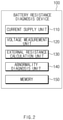
- FIG. 2 is a block diagram showing the configuration of a battery resistance diagnosis device according to an embodiment of the present invention.
- the battery resistance diagnosis device 100 includes a current supply unit 110, a voltage measurement unit 120, an external resistance calculation unit 130, an abnormality diagnosis unit 140, and a memory 150.
- the current supply unit 110 may supply a preset fixed current to the battery cell.
- the fixed current supplied from the current supply unit 110 may be a current used in a balancing circuit (not shown) of a battery.
- the balancing circuit of the battery as a circuit consisting of a resistor and a switching element connected to both ends of each battery cell, refers to a circuit that regulates the voltage of each battery cell to match by controlling the switching element to be ON/OFF under the control of the Battery Management System (BMS), and consuming the balancing current of the battery cell through resistance to reduce the voltage.
- BMS Battery Management System
- the battery resistance diagnosis device 100 when a battery cell is fully charged, measurement may be performed in a state in which the battery is open circuit voltage (OCV).
- OCV open circuit voltage
- the current supply unit 110 performs a measurement when each battery cell is fully charged (for example, before the sleep mode), that is, when each battery cell has the same voltage and the same current, so that it is possible to make the diagnosis more accurately.
- the voltage measurement unit 120 may measure an OCV of a battery cell while a fixed current is supplied by the current supply unit 110. In this case, the voltage measurement unit 120 may measure the voltage generated when the fixed current used in the existing battery balancing circuit is supplied to the resistance of the battery cell and the sensing line by the current supply unit 110.
- the voltage measurement unit 120 may measure OCV of the battery cell at a predetermined period.
- the measurement period may be arbitrarily set by the user of the battery resistance diagnosis device 100 according to an embodiment of the present invention.
- the external resistance calculation unit 130 may calculate an external resistance value of the battery based on the fixed current supplied by the current supply unit 110 and the OCV of the battery cell measured by the voltage measurement unit 120. For example, the external resistance calculation unit 130 may calculate the external resistance value of the battery cell by dividing the OCV when the battery is fully charged (100%) by the current of the balancing circuit.
- the external resistance value of the battery cell may include at least one resistance value of lead resistance, busbar resistance, Flexible Printed Circuit (FPC) resistance, Printed Circuit Board (PCB) resistance, and connector resistance at the connection part of the battery cell in addition to the internal resistance of the battery cell. This will be described later with reference to FIG. 3 .
- FPC Flexible Printed Circuit
- PCB Printed Circuit Board
- the external resistance calculation unit 130 may calculate a change in the resistance value based on a difference between the calculated external resistance value (i.e., the external resistance value calculated in the calculation period before the external resistance value is calculated in the external resistance calculation unit 130) and the external resistance value previously stored in the memory 150.
- the amount of change in the resistance value may be a difference between the external resistance value currently calculated and the external resistance value calculated in the immediately previous calculation period stored in the memory 150.
- the abnormality diagnosis unit 140 may diagnose a battery abnormality due to a voltage drop by comparing the external resistance value calculated by the external resistance calculation unit 130 with a preset external resistance value.
- the abnormality diagnosis unit 140 may diagnose a battery abnormality based on whether the difference between the resistance value calculated by the external resistance calculation unit 130 and the resistance value (i.e., the resistance value initially stored in the memory 150) initially calculated by the external resistance calculation unit 130 after the battery cell is fully charged is out of a predetermined range.
- the external resistance value initially calculated by the external resistance calculation unit 130 may be stored in the memory 150.
- the predetermined range may be 10% of the external resistance value initially calculated by the external resistance calculation unit 130.
- the abnormality diagnosis unit 140 may diagnose a battery abnormality based on whether a change amount of the external resistance value calculated by the external resistance calculation unit 130 is out of a predetermined range.
- the amount of change in the external resistance value may include the amount of change from the external resistance value calculated in the calculation period before the calculated external resistance value is calculated and stored in the memory to the resistance value calculated by the external resistance calculation unit 130.
- the predetermined range may be 200% of the change amount (i.e., the amount of change in the external resistance value calculated in the previous calculation period) to the resistance value calculated in the calculation period immediately before the external resistance value is calculated by the external resistance calculation unit 130.
- the abnormality diagnosis unit 140 may analyze patterns such as trends or fluctuations of changes in external resistance values and external resistance values through various analysis techniques such as machine learning or big data analysis, and diagnose an abnormality in the battery by detecting whether it deviates from the normal pattern.
- the memory 150 may accumulate and store an external resistance value calculated in a predetermined period and a change amount of the external resistance value based on the OCV of the battery cell measured in a predetermined period by the voltage measurement unit 120 Accordingly, the abnormality diagnosis unit 140 may determine whether the battery is abnormal using an external resistance value stored in the memory 150. In this case, a period in which the memory 150 stores the external resistance value and the amount of change in the external resistance value may be arbitrarily set by the user of the battery resistance diagnosis device 100 according to an embodiment of the present invention.
- the battery resistance diagnosis device it is possible to detect the resistance of the battery cells when each battery cell has the same voltage and current, that is, when in a fully charged state, to accurately diagnose the sudden change in resistance of the battery cell, and diagnose resistance due to cell voltage measurement errors to contribute to more accurate cell voltage measurements.
- FIG. 3 shows a resistance configuration of a battery cell voltage measurement terminal according to an embodiment of the present invention.
- a battery cell voltage measurement terminal 30 may include a battery cell 31, a sensing line 32, and a Cell Management Controller (CMC) 33.
- CMC Cell Management Controller
- the battery resistance diagnosis device it is possible to measure all external resistance elements such as lead resistance 2, busbar resistance 3, FPC plate resistance 4, FPC connection part resistance5, and PCB pattern and connector resistance 6 at the connection part of the battery cell included in the sensing line 32 between the battery cell 31 and the CMC 33 in addition to the internal voltage 1 of the battery cell 31.
- the resistance elements shown in FIG. 3 are only exemplary, and any resistance elements that affect the increase (deterioration) of the resistance of the battery cell 31 may be included.
- the CMC 33 may be a slave battery management system (BMS).
- BMS slave battery management system
- a slave battery management system is disposed in each battery cell.
- Each slave battery management system measures and monitors the temperature, voltage, or current of a plurality of battery cells, and transmits the monitored information to the upper-level system, and controls the connected battery cell by receiving a control command of the battery cell in the upper-level system.
- the CMC 33 shown in FIG. 3 may include a processor that performs the battery cell diagnosis function described with reference to FIG. 2 .
- the CMC is provided with a balancing circuit of the battery cells, so that a fixed current can be supplied to the battery cells to calculate resistance.
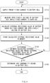
- FIG. 4 is a flowchart of a method for diagnosing battery resistance according to an embodiment of the present invention.
- a preset fixed current is supplied to the battery cell (S110).
- the supplied fixed current may be a current used in the balancing circuit of the battery.
- diagnosis may be performed under the same voltage and current. Accordingly, in a conventional battery system, measurement errors due to differences in voltage, SOC, current, and the like for each battery cell can be reduced.
- the OCV of the battery cell is measured (S120).
- a voltage generated when a fixed current used in a conventional balancing circuit of a battery is supplied to a resistance such as a battery cell and a sensing line may be measured.
- the OCV of the battery cell may be measured in a predetermined period. In this case, the measurement period may be arbitrarily set by a user of the battery resistance diagnosis device according to an embodiment of the present invention.
- an external resistance value of the battery is calculated based on the fixed current and OCV of the battery cell (S130).
- the external resistance value of the battery cell can be calculated by dividing the OCV at the time of full charge (100%) by the current of the balancing circuit.
- the external resistance value calculated in operation S130 is stored in the memory.
- the preset external resistance value may include an external resistance value initially calculated after the battery cell is fully charged (i.e., a resistance value initially stored in the memory 150).
- the predetermined range may be 10% of the initially calculated external resistance value.
- FIG. 5 is a flowchart of a method for diagnosing battery resistance according to another embodiment of the present invention.
- a change amount of the external resistance value is calculated based on a difference between the calculated external resistance value and the external resistance value stored in the memory in a calculation period before the calculated external resistance value is calculated.
- the amount of change in the external resistance value may be a difference between the current calculated resistance value and the resistance value calculated in the immediately previous calculation period stored in the memory. Then, the calculated change amount of the external resistance value is stored in the memory (S250).
- the predetermined range may be 200% of the change amount (i.e., the amount of change in the external resistance value calculated in the immediately previous calculation period) to the resistance value stored in the memory in the calculation period immediately before the external resistance value is calculated.
- step S260 If the external resistance value calculated in step S260 is out of a predetermined range (YES), it is determined that an abnormality has occurred in the battery cell (S270).
- the battery resistance diagnosis method it is possible to detect the resistance of the battery cells when each battery cell has the same voltage and current, that is, when in a fully charged state, to accurately diagnose the sudden change in resistance of the battery cell, and diagnose resistance due to cell voltage measurement errors to contribute to more accurate cell voltage measurements.
- FIG. 6 is a block diagram showing a hardware configuration of a battery resistance diagnosis device according to an embodiment of the present invention.
- the battery resistance diagnosis device 600 may include a microcontroller (MCU) 610 that controls various processes and configurations, a memory 620 in which an operating system program and various programs (e.g., a battery pack abnormality diagnosis program, or a battery pack temperature estimation program) are recorded, an input/output interface 630 that provides an input interface and an output interface between a battery cell module and/or a switching unit (e.g., a semiconductor switching element), and a communication interface 640 capable of communicating with an external (for example, upper-level controller) through a wired or wireless communication network.
- the computer program according to the present invention may be recorded in the memory 620 and processed by the microcontroller 610, and for example, may be implemented as a module that performs each functional block shown in FIG. 2 .
Landscapes
- Physics & Mathematics (AREA)
- General Physics & Mathematics (AREA)
- Secondary Cells (AREA)
- Tests Of Electric Status Of Batteries (AREA)
- Charge And Discharge Circuits For Batteries Or The Like (AREA)
Abstract
Description
- This application claims the benefit of
Korean Patent Application No. 10-2019-0088426 filed on July 22, 2019 - The present invention relates to a battery resistance diagnosis device and method for diagnosing a resistance abnormality by detecting a sudden change in resistance in a battery cell and a battery sensing line.
- In general, as the resistance of the battery increases, an error in measuring the voltage of a battery cell occurs. Conventionally, in order to diagnose the resistance of the cell voltage measuring terminal of a battery, an increase in resistance according to the voltage drop is determined using an external resistance element, a maximum current, and a maximum voltage drop. In this algorithm, when the voltage measured in the intended diagnosis mode is greater than the maximum voltage drop (threshold value), it is determined that the resistance increases rapidly, and the battery system diagnoses an abnormality.
- However, according to the conventional method of diagnosing battery cell resistance, since the voltage, SOC, and current included in each battery cell are not in the same state, a practical threshold value varies depending on the situation. Accordingly, in the battery system, a threshold value is defined as a maximum value in consideration of this fact, and the battery system operates with a fixed threshold value during the life cycle of the system. In this method, the deviation according to the production of battery products is also not reflected in the threshold value, and the threshold value may be set excessively large in the Golden Sample standard.
- As described above, according to the conventional method for diagnosing battery cell resistance, it is difficult to accurately diagnose the resistance of the battery cell voltage measuring stage.
- The present invention is to provide a battery resistance diagnosis device and method for detecting the resistance of the battery cells when each battery cell has the same voltage and current, that is, when in a fully charged state, to accurately diagnose the sudden change in resistance of the battery cell, and for diagnosing resistance due to cell voltage measurement errors to contribute to more accurate cell voltage measurements.
- A battery resistance diagnosis device according to an embodiment of the present invention includes a current supply unit configured to supply a preset fixed current to a battery cell, a voltage measurement unit configured to measure an open circuit voltage of the battery cell while the fixed current is supplied, an external resistance calculation unit configured to calculate an external resistance value of the battery based on the fixed current and the open circuit voltage of the battery cell, and an abnormality diagnosis unit configured to diagnose a battery abnormality due to a voltage drop by comparing the calculated external resistance value with a preset external resistance value.
- In a battery resistance diagnosis device according to an embodiment of the present invention, the voltage measurement unit may measure the open circuit voltage of the battery cell with a predetermined period, wherein the battery resistance diagnosis device may include a memory for accumulating and storing an external resistance value calculated in a predetermined period based on the open circuit voltage of the battery cell measured in the predetermined period.
- In a battery resistance diagnosis device according to an embodiment of the present invention, the preset resistance value may be an external resistance value initially calculated by the external resistance calculation unit after the battery cell is fully charged, wherein the abnormality diagnosis unit may diagnose a battery abnormality based on whether a difference between the calculated external resistance value and the preset resistance value is out of a predetermined range.
- In a battery resistance diagnosis device according to an embodiment of the present invention, the predetermined range may be 10% of the external resistance value initially calculated in the external resistance calculation unit.
- In a battery resistance diagnosis device according to an embodiment of the present invention, the preset external resistance value may be an external resistance value calculated in a calculation period and stored in the memory before the calculated external resistance value is calculated among external resistance values calculated in a predetermined period stored in the memory, wherein the abnormality diagnosis unit may diagnose a battery abnormality based on whether an amount of change from the preset external resistance value to the calculated external resistance value is out of a predetermined range.
- In a battery resistance diagnosis device according to an embodiment of the present invention, the predetermined range may be 200% of the amount of change to the resistance value stored in the memory in the calculation period immediately before the calculated external resistance value is calculated.
- In a battery resistance diagnosis device according to an embodiment of the present invention, the resistance value of the battery may include at least one resistance value among an internal resistance of the battery cell, a lead resistance of a connection part of the battery cell, a busbar resistance, a flexible printed circuit (FPC) resistance, a printed circuit board (PCB) resistance, and a connector resistance.
- In a battery resistance diagnosis device according to an embodiment of the present invention, the preset fixed current may be a balancing current of the battery.
- In a battery resistance diagnosis method according to an embodiment of the present invention, the method includes supplying a preset fixed current to a battery cell, measuring an open circuit voltage of the battery cell while the fixed current is supplied, calculating an external resistance value of the battery based on the fixed current and the open circuit voltage of the battery cell, and diagnosing a battery abnormality due to a voltage drop by comparing the calculated external resistance value with a preset external resistance value.
- In a battery resistance diagnosis method according to an embodiment of the present invention, the measuring of the open circuit voltage of the battery cell may include measuring the open circuit voltage of the battery cell in a predetermined period, wherein the method may further include accumulating and storing in a memory an external resistance value calculated in a predetermined period based on the open circuit voltage of the battery cell measured in the predetermined period.
- In a battery resistance diagnosis method according to an embodiment of the present invention, the preset resistance value may be an external resistance value initially calculated after the battery cell is fully charged, wherein the diagnosing of the battery abnormality may include diagnosing a battery abnormality based on whether a difference between the calculated external resistance value and the preset resistance value is out of a predetermined range.
- In a battery resistance diagnosis method according to an embodiment of the present invention, the predetermined range may be 10% of the initially calculated external resistance value.
- In a battery resistance diagnosis method according to an embodiment of the present invention, the preset external resistance value may be an external resistance value calculated in a calculation period and stored in the memory before the calculated external resistance value is calculated among external resistance values calculated in a predetermined period stored in the memory, wherein the diagnosing of the battery abnormality may include diagnosing a battery abnormality based on whether an amount of change from the preset external resistance value to the calculated external resistance value is out of a predetermined range.
- In a battery resistance diagnosis method according to an embodiment of the present invention, the predetermined range may be 200% of the amount of change to the resistance value stored in the memory in the calculation period immediately before the calculated external resistance value is calculated.
- In a battery resistance diagnosis method according to an embodiment of the present invention, the resistance value of the battery may include at least one resistance value among an internal resistance of the battery cell, a lead resistance of a connection part of the battery cell, a busbar resistance, a FPC resistance, a PCB resistance, and a connector resistance.
- In a battery resistance diagnosis method according to an embodiment of the present invention, the preset fixed current may be a balancing current of the battery.
- According to a battery resistance diagnosis device and method of the present invention, it is possible to detect the resistance of the battery cells when each battery cell has the same voltage and current, that is, when in a fully charged state, to accurately diagnose the sudden change in resistance of the battery cell, and diagnose resistance due to cell voltage measurement errors to contribute to more accurate cell voltage measurements.
-
-
FIG. 1 is a block diagram showing the configuration of a general battery management system. -
FIG. 2 is a block diagram showing the configuration of a battery resistance diagnosis device according to an embodiment of the present invention. -
FIG. 3 shows a resistance configuration of a battery cell voltage measurement terminal according to an embodiment of the present invention. -
FIG. 4 is a flowchart of a method for diagnosing battery resistance according to an embodiment of the present invention. -
FIG. 5 is a flowchart of a method for diagnosing battery resistance according to another embodiment of the present invention. -
FIG. 6 is a block diagram showing a hardware configuration of a battery resistance diagnosis device according to an embodiment of the present invention. - Hereinafter, various embodiments of the present invention will be described in detail with reference to the accompanying drawings. In this document, the same reference numerals are used for the same components in the drawings, and duplicate descriptions of the same components are omitted.
- For the various embodiments of the present invention disclosed in this document, specific structural or functional descriptions have been exemplified for the purpose of describing the embodiments of the present invention only and various embodiments of the present invention may be implemented in various forms and should not be construed as being limited to the embodiments described in this document.
- Expressions such as "first", "second", "first", or "second" used in various embodiments may modify various elements regardless of their order and/or importance, and do not limit the corresponding elements. For example, without departing from the scope of the present invention, a first component may be referred to as a second component, and similarly, a second component may be renamed and referred to as a first component.
- Terms used in this document are only used to describe a specific embodiment, and may not be intended to limit the scope of other embodiments. The terms of a singular form may include plural forms unless otherwise specified.
- All terms used herein, including technical or scientific terms, may have the same meaning as commonly understood by a person of ordinary skill in the art. Terms defined in a commonly used dictionary may be interpreted as having the same or similar meaning as the meaning in the context of the related technology, and are not interpreted as ideal or excessively formal meanings unless explicitly defined in this document. In some cases, even terms defined in this document cannot be interpreted to exclude embodiments of the present invention.
-
FIG. 1 is a block diagram showing the configuration of a general battery management system. - Referring to
FIG. 1 , a configuration diagram schematically shows a battery control system including abattery pack 1 and an upper-level controller 2 included in an upper-level system according to an embodiment of the present invention. - As shown in
FIG. 1 , thebattery pack 1 includes a battery module 10 consisting of one or more battery cells and capable of charging and discharging, aswitching unit 14 connected in series to the + terminal side or the - terminal side of the battery module 10 to control the charge/discharge current flow of the battery module 10, and abattery management system 20 for controlling and managing the voltage, current, temperature, and the like of the battery module 10 to prevent overcharging and overdischarging. Here, although thebattery management system 20 is described as being connected to the battery module, it is connected for each battery cell to monitor and measure the voltage and current temperature of the battery cells. A battery cell management system (not shown) is arranged for each battery cell, and each of the plurality of battery cell management systems may transmit and receive data to and from thebattery management system 20 that monitors and controls the battery module. The battery cell management system is similar in operation and function to thebattery management system 20. - Here, the
switching unit 14 is a semiconductor switching element for controlling the current flow for charging or discharging the battery module 10, and, for example, at least one MOSFET may be used. - In addition, in order to monitor the voltage, current, temperature, and the like of the battery pack module 10, the
BMS 20 may measure or calculate voltages and currents such as gates, sources, and drains of semiconductor switching elements, and in addition, measure the current, voltage, temperature, and the like of the battery module using thesensor 12 provided adjacent to thesemiconductor switching element 14. TheBMS 20 is an interface for receiving values obtained by measuring the above-described various parameters, and may include a plurality of terminals and a circuit connected to these terminals to process input values. - In addition, the
BMS 20 may control ON/OFF of theswitching element 14, for example, a MOSFET, and may be connected to the battery module 10 to monitor the state of the battery module 10. - The upper-
level controller 2 may transmit a control signal for the battery module to theBMS 20. Accordingly, the operation of theBMS 20 may be controlled based on a signal applied from the upper-level controller. The battery cell of the present invention may be included in a battery pack used for an ESS or a vehicle. However, it is not limited to these uses. - Since the configuration of the
battery pack 1 and the configuration of theBMS 20 are known configurations, a more detailed description will be omitted. - Meanwhile, the battery cell diagnosis device according to embodiments of the present invention may be connected to each of a plurality of battery cells connected in series in the battery module 10 to determine an abnormality of the battery cell.
-
FIG. 2 is a block diagram showing the configuration of a battery resistance diagnosis device according to an embodiment of the present invention. - Referring to
FIG. 2 , the batteryresistance diagnosis device 100 according to an embodiment of the present invention includes acurrent supply unit 110, avoltage measurement unit 120, an externalresistance calculation unit 130, anabnormality diagnosis unit 140, and amemory 150. - The
current supply unit 110 may supply a preset fixed current to the battery cell. For example, the fixed current supplied from thecurrent supply unit 110 may be a current used in a balancing circuit (not shown) of a battery. - Here, the balancing circuit of the battery, as a circuit consisting of a resistor and a switching element connected to both ends of each battery cell, refers to a circuit that regulates the voltage of each battery cell to match by controlling the switching element to be ON/OFF under the control of the Battery Management System (BMS), and consuming the balancing current of the battery cell through resistance to reduce the voltage.
- In particular, in the battery
resistance diagnosis device 100 according to an embodiment of the present invention, when a battery cell is fully charged, measurement may be performed in a state in which the battery is open circuit voltage (OCV). As such, thecurrent supply unit 110 performs a measurement when each battery cell is fully charged (for example, before the sleep mode), that is, when each battery cell has the same voltage and the same current, so that it is possible to make the diagnosis more accurately. - The
voltage measurement unit 120 may measure an OCV of a battery cell while a fixed current is supplied by thecurrent supply unit 110. In this case, thevoltage measurement unit 120 may measure the voltage generated when the fixed current used in the existing battery balancing circuit is supplied to the resistance of the battery cell and the sensing line by thecurrent supply unit 110. - In addition, the
voltage measurement unit 120 may measure OCV of the battery cell at a predetermined period. In this case, the measurement period may be arbitrarily set by the user of the batteryresistance diagnosis device 100 according to an embodiment of the present invention. - The external
resistance calculation unit 130 may calculate an external resistance value of the battery based on the fixed current supplied by thecurrent supply unit 110 and the OCV of the battery cell measured by thevoltage measurement unit 120. For example, the externalresistance calculation unit 130 may calculate the external resistance value of the battery cell by dividing the OCV when the battery is fully charged (100%) by the current of the balancing circuit. - Here, the external resistance value of the battery cell may include at least one resistance value of lead resistance, busbar resistance, Flexible Printed Circuit (FPC) resistance, Printed Circuit Board (PCB) resistance, and connector resistance at the connection part of the battery cell in addition to the internal resistance of the battery cell. This will be described later with reference to
FIG. 3 . - In addition, the external
resistance calculation unit 130 may calculate a change in the resistance value based on a difference between the calculated external resistance value (i.e., the external resistance value calculated in the calculation period before the external resistance value is calculated in the external resistance calculation unit 130) and the external resistance value previously stored in thememory 150. For example, the amount of change in the resistance value may be a difference between the external resistance value currently calculated and the external resistance value calculated in the immediately previous calculation period stored in thememory 150. - The
abnormality diagnosis unit 140 may diagnose a battery abnormality due to a voltage drop by comparing the external resistance value calculated by the externalresistance calculation unit 130 with a preset external resistance value. - Specifically, the
abnormality diagnosis unit 140 may diagnose a battery abnormality based on whether the difference between the resistance value calculated by the externalresistance calculation unit 130 and the resistance value (i.e., the resistance value initially stored in the memory 150) initially calculated by the externalresistance calculation unit 130 after the battery cell is fully charged is out of a predetermined range. In this case, after the battery cell is fully charged, the external resistance value initially calculated by the externalresistance calculation unit 130 may be stored in thememory 150. In addition, the predetermined range may be 10% of the external resistance value initially calculated by the externalresistance calculation unit 130. - In addition, the
abnormality diagnosis unit 140 may diagnose a battery abnormality based on whether a change amount of the external resistance value calculated by the externalresistance calculation unit 130 is out of a predetermined range. In this case, the amount of change in the external resistance value may include the amount of change from the external resistance value calculated in the calculation period before the calculated external resistance value is calculated and stored in the memory to the resistance value calculated by the externalresistance calculation unit 130. Further, the predetermined range may be 200% of the change amount (i.e., the amount of change in the external resistance value calculated in the previous calculation period) to the resistance value calculated in the calculation period immediately before the external resistance value is calculated by the externalresistance calculation unit 130. - Meanwhile, in the
abnormality diagnosis unit 140, the above-described predetermined range with respect to the external resistance value and the amount of change in the external resistance value does not necessarily have to be a fixed value, and may be changed. For example, theabnormality diagnosis unit 140 may analyze patterns such as trends or fluctuations of changes in external resistance values and external resistance values through various analysis techniques such as machine learning or big data analysis, and diagnose an abnormality in the battery by detecting whether it deviates from the normal pattern. - The
memory 150 may accumulate and store an external resistance value calculated in a predetermined period and a change amount of the external resistance value based on the OCV of the battery cell measured in a predetermined period by thevoltage measurement unit 120 Accordingly, theabnormality diagnosis unit 140 may determine whether the battery is abnormal using an external resistance value stored in thememory 150. In this case, a period in which thememory 150 stores the external resistance value and the amount of change in the external resistance value may be arbitrarily set by the user of the batteryresistance diagnosis device 100 according to an embodiment of the present invention. - In this way, according to the battery resistance diagnosis device according to an embodiment of the present invention, it is possible to detect the resistance of the battery cells when each battery cell has the same voltage and current, that is, when in a fully charged state, to accurately diagnose the sudden change in resistance of the battery cell, and diagnose resistance due to cell voltage measurement errors to contribute to more accurate cell voltage measurements.
-
FIG. 3 shows a resistance configuration of a battery cell voltage measurement terminal according to an embodiment of the present invention. - Referring to
FIG. 3 , a battery cellvoltage measurement terminal 30 according to an embodiment of the present invention may include abattery cell 31, asensing line 32, and a Cell Management Controller (CMC) 33. - According to the battery resistance diagnosis device according to an embodiment of the present invention, it is possible to measure all external resistance elements such as
lead resistance ②,busbar resistance ③,FPC plate resistance ④, FPC connection part resistance⑤, and PCB pattern andconnector resistance ⑥ at the connection part of the battery cell included in thesensing line 32 between thebattery cell 31 and theCMC 33 in addition to theinternal voltage ① of thebattery cell 31. However, the resistance elements shown inFIG. 3 are only exemplary, and any resistance elements that affect the increase (deterioration) of the resistance of thebattery cell 31 may be included. - For example, the
CMC 33 may be a slave battery management system (BMS). At this time, a slave battery management system is disposed in each battery cell. Each slave battery management system measures and monitors the temperature, voltage, or current of a plurality of battery cells, and transmits the monitored information to the upper-level system, and controls the connected battery cell by receiving a control command of the battery cell in the upper-level system. - The
CMC 33 shown inFIG. 3 may include a processor that performs the battery cell diagnosis function described with reference toFIG. 2 . In addition, the CMC is provided with a balancing circuit of the battery cells, so that a fixed current can be supplied to the battery cells to calculate resistance. -
FIG. 4 is a flowchart of a method for diagnosing battery resistance according to an embodiment of the present invention. - First, when the battery cell is fully charged and is converted to the OCV state, a preset fixed current is supplied to the battery cell (S110). Here, the supplied fixed current may be a current used in the balancing circuit of the battery.
- As such, in operation S110, by starting the measurement in the fully charged state of the battery cell, diagnosis may be performed under the same voltage and current. Accordingly, in a conventional battery system, measurement errors due to differences in voltage, SOC, current, and the like for each battery cell can be reduced.
- Then, while the fixed current is supplied to the battery cell, the OCV of the battery cell is measured (S120). In this case, a voltage generated when a fixed current used in a conventional balancing circuit of a battery is supplied to a resistance such as a battery cell and a sensing line may be measured. In addition, in operation S120, the OCV of the battery cell may be measured in a predetermined period. In this case, the measurement period may be arbitrarily set by a user of the battery resistance diagnosis device according to an embodiment of the present invention.
- Next, an external resistance value of the battery is calculated based on the fixed current and OCV of the battery cell (S130). In this case, the external resistance value of the battery cell can be calculated by dividing the OCV at the time of full charge (100%) by the current of the balancing circuit. In operation S140, the external resistance value calculated in operation S130 is stored in the memory.
- Then, it is determined whether the difference between the external resistance value calculated in operation S130 and a preset external resistance value is out of a predetermined range (S150). For example, the preset external resistance value may include an external resistance value initially calculated after the battery cell is fully charged (i.e., a resistance value initially stored in the memory 150). In addition, the predetermined range may be 10% of the initially calculated external resistance value.
- When the difference between the external resistance value calculated in operation S150 and the preset external resistance value does not exceed a predetermined range (NO), the process returns to operation S110.
- If the difference between the external resistance value calculated in operation S150 and the preset external resistance value is out of a predetermined range (YES), it is determined that an abnormality has occurred in the battery cell (S160).
- As described above, according to
FIG. 4 , it is possible to detect whether a sudden change in resistance is based on whether it deviates from a predetermined threshold value based on the first measured external resistance value. -
FIG. 5 is a flowchart of a method for diagnosing battery resistance according to another embodiment of the present invention. - Operations S210 to S230 of
FIG. 5 are the same as those ofFIG. 4 , and thus detailed descriptions thereof will be omitted. - In operation S240, a change amount of the external resistance value is calculated based on a difference between the calculated external resistance value and the external resistance value stored in the memory in a calculation period before the calculated external resistance value is calculated. For example, the amount of change in the external resistance value may be a difference between the current calculated resistance value and the resistance value calculated in the immediately previous calculation period stored in the memory. Then, the calculated change amount of the external resistance value is stored in the memory (S250).
- Next, it is determined whether the amount of change in the external resistance value is out of a predetermined range (S260). In this case, the predetermined range may be 200% of the change amount (i.e., the amount of change in the external resistance value calculated in the immediately previous calculation period) to the resistance value stored in the memory in the calculation period immediately before the external resistance value is calculated.
- If the external resistance value calculated in operation S260 does not exceed a predetermined range (NO), the process returns to operation S210.
- If the external resistance value calculated in step S260 is out of a predetermined range (YES), it is determined that an abnormality has occurred in the battery cell (S270).
- As described above, according to
FIG. 5 , it is possible to diagnose whether the degree of variation (deterioration) of resistance compared to accumulated data has rapidly progressed using the amount of change (e.g., the amount of change in the resistance value calculated immediately before) in the external resistance value . - On the other hand, herein, although the description has been divided into
FIGS. 4 and5 , by performing the detection of the resistance change according toFIG. 4 and the detection of the change amount of the resistance according toFIG. 5 together, when both the external resistance value and the amount of change in the external resistance value exceed the reference value, it may be determined that an abnormality has occurred in the battery cell. - In this way, according to the battery resistance diagnosis method according to an embodiment of the present invention, it is possible to detect the resistance of the battery cells when each battery cell has the same voltage and current, that is, when in a fully charged state, to accurately diagnose the sudden change in resistance of the battery cell, and diagnose resistance due to cell voltage measurement errors to contribute to more accurate cell voltage measurements.
-
FIG. 6 is a block diagram showing a hardware configuration of a battery resistance diagnosis device according to an embodiment of the present invention. - As shown in
FIG. 6 , the batteryresistance diagnosis device 600 may include a microcontroller (MCU) 610 that controls various processes and configurations, amemory 620 in which an operating system program and various programs (e.g., a battery pack abnormality diagnosis program, or a battery pack temperature estimation program) are recorded, an input/output interface 630 that provides an input interface and an output interface between a battery cell module and/or a switching unit (e.g., a semiconductor switching element), and acommunication interface 640 capable of communicating with an external (for example, upper-level controller) through a wired or wireless communication network. In this way, the computer program according to the present invention may be recorded in thememory 620 and processed by themicrocontroller 610, and for example, may be implemented as a module that performs each functional block shown inFIG. 2 . - In the above, even if all the components constituting the embodiments of the present invention are described as being combined into one or operating in combination, the present invention is not necessarily limited to these embodiments. That is, within the scope of the object of the present invention, all of the constituent elements may be selectively combined and operated in one or more.
- In addition, terms such as "include", "consist of" or "have" described above mean that the corresponding constituent components can be present unless otherwise stated, and it should be construed that other components may be further included rather than excluding other components. All terms, including technical or scientific terms, have the same meaning as commonly understood by one of ordinary skill in the art, unless otherwise defined. Terms commonly used, such as terms defined in the dictionary, should be interpreted as being consistent with the meaning of the context of the related technology, and unless explicitly defined in the present invention, they are not interpreted in an ideal or excessively formal sense.
- The above description is merely illustrative of the technical idea of the present invention, and those of ordinary skill in the art to which the present invention pertains will be able to make various modifications and variations without departing from the essential characteristics of the present invention. Therefore, the embodiments disclosed in the present invention are not intended to limit the technical idea of the present invention, but to explain, and the scope of the technical idea of the present invention is not limited by these embodiments. The scope of protection of the present invention should be interpreted by the claims below, and all technical ideas within the scope equivalent thereto should be construed as being included in the scope of the present invention.
Claims (17)
- A battery resistance diagnosis device comprising:a current supply unit configured to supply a preset fixed current to a battery cell;a voltage measurement unit configured to measure an open circuit voltage of the battery cell while the fixed current is supplied;an external resistance calculation unit configured to calculate an external resistance value of the battery based on the fixed current and the open circuit voltage of the battery cell; andan abnormality diagnosis unit configured to diagnose a battery abnormality due to a voltage drop by comparing the calculated external resistance value with a preset external resistance value.
- The battery resistance diagnosis device of claim 1, wherein the voltage measurement unit measures the open circuit voltage of the battery cell with a predetermined period,
wherein the battery resistance diagnosis device comprises a memory for accumulating and storing an external resistance value calculated in a predetermined period based on the open circuit voltage of the battery cell measured in the predetermined period. - The battery resistance diagnosis device of claim 2, wherein the preset resistance value is an external resistance value initially calculated by the external resistance calculation unit after the battery cell is fully charged,
wherein the abnormality diagnosis unit diagnoses a battery abnormality based on whether a difference between the calculated external resistance value and the preset resistance value is out of a predetermined range. - The battery resistance diagnosis device of claim 3, wherein the predetermined range is 10% of the external resistance value initially calculated in the external resistance calculation unit.
- The battery resistance diagnosis device of claim 2, wherein the preset external resistance value is an external resistance value calculated in a calculation period and stored in the memory before the calculated external resistance value is calculated among external resistance values calculated in a predetermined period stored in the memory,
wherein the abnormality diagnosis unit diagnoses a battery abnormality based on whether an amount of change from the preset external resistance value to the calculated external resistance value is out of a predetermined range. - The battery resistance diagnosis device of claim 5, wherein the predetermined range is 200% of the amount of change to the resistance value stored in the memory in the calculation period immediately before the calculated external resistance value is calculated.
- The battery resistance diagnosis device of claim 1, wherein the resistance value of the battery comprises at least one resistance value among an internal resistance of the battery cell, a lead resistance of a connection part of the battery cell, a busbar resistance, a flexible printed circuit (FPC) resistance, a printed circuit board (PCB) resistance, and a connector resistance.
- The battery resistance diagnosis device of claim 1, wherein the preset fixed current is a balancing current of the battery.
- The battery resistance diagnosis device of claim 1, wherein the abnormality diagnosis unit diagnoses the battery abnormality based on at least one of big data analysis and machine learning.
- A battery resistance diagnosis method comprising:supplying a preset fixed current to a battery cell;measuring an open circuit voltage of the battery cell while the fixed current is supplied;calculating an external resistance value of the battery based on the fixed current and the open circuit voltage of the battery cell; anddiagnosing a battery abnormality due to a voltage drop by comparing the calculated external resistance value with a preset external resistance value.
- The method of claim 10, wherein the measuring of the open circuit voltage of the battery cell comprises measuring the open circuit voltage of the battery cell in a predetermined period,
wherein the method further comprises accumulating and storing in a memory an external resistance value calculated in a predetermined period based on the open circuit voltage of the battery cell measured in the predetermined period. - The method of claim 11, wherein the preset resistance value is an external resistance value initially calculated after the battery cell is fully charged,
wherein the diagnosing of the battery abnormality comprises diagnosing a battery abnormality based on whether a difference between the calculated external resistance value and the preset resistance value is out of a predetermined range. - The method of claim 12, wherein the predetermined range is 10% of the initially calculated external resistance value.
- The method of claim 11, wherein the preset external resistance value is an external resistance value calculated in a calculation period and stored in the memory before the calculated external resistance value is calculated among external resistance values calculated in a predetermined period stored in the memory,
wherein the diagnosing of the battery abnormality comprises diagnosing a battery abnormality based on whether an amount of change from the preset external resistance value to the calculated external resistance value is out of a predetermined range. - The method of claim 14, wherein the predetermined range is 200% of the amount of change to the resistance value stored in the memory in the calculation period immediately before the calculated external resistance value is calculated.
- The method of claim 10, wherein the resistance value of the battery comprises at least one resistance value among an internal resistance of the battery cell, a lead resistance of a connection part of the battery cell, a busbar resistance, a FPC resistance, a PCB resistance, and a connector resistance.
- The method of claim 10, wherein the preset fixed current is a balancing current of the battery.
Applications Claiming Priority (2)
| Application Number | Priority Date | Filing Date | Title |
|---|---|---|---|
| KR1020190088426A KR102745196B1 (en) | 2019-07-22 | 2019-07-22 | Apparatus and method for diagnosing battery resistance |
| PCT/KR2020/009447 WO2021015501A1 (en) | 2019-07-22 | 2020-07-17 | Battery resistance diagnosis device and method |
Publications (3)
| Publication Number | Publication Date |
|---|---|
| EP3940404A1 true EP3940404A1 (en) | 2022-01-19 |
| EP3940404A4 EP3940404A4 (en) | 2022-04-20 |
| EP3940404B1 EP3940404B1 (en) | 2023-10-04 |
Family
ID=74194013
Family Applications (1)
| Application Number | Title | Priority Date | Filing Date |
|---|---|---|---|
| EP20843926.5A Active EP3940404B1 (en) | 2019-07-22 | 2020-07-17 | Battery resistance diagnosis device and method |
Country Status (6)
| Country | Link |
|---|---|
| US (1) | US11846680B2 (en) |
| EP (1) | EP3940404B1 (en) |
| JP (2) | JP2022521923A (en) |
| KR (1) | KR102745196B1 (en) |
| CN (1) | CN113711068B (en) |
| WO (1) | WO2021015501A1 (en) |
Families Citing this family (10)
| Publication number | Priority date | Publication date | Assignee | Title |
|---|---|---|---|---|
| KR102946922B1 (en) * | 2021-08-03 | 2026-04-02 | 주식회사 엘지에너지솔루션 | Battery management apparatus and method |
| KR102920622B1 (en) * | 2021-11-04 | 2026-01-29 | 주식회사 엘지에너지솔루션 | Method for managing battery banks and battery system using the same |
| CN118318178A (en) * | 2021-12-23 | 2024-07-09 | 松下知识产权经营株式会社 | Battery status analysis system, battery status analysis method, and battery status analysis program |
| KR20230146880A (en) | 2022-04-13 | 2023-10-20 | 현대자동차주식회사 | Battery management system for electrified vehicles and method for diagnosing battery condition thereof |
| KR102896760B1 (en) * | 2022-06-14 | 2025-12-04 | 주식회사 엘지에너지솔루션 | Apparatus and method for diagnosing battery |
| EP4343351B1 (en) * | 2022-09-23 | 2025-11-26 | Abb Schweiz Ag | In-situ measurement of contact resistance in a battery module |
| CN116203446A (en) * | 2023-03-02 | 2023-06-02 | 合肥国轩高科动力能源有限公司 | Energy storage battery internal resistance consistency fault identification method and energy storage system |
| KR20250027024A (en) * | 2023-08-18 | 2025-02-25 | 삼성에스디아이 주식회사 | Method and apparatus for diagnosing defective battery pack assembly |
| KR102897167B1 (en) * | 2023-10-27 | 2025-12-10 | ㈜브레이크 더 룰스 | Diagnostic device through internal resistance and deterioration analysis for battery reuse |
| KR102895094B1 (en) * | 2023-10-27 | 2025-12-03 | ㈜브레이크 더 룰스 | Defective cell classification system through precise diagnosis of battery packs |
Family Cites Families (44)
| Publication number | Priority date | Publication date | Assignee | Title |
|---|---|---|---|---|
| US4968942A (en) | 1988-10-14 | 1990-11-06 | Allied-Signal Inc. | Method for monitoring aircraft battery status |
| TW535308B (en) | 2000-05-23 | 2003-06-01 | Canon Kk | Detecting method for detecting internal state of a rechargeable battery, detecting device for practicing said detecting method, and instrument provided with said |
| JP2003138750A (en) | 2001-11-06 | 2003-05-14 | Kuwamoto Kenichi Sekkei Jimusho:Kk | Reinforcement and renovation work of school building and its construction method |
| US7962300B2 (en) * | 2005-12-14 | 2011-06-14 | Shin-Kobe Electric Machinery Co., Ltd. | Battery state judging method, and battery state judging apparatus |
| JP5130917B2 (en) * | 2007-01-11 | 2013-01-30 | パナソニック株式会社 | Lithium secondary battery deterioration detection method and deterioration suppression method, deterioration detector and deterioration suppressor, battery pack and charger using the same |
| JP2010078572A (en) | 2008-09-29 | 2010-04-08 | Mazda Motor Corp | Method of measuring voltage and voltage measuring device of battery cell |
| WO2011045853A1 (en) * | 2009-10-14 | 2011-04-21 | 株式会社 日立製作所 | Battery control device and motor drive system |
| US9140761B2 (en) | 2009-12-25 | 2015-09-22 | Toyota Jidosha Kabushiki Kaisha | Battery pack failure detection device |
| JP2011137682A (en) | 2009-12-28 | 2011-07-14 | Panasonic Corp | Battery abnormality detection circuit, battery power supply apparatus, and battery power supply system |
| KR101256952B1 (en) * | 2010-03-05 | 2013-04-25 | 주식회사 엘지화학 | Apparatus and Method for diagnosis of cell balancing unit |
| US9575135B2 (en) * | 2011-06-01 | 2017-02-21 | Datang Nxp Semiconductors Co., Ltd. | Battery monitoring circuit, apparatus and method |
| JP5687584B2 (en) | 2011-08-23 | 2015-03-18 | トヨタ自動車株式会社 | Lithium-ion battery condition measurement device |
| CN103308860A (en) * | 2012-03-15 | 2013-09-18 | 凹凸电子(武汉)有限公司 | Battery fault detection method, battery fault detection device and battery management system |
| KR101458128B1 (en) | 2012-03-19 | 2014-11-12 | 주식회사 엘지화학 | Isolation resistance measurement apparatus having malfunction diagnosing function and malfunction diagnosing method using the same |
| JP5751493B2 (en) * | 2012-04-25 | 2015-07-22 | 横河電機株式会社 | Battery monitoring device |
| KR20140066361A (en) * | 2012-11-23 | 2014-06-02 | 현대모비스 주식회사 | Method for estimating of battery's state by measuring battery impedence and battery management apparatus |
| KR20140100086A (en) * | 2013-02-05 | 2014-08-14 | 삼성에스디아이 주식회사 | Battery management system and driving method thereof |
| KR101589198B1 (en) | 2013-02-19 | 2016-01-28 | 주식회사 엘지화학 | Apparatus and method for diagnosis of cell balancing circuit |
| WO2015022731A1 (en) | 2013-08-13 | 2015-02-19 | 日立オートモティブシステムズ株式会社 | Battery monitoring apparatus, battery system, and vehicle control system |
| KR101562016B1 (en) | 2013-08-29 | 2015-11-18 | 주식회사 엘지화학 | Apparatus and Method for diagnosis of cell balancing switch |
| JP6379552B2 (en) * | 2014-03-20 | 2018-08-29 | 三洋電機株式会社 | Power storage system with anomaly detector |
| KR101585453B1 (en) | 2014-04-16 | 2016-01-18 | 현대자동차주식회사 | Structure for Sensing Current of Battery of Vehicle Using a Shunt Resistence Type Current Sensor |
| KR101779245B1 (en) | 2014-06-17 | 2017-09-26 | 주식회사 엘지화학 | System for checking a fail in a secondary battery and method thereof |
| JP6443656B2 (en) * | 2014-07-02 | 2018-12-26 | パナソニックIpマネジメント株式会社 | Battery status judgment device |
| JP6292448B2 (en) | 2014-07-14 | 2018-03-14 | トヨタ自動車株式会社 | Method for producing non-aqueous secondary battery |
| KR102192254B1 (en) | 2014-07-22 | 2020-12-17 | 현대모비스 주식회사 | Apparatus and method for calculating full charge capacity information of battery |
| KR20160080802A (en) | 2014-12-30 | 2016-07-08 | 에이치엘그린파워 주식회사 | Apparatus and Method for estimating resistance of battery pack |
| JP2016145779A (en) * | 2015-02-09 | 2016-08-12 | トヨタ自動車株式会社 | Battery abnormality display device |
| JP6545495B2 (en) | 2015-03-24 | 2019-07-17 | 株式会社ケーヒン | Voltage detection device |
| US10197631B2 (en) * | 2015-06-01 | 2019-02-05 | Verizon Patent And Licensing Inc. | Systems and methods for determining vehicle battery health |
| JP6569540B2 (en) | 2016-01-13 | 2019-09-04 | 株式会社Gsユアサ | In-vehicle power supply system and battery state detection method included therein |
| WO2017154112A1 (en) | 2016-03-08 | 2017-09-14 | 株式会社東芝 | Battery monitoring device and method |
| DE102016207571A1 (en) * | 2016-05-03 | 2017-11-09 | Robert Bosch Gmbh | Diagnostic method, operating method for a battery assembly, method of operating a device, control unit and device |
| JP6812898B2 (en) | 2016-08-25 | 2021-01-13 | トヨタ自動車株式会社 | Vehicle charging system |
| WO2018051613A1 (en) * | 2016-09-16 | 2018-03-22 | パナソニックIpマネジメント株式会社 | Method for diagnosing battery, diagnostic program for battery, battery management device, and power storage system |
| KR102805832B1 (en) | 2017-01-18 | 2025-05-12 | 삼성전자주식회사 | Method and apparatus for managing battery |
| KR101897522B1 (en) * | 2017-03-03 | 2018-09-14 | 에스에이치모바일(주) | Internal Resistance Measuring Device |
| JP6567583B2 (en) | 2017-03-15 | 2019-08-28 | 株式会社東芝 | Battery safety evaluation device, battery control device, battery safety evaluation method, program, control circuit, and power storage system |
| JP7067549B2 (en) | 2017-03-31 | 2022-05-16 | 株式会社Gsユアサ | Power storage element management device and power storage element management method |
| JP2019002795A (en) | 2017-06-15 | 2019-01-10 | 矢崎総業株式会社 | Abnormality detection device and battery pack |
| CN107290679B (en) * | 2017-07-03 | 2019-11-12 | 南京能瑞电力科技有限公司 | The Intelligentized battery method for detecting health status of charging pile is shared for electric car |
| EP3503341B1 (en) | 2017-08-25 | 2021-08-04 | Guangdong Oppo Mobile Telecommunications Corp., Ltd. | Terminal equipment, battery system and battery abnormality detecting device |
| KR101989692B1 (en) * | 2017-09-26 | 2019-06-14 | 주식회사 포스코아이씨티 | Method and System for Diagnosing Battery Aging |
| CN109239460A (en) | 2018-07-18 | 2019-01-18 | 南京邮电大学 | A kind of accumulator internal resistance Multi-frequency measuring device for multi and method |
-
2019
- 2019-07-22 KR KR1020190088426A patent/KR102745196B1/en active Active
-
2020
- 2020-07-17 JP JP2021549306A patent/JP2022521923A/en active Pending
- 2020-07-17 EP EP20843926.5A patent/EP3940404B1/en active Active
- 2020-07-17 US US17/600,176 patent/US11846680B2/en active Active
- 2020-07-17 CN CN202080025643.5A patent/CN113711068B/en active Active
- 2020-07-17 WO PCT/KR2020/009447 patent/WO2021015501A1/en not_active Ceased
-
2025
- 2025-05-02 JP JP2025076528A patent/JP2025114688A/en active Pending
Also Published As
| Publication number | Publication date |
|---|---|
| KR102745196B1 (en) | 2024-12-23 |
| US11846680B2 (en) | 2023-12-19 |
| US20220155378A1 (en) | 2022-05-19 |
| CN113711068B (en) | 2024-07-12 |
| WO2021015501A1 (en) | 2021-01-28 |
| JP2025114688A (en) | 2025-08-05 |
| CN113711068A (en) | 2021-11-26 |
| EP3940404B1 (en) | 2023-10-04 |
| EP3940404A4 (en) | 2022-04-20 |
| JP2022521923A (en) | 2022-04-13 |
| KR20210011236A (en) | 2021-02-01 |
Similar Documents
| Publication | Publication Date | Title |
|---|---|---|
| EP3940404B1 (en) | Battery resistance diagnosis device and method | |
| JP7463008B2 (en) | Battery cell diagnostic device and method | |
| KR102894277B1 (en) | Apparatus and method for diagnosing battery | |
| JP2023524846A (en) | Battery abnormality diagnosis device and method | |
| US10024924B2 (en) | Remaining battery life prediction device and battery pack | |
| JP7732638B2 (en) | Battery cell diagnostic device and method | |
| JP7653940B2 (en) | Battery management device, battery management program | |
| JP2023529733A (en) | Battery diagnostic device and method | |
| KR102481221B1 (en) | Estimating device for the state of charge on energy storage system and method thereof | |
| KR102709601B1 (en) | Apparatus and method for diagnosing battery cell | |
| EP3278125B1 (en) | Apparatus and methods for battery monitoring using discharge pulse measurements | |
| EP4007039A1 (en) | Measurement apparatus and measurement method for power storage device | |
| EP4137829B1 (en) | Device and method for diagnosing battery | |
| EP4414727B1 (en) | Battery diagnosis apparatus and method for leakage current detection | |
| EP4246160B1 (en) | Battery management device and method | |
| AU2023378020A1 (en) | Battery pack management apparatus and operating method thereof | |
| JP6086768B2 (en) | Charge / discharge inspection system | |
| EP4549973A1 (en) | Battery cell monitoring method and apparatus | |
| US20260118402A1 (en) | Method and apparatus for detecting insulation defect of battery, and battery system | |
| US20250123332A1 (en) | Battery management apparatus and operating method of the same | |
| US20260050044A1 (en) | Battery internal resistance estimation by charge current pulse modulation | |
| EP4741848A1 (en) | Battery system and battery pack diagnosis method by supplementing cell voltage and cell temperature data | |
| KR20260063521A (en) | Method and apparatus for detecting insulation defect of battery, and battery system | |
| KR20260050013A (en) | Electrochemical impedance spectroscopy diagnosis method and battery system using the same | |
| KR20240051014A (en) | Battery diagnosis apparatus and method for detecting leakage current |
Legal Events
| Date | Code | Title | Description |
|---|---|---|---|
| STAA | Information on the status of an ep patent application or granted ep patent |
Free format text: STATUS: THE INTERNATIONAL PUBLICATION HAS BEEN MADE |
|
| PUAI | Public reference made under article 153(3) epc to a published international application that has entered the european phase |
Free format text: ORIGINAL CODE: 0009012 |
|
| STAA | Information on the status of an ep patent application or granted ep patent |
Free format text: STATUS: REQUEST FOR EXAMINATION WAS MADE |
|
| 17P | Request for examination filed |
Effective date: 20211014 |
|
| AK | Designated contracting states |
Kind code of ref document: A1 Designated state(s): AL AT BE BG CH CY CZ DE DK EE ES FI FR GB GR HR HU IE IS IT LI LT LU LV MC MK MT NL NO PL PT RO RS SE SI SK SM TR |
|
| RAP3 | Party data changed (applicant data changed or rights of an application transferred) |
Owner name: LG ENERGY SOLUTION, LTD. |
|
| A4 | Supplementary search report drawn up and despatched |
Effective date: 20220322 |
|
| RIC1 | Information provided on ipc code assigned before grant |
Ipc: G01R 31/396 20190101ALI20220316BHEP Ipc: G01R 27/14 20060101ALI20220316BHEP Ipc: G01R 31/389 20190101AFI20220316BHEP |
|
| DAV | Request for validation of the european patent (deleted) | ||
| DAX | Request for extension of the european patent (deleted) | ||
| GRAP | Despatch of communication of intention to grant a patent |
Free format text: ORIGINAL CODE: EPIDOSNIGR1 |
|
| STAA | Information on the status of an ep patent application or granted ep patent |
Free format text: STATUS: GRANT OF PATENT IS INTENDED |
|
| INTG | Intention to grant announced |
Effective date: 20230510 |
|
| GRAS | Grant fee paid |
Free format text: ORIGINAL CODE: EPIDOSNIGR3 |
|
| GRAA | (expected) grant |
Free format text: ORIGINAL CODE: 0009210 |
|
| STAA | Information on the status of an ep patent application or granted ep patent |
Free format text: STATUS: THE PATENT HAS BEEN GRANTED |
|
| AK | Designated contracting states |
Kind code of ref document: B1 Designated state(s): AL AT BE BG CH CY CZ DE DK EE ES FI FR GB GR HR HU IE IS IT LI LT LU LV MC MK MT NL NO PL PT RO RS SE SI SK SM TR |
|
| P01 | Opt-out of the competence of the unified patent court (upc) registered |
Effective date: 20230830 |
|
| REG | Reference to a national code |
Ref country code: GB Ref legal event code: FG4D |
|
| REG | Reference to a national code |
Ref country code: CH Ref legal event code: EP |
|
| REG | Reference to a national code |
Ref country code: IE Ref legal event code: FG4D |
|
| REG | Reference to a national code |
Ref country code: DE Ref legal event code: R096 Ref document number: 602020018816 Country of ref document: DE |
|
| REG | Reference to a national code |
Ref country code: LT Ref legal event code: MG9D |
|
| REG | Reference to a national code |
Ref country code: NL Ref legal event code: MP Effective date: 20231004 |
|
| REG | Reference to a national code |
Ref country code: AT Ref legal event code: MK05 Ref document number: 1618265 Country of ref document: AT Kind code of ref document: T Effective date: 20231004 |
|
| PG25 | Lapsed in a contracting state [announced via postgrant information from national office to epo] |
Ref country code: NL Free format text: LAPSE BECAUSE OF FAILURE TO SUBMIT A TRANSLATION OF THE DESCRIPTION OR TO PAY THE FEE WITHIN THE PRESCRIBED TIME-LIMIT Effective date: 20231004 |
|
| PG25 | Lapsed in a contracting state [announced via postgrant information from national office to epo] |
Ref country code: GR Free format text: LAPSE BECAUSE OF FAILURE TO SUBMIT A TRANSLATION OF THE DESCRIPTION OR TO PAY THE FEE WITHIN THE PRESCRIBED TIME-LIMIT Effective date: 20240105 |
|
| PG25 | Lapsed in a contracting state [announced via postgrant information from national office to epo] |
Ref country code: IS Free format text: LAPSE BECAUSE OF FAILURE TO SUBMIT A TRANSLATION OF THE DESCRIPTION OR TO PAY THE FEE WITHIN THE PRESCRIBED TIME-LIMIT Effective date: 20240204 |
|
| PG25 | Lapsed in a contracting state [announced via postgrant information from national office to epo] |
Ref country code: LT Free format text: LAPSE BECAUSE OF FAILURE TO SUBMIT A TRANSLATION OF THE DESCRIPTION OR TO PAY THE FEE WITHIN THE PRESCRIBED TIME-LIMIT Effective date: 20231004 |
|
| PG25 | Lapsed in a contracting state [announced via postgrant information from national office to epo] |
Ref country code: AT Free format text: LAPSE BECAUSE OF FAILURE TO SUBMIT A TRANSLATION OF THE DESCRIPTION OR TO PAY THE FEE WITHIN THE PRESCRIBED TIME-LIMIT Effective date: 20231004 |
|
| PG25 | Lapsed in a contracting state [announced via postgrant information from national office to epo] |
Ref country code: ES Free format text: LAPSE BECAUSE OF FAILURE TO SUBMIT A TRANSLATION OF THE DESCRIPTION OR TO PAY THE FEE WITHIN THE PRESCRIBED TIME-LIMIT Effective date: 20231004 |
|
| PG25 | Lapsed in a contracting state [announced via postgrant information from national office to epo] |
Ref country code: LT Free format text: LAPSE BECAUSE OF FAILURE TO SUBMIT A TRANSLATION OF THE DESCRIPTION OR TO PAY THE FEE WITHIN THE PRESCRIBED TIME-LIMIT Effective date: 20231004 Ref country code: IS Free format text: LAPSE BECAUSE OF FAILURE TO SUBMIT A TRANSLATION OF THE DESCRIPTION OR TO PAY THE FEE WITHIN THE PRESCRIBED TIME-LIMIT Effective date: 20240204 Ref country code: GR Free format text: LAPSE BECAUSE OF FAILURE TO SUBMIT A TRANSLATION OF THE DESCRIPTION OR TO PAY THE FEE WITHIN THE PRESCRIBED TIME-LIMIT Effective date: 20240105 Ref country code: ES Free format text: LAPSE BECAUSE OF FAILURE TO SUBMIT A TRANSLATION OF THE DESCRIPTION OR TO PAY THE FEE WITHIN THE PRESCRIBED TIME-LIMIT Effective date: 20231004 Ref country code: BG Free format text: LAPSE BECAUSE OF FAILURE TO SUBMIT A TRANSLATION OF THE DESCRIPTION OR TO PAY THE FEE WITHIN THE PRESCRIBED TIME-LIMIT Effective date: 20240104 Ref country code: AT Free format text: LAPSE BECAUSE OF FAILURE TO SUBMIT A TRANSLATION OF THE DESCRIPTION OR TO PAY THE FEE WITHIN THE PRESCRIBED TIME-LIMIT Effective date: 20231004 Ref country code: PT Free format text: LAPSE BECAUSE OF FAILURE TO SUBMIT A TRANSLATION OF THE DESCRIPTION OR TO PAY THE FEE WITHIN THE PRESCRIBED TIME-LIMIT Effective date: 20240205 |
|
| PG25 | Lapsed in a contracting state [announced via postgrant information from national office to epo] |
Ref country code: SE Free format text: LAPSE BECAUSE OF FAILURE TO SUBMIT A TRANSLATION OF THE DESCRIPTION OR TO PAY THE FEE WITHIN THE PRESCRIBED TIME-LIMIT Effective date: 20231004 Ref country code: RS Free format text: LAPSE BECAUSE OF FAILURE TO SUBMIT A TRANSLATION OF THE DESCRIPTION OR TO PAY THE FEE WITHIN THE PRESCRIBED TIME-LIMIT Effective date: 20231004 Ref country code: PL Free format text: LAPSE BECAUSE OF FAILURE TO SUBMIT A TRANSLATION OF THE DESCRIPTION OR TO PAY THE FEE WITHIN THE PRESCRIBED TIME-LIMIT Effective date: 20231004 Ref country code: NO Free format text: LAPSE BECAUSE OF FAILURE TO SUBMIT A TRANSLATION OF THE DESCRIPTION OR TO PAY THE FEE WITHIN THE PRESCRIBED TIME-LIMIT Effective date: 20240104 Ref country code: LV Free format text: LAPSE BECAUSE OF FAILURE TO SUBMIT A TRANSLATION OF THE DESCRIPTION OR TO PAY THE FEE WITHIN THE PRESCRIBED TIME-LIMIT Effective date: 20231004 Ref country code: HR Free format text: LAPSE BECAUSE OF FAILURE TO SUBMIT A TRANSLATION OF THE DESCRIPTION OR TO PAY THE FEE WITHIN THE PRESCRIBED TIME-LIMIT Effective date: 20231004 |
|
| REG | Reference to a national code |
Ref country code: DE Ref legal event code: R097 Ref document number: 602020018816 Country of ref document: DE |
|
| PG25 | Lapsed in a contracting state [announced via postgrant information from national office to epo] |
Ref country code: DK Free format text: LAPSE BECAUSE OF FAILURE TO SUBMIT A TRANSLATION OF THE DESCRIPTION OR TO PAY THE FEE WITHIN THE PRESCRIBED TIME-LIMIT Effective date: 20231004 |
|
| PG25 | Lapsed in a contracting state [announced via postgrant information from national office to epo] |
Ref country code: CZ Free format text: LAPSE BECAUSE OF FAILURE TO SUBMIT A TRANSLATION OF THE DESCRIPTION OR TO PAY THE FEE WITHIN THE PRESCRIBED TIME-LIMIT Effective date: 20231004 |
|
| PG25 | Lapsed in a contracting state [announced via postgrant information from national office to epo] |
Ref country code: SK Free format text: LAPSE BECAUSE OF FAILURE TO SUBMIT A TRANSLATION OF THE DESCRIPTION OR TO PAY THE FEE WITHIN THE PRESCRIBED TIME-LIMIT Effective date: 20231004 |
|
| PG25 | Lapsed in a contracting state [announced via postgrant information from national office to epo] |
Ref country code: SM Free format text: LAPSE BECAUSE OF FAILURE TO SUBMIT A TRANSLATION OF THE DESCRIPTION OR TO PAY THE FEE WITHIN THE PRESCRIBED TIME-LIMIT Effective date: 20231004 Ref country code: SK Free format text: LAPSE BECAUSE OF FAILURE TO SUBMIT A TRANSLATION OF THE DESCRIPTION OR TO PAY THE FEE WITHIN THE PRESCRIBED TIME-LIMIT Effective date: 20231004 Ref country code: RO Free format text: LAPSE BECAUSE OF FAILURE TO SUBMIT A TRANSLATION OF THE DESCRIPTION OR TO PAY THE FEE WITHIN THE PRESCRIBED TIME-LIMIT Effective date: 20231004 Ref country code: IT Free format text: LAPSE BECAUSE OF FAILURE TO SUBMIT A TRANSLATION OF THE DESCRIPTION OR TO PAY THE FEE WITHIN THE PRESCRIBED TIME-LIMIT Effective date: 20231004 Ref country code: EE Free format text: LAPSE BECAUSE OF FAILURE TO SUBMIT A TRANSLATION OF THE DESCRIPTION OR TO PAY THE FEE WITHIN THE PRESCRIBED TIME-LIMIT Effective date: 20231004 Ref country code: DK Free format text: LAPSE BECAUSE OF FAILURE TO SUBMIT A TRANSLATION OF THE DESCRIPTION OR TO PAY THE FEE WITHIN THE PRESCRIBED TIME-LIMIT Effective date: 20231004 Ref country code: CZ Free format text: LAPSE BECAUSE OF FAILURE TO SUBMIT A TRANSLATION OF THE DESCRIPTION OR TO PAY THE FEE WITHIN THE PRESCRIBED TIME-LIMIT Effective date: 20231004 |
|
| PLBE | No opposition filed within time limit |
Free format text: ORIGINAL CODE: 0009261 |
|
| STAA | Information on the status of an ep patent application or granted ep patent |
Free format text: STATUS: NO OPPOSITION FILED WITHIN TIME LIMIT |
|
| 26N | No opposition filed |
Effective date: 20240705 |
|
| PG25 | Lapsed in a contracting state [announced via postgrant information from national office to epo] |
Ref country code: SI Free format text: LAPSE BECAUSE OF FAILURE TO SUBMIT A TRANSLATION OF THE DESCRIPTION OR TO PAY THE FEE WITHIN THE PRESCRIBED TIME-LIMIT Effective date: 20231004 |
|
| PG25 | Lapsed in a contracting state [announced via postgrant information from national office to epo] |
Ref country code: SI Free format text: LAPSE BECAUSE OF FAILURE TO SUBMIT A TRANSLATION OF THE DESCRIPTION OR TO PAY THE FEE WITHIN THE PRESCRIBED TIME-LIMIT Effective date: 20231004 |
|
| PG25 | Lapsed in a contracting state [announced via postgrant information from national office to epo] |
Ref country code: MC Free format text: LAPSE BECAUSE OF FAILURE TO SUBMIT A TRANSLATION OF THE DESCRIPTION OR TO PAY THE FEE WITHIN THE PRESCRIBED TIME-LIMIT Effective date: 20231004 |
|
| REG | Reference to a national code |
Ref country code: CH Ref legal event code: PL |
|
| PG25 | Lapsed in a contracting state [announced via postgrant information from national office to epo] |
Ref country code: LU Free format text: LAPSE BECAUSE OF NON-PAYMENT OF DUE FEES Effective date: 20240717 |
|
| PG25 | Lapsed in a contracting state [announced via postgrant information from national office to epo] |
Ref country code: LU Free format text: LAPSE BECAUSE OF NON-PAYMENT OF DUE FEES Effective date: 20240717 |
|
| PG25 | Lapsed in a contracting state [announced via postgrant information from national office to epo] |
Ref country code: BE Free format text: LAPSE BECAUSE OF NON-PAYMENT OF DUE FEES Effective date: 20240731 Ref country code: CH Free format text: LAPSE BECAUSE OF NON-PAYMENT OF DUE FEES Effective date: 20240731 |
|
| REG | Reference to a national code |
Ref country code: BE Ref legal event code: MM Effective date: 20240731 |
|
| PGFP | Annual fee paid to national office [announced via postgrant information from national office to epo] |
Ref country code: GB Payment date: 20250624 Year of fee payment: 6 |
|
| PGFP | Annual fee paid to national office [announced via postgrant information from national office to epo] |
Ref country code: FR Payment date: 20250624 Year of fee payment: 6 |
|
| PG25 | Lapsed in a contracting state [announced via postgrant information from national office to epo] |
Ref country code: IE Free format text: LAPSE BECAUSE OF NON-PAYMENT OF DUE FEES Effective date: 20240717 |
|
| PG25 | Lapsed in a contracting state [announced via postgrant information from national office to epo] |
Ref country code: FI Free format text: LAPSE BECAUSE OF FAILURE TO SUBMIT A TRANSLATION OF THE DESCRIPTION OR TO PAY THE FEE WITHIN THE PRESCRIBED TIME-LIMIT Effective date: 20231004 |
|
| PGFP | Annual fee paid to national office [announced via postgrant information from national office to epo] |
Ref country code: DE Payment date: 20250624 Year of fee payment: 6 |
|
| PG25 | Lapsed in a contracting state [announced via postgrant information from national office to epo] |
Ref country code: CY Free format text: LAPSE BECAUSE OF FAILURE TO SUBMIT A TRANSLATION OF THE DESCRIPTION OR TO PAY THE FEE WITHIN THE PRESCRIBED TIME-LIMIT; INVALID AB INITIO Effective date: 20200717 |
|
| PG25 | Lapsed in a contracting state [announced via postgrant information from national office to epo] |
Ref country code: HU Free format text: LAPSE BECAUSE OF FAILURE TO SUBMIT A TRANSLATION OF THE DESCRIPTION OR TO PAY THE FEE WITHIN THE PRESCRIBED TIME-LIMIT; INVALID AB INITIO Effective date: 20200717 |