EP3940322A1 - Refrigerator door body and refrigerator having same - Google Patents
Refrigerator door body and refrigerator having same Download PDFInfo
- Publication number
- EP3940322A1 EP3940322A1 EP19919216.2A EP19919216A EP3940322A1 EP 3940322 A1 EP3940322 A1 EP 3940322A1 EP 19919216 A EP19919216 A EP 19919216A EP 3940322 A1 EP3940322 A1 EP 3940322A1
- Authority
- EP
- European Patent Office
- Prior art keywords
- camera
- door body
- refrigerator door
- refrigerator
- main body
- Prior art date
- Legal status (The legal status is an assumption and is not a legal conclusion. Google has not performed a legal analysis and makes no representation as to the accuracy of the status listed.)
- Granted
Links
Images



Classifications
-
- F—MECHANICAL ENGINEERING; LIGHTING; HEATING; WEAPONS; BLASTING
- F25—REFRIGERATION OR COOLING; COMBINED HEATING AND REFRIGERATION SYSTEMS; HEAT PUMP SYSTEMS; MANUFACTURE OR STORAGE OF ICE; LIQUEFACTION SOLIDIFICATION OF GASES
- F25D—REFRIGERATORS; COLD ROOMS; ICE-BOXES; COOLING OR FREEZING APPARATUS NOT OTHERWISE PROVIDED FOR
- F25D23/00—General constructional features
- F25D23/02—Doors; Covers
-
- F—MECHANICAL ENGINEERING; LIGHTING; HEATING; WEAPONS; BLASTING
- F25—REFRIGERATION OR COOLING; COMBINED HEATING AND REFRIGERATION SYSTEMS; HEAT PUMP SYSTEMS; MANUFACTURE OR STORAGE OF ICE; LIQUEFACTION SOLIDIFICATION OF GASES
- F25D—REFRIGERATORS; COLD ROOMS; ICE-BOXES; COOLING OR FREEZING APPARATUS NOT OTHERWISE PROVIDED FOR
- F25D23/00—General constructional features
- F25D23/02—Doors; Covers
- F25D23/028—Details
-
- F—MECHANICAL ENGINEERING; LIGHTING; HEATING; WEAPONS; BLASTING
- F25—REFRIGERATION OR COOLING; COMBINED HEATING AND REFRIGERATION SYSTEMS; HEAT PUMP SYSTEMS; MANUFACTURE OR STORAGE OF ICE; LIQUEFACTION SOLIDIFICATION OF GASES
- F25D—REFRIGERATORS; COLD ROOMS; ICE-BOXES; COOLING OR FREEZING APPARATUS NOT OTHERWISE PROVIDED FOR
- F25D29/00—Arrangement or mounting of control or safety devices
-
- F—MECHANICAL ENGINEERING; LIGHTING; HEATING; WEAPONS; BLASTING
- F25—REFRIGERATION OR COOLING; COMBINED HEATING AND REFRIGERATION SYSTEMS; HEAT PUMP SYSTEMS; MANUFACTURE OR STORAGE OF ICE; LIQUEFACTION SOLIDIFICATION OF GASES
- F25D—REFRIGERATORS; COLD ROOMS; ICE-BOXES; COOLING OR FREEZING APPARATUS NOT OTHERWISE PROVIDED FOR
- F25D29/00—Arrangement or mounting of control or safety devices
- F25D29/005—Mounting of control devices
-
- H—ELECTRICITY
- H04—ELECTRIC COMMUNICATION TECHNIQUE
- H04N—PICTORIAL COMMUNICATION, e.g. TELEVISION
- H04N23/00—Cameras or camera modules comprising electronic image sensors; Control thereof
- H04N23/50—Constructional details
- H04N23/55—Optical parts specially adapted for electronic image sensors; Mounting thereof
-
- H—ELECTRICITY
- H04—ELECTRIC COMMUNICATION TECHNIQUE
- H04N—PICTORIAL COMMUNICATION, e.g. TELEVISION
- H04N23/00—Cameras or camera modules comprising electronic image sensors; Control thereof
- H04N23/57—Mechanical or electrical details of cameras or camera modules specially adapted for being embedded in other devices
Definitions
- the present invention relates to the field of household appliances, and specifically to a refrigerator door body and a refrigerator having same.
- a facial recognition function is a basic function of a conventional intelligent refrigerator. When a person gets close to a certain distance from the refrigerator, a camera will be triggered to recognize the person's face and thereby control the refrigerator to operate accordingly.
- a door body of an intelligent refrigerator usually comprises a main body 10, a display panel 20 and a camera 31 fixed on the main body 10. Reference needs to be made to an average height of users to set the height of the display panel 20; the camera 31 is disposed above the display panel 20, and usually located at a larger height.
- an optical axis L0 of the camera 31 on the door body is usually in a horizontal state.
- a recognition range H0 of the camera depends on the mounting height of the camera 31, a field-of-view angle ⁇ of the camera 31 and a distance X between the person and the door body.
- the prior art has the following problems: faces of partial users who are short cannot fall within the recognition range H0 of the camera 31, and therefore cannot be recognized.
- the present invention aims to at least solve technical problems existing in the prior art.
- the present invention provides a refrigerator door body and a refrigerator having same, which are specifically designed in the following manner.
- a refrigerator door body comprising a main body, wherein the refrigerator door body further comprises a camera mounted on the main body and configured to obtain an image in front of the main body, and an extension direction of an optical axis of the camera at the front side of the main body is downwardly inclined relative to a horizontal direction.
- the refrigerator door body further comprises a mounting base provided on the main body, and the mounting base has a mounting portion for mounting the camera and defining the extension direction of the optical axis of the camera.
- the mounting portion is a receiving groove that receives the camera and exposes a front surface of the camera
- the receiving groove is fixedly arranged to the main body, and an inner wall of the receiving groove has a portion that is in close contact with at least part of an outer wall of the camera to define the extension direction of the optical axis of the camera.
- the camera is a rectangular parallelepiped
- the inner wall of the receiving groove has a portion that is in close contact with a back surface and/or a bottom surface of the camera.
- the inner wall of the receiving groove further has a portion which is in close contact with a left side wall and a right side wall of the camera.
- the mounting base comprises a fixed frame fixedly connected to the main body and a rotatable frame rotatably connected to the fixed frame, and the mounting portion is located on the rotatable frame.
- an angle by which the extension direction of the optical axis of the camera at the front side of the main body is downwardly inclined relative to the horizontal direction is in a range of 10-20°.
- the door body further has a display panel fixed on the front side of the main body, and a mounting height of the camera is not lower than the mounting height of the display panel.
- the present invention further provides a refrigerator, comprising a cabinet, wherein the refrigerator further comprises the above-mentioned refrigerator door body.
- the present invention has the following advantages: based on the installation mode of the camera on the refrigerator door body according to the present invention, the recognition range of the camera may be increased in a specific refrigerator application scenario relative to the prior art, so that the camera is more suitable for face recognition of users of different heights.
- the refrigerator door body in the present invention comprises a main body 10 and a camera 32 mounted on the main body 10 and configured to obtain an image in front of the main body 10.
- an extension direction of an optical axis L1 of the camera 32 at the front side of the main body 10 is downwardly inclined relative to a horizontal direction.
- the present invention further provides a refrigerator.
- the refrigerator comprises a cabinet (not shown in the figure) and a refrigerator door body.
- the refrigerator door body is hinged to a front side of the cabinet through a hinge.
- the image captured by the camera 32 is usually a facial image of the user in front of the refrigerator.
- the extension direction of the optical axis L1 of the camera 32 at the front side of the main body 10 is downwardly inclined relative to the horizontal direction by an angle ⁇
- the field-of-view angle of the camera 31 is ⁇
- the mounting height of the camera 31 is h
- the distance between the user and the door body is X.
- the lower limit b of recognition of the camera 32 may be made have a smaller value, thereby achieving facial recognition for short users. It may be appreciated that in a specific scenario of application to the refrigerator, the camera 32 is usually disposed at an upper end of the refrigerator, i.e., h usually has a large value, e.g., the range of h is 1.6m-1.8m. As such, whilst the lower limit b of recognition of the camera 32 is lowered, recognition of taller users' faces will not be substantially affected.
- the refrigerator door body further comprises a mounting base 30 provided on the main body 10.
- the mounting base 30 has a mounting portion for mounting the camera 32 and defining the extension direction of the optical axis L1 of the camera 32.
- the mounting portion in the present embodiment is a receiving groove 300 that receives the camera 32 and exposes a front surface of the camera 32, and the receiving groove 300 is arranged fixedly relative to the main body 10.
- the mounting base 300 in the present embodiment has a connecting portion 301 fixed to the main body 10, and the connecting portion 301 is provided with a through hole and fixed to the main body 10 by screws.
- an inner wall of the receiving groove 300 has a portion that is in close contact with at least part of an outer wall of the camera 32 to define the extension direction of the optical axis L1 of the camera 32.
- the camera 32 in the present embodiment is a rectangular parallelepiped, and the inner wall of the receiving groove 300 has a portion that is in close contact with a back surface and a bottom surface of the camera 32.
- the inner wall of the receiving groove 300 has a rear wall 3001 and a bottom wall 3002 which are arranged inclined, the rear wall 3001 is perpendicular to the bottom wall 3002, and the rear wall 3001 and the bottom wall 3002 are in close contact with the back surface and bottom surface of the camera 32, respectively.
- the control of the inclination degree of the extension direction of the optical axis L1 of the camera 32 may be achieved by adjusting the inclination degree of the rear wall 3001 and bottom wall 3002.
- the rear wall 3001 of the receiving groove 300 further has a function of limiting a front-rear position of the camera 32; the bottom wall 3002 of the receiving groove 300 further has a function of limiting an up-down position of the camera 32.
- the inner wall of the receiving groove 300 may also only have a portion in close contact with the back surface of the camera 32 or only have a portion in close contact with the bottom surface of the camera 32. Details will not be presented here.
- the inner wall of the receiving groove 300 further has a portion which is in close contact with a left side wall and a right side wall of the camera 32, and which has a function of limiting a left-right position of the camera 32.
- the rear wall 3001, the bottom wall 3002 and the portion in close contact with the left side wall and the right side wall of the camera 32 jointly enclose the receiving groove 300.
- the shape of the camera 32 is not limited to a rectangular parallelepiped; correspondingly, the receiving groove 300 also has an inner wall matching the shape of the camera 32, which is not described in detail any more here.
- the camera 32 is fixed to the inner wall of the receiving groove 300 in an adhesive manner to achieve the fixation of the camera 32.
- glue or double-sided adhesive tape may be used as an adhesive medium.
- the angle by which the extension direction of the optical axis L1 of the camera 32 at the front side of the main body 10 is downwardly inclined relative to the horizontal direction is in a range of 10-20°.
- the angle ⁇ by which the extension direction of the optical axis L1 of the camera 32 at the front side of the main body 10 is downwardly inclined relative to the horizontal direction is adjustable.
- the camera 32 is disposed rotatable relative to the main body 10.
- the mounting base 30 comprises a fixed frame (not shown) fixedly connected to the main body 10 and a rotatable frame (not shown) rotatably connected to the fixed frame, the mounting portion of the mounting base 30 is located on the rotatable frame, and the camera 32 is fixed to the rotatable frame via the mounting portion.
- the control of the rotation of the rotatable frame may be realized by a mechanism such as a micro motor.
- the door body in the present embodiment further has a display panel 20 fixed on the front side of the main body 10, and the mounting height of the camera 32 is not lower than the mounting height of the display panel 20.
- the mounting height of the display panel 20 is usually set with reference to the average height of public users, for example, in a range of 1.6-1.8m.
Landscapes
- Engineering & Computer Science (AREA)
- Chemical & Material Sciences (AREA)
- Combustion & Propulsion (AREA)
- Physics & Mathematics (AREA)
- Mechanical Engineering (AREA)
- Thermal Sciences (AREA)
- General Engineering & Computer Science (AREA)
- Multimedia (AREA)
- Signal Processing (AREA)
- Cold Air Circulating Systems And Constructional Details In Refrigerators (AREA)
Abstract
Description
- The present invention relates to the field of household appliances, and specifically to a refrigerator door body and a refrigerator having same.
- With rapid development of artificial intelligence, the Internet of Things and big data, intelligence has become the first preference and focus of concerns in the industry of refrigerators, and the boundary of the industry of intelligent refrigerators will be further broken through in the future. A facial recognition function is a basic function of a conventional intelligent refrigerator. When a person gets close to a certain distance from the refrigerator, a camera will be triggered to recognize the person's face and thereby control the refrigerator to operate accordingly.
- Referring to
FIG. 1 , a door body of an intelligent refrigerator usually comprises amain body 10, adisplay panel 20 and acamera 31 fixed on themain body 10. Reference needs to be made to an average height of users to set the height of thedisplay panel 20; thecamera 31 is disposed above thedisplay panel 20, and usually located at a larger height. In the prior art, as shown inFIG. 2 , an optical axis L0 of thecamera 31 on the door body is usually in a horizontal state. When thecamera 31 recognizes the person's face in front of the door body, a recognition range H0 of the camera depends on the mounting height of thecamera 31, a field-of-view angle θ of thecamera 31 and a distance X between the person and the door body. The prior art has the following problems: faces of partial users who are short cannot fall within the recognition range H0 of thecamera 31, and therefore cannot be recognized. - In view of the above, it is necessary to provide an improved technical solution to the above problems.
- The present invention aims to at least solve technical problems existing in the prior art. To achieve the above object of invention, the present invention provides a refrigerator door body and a refrigerator having same, which are specifically designed in the following manner.
- A refrigerator door body, comprising a main body, wherein the refrigerator door body further comprises a camera mounted on the main body and configured to obtain an image in front of the main body, and an extension direction of an optical axis of the camera at the front side of the main body is downwardly inclined relative to a horizontal direction.
- Optionally, wherein the refrigerator door body further comprises a mounting base provided on the main body, and the mounting base has a mounting portion for mounting the camera and defining the extension direction of the optical axis of the camera.
- Optionally, wherein the mounting portion is a receiving groove that receives the camera and exposes a front surface of the camera, the receiving groove is fixedly arranged to the main body, and an inner wall of the receiving groove has a portion that is in close contact with at least part of an outer wall of the camera to define the extension direction of the optical axis of the camera.
- Optionally, wherein the camera is a rectangular parallelepiped, and the inner wall of the receiving groove has a portion that is in close contact with a back surface and/or a bottom surface of the camera.
- Optionally, wherein the inner wall of the receiving groove further has a portion which is in close contact with a left side wall and a right side wall of the camera.
- Optionally, wherein the camera is adhered to the inner wall of the receiving groove.
- Optionally, wherein the mounting base comprises a fixed frame fixedly connected to the main body and a rotatable frame rotatably connected to the fixed frame, and the mounting portion is located on the rotatable frame.
- Optionally, wherein an angle by which the extension direction of the optical axis of the camera at the front side of the main body is downwardly inclined relative to the horizontal direction is in a range of 10-20°.
- Optionally, wherein the door body further has a display panel fixed on the front side of the main body, and a mounting height of the camera is not lower than the mounting height of the display panel.
- The present invention further provides a refrigerator, comprising a cabinet, wherein the refrigerator further comprises the above-mentioned refrigerator door body.
- The present invention has the following advantages: based on the installation mode of the camera on the refrigerator door body according to the present invention, the recognition range of the camera may be increased in a specific refrigerator application scenario relative to the prior art, so that the camera is more suitable for face recognition of users of different heights.
- Figures to be used in describing embodiments or the prior art will be briefly introduced to more clearly illustrate technical solutions in embodiments of the present invention or prior art. Obviously, the figures in the following description are only embodiments of the present invention. Those having ordinary skill in the art may also obtain other figures according to the provided figures without making any inventive efforts.
-
FIG. 1 shows a front view of a refrigerator door body; -
FIG. 2 shows a cross-sectional view taken along line A-A' ofFIG. 1 ; -
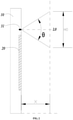
FIG. 3 shows a cross-sectional view of the refrigerator door body in the present invention; -
FIG. 4 shows an assembly diagram of a camera and a mounting base in the present invention; -
FIG. 5 shows an exploded view of the structure shown inFIG. 4 ; -
FIG. 6 shows a cross-sectional view of the mounting base. - The technical solutions in embodiments of the present invention will be clearly and completely described below with reference to the figures in the embodiments of the present invention. Obviously, the described embodiments are only partial embodiments of the present invention, rather than all the embodiments. Based on the embodiments in the present invention, all other embodiments obtained by those having ordinary skill in the art without making any inventive efforts shall fall within the protection scope of the present invention.
- As shown in
FIG. 1 andFIG. 3 , the refrigerator door body in the present invention comprises amain body 10 and acamera 32 mounted on themain body 10 and configured to obtain an image in front of themain body 10. In the present invention, an extension direction of an optical axis L1 of thecamera 32 at the front side of themain body 10 is downwardly inclined relative to a horizontal direction. - The present invention further provides a refrigerator. The refrigerator comprises a cabinet (not shown in the figure) and a refrigerator door body. During specific implementation, the refrigerator door body is hinged to a front side of the cabinet through a hinge. During practical application, the image captured by the
camera 32 is usually a facial image of the user in front of the refrigerator. - Referring to
FIG. 3 , in the present invention, the extension direction of the optical axis L1 of thecamera 32 at the front side of themain body 10 is downwardly inclined relative to the horizontal direction by an angle α, the field-of-view angle of thecamera 31 is θ, and the mounting height of thecamera 31 is h, and the distance between the user and the door body is X. - It may be known from calculation that an upper limit of recognition of the camera 32 a=h+X∗tan(θ/2-α), and a lower limit of recognition of the camera 32 b=h-X∗tan(θ/2+α). It may be further obtained that the recognition range H1 of the
camera 31 is H1=a-b=X∗[tan(θ/2-α)+tan(θ/2+α)]. - Based on the above equation of the recognition range H1 of the
camera 31, it is easier to understand that if α<θ/2<90°, H1 has a minimum value when α=0. That is, when the extension direction of the optical axis L1 of thecamera 32 at the front side of themain body 10 is in a horizontal state (namely, the prior art as shown inFIG. 2 ), the recognition range H1 of thecamera 31 is the smallest. Therefore, it can be seen that the arrangement of thecamera 32 in the present invention can increase the recognition range of thecamera 32, and thus can better adapt to face recognition of users of different heights. - In addition, referring to
FIG. 3 , since the extension direction of the optical axis L1 of thecamera 32 at the front side of themain body 10 is downwardly inclined relative to the horizontal direction, the lower limit b of recognition of thecamera 32 may be made have a smaller value, thereby achieving facial recognition for short users. It may be appreciated that in a specific scenario of application to the refrigerator, thecamera 32 is usually disposed at an upper end of the refrigerator, i.e., h usually has a large value, e.g., the range of h is 1.6m-1.8m. As such, whilst the lower limit b of recognition of thecamera 32 is lowered, recognition of taller users' faces will not be substantially affected. - In the present invention, referring to
FIG. 4 , the refrigerator door body further comprises amounting base 30 provided on themain body 10. Themounting base 30 has a mounting portion for mounting thecamera 32 and defining the extension direction of the optical axis L1 of thecamera 32. - With reference to
FIG. 5 , the mounting portion in the present embodiment is a receivinggroove 300 that receives thecamera 32 and exposes a front surface of thecamera 32, and the receivinggroove 300 is arranged fixedly relative to themain body 10. Specifically, themounting base 300 in the present embodiment has a connectingportion 301 fixed to themain body 10, and the connectingportion 301 is provided with a through hole and fixed to themain body 10 by screws. - In the present embodiment, an inner wall of the receiving
groove 300 has a portion that is in close contact with at least part of an outer wall of thecamera 32 to define the extension direction of the optical axis L1 of thecamera 32. Referring toFIG. 5 , thecamera 32 in the present embodiment is a rectangular parallelepiped, and the inner wall of the receivinggroove 300 has a portion that is in close contact with a back surface and a bottom surface of thecamera 32. As shown inFIG. 6 , the inner wall of the receivinggroove 300 has arear wall 3001 and abottom wall 3002 which are arranged inclined, therear wall 3001 is perpendicular to thebottom wall 3002, and therear wall 3001 and thebottom wall 3002 are in close contact with the back surface and bottom surface of thecamera 32, respectively. In this way, the control of the inclination degree of the extension direction of the optical axis L1 of thecamera 32 may be achieved by adjusting the inclination degree of therear wall 3001 andbottom wall 3002. - In the present embodiment, the
rear wall 3001 of the receivinggroove 300 further has a function of limiting a front-rear position of thecamera 32; thebottom wall 3002 of the receivinggroove 300 further has a function of limiting an up-down position of thecamera 32. - In other embodiments of the present invention, the inner wall of the receiving
groove 300 may also only have a portion in close contact with the back surface of thecamera 32 or only have a portion in close contact with the bottom surface of thecamera 32. Details will not be presented here. - In the specific implementation process, the inner wall of the receiving
groove 300 further has a portion which is in close contact with a left side wall and a right side wall of thecamera 32, and which has a function of limiting a left-right position of thecamera 32. In the present embodiment, therear wall 3001, thebottom wall 3002 and the portion in close contact with the left side wall and the right side wall of thecamera 32 jointly enclose the receivinggroove 300. - It can be appreciated that in other embodiments of the present invention, the shape of the
camera 32 is not limited to a rectangular parallelepiped; correspondingly, the receivinggroove 300 also has an inner wall matching the shape of thecamera 32, which is not described in detail any more here. - In the present embodiment, the
camera 32 is fixed to the inner wall of the receivinggroove 300 in an adhesive manner to achieve the fixation of thecamera 32. In the specific implementation process, glue or double-sided adhesive tape may be used as an adhesive medium. - As a preferred embodiment of the present invention, the angle by which the extension direction of the optical axis L1 of the
camera 32 at the front side of themain body 10 is downwardly inclined relative to the horizontal direction is in a range of 10-20°. - In other unshown embodiments of the present invention, the angle α by which the extension direction of the optical axis L1 of the
camera 32 at the front side of themain body 10 is downwardly inclined relative to the horizontal direction is adjustable. Specifically, thecamera 32 is disposed rotatable relative to themain body 10. As a specific embodiment, the mountingbase 30 comprises a fixed frame (not shown) fixedly connected to themain body 10 and a rotatable frame (not shown) rotatably connected to the fixed frame, the mounting portion of the mountingbase 30 is located on the rotatable frame, and thecamera 32 is fixed to the rotatable frame via the mounting portion. As such, when the rotatable frame rotates, the inclination angle α may be adjusted. In the specific implementation process, the control of the rotation of the rotatable frame may be realized by a mechanism such as a micro motor. - In addition, as shown in
FIG. 1 andFIG. 3 , the door body in the present embodiment further has adisplay panel 20 fixed on the front side of themain body 10, and the mounting height of thecamera 32 is not lower than the mounting height of thedisplay panel 20. The mounting height of thedisplay panel 20 is usually set with reference to the average height of public users, for example, in a range of 1.6-1.8m. - It should be understood that although the description is described according to the embodiments, not every embodiment only includes one independent technical solution, that such a description manner is only for the sake of clarity, that those skilled in the art should take the description as an integral part, and that the technical solutions in the embodiments may be suitably combined to form other embodiments understandable by those skilled in the art.
- The detailed descriptions set forth above are merely specific illustrations of feasible embodiments of the present invention, and are not intended to limit the scope of protection of the present invention. All equivalent embodiments or modifications that do not depart from the art spirit of the present invention should fall within the scope of protection of the present invention.
Claims (10)
- A refrigerator door body, comprising a main body, wherein the refrigerator door body further comprises a camera mounted on the main body and configured to obtain an image in front of the main body, and an extension direction of an optical axis of the camera at the front side of the main body is downwardly inclined relative to a horizontal direction.
- The refrigerator door body according to claim 1, wherein the refrigerator door body further comprises a mounting base provided on the main body, and the mounting base has a mounting portion for mounting the camera and defining the extension direction of the optical axis of the camera.
- The refrigerator door body according to claim 2, wherein the mounting portion is a receiving groove that receives the camera and exposes a front surface of the camera, the receiving groove is fixedly arranged to the main body, and an inner wall of the receiving groove has a portion that is in close contact with at least part of an outer wall of the camera to define the extension direction of the optical axis of the camera.
- The refrigerator door body according to claim 3, wherein the camera is a rectangular parallelepiped, and the inner wall of the receiving groove has a portion that is in close contact with a back surface and/or a bottom surface of the camera.
- The refrigerator door body according to claim 4, wherein the inner wall of the receiving groove further has a portion which is in close contact with a left side wall and a right side wall of the camera.
- The refrigerator door body according to claim 3, wherein the camera is adhered to the inner wall of the receiving groove.
- The refrigerator door body according to claim 2, wherein the mounting base comprises a fixed frame fixedly connected to the main body and a rotatable frame rotatably connected to the fixed frame, and the mounting portion is located on the rotatable frame.
- The refrigerator door body according to any of claims 1-7, wherein an angle by which the extension direction of the optical axis of the camera at the front side of the main body is downwardly inclined relative to the horizontal direction is in a range of 10-20°.
- The refrigerator door body according to any of claims 1-6, wherein the door body further has a display panel fixed on the front side of the main body, and a mounting height of the camera is not lower than the mounting height of the display panel.
- A refrigerator, comprising a cabinet, wherein the refrigerator further comprises the refrigerator door body according to any of claims 1-9.
Applications Claiming Priority (2)
| Application Number | Priority Date | Filing Date | Title |
|---|---|---|---|
| CN201910187404.9A CN111692806A (en) | 2019-03-13 | 2019-03-13 | Refrigerator door body and refrigerator with same |
| PCT/CN2019/105079 WO2020181749A1 (en) | 2019-03-13 | 2019-09-10 | Refrigerator door body and refrigerator having same |
Publications (3)
| Publication Number | Publication Date |
|---|---|
| EP3940322A1 true EP3940322A1 (en) | 2022-01-19 |
| EP3940322A4 EP3940322A4 (en) | 2022-05-04 |
| EP3940322B1 EP3940322B1 (en) | 2026-03-04 |
Family
ID=72426509
Family Applications (1)
| Application Number | Title | Priority Date | Filing Date |
|---|---|---|---|
| EP19919216.2A Active EP3940322B1 (en) | 2019-03-13 | 2019-09-10 | Refrigerator door body and refrigerator having same |
Country Status (3)
| Country | Link |
|---|---|
| EP (1) | EP3940322B1 (en) |
| CN (1) | CN111692806A (en) |
| WO (1) | WO2020181749A1 (en) |
Families Citing this family (3)
| Publication number | Priority date | Publication date | Assignee | Title |
|---|---|---|---|---|
| CN114837508B (en) * | 2019-08-28 | 2023-11-14 | 青岛海尔电冰箱有限公司 | Hinge assembly and refrigeration equipment with same |
| CN113064688A (en) * | 2021-03-26 | 2021-07-02 | 合肥美菱物联科技有限公司 | Control method capable of dynamically changing interface |
| CN113329155A (en) * | 2021-05-27 | 2021-08-31 | 杭州海康威视数字技术股份有限公司 | Shooting equipment and unmanned sales counter |
Family Cites Families (11)
| Publication number | Priority date | Publication date | Assignee | Title |
|---|---|---|---|---|
| JP2002323858A (en) * | 2001-04-24 | 2002-11-08 | Sharp Corp | Home appliances with information display device and device for moving information display device |
| JP2003042626A (en) * | 2001-07-26 | 2003-02-13 | Toshiba Corp | refrigerator |
| KR100613500B1 (en) * | 2004-01-29 | 2006-08-17 | 엘지전자 주식회사 | Camera built-in webpad |
| EP2533534A4 (en) * | 2010-02-01 | 2014-08-13 | Youngkook Electronics Co Ltd | Tracking and monitoring camera device and remote monitoring system using same |
| US9920979B2 (en) * | 2013-10-18 | 2018-03-20 | Lg Electronics Inc. | Refrigerator and control method for the same |
| CN204963414U (en) * | 2015-09-14 | 2016-01-13 | 宁波奇红电器有限公司 | Conveniently observe peripheral condition and ability intelligent control's refrigerator |
| CN106568261B (en) * | 2016-10-19 | 2021-02-26 | 青岛海尔特种电冰箱有限公司 | Method for controlling rotation angle of display screen of refrigerator through preset algorithm and refrigerator |
| KR102327848B1 (en) * | 2017-05-18 | 2021-11-18 | 삼성전자주식회사 | Refrigerator and method of food management thereof |
| CN107270605B (en) * | 2017-06-12 | 2019-12-06 | 青岛海尔特种电冰箱有限公司 | Refrigerator and control method thereof |
| CN107120500A (en) * | 2017-06-14 | 2017-09-01 | 合肥美的智能科技有限公司 | The mounting seat and refrigerator of CCD camera assembly |
| CN207835482U (en) * | 2017-12-07 | 2018-09-07 | 天津艾特麦克斯商务信息咨询有限公司 | An autonomous identification system for smart refrigerators |
-
2019
- 2019-03-13 CN CN201910187404.9A patent/CN111692806A/en active Pending
- 2019-09-10 WO PCT/CN2019/105079 patent/WO2020181749A1/en not_active Ceased
- 2019-09-10 EP EP19919216.2A patent/EP3940322B1/en active Active
Also Published As
| Publication number | Publication date |
|---|---|
| CN111692806A (en) | 2020-09-22 |
| EP3940322A4 (en) | 2022-05-04 |
| EP3940322B1 (en) | 2026-03-04 |
| WO2020181749A1 (en) | 2020-09-17 |
Similar Documents
| Publication | Publication Date | Title |
|---|---|---|
| EP3940322B1 (en) | Refrigerator door body and refrigerator having same | |
| CN111503960B (en) | Refrigerator cap decoration capable of inputting sound | |
| KR102040288B1 (en) | Display apparatus | |
| US4427243A (en) | Display station tilt mechanism | |
| EP4214438B1 (en) | Camera device with an adjustable stand | |
| CN107613057A (en) | Electronic equipment | |
| KR102912430B1 (en) | Prism device, and camera including the same | |
| CN110873497A (en) | Refrigerator with a door | |
| US11649110B2 (en) | Robot | |
| US20230288780A1 (en) | Imaging apparatus | |
| JP7474996B2 (en) | Display device | |
| US20200009721A1 (en) | Robot | |
| CN107635038B (en) | Electronic devices | |
| CN107770311A (en) | Electronic equipment | |
| KR20240073841A (en) | Refrigerator and Controlling Method for the same | |
| US20250130430A1 (en) | Display apparatus | |
| US20250385547A1 (en) | Adjustable Wireless Charging | |
| EP2219071B1 (en) | Focusing device for beam projector | |
| CN109884958A (en) | An intelligent monitoring terminal that can be used in the Internet of Things | |
| CN218413523U (en) | Iris recognition device | |
| KR101662087B1 (en) | Refrigerator and Controlling Method for the same | |
| CN214851518U (en) | Integrated pendulum IRCUT | |
| CN213715584U (en) | Prism driving device | |
| CN210239509U (en) | Electronic access control system and anti-theft door | |
| CN209570831U (en) | A kind of intelligent monitoring terminal can be used for Internet of Things |
Legal Events
| Date | Code | Title | Description |
|---|---|---|---|
| STAA | Information on the status of an ep patent application or granted ep patent |
Free format text: STATUS: THE INTERNATIONAL PUBLICATION HAS BEEN MADE |
|
| PUAI | Public reference made under article 153(3) epc to a published international application that has entered the european phase |
Free format text: ORIGINAL CODE: 0009012 |
|
| STAA | Information on the status of an ep patent application or granted ep patent |
Free format text: STATUS: REQUEST FOR EXAMINATION WAS MADE |
|
| 17P | Request for examination filed |
Effective date: 20210913 |
|
| AK | Designated contracting states |
Kind code of ref document: A1 Designated state(s): AL AT BE BG CH CY CZ DE DK EE ES FI FR GB GR HR HU IE IS IT LI LT LU LV MC MK MT NL NO PL PT RO RS SE SI SK SM TR |
|
| REG | Reference to a national code |
Ref country code: DE Ref legal event code: R079 Free format text: PREVIOUS MAIN CLASS: F25D0023000000 Ipc: F25D0023020000 Ref document number: 602019082216 Country of ref document: DE |
|
| A4 | Supplementary search report drawn up and despatched |
Effective date: 20220331 |
|
| RIC1 | Information provided on ipc code assigned before grant |
Ipc: H04N 5/225 20060101ALN20220325BHEP Ipc: F25D 23/02 20060101AFI20220325BHEP |
|
| DAV | Request for validation of the european patent (deleted) | ||
| DAX | Request for extension of the european patent (deleted) | ||
| STAA | Information on the status of an ep patent application or granted ep patent |
Free format text: STATUS: EXAMINATION IS IN PROGRESS |
|
| 17Q | First examination report despatched |
Effective date: 20240604 |
|
| GRAP | Despatch of communication of intention to grant a patent |
Free format text: ORIGINAL CODE: EPIDOSNIGR1 |
|
| STAA | Information on the status of an ep patent application or granted ep patent |
Free format text: STATUS: GRANT OF PATENT IS INTENDED |
|
| RIC1 | Information provided on ipc code assigned before grant |
Ipc: F25D 23/02 20060101AFI20250905BHEP Ipc: F25D 29/00 20060101ALI20250905BHEP Ipc: H04N 23/55 20230101ALI20250905BHEP Ipc: H04N 23/57 20230101ALI20250905BHEP |
|
| INTG | Intention to grant announced |
Effective date: 20250929 |
|
| GRAS | Grant fee paid |
Free format text: ORIGINAL CODE: EPIDOSNIGR3 |
|
| GRAA | (expected) grant |
Free format text: ORIGINAL CODE: 0009210 |
|
| STAA | Information on the status of an ep patent application or granted ep patent |
Free format text: STATUS: THE PATENT HAS BEEN GRANTED |
|
| RAP3 | Party data changed (applicant data changed or rights of an application transferred) |
Owner name: QINGDAO HAIER REFRIGERATOR CO., LTD. Owner name: HAIER SMART HOME CO., LTD. |
|
| AK | Designated contracting states |
Kind code of ref document: B1 Designated state(s): AL AT BE BG CH CY CZ DE DK EE ES FI FR GB GR HR HU IE IS IT LI LT LU LV MC MK MT NL NO PL PT RO RS SE SI SK SM TR |
|
| REG | Reference to a national code |
Ref country code: CH Ref legal event code: F10 Free format text: ST27 STATUS EVENT CODE: U-0-0-F10-F00 (AS PROVIDED BY THE NATIONAL OFFICE) Effective date: 20260304 Ref country code: GB Ref legal event code: FG4D |
|
| REG | Reference to a national code |
Ref country code: IE Ref legal event code: FG4D |
|
| REG | Reference to a national code |
Ref country code: DE Ref legal event code: R096 Ref document number: 602019082216 Country of ref document: DE |
|
| PG25 | Lapsed in a contracting state [announced via postgrant information from national office to epo] |
Ref country code: RS Free format text: LAPSE BECAUSE OF FAILURE TO SUBMIT A TRANSLATION OF THE DESCRIPTION OR TO PAY THE FEE WITHIN THE PRESCRIBED TIME-LIMIT Effective date: 20260604 |
|
| PG25 | Lapsed in a contracting state [announced via postgrant information from national office to epo] |
Ref country code: ES Free format text: LAPSE BECAUSE OF FAILURE TO SUBMIT A TRANSLATION OF THE DESCRIPTION OR TO PAY THE FEE WITHIN THE PRESCRIBED TIME-LIMIT Effective date: 20260304 |
|
| REG | Reference to a national code |
Ref country code: NL Ref legal event code: MP Effective date: 20260304 |
|
| PG25 | Lapsed in a contracting state [announced via postgrant information from national office to epo] |
Ref country code: PL Free format text: LAPSE BECAUSE OF FAILURE TO SUBMIT A TRANSLATION OF THE DESCRIPTION OR TO PAY THE FEE WITHIN THE PRESCRIBED TIME-LIMIT Effective date: 20260304 |
|
| PG25 | Lapsed in a contracting state [announced via postgrant information from national office to epo] |
Ref country code: GR Free format text: LAPSE BECAUSE OF FAILURE TO SUBMIT A TRANSLATION OF THE DESCRIPTION OR TO PAY THE FEE WITHIN THE PRESCRIBED TIME-LIMIT Effective date: 20260605 |
|
| REG | Reference to a national code |
Ref country code: LT Ref legal event code: MG9D |
|
| PG25 | Lapsed in a contracting state [announced via postgrant information from national office to epo] |
Ref country code: LT Free format text: LAPSE BECAUSE OF FAILURE TO SUBMIT A TRANSLATION OF THE DESCRIPTION OR TO PAY THE FEE WITHIN THE PRESCRIBED TIME-LIMIT Effective date: 20260304 |
|
| PG25 | Lapsed in a contracting state [announced via postgrant information from national office to epo] |
Ref country code: NO Free format text: LAPSE BECAUSE OF FAILURE TO SUBMIT A TRANSLATION OF THE DESCRIPTION OR TO PAY THE FEE WITHIN THE PRESCRIBED TIME-LIMIT Effective date: 20260604 |
|
| PG25 | Lapsed in a contracting state [announced via postgrant information from national office to epo] |
Ref country code: FI Free format text: LAPSE BECAUSE OF FAILURE TO SUBMIT A TRANSLATION OF THE DESCRIPTION OR TO PAY THE FEE WITHIN THE PRESCRIBED TIME-LIMIT Effective date: 20260304 Ref country code: SE Free format text: LAPSE BECAUSE OF FAILURE TO SUBMIT A TRANSLATION OF THE DESCRIPTION OR TO PAY THE FEE WITHIN THE PRESCRIBED TIME-LIMIT Effective date: 20260304 |
|
| PG25 | Lapsed in a contracting state [announced via postgrant information from national office to epo] |
Ref country code: HR Free format text: LAPSE BECAUSE OF FAILURE TO SUBMIT A TRANSLATION OF THE DESCRIPTION OR TO PAY THE FEE WITHIN THE PRESCRIBED TIME-LIMIT Effective date: 20260304 |
|
| PG25 | Lapsed in a contracting state [announced via postgrant information from national office to epo] |
Ref country code: LV Free format text: LAPSE BECAUSE OF FAILURE TO SUBMIT A TRANSLATION OF THE DESCRIPTION OR TO PAY THE FEE WITHIN THE PRESCRIBED TIME-LIMIT Effective date: 20260304 |
|
| PG25 | Lapsed in a contracting state [announced via postgrant information from national office to epo] |
Ref country code: BG Free format text: LAPSE BECAUSE OF FAILURE TO SUBMIT A TRANSLATION OF THE DESCRIPTION OR TO PAY THE FEE WITHIN THE PRESCRIBED TIME-LIMIT Effective date: 20260304 |