EP3940266A1 - Seal ring and sealing structure - Google Patents
Seal ring and sealing structure Download PDFInfo
- Publication number
- EP3940266A1 EP3940266A1 EP20774129.9A EP20774129A EP3940266A1 EP 3940266 A1 EP3940266 A1 EP 3940266A1 EP 20774129 A EP20774129 A EP 20774129A EP 3940266 A1 EP3940266 A1 EP 3940266A1
- Authority
- EP
- European Patent Office
- Prior art keywords
- seal ring
- grooves
- liquid
- inner member
- end portion
- Prior art date
- Legal status (The legal status is an assumption and is not a legal conclusion. Google has not performed a legal analysis and makes no representation as to the accuracy of the status listed.)
- Pending
Links
Images




Classifications
-
- F—MECHANICAL ENGINEERING; LIGHTING; HEATING; WEAPONS; BLASTING
- F16—ENGINEERING ELEMENTS AND UNITS; GENERAL MEASURES FOR PRODUCING AND MAINTAINING EFFECTIVE FUNCTIONING OF MACHINES OR INSTALLATIONS; THERMAL INSULATION IN GENERAL
- F16J—PISTONS; CYLINDERS; SEALINGS
- F16J15/00—Sealings
- F16J15/16—Sealings between relatively-moving surfaces
- F16J15/34—Sealings between relatively-moving surfaces with slip-ring pressed against a more or less radial face on one member
- F16J15/3404—Sealings between relatively-moving surfaces with slip-ring pressed against a more or less radial face on one member and characterised by parts or details relating to lubrication, cooling or venting of the seal
- F16J15/3408—Sealings between relatively-moving surfaces with slip-ring pressed against a more or less radial face on one member and characterised by parts or details relating to lubrication, cooling or venting of the seal at least one ring having an uneven slipping surface
- F16J15/3412—Sealings between relatively-moving surfaces with slip-ring pressed against a more or less radial face on one member and characterised by parts or details relating to lubrication, cooling or venting of the seal at least one ring having an uneven slipping surface with cavities
-
- F—MECHANICAL ENGINEERING; LIGHTING; HEATING; WEAPONS; BLASTING
- F16—ENGINEERING ELEMENTS AND UNITS; GENERAL MEASURES FOR PRODUCING AND MAINTAINING EFFECTIVE FUNCTIONING OF MACHINES OR INSTALLATIONS; THERMAL INSULATION IN GENERAL
- F16J—PISTONS; CYLINDERS; SEALINGS
- F16J15/00—Sealings
- F16J15/16—Sealings between relatively-moving surfaces
- F16J15/18—Sealings between relatively-moving surfaces with stuffing-boxes for elastic or plastic packings
- F16J15/182—Sealings between relatively-moving surfaces with stuffing-boxes for elastic or plastic packings with lubricating, cooling or draining means
-
- F—MECHANICAL ENGINEERING; LIGHTING; HEATING; WEAPONS; BLASTING
- F16—ENGINEERING ELEMENTS AND UNITS; GENERAL MEASURES FOR PRODUCING AND MAINTAINING EFFECTIVE FUNCTIONING OF MACHINES OR INSTALLATIONS; THERMAL INSULATION IN GENERAL
- F16J—PISTONS; CYLINDERS; SEALINGS
- F16J15/00—Sealings
- F16J15/16—Sealings between relatively-moving surfaces
- F16J15/32—Sealings between relatively-moving surfaces with elastic sealings, e.g. O-rings
- F16J15/3244—Sealings between relatively-moving surfaces with elastic sealings, e.g. O-rings with hydrodynamic pumping action
-
- F—MECHANICAL ENGINEERING; LIGHTING; HEATING; WEAPONS; BLASTING
- F16—ENGINEERING ELEMENTS AND UNITS; GENERAL MEASURES FOR PRODUCING AND MAINTAINING EFFECTIVE FUNCTIONING OF MACHINES OR INSTALLATIONS; THERMAL INSULATION IN GENERAL
- F16J—PISTONS; CYLINDERS; SEALINGS
- F16J15/00—Sealings
- F16J15/16—Sealings between relatively-moving surfaces
- F16J15/32—Sealings between relatively-moving surfaces with elastic sealings, e.g. O-rings
- F16J15/3284—Sealings between relatively-moving surfaces with elastic sealings, e.g. O-rings characterised by their structure; Selection of materials
Definitions
- the present invention relates to circular annular seal rings and sealed structures having the circular annular seal rings.
- Annular seal rings are used to seal annular gaps in various machines that have rotating members.
- a seal ring is disposed between a power transmission shaft and a housing in an automotive vehicle to seal lubricating oil inside the housing.
- the present invention provides a seal ring that significantly reduces torque and also reduces an amount of liquid leakage, even when a relative rotational velocity difference of members is large.
- a seal ring according to one aspect of the present invention is a circular annular seal ring made of a resin and disposed between an inner member and an outer member that rotate relative to each other.
- the outer member includes a liquid-storing space in which a liquid is disposed and an inner surface having a circular cross section.
- the inner member is disposed in the liquid-storing space and includes a circumferential groove.
- the seal ring is stationary relative to the inner surface of the outer member, and is slidably disposed in the circumferential groove of the inner member with respect to the inner member to separate the liquid-storing space and an external space. Multiple grooves are formed on an end surface on an external space side of the seal ring.
- Each of the grooves has an end portion that opens at an inner peripheral surface of the seal ring, and extends in a direction opposite to a main rotational direction of the inner member relative to the seal ring from the open end portion. Each of the grooves does not extend in the main rotational direction from the open end portion.
- a sealed structure according to an aspect of the present invention includes the seal ring, the outer member, and the inner member.
- multiple grooves extend in the direction opposite to the main rotational direction of the inner member relative to the seal ring from the open end portions, but do not extend in the main rotational direction from the open end portions.
- the grooves upon rotation of the inner member relative to the seal ring in the main rotational direction, the grooves facilitate discharge of the liquid from the grooves to thin the film of liquid, thereby reducing a shear resistance of the film of liquid, and facilitate vaporization of air in the liquid by cavitation and form a film of air in each of the grooves. Since the air film has a much lower shear resistance than that of the liquid film, the friction between the seal ring and the another member is significantly reduced, resulting in a reduction in the torque.
- the sealed structures including seal rings according to embodiments of the present invention described below are used to seal annular gaps between power transmission shafts (motor output shafts) and housings in electric vehicles or hybrid electric vehicles.
- the sealed structure with the seal ring according to the present invention can be used to seal liquids, such as a lubricating oil and a coolant, in various oil hydraulic machines, water hydraulic machines, and pneumatic machines.
- Such machines include, for example, engines, motors, generators, pumps, compressors, power steering devices in automotive vehicles, speed reducers in automotive vehicles, gearboxes in automotive vehicles, and cooling devices in automotive vehicles.
- the sealed structure 1 includes a housing (outer member) 2, a shaft (inner member) 4, and a seal ring 6.
- the housing 2 is a stationary member and has a lubricating oil space (liquid-storing space) A in which a lubricating oil to be sealed is disposed.
- the shaft 4 is inserted into the lubricating oil space A.
- the shaft 4 is a rotating shaft that rotates about the central axis Ax thereof, and is a power transmission shaft (motor output shaft) of an electric vehicle or a hybrid electric vehicle.
- a circumferential groove 8 is formed on the outer peripheral surface of a portion of the shaft 4, the portion being located inside the inner surface 2A of an end of the lubricating oil space A, and the inner surface 2A having a circular cross section.
- a circular annular seal ring 6 made of a resin is disposed in the circumferential groove 8. The seal ring 6 seals the gap between the shaft 4 and the housing 2 to prevent or reduce leakage of the lubricating oil from the lubricating oil space A inside the housing 2 to an atmosphere space B.
- the radial outer portion of the seal ring 6 protrudes radially outward from the circumferential groove 8, and the outer peripheral surface of the seal ring 6 is in contact with the inner surface 2A.
- the seal ring 6 is fixed to the inner surface 2A of the housing 2.
- “fixed” means that the position of seal ring 6 remains stationary relative to the housing 2, and is not intended to limit whether or not the seal ring 6 is non-removably coupled to housing 2.
- the seal ring 6 is interference fitted into the inner surface 2A.
- the seal ring 6 is fixed to the housing 2 under pressure of the lubricating oil that has entered the inside of the seal ring 6.
- the seal ring 6 is slidably disposed in the circumferential groove 8 of the shaft 4 with respect to the shaft 4 to separate the lubricating oil space A and the external space B and contain the lubricating oil in the lubricating oil space A of the housing 2.
- the housing 2 and the seal ring 6 are fixed, whereas the shaft 4 rotates relative to the housing 2.
- the seal ring 6 has a rectangular cross-section.
- the cross-section of the seal ring 6 is not limited to a rectangular shape.
- the seal ring 6 is formed of a hard resin material that has a small coefficient of friction, such as polyether ether ketone (PEEK), polyphenylene sulfide (PPS), or polytetrafluoroethylene (PTFE).
- PEEK polyether ether ketone
- PPS polyphenylene sulfide
- PTFE polytetrafluoroethylene
- the seal ring 6 is composed of an elongated curved bar that has two ends 6A and 6B. Accordingly, the seal ring 6 can be placed with ease around the shaft 4 such that the seal ring 6 is engaged in the circumferential groove 8 formed on the outer peripheral surface of the shaft 4.
- the two ends 6A and 6B of the seal ring 6 each have two contact portions that allow for circumferential expansion of the seal ring 6 (and thus, radial expansion of the seal ring 6). More specifically, the end 6A has a protruding contact portion 6E and a sliding guide portion 6F, and the other end 6B has a protruding contact portion 6G and a sliding guide portion 6H.
- Each of the protruding contact portions 6E and 6G has a shape such that the radial outer portion thereof extends, and has a space in the radial inner portion.
- Each of the sliding guide portions 6F and 6H has a shape such that the radial outer portion thereof is recessed.
- the radial inner surface (lower surface in Fig. 2 ) of the protruding contact portion 6E on the end 6A is in slidable contact with the radial outer surface (upper surface in Fig. 2 ) of the sliding guide portion 6H on the end 6B
- the radial outer surface (upper surface in Fig. 2 ) of the sliding guide portion 6F on the end 6A is in slidable contact with the radial inner surface (lower surface in Fig. 2 ) of the protruding contact portion 6G on the end 6B.
- the sliding guide portion 6H guides sliding of the protruding contact portion 6E
- the sliding guide portion 6F guides sliding of the protruding contact portion 6G.
- the outer part of seal ring 6 maintains an endless ring shape that is continuous in a circumferential direction as long as the side surface of the protruding contact portion 6E is in contact with the end 6B and the side surface of the protruding contact portion 6G is in contact with the end 6A. Therefore, even if the seal ring 6 is extended in the circumferential direction (and thus, in the radial direction), the sealing ability of the seal ring 6 is not impaired.
- the shape of the ends 6A and 6B shown in Fig. 2 is known and is referred to as a special step-cut.
- the shape of the ends 6A and 6B of the embodiment is only illustrative, and the shape of the ends of the seal ring 6 is not limited to the special step cut, but may be any of a step cut, a straight cut, and a bias cut.
- the seal ring 6 may be an endless ring without the ends 6A and 6B as long as the seal ring 6 can be inserted into the inner surface 2A of the housing 2, and can be engaged in the circumferential groove 8 of the shaft 4.
- the outer peripheral surface of the seal ring 6 is brought into contact with the inner surface 2A of the housing 2. Since the seal ring 6 has an elastic force to radially expand the seal ring 6 itself, the seal ring 6 is brought into close contact with the housing 2. On the other hand, there is a clearance between the inner peripheral surface of the seal ring 6 and the bottom surface 8a of the circumferential groove 8 of the shaft 4, and the lubricating oil in the lubricating oil space A can flow through the clearance. Therefore, the seal ring 6 is firmly fixed to the housing 2 since it is subject to pressure from the lubricating oil that enters the inside of the seal ring 6.
- Multiple grooves 14 are formed on the end surface 12 on the side of the external space B of the seal ring 6.
- FIG. 3 to 6 is a partial rear view of the seal ring 6 showing the end surface 12 of the seal ring 6, and especially showing an example of the grooves 14.
- arrow R indicates a main rotational direction of the shaft 4 (rotational direction mainly used).
- the main rotational direction of the shaft 4 is the rotational direction of a power transmission shaft when the automotive vehicle moves forward in a case in which the shaft 4 is the power transmission shaft of an electric vehicle or a hybrid electric vehicle.
- main rotational direction varies depending on whether the seal ring 6 is placed on the right or left side of the automotive vehicle.
- orientations of the grooves 14 are also opposite to those shown in the drawings.
- the grooves 14 have the same shape and the same size, and are arranged on the end surface 12 at equiangular intervals in the circumferential direction around the central axis Ax.
- the grooves 14 need not necessarily be of the same shape and size.
- the angular intervals of the grooves 14 may be irregular.
- each groove 14 has an inner end portion 14a that is located radially inside and an outer end portion 14b that is located radially outside.
- the inner end portion 14a is open at the inner peripheral surface of the seal ring 6.
- the outer end portion 14b is closed, i.e., surrounded by walls.
- Each groove 14 extends from the open inner end portion 14a in the direction opposite to the main rotational direction of the shaft 4 to the outer end portion 14b, and does not extend in the main rotational direction from the inner end portion 14a.
- the pressure at the inner end portions 14a of the grooves 14 becomes lower than that at the outer end portions 14b, and thus the fluid entering the grooves 14 is discharged from the grooves 14.
- each groove 14 may be any of the shapes shown in Figs. 3 to 6 .
- each groove 14 may have a shape such as a portion of an arc or a portion of a spiral as shown in Fig. 3 or 4 .
- each groove 14 may have a substantially L-shape as shown in Fig. 5 or 6 .
- the shorter portion has the inner end portion 14a, and the longer portion extends from the shorter portion in the direction opposite to the main rotational direction to the outer end portion 14b.
- Fig. 4 shows grooves 14 with a narrow width
- Figs. 3, 5 , and 6 show grooves 14 with a broader width.
- the intervals of the grooves 14 are also not limited.
- Fig. 4 shows grooves 14 with narrow intervals, whereas Figs. 3, 5 , and 6 show grooves 14 with broader intervals.
- the grooves 14 extend from the open inner end portions 14a in a direction opposite to the main rotational direction of the shaft 4 relative to the seal ring 6 so as to generate a film of air, which will be described later, between the seal ring 6 and the shaft 4, and do not extend from the inner end portions 14a in the main rotational direction.
- FIG. 7 to 11 is a cross-sectional view of a seal ring 6 showing an example of a groove 14.
- Each of Figs. 7 to 11 corresponds to a cross-section along VII-VII of Figs. 3 to 6 .
- the groove 14 may have a uniform depth from the inner end portion 14a to the outer end portion 14b.
- the groove 14 may have a depth that gradually (linearly) decreases from the inner end portion 14a to the outer end portion 14b. As shown in Fig. 9 , the groove 14 may have a depth that decreases gradually (in a curved shape) from the inner end portion 14a to the outer end portion 14b. As shown in Fig. 10 , the groove 14 may have a depth that decreases stepwise from the inner end portion 14a to the outer end portion 14b.
- the grooves 14 are formed so as to generate a film of air, which will be described later, between the seal ring 6 and the shaft 4.
- the width of the grooves 14 is, for example, 0.1 mm to several mm, whereas the maximum depth of the grooves 14 is 0.005 mm to 0.05 mm.
- small arrows indicate the flow of fluid in the grooves 14 of the end surface 12 in use of the seal ring 6.
- the large arrow R depicts the main rotational direction of the shaft 4.
- the grooves 14 extend in the direction opposite to the main rotational direction of the shaft 4 relative to the seal ring 6 from the inner end portions 14a, but do not extend in the main rotational direction from the inner end portions 14a.
- the grooves 14 upon rotation of the shaft 4 relative to the seal ring 6 in the main rotational direction R, the grooves 14 facilitate discharge of the lubricating oil from the grooves 14 to thin the film of lubricating oil, as indicated by the small arrows, thereby reducing the shear resistance of the film of lubricating oil, and facilitate vaporization of air in the lubricating oil by cavitation to form a film of air 16 occupying substantially the entire area in each of the grooves 14.
- Air, which forms the air film 16 is also discharged in the direction indicated by the small arrows, but as long as the rotation of the shaft 4 in the main rotational direction R continues, air is generated one after another by cavitation, so that the air film 16 is continuously present in each of the grooves 14. This process can be observed through a transparent plate when, in place of the shaft 4, a transparent plate is pressed against the end surface 12 of the seal ring 6 and rotated.
- the film 16 of air produced as described in this embodiment has a much lower shear resistance than that of the film of lubricating oil, the friction between the seal ring 6 and the wall surface of the circumferential groove 8 on the side of the external space B is considerably reduced, resulting in a reduction in the torque. This effect is particularly remarkable when there is a large difference in the relative rotational velocity of the housing 2 and the shaft 4. Furthermore, since the grooves 14 facilitate discharge of the lubricating oil from the grooves 14 upon rotation of the shaft 4 relative to the seal ring 6 in the main rotational direction R, the amount of leakage of the lubricating oil can be reduced as compared with a case in which the liquid is fed into the grooves.
- the inventors conducted experiments to confirm the above advantageous effect.
- the seal ring 6 according to the embodiment and the seal ring 20 of the comparative example shown in Fig. 12 were used.
- the material of the seal rings 6 and 20 was PEEK.
- each of the grooves 24 is generally T-shaped and has an inner end portion 24a that is located radially inside and two outer end portions 24b and 24c that are located radially outside.
- the inner end portion 24a is open at the inner peripheral surface of the seal ring 6.
- the outer end portions 24b and 24c are closed.
- lubricating oil is discharged from the outer end portion 24b to the inner end portion 24a, and at the same time, an air film is formed from the outer end portion 24b to the inner end portion 24a, but lubricating oil is sent from the inner end portion 24a to the other outer end portion 24c, so that an oil film is formed from the inner end portion 24a to the outer end portion 24c.
- Figs. 13 to 15 The experimental results are shown in Figs. 13 to 15 .
- the round dot corresponds to the embodiment, and the square dot corresponds to the comparative example.
- G ⁇ UB/W
- ⁇ the viscosity of lubricating oil (Pa ⁇ s)
- U the relative velocity between the housing 2 and the shaft 4 (m/s)
- B the contact length of the seal ring and the circumferential groove 8 in the circumferential direction (m)
- W the pressing force acting on the seal ring by the lubricating oil (N).
- Fig. 13 shows a range of dimensionless parameters G in a standard usage environment for electric vehicles (EVs) and hybrid electric vehicles (xHEVs) and a range of dimensionless parameters G in a standard usage environment for automatic transmissions (ATs) and continuously variable transmissions (CVTs).
- EVs electric vehicles
- xHEVs hybrid electric vehicles
- ATs automatic transmissions
- CVTs continuously variable transmissions
- the coefficient of friction ⁇ on the axis of ordinate in Fig. 13 is a coefficient of friction between the seal ring and the wall surface on the side of the external space B of the circumferential groove 8 of the shaft 4.
- the same shaft 4 was used for the seal ring 6 according to the embodiment and for the seal ring 20 of the comparative example.
- the seal ring 20 of the comparative example exhibited a low coefficient of friction.
- the seal rings 20 of the comparative examples in which the lubricating oil is fed into the grooves 14 to facilitate the formation of the oil film, caused a significant increase in frictional resistance.
- the seal ring 6 according to the embodiment in which the air film is formed in the grooves 14 even if the dimensionless parameter G is 1.0 ⁇ 10 -6 or more, the frictional resistance is restrained from increasing.
- the pressure exerted on the seal ring by the lubricating oil was 15 kPa.
- the lubricating oil was an automatic transmission fluid.
- the torque on the axis of ordinate in Fig. 14 is a torque imparted by the seal ring to the wall surface on the side of the external space B of the circumferential groove 8 of the shaft 4.
- the same shaft 4 was used for the seal ring 6 according to the embodiment and the seal ring 20 of the comparative example.
- the seal ring 6 according to the embodiment achieved a remarkable reduction in torque as compared with the seal ring 20 of the comparative example.
- the torque imparted by the seal ring 6 according to the embodiment was approximately 40% of the torque imparted by the seal ring 20 of the comparative example.
- the pressure applied to the seal ring by the lubricating oil was 15 kPa. If the pressure applied to the seal ring is equal to or less than 1 MPa, in the seal ring 20 of the comparative example, which facilitates formation of the oil film by feeding the lubricating oil into the grooves 14, the amount of lubricating oil introduced into the grooves 14 and the sliding surface is likely to be reduced, which results in a significant increase in frictional resistance and thus an increase in torque.
- the amount of leakage on the axis of ordinate in Fig. 15 is the amount of leakage of lubricating oil from the lubricating oil space A to the external space B.
- the seal ring 6 according to the embodiment achieved a remarkable reduction in an amount of leakage as compared with the seal ring 20 of the comparative example.
- the amount of leakage of the lubricating oil by the seal ring 6 according to the embodiment was approximately 20% of the amount of leakage of the lubricating oil by the seal ring 20 of the comparative example.
- the housing 2 and the seal ring 6, which are outer members, are stationary, while the shaft 4, which is the inner member, rotates with respect to the housing 2.
- the seal ring according to the present invention may be disposed between a fixed inner member and a rotating outer member, and may be fixed, e.g., interference fitted to the inner surface of the rotating outer member.
Landscapes
- Engineering & Computer Science (AREA)
- General Engineering & Computer Science (AREA)
- Mechanical Engineering (AREA)
- Physics & Mathematics (AREA)
- Fluid Mechanics (AREA)
- Sealing Devices (AREA)
Abstract
Description
- The present invention relates to circular annular seal rings and sealed structures having the circular annular seal rings.
- Annular seal rings are used to seal annular gaps in various machines that have rotating members. For example, a seal ring is disposed between a power transmission shaft and a housing in an automotive vehicle to seal lubricating oil inside the housing.
- Since the seal ring is interposed between members that rotate relative to each other, the seal ring contributes to an increase in rotational torque of the rotating members. To reduce this torque, a technique has been proposed whereby multiple grooves are formed on an end surface of the seal ring to introduce lubricating oil into the grooves upon rotation of the rotating member, as is disclosed in
Patent Documents 1 to 3. -
- Patent Document 1:
WO 2011/105513 - Patent Document 2:
WO 2011/162283 - Patent Document 3:
Japanese Utility Model Publication 3-88062 - According to the prior art described above, it is expected that introduction of lubricating oil into the grooves of the seal ring will facilitate formation of an oil film between the seal ring and another member to reduce friction between the seal ring and the another member and thereby reduce a torque. However, if the oil film is of excessive thickness, there is a concern that a shear resistance of the oil film will increase and cause an adverse increase in the torque. Furthermore, if an excessive amount of lubricating oil is introduced into the grooves of the seal ring, there is a concern that some of the lubricating oil may leak to an outside space.
- In electric vehicles (EVs) or hybrid electric vehicles (xHEVs), which have become popular in recent years, the rotational velocity of power transmission shafts is significantly higher than that of vehicles powered by internal combustion engines. Use of conventional seal rings in EVs or xHEVs, gives rise to concerns about increase in torque and about leakage of lubricating oil.
- The present invention provides a seal ring that significantly reduces torque and also reduces an amount of liquid leakage, even when a relative rotational velocity difference of members is large.
- A seal ring according to one aspect of the present invention is a circular annular seal ring made of a resin and disposed between an inner member and an outer member that rotate relative to each other. The outer member includes a liquid-storing space in which a liquid is disposed and an inner surface having a circular cross section. The inner member is disposed in the liquid-storing space and includes a circumferential groove. The seal ring is stationary relative to the inner surface of the outer member, and is slidably disposed in the circumferential groove of the inner member with respect to the inner member to separate the liquid-storing space and an external space. Multiple grooves are formed on an end surface on an external space side of the seal ring. Each of the grooves has an end portion that opens at an inner peripheral surface of the seal ring, and extends in a direction opposite to a main rotational direction of the inner member relative to the seal ring from the open end portion. Each of the grooves does not extend in the main rotational direction from the open end portion.
- A sealed structure according to an aspect of the present invention includes the seal ring, the outer member, and the inner member.
- In the present invention, multiple grooves extend in the direction opposite to the main rotational direction of the inner member relative to the seal ring from the open end portions, but do not extend in the main rotational direction from the open end portions. Thus, upon rotation of the inner member relative to the seal ring in the main rotational direction, the grooves facilitate discharge of the liquid from the grooves to thin the film of liquid, thereby reducing a shear resistance of the film of liquid, and facilitate vaporization of air in the liquid by cavitation and form a film of air in each of the grooves. Since the air film has a much lower shear resistance than that of the liquid film, the friction between the seal ring and the another member is significantly reduced, resulting in a reduction in the torque. This effect is particularly remarkable when there is a large difference in the relative rotational velocity of the members. In addition, since the grooves facilitate discharge of the liquid from the groove upon rotation of the inner member relative to the seal ring in the main rotational direction, an amount of leakage of the liquid can be reduced as compared with a case in which the liquid is fed into the grooves.
-
-
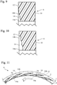
Fig. 1 is a cross-sectional view showing a sealed structure including a seal ring according to an embodiment of the present invention; -
Fig. 2 is a front view of the seal ring according to the embodiment; -
Fig. 3 is a partial rear view showing the seal ring according to the embodiment, especially an example of grooves; -
Fig. 4 is a partial rear view showing the seal ring according to the embodiment, especially another example of grooves; -
Fig. 5 is a partial rear view showing the seal ring according to the embodiment, especially another example of grooves; -
Fig. 6 is a partial rear view showing the seal ring according to the embodiment, especially another example of grooves; -
Fig. 7 is a cross-sectional view showing the seal ring according to the embodiment, especially an example of grooves; -
Fig. 8 is a cross-sectional view showing the seal ring according to the embodiment, especially another example of grooves; -
Fig. 9 is a cross-sectional view showing the seal ring according to the embodiment, especially another example of grooves; -
Fig. 10 is a cross-sectional view showing the seal ring according to the embodiment, especially another example of grooves; -
Fig. 11 is a view illustrating fluid flow within the grooves in use of the seal ring according to the embodiment; -
Fig. 12 is a partial rear view showing a seal ring according to a comparative example, especially an example of grooves; -
Fig. 13 is a graph showing a relationship between the coefficient of friction and a dimensionless parameter with regard to the embodiment and the comparative example; -
Fig. 14 is a graph showing a relationship between the torque and the relative velocity of the shaft and the housing with regard to the embodiment and the comparative example; and -
Fig. 15 is a graph showing a relationship between the leakage amount of lubricating oil and the relative velocity of the shaft and the housing with regard to the embodiment and the comparative example. - Hereinafter, with reference to the accompanying drawings, various embodiments according to the present invention will be described. It is of note that the drawings are not necessarily to scale, and certain features may be exaggerated or omitted.
- The sealed structures including seal rings according to embodiments of the present invention described below are used to seal annular gaps between power transmission shafts (motor output shafts) and housings in electric vehicles or hybrid electric vehicles. However, the following description is only illustrative, and the sealed structure with the seal ring according to the present invention can be used to seal liquids, such as a lubricating oil and a coolant, in various oil hydraulic machines, water hydraulic machines, and pneumatic machines. Such machines include, for example, engines, motors, generators, pumps, compressors, power steering devices in automotive vehicles, speed reducers in automotive vehicles, gearboxes in automotive vehicles, and cooling devices in automotive vehicles.
- As shown in
Fig. 1 , the sealedstructure 1 includes a housing (outer member) 2, a shaft (inner member) 4, and aseal ring 6. Thehousing 2 is a stationary member and has a lubricating oil space (liquid-storing space) A in which a lubricating oil to be sealed is disposed. Theshaft 4 is inserted into the lubricating oil space A. Theshaft 4 is a rotating shaft that rotates about the central axis Ax thereof, and is a power transmission shaft (motor output shaft) of an electric vehicle or a hybrid electric vehicle. - A
circumferential groove 8 is formed on the outer peripheral surface of a portion of theshaft 4, the portion being located inside theinner surface 2A of an end of the lubricating oil space A, and theinner surface 2A having a circular cross section. A circularannular seal ring 6 made of a resin is disposed in thecircumferential groove 8. Theseal ring 6 seals the gap between theshaft 4 and thehousing 2 to prevent or reduce leakage of the lubricating oil from the lubricating oil space A inside thehousing 2 to an atmosphere space B. - The radial outer portion of the
seal ring 6 protrudes radially outward from thecircumferential groove 8, and the outer peripheral surface of theseal ring 6 is in contact with theinner surface 2A. Theseal ring 6 is fixed to theinner surface 2A of thehousing 2. Here, "fixed" means that the position ofseal ring 6 remains stationary relative to thehousing 2, and is not intended to limit whether or not theseal ring 6 is non-removably coupled tohousing 2. In this embodiment, theseal ring 6 is interference fitted into theinner surface 2A. Furthermore, as will be described later, theseal ring 6 is fixed to thehousing 2 under pressure of the lubricating oil that has entered the inside of theseal ring 6. - The
seal ring 6 is slidably disposed in thecircumferential groove 8 of theshaft 4 with respect to theshaft 4 to separate the lubricating oil space A and the external space B and contain the lubricating oil in the lubricating oil space A of thehousing 2. In the sealedstructure 1, thehousing 2 and theseal ring 6 are fixed, whereas theshaft 4 rotates relative to thehousing 2. - In this embodiment, the
seal ring 6 has a rectangular cross-section. However, the cross-section of theseal ring 6 is not limited to a rectangular shape. - The
seal ring 6 is formed of a hard resin material that has a small coefficient of friction, such as polyether ether ketone (PEEK), polyphenylene sulfide (PPS), or polytetrafluoroethylene (PTFE). - As shown in
Fig. 2 , theseal ring 6 is composed of an elongated curved bar that has twoends seal ring 6 can be placed with ease around theshaft 4 such that theseal ring 6 is engaged in thecircumferential groove 8 formed on the outer peripheral surface of theshaft 4. - The two ends 6A and 6B of the
seal ring 6 each have two contact portions that allow for circumferential expansion of the seal ring 6 (and thus, radial expansion of the seal ring 6). More specifically, theend 6A has aprotruding contact portion 6E and a sliding guide portion 6F, and theother end 6B has a protruding contact portion 6G and a slidingguide portion 6H. Each of the protrudingcontact portions 6E and 6G has a shape such that the radial outer portion thereof extends, and has a space in the radial inner portion. Each of the slidingguide portions 6F and 6H has a shape such that the radial outer portion thereof is recessed. - When the two ends 6A and 6B are butted, the radial inner surface (lower surface in
Fig. 2 ) of the protrudingcontact portion 6E on theend 6A is in slidable contact with the radial outer surface (upper surface inFig. 2 ) of the slidingguide portion 6H on theend 6B, and the radial outer surface (upper surface inFig. 2 ) of the sliding guide portion 6F on theend 6A is in slidable contact with the radial inner surface (lower surface inFig. 2 ) of the protruding contact portion 6G on theend 6B. Thus, the slidingguide portion 6H guides sliding of the protrudingcontact portion 6E, and the sliding guide portion 6F guides sliding of the protruding contact portion 6G. - Even though the
ends seal ring 6 maintains an endless ring shape that is continuous in a circumferential direction as long as the side surface of the protrudingcontact portion 6E is in contact with theend 6B and the side surface of the protruding contact portion 6G is in contact with theend 6A. Therefore, even if theseal ring 6 is extended in the circumferential direction (and thus, in the radial direction), the sealing ability of theseal ring 6 is not impaired. - The shape of the
ends Fig. 2 is known and is referred to as a special step-cut. The shape of theends seal ring 6 is not limited to the special step cut, but may be any of a step cut, a straight cut, and a bias cut. Alternatively, theseal ring 6 may be an endless ring without theends seal ring 6 can be inserted into theinner surface 2A of thehousing 2, and can be engaged in thecircumferential groove 8 of theshaft 4. - Referring to
Fig. 1 , as described above, the outer peripheral surface of theseal ring 6 is brought into contact with theinner surface 2A of thehousing 2. Since theseal ring 6 has an elastic force to radially expand theseal ring 6 itself, theseal ring 6 is brought into close contact with thehousing 2. On the other hand, there is a clearance between the inner peripheral surface of theseal ring 6 and thebottom surface 8a of thecircumferential groove 8 of theshaft 4, and the lubricating oil in the lubricating oil space A can flow through the clearance. Therefore, theseal ring 6 is firmly fixed to thehousing 2 since it is subject to pressure from the lubricating oil that enters the inside of theseal ring 6. - At the
end surface 10 on the side of the lubricating oil space A of theseal ring 6, hydraulic pressure of the lubricating oil in the lubricating oil space A is exerted as depicted by an arrow, so that theseal ring 6 is pushed toward the side of the external space B. Therefore, theend surface 12 on the side of the external space B of theseal ring 6 is pressed against the wall surface on the side of the external space B of thecircumferential groove 8 of theshaft 4. However, the lubricating oil penetrates a small gap between theend surface 12 and the wall surface on the side of the external space B of thecircumferential groove 8. Thus, precisely stated, theend surface 12 is not in surface contact with the wall surface on the side of the external space B of thecircumferential groove 8, and a film of oil (and a film of air that will be described later) is interposed therebetween. -
Multiple grooves 14 are formed on theend surface 12 on the side of the external space B of theseal ring 6. - Each of
Figs. 3 to 6 is a partial rear view of theseal ring 6 showing theend surface 12 of theseal ring 6, and especially showing an example of thegrooves 14. InFigs. 3 to 6 , arrow R indicates a main rotational direction of the shaft 4 (rotational direction mainly used). The main rotational direction of theshaft 4 is the rotational direction of a power transmission shaft when the automotive vehicle moves forward in a case in which theshaft 4 is the power transmission shaft of an electric vehicle or a hybrid electric vehicle. - It is of note that the main rotational direction varies depending on whether the
seal ring 6 is placed on the right or left side of the automotive vehicle. When the main rotational direction is opposite to that shown in the drawings, orientations of thegrooves 14 are also opposite to those shown in the drawings. - Preferably, the
grooves 14 have the same shape and the same size, and are arranged on theend surface 12 at equiangular intervals in the circumferential direction around the central axis Ax. However, thegrooves 14 need not necessarily be of the same shape and size. The angular intervals of thegrooves 14 may be irregular. - As shown in
Figs. 3-6 , eachgroove 14 has aninner end portion 14a that is located radially inside and anouter end portion 14b that is located radially outside. Theinner end portion 14a is open at the inner peripheral surface of theseal ring 6. Theouter end portion 14b is closed, i.e., surrounded by walls. - Each
groove 14 extends from the openinner end portion 14a in the direction opposite to the main rotational direction of theshaft 4 to theouter end portion 14b, and does not extend in the main rotational direction from theinner end portion 14a. Thus, upon the rotation of theshaft 4, the pressure at theinner end portions 14a of thegrooves 14 becomes lower than that at theouter end portions 14b, and thus the fluid entering thegrooves 14 is discharged from thegrooves 14. - The
grooves 14 may be any of the shapes shown inFigs. 3 to 6 . In other words, eachgroove 14 may have a shape such as a portion of an arc or a portion of a spiral as shown inFig. 3 or 4 . Alternatively, eachgroove 14 may have a substantially L-shape as shown inFig. 5 or6 . In the substantially L-shape inFigs. 5 and6 , the shorter portion has theinner end portion 14a, and the longer portion extends from the shorter portion in the direction opposite to the main rotational direction to theouter end portion 14b. - The length and width of
grooves 14 are not limited.Fig. 4 showsgrooves 14 with a narrow width, whereasFigs. 3, 5 , and6 show grooves 14 with a broader width. - The intervals of the
grooves 14 are also not limited.Fig. 4 showsgrooves 14 with narrow intervals, whereasFigs. 3, 5 , and6 show grooves 14 with broader intervals. - Other variations in the lengths, widths, and intervals of the
grooves 14 are envisaged. In any case, thegrooves 14 extend from the openinner end portions 14a in a direction opposite to the main rotational direction of theshaft 4 relative to theseal ring 6 so as to generate a film of air, which will be described later, between theseal ring 6 and theshaft 4, and do not extend from theinner end portions 14a in the main rotational direction. - Each of
Figs. 7 to 11 is a cross-sectional view of aseal ring 6 showing an example of agroove 14. Each ofFigs. 7 to 11 corresponds to a cross-section along VII-VII ofFigs. 3 to 6 . - As shown in
Fig. 7 , thegroove 14 may have a uniform depth from theinner end portion 14a to theouter end portion 14b. - As shown in
Fig. 8 , thegroove 14 may have a depth that gradually (linearly) decreases from theinner end portion 14a to theouter end portion 14b. As shown inFig. 9 , thegroove 14 may have a depth that decreases gradually (in a curved shape) from theinner end portion 14a to theouter end portion 14b. As shown inFig. 10 , thegroove 14 may have a depth that decreases stepwise from theinner end portion 14a to theouter end portion 14b. - Other variations of the depth of the
grooves 14 are envisaged. In any case, thegrooves 14 are formed so as to generate a film of air, which will be described later, between theseal ring 6 and theshaft 4. The width of thegrooves 14 is, for example, 0.1 mm to several mm, whereas the maximum depth of thegrooves 14 is 0.005 mm to 0.05 mm. - In
Fig. 11 , small arrows indicate the flow of fluid in thegrooves 14 of theend surface 12 in use of theseal ring 6. In the same manner as inFigs.3 to 6 , the large arrow R depicts the main rotational direction of theshaft 4. As described above, whereas theseal ring 6 is stationary, lubricating oil in contact with theend surface 12 of theseal ring 6 rotates in the same direction as theshaft 4. - In this embodiment, the
grooves 14 extend in the direction opposite to the main rotational direction of theshaft 4 relative to theseal ring 6 from theinner end portions 14a, but do not extend in the main rotational direction from theinner end portions 14a. Thus, upon rotation of theshaft 4 relative to theseal ring 6 in the main rotational direction R, thegrooves 14 facilitate discharge of the lubricating oil from thegrooves 14 to thin the film of lubricating oil, as indicated by the small arrows, thereby reducing the shear resistance of the film of lubricating oil, and facilitate vaporization of air in the lubricating oil by cavitation to form a film ofair 16 occupying substantially the entire area in each of thegrooves 14. Air, which forms theair film 16, is also discharged in the direction indicated by the small arrows, but as long as the rotation of theshaft 4 in the main rotational direction R continues, air is generated one after another by cavitation, so that theair film 16 is continuously present in each of thegrooves 14. This process can be observed through a transparent plate when, in place of theshaft 4, a transparent plate is pressed against theend surface 12 of theseal ring 6 and rotated. - Therefore, during rotation in the main rotational direction R of the
shaft 4, not only the oil film, but also theair film 16 continues to be sandwiched between theend surface 12 of theseal ring 6 and the wall surface on the side of the external space B of thecircumferential groove 8 of theshaft 4. Generally, a large amount of air is dissolved in lubricating oil, and as a result cavitation is likely to occur. From another point of view, an amount of energy exerted by bubbles vaporized by cavitation from lubricating oil is small compared to that exerted by water flow, and thus theseal ring 6 and theshaft 4 are less likely to be damaged by the bubbles. - On the other hand, according to the prior art disclosed in
Patent Documents 1 to 3, it is expected that introduction of lubricating oil into grooves of a seal ring will facilitate formation of an oil film between the seal ring and another member to reduce friction between the seal ring and the another member and thereby lower a torque. However, if the oil film is of excessive thickness there is a concern that a shear resistance of the oil film will increase and cause an adverse increase in the torque. Furthermore, if an excessive amount of lubricating oil is introduced into the grooves of the seal ring, there is a concern that some of the lubricating oil may leak to an outside space. - Since the
film 16 of air produced as described in this embodiment has a much lower shear resistance than that of the film of lubricating oil, the friction between theseal ring 6 and the wall surface of thecircumferential groove 8 on the side of the external space B is considerably reduced, resulting in a reduction in the torque. This effect is particularly remarkable when there is a large difference in the relative rotational velocity of thehousing 2 and theshaft 4. Furthermore, since thegrooves 14 facilitate discharge of the lubricating oil from thegrooves 14 upon rotation of theshaft 4 relative to theseal ring 6 in the main rotational direction R, the amount of leakage of the lubricating oil can be reduced as compared with a case in which the liquid is fed into the grooves. - The inventors conducted experiments to confirm the above advantageous effect. In the experiments, the
seal ring 6 according to the embodiment and theseal ring 20 of the comparative example shown inFig. 12 were used. The material of the seal rings 6 and 20 was PEEK. - According to the comparative example,
multiple grooves 24 are formed on theend surface 12 on the side of the external space B of theseal ring 20. Each of thegrooves 24 is generally T-shaped and has aninner end portion 24a that is located radially inside and twoouter end portions inner end portion 24a is open at the inner peripheral surface of theseal ring 6. Theouter end portions - In the
seal ring 20 according to the comparative example, upon the rotation in the main rotational direction R of theshaft 4 relative to theseal ring 6, lubricating oil is discharged from theouter end portion 24b to theinner end portion 24a, and at the same time, an air film is formed from theouter end portion 24b to theinner end portion 24a, but lubricating oil is sent from theinner end portion 24a to the otherouter end portion 24c, so that an oil film is formed from theinner end portion 24a to theouter end portion 24c. - The experimental results are shown in
Figs. 13 to 15 . InFigs. 13 to 15 , the round dot corresponds to the embodiment, and the square dot corresponds to the comparative example. - The dimensionless parameter G axis of abscissas in
Fig. 13 was calculated from the following equation.
housing 2 and the shaft 4 (m/s), B is the contact length of the seal ring and thecircumferential groove 8 in the circumferential direction (m), and W is the pressing force acting on the seal ring by the lubricating oil (N). -
Fig. 13 shows a range of dimensionless parameters G in a standard usage environment for electric vehicles (EVs) and hybrid electric vehicles (xHEVs) and a range of dimensionless parameters G in a standard usage environment for automatic transmissions (ATs) and continuously variable transmissions (CVTs). - The coefficient of friction µ on the axis of ordinate in
Fig. 13 is a coefficient of friction between the seal ring and the wall surface on the side of the external space B of thecircumferential groove 8 of theshaft 4. In the experiments, thesame shaft 4 was used for theseal ring 6 according to the embodiment and for theseal ring 20 of the comparative example. - As will be apparent from
Fig. 13 , in the standard use environment for the automatic transmission and the continuously variable transmission, theseal ring 20 of the comparative example exhibited a low coefficient of friction. However, in a case in which the dimensionless parameter G is 1.0 × 10⁻⁶ or more, which is usual in the standard use environments for electric vehicles and hybrid electric vehicles, the seal rings 20 of the comparative examples, in which the lubricating oil is fed into thegrooves 14 to facilitate the formation of the oil film, caused a significant increase in frictional resistance. On the other hand, in theseal ring 6 according to the embodiment in which the air film is formed in thegrooves 14, even if the dimensionless parameter G is 1.0 × 10⁻⁶ or more, the frictional resistance is restrained from increasing. - In the experiments shown in
Figs. 14 and 15 , the pressure exerted on the seal ring by the lubricating oil was 15 kPa. The lubricating oil was an automatic transmission fluid. - The torque on the axis of ordinate in
Fig. 14 is a torque imparted by the seal ring to the wall surface on the side of the external space B of thecircumferential groove 8 of theshaft 4. In the experiments, thesame shaft 4 was used for theseal ring 6 according to the embodiment and theseal ring 20 of the comparative example. - As will be apparent from
Fig. 14 , theseal ring 6 according to the embodiment achieved a remarkable reduction in torque as compared with theseal ring 20 of the comparative example. The torque imparted by theseal ring 6 according to the embodiment was approximately 40% of the torque imparted by theseal ring 20 of the comparative example. - In the experiment of
Fig. 14 , the pressure applied to the seal ring by the lubricating oil was 15 kPa. If the pressure applied to the seal ring is equal to or less than 1 MPa, in theseal ring 20 of the comparative example, which facilitates formation of the oil film by feeding the lubricating oil into thegrooves 14, the amount of lubricating oil introduced into thegrooves 14 and the sliding surface is likely to be reduced, which results in a significant increase in frictional resistance and thus an increase in torque. In contrast, in theseal ring 6 according to the embodiment, which forms a film of air in each of thegrooves 14, even if the pressure applied to theseal ring 6 is equal to or less than 1 MPa, a film of air is formed in eachgroove 14, and the oil film is thinned, thereby restraining an increase in frictional resistance and an increase in torque. - The amount of leakage on the axis of ordinate in
Fig. 15 is the amount of leakage of lubricating oil from the lubricating oil space A to the external space B. - As will be apparent from
Fig. 15 , theseal ring 6 according to the embodiment achieved a remarkable reduction in an amount of leakage as compared with theseal ring 20 of the comparative example. The amount of leakage of the lubricating oil by theseal ring 6 according to the embodiment was approximately 20% of the amount of leakage of the lubricating oil by theseal ring 20 of the comparative example. - The following is understood from the result of
Fig. 15 . If the difference in velocity of theshaft 4 relative to the seal ring is equal to or greater than 3 m/s, in theseal ring 20 of the comparative example, which facilitates formation of the oil film by feeding lubricating oil into thegrooves 14, a significant increase in frictional resistance and thus an increase in torque is likely to result. In contrast, in theseal ring 6 according to the embodiment, which forms a film of air in each of thegrooves 14, even when the difference in velocity of theshaft 4 relative to theseal ring 6 is 3m/s or more, an increase in frictional resistance, and thus an increase in torque are restricted. - The present invention has been shown and described with reference to preferred embodiments thereof. However, it will be understood by those skilled in the art that various changes in form and detail may be made without departing from the scope of the invention as defined by the claims. Such variations, alterations, and modifications are intended to be encompassed in the scope of the present invention.
- For example, in the above embodiment, the
housing 2 and theseal ring 6, which are outer members, are stationary, while theshaft 4, which is the inner member, rotates with respect to thehousing 2. However, the seal ring according to the present invention may be disposed between a fixed inner member and a rotating outer member, and may be fixed, e.g., interference fitted to the inner surface of the rotating outer member. - Aspects of the present invention are also set out in the following numbered clauses:
-
Clause 1. A circular annular seal ring made of a resin and disposed between an inner member and an outer member that rotate relative to each other,- the outer member comprising a liquid-storing space in which a liquid is disposed and an inner surface having a circular cross section,
- the inner member being disposed in the liquid-storing space and comprising a circumferential groove,
- the seal ring being stationary relative to the inner surface of the outer member and being slidably disposed in the circumferential groove of the inner member with respect to the inner member to separate the liquid-storing space and an external space,
- multiple grooves being formed on an end surface on an external space side of the seal ring,
- each of the grooves comprising an end portion that opens at an inner peripheral surface of the seal ring, each of the grooves extending in a direction opposite to a main rotational direction of the inner member relative to the seal ring from the open end portion, each of the grooves not extending in the main rotational direction from the open end portion.
In this aspect, multiple grooves extend in the direction opposite to the main rotational direction of the inner member relative to the seal ring from the open end portions, but do not extend in the main rotational direction from the open end portions. Thus, upon rotation of the inner member relative to the seal ring in the main rotational direction, the grooves facilitate discharge of the liquid from the grooves and facilitate vaporization of air in the liquid by cavitation to form a film of air in each of the grooves. Since the air film has a much lower shear resistance than that of the liquid film, the friction between the seal ring and another member is significantly reduced, resulting in a reduction in the torque. This effect is particularly remarkable when the relative rotational velocity difference of the members is large. In addition, since the grooves facilitate discharge of the liquid from the grooves upon the rotation of the inner member relative to the seal ring in the main rotational direction, an amount of leakage of the liquid can be reduced as compared with a case in which the liquid is fed into the grooves. -
Clause 2. The seal ring according toclause 1, wherein the multiple grooves are configured to facilitate discharge of the liquid from the multiple grooves upon rotation of the inner member relative to the seal ring in the main rotational direction, and to facilitate vaporization of air in the liquid by cavitation to form a film of air in each of the grooves. - Clause 3. The seal ring according to
clause
In a case in which the dimensionless parameter G is 1.0 × 10⁻⁶ or more, a seal ring that feeds liquid into the grooves and facilitates formation of the liquid film is likely to cause a remarkable increase in frictional resistance, and thus an increase in torque. On the other hand, in this aspect, in which the film of air is formed in each of the grooves, even if the dimensionless parameter G is 1.0 × 10⁻⁶ or more, the increase in frictional resistance is restricted, and the increase in torque is also restricted. -
Clause 4. The seal ring according to any one of clauses 1-3, wherein the seal ring is used in a use environment that includes at least a condition in which a relative velocity difference of the inner member and the seal ring is equal to or greater than 3 m/s.
If the relative velocity difference of the inner member and the seal ring is equal to or greater than 3 m/s, a seal ring that feeds liquid into the grooves and facilitates formation of the liquid film is likely to cause a significant increase in frictional resistance, and thus an increase in torque. In contrast, in this aspect, in which the film of air is formed in each of the grooves, even if the relative velocity difference of the inner member and the seal ring is 3 m/s or more, the increase in frictional resistance is restricted, and the increase in torque is also restricted. - Clause 5. The seal ring according to any one of clauses 1-4, wherein the seal ring is used in a use environment that includes at least a condition in which a pressure exerted on the seal ring is equal to or less than 1 MPa.
In a case in which the pressure applied to the seal ring is equal to or less than 1 MPa, in a seal ring that feeds liquid into the grooves and facilitates formation of the liquid film, the amount of liquid introduced into the grooves and the sliding surface is reduced, and thus the frictional resistance may greatly increase, and the torque is also likely to increase. On the other hand, in this aspect, in which the film of air is formed in each of the grooves, even if the pressure applied to the seal ring is equal to or less than 1 MPa, the film of air is formed in each of the grooves and the liquid film becomes thin, so that the increase in frictional resistance is restricted, and the increase in torque is also restricted. -
Clause 6. A sealed structure comprising:- an outer member comprising a liquid-storing space in which a liquid is disposed and an inner surface having a circular cross section;
- an inner member rotating relative to the outer member and being disposed in the liquid-storing space and comprising a circumferential groove; and
- a circular annular seal ring made of a resin and disposed between the inner member and the outer member,
- the seal ring being stationary relative to the inner surface of the outer member and being slidably disposed in the circumferential groove of the inner member with respect to the inner member to separate the liquid-storing space and an external space,
- an end surface on an external space side of the seal ring comprising multiple grooves,
- each of the grooves comprising an end portion that opens at an inner peripheral surface of the seal ring, each of the grooves extending in a direction opposite to a main rotational direction of the inner member relative to the seal ring from the open end portion, each of the grooves not extending in the main rotational direction from the open end portion.
- Clause 7. The sealed structure according to
clause 6, wherein the multiple grooves are configured to facilitate discharge of the liquid from the multiple grooves upon rotation of the inner member relative to the seal ring in the main rotational direction, and to facilitate vaporization of air in the liquid by cavitation to form a film of air in each of the grooves. -
Clause 8. The sealed structure according toclause 6 or 7, wherein the seal ring is used in a use environment that includes at least a condition in which a dimensionless parameter G is equal to or greater than 1.0 × 10⁻⁶. -
Clause 9. The sealed structure according to any one of clauses 6-8, wherein the seal ring is used in a use environment that includes at least a condition in which a relative velocity difference of the inner member and the seal ring is equal to or greater than 3 m/s. -
Clause 10. The sealed structure according to any one of clauses 6-9, wherein the seal ring is used in a use environment that includes at least a condition in which a pressure exerted on the seal ring is equal to or less than 1 MPa. -
- A:
- Lubricating oil space (liquid-storing space)
- B:
- External space
- R:
- Main rotational direction of shaft
- 1:
- Sealed structure
- 2:
- Housing (Outer Member)
- 2A:
- Inner surface
- 4:
- Shaft (inner member)
- 6:
- Seal ring
- 8:
- Circumferential groove
- 8a:
- Bottom surface
- 10:
- End surface
- 12:
- End surface
- 14:
- Groove
- 14a:
- Inner end portion
- 14b:
- Outer end portion
- 16:
- Air film
Claims (10)
- A circular annular seal ring made of a resin and disposed between an inner member and an outer member that rotate relative to each other,the outer member comprising a liquid-storing space in which a liquid is disposed and an inner surface having a circular cross section,the inner member being disposed in the liquid-storing space and comprising a circumferential groove,the seal ring being stationary relative to the inner surface of the outer member and being slidably disposed in the circumferential groove of the inner member with respect to the inner member to separate the liquid-storing space and an external space,an end surface on an external space side of the seal ring comprising multiple grooves,each of the grooves comprising an end portion that opens at an inner peripheral surface of the seal ring, each of the grooves extending in a direction opposite to a main rotational direction of the inner member relative to the seal ring from the open end portion, each of the grooves not extending in the main rotational direction from the open end portion.
- The seal ring according to claim 1, wherein the multiple grooves are configured to facilitate discharge of the liquid from the multiple grooves upon rotation of the inner member relative to the seal ring in the main rotational direction, and to facilitate vaporization of air in the liquid by cavitation to form a film of air in each of the grooves.
- The seal ring according to claim 1 or 2, wherein the seal ring is used in a use environment that includes at least a condition in which a dimensionless parameter G is equal to or greater than 1.0 × 10⁻⁶.
- The seal ring according to any one of claims 1-3, wherein the seal ring is used in a use environment that includes at least a condition in which a relative velocity difference of the inner member and the seal ring is equal to or greater than 3 m/s.
- The seal ring according to any one of claims 1-4, wherein the seal ring is used in a use environment that includes at least a condition in which a pressure exerted on the seal ring is equal to or less than 1 MPa.
- A sealed structure comprising:an outer member comprising a liquid-storing space in which a liquid is disposed and an inner surface having a circular cross section;an inner member rotating relative to the outer member and being disposed in the liquid-storing space and comprising a circumferential groove; anda circular annular seal ring made of a resin and disposed between the inner member and the outer member,the seal ring being stationary relative to the inner surface of the outer member and being slidably disposed in the circumferential groove of the inner member with respect to the inner member to separate the liquid-storing space and an external space,an end surface on an external space side of the seal ring comprising multiple grooves,each of the grooves comprising an end portion that opens at an inner peripheral surface of the seal ring, each of the grooves extending in a direction opposite to a main rotational direction of the inner member relative to the seal ring from the open end portion, each of the grooves not extending in the main rotational direction from the open end portion.
- The sealed structure according to claim 6, wherein the multiple grooves are configured to facilitate discharge of the liquid from the multiple grooves upon rotation of the inner member relative to the seal ring in the main rotational direction, and to facilitate vaporization of air in the liquid by cavitation to form a film of air in each of the grooves.
- The sealed structure according to claim 6 or 7, wherein the sealed structure is used in a use environment that includes at least a condition in which a dimensionless parameter G is equal to or greater than 1.0 × 10⁻⁶.
- The sealed structure according to any one of claims 6-8, wherein the sealed structure is used in a use environment that includes at least a condition in which a relative velocity difference of the inner member and the seal ring is equal to or greater than 3 m/s.
- The sealed structure according to any one of claims 6-9, wherein the sealed structure is used in a use environment that includes at least a condition in which a pressure exerted on the seal ring is equal to or less than 1 MPa.
Applications Claiming Priority (2)
| Application Number | Priority Date | Filing Date | Title |
|---|---|---|---|
| JP2019048739 | 2019-03-15 | ||
| PCT/JP2020/006297 WO2020189148A1 (en) | 2019-03-15 | 2020-02-18 | Seal ring and sealing structure |
Publications (2)
| Publication Number | Publication Date |
|---|---|
| EP3940266A1 true EP3940266A1 (en) | 2022-01-19 |
| EP3940266A4 EP3940266A4 (en) | 2022-04-20 |
Family
ID=72520249
Family Applications (1)
| Application Number | Title | Priority Date | Filing Date |
|---|---|---|---|
| EP20774129.9A Pending EP3940266A4 (en) | 2019-03-15 | 2020-02-18 | SEALING RING AND SEALING STRUCTURE |
Country Status (6)
| Country | Link |
|---|---|
| US (1) | US20220136604A1 (en) |
| EP (1) | EP3940266A4 (en) |
| JP (1) | JP7162123B2 (en) |
| KR (2) | KR102693659B1 (en) |
| CN (1) | CN113557379A (en) |
| WO (1) | WO2020189148A1 (en) |
Cited By (1)
| Publication number | Priority date | Publication date | Assignee | Title |
|---|---|---|---|---|
| EP4636285A4 (en) * | 2022-12-15 | 2026-04-01 | Nok Corp | SEALING RING AND SEALING STRUCTURE |
Families Citing this family (1)
| Publication number | Priority date | Publication date | Assignee | Title |
|---|---|---|---|---|
| US11125334B2 (en) * | 2016-12-21 | 2021-09-21 | Eaton Intelligent Power Limited | Hydrodynamic sealing component and assembly |
Family Cites Families (25)
| Publication number | Priority date | Publication date | Assignee | Title |
|---|---|---|---|---|
| US3186723A (en) * | 1961-04-05 | 1965-06-01 | Perfect Circle Corp | Wear resistant sealing ring |
| US3466052A (en) * | 1968-01-25 | 1969-09-09 | Nasa | Foil seal |
| JPH0388062A (en) | 1989-08-31 | 1991-04-12 | Toshiba Corp | Device for preparing document |
| JPH0388062U (en) | 1989-12-26 | 1991-09-09 | ||
| JPH08121603A (en) * | 1994-10-25 | 1996-05-17 | Nok Corp | Seal ring |
| JPH10169782A (en) * | 1996-12-12 | 1998-06-26 | Ntn Corp | Rotary seal ring and fluid seal device |
| KR101076301B1 (en) | 2003-04-02 | 2011-10-26 | 가부시끼가이샤 리켄 | Seal ring |
| JP2006009897A (en) | 2004-06-24 | 2006-01-12 | Nok Corp | Seal ring |
| JP2007107547A (en) | 2005-10-11 | 2007-04-26 | Nok Corp | Seal ring |
| US7905495B2 (en) * | 2007-11-29 | 2011-03-15 | Rolls-Royce Corporation | Circumferential sealing arrangement |
| JP2011105513A (en) | 2009-11-13 | 2011-06-02 | Terabondo:Kk | Auxiliary device for elevating/lowering heavy load |
| JP2011162283A (en) | 2010-02-05 | 2011-08-25 | Nitta Corp | Paper sheet carrying roller |
| CN102483162A (en) * | 2010-02-26 | 2012-05-30 | Nok株式会社 | sealing ring |
| EP2587101A4 (en) | 2010-06-23 | 2015-08-26 | Riken Kk | WATERTIGHT RING |
| JP2013185689A (en) | 2012-03-09 | 2013-09-19 | Nok Corp | Seal ring |
| CN104919229B (en) * | 2013-04-24 | 2017-05-31 | 伊格尔工业股份有限公司 | sliding parts |
| JP6386814B2 (en) | 2013-07-03 | 2018-09-05 | Ntn株式会社 | Seal ring |
| US10865883B2 (en) * | 2014-01-24 | 2020-12-15 | Nok Corporation | Sealing ring |
| AU2015281105B2 (en) * | 2014-06-26 | 2017-08-31 | Eagle Industry Co., Ltd. | Sliding component |
| JP6360566B2 (en) * | 2015-03-31 | 2018-07-18 | 株式会社リケン | Seal ring |
| JP6186413B2 (en) * | 2015-10-15 | 2017-08-23 | 株式会社リケン | Seal ring |
| JP2018119672A (en) * | 2017-01-23 | 2018-08-02 | Nok株式会社 | Sealing device |
| DE102017206770A1 (en) | 2017-04-21 | 2018-10-25 | Aktiebolaget Skf | sealing arrangement |
| CN111108312B (en) * | 2017-09-21 | 2022-05-10 | Nok株式会社 | seal ring |
| WO2020209258A1 (en) * | 2019-04-09 | 2020-10-15 | イーグル工業株式会社 | Sliding component |
-
2020
- 2020-02-18 KR KR1020247001543A patent/KR102693659B1/en active Active
- 2020-02-18 WO PCT/JP2020/006297 patent/WO2020189148A1/en not_active Ceased
- 2020-02-18 CN CN202080019936.2A patent/CN113557379A/en active Pending
- 2020-02-18 JP JP2021506250A patent/JP7162123B2/en active Active
- 2020-02-18 EP EP20774129.9A patent/EP3940266A4/en active Pending
- 2020-02-18 KR KR1020217027820A patent/KR20210121203A/en not_active Ceased
- 2020-02-18 US US17/431,599 patent/US20220136604A1/en not_active Abandoned
Cited By (1)
| Publication number | Priority date | Publication date | Assignee | Title |
|---|---|---|---|---|
| EP4636285A4 (en) * | 2022-12-15 | 2026-04-01 | Nok Corp | SEALING RING AND SEALING STRUCTURE |
Also Published As
| Publication number | Publication date |
|---|---|
| KR20210121203A (en) | 2021-10-07 |
| JPWO2020189148A1 (en) | 2021-12-02 |
| US20220136604A1 (en) | 2022-05-05 |
| CN113557379A (en) | 2021-10-26 |
| EP3940266A4 (en) | 2022-04-20 |
| WO2020189148A1 (en) | 2020-09-24 |
| JP7162123B2 (en) | 2022-10-27 |
| KR102693659B1 (en) | 2024-08-12 |
| KR20240013843A (en) | 2024-01-30 |
Similar Documents
| Publication | Publication Date | Title |
|---|---|---|
| CN110081173B (en) | Sealing ring | |
| KR102407098B1 (en) | sliding parts | |
| EP3299685B1 (en) | Sliding component | |
| EP3748205B1 (en) | Sliding parts | |
| EP2754930B1 (en) | Sliding component | |
| US9151390B2 (en) | Sliding parts | |
| EP3309431B1 (en) | Slide component | |
| EP2881633B1 (en) | Sliding component | |
| KR20190108568A (en) | Sliding parts | |
| JP6314689B2 (en) | Sealing device | |
| JP2008275052A (en) | Seal ring | |
| US20240263703A1 (en) | Seal Ring | |
| US20220136604A1 (en) | Seal ring and sealed structure | |
| CN107429844A (en) | Sealing ring | |
| EP3926186A1 (en) | Sliding component | |
| EP3051188B1 (en) | Sliding component | |
| CN114761714A (en) | Sealing device | |
| CN120418564A (en) | Sliding member | |
| WO2016140056A1 (en) | Seal ring | |
| KR20220144847A (en) | sliding parts | |
| CN108779860A (en) | Sealing ring | |
| EP4636285A1 (en) | Sealing ring and sealing structure |
Legal Events
| Date | Code | Title | Description |
|---|---|---|---|
| STAA | Information on the status of an ep patent application or granted ep patent |
Free format text: STATUS: THE INTERNATIONAL PUBLICATION HAS BEEN MADE |
|
| PUAI | Public reference made under article 153(3) epc to a published international application that has entered the european phase |
Free format text: ORIGINAL CODE: 0009012 |
|
| STAA | Information on the status of an ep patent application or granted ep patent |
Free format text: STATUS: REQUEST FOR EXAMINATION WAS MADE |
|
| 17P | Request for examination filed |
Effective date: 20210818 |
|
| AK | Designated contracting states |
Kind code of ref document: A1 Designated state(s): AL AT BE BG CH CY CZ DE DK EE ES FI FR GB GR HR HU IE IS IT LI LT LU LV MC MK MT NL NO PL PT RO RS SE SI SK SM TR |
|
| A4 | Supplementary search report drawn up and despatched |
Effective date: 20220321 |
|
| RIC1 | Information provided on ipc code assigned before grant |
Ipc: F16J 15/34 20060101ALI20220315BHEP Ipc: F16J 15/3244 20160101ALI20220315BHEP Ipc: F16J 15/18 20060101AFI20220315BHEP |
|
| DAV | Request for validation of the european patent (deleted) | ||
| DAX | Request for extension of the european patent (deleted) | ||
| STAA | Information on the status of an ep patent application or granted ep patent |
Free format text: STATUS: EXAMINATION IS IN PROGRESS |
|
| 17Q | First examination report despatched |
Effective date: 20231211 |
|
| STAA | Information on the status of an ep patent application or granted ep patent |
Free format text: STATUS: THE APPLICATION IS DEEMED TO BE WITHDRAWN |