EP3940212B1 - Devices and methods for guiding bleed air in a turbofan engine - Google Patents
Devices and methods for guiding bleed air in a turbofan engine Download PDFInfo
- Publication number
- EP3940212B1 EP3940212B1 EP21185945.9A EP21185945A EP3940212B1 EP 3940212 B1 EP3940212 B1 EP 3940212B1 EP 21185945 A EP21185945 A EP 21185945A EP 3940212 B1 EP3940212 B1 EP 3940212B1
- Authority
- EP
- European Patent Office
- Prior art keywords
- flow
- bleed air
- guiding surface
- central axis
- radially
- Prior art date
- Legal status (The legal status is an assumption and is not a legal conclusion. Google has not performed a legal analysis and makes no representation as to the accuracy of the status listed.)
- Active
Links
- 238000000034 method Methods 0.000 title description 28
- 238000010276 construction Methods 0.000 claims description 10
- 239000003570 air Substances 0.000 description 202
- 238000011144 upstream manufacturing Methods 0.000 description 18
- 239000007789 gas Substances 0.000 description 11
- 238000007599 discharging Methods 0.000 description 7
- 230000002349 favourable effect Effects 0.000 description 4
- 230000009467 reduction Effects 0.000 description 4
- 229920000642 polymer Polymers 0.000 description 3
- 239000011208 reinforced composite material Substances 0.000 description 3
- 238000000926 separation method Methods 0.000 description 3
- 239000012080 ambient air Substances 0.000 description 2
- 239000000567 combustion gas Substances 0.000 description 2
- 238000005516 engineering process Methods 0.000 description 2
- 239000012530 fluid Substances 0.000 description 2
- 239000002184 metal Substances 0.000 description 2
- 230000004048 modification Effects 0.000 description 2
- 238000012986 modification Methods 0.000 description 2
- 239000000654 additive Substances 0.000 description 1
- 230000000996 additive effect Effects 0.000 description 1
- 230000015572 biosynthetic process Effects 0.000 description 1
- 238000005219 brazing Methods 0.000 description 1
- 238000005266 casting Methods 0.000 description 1
- 230000008859 change Effects 0.000 description 1
- 238000002485 combustion reaction Methods 0.000 description 1
- 238000004891 communication Methods 0.000 description 1
- 230000001419 dependent effect Effects 0.000 description 1
- 238000009792 diffusion process Methods 0.000 description 1
- 238000006073 displacement reaction Methods 0.000 description 1
- 230000000694 effects Effects 0.000 description 1
- 238000000605 extraction Methods 0.000 description 1
- 239000000446 fuel Substances 0.000 description 1
- 230000006872 improvement Effects 0.000 description 1
- 238000001746 injection moulding Methods 0.000 description 1
- 238000005304 joining Methods 0.000 description 1
- 238000003754 machining Methods 0.000 description 1
- 238000004519 manufacturing process Methods 0.000 description 1
- 239000007769 metal material Substances 0.000 description 1
- 230000001141 propulsive effect Effects 0.000 description 1
- 230000007704 transition Effects 0.000 description 1
- 238000003466 welding Methods 0.000 description 1
Images


Classifications
-
- F—MECHANICAL ENGINEERING; LIGHTING; HEATING; WEAPONS; BLASTING
- F02—COMBUSTION ENGINES; HOT-GAS OR COMBUSTION-PRODUCT ENGINE PLANTS
- F02C—GAS-TURBINE PLANTS; AIR INTAKES FOR JET-PROPULSION PLANTS; CONTROLLING FUEL SUPPLY IN AIR-BREATHING JET-PROPULSION PLANTS
- F02C9/00—Controlling gas-turbine plants; Controlling fuel supply in air- breathing jet-propulsion plants
- F02C9/16—Control of working fluid flow
- F02C9/18—Control of working fluid flow by bleeding, bypassing or acting on variable working fluid interconnections between turbines or compressors or their stages
-
- F—MECHANICAL ENGINEERING; LIGHTING; HEATING; WEAPONS; BLASTING
- F02—COMBUSTION ENGINES; HOT-GAS OR COMBUSTION-PRODUCT ENGINE PLANTS
- F02C—GAS-TURBINE PLANTS; AIR INTAKES FOR JET-PROPULSION PLANTS; CONTROLLING FUEL SUPPLY IN AIR-BREATHING JET-PROPULSION PLANTS
- F02C6/00—Plural gas-turbine plants; Combinations of gas-turbine plants with other apparatus; Adaptations of gas- turbine plants for special use
- F02C6/04—Gas-turbine plants providing heated or pressurised working fluid for other apparatus, e.g. without mechanical power output
- F02C6/06—Gas-turbine plants providing heated or pressurised working fluid for other apparatus, e.g. without mechanical power output providing compressed gas
- F02C6/08—Gas-turbine plants providing heated or pressurised working fluid for other apparatus, e.g. without mechanical power output providing compressed gas the gas being bled from the gas-turbine compressor
-
- F—MECHANICAL ENGINEERING; LIGHTING; HEATING; WEAPONS; BLASTING
- F04—POSITIVE - DISPLACEMENT MACHINES FOR LIQUIDS; PUMPS FOR LIQUIDS OR ELASTIC FLUIDS
- F04D—NON-POSITIVE-DISPLACEMENT PUMPS
- F04D27/00—Control, e.g. regulation, of pumps, pumping installations or pumping systems specially adapted for elastic fluids
- F04D27/02—Surge control
- F04D27/0207—Surge control by bleeding, bypassing or recycling fluids
- F04D27/0238—Details or means for fluid reinjection
-
- F—MECHANICAL ENGINEERING; LIGHTING; HEATING; WEAPONS; BLASTING
- F04—POSITIVE - DISPLACEMENT MACHINES FOR LIQUIDS; PUMPS FOR LIQUIDS OR ELASTIC FLUIDS
- F04D—NON-POSITIVE-DISPLACEMENT PUMPS
- F04D29/00—Details, component parts, or accessories
- F04D29/66—Combating cavitation, whirls, noise, vibration or the like; Balancing
- F04D29/68—Combating cavitation, whirls, noise, vibration or the like; Balancing by influencing boundary layers
- F04D29/681—Combating cavitation, whirls, noise, vibration or the like; Balancing by influencing boundary layers especially adapted for elastic fluid pumps
- F04D29/684—Combating cavitation, whirls, noise, vibration or the like; Balancing by influencing boundary layers especially adapted for elastic fluid pumps by fluid injection
-
- F—MECHANICAL ENGINEERING; LIGHTING; HEATING; WEAPONS; BLASTING
- F02—COMBUSTION ENGINES; HOT-GAS OR COMBUSTION-PRODUCT ENGINE PLANTS
- F02C—GAS-TURBINE PLANTS; AIR INTAKES FOR JET-PROPULSION PLANTS; CONTROLLING FUEL SUPPLY IN AIR-BREATHING JET-PROPULSION PLANTS
- F02C7/00—Features, components parts, details or accessories, not provided for in, or of interest apart form groups F02C1/00 - F02C6/00; Air intakes for jet-propulsion plants
- F02C7/12—Cooling of plants
- F02C7/16—Cooling of plants characterised by cooling medium
- F02C7/18—Cooling of plants characterised by cooling medium the medium being gaseous, e.g. air
-
- F—MECHANICAL ENGINEERING; LIGHTING; HEATING; WEAPONS; BLASTING
- F05—INDEXING SCHEMES RELATING TO ENGINES OR PUMPS IN VARIOUS SUBCLASSES OF CLASSES F01-F04
- F05D—INDEXING SCHEME FOR ASPECTS RELATING TO NON-POSITIVE-DISPLACEMENT MACHINES OR ENGINES, GAS-TURBINES OR JET-PROPULSION PLANTS
- F05D2240/00—Components
- F05D2240/10—Stators
- F05D2240/12—Fluid guiding means, e.g. vanes
- F05D2240/129—Cascades, i.e. assemblies of similar profiles acting in parallel
-
- F—MECHANICAL ENGINEERING; LIGHTING; HEATING; WEAPONS; BLASTING
- F05—INDEXING SCHEMES RELATING TO ENGINES OR PUMPS IN VARIOUS SUBCLASSES OF CLASSES F01-F04
- F05D—INDEXING SCHEME FOR ASPECTS RELATING TO NON-POSITIVE-DISPLACEMENT MACHINES OR ENGINES, GAS-TURBINES OR JET-PROPULSION PLANTS
- F05D2260/00—Function
- F05D2260/60—Fluid transfer
- F05D2260/606—Bypassing the fluid
-
- F—MECHANICAL ENGINEERING; LIGHTING; HEATING; WEAPONS; BLASTING
- F05—INDEXING SCHEMES RELATING TO ENGINES OR PUMPS IN VARIOUS SUBCLASSES OF CLASSES F01-F04
- F05D—INDEXING SCHEME FOR ASPECTS RELATING TO NON-POSITIVE-DISPLACEMENT MACHINES OR ENGINES, GAS-TURBINES OR JET-PROPULSION PLANTS
- F05D2270/00—Control
- F05D2270/01—Purpose of the control system
- F05D2270/10—Purpose of the control system to cope with, or avoid, compressor flow instabilities
- F05D2270/101—Compressor surge or stall
-
- F—MECHANICAL ENGINEERING; LIGHTING; HEATING; WEAPONS; BLASTING
- F05—INDEXING SCHEMES RELATING TO ENGINES OR PUMPS IN VARIOUS SUBCLASSES OF CLASSES F01-F04
- F05D—INDEXING SCHEME FOR ASPECTS RELATING TO NON-POSITIVE-DISPLACEMENT MACHINES OR ENGINES, GAS-TURBINES OR JET-PROPULSION PLANTS
- F05D2270/00—Control
- F05D2270/01—Purpose of the control system
- F05D2270/17—Purpose of the control system to control boundary layer
-
- Y—GENERAL TAGGING OF NEW TECHNOLOGICAL DEVELOPMENTS; GENERAL TAGGING OF CROSS-SECTIONAL TECHNOLOGIES SPANNING OVER SEVERAL SECTIONS OF THE IPC; TECHNICAL SUBJECTS COVERED BY FORMER USPC CROSS-REFERENCE ART COLLECTIONS [XRACs] AND DIGESTS
- Y02—TECHNOLOGIES OR APPLICATIONS FOR MITIGATION OR ADAPTATION AGAINST CLIMATE CHANGE
- Y02T—CLIMATE CHANGE MITIGATION TECHNOLOGIES RELATED TO TRANSPORTATION
- Y02T50/00—Aeronautics or air transport
- Y02T50/60—Efficient propulsion technologies, e.g. for aircraft
Definitions
- the disclosure relates generally to turbofan engines and, more particularly, to devices and methods for facilitating the discharge of bleed air into a bypass duct of a turbofan engine.
- Bypass flow generated by a fan of a turbofan engine may provide a substantial portion of the overall propulsive thrust generated by the turbofan engine.
- Such bleed of the compressed air into the bypass duct may be achieved via a bleed-off valve and a bleed air passage opening into the bypass duct.
- Directing the compressed air (also called "bleed air”) to the bypass duct may result in energy losses due to disruptive airflows and modification of the bypass flow caused by the bleed air discharge. Improvement is desired.
- US 2019/0345875 A1 discloses a prior art intermediate housing hub comprising discharge flow guiding channels formed by the discharge fins.
- US 2015/0275757 A1 discloses a prior art bleed duct for laminar duct flow, in which a duct mounted within a core nacelle defines a bleed air flow path for directing bleed air from a core engine into a bypass passage.
- US 2015/0176500 A1 discloses a prior art flow outlet, in which a bleed flow discharge device discharges bleed flow into a main fluid flow.
- a device for guiding bleed air into a bypass duct as set forth in claim 1.
- turbofan engine as set forth in claim 10.
- Embodiments may include combinations of the above features.
- Discharging bleed air into the bypass duct of turbofan engines may be achieved via one or more bleed-off valves and one or more bleed air passages opening to the bypass duct.
- the geometric configuration of an outlet feeding bleed air into the bypass duct may have a significant effect on a flow inside the bypass duct, either directly by modifying the bypass flow or via the bleed air discharge feeding into the bypass duct.
- pressure losses may be induced in the bypass duct due to bleed air-induced regions of relatively low pressure, such as separation bubbles and vortical flow regions. Pressure loss reductions may be achieved by encouraging favorable flow conditions in the bypass duct via the geometry of bleed air passages feeding bleed air into the bypass duct.
- pressure loss reduction may be achieved via devices such as louvers and baffles at least partially forming bleed air passages feeding bleed air into the bypass duct.
- devices such as louvers and baffles at least partially forming bleed air passages feeding bleed air into the bypass duct.
- Various embodiments of such devices are described herein. It is intended that such embodiments of such devices may be used separately or in combination with each other.
- Fig. 1 illustrates a turbofan engine 100, including one or more bleed air devices 128 as described herein.
- the turbofan engine 100 may be of a type preferably provided for use in subsonic flight, generally comprising in serial flow communication a fan 102 through which ambient air is propelled, a compressor section 108 for pressurizing the air, a combustor 110 in which the compressed air is mixed with fuel and ignited for generating an annular stream of hot combustion gases, and a turbine section 112 for extracting energy from the combustion gases. After energy extraction, the gases exit the turbofan engine 100 via an engine outlet 126.
- Turbofan engine 100 may include a core gas path 116 including the compressor section 108.
- Turbofan engine 100 may also include bypass duct 104.
- the compressor section 108 may comprise one or more stages, and may include a first compressor stage, sometimes called a "booster" compressor downstream of the fan 102.
- the turbofan engine 100 may have a central axis 114 extending between a fore end 130 and an aft end 132 of the turbofan engine 100 relative to a fore direction 134 and an aft direction 136.
- the fan 102 may be rotatable about the central axis 114.
- the fan 102 may be driven by a core engine 122 of turbofan engine 100.
- An axial direction 120 and a substantially perpendicular radial direction 118 may be defined relative to the central axis 114.
- the turbofan engine 100 may include inner casing 106 and outer casing 124 housing parts of the turbofan engine 100.
- the core engine 122 may be disposed in the inner casing 106 of the turbofan engine 100 and be disposed radially inwardly of the bypass duct 104.
- the bypass duct 104 of the turbofan engine 100 may be defined between the inner casing 106 and the outer casing 124.
- the inner casing 106 may extend substantially annularly around the central axis 114.
- the bypass duct 104 may receive a portion of the air propelled by the fan 102 towards an engine outlet 126 for exhausting into the ambient atmosphere.
- the core engine 122 may receive another portion of the air propelled by the fan 102 in the core gas path 116 for generating power via combustion in the combustor 110.
- Fig. 2 is a detailed schematic view of the region 200 of Fig. 1 , showing part of the compressor section 108 and of the bypass duct 104 of the turbofan engine 100.
- the compressor section 108 may comprise one or more bladed rotors 212 and stators 210.
- Ambient air entering turbofan engine 100 may be split into a bypass flow 202 and a core gas path flow 204 via splitter 218.
- the bypass flow 202 may be oriented substantially in the axial direction 120.
- the bypass duct 104 may include a bypass stator 216 (e.g. vane(s)) for guiding the bypass flow 202, and one or more downstream bypass struts 222 providing structural support between the inner casing 106 and outer casing 124.
- a bypass stator 216 e.g. vane(s)
- the bypass struts 222 may be disposed downstream of where the bleed air 208 is discharged into the bypass duct 104. In some situations, discharge of the bleed air 208 via the bleed air passage 206 may cause a pressure drop 220 (pressure loss) between the trailing edge of the bypass stator 216 and the leading edge of the bypass strut 222.
- the turbofan engine 100 it may be desirable to reduce mass flow rate in the core engine 122 by discharging some air from the core gas path 116 into the bypass duct 104. Such a discharge may reduce flow in the core engine 122 to promote the operation of the compressor section 108 within a prescribed operational envelope. This portion of air discharged into the bypass duct 104 may be bled from a location within the compressor section 108 or a location downstream of the compressor section 108 and upstream of the combustor 110 such as (immediately or further) downstream of the booster compressor.
- the bleed air 208 may be discharged via a bleed air passage 206.
- the bleed air passage 206 may be defined between the core gas path 116 and the bypass duct 104.
- the bleed air passage 206 may open, at an upstream end thereof, to the core gas path 116.
- the bleed air passage 206 may extend at least partially in a radial direction 118 so that the upstream and downstream ends of the bleed air passage 206 are radially spaced apart relative to central axis 114.
- the bleed air 208 may be guided into the bypass duct 104 using one or more bleed air devices 128 to promote desirable flow conditions and reduce pressure loss.
- Fig. 3 is a detailed schematic view of the region 300 of Fig. 2 , showing the bleed air passage 206 conveying bleed air 208 along the bleed air flow 312 from the core gas path 116 to the bypass duct 104.
- Fig. 3 shows a schematic cross-sectional view of a baseline configuration of the bleed air passage 206 in a plane 318 parallel to and containing the central axis 114 of the turbofan engine 100.
- the bleed air passage 206 may be opened or closed via a bleed-off valve 314.
- the bleed-off valve 314 may comprise a movable and selectively actuatable valve member which may be opened when bleed air discharge is desired.
- the bleed-off valve 314 may be translatable along direction 316 to open/close the bleed air passage 206.
- the bleed-off valve 314 is shown as being open in Fig. 3 .
- the louver 302, 128 and a baffle 304, 128 may guide the bleed air 208 from the bleed air passage 206 into the bypass duct 104 via an opening 306 through the inner casing 106.
- the louver 302, 128 and baffle 304, 128 may include one or more bodies defining one or more flow-guiding surfaces.
- louver 302, 128 may define a fore flow-guiding surface 308 relative to the central axis 114.
- the baffle 304, 128 may define an aft flow-guiding surface 310 relative to the central axis 114.
- the baffle 304, 128 may form a wall of the bleed air passage 206 and may guide the bleed air flow 312 toward the bypass duct 104.
- Fig. 4 is a schematic perspective view of streamlines 406 of flow in a bleed air discharge region 400 of the bypass duct 104 of the baseline bypass duct 206 of Fig. 3 .
- the streamlines 406 are shaded by velocity magnitude as represented by the contour levels 404.
- the perspective view has primary alignment along a 2D plane containing the radial direction 118 and the axial direction 120.
- the streamlines 406 are shown starting in the bleed air passage 206 and extending in the bypass duct 104.
- a region 408 of relatively low pressure adjacent to the opening 306 may be formed.
- the pressure in such a region of relatively low pressure may be lower than pressure in adjacent flow volumes in the bypass duct 104 and may induce pressure loss in the bypass duct 104.
- the region 408 of relatively low pressure may be a flow separation zone (e.g. a recirculation bubble) adjacent to the opening 306.
- FIG. 5 is a schematic view in the forward direction 134 of streamlines 514 of flow in the bleed air discharge region 400.
- the streamlines 514 are shaded by velocity magnitude as represented by the contour levels 512, and are shown in a region near the bleed air passage 206 opening into the bypass duct 104.
- FIG. 5 is an angular portion of an annular section of the turbofan engine 100.
- the bleed air passage 206 may be part of an annulus 520 extending partially around the central axis 114.
- Bleed air 208 flows generally along the radial direction 118 outwardly relative to the central axis 114 towards and into the bypass duct 104 as illustrated by the streamlines 514.
- the bleed air 208 flowing towards the bypass duct 104 via the bleed air passage 206 may flow generally along the streamwise direction 518.
- a transverse flow 516 or secondary flow lateral (e.g. substantially normal) to the streamwise direction 518 may develop as well.
- the transverse flow 516 may induce undesirable vortices 506 associated with pressure loss in the bypass duct 104.
- the transverse flow 516 may comprise internal transverse flow 504 within the bleed air passages 206 and external transverse flow 502 outside/downstream of the bleed air passages 206 in the bypass duct 104.
- the internal transverse flow 504 may result in internal vortical structures that may extend beyond the bleed air passage 206.
- the external transverse flow 502 may result in the formation of vortices 506 that may cause pressure losses in the bypass duct 104.
- bleed air devices 128 and methods for guiding bleed air 208 are presented below.
- the bleed air devices 128 described herein may promote favorable flow behavior and the reduction of energy loss.
- the bleed air devices 128 described herein may guide the flow into the bypass duct 104 in a manner that promotes more favorable flow conditions and that may reduce pressure losses in the bypass duct 104.
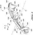
- Fig. 6 is a perspective view of an exemplary device 600, 128 for guiding bleed air 208 into the bypass duct 104 of the turbofan engine 100.
- Fig. 7 is a view of the device 600, 128 of Fig. 6 viewed toward the fore direction along the central axis 114 when the device 600, 128 is installed in the turbofan engine 100.
- device 600, 128 may be a louver that is installed to replace the louver 302, 128.
- the device 600, 128 may define part of the radially extending bleed air passage 206 in the turbofan engine 100, between the bypass duct 104 and the core engine 122.
- the device 600, 128 may at least partially wrap angularly along the inner casing 106 of the turbofan engine 100 in between the core engine 122 and the bypass duct 104.
- the device 600, 128 may guiding bleed air 208 into the bypass duct 104.
- the device 600, 128 includes a body 626 with a radially-outer edge 616 and a radially-inner edge 618, relative to the central axis 114.
- the radially-outer edge 616 and radially-inner edge 618 may be at least partially spaced apart in the radial direction 118 by a radial distance 608 and may also be spaced apart in the axial direction 120.
- the body 626 defines a first flow-guiding surface 604A having a first end 610A and an opposite second end 612A, which are angularly spaced apart from each other relative to the central axis 114.
- the body 626 defines a second flow-guiding surface 604B having a first end 610B and an opposite second end 612B, which are angularly spaced apart from each other relative to the central axis 114.
- the second flow-guiding surface 604B is angularly spaced apart from the first flow-guiding surface 604B relative to the central axis 114.
- the first ends 610A, 610B and respective second ends 612A, 612B opposite thereto define respective spans 620A, 620B of the flow-guiding surfaces 604A, 604B around the central axis 114.
- the flow-guiding surfaces 604A, 604B each extend between the radially-inner edge 618 and the radially-outer edge 616 of the body 626.
- the first end 610A is distal to the second flow-guiding surface 604B and the second end 612A is relatively proximal to the second flow-guiding surface 604B.
- the first end 610B is proximal to the first flow-guiding surface 604A and the second end 612B is relatively distal to the first flow-guiding surface 604A.
- the body 626 includes a side wall 602A adjacent the first end 610A of the flow-guiding surface 604A.
- the first side wall 602A extends at least partially axially relative to the central axis 114.
- the device 600, 128 includes a second side wall 602B adjacent the second end 612B of the second flow-guiding surface 604B.
- the second side wall 602B extends at least partially axially relative to the central axis 114.
- the second side wall 602B may be a mirror image of the first side wall 602A.
- one or both of the side walls 602A, 602B may be substantially parallel to the central axis 114.
- One or both of the side walls 602A, 602B may be substantially planar/flat.
- one or both of the side walls 602A, 602B may be non-planar and may extend in both the angular direction 402 and the axial direction 120.
- one or both of the side walls 602A, 602B may be curved and/or may be non-parallel to the radial direction 118.
- One or both of the side walls 602A, 602B may extend from a respective first position 622A, 622B radially inwardly of the radially-inner edge 618 to a respective second position 624A, 624B radially outwardly of the radially-inner edge 618 relative to the central axis 114.
- One or both of the side walls 602A, 602B may extend radially (in the radial direction 118) towards the central axis 114 beyond the radially-inner edge 618 of the body 626.
- the side walls 602A, 602B may extend radially outwardly to the radially-outer edge 616 of the body 626.
- the side walls 602A, 602B may define part of the bleed air passage 206 and may each block or hinder some transverse flow in the bleed air passage 206.
- One or both of the side walls 602A, 602B may be formed continuously with the radially-inner edge 618 via a blended corner disposed at each of the first end 610A and the second end 612B.
- One or both of the side walls 602A, 602B may terminate at the respective first position 622A, 622B.
- One or both of the second positions 624A, 624B may be adjacent the radially-outer edge 616 of the body 626.
- one or both of the second positions 624A, 624B may be disposed radially inwardly of the radially-outer edge 616 of the body 626. In some embodiments, one or both of the second positions 624A, 624B may be disposed radially inwardly of, or at the same radial position as the radially-outer edge 616 of the body 626. In some embodiments, one or both of the first positions 622A, 622B may be radially inward of the radially-inner edge 618 by an amount between 5% and 100% of the radial distance 608 between the radially-inner edge 618 and the radially-outer edge 616.
- one or both of the first positions 622A, 622B may be radially inward of the radially-inner edge 618 by an amount between 10% and 50% of the radial distance 608 between the radially-inner edge 618 and the radially-outer edge 616.
- Each or both of the side walls 602A, 602B may be inclined at an inclination angle 704 relative to the radial direction 118.
- the inclination angle 704 may be between 0 and 45 degrees.
- Each or both of the side walls 602A, 602B may be inclined towards each other in the radially-outward direction so that radially outward ends of the side walls 602A, 602B may be angularly closer to each other than their radially inward ends.
- the device 600, 128 includes a third side wall 614A adjacent the second end 612A of the first flow-guiding surface 604A of the body 626.
- the device 600, 128 includes a fourth side wall 614B adjacent the first end 610B of the second flow-guiding surface 604B of the body 626.
- Both of the third and fourth side walls 614A, 614B extend at least partially axially relative to the central axis 114.
- Both of the third and fourth side walls 614A, 614B are substantially planar and divergent relative to each other in a radially outward direction relative to the central axis 114.
- the side walls 614A, 614B may be oriented so that radially inward ends of the side walls 614A, 614B may be closer to each other than their radially outward ends relative to the central axis 114.
- the third and fourth sidewalls may cooperatively define a V-shaped center piece 606 that is pointing radially-inwardly.
- the center piece 606 may be positioned between first and second flow-guiding surfaces 604A, 604B.
- the center piece 606 may be substantially aligned with the bridge 902 defined in the inner casing 106 between the openings 306A, 306B (see Fig. 12 ).
- the center piece 606 may direct the flow around the bridge 902 as the bleed air 208 flows towards the bypass duct 104.
- the center piece 606 may help reduce transverse flows in the bleed air 208.
- One or more of the side walls 602A, 602B may have a unitary construction with the body 626 or may be separately-manufactured components that are subsequently assembled with the body 626 via fasteners or other means.
- a unitary construction refers to a construction of the two parts wherein each is fused or melded to the other to form a single entity.
- one or more of the side walls 602A, 602B may be manufactured together with the body 626 as a single piece.
- the center piece 606 may have a unitary construction with the body 626.
- the device 600, 128 may be manufactured by injection molding, casting, additive manufacturing, welding, machining and/or brazing.
- the device 600, 128 may be made of a suitable metallic material, polymer or fibre-reinforced composite material for example.
- any of the side walls 602A, 602B and center piece 606 may be separate from the body 626.
- any of the side walls 602A, 602B and the centerpiece 606 may be integrated with and/or have a unitary construction with the inner casing 106.
- some or all of device 600, 128 may be integrated with and/or have a unitary construction with the inner casing 106.
- the device 600, 128 may have a different number of side walls and center pieces than those illustrated herein.
- Fig. 8 is an enlarged view of the region 702 of Fig. 7 showing the side wall 602B of the device 600, 128.
- the side wall 602B in Fig. 7 is viewed substantially along the central axis 114.
- the side wall 602A may be a mirror image of the sidewall 602B about the center piece 606.
- the side wall 602B when viewed along the central axis 114 may have a linear profile 804.
- the linear profile 804 may be inclined relative to a radial direction to central axis 114.
- the side walls 602A, 602B may have a rounded or curved profile such as a Bellmouth profile 802, or bell-shaped profile, when viewed along the central axis 114.
- the Bellmouth profile 802 may smoothly or tangentially transition to a linear (or straight) profile at a radially outer end of the side wall 602B.
- the radially outer end of the Bellmouth profile 802 may be inclined at an angle 704 between 0 and 45 degrees, similar to the inclination of the linear profile 804 as shown in Fig. 7 .
- the body 626 may comprise a single row of angularly-spaced apart flow-guiding surfaces 604A, 604B (or vanes, or airfoil-shaped bodies, or aerodynamic surfaces) in the axial direction 120.
- the side walls 602A, 602B may not provide significant structural support but may help reduce transverse flows by modifying the flow in the bleed air passage 206.
- Fig. 9 is a perspective view along a cross-section taken along line 9-9 of Fig. 7 of a portion of the turbofan engine 100 equipped with the device 600, 128 disposed in the inner casing 106 opposite the baffle 304, 128.
- the device 600, 128 may be used in conjunction with the baffle 304, 128 (shown in Fig. 3 ) or other baffles described herein.
- Fig. 10 is another perspective view of a portion of the turbofan engine 100 of Fig. 9 showing the device 600, 128.
- Fig. 11 is another perspective view of a portion of the turbofan engine 100 of Fig. 9 , showing a detailed view of an end of the device 600, 128 adjacent to the inner casing 106.
- the device 600, 128 may guide bleed air 208 immediately before the bleed air 208 enters the bypass duct 104 via the openings 306A, 306B formed in the inner casing 106.
- the device 600, 128 may define part of a bleed air passage 906 in cooperation with the axially spaced apart baffle 304, 128 to form one or more channels for conveying bleed air 208 towards the bypass duct 104.
- one or both of the flow-guiding surfaces 604A, 604B may define a wall of the bleed air passage 906 while the baffle 304, 128 may form an opposing wall of the bleed air passage 906.
- the device 600, 128 may be adapted to the inner casing 106 to form a substantially continuous wall of the bleed air passage 906.
- gaps may be formed between the device 600, 128 and adjacent components to prevent contact/fretting between parts during operation.
- a gap 912 may be defined between the center piece 606 and the baffle 304, 128.
- Another gap 914 may be defined between the center piece 606 and the inner casing 106.
- the baffle 304, 128 and the flow-guiding surfaces 604A, 604B may be spaced apart in the axial direction 120.
- the flow-guiding surfaces 604A, 604B may be concave relative to the bleed air passage 906 and may respectively guide bleed air 208 to respective openings 306A, 306B formed in the inner casing 106.
- a plurality of devices 600, 128 may be circumferentially distributed about the central axis 114 and be associated with respective bleed air passages 906 also circumferentially distributed about the central axis 114.
- the flow-guiding surfaces 604A, 604B may have leading edges adjacent the radially-inner edge 618 of the body 626 and may have trailing edges adjacent the radially-outer edge 616 of the body 626.
- a general flow direction of the bleed air 208 is indicated at 910 in Figs. 10 and 11 .
- the expression "general flow direction" as used herein is intended to refer to a main or overall streamwise direction of flow of the fluid in question.
- the general flow direction of the bleed air 208 may vary along the bleed air passage 906.
- the general flow direction of the bleed air 208 may have both radial and axial components relative to the engine 100.
- Fig. 12 shows the openings 306A, 306B of the bleed air passage 906 to the bypass duct 104 in conjunction with the device 600, 128.
- Fig. 12 represents a radially-inward view of the openings 306A, 306B from within the bypass duct 104.
- Fig. 13 is a flow chart of a method 1300 of operating the turbofan engine 100.
- the method 1300 may be carried out using device 600, 128. Aspects of the method 1300 may be combined with aspects of other methods described herein.
- the method 1300 may include: receiving bleed air 208 from the core engine 122 of the turbofan engine 100 (block 1302); guiding the bleed air 208 along a streamwise direction 518 into the bypass duct 104 using a flow-guiding surface 604A and/or 604B defining part of the annulus 520 extending partially around the central axis 114 of the turbofan engine 100 (block 1304); and hindering the transverse flow 516 of bleed air 208 that is transverse to the streamwise direction 518, the hindering of the transverse flow 516 being conducted at a first streamwise location coincident with the flow-guiding surface 604A, and at a second streamwise location that is upstream of the flow-guiding surface 604A (block 1306)
- the first streamwise location may be proximal to or adjacent to the radially-inner edge 618 of the device 600, 128.
- the hindering of the transverse flow 516 of bleed air 208 may be performed using one or more side walls 602A, 602B, 614A, 614B.
- Fig. 14 is a schematic cross-sectional view of an exemplary louver 1500, 128 of the turbofan engine 100 taken in the plane 318 parallel to and containing the central axis 114.
- the louver 1500 may also include one or more side walls 602A, 602B, 614A, 614B of the device (e.g., louver) 600 (shown in Fig. 6 ).
- Fig. 15 is an enlarged view of the louver 1500, 128.
- the louver 1500, 128 may partially defines the bleed air passage 1406 conveying the bleed air 208 toward the bypass duct 104.
- the louver 1500, 128 may comprise a structure with a break in a camber line near its trailing edge. The break forms a protrusion in the bleed air passage 1406 that narrows the bleed air flow 312 path into the bypass duct 104.
- a portion 1404 of the louver 1500, 128 jutting out into the bleed air passage 1406 at the trailing end of the louver 1500, 128 may partially block the flow of bleed air 208 and narrow the bleed air passage 1406 defined between the louver 1500 and the baffle 304, 128.
- the protruding portion 1404 of the louver 1500, 128 can lead to generation of one or more relatively low pressure regions 1420 downstream of the louver 1500, 128.
- the region 1420 may promote attachment of the bypass air 214 to the inner
- the louver 1500, 128 may include an upstream portion 1402 disposed upstream of the protruding portion 1404.
- the upstream portion 1402 may define a leading end 1414 and a trailing end 1416.
- the protruding portion 1404 may be adjacent the trailing end 1416 of the upstream portion 1402.
- the upstream portion 1402 and protruding portion 1404 may have a unitary construction.
- the upstream portion 1402 may define a flow-guiding surface 1410.
- the flow-guiding surface 1410 may define part of the bleed air passage 1406.
- the upstream portion 1402 may have a first camber line 1506 extending between the leading end 1414 and the trailing end 1416.
- the protruding portion 1404 may have a second camber line 1508.
- Camber lines 1506 and 1508 may be respective lines joining the leading and trailing edges of an airfoil equidistant from the opposed upper and lower surfaces.
- the two opposed surfaces may be outer surface 1418 and inner flow-guiding surface 1410 of the louver 1500, 128.
- the two opposed surfaces may be the inner protruding surface 1412 and an outer surface 1530.
- the first camber line 1506 may be curved or arcuate.
- the second camber line 1508 may be substantially linear. In some embodiments, the second camber line 1508 may be curved or arcuate.
- Fig. 16 is an enlarged view of a camber line intersection region 1600 of Fig. 15 .
- An intersecting angle 1502 (shown in Fig. 15 ) may be defined between a tangent line 1602 of the first camber line 1506 and a tangent line 1604 of the second camber line 1508 at an intersection point 1606.
- the intersecting angle 1502 (shown in FIG. 15 ) may be between 45 and 135 degrees.
- a length 1522 of the second camber line 1508 may be between 4% and 40% of a sum of a length 1524 of the first camber line 1506 and a length 1522 of the second camber line 1508.
- a width 1520 of the protruding portion 1404 measured transversely to the second camber line 1508 may be between 2% and 40% of a sum of the length 1524 of the first camber line 1506 and the length 1522 of the second camber line 1508.
- the second camber line 1508 of protruding portion 1404 may form a discontinuity 1608 in tangency with the first camber line 1506.
- the tangent line 1602 and tangent line 1604 may have different slopes.
- the discontinuity 1608 may occur between an end of the second camber line 1508 closest to the first camber line 1506 and an end of the first camber line 1506 closest to the second camber line 1508, e.g. the intersection point 1606.
- the protruding surface 1412 may be adjacent the flow-guiding surface 1410.
- the protruding surface 1412 may have curvature different than the curvature of the flow-guiding surface 1410.
- the curvature may be an average curvature or may be considered at a particular position, e.g. the intersection point 1606.
- the flow-guiding surface 1410 may have a curved cross-sectional profile 1516 and the protruding surface 1412 may have a linear cross-sectional profile 1512, in the plane 318.
- the profiles are shown in Fig. 15 extending from the louver 1500, 128 as dashed lines with circle markers.
- the protruding surface 1412 may intersect the flow-guiding surface 1410 and may be oriented at an angle 1504 between 45 and 135 degrees to the flow-guiding surface 1410.
- the flow-guiding surface 1410 may guide the bleed air 208 received from the core engine 122 toward a general bypass flow direction 1424 (shown in Fig. 14 ) of bypass air flowing into the bypass duct 104, resulting in a guided flow 1526 that tends towards the general bypass flow direction 1424.
- the protruding portion 1404 may cause the bleed air 208 to swerve by providing an abrupt or steep flow obstruction.
- the resulting diverted flow 1528 may flow around the protruding portion 1404 before entering the bypass duct 104.
- the swerving may include guiding some of the bleed air 208 away from the bypass duct 104.
- swerving may include momentarily guiding some of the bleed air 208 towards the central axis 114 before allowing the bleed air 208 to enter the bypass duct 104.
- the protruding portion may create a region 1420 of relatively low pressure downstream of the louver 1500, 128. In some situations, the region 1420 of low pressure may draw the bypass flow 202 toward the inner casing 106.
- Fig. 17 is a flow chart of a method 1700 of guiding bleed air 208 in the turbofan engine 100.
- the method 1700 may be performed using the louver 1500, 128.
- the method 1700 may include: guiding the bleed air 208 received from the core engine 122 toward a general bypass flow direction 1424 of bypass air 214 flowing into the bypass duct 104 (block 1702); after guiding the bleed air 208 toward the general bypass flow direction 1424, causing the bleed air 208 to swerve (block 1704); and after causing the bleed air 208 to swerve, discharging the bleed air 208 into the bypass duct 104 (block 1706).
- the bleed air 208 is discharged into the bypass duct 104 via an opening 1408 through the inner casing 106 of the turbofan engine 100 defining part of the bypass duct 104, and a region 1420 of relatively low pressure is generated in the bypass duct 104 at or upstream of the opening 1408 to draw the bypass air 214 toward the inner casing 106.
- causing the bleed air 208 to swerve includes guiding the bleed air 208 radially inwardly relative to the central axis 114 of the turbofan engine 100.
- a louver 1500, 128 may be used to: guide the bleed air 208 toward the bypass flow direction 1424; cause the bleed air 208 to swerve; and cause the region 1420 of relatively low pressure in the bypass duct 104 at or upstream of the opening 1408 through the inner casing 106.
- Fig. 18 is a schematic cross-sectional view of an exemplary bleed air duct 1800, 128 of the turbofan engine 100 in the plane 318, showing contours of Mach number in the bleed air passage 1816 defined by the bleed air duct 1800, 128 as represented by the contour levels 1814.
- Fig. 19 is a schematic cross-sectional view of the bleed air duct 1800, 128 of Fig. 18 in the plane 318, showing streamlines of flow in the bleed air passage 1816 and which are shaded by speed as represented by the contour levels 1902.
- Fig. 20 is an enlarged view of region 2000 of Fig. 19 .
- the bleed air duct 1800, 128 may comprise a louver 1804 and a baffle 1812.
- the baffle 1812 and the louver 1804 may define part of the bleed air passage 1816.
- the baffle 1812 may have a curved cross-sectional profile, such as an S-shape or concave-convex shape profile in an axial-radial plane 318.
- the baffle 1812 may direct the bleed air 208 in a manner that promotes desirable flow conditions in the bypass duct 104.
- the louver 1804 may also include one or more side walls 602A, 602B, 614A, 614B of the device (e.g., louver) 600 (shown in Fig. 6 ) and/or protruding portion 1404 of the louver 1500 (shown in Fig. 15 ).
- the device e.g., louver 600 (shown in Fig. 6 ) and/or protruding portion 1404 of the louver 1500 (shown in Fig. 15 ).
- the bleed air duct 1800, 128 may convey the bleed air 208 from the core engine 122 to the bypass duct 104 of the turbofan engine 100 via an opening 1808 formed through the inner casing 106.
- the bleed air passage 1816 may extend angularly partially around the central axis 114.
- the bleed air duct 1800, 128 may include a first duct portion 1820 (shown in Fig. 18 ) configured to convey the bleed air 208 along a general bleed flow direction 1810.
- the general bleed flow direction 1810 may be transverse to the general bypass flow direction 1824.
- an angle 1914 between the general bleed flow direction 1810 and the bypass flow direction 1824 may be between 45 and 120 degrees, between 60 and 120 degrees, between 60 and 105 degrees, between 75 and 105 degrees, or about 90 degrees of the general bypass flow direction 1824 of the bypass duct 104.
- a second duct portion 1802 may be disposed (e.g., immediately) downstream of the first duct portion 1820.
- the second duct portion 1802 may be configured to guide the bleed air 208 from the general bleed flow direction 1810 toward the general bypass flow direction 1824.
- the second duct portion 1802 may include the baffle 1812.
- the baffle 1812 may have a cross-sectional profile 1908 in the plane 318 parallel to and intersecting the central axis 114.
- the baffle 1812 may include a concave portion 1822 that is concave relative to the bleed air passage 1816 and a convex portion 1806 that is convex relative to the bleed air passage 1816.
- the convex portion 1806 may be disposed downstream of the concave portion 1822.
- the convex portion 1806 may include a curved portion protruding into the bleed air duct 1800, 128.
- the concave portion 1822 may correspond to a depression or recessed portion of the bleed air passage 1816.
- Either or both of the concave portion 1822 and convex portion 1806 may be curved.
- the cross-sectional profile of convex portion 1806 may be bow-shaped or arcuate.
- the convex portion 1806 and concave portion 1822 may respectively define a convex surface and a concave surface of the baffle 1812 exposed to bleed air flow 312.
- the baffle 1812 may have a unitary construction including both the convex portion 1806 and the concave portion 1822.
- the baffle 1812 may be made of multiple pieces assembled together.
- the baffle 1812 may be made from forming a suitable sheet metal for example.
- the baffle 1812 may be made from a polymer or fibre-reinforced composite material for example.
- the concave portion 1822 and convex portion 1806 may smoothly connect (e.g., be tangent continuous) to form a continuous flow-guiding surface.
- the convex portion 1806 of the cross-sectional profile 1908 may be longer than the concave portion 1822 of the cross-sectional profile 1908. The length may be measured using arc length of the cross-sectional profile 1908 and/or the length along the general bleed flow direction 1810.
- the cross-sectional profile 1908 may have a chord 1904 of maximum chord length that is substantially parallel to the general bleed flow direction 1810.
- the cross-sectional profile 1908 may have a maximum height 1906 from the chord 1904.
- the maximum height 1906 provides a measure of the depth of the baffle 1812, or a convex portion 1806 thereof, into the bleed air passage 1816.
- the maximum height 1906 may be between 5% and 100% of the length of the chord 1904.
- the maximum height 1906 may be between 10% and 50% of the length of the chord 1904.
- the maximum height 1906 may be between 5% and 75% of the length of the chord 1904.
- the configuration of the cross-sectional profile 1908 of the baffle 1812 may depend on the amount of space available to accommodate the bump in the baffle 1812 defined by the maximum height 1906.
- the bump in the baffle 1812 pushes the flow to the left (i.e., forward) and then guides the flow to the right (i.e., aft) before being discharged into the bypass duct 104.
- the louver 1804 may cooperate with the baffle 1812 to define the part of the bleed air passage 1816.
- the baffle 1812 may be disposed aft of the louver 1804 relative to the central axis 114.
- the louver 1804 may cooperate with the convex portion 1806 of the baffle 1812 to define a throat 1910 of the bleed air passage 1816.
- the throat 1910 may be a section of the bleed air passage 1816 between the louver 1804 and baffle 1812 having a shortest distance between the louver 1804 and baffle 1812.
- the throat 1910 may be located substantially at a trailing end of the louver 1804.
- a concave-convex (or S-shaped) baffle 1812 may, in some embodiments, cause the (turbulence) diffusion rate on the baffle 1812 to be reduced and the flow separation in the bypass duct 104 to be reduced. In some embodiments, an ensuing pressure drop 220 may be reduced compared to other configurations.
- Fig. 19 and ( Fig. 20 ) shows that the flow remains substantially attached to the baffle 1812 at the trailing edge 1912 of the baffle 1812.
- the concave-convex configuration of the baffle 1812 may cause bleed air flow 312 (shown in FIG. 20 ) to adopt an orientation that is partially in opposition to the general bypass flow direction 1824 in the concave portion 1822, and then, in the convex portion 1806, cause the bleed air flow 312 to turn toward the general bypass flow direction 1824.
- Fig. 21 is a flow chart of a method 2100 of guiding bleed air 208 in the turbofan engine 100 having a core engine 122 and the bypass duct 104.
- the method 2100 may be performed using baffle 1812.
- the method 2100 may include conveying the bleed air 208 received from the core engine 122 along a general bleed flow directions 1820 that is between 60 and 120 degrees (or between 45 and 120 degrees, between 60 and 105 degrees, between 75 and 105 degrees, or about 90 degrees) of the general bypass flow direction 1424 of the bypass duct 104 (block 2102); after conveying the bleed air 208 along the general bleed flow direction 1810, guiding the bleed air 208 away from the general bleed flow direction 1810 (block 2104); after conveying the bleed air 208 along the general bleed flow direction 1810, guiding the bleed air 208 toward the general bleed flow direction 1810 (block 2106); and after guiding the bleed air 208 along the general bleed flow direction 1810, discharging the bleed
- the method 2100 may include guiding the bleed air 208 toward the general bypass flow direction 1824. Some embodiments of the method 2100 may comprise: using a concave surface to guide the bleed air 208 away from the general bleed flow direction 1810; and using a convex surface to guide the bleed air 208 toward the general bleed flow direction 1810 and to guide the bleed air 208 toward the general bypass flow direction 1824.
- Some embodiments of the method 2100 may comprise: after conveying the bleed air 208 along the general bleed flow direction 1810 and before discharging the bleed air 208 into the bypass duct 104, causing a deviation (e.g., chord height 1906) of the bleed air 208 spanning over a distance (e.g., chord 1904) along the general bleed flow direction 1810.
- a maximum amount of the deviation may be 15% or more of the of the distance (e.g., chord 1904) along the general bleed flow direction 1810.
- Fig. 22 is a schematic cross-sectional view of an exemplary baffle 2204, 128 of the turbofan engine 100 in the plane 318 parallel to and containing the central axis 114 of the turbofan engine 100.
- the louver 302 may also include one or more side walls 602A, 602B, 614A, 614B of the device (e.g., louver) 600 (shown in Fig. 6 ) and/or protruding portion 1404 of the louver 1500 (shown in Fig. 15 ).
- the baffle 2204 may also include the convex portion 1806 of the baffle 1812 (shown in Fig. 20 ).
- Fig. 23 is an enlarged view of the region 2300 of Fig. 22 .
- the baffle 2204, 128 may define part of a bleed air duct 2212 at least partially defining a bleed air passage 2210.
- the baffle 2204, 128 defines a flow-guiding surface 2222 for guiding the bleed air 208 toward the bypass duct 104.
- An upstream duct portion 2218 may be configured to convey the bleed air 208 along the general bleed flow direction 2202.
- a downstream duct portion 2220 may be disposed downstream of the upstream duct portion 2218 and may be configured to guide the bleed air 208 from the general bleed flow direction 2202 toward the general bypass flow direction 2206.
- a portion 2304 of the baffle 2204, 128 may protrude into the bypass duct 104 when installed in the turbofan engine 100.
- the portion 2304 may overlap a surface 2224 of the inner casing 106.
- the baffle 2204, 128 may be used to guide the bleed air 208 toward a general bypass flow direction 2206 of the bypass duct 104 at a location upstream of the bypass duct 104. Thereafter, the baffle 2204 may be used to guide the bleed air 208 at a location inside the bypass duct 104 as well.
- a trailing edge 2306 of the baffle 2204 may be disposed inside the bypass duct 104.
- the edge 2306 may be an end of the portion 2304.
- the edge 2306 may be slightly displaced (i.e., raised) from the inner casing 106, such as to form step 2226 inside the bypass duct 104.
- the step 2226 may interact with flow discharging from the bleed air duct 2212 and the bypass flow 202 to generate a low pressure zone 2214 downstream thereof.
- the step 2226 may be a radially-inward displacement between an upstream to a downstream location of the edge 2306.
- the baffle 2204,128 may extend into the bypass duct 104 over the inner casing 106 to create a protrusion in the bypass flow 202 and the region 2214 of relatively low pressure downstream thereof.
- the region of relatively low pressure 2214 may help keep the flow more attached to the inner casing 106 downstream of the opening 2208, thereby reducing the pressure drop 220 in the bypass duct 104.
- the baffle 2204,128 may have a unitary construction or may be made of multiple pieces assembled together.
- the baffle 2204,128 may be made from forming a suitable sheet metal for example.
- the baffle 2204,128 may be made from a polymer or fibre-reinforced composite material for example.
- the step 2226 may have a height between 3% and 10% of the dimension of a throat (such as throat 2616 shown in FIG. 25 ) between the louver 302 and the baffle 2204, 128 shown in Fig. 22 .
- the baffle 2204,128 may include a convex flow-guiding surface 2222 that is convex relative to the bleed air passage 2210.
- the convex flow-guiding surface 2222 may extend into the bypass duct 104.
- the bleed air duct 2212 may include a louver 302, 128 (or other louvers described herein) cooperating with the baffle 2204,128 to guide the bleed air 208 toward the bypass duct 104.
- the baffle 2204,128 may be disposed aft of the louver 302, 128 relative to the central axis 114 of the turbofan engine 100.
- Fig. 24 is a flow chart of a method 2400 of guiding bleed air 208 in the turbofan engine 100 having a core engine 122 and the bypass duct 104.
- the method 2400 may be performed using the baffle 2204.
- the method 2400 may include: conveying the bleed air 208 received from the core engine 122 along the general bleed flow direction 2202 (e.g., between 60 and 120 degrees, between 45 and 120 degrees, between 60 and 105 degrees, between 75 and 105 degrees, or about 90 degrees of the general bypass flow direction 2206) (block 2402); and after conveying the bleed air 208 along the general bleed flow direction 2202: using a baffle 2204 to guide the bleed air 208 toward the general bypass flow direction 2206 of the bypass duct 104 at a location upstream of the bypass duct 104; and using the baffle 2204 to guide the bleed air 208 at a location inside the bypass duct 104 (block 2404).
- the general bleed flow direction 2202 e.g., between
- Some embodiments of the method 2400 comprise: using a portion 2304 of the baffle 2204,128 protruding into the bypass duct 104 to cause a region of relatively low pressure 2214 inside the bypass duct 104.
- the region of relatively low pressure 2214 may be located downstream of the portion 2304 of the baffle 2204,128 protruding into the bypass duct 104.
- the location inside the bypass duct 104 may be raised from the radially-inner surface 2224 of the bypass duct 104 defined by the inner casing 106.
- the baffle 2204,128 may include the convex flow-guiding surface 2222 that extends into the bypass duct 104.
- the trailing edge 2306 of the baffle 2204,128 may define the step 2226 inside the bypass duct 104.
- Fig. 25 is a schematic axial cross-sectional view of another baffle-louver arrangement which may include a baffle 2602, 128 and a louver 2604, 128.
- the baffle-louver arrangement may define a bleed air passage 2610 between flow-guiding surface 2608 and flow-guiding surface 2612, which may extend angularly partially about the central axis 114.
- the throat 2616 may be defined at the minimum distance between the opposing flow guiding surfaces 2608 and 2612.
- the location of throat 2616 at or near the trailing end 2618 of the louver 2604 may, in some embodiments, promote favorable flow conditions as the bleed air 208 enters the bypass duct 104 via the opening 2606.
- the length of the throat 2616 in the plane 318 may be between 25-40% smaller than the comparable distance at the leading end 2620 of the louver 2604, 128.
- the location of the throat 2616 may be achieved by selection of the geometry of the baffle 2602, 128 and/or the louver 2604, 128.
- the location of the throat 2616 and/or the amount of streamwise area reduction along the louver 2604, 128 may be achieved using various combinations of louvers and baffles described herein.
- the device 600, louver 1500, 128, the louver 302, 128, and the louver 2604, 128 may each be configurable to cooperate with one of the baffles 1812, 2204, 2602.
- the device 600, louver 302, 128, and louver 2604, 128 may each also include a protruding portion such as that of the louver 1500, 128.
- the louver 1500, 128 may include side walls such as those of the device 600, 128.
- the baffle 1812, 128 may include a portion protruding into the bypass duct 104 such as that of the baffle 2204, 128.
- Other combinations of various embodiments louvers and baffles described herein are contemplated.
Description
- The disclosure relates generally to turbofan engines and, more particularly, to devices and methods for facilitating the discharge of bleed air into a bypass duct of a turbofan engine.
- Bypass flow generated by a fan of a turbofan engine may provide a substantial portion of the overall propulsive thrust generated by the turbofan engine. In some situations, it is desirable to direct some compressed air from a core gas path of the turbofan engine into a bypass duct of the turbofan engine to achieve a desired operating condition of the turbofan engine. Such bleed of the compressed air into the bypass duct may be achieved via a bleed-off valve and a bleed air passage opening into the bypass duct. Directing the compressed air (also called "bleed air") to the bypass duct may result in energy losses due to disruptive airflows and modification of the bypass flow caused by the bleed air discharge. Improvement is desired.
-
US 2019/0345875 A1 discloses a prior art intermediate housing hub comprising discharge flow guiding channels formed by the discharge fins. -
US 2015/0275757 A1 discloses a prior art bleed duct for laminar duct flow, in which a duct mounted within a core nacelle defines a bleed air flow path for directing bleed air from a core engine into a bypass passage. -
US 2015/0176500 A1 discloses a prior art flow outlet, in which a bleed flow discharge device discharges bleed flow into a main fluid flow. - According to a first aspect of the present invention, there is provided a device for guiding bleed air into a bypass duct as set forth in
claim 1. - According to a further aspect of the present invention, there is provided a turbofan engine as set forth in claim 10.
- Further embodiments are provided as set forth in
dependent claims 2 to 9 and 11. - Embodiments may include combinations of the above features.
- Reference is now made to the accompanying figures in which:
-
Fig. 1 is a schematic cross-sectional view of an exemplary turbofan gas turbine engine, including one or more bleed air devices as described herein; -
Fig. 2 is a detailed schematic view ofregion 200 ofFig. 1 , showing an exemplary compressor section and bypass duct of the turbofan engine; -
Fig. 3 is a detailed schematic view ofregion 300 ofFig. 2 , showing a baseline bleed air passage between a core gas path and the bypass duct; -
Fig. 4 is a schematic perspective view of streamlines of flow in a bleed air discharge region of the bypass duct using the bleed air passage ofFig. 3 ; -
Fig. 5 is a schematic view in a forward direction of the streamlines of flow ofFig. 4 ; -
Fig. 6 is a perspective view of an exemplary bleed air device for guiding bleed air into the bypass duct of the turbofan engine; -
Fig. 7 is a front view of the bleed air device ofFig. 6 ; -
Fig. 8 is an enlarged view ofregion 702 ofFig. 7 showing a side wall of the bleed air device ofFig. 6 ; -
Fig. 9 is a perspective view along a cross-section taken along line 9-9 ofFig. 7 of a portion of the turbofan engine equipped with the bleed air device ofFig. 6 ; -
Fig. 10 is another perspective view of a portion of the turbofan engine ofFig. 9 showing the bleed air device ofFig. 6 ; -
Fig. 11 is another perspective view of a portion of the turbofan engine ofFig. 9 , showing a detailed view of an end of the bleed air device ofFig. 6 adjacent to the casing; -
Fig. 12 is a radially-inward view of two openings of the bleed air passage to the bypass duct of the turbofan engine equipped with the bleed air device ofFig. 6 ; -
Fig. 13 is a flow chart of a method of operating the turbofan engine; -
Fig. 14 is a schematic cross-sectional view of another exemplary bleed air device in a plane parallel to and containing a central axis of the turbofan engine; -
Fig. 15 is an enlarged view of the bleed air device ofFig. 14 ; -
Fig. 16 is an enlarged view of a camberline intersection region 1600 ofFig. 15 ; -
Fig. 17 is a flow chart of a method of guiding bleed air in the turbofan engine; -
Fig. 18 is a schematic cross-sectional view of another bleed air device of the turbofan engine in the plane parallel to and containing the central axis of the turbofan engine, showing contours of Mach number in the bleed air passage; -
Fig. 19 is another schematic cross-sectional view of the bleed air device ofFig. 18 in the plane parallel to and containing the central axis, showing streamlines of flow in the bleed air passage; -
Fig. 20 is an enlarged view ofregion 2000 ofFig. 19 ; -
Fig. 21 is a flow chart of another method of guiding bleed air in the turbofan engine; -
Fig. 22 is a schematic cross-sectional view of another exemplary bleed air device of the turbofan engine in the plane parallel to and containing the central axis of the turbofan engine; -
Fig. 23 is an enlarged view ofregion 2300 ofFig. 22 ; -
Fig. 24 is a flow chart of another method of guiding bleed air in the turbofan engine; and -
Fig. 25 is a schematic cross-sectional view of a baffle-louver arrangement of the turbofan engine in the plane parallel to and containing the central axis of the turbofan engine. - Discharging bleed air into the bypass duct of turbofan engines may be achieved via one or more bleed-off valves and one or more bleed air passages opening to the bypass duct. The geometric configuration of an outlet feeding bleed air into the bypass duct may have a significant effect on a flow inside the bypass duct, either directly by modifying the bypass flow or via the bleed air discharge feeding into the bypass duct. For example, pressure losses may be induced in the bypass duct due to bleed air-induced regions of relatively low pressure, such as separation bubbles and vortical flow regions. Pressure loss reductions may be achieved by encouraging favorable flow conditions in the bypass duct via the geometry of bleed air passages feeding bleed air into the bypass duct. In particular, pressure loss reduction may be achieved via devices such as louvers and baffles at least partially forming bleed air passages feeding bleed air into the bypass duct. Various embodiments of such devices are described herein. It is intended that such embodiments of such devices may be used separately or in combination with each other.
- The term "substantially" as used herein may be applied to modify any quantitative representation which could permissibly vary without resulting in a change in the basic function to which it is related.
-
Fig. 1 illustrates aturbofan engine 100, including one or morebleed air devices 128 as described herein. Theturbofan engine 100 may be of a type preferably provided for use in subsonic flight, generally comprising in serial flow communication afan 102 through which ambient air is propelled, acompressor section 108 for pressurizing the air, acombustor 110 in which the compressed air is mixed with fuel and ignited for generating an annular stream of hot combustion gases, and aturbine section 112 for extracting energy from the combustion gases. After energy extraction, the gases exit theturbofan engine 100 via anengine outlet 126.Turbofan engine 100 may include acore gas path 116 including thecompressor section 108.Turbofan engine 100 may also includebypass duct 104. Thecompressor section 108 may comprise one or more stages, and may include a first compressor stage, sometimes called a "booster" compressor downstream of thefan 102. - The
turbofan engine 100 may have acentral axis 114 extending between afore end 130 and anaft end 132 of theturbofan engine 100 relative to afore direction 134 and anaft direction 136. Thefan 102 may be rotatable about thecentral axis 114. Thefan 102 may be driven by acore engine 122 ofturbofan engine 100. Anaxial direction 120 and a substantially perpendicularradial direction 118 may be defined relative to thecentral axis 114. Theturbofan engine 100 may includeinner casing 106 andouter casing 124 housing parts of theturbofan engine 100. Thecore engine 122 may be disposed in theinner casing 106 of theturbofan engine 100 and be disposed radially inwardly of thebypass duct 104. Thebypass duct 104 of theturbofan engine 100 may be defined between theinner casing 106 and theouter casing 124. Theinner casing 106 may extend substantially annularly around thecentral axis 114. Thebypass duct 104 may receive a portion of the air propelled by thefan 102 towards anengine outlet 126 for exhausting into the ambient atmosphere. Thecore engine 122 may receive another portion of the air propelled by thefan 102 in thecore gas path 116 for generating power via combustion in thecombustor 110. -
Fig. 2 is a detailed schematic view of theregion 200 ofFig. 1 , showing part of thecompressor section 108 and of thebypass duct 104 of theturbofan engine 100. Thecompressor section 108 may comprise one or morebladed rotors 212 andstators 210. Ambient air enteringturbofan engine 100 may be split into abypass flow 202 and a core gas path flow 204 viasplitter 218. Thebypass flow 202 may be oriented substantially in theaxial direction 120. Thebypass duct 104 may include a bypass stator 216 (e.g. vane(s)) for guiding thebypass flow 202, and one or more downstream bypass struts 222 providing structural support between theinner casing 106 andouter casing 124. The bypass struts 222 may be disposed downstream of where thebleed air 208 is discharged into thebypass duct 104. In some situations, discharge of thebleed air 208 via thebleed air passage 206 may cause a pressure drop 220 (pressure loss) between the trailing edge of thebypass stator 216 and the leading edge of thebypass strut 222. - During operation of the
turbofan engine 100, it may be desirable to reduce mass flow rate in thecore engine 122 by discharging some air from thecore gas path 116 into thebypass duct 104. Such a discharge may reduce flow in thecore engine 122 to promote the operation of thecompressor section 108 within a prescribed operational envelope. This portion of air discharged into thebypass duct 104 may be bled from a location within thecompressor section 108 or a location downstream of thecompressor section 108 and upstream of thecombustor 110 such as (immediately or further) downstream of the booster compressor. - The
bleed air 208 may be discharged via ableed air passage 206. Thebleed air passage 206 may be defined between thecore gas path 116 and thebypass duct 104. Thebleed air passage 206 may open, at an upstream end thereof, to thecore gas path 116. Thebleed air passage 206 may extend at least partially in aradial direction 118 so that the upstream and downstream ends of thebleed air passage 206 are radially spaced apart relative tocentral axis 114. Thebleed air 208 may be guided into thebypass duct 104 using one or morebleed air devices 128 to promote desirable flow conditions and reduce pressure loss. -
Fig. 3 is a detailed schematic view of theregion 300 ofFig. 2 , showing thebleed air passage 206 conveyingbleed air 208 along thebleed air flow 312 from thecore gas path 116 to thebypass duct 104.Fig. 3 shows a schematic cross-sectional view of a baseline configuration of thebleed air passage 206 in aplane 318 parallel to and containing thecentral axis 114 of theturbofan engine 100. - The
bleed air passage 206 may be opened or closed via a bleed-offvalve 314. The bleed-offvalve 314 may comprise a movable and selectively actuatable valve member which may be opened when bleed air discharge is desired. The bleed-offvalve 314 may be translatable alongdirection 316 to open/close thebleed air passage 206. The bleed-offvalve 314 is shown as being open inFig. 3 . - The
louver baffle bleed air 208 from thebleed air passage 206 into thebypass duct 104 via anopening 306 through theinner casing 106. Thelouver louver surface 308 relative to thecentral axis 114. Thebaffle surface 310 relative to thecentral axis 114. Thebaffle bleed air passage 206 and may guide thebleed air flow 312 toward thebypass duct 104. -
Fig. 4 is a schematic perspective view ofstreamlines 406 of flow in a bleedair discharge region 400 of thebypass duct 104 of thebaseline bypass duct 206 ofFig. 3 . Thestreamlines 406 are shaded by velocity magnitude as represented by thecontour levels 404. The perspective view has primary alignment along a 2D plane containing theradial direction 118 and theaxial direction 120. Thestreamlines 406 are shown starting in thebleed air passage 206 and extending in thebypass duct 104. Aregion 408 of relatively low pressure adjacent to theopening 306 may be formed. The pressure in such a region of relatively low pressure may be lower than pressure in adjacent flow volumes in thebypass duct 104 and may induce pressure loss in thebypass duct 104. Theregion 408 of relatively low pressure may be a flow separation zone (e.g. a recirculation bubble) adjacent to theopening 306. -
Fig. 5 is a schematic view in theforward direction 134 ofstreamlines 514 of flow in the bleedair discharge region 400. Thestreamlines 514 are shaded by velocity magnitude as represented by thecontour levels 512, and are shown in a region near thebleed air passage 206 opening into thebypass duct 104.FIG. 5 is an angular portion of an annular section of theturbofan engine 100. Thebleed air passage 206 may be part of anannulus 520 extending partially around thecentral axis 114. - Bleed
air 208 flows generally along theradial direction 118 outwardly relative to thecentral axis 114 towards and into thebypass duct 104 as illustrated by thestreamlines 514. Thebleed air 208 flowing towards thebypass duct 104 via thebleed air passage 206 may flow generally along thestreamwise direction 518. - As shown by the
streamlines 514, atransverse flow 516 or secondary flow lateral (e.g. substantially normal) to thestreamwise direction 518 may develop as well. Thetransverse flow 516 may induceundesirable vortices 506 associated with pressure loss in thebypass duct 104. Thetransverse flow 516 may comprise internaltransverse flow 504 within thebleed air passages 206 and externaltransverse flow 502 outside/downstream of thebleed air passages 206 in thebypass duct 104. The internaltransverse flow 504 may result in internal vortical structures that may extend beyond thebleed air passage 206. The externaltransverse flow 502 may result in the formation ofvortices 506 that may cause pressure losses in thebypass duct 104. - Various embodiments of
bleed air devices 128 and methods for guidingbleed air 208 are presented below. In some embodiments, thebleed air devices 128 described herein may promote favorable flow behavior and the reduction of energy loss. In some embodiments, thebleed air devices 128 described herein may guide the flow into thebypass duct 104 in a manner that promotes more favorable flow conditions and that may reduce pressure losses in thebypass duct 104. -
Fig. 6 is a perspective view of anexemplary device 600, 128 for guidingbleed air 208 into thebypass duct 104 of theturbofan engine 100. -
Fig. 7 is a view of thedevice 600, 128 ofFig. 6 viewed toward the fore direction along thecentral axis 114 when thedevice 600, 128 is installed in theturbofan engine 100. In reference toFIG. 3 ,device 600, 128 may be a louver that is installed to replace thelouver device 600, 128 may define part of the radially extendingbleed air passage 206 in theturbofan engine 100, between thebypass duct 104 and thecore engine 122. Thedevice 600, 128 may at least partially wrap angularly along theinner casing 106 of theturbofan engine 100 in between thecore engine 122 and thebypass duct 104. Thedevice 600, 128 may guiding bleedair 208 into thebypass duct 104. - The
device 600, 128 includes abody 626 with a radially-outer edge 616 and a radially-inner edge 618, relative to thecentral axis 114. The radially-outer edge 616 and radially-inner edge 618 may be at least partially spaced apart in theradial direction 118 by aradial distance 608 and may also be spaced apart in theaxial direction 120. - The
body 626 defines a first flow-guidingsurface 604A having afirst end 610A and an oppositesecond end 612A, which are angularly spaced apart from each other relative to thecentral axis 114. Thebody 626 defines a second flow-guidingsurface 604B having afirst end 610B and an oppositesecond end 612B, which are angularly spaced apart from each other relative to thecentral axis 114. The second flow-guidingsurface 604B is angularly spaced apart from the first flow-guidingsurface 604B relative to thecentral axis 114. - The first ends 610A, 610B and respective second ends 612A, 612B opposite thereto define
respective spans surfaces central axis 114. The flow-guidingsurfaces inner edge 618 and the radially-outer edge 616 of thebody 626. - In reference to the first flow-guiding
surface 604A, thefirst end 610A is distal to the second flow-guidingsurface 604B and thesecond end 612A is relatively proximal to the second flow-guidingsurface 604B. In reference to the second flow-guidingsurface 604B, thefirst end 610B is proximal to the first flow-guidingsurface 604A and thesecond end 612B is relatively distal to the first flow-guidingsurface 604A. - The
body 626 includes aside wall 602A adjacent thefirst end 610A of the flow-guidingsurface 604A. Thefirst side wall 602A extends at least partially axially relative to thecentral axis 114. Thedevice 600, 128 includes asecond side wall 602B adjacent thesecond end 612B of the second flow-guidingsurface 604B. Thesecond side wall 602B extends at least partially axially relative to thecentral axis 114. In some embodiments, thesecond side wall 602B may be a mirror image of thefirst side wall 602A. - In some embodiments, one or both of the
side walls central axis 114. One or both of theside walls side walls angular direction 402 and theaxial direction 120. In some embodiments, one or both of theside walls radial direction 118. - One or both of the
side walls first position inner edge 618 to a respectivesecond position inner edge 618 relative to thecentral axis 114. One or both of theside walls central axis 114 beyond the radially-inner edge 618 of thebody 626. Theside walls outer edge 616 of thebody 626. - The
side walls bleed air passage 206 and may each block or hinder some transverse flow in thebleed air passage 206. One or both of theside walls inner edge 618 via a blended corner disposed at each of thefirst end 610A and thesecond end 612B. One or both of theside walls first position second positions outer edge 616 of thebody 626. In some embodiments, one or both of thesecond positions outer edge 616 of thebody 626. In some embodiments, one or both of thesecond positions outer edge 616 of thebody 626. In some embodiments, one or both of thefirst positions inner edge 618 by an amount between 5% and 100% of theradial distance 608 between the radially-inner edge 618 and the radially-outer edge 616. In some embodiments, one or both of thefirst positions inner edge 618 by an amount between 10% and 50% of theradial distance 608 between the radially-inner edge 618 and the radially-outer edge 616. - Each or both of the
side walls inclination angle 704 relative to theradial direction 118. In some embodiments, theinclination angle 704 may be between 0 and 45 degrees. Each or both of theside walls side walls - The
device 600, 128 includes athird side wall 614A adjacent thesecond end 612A of the first flow-guidingsurface 604A of thebody 626. Thedevice 600, 128 includes afourth side wall 614B adjacent thefirst end 610B of the second flow-guidingsurface 604B of thebody 626. Both of the third andfourth side walls central axis 114. Both of the third andfourth side walls central axis 114. For example, theside walls side walls central axis 114. In other words, the third and fourth sidewalls may cooperatively define a V-shapedcenter piece 606 that is pointing radially-inwardly. Thecenter piece 606 may be positioned between first and second flow-guidingsurfaces - When the
device 600, 128 is installed in theturbofan engine 100, thecenter piece 606 may be substantially aligned with thebridge 902 defined in theinner casing 106 between theopenings Fig. 12 ). Thecenter piece 606 may direct the flow around thebridge 902 as thebleed air 208 flows towards thebypass duct 104. In some embodiments, thecenter piece 606 may help reduce transverse flows in thebleed air 208. - One or more of the
side walls body 626 or may be separately-manufactured components that are subsequently assembled with thebody 626 via fasteners or other means. As referred to herein, a unitary construction refers to a construction of the two parts wherein each is fused or melded to the other to form a single entity. For example, in some embodiments, one or more of theside walls body 626 as a single piece. In some embodiments, thecenter piece 606 may have a unitary construction with thebody 626. Thedevice 600, 128 may be manufactured by injection molding, casting, additive manufacturing, welding, machining and/or brazing. In various embodiments, thedevice 600, 128 may be made of a suitable metallic material, polymer or fibre-reinforced composite material for example. - In some embodiments, any of the
side walls center piece 606 may be separate from thebody 626. For example, any of theside walls centerpiece 606 may be integrated with and/or have a unitary construction with theinner casing 106. In various embodiments, some or all ofdevice 600, 128 may be integrated with and/or have a unitary construction with theinner casing 106. Thedevice 600, 128 may have a different number of side walls and center pieces than those illustrated herein. -
Fig. 8 is an enlarged view of theregion 702 ofFig. 7 showing theside wall 602B of thedevice 600, 128. Theside wall 602B inFig. 7 is viewed substantially along thecentral axis 114. Theside wall 602A may be a mirror image of thesidewall 602B about thecenter piece 606. Theside wall 602B when viewed along thecentral axis 114 may have alinear profile 804. Thelinear profile 804 may be inclined relative to a radial direction tocentral axis 114. - In some embodiments, the
side walls Bellmouth profile 802, or bell-shaped profile, when viewed along thecentral axis 114. TheBellmouth profile 802 may smoothly or tangentially transition to a linear (or straight) profile at a radially outer end of theside wall 602B. The radially outer end of theBellmouth profile 802 may be inclined at anangle 704 between 0 and 45 degrees, similar to the inclination of thelinear profile 804 as shown inFig. 7 . - The
body 626 may comprise a single row of angularly-spaced apart flow-guidingsurfaces axial direction 120. In some embodiments, theside walls bleed air passage 206. -
Fig. 9 is a perspective view along a cross-section taken along line 9-9 ofFig. 7 of a portion of theturbofan engine 100 equipped with thedevice 600, 128 disposed in theinner casing 106 opposite thebaffle device 600, 128 may be used in conjunction with thebaffle 304, 128 (shown inFig. 3 ) or other baffles described herein. -
Fig. 10 is another perspective view of a portion of theturbofan engine 100 ofFig. 9 showing thedevice 600, 128. -
Fig. 11 is another perspective view of a portion of theturbofan engine 100 ofFig. 9 , showing a detailed view of an end of thedevice 600, 128 adjacent to theinner casing 106. In relation toFigs. 9-11 , thedevice 600, 128 may guide bleedair 208 immediately before thebleed air 208 enters thebypass duct 104 via theopenings inner casing 106. - The
device 600, 128 may define part of ableed air passage 906 in cooperation with the axially spaced apartbaffle bleed air 208 towards thebypass duct 104. For example, one or both of the flow-guidingsurfaces bleed air passage 906 while thebaffle bleed air passage 906. - In some embodiments, the
device 600, 128 may be adapted to theinner casing 106 to form a substantially continuous wall of thebleed air passage 906. In some embodiments, gaps may be formed between thedevice 600, 128 and adjacent components to prevent contact/fretting between parts during operation. For example, agap 912 may be defined between thecenter piece 606 and thebaffle gap 914 may be defined between thecenter piece 606 and theinner casing 106. - The
baffle surfaces axial direction 120. The flow-guidingsurfaces bleed air passage 906 and may respectively guidebleed air 208 torespective openings inner casing 106. A plurality ofdevices 600, 128 may be circumferentially distributed about thecentral axis 114 and be associated with respectivebleed air passages 906 also circumferentially distributed about thecentral axis 114. - The flow-guiding
surfaces inner edge 618 of thebody 626 and may have trailing edges adjacent the radially-outer edge 616 of thebody 626. A general flow direction of thebleed air 208 is indicated at 910 inFigs. 10 and11 . The expression "general flow direction" as used herein is intended to refer to a main or overall streamwise direction of flow of the fluid in question. The general flow direction of thebleed air 208 may vary along thebleed air passage 906. The general flow direction of thebleed air 208 may have both radial and axial components relative to theengine 100. -
Fig. 12 shows theopenings bleed air passage 906 to thebypass duct 104 in conjunction with thedevice 600, 128.Fig. 12 represents a radially-inward view of theopenings bypass duct 104. -
Fig. 13 is a flow chart of amethod 1300 of operating theturbofan engine 100. In some embodiments, themethod 1300 may be carried out usingdevice 600, 128. Aspects of themethod 1300 may be combined with aspects of other methods described herein. In reference to the figures described above, themethod 1300 may include: receivingbleed air 208 from thecore engine 122 of the turbofan engine 100 (block 1302); guiding thebleed air 208 along astreamwise direction 518 into thebypass duct 104 using a flow-guidingsurface 604A and/or 604B defining part of theannulus 520 extending partially around thecentral axis 114 of the turbofan engine 100 (block 1304); and hindering thetransverse flow 516 ofbleed air 208 that is transverse to thestreamwise direction 518, the hindering of thetransverse flow 516 being conducted at a first streamwise location coincident with the flow-guidingsurface 604A, and at a second streamwise location that is upstream of the flow-guidingsurface 604A (block 1306). The first streamwise location may be proximal to or adjacent to the radially-inner edge 618 of thedevice 600, 128. The hindering of thetransverse flow 516 ofbleed air 208 may be performed using one ormore side walls -
Fig. 14 is a schematic cross-sectional view of anexemplary louver 1500, 128 of theturbofan engine 100 taken in theplane 318 parallel to and containing thecentral axis 114. As shown in stippled lines, the louver 1500 may also include one ormore side walls Fig. 6 ). -
Fig. 15 is an enlarged view of thelouver 1500, 128. Thelouver 1500, 128 may partially defines thebleed air passage 1406 conveying thebleed air 208 toward thebypass duct 104. Thelouver 1500, 128 may comprise a structure with a break in a camber line near its trailing edge. The break forms a protrusion in thebleed air passage 1406 that narrows thebleed air flow 312 path into thebypass duct 104. For example, aportion 1404 of thelouver 1500, 128 jutting out into thebleed air passage 1406 at the trailing end of thelouver 1500, 128 may partially block the flow ofbleed air 208 and narrow thebleed air passage 1406 defined between the louver 1500 and thebaffle portion 1404 of thelouver 1500, 128 can lead to generation of one or more relatively low pressure regions 1420 downstream of thelouver 1500, 128. The region 1420 may promote attachment of thebypass air 214 to theinner casing 106. - The
louver 1500, 128 may include anupstream portion 1402 disposed upstream of the protrudingportion 1404. Theupstream portion 1402 may define aleading end 1414 and a trailingend 1416. The protrudingportion 1404 may be adjacent the trailingend 1416 of theupstream portion 1402. Theupstream portion 1402 and protrudingportion 1404 may have a unitary construction. Theupstream portion 1402 may define a flow-guidingsurface 1410. The flow-guidingsurface 1410 may define part of thebleed air passage 1406. - The
upstream portion 1402 may have afirst camber line 1506 extending between theleading end 1414 and the trailingend 1416. The protrudingportion 1404 may have asecond camber line 1508.Camber lines first camber line 1506, the two opposed surfaces may beouter surface 1418 and inner flow-guidingsurface 1410 of thelouver 1500, 128. In the case of thesecond camber line 1508, the two opposed surfaces may be the inner protrudingsurface 1412 and anouter surface 1530. Thefirst camber line 1506 may be curved or arcuate. Thesecond camber line 1508 may be substantially linear. In some embodiments, thesecond camber line 1508 may be curved or arcuate. -
Fig. 16 is an enlarged view of a camberline intersection region 1600 ofFig. 15 . An intersecting angle 1502 (shown inFig. 15 ) may be defined between atangent line 1602 of thefirst camber line 1506 and atangent line 1604 of thesecond camber line 1508 at anintersection point 1606. In various embodiments, the intersecting angle 1502 (shown inFIG. 15 ) may be between 45 and 135 degrees. - In some embodiments, a
length 1522 of thesecond camber line 1508 may be between 4% and 40% of a sum of alength 1524 of thefirst camber line 1506 and alength 1522 of thesecond camber line 1508. In some embodiments, awidth 1520 of the protrudingportion 1404 measured transversely to thesecond camber line 1508 may be between 2% and 40% of a sum of thelength 1524 of thefirst camber line 1506 and thelength 1522 of thesecond camber line 1508. - The
second camber line 1508 of protruding portion 1404 (shown inFig. 15 ) may form adiscontinuity 1608 in tangency with thefirst camber line 1506. For example, thetangent line 1602 andtangent line 1604 may have different slopes. Thediscontinuity 1608 may occur between an end of thesecond camber line 1508 closest to thefirst camber line 1506 and an end of thefirst camber line 1506 closest to thesecond camber line 1508, e.g. theintersection point 1606. - In reference to
Fig. 15 , the protrudingsurface 1412 may be adjacent the flow-guidingsurface 1410. The protrudingsurface 1412 may have curvature different than the curvature of the flow-guidingsurface 1410. The curvature may be an average curvature or may be considered at a particular position, e.g. theintersection point 1606. The flow-guidingsurface 1410 may have a curvedcross-sectional profile 1516 and the protrudingsurface 1412 may have a linearcross-sectional profile 1512, in theplane 318. The profiles are shown inFig. 15 extending from thelouver 1500, 128 as dashed lines with circle markers. The protrudingsurface 1412 may intersect the flow-guidingsurface 1410 and may be oriented at anangle 1504 between 45 and 135 degrees to the flow-guidingsurface 1410. - In reference to
Figs. 14 and15 , the flow-guidingsurface 1410 may guide thebleed air 208 received from thecore engine 122 toward a general bypass flow direction 1424 (shown inFig. 14 ) of bypass air flowing into thebypass duct 104, resulting in a guidedflow 1526 that tends towards the generalbypass flow direction 1424. The protrudingportion 1404 may cause thebleed air 208 to swerve by providing an abrupt or steep flow obstruction. The resulting divertedflow 1528 may flow around the protrudingportion 1404 before entering thebypass duct 104. In various embodiments, the swerving may include guiding some of thebleed air 208 away from thebypass duct 104. In some embodiments, swerving may include momentarily guiding some of thebleed air 208 towards thecentral axis 114 before allowing thebleed air 208 to enter thebypass duct 104. The protruding portion may create a region 1420 of relatively low pressure downstream of thelouver 1500, 128. In some situations, the region 1420 of low pressure may draw thebypass flow 202 toward theinner casing 106. -
Fig. 17 is a flow chart of amethod 1700 of guidingbleed air 208 in theturbofan engine 100. In some embodiments, themethod 1700 may be performed using thelouver 1500, 128. Themethod 1700 may include: guiding thebleed air 208 received from thecore engine 122 toward a generalbypass flow direction 1424 ofbypass air 214 flowing into the bypass duct 104 (block 1702); after guiding thebleed air 208 toward the generalbypass flow direction 1424, causing thebleed air 208 to swerve (block 1704); and after causing thebleed air 208 to swerve, discharging thebleed air 208 into the bypass duct 104 (block 1706). - In some embodiments of the
method 1700, thebleed air 208 is discharged into thebypass duct 104 via an opening 1408 through theinner casing 106 of theturbofan engine 100 defining part of thebypass duct 104, and a region 1420 of relatively low pressure is generated in thebypass duct 104 at or upstream of the opening 1408 to draw thebypass air 214 toward theinner casing 106. In some embodiments of themethod 1700, causing thebleed air 208 to swerve includes guiding thebleed air 208 radially inwardly relative to thecentral axis 114 of theturbofan engine 100. Alouver 1500, 128 may be used to: guide thebleed air 208 toward thebypass flow direction 1424; cause thebleed air 208 to swerve; and cause the region 1420 of relatively low pressure in thebypass duct 104 at or upstream of the opening 1408 through theinner casing 106. -
Fig. 18 is a schematic cross-sectional view of an exemplarybleed air duct 1800, 128 of theturbofan engine 100 in theplane 318, showing contours of Mach number in thebleed air passage 1816 defined by thebleed air duct 1800, 128 as represented by thecontour levels 1814. -
Fig. 19 is a schematic cross-sectional view of thebleed air duct 1800, 128 ofFig. 18 in theplane 318, showing streamlines of flow in thebleed air passage 1816 and which are shaded by speed as represented by thecontour levels 1902. -
Fig. 20 is an enlarged view ofregion 2000 ofFig. 19 . Thebleed air duct 1800, 128 may comprise alouver 1804 and abaffle 1812. Thebaffle 1812 and thelouver 1804 may define part of thebleed air passage 1816. Thebaffle 1812 may have a curved cross-sectional profile, such as an S-shape or concave-convex shape profile in an axial-radial plane 318. Thebaffle 1812 may direct thebleed air 208 in a manner that promotes desirable flow conditions in thebypass duct 104. As shown in stippled lines, thelouver 1804 may also include one ormore side walls Fig. 6 ) and/or protrudingportion 1404 of the louver 1500 (shown inFig. 15 ). - The
bleed air duct 1800, 128 may convey thebleed air 208 from thecore engine 122 to thebypass duct 104 of theturbofan engine 100 via anopening 1808 formed through theinner casing 106. Thebleed air passage 1816 may extend angularly partially around thecentral axis 114. - The
bleed air duct 1800, 128 may include a first duct portion 1820 (shown inFig. 18 ) configured to convey thebleed air 208 along a generalbleed flow direction 1810. In various embodiments, the generalbleed flow direction 1810 may be transverse to the generalbypass flow direction 1824. For example, anangle 1914 between the generalbleed flow direction 1810 and thebypass flow direction 1824 may be between 45 and 120 degrees, between 60 and 120 degrees, between 60 and 105 degrees, between 75 and 105 degrees, or about 90 degrees of the generalbypass flow direction 1824 of thebypass duct 104. - A
second duct portion 1802 may be disposed (e.g., immediately) downstream of thefirst duct portion 1820. Thesecond duct portion 1802 may be configured to guide thebleed air 208 from the generalbleed flow direction 1810 toward the generalbypass flow direction 1824. Thesecond duct portion 1802 may include thebaffle 1812. - The
baffle 1812 may have across-sectional profile 1908 in theplane 318 parallel to and intersecting thecentral axis 114. In reference toFig. 18 , thebaffle 1812 may include aconcave portion 1822 that is concave relative to thebleed air passage 1816 and aconvex portion 1806 that is convex relative to thebleed air passage 1816. Theconvex portion 1806 may be disposed downstream of theconcave portion 1822. Theconvex portion 1806 may include a curved portion protruding into thebleed air duct 1800, 128. Theconcave portion 1822 may correspond to a depression or recessed portion of thebleed air passage 1816. Either or both of theconcave portion 1822 andconvex portion 1806 may be curved. For example, the cross-sectional profile ofconvex portion 1806 may be bow-shaped or arcuate. Theconvex portion 1806 andconcave portion 1822 may respectively define a convex surface and a concave surface of thebaffle 1812 exposed to bleedair flow 312. Thebaffle 1812 may have a unitary construction including both theconvex portion 1806 and theconcave portion 1822. Alternatively, thebaffle 1812 may be made of multiple pieces assembled together. Thebaffle 1812 may be made from forming a suitable sheet metal for example. Alternatively, thebaffle 1812 may be made from a polymer or fibre-reinforced composite material for example. - The
concave portion 1822 andconvex portion 1806 may smoothly connect (e.g., be tangent continuous) to form a continuous flow-guiding surface. Theconvex portion 1806 of thecross-sectional profile 1908 may be longer than theconcave portion 1822 of thecross-sectional profile 1908. The length may be measured using arc length of thecross-sectional profile 1908 and/or the length along the generalbleed flow direction 1810. - The
cross-sectional profile 1908 may have achord 1904 of maximum chord length that is substantially parallel to the generalbleed flow direction 1810. Thecross-sectional profile 1908 may have amaximum height 1906 from thechord 1904. Themaximum height 1906 provides a measure of the depth of thebaffle 1812, or aconvex portion 1806 thereof, into thebleed air passage 1816. In various embodiments, themaximum height 1906 may be between 5% and 100% of the length of thechord 1904. In some embodiments, themaximum height 1906 may be between 10% and 50% of the length of thechord 1904. In some embodiments, themaximum height 1906 may be between 5% and 75% of the length of thechord 1904. The configuration of thecross-sectional profile 1908 of thebaffle 1812 may depend on the amount of space available to accommodate the bump in thebaffle 1812 defined by themaximum height 1906. In reference toFig. 19 , the bump in thebaffle 1812 pushes the flow to the left (i.e., forward) and then guides the flow to the right (i.e., aft) before being discharged into thebypass duct 104. - The
louver 1804 may cooperate with thebaffle 1812 to define the part of thebleed air passage 1816. Thebaffle 1812 may be disposed aft of thelouver 1804 relative to thecentral axis 114. Thelouver 1804 may cooperate with theconvex portion 1806 of thebaffle 1812 to define athroat 1910 of thebleed air passage 1816. Thethroat 1910 may be a section of thebleed air passage 1816 between thelouver 1804 andbaffle 1812 having a shortest distance between thelouver 1804 andbaffle 1812. Thethroat 1910 may be located substantially at a trailing end of thelouver 1804. - A concave-convex (or S-shaped)
baffle 1812 may, in some embodiments, cause the (turbulence) diffusion rate on thebaffle 1812 to be reduced and the flow separation in thebypass duct 104 to be reduced. In some embodiments, an ensuingpressure drop 220 may be reduced compared to other configurations.Fig. 19 and (Fig. 20 ) shows that the flow remains substantially attached to thebaffle 1812 at thetrailing edge 1912 of thebaffle 1812. - The concave-convex configuration of the
baffle 1812 may cause bleed air flow 312 (shown inFIG. 20 ) to adopt an orientation that is partially in opposition to the generalbypass flow direction 1824 in theconcave portion 1822, and then, in theconvex portion 1806, cause thebleed air flow 312 to turn toward the generalbypass flow direction 1824. -
Fig. 21 is a flow chart of amethod 2100 of guidingbleed air 208 in theturbofan engine 100 having acore engine 122 and thebypass duct 104. In some embodiments, themethod 2100 may be performed usingbaffle 1812. Themethod 2100 may include conveying thebleed air 208 received from thecore engine 122 along a generalbleed flow directions 1820 that is between 60 and 120 degrees (or between 45 and 120 degrees, between 60 and 105 degrees, between 75 and 105 degrees, or about 90 degrees) of the generalbypass flow direction 1424 of the bypass duct 104 (block 2102); after conveying thebleed air 208 along the generalbleed flow direction 1810, guiding thebleed air 208 away from the general bleed flow direction 1810 (block 2104); after conveying thebleed air 208 along the generalbleed flow direction 1810, guiding thebleed air 208 toward the general bleed flow direction 1810 (block 2106); and after guiding thebleed air 208 along the generalbleed flow direction 1810, discharging thebleed air 208 into the bypass duct 104 (block 2108). - After guiding the
bleed air 208 toward the generalbleed flow directions 1820 and before discharging thebleed air 208 into thebypass duct 104, themethod 2100 may include guiding thebleed air 208 toward the generalbypass flow direction 1824. Some embodiments of themethod 2100 may comprise: using a concave surface to guide thebleed air 208 away from the generalbleed flow direction 1810; and using a convex surface to guide thebleed air 208 toward the generalbleed flow direction 1810 and to guide thebleed air 208 toward the generalbypass flow direction 1824. - Some embodiments of the
method 2100 may comprise: after conveying thebleed air 208 along the generalbleed flow direction 1810 and before discharging thebleed air 208 into thebypass duct 104, causing a deviation (e.g., chord height 1906) of thebleed air 208 spanning over a distance (e.g., chord 1904) along the generalbleed flow direction 1810. A maximum amount of the deviation may be 15% or more of the of the distance (e.g., chord 1904) along the generalbleed flow direction 1810. -
Fig. 22 is a schematic cross-sectional view of anexemplary baffle 2204, 128 of theturbofan engine 100 in theplane 318 parallel to and containing thecentral axis 114 of theturbofan engine 100. As shown in stippled lines, thelouver 302 may also include one ormore side walls Fig. 6 ) and/or protrudingportion 1404 of the louver 1500 (shown inFig. 15 ). As also shown in stippled lines, the baffle 2204 may also include theconvex portion 1806 of the baffle 1812 (shown inFig. 20 ). -
Fig. 23 is an enlarged view of theregion 2300 ofFig. 22 . Thebaffle 2204, 128 may define part of ableed air duct 2212 at least partially defining ableed air passage 2210. Thebaffle 2204, 128 defines a flow-guidingsurface 2222 for guiding thebleed air 208 toward thebypass duct 104. Anupstream duct portion 2218 may be configured to convey thebleed air 208 along the generalbleed flow direction 2202. Adownstream duct portion 2220 may be disposed downstream of theupstream duct portion 2218 and may be configured to guide thebleed air 208 from the generalbleed flow direction 2202 toward the generalbypass flow direction 2206. - A
portion 2304 of thebaffle 2204, 128 may protrude into thebypass duct 104 when installed in theturbofan engine 100. Theportion 2304 may overlap asurface 2224 of theinner casing 106. Thebaffle 2204, 128 may be used to guide thebleed air 208 toward a generalbypass flow direction 2206 of thebypass duct 104 at a location upstream of thebypass duct 104. Thereafter, the baffle 2204 may be used to guide thebleed air 208 at a location inside thebypass duct 104 as well. - A trailing
edge 2306 of the baffle 2204 may be disposed inside thebypass duct 104. Theedge 2306 may be an end of theportion 2304. In some embodiments, theedge 2306 may be slightly displaced (i.e., raised) from theinner casing 106, such as to formstep 2226 inside thebypass duct 104. In some embodiments, thestep 2226 may interact with flow discharging from thebleed air duct 2212 and thebypass flow 202 to generate alow pressure zone 2214 downstream thereof. Thestep 2226 may be a radially-inward displacement between an upstream to a downstream location of theedge 2306. Thebaffle 2204,128 may extend into thebypass duct 104 over theinner casing 106 to create a protrusion in thebypass flow 202 and theregion 2214 of relatively low pressure downstream thereof. In some embodiments, the region of relativelylow pressure 2214 may help keep the flow more attached to theinner casing 106 downstream of theopening 2208, thereby reducing thepressure drop 220 in thebypass duct 104. - The
baffle 2204,128 may have a unitary construction or may be made of multiple pieces assembled together. Thebaffle 2204,128 may be made from forming a suitable sheet metal for example. Alternatively, thebaffle 2204,128 may be made from a polymer or fibre-reinforced composite material for example. In various embodiments, thestep 2226 may have a height between 3% and 10% of the dimension of a throat (such asthroat 2616 shown inFIG. 25 ) between thelouver 302 and thebaffle 2204, 128 shown inFig. 22 . - The
baffle 2204,128 may include a convex flow-guidingsurface 2222 that is convex relative to thebleed air passage 2210. The convex flow-guidingsurface 2222 may extend into thebypass duct 104. Thebleed air duct 2212 may include alouver 302, 128 (or other louvers described herein) cooperating with thebaffle 2204,128 to guide thebleed air 208 toward thebypass duct 104. Thebaffle 2204,128 may be disposed aft of thelouver central axis 114 of theturbofan engine 100. -
Fig. 24 is a flow chart of amethod 2400 of guidingbleed air 208 in theturbofan engine 100 having acore engine 122 and thebypass duct 104. In some embodiments, themethod 2400 may be performed using the baffle 2204. Themethod 2400 may include: conveying thebleed air 208 received from thecore engine 122 along the general bleed flow direction 2202 (e.g., between 60 and 120 degrees, between 45 and 120 degrees, between 60 and 105 degrees, between 75 and 105 degrees, or about 90 degrees of the general bypass flow direction 2206) (block 2402); and after conveying thebleed air 208 along the general bleed flow direction 2202: using a baffle 2204 to guide thebleed air 208 toward the generalbypass flow direction 2206 of thebypass duct 104 at a location upstream of thebypass duct 104; and using the baffle 2204 to guide thebleed air 208 at a location inside the bypass duct 104 (block 2404). - Some embodiments of the
method 2400 comprise: using aportion 2304 of thebaffle 2204,128 protruding into thebypass duct 104 to cause a region of relativelylow pressure 2214 inside thebypass duct 104. The region of relativelylow pressure 2214 may be located downstream of theportion 2304 of thebaffle 2204,128 protruding into thebypass duct 104. The location inside thebypass duct 104 may be raised from the radially-inner surface 2224 of thebypass duct 104 defined by theinner casing 106. Thebaffle 2204,128 may include the convex flow-guidingsurface 2222 that extends into thebypass duct 104. The trailingedge 2306 of thebaffle 2204,128 may define thestep 2226 inside thebypass duct 104. -
Fig. 25 is a schematic axial cross-sectional view of another baffle-louver arrangement which may include abaffle 2602, 128 and alouver 2604, 128. The baffle-louver arrangement may define ableed air passage 2610 between flow-guidingsurface 2608 and flow-guidingsurface 2612, which may extend angularly partially about thecentral axis 114. Thethroat 2616 may be defined at the minimum distance between the opposingflow guiding surfaces throat 2616 at or near the trailingend 2618 of the louver 2604 may, in some embodiments, promote favorable flow conditions as thebleed air 208 enters thebypass duct 104 via theopening 2606. - In some embodiments, the length of the
throat 2616 in theplane 318 may be between 25-40% smaller than the comparable distance at theleading end 2620 of thelouver 2604, 128. Alternatively or additionally, the location of thethroat 2616 may be achieved by selection of the geometry of thebaffle 2602, 128 and/or thelouver 2604, 128. The location of thethroat 2616 and/or the amount of streamwise area reduction along thelouver 2604, 128 may be achieved using various combinations of louvers and baffles described herein. - Various combinations of devices (and methods) disclosed herein may be effectively employed. For example, the device 600,
louver 1500, 128, thelouver louver 2604, 128 may each be configurable to cooperate with one of thebaffles 1812, 2204, 2602. The device 600,louver louver 2604, 128 may each also include a protruding portion such as that of thelouver 1500, 128. Similarly, thelouver 1500, 128 may include side walls such as those of thedevice 600, 128. Thebaffle bypass duct 104 such as that of thebaffle 2204, 128. Other combinations of various embodiments louvers and baffles described herein are contemplated. - The embodiments described in this document provide non-limiting examples of possible implementations of the present technology. Upon review of the present disclosure, a person of ordinary skill in the art will recognize that changes may be made to the embodiments described herein without departing from the scope of the present technology. For example, different combinations of louvers and baffles may be combined, and a plurality of bleed air flow passages may be disposed angularly around the central axis of the engine. Yet further modifications could be implemented by a person of ordinary skill in the art in view of the present disclosure.
Claims (11)
- A device (600) for guiding bleed air into a bypass duct (104) of a turbofan engine (100) having a central axis (114), the device (600) comprising:a body (626) defining a first flow-guiding surface (604A) having opposite first and second ends (610A, 612A) defining a span (620A) of the first flow-guiding surface (604A) around the central axis (114), the first flow-guiding surface (604A) extending between a radially-inner edge (618) of the body (626) and a radially-outer edge (616) of the body (626) relative to the central axis (114); anda first side wall (602A) adjacent the first end (610A) of the first flow-guiding surface (604A) of the body (626), the first side wall (602A) extending at least partially axially relative to the central axis (114), the first side wall (602A) extending from a first position (622A) radially inwardly of the radially-inner edge (618) of the body (626) to a second position (624A) radially outwardly of the radially-inner edge (618) of the body (626) relative to the central axis (114);wherein:the body (626) defines a second flow-guiding surface (604B) having opposite first and second ends (610B, 612B) defining a span of the second flow-guiding surface (604B) around the central axis (114), the second flow-guiding surface (604B) extending between the radially-inner edge (618) of the body (626) and the radially-outer edge (616) of the body (626) relative to the central axis (114), the second flow-guiding surface (604B) being angularly spaced apart from the first flow-guiding surface (604A) relative to the central axis (114);the first end (610A) of the first flow-guiding surface (604A) is distal to the second flow-guiding surface (604B);the second end (612A) of the first flow-guiding surface (604A) is proximal to the second flow-guiding surface (604B);the first end (610B) of the second flow-guiding surface (604B) is proximal to the first flow-guiding surface (604A);the second end (612B) of the second flow-guiding surface (604B) is distal to the first flow-guiding surface (604A);the device includes a second side wall (602B) adjacent the second end of the second flow-guiding surface (604B) of the body, the second side wall (602B) extending at least partially axially relative to the central axis (114)the device includes a third side wall (614A) adjacent the second end (612A) of the first flow-guiding surface (604A) of the body, the third side wall (614A) extending at least partially axially relative to the central axis (114);the device includes a fourth side wall (614B) adjacent the first end (610B) of the second flow-guiding surface (604B) of the body, the fourth side wall (614B) extending at least partially axially relative to the central axis (114); andthe third and fourth side walls (614A, 614B) are substantially planar and divergent in a radially outward direction relative to the central axis (114).
- The device (600) as defined in claim 1, wherein the second position (624A) is adjacent the radially-outer edge (616) of the body (626).
- The device (600) as defined in claim 1 or 2, wherein the first side wall (602A) is substantially planar.
- The device (600) as defined in any of claims 1 to 3, wherein the first side wall (602A) is non-parallel to a radial direction relative to the central axis (114).
- The device (600) as defined in any preceding claim, wherein the first side wall (602A) is curved.
- The device (600) as defined in any preceding claim, wherein:
the first side wall (602A) has a Bellmouth profile (802) when viewed along the central axis (114). - The device (600) as defined in any preceding claim, wherein the first side wall (602A) has a unitary construction with the body (626).
- The device (600) as defined in any preceding claim, comprising a baffle (304) disposed axially of the body (626) to define a bleed air passage (206) between the baffle (304) and the first flow-guiding surface (604A) of the body (626), wherein a gap (912) is defined between the first side wall (602A) and the baffle (304).
- The device (600) as defined in any preceding claim, wherein:the first side wall terminates at the first position (622A); andthe first position (622A) is radially inwardly of the radially-inner edge (618) by an amount between 5% and 100% of a radial distance between the radially-inner edge (618) and the radially-outer edge (616) of the body (626).
- A turbofan engine (100) comprising:a core engine (122);an inner casing (106) in which the core engine (122) is disposed;a bypass duct (104) defined between the inner casing (106) and an outer casing (124); andthe device (600) as defined in any preceding claim, the device (600) defining part of a bleed air passage (206) extending between the core engine (122) and the bypass duct (104) via an opening (306A) through the inner casing (106).
- The turbofan engine (100) as defined in claim 10, wherein a gap (914) is defined between the first side wall (602A) and the inner casing (106) of the turbofan engine (100).
Priority Applications (1)
| Application Number | Priority Date | Filing Date | Title |
|---|---|---|---|
| EP24152920.5A EP4343155A2 (en) | 2020-07-15 | 2021-07-15 | Devices and methods for guiding bleed air in a turbofan engine |
Applications Claiming Priority (1)
| Application Number | Priority Date | Filing Date | Title |
|---|---|---|---|
| US16/929,715 US11702995B2 (en) | 2020-07-15 | 2020-07-15 | Devices and methods for guiding bleed air in a turbofan engine |
Related Child Applications (1)
| Application Number | Title | Priority Date | Filing Date |
|---|---|---|---|
| EP24152920.5A Division EP4343155A2 (en) | 2020-07-15 | 2021-07-15 | Devices and methods for guiding bleed air in a turbofan engine |
Publications (2)
| Publication Number | Publication Date |
|---|---|
| EP3940212A1 EP3940212A1 (en) | 2022-01-19 |
| EP3940212B1 true EP3940212B1 (en) | 2024-02-07 |
Family
ID=76942954
Family Applications (2)
| Application Number | Title | Priority Date | Filing Date |
|---|---|---|---|
| EP21185945.9A Active EP3940212B1 (en) | 2020-07-15 | 2021-07-15 | Devices and methods for guiding bleed air in a turbofan engine |
| EP24152920.5A Pending EP4343155A2 (en) | 2020-07-15 | 2021-07-15 | Devices and methods for guiding bleed air in a turbofan engine |
Family Applications After (1)
| Application Number | Title | Priority Date | Filing Date |
|---|---|---|---|
| EP24152920.5A Pending EP4343155A2 (en) | 2020-07-15 | 2021-07-15 | Devices and methods for guiding bleed air in a turbofan engine |
Country Status (3)
| Country | Link |
|---|---|
| US (2) | US11702995B2 (en) |
| EP (2) | EP3940212B1 (en) |
| CA (1) | CA3124689A1 (en) |
Family Cites Families (13)
| Publication number | Priority date | Publication date | Assignee | Title |
|---|---|---|---|---|
| DE19959596A1 (en) | 1999-12-10 | 2001-06-13 | Rolls Royce Deutschland | Blow-off valve of a compressor, in particular for a twin-jet aircraft engine |
| WO2006091138A1 (en) * | 2005-02-25 | 2006-08-31 | Volvo Aero Corporation | A bleed structure for a bleed passage in a gas turbine engine |
| US9399951B2 (en) | 2012-04-17 | 2016-07-26 | General Electric Company | Modular louver system |
| US20150275757A1 (en) | 2012-09-26 | 2015-10-01 | United Technologies Corporation | Bleed duct for laminar fan duct flow |
| DE102013215371A1 (en) | 2013-08-05 | 2015-02-05 | Rolls-Royce Deutschland Ltd & Co Kg | Apparatus and method for blowing off compressor air in an engine |
| US20150159560A1 (en) | 2013-12-05 | 2015-06-11 | General Electric Company | System and method for extracting foreign matter in gas turbine |
| GB201322833D0 (en) | 2013-12-23 | 2014-02-12 | Rolls Royce Plc | |
| US10247043B2 (en) | 2014-12-31 | 2019-04-02 | General Electric Company | Ducted cowl support for a gas turbine engine |
| US10393128B2 (en) | 2015-05-26 | 2019-08-27 | Pratt & Whitney Canada Corp. | Translating gaspath bleed valve |
| US10287992B2 (en) | 2015-08-26 | 2019-05-14 | General Electric Company | Gas turbine engine hybrid variable bleed valve |
| ITUA20161507A1 (en) * | 2016-03-09 | 2017-09-09 | Gen Electric | GAS TURBOMOTOR WITH AN AIR BREAKING. |
| US10233845B2 (en) | 2016-10-07 | 2019-03-19 | General Electric Company | Bleed valve assembly for a gas turbine engine |
| FR3061519B1 (en) | 2016-12-30 | 2019-01-25 | Safran Aircraft Engines | INTERMEDIATE CASTER HUB COMPRISING DISCHARGE FLOW GUIDANCE CHANNELS FORMED BY DISCHARGE FINS |
-
2020
- 2020-07-15 US US16/929,715 patent/US11702995B2/en active Active
-
2021
- 2021-07-13 CA CA3124689A patent/CA3124689A1/en active Pending
- 2021-07-15 EP EP21185945.9A patent/EP3940212B1/en active Active
- 2021-07-15 EP EP24152920.5A patent/EP4343155A2/en active Pending
-
2023
- 2023-06-01 US US18/204,646 patent/US20230304448A1/en active Pending
Also Published As
| Publication number | Publication date |
|---|---|
| EP3940212A1 (en) | 2022-01-19 |
| US20220018292A1 (en) | 2022-01-20 |
| US11702995B2 (en) | 2023-07-18 |
| EP4343155A2 (en) | 2024-03-27 |
| US20230304448A1 (en) | 2023-09-28 |
| CA3124689A1 (en) | 2022-01-15 |
Similar Documents
| Publication | Publication Date | Title |
|---|---|---|
| EP1780378B1 (en) | Variable geometry inlet guide vane | |
| CN107013248B (en) | Method and system for improving turbine blade performance | |
| EP0992654B1 (en) | Coolant passages for gas turbine components | |
| EP2520763B1 (en) | Impeller | |
| JPH10502150A (en) | Flow orientation assembly for the compression region of rotating machinery | |
| EP2568119B1 (en) | Airfoil for a gas turbine engine with an improved trailing edge cooling arrangement | |
| JP2001059402A (en) | Method for cooling turbine section of rotating machine | |
| US11603852B2 (en) | Compressor bleed port structure | |
| CN109083688B (en) | Turbine engine component with deflector | |
| KR20210103391A (en) | Impingement insert for re-using impingement air in an airfoil, airfoil comprising an Impingement insert, turbomachine component and a gas turbine having the same | |
| EP3236012A1 (en) | Gas turbine engine transition duct and turbine center frame | |
| EP3940212B1 (en) | Devices and methods for guiding bleed air in a turbofan engine | |
| CN110735664A (en) | Component for a turbine engine having cooling holes | |
| US11608746B2 (en) | Airfoils for gas turbine engines | |
| US11333171B2 (en) | High performance wedge diffusers for compression systems | |
| US11199195B2 (en) | Shroud with continuous slot and angled bridges | |
| US11885233B2 (en) | Turbine engine with airfoil having high acceleration and low blade turning | |
| US11840939B1 (en) | Gas turbine engine with an airfoil | |
| CN115217527A (en) | Component with cooling channels for a turbine engine | |
| CN116085055A (en) | Component with cooling channels for a turbine engine | |
| CN114753889A (en) | Turbine engine having an airfoil with a set of dimples | |
| CN116201605A (en) | Airfoil profile for a blade in a turbine engine |
Legal Events
| Date | Code | Title | Description |
|---|---|---|---|
| PUAI | Public reference made under article 153(3) epc to a published international application that has entered the european phase |
Free format text: ORIGINAL CODE: 0009012 |
|
| STAA | Information on the status of an ep patent application or granted ep patent |
Free format text: STATUS: THE APPLICATION HAS BEEN PUBLISHED |
|
| AK | Designated contracting states |
Kind code of ref document: A1 Designated state(s): AL AT BE BG CH CY CZ DE DK EE ES FI FR GB GR HR HU IE IS IT LI LT LU LV MC MK MT NL NO PL PT RO RS SE SI SK SM TR |
|
| STAA | Information on the status of an ep patent application or granted ep patent |
Free format text: STATUS: REQUEST FOR EXAMINATION WAS MADE |
|
| 17P | Request for examination filed |
Effective date: 20220321 |
|
| RBV | Designated contracting states (corrected) |
Designated state(s): AL AT BE BG CH CY CZ DE DK EE ES FI FR GB GR HR HU IE IS IT LI LT LU LV MC MK MT NL NO PL PT RO RS SE SI SK SM TR |
|
| RIC1 | Information provided on ipc code assigned before grant |
Ipc: F04D 27/02 20060101ALI20230630BHEP Ipc: F02C 6/08 20060101AFI20230630BHEP |
|
| GRAP | Despatch of communication of intention to grant a patent |
Free format text: ORIGINAL CODE: EPIDOSNIGR1 |
|
| STAA | Information on the status of an ep patent application or granted ep patent |
Free format text: STATUS: GRANT OF PATENT IS INTENDED |
|
| INTG | Intention to grant announced |
Effective date: 20230811 |
|
| GRAS | Grant fee paid |
Free format text: ORIGINAL CODE: EPIDOSNIGR3 |
|
| GRAA | (expected) grant |
Free format text: ORIGINAL CODE: 0009210 |
|
| STAA | Information on the status of an ep patent application or granted ep patent |
Free format text: STATUS: THE PATENT HAS BEEN GRANTED |
|
| AK | Designated contracting states |
Kind code of ref document: B1 Designated state(s): AL AT BE BG CH CY CZ DE DK EE ES FI FR GB GR HR HU IE IS IT LI LT LU LV MC MK MT NL NO PL PT RO RS SE SI SK SM TR |
|
| REG | Reference to a national code |
Ref country code: GB Ref legal event code: FG4D |
|
| REG | Reference to a national code |
Ref country code: CH Ref legal event code: EP |
|
| REG | Reference to a national code |
Ref country code: DE Ref legal event code: R096 Ref document number: 602021009161 Country of ref document: DE |
|
| REG | Reference to a national code |
Ref country code: IE Ref legal event code: FG4D |