EP3940136A1 - Cross beam for clothing shaking device, clothing shaking device and clothing care equipment - Google Patents
Cross beam for clothing shaking device, clothing shaking device and clothing care equipment Download PDFInfo
- Publication number
- EP3940136A1 EP3940136A1 EP20769109.8A EP20769109A EP3940136A1 EP 3940136 A1 EP3940136 A1 EP 3940136A1 EP 20769109 A EP20769109 A EP 20769109A EP 3940136 A1 EP3940136 A1 EP 3940136A1
- Authority
- EP
- European Patent Office
- Prior art keywords
- positioning
- elastic clamping
- clamping member
- clothing
- crossbeam
- Prior art date
- Legal status (The legal status is an assumption and is not a legal conclusion. Google has not performed a legal analysis and makes no representation as to the accuracy of the status listed.)
- Granted
Links
Images



Classifications
-
- A—HUMAN NECESSITIES
- A47—FURNITURE; DOMESTIC ARTICLES OR APPLIANCES; COFFEE MILLS; SPICE MILLS; SUCTION CLEANERS IN GENERAL
- A47G—HOUSEHOLD OR TABLE EQUIPMENT
- A47G25/00—Household implements used in connection with wearing apparel; Dress, hat or umbrella holders
- A47G25/62—Trouser or skirt stretchers or tensioners of the hanger type
-
- D—TEXTILES; PAPER
- D06—TREATMENT OF TEXTILES OR THE LIKE; LAUNDERING; FLEXIBLE MATERIALS NOT OTHERWISE PROVIDED FOR
- D06F—LAUNDERING, DRYING, IRONING, PRESSING OR FOLDING TEXTILE ARTICLES
- D06F73/00—Apparatus for smoothing or removing creases from garments or other textile articles by formers, cores, stretchers, or internal frames, with the application of heat or steam
- D06F73/02—Apparatus for smoothing or removing creases from garments or other textile articles by formers, cores, stretchers, or internal frames, with the application of heat or steam having one or more treatment chambers
-
- D—TEXTILES; PAPER
- D06—TREATMENT OF TEXTILES OR THE LIKE; LAUNDERING; FLEXIBLE MATERIALS NOT OTHERWISE PROVIDED FOR
- D06F—LAUNDERING, DRYING, IRONING, PRESSING OR FOLDING TEXTILE ARTICLES
- D06F57/00—Supporting means, other than simple clothes-lines, for linen or garments to be dried or aired
- D06F57/12—Supporting means, other than simple clothes-lines, for linen or garments to be dried or aired specially adapted for attachment to walls, ceilings, stoves, or other structures or objects
-
- F—MECHANICAL ENGINEERING; LIGHTING; HEATING; WEAPONS; BLASTING
- F16—ENGINEERING ELEMENTS AND UNITS; GENERAL MEASURES FOR PRODUCING AND MAINTAINING EFFECTIVE FUNCTIONING OF MACHINES OR INSTALLATIONS; THERMAL INSULATION IN GENERAL
- F16B—DEVICES FOR FASTENING OR SECURING CONSTRUCTIONAL ELEMENTS OR MACHINE PARTS TOGETHER, e.g. NAILS, BOLTS, CIRCLIPS, CLAMPS, CLIPS OR WEDGES; JOINTS OR JOINTING
- F16B2/00—Friction-grip releasable fastenings
- F16B2/20—Clips, i.e. with gripping action effected solely by the inherent resistance to deformation of the material of the fastening
- F16B2/22—Clips, i.e. with gripping action effected solely by the inherent resistance to deformation of the material of the fastening of resilient material, e.g. rubbery material
Definitions
- the present disclosure relates to the technical field of clothing care, and specifically provides a crossbeam for a clothing shaking device, a clothing shaking device and a clothing care apparatus.
- Cabinets of existing clothing care apparatuses are generally provided with a clothing shaking device to drive the clothing to shake, so as to achieve the effect of removing wrinkle.
- the clothing shaking device includes a crossbeam, on which a hanger is hung, and the crossbeam can reciprocate left and right when driven by a motor, thereby driving the clothing on the hanger to shake.
- the crossbeam is typically made of high-hardness materials, a connection between the hanger and the crossbeam is not stable, and the hanger may easily fall off the crossbeam during the operation of the clothing care apparatus.
- the present disclosure provides a crossbeam for a clothing shaking device, in which the crossbeam includes a body and an elastic clamping member arranged on the body, and the elastic clamping member is configured to be capable of elastically clamping a hanger.
- the crossbeam further includes a positioning member which is capable of positioning the elastic clamping member to the body.
- the positioning member includes a positioning hook provided on the body and a positioning opening provided on the elastic clamping member, and the positioning hook is matched with the positioning opening.
- the positioning member includes a positioning opening provided on the body and a positioning hook provided on the elastic clamping member, and the positioning hook is matched with the positioning opening.
- the positioning hook is provided with a reinforcement rib.
- the elastic clamping member is provided with a support structure on a side facing the body, and after the assembly is completed, the support structure elastically abuts against the body so that the positioning hook is hooked tightly on the positioning opening.
- a part of the body that is in contact with the support structure is inclinedly arranged, and an included angle between the inclined direction and a horizontal plane is between 0 and 90 degrees.
- the elastic clamping member is made of a plastic material.
- the present disclosure also provides a clothing shaking device, which includes the crossbeam described above.
- the present disclosure also provides a clothing care apparatus, which includes the crossbeam described above.
- the elastic clamping member on the crossbeam, the hanger is clamped and fixed by the elastic clamping member, that is, the elastic clamping member can elastically clamp the hanger through its own elasticity, which can improve a connection stability between the hanger and the crossbeam, and prevent the hanger from falling off the crossbeam during the operation of the clothing care apparatus; besides, wear between the hanger and the crossbeam can be avoided, thereby improving a service life of the hanger and the crossbeam.
- the crossbeam further includes a positioning member, which can position the elastic clamping member to the body.
- a positioning member By providing the positioning member, the connection stability between the elastic clamping member and the body can be improved on the basis of connecting the elastic clamping member and the body.
- the positioning member includes a positioning hook provided on the body and a positioning opening provided on the elastic clamping member, and the positioning hook is matched with the positioning opening. That is, the positioning hook is matched with the positioning opening to position the elastic clamping member on the body.
- a reinforcement rib is provided on the positioning hook.
- the elastic clamping member is provided with a support structure on a side facing the body, and after the assembly is completed, the support structure elastically abuts against the body so that the positioning hook is hooked tightly on the positioning opening.
- the elastic clamping member can receive a support reaction force after the assembly is completed. Under the action of the support reaction force, the positioning hook can be hooked on the positioning opening, so that the elastic clamping member can be tightly fixed with the body to avoid swinging of the elastic clamping member relative to the body
- a part of the body that is in contact with the support structure is inclinedly arranged, and an included angle between the inclined direction and a horizontal plane is between 0 and 90 degrees.
- the clothing shaking device provided by the present disclosure on the basis of the above technical solutions, due to the adoption the above crossbeam, further has the technical effects of the above crossbeam, and as compared with the clothing shaking device before improvement, the clothing shaking device of the present disclosure can prevent the hanger from falling off the crossbeam during operation, thereby ensuring the shaking effect of the clothing shaking device.
- the clothing care apparatus provided by the present disclosure on the basis of the above technical solutions, due to the adoption the above crossbeam, further has the technical effects of the above crossbeam, and as compared with the clothing care apparatus before improvement, the clothing care apparatus of the present disclosure can prevent the hanger from falling off the crossbeam during operation, thereby ensuring normal operation of the clothing care apparatus.
- connection may be a fixed connection, or may also be a detachable connection, or an integral connection; it may be a mechanical connection, or an electrical connection; it may be a direct connection, or an indirect connection implemented through an intermediate medium, or it may be an internal communication between two elements.
- connection may be a fixed connection, or may also be a detachable connection, or an integral connection; it may be a mechanical connection, or an electrical connection; it may be a direct connection, or an indirect connection implemented through an intermediate medium, or it may be an internal communication between two elements.
- the present disclosure provides a new crossbeam for a clothing shaking device, a new clothing shaking device and a new clothing care apparatus, aiming at improving the connection stability between the hanger and the crossbeam, and preventing the hanger from falling off the crossbeam during the operation of the clothing care apparatus.
- the crossbeam includes a body 1 and an elastic clamping member 2 provided on the body 1.
- the elastic clamping member 2 is configured to be capable of elastically clamping a hanger 3.
- the crossbeam is made of a high-hardness material, the connection between the hanger 3 and the crossbeam is unstable, which causes the hanger 3 to easily fall off the crossbeam during the operation of the clothing care apparatus.
- the elastic clamping member 2 is provided on the crossbeam in the present disclosure, and the hanger 3 is clamped and fixed by the elastic clamping member 2, that is, the elastic clamping member 2 can elastically clamp the hanger 3 through its own elasticity, which can improve the connection stability between the hanger 3 and the crossbeam, and prevent the hanger 3 from falling off the crossbeam during the operation of the clothing care apparatus.
- the elastic clamping member 2 is made of a plastic material, which has a certain elasticity and can realize elastic clamping of the hanger 3.
- the elastic clamping member 2 may also be made of other elastic materials such as rubber. Such adjustments and changes to the specific manufacturing materials of the elastic clamping member 2 do not deviate from the principle and scope of the present disclosure, and should be defined within the scope of protection of the present disclosure.
- the crossbeam further includes a positioning member, which can position the elastic clamping member 2 to the body 1.
- the positioning member can be configured as a structure in which a positioning hook is matched with a positioning opening, or as a structure in which a snap-fit slot is matched with a snap-fit plate, or as a structure in which a positioning post is matched with a positioning hole, etc.
- Those skilled in the art may flexibly set the specific structure of the positioning member in practical applications, as long as the elastic clamping member 2 can be positioned to the body 1 by the positioning member.
- the positioning member includes a positioning hook provided on the body 1 and a positioning opening provided on the elastic clamping member 2, and the positioning hook is matched with the positioning opening. That is, the elastic clamping member 2 is positioned to the body 1 through the cooperation of the positioning hook and the positioning opening.
- the positioning member includes a positioning opening 11 provided on the body 1 and a positioning hook 21 provided on the elastic clamping member 2.
- the positioning hook 21 is matched with the positioning opening 11. That is, the positioning hook 21 cooperates with the positioning opening 11 to position the elastic clamping member 2 to the body 1.
- the numbers of the positioning hook 21 and the positioning opening 11 in the figure are both two, this is not restrictive.
- the numbers of the positioning hook 21 and the positioning opening 11 may also be one, three or four, etc. Such adjustments and changes to the specific numbers of the positioning hook 21 and the positioning opening 11 do not deviate from the principle and scope of the present disclosure, and should be defined within the scope of protection of the present disclosure.
- the numbers of the positioning hook 21 and the positioning opening 11 do not necessarily have to be the same.
- two positioning hooks 21 may be simultaneously snap-fitted in an elongated positioning opening 11.
- three positioning hooks 21 arranged annularly may be simultaneously snap-fitted in a circular positioning opening 11, etc.
- Those skilled in the art may flexibly adjust the specific number of the positioning hook 21 and the specific number of the positioning opening 11 in practical applications, as long as the elastic clamping member 2 can be positioned to the body 1 through the cooperation of the positioning hook 21 and the positioning opening 11.
- a reinforcement rib 22 is provided on the positioning hook 21.
- the connection stability between the positioning hook 21 and the positioning opening 11 can be improved, so that the connection stability between the elastic clamping member 2 and the body 1 can be improved.
- a reinforcement rib 22 may also be provided on the other side of the positioning hook 21, or two reinforcement ribs 22 are provided on one side of the positioning hook 21, and so on.
- Such adjustments and changes to the specific arrangement position and specific number of the reinforcement rib 22 do not deviate from the principle and scope of the present disclosure, and should be defined within the scope of protection of the present disclosure.
- the elastic clamping member 2 is provided with a support structure 23 on a side facing the body 1, and after the assembly is completed, the support structure 23 elastically abuts against the body 1 so that the positioning hook 21 is hooked tightly on the positioning opening 11. That is, after the assembly is completed, the support structure 23 is in a compressed state, so that the elastic clamping member 2 is subjected to a support reaction force, and under the action of the support reaction force, the positioning hook 21 can be hooked on the positioning opening 11.
- the elastic clamping member 2 can be tightly fixed to the body 1 to avoid swinging of the elastic clamping member 2 relative to the body 1.
- the support structure 23 is a support plate formed on the elastic clamping member 2.
- the support structure 23 may also be a support column or other structures formed on the elastic clamping member 2. Such adjustments and changes to the specific structure of the support structure 23 do not deviate from the principle and scope of the present disclosure, and should be defined within the scope of protection of the present disclosure.
- a part (i.e., a contact surface 12) of the body 1 that is in contact with the support structure 23 is a flat surface.
- the part (the contact surface 12) of the body 1 that is in contact with the support structure 23 is inclinedly arranged, and an included angle between the inclined direction and a horizontal plane is between 0 and 90 degrees.
- the positioning hook 21 on the left side can be more tightly hooked on the positioning opening 11; second, taking the support structure 23 provided on the right side as an example, after the assembly is completed, the support structure 23 is in a compressed state, so that the elastic clamping member 2 is subjected to a rightward and upward diagonal support reaction force, and under the action of this support reaction force, the positioning hook 21 on the right side can be more tightly hooked on the positioning opening 11.
- the positioning hook 21 and the positioning opening 11 are more closely coupled in this preferred embodiment, so that the connection stability between the elastic clamping member 2 and the body 1 is better.
- the included angle between the inclined direction of the part (the contact surface 12) of the body 1 that is in contact with the support structure 23 and the horizontal plane is between 0 and 90 degrees, it means that for the support structure 23 provided on the left side, if the part (the contact surface 12) of the body 1 that is in contact with the support structure 23 is an inclined surface, then the included angle (the angle a shown in FIG. 7 ) between this inclined surface and the horizontal plane is between 0 and 90 degrees, and if the part (the contact surface 12) of the body 1 that is in contact with the support structure 23 is a circular arc surface, then the included angle (the angle a shown in FIG.
Landscapes
- Engineering & Computer Science (AREA)
- Textile Engineering (AREA)
- Holders For Apparel And Elements Relating To Apparel (AREA)
- Clamps And Clips (AREA)
- Supports Or Holders For Household Use (AREA)
Abstract
Description
- The present disclosure relates to the technical field of clothing care, and specifically provides a crossbeam for a clothing shaking device, a clothing shaking device and a clothing care apparatus.
- With scientific and technical progress, the level of automation in people's lives is becoming higher and higher, and daily housework is gradually replaced by machines from manpower. As a common household appliance in daily life, a clothing care apparatus has brought great convenience to people's lives.
- Cabinets of existing clothing care apparatuses are generally provided with a clothing shaking device to drive the clothing to shake, so as to achieve the effect of removing wrinkle. The clothing shaking device includes a crossbeam, on which a hanger is hung, and the crossbeam can reciprocate left and right when driven by a motor, thereby driving the clothing on the hanger to shake. However, since the crossbeam is typically made of high-hardness materials, a connection between the hanger and the crossbeam is not stable, and the hanger may easily fall off the crossbeam during the operation of the clothing care apparatus.
- Accordingly, there is a need in the art for a new crossbeam for a clothing shaking device and a corresponding clothing shaking device and clothing care apparatus to solve the above problem.
- In order to solve the above problem in the prior art, that is, to solve the problem that the hanger may easily fall off the crossbeam of the clothing shaking device during the operation of the existing clothing care apparatus, the present disclosure provides a crossbeam for a clothing shaking device, in which the crossbeam includes a body and an elastic clamping member arranged on the body, and the elastic clamping member is configured to be capable of elastically clamping a hanger.
- In a preferred technical solution of the above crossbeam, the crossbeam further includes a positioning member which is capable of positioning the elastic clamping member to the body.
- In a preferred technical solution of the above crossbeam, the positioning member includes a positioning hook provided on the body and a positioning opening provided on the elastic clamping member, and the positioning hook is matched with the positioning opening.
- In a preferred technical solution of the above crossbeam, the positioning member includes a positioning opening provided on the body and a positioning hook provided on the elastic clamping member, and the positioning hook is matched with the positioning opening.
- In a preferred technical solution of the above crossbeam, the positioning hook is provided with a reinforcement rib.
- In a preferred technical solution of the above crossbeam, the elastic clamping member is provided with a support structure on a side facing the body, and after the assembly is completed, the support structure elastically abuts against the body so that the positioning hook is hooked tightly on the positioning opening.
- In a preferred technical solution of the above crossbeam, a part of the body that is in contact with the support structure is inclinedly arranged, and an included angle between the inclined direction and a horizontal plane is between 0 and 90 degrees.
- In a preferred technical solution of the above crossbeam, the elastic clamping member is made of a plastic material.
- In another aspect, the present disclosure also provides a clothing shaking device, which includes the crossbeam described above.
- In further another aspect, the present disclosure also provides a clothing care apparatus, which includes the crossbeam described above.
- It can be understood by those skilled in the art that in the preferred technical solutions of the present disclosure, by providing the elastic clamping member on the crossbeam, the hanger is clamped and fixed by the elastic clamping member, that is, the elastic clamping member can elastically clamp the hanger through its own elasticity, which can improve a connection stability between the hanger and the crossbeam, and prevent the hanger from falling off the crossbeam during the operation of the clothing care apparatus; besides, wear between the hanger and the crossbeam can be avoided, thereby improving a service life of the hanger and the crossbeam.
- Further, the crossbeam further includes a positioning member, which can position the elastic clamping member to the body. By providing the positioning member, the connection stability between the elastic clamping member and the body can be improved on the basis of connecting the elastic clamping member and the body.
- Furthermore, the positioning member includes a positioning hook provided on the body and a positioning opening provided on the elastic clamping member, and the positioning hook is matched with the positioning opening. That is, the positioning hook is matched with the positioning opening to position the elastic clamping member on the body. This arrangement facilitates the installation and detachment of the elastic clamping member, thereby improving an assembly efficiency of the crossbeam.
- Still further, a reinforcement rib is provided on the positioning hook. Through such an arrangement, a strength of the positioning hook can be improved, so that the connection stability between the positioning hook and the positioning opening can be improved, and the connection stability between the elastic clamping member and the body can be improved.
- Still further, the elastic clamping member is provided with a support structure on a side facing the body, and after the assembly is completed, the support structure elastically abuts against the body so that the positioning hook is hooked tightly on the positioning opening. Through this arrangement, the elastic clamping member can receive a support reaction force after the assembly is completed. Under the action of the support reaction force, the positioning hook can be hooked on the positioning opening, so that the elastic clamping member can be tightly fixed with the body to avoid swinging of the elastic clamping member relative to the body
- Still further, a part of the body that is in contact with the support structure is inclinedly arranged, and an included angle between the inclined direction and a horizontal plane is between 0 and 90 degrees. Through such an arrangement, the elastic clamping member can receive an inclinedly upward support reaction force after the assembly is completed. Under the action of the support reaction force, the positioning hook can be more tightly hooked on the positioning opening, so that the connection stability between the elastic clamping member and the body can be further improved.
- In addition, the clothing shaking device provided by the present disclosure on the basis of the above technical solutions, due to the adoption the above crossbeam, further has the technical effects of the above crossbeam, and as compared with the clothing shaking device before improvement, the clothing shaking device of the present disclosure can prevent the hanger from falling off the crossbeam during operation, thereby ensuring the shaking effect of the clothing shaking device.
- Moreover, the clothing care apparatus provided by the present disclosure on the basis of the above technical solutions, due to the adoption the above crossbeam, further has the technical effects of the above crossbeam, and as compared with the clothing care apparatus before improvement, the clothing care apparatus of the present disclosure can prevent the hanger from falling off the crossbeam during operation, thereby ensuring normal operation of the clothing care apparatus.
- Preferred embodiments of the present disclosure will be described below with reference to the accompanying drawings, in which:
-
FIG. 1 is a schematic view showing installation of a crossbeam and a hanger of the present disclosure; -
FIG. 2 is a partially enlarged view of the crossbeam of the present disclosure; -
FIG. 3 is a schematic structural view of an elastic clamping member of the present disclosure; -
FIG. 4 is a schematic structural view of a body of the crossbeam of the present disclosure; -
FIG. 5 is a schematic structural view of the crossbeam of the present disclosure; -
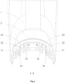
FIG. 6 is a sectional view ofFIG. 5 ; -
FIG. 7 is a partially enlarged view of part A inFIG. 6 ; and -
FIG. 8 is a partially enlarged view of part B inFIG. 6 . - List of reference signs:
- 1: body; 11: positioning opening; 12: contact surface;
- 2: elastic clamping member; 21: positioning hook; 22: reinforcement rib; 23: support structure;
- 3: hanger.
- Preferred embodiments of the present disclosure will be described below with reference to the accompanying drawings. It should be understood by those skilled in the art that these embodiments are only used to explain the technical principles of the present disclosure, and are not intended to limit the scope of protection of the present disclosure.
- It should be noted that in the description of the present disclosure, terms indicating directional or positional relationships, such as "upper", "lower", "left", "right" and the like, are based on the directional or positional relationships shown in the accompanying drawings. They are only used for ease of description, and do not indicate or imply that the device or element must have a specific orientation, or be constructed or operated in a specific orientation, and therefore they should not be considered as limitations to the present disclosure.
- In addition, it should also be noted that in the description of the present disclosure, unless otherwise clearly specified and defined, terms "arrange", "install", "connect" and "connection" should be understood in a broad sense; for example, the connection may be a fixed connection, or may also be a detachable connection, or an integral connection; it may be a mechanical connection, or an electrical connection; it may be a direct connection, or an indirect connection implemented through an intermediate medium, or it may be an internal communication between two elements. For those skilled in the art, the specific meaning of the above terms in the present disclosure can be understood according to specific situations.
- Based on the problem pointed out in the "BACKGROUND OF THE INVENTION" that the hanger may easily fall off the crossbeam of the clothing shaking device during the operation of the existing clothing care apparatus, the present disclosure provides a new crossbeam for a clothing shaking device, a new clothing shaking device and a new clothing care apparatus, aiming at improving the connection stability between the hanger and the crossbeam, and preventing the hanger from falling off the crossbeam during the operation of the clothing care apparatus.
- Specifically, as shown in
FIG. 1 , the crossbeam includes abody 1 and anelastic clamping member 2 provided on thebody 1. Theelastic clamping member 2 is configured to be capable of elastically clamping a hanger 3. As can be known from the background art, since the crossbeam is made of a high-hardness material, the connection between the hanger 3 and the crossbeam is unstable, which causes the hanger 3 to easily fall off the crossbeam during the operation of the clothing care apparatus. For this reason, theelastic clamping member 2 is provided on the crossbeam in the present disclosure, and the hanger 3 is clamped and fixed by theelastic clamping member 2, that is, theelastic clamping member 2 can elastically clamp the hanger 3 through its own elasticity, which can improve the connection stability between the hanger 3 and the crossbeam, and prevent the hanger 3 from falling off the crossbeam during the operation of the clothing care apparatus. Theelastic clamping member 2 is made of a plastic material, which has a certain elasticity and can realize elastic clamping of the hanger 3. Of course, theelastic clamping member 2 may also be made of other elastic materials such as rubber. Such adjustments and changes to the specific manufacturing materials of theelastic clamping member 2 do not deviate from the principle and scope of the present disclosure, and should be defined within the scope of protection of the present disclosure. - Preferably, as shown in
FIGS. 2 to 6 , the crossbeam further includes a positioning member, which can position theelastic clamping member 2 to thebody 1. The positioning member can be configured as a structure in which a positioning hook is matched with a positioning opening, or as a structure in which a snap-fit slot is matched with a snap-fit plate, or as a structure in which a positioning post is matched with a positioning hole, etc. Those skilled in the art may flexibly set the specific structure of the positioning member in practical applications, as long as theelastic clamping member 2 can be positioned to thebody 1 by the positioning member. - In a possible embodiment, the positioning member includes a positioning hook provided on the
body 1 and a positioning opening provided on theelastic clamping member 2, and the positioning hook is matched with the positioning opening. That is, theelastic clamping member 2 is positioned to thebody 1 through the cooperation of the positioning hook and the positioning opening. - In another possible embodiment, as shown in
FIGS. 2 to 6 , the positioning member includes apositioning opening 11 provided on thebody 1 and apositioning hook 21 provided on theelastic clamping member 2. Thepositioning hook 21 is matched with thepositioning opening 11. That is, thepositioning hook 21 cooperates with thepositioning opening 11 to position theelastic clamping member 2 to thebody 1. It should be noted that although the numbers of thepositioning hook 21 and thepositioning opening 11 in the figure are both two, this is not restrictive. The numbers of thepositioning hook 21 and thepositioning opening 11 may also be one, three or four, etc. Such adjustments and changes to the specific numbers of thepositioning hook 21 and thepositioning opening 11 do not deviate from the principle and scope of the present disclosure, and should be defined within the scope of protection of the present disclosure. In addition, it should be noted that the numbers of thepositioning hook 21 and thepositioning opening 11 do not necessarily have to be the same. For example, in the figure, two positioning hooks 21 may be simultaneously snap-fitted in anelongated positioning opening 11. Alternatively, three positioning hooks 21 arranged annularly may be simultaneously snap-fitted in acircular positioning opening 11, etc. Those skilled in the art may flexibly adjust the specific number of thepositioning hook 21 and the specific number of thepositioning opening 11 in practical applications, as long as theelastic clamping member 2 can be positioned to thebody 1 through the cooperation of thepositioning hook 21 and thepositioning opening 11. - Preferably, as shown in
FIG. 3 , in order to improve the strength of thepositioning hook 21, areinforcement rib 22 is provided on thepositioning hook 21. Through such an arrangement, the connection stability between thepositioning hook 21 and thepositioning opening 11 can be improved, so that the connection stability between theelastic clamping member 2 and thebody 1 can be improved. It should be noted that although only onereinforcement rib 22 is provided on one side of thepositioning hook 21 in the figure, this is not restrictive, and areinforcement rib 22 may also be provided on the other side of thepositioning hook 21, or tworeinforcement ribs 22 are provided on one side of thepositioning hook 21, and so on. Such adjustments and changes to the specific arrangement position and specific number of thereinforcement rib 22 do not deviate from the principle and scope of the present disclosure, and should be defined within the scope of protection of the present disclosure. - Preferably, as shown in
FIGS. 3 to 6 , theelastic clamping member 2 is provided with asupport structure 23 on a side facing thebody 1, and after the assembly is completed, thesupport structure 23 elastically abuts against thebody 1 so that thepositioning hook 21 is hooked tightly on thepositioning opening 11. That is, after the assembly is completed, thesupport structure 23 is in a compressed state, so that theelastic clamping member 2 is subjected to a support reaction force, and under the action of the support reaction force, thepositioning hook 21 can be hooked on thepositioning opening 11. Through such an arrangement, theelastic clamping member 2 can be tightly fixed to thebody 1 to avoid swinging of theelastic clamping member 2 relative to thebody 1. Thesupport structure 23 is a support plate formed on theelastic clamping member 2. After the assembly is completed, a bottom of the support plate elastically abuts against thebody 1 so that thepositioning hook 21 is hooked on thepositioning opening 11. Of course, thesupport structure 23 may also be a support column or other structures formed on theelastic clamping member 2. Such adjustments and changes to the specific structure of thesupport structure 23 do not deviate from the principle and scope of the present disclosure, and should be defined within the scope of protection of the present disclosure. - In a possible embodiment, a part (i.e., a contact surface 12) of the
body 1 that is in contact with thesupport structure 23 is a flat surface. After the assembly is completed, thesupport structure 23 is in a compressed state, so that theelastic clamping 2 is subjected to a vertical upward support reaction force, and under the action of the support reaction force, thepositioning hook 21 can be hooked on thepositioning opening 11. - In a preferred embodiment, as shown in
FIG. 5 to FIG. 8 , the part (the contact surface 12) of thebody 1 that is in contact with thesupport structure 23 is inclinedly arranged, and an included angle between the inclined direction and a horizontal plane is between 0 and 90 degrees. First, taking thesupport structure 23 provided on the left side as an example, after the assembly is completed, thesupport structure 23 is in a compressed state, so that theelastic clamping member 2 is subjected to a leftward and upward diagonal support reaction force. Under the action of this support reaction force, thepositioning hook 21 on the left side can be more tightly hooked on thepositioning opening 11; second, taking thesupport structure 23 provided on the right side as an example, after the assembly is completed, thesupport structure 23 is in a compressed state, so that theelastic clamping member 2 is subjected to a rightward and upward diagonal support reaction force, and under the action of this support reaction force, thepositioning hook 21 on the right side can be more tightly hooked on thepositioning opening 11. Obviously, as compared with the above embodiment, thepositioning hook 21 and thepositioning opening 11 are more closely coupled in this preferred embodiment, so that the connection stability between theelastic clamping member 2 and thebody 1 is better. It should be noted that by defining that the included angle between the inclined direction of the part (the contact surface 12) of the body 1 that is in contact with the support structure 23 and the horizontal plane is between 0 and 90 degrees, it means that for the support structure 23 provided on the left side, if the part (the contact surface 12) of the body 1 that is in contact with the support structure 23 is an inclined surface, then the included angle (the angle a shown inFIG. 7 ) between this inclined surface and the horizontal plane is between 0 and 90 degrees, and if the part (the contact surface 12) of the body 1 that is in contact with the support structure 23 is a circular arc surface, then the included angle (the angle a shown inFIG. 7 ) between a tangent direction of the circular arc surface of the body 1 that is in contact with the support structure 23 and the horizontal plane is between 0 and 90 degrees; and for the support structure 23 provided on the right side, if the part (the contact surface 12) of the body 1 that is in contact with the support structure 23 is an inclined surface, then the included angle (the angle b shown inFIG. 8 ) between this inclined surface and the horizontal plane is between 0 and 90 degrees, and if the part (the contact surface 12) of the body 1 that is in contact with the support structure 23 is a circular arc surface, then the included angle (the angle b shown inFIG. 8 ) between a tangent direction of the circular arc surface of the body 1 that is in contact with the support structure 23 and the horizontal plane is between 0 and 90 degrees. - Hitherto, the technical solutions of the present disclosure have been described in conjunction with the preferred embodiments shown in the accompanying drawings, but it is easily understood by those skilled in the art that the scope of protection of the present disclosure is obviously not limited to these specific embodiments. Without departing from the principles of the present disclosure, those skilled in the art can make equivalent changes or replacements to relevant technical features, and all the technical solutions after these changes or replacements will fall within the scope of protection of the present disclosure.
Claims (10)
- A crossbeam for a clothing shaking device, wherein the crossbeam comprises a body and an elastic clamping member arranged on the body, and the elastic clamping member is configured to be capable of elastically clamping a hanger.
- The crossbeam according to claim 1, further comprising a positioning member which is capable of positioning the elastic clamping member to the body.
- The crossbeam according to claim 2, wherein the positioning member comprises a positioning hook provided on the body and a positioning opening provided on the elastic clamping member, and the positioning hook is matched with the positioning opening.
- The crossbeam according to claim 3, wherein the positioning member comprises a positioning opening provided on the body and a positioning hook provided on the elastic clamping member, and the positioning hook is matched with the positioning opening.
- The crossbeam according to claim 4, wherein the positioning hook is provided with a reinforcement rib.
- The crossbeam according to claim 4, wherein the elastic clamping member is provided with a support structure on a side facing the body, and after the assembly is completed, the support structure elastically abuts against the body so that the positioning hook is hooked tightly on the positioning opening.
- The crossbeam according to claim 6, wherein a part of the body that is in contact with the support structure is inclinedly arranged, and an included angle between the inclined direction and a horizontal plane is between 0 and 90 degrees.
- The crossbeam according to any one of claims 1 to 7, wherein the elastic clamping member is made of a plastic material.
- A clothing shaking device, comprising the crossbeam according to any one of claims 1 to 8.
- A clothing care apparatus, comprising the crossbeam according to any one of claims 1 to 8.
Applications Claiming Priority (2)
| Application Number | Priority Date | Filing Date | Title |
|---|---|---|---|
| CN201910195226.4A CN109930348B (en) | 2019-03-14 | 2019-03-14 | Crossbeam for clothing shaking device, clothing shaking device and clothing care equipment |
| PCT/CN2020/077467 WO2020182008A1 (en) | 2019-03-14 | 2020-03-02 | Cross beam for clothing shaking device, clothing shaking device and clothing care equipment |
Publications (4)
| Publication Number | Publication Date |
|---|---|
| EP3940136A1 true EP3940136A1 (en) | 2022-01-19 |
| EP3940136A4 EP3940136A4 (en) | 2022-05-04 |
| EP3940136C0 EP3940136C0 (en) | 2024-08-28 |
| EP3940136B1 EP3940136B1 (en) | 2024-08-28 |
Family
ID=66987267
Family Applications (1)
| Application Number | Title | Priority Date | Filing Date |
|---|---|---|---|
| EP20769109.8A Active EP3940136B1 (en) | 2019-03-14 | 2020-03-02 | Cross beam for clothing shaking device, clothing shaking device and clothing care equipment |
Country Status (6)
| Country | Link |
|---|---|
| US (1) | US11889935B2 (en) |
| EP (1) | EP3940136B1 (en) |
| JP (1) | JP7343605B2 (en) |
| CN (1) | CN109930348B (en) |
| AU (1) | AU2020238418B2 (en) |
| WO (1) | WO2020182008A1 (en) |
Families Citing this family (4)
| Publication number | Priority date | Publication date | Assignee | Title |
|---|---|---|---|---|
| CN109930348B (en) * | 2019-03-14 | 2024-10-22 | 青岛海尔洗衣机有限公司 | Crossbeam for clothing shaking device, clothing shaking device and clothing care equipment |
| CN112176686A (en) | 2019-07-02 | 2021-01-05 | 青岛海尔洗衣机有限公司 | Clothes shaking device for clothing care equipment |
| JP7329398B2 (en) * | 2019-09-13 | 2023-08-18 | 理研軽金属工業株式会社 | Portable bicycle parking device for bicycles |
| JP2025184628A (en) * | 2024-06-07 | 2025-12-18 | 美優 青木 | Hanger holder |
Family Cites Families (28)
| Publication number | Priority date | Publication date | Assignee | Title |
|---|---|---|---|---|
| JPS5632233Y2 (en) * | 1977-09-10 | 1981-07-31 | ||
| US4960213A (en) * | 1989-04-14 | 1990-10-02 | Armstrong Store Fixture Coporation | Hanger support guard |
| US5139298A (en) * | 1991-08-20 | 1992-08-18 | Dowell Richard E | Binder for hanger-mounted garments |
| GB2349909A (en) * | 1999-04-10 | 2000-11-15 | Mainetti | Attachment for a garment hanger |
| US7097051B2 (en) * | 2003-08-15 | 2006-08-29 | Maytag Corporation | Hanger rod for drying cabinet |
| JP2005102982A (en) | 2003-09-30 | 2005-04-21 | Yoshino Kogyosho Co Ltd | Cosmetic container |
| US7404502B2 (en) * | 2004-02-05 | 2008-07-29 | The Build-Up Plastics & Metal Co., Ltd. | Hanger assembly and a hanger formed of such an assembly |
| US7137211B2 (en) * | 2004-08-18 | 2006-11-21 | Maytag Corporation | Drying cabinet shaker mechanism |
| TWM291263U (en) * | 2005-08-26 | 2006-06-01 | Raymond Wu | Clip structure of clothes hanger |
| CN201473779U (en) * | 2009-08-11 | 2010-05-19 | 南京乐金熊猫电器有限公司 | Front panel of impeller washing machine |
| JP5821048B2 (en) | 2011-03-18 | 2015-11-24 | 株式会社ニックス | Clamping tool |
| KR102217534B1 (en) * | 2014-01-28 | 2021-02-18 | 엘지전자 주식회사 | Washing machine and control method thereof |
| US9445679B2 (en) * | 2014-09-26 | 2016-09-20 | Hangers Plus, Llc | Hanger |
| JP6611504B2 (en) | 2015-07-30 | 2019-11-27 | キヤノン株式会社 | Cable holding structure and image forming apparatus |
| CN105390869B (en) * | 2015-12-16 | 2019-03-01 | 上海电科电器科技有限公司 | The plug locking system of surge protector |
| CN205934500U (en) * | 2016-08-22 | 2017-02-08 | 安吉印象家具有限公司 | Clothes hanger |
| CN205934499U (en) * | 2016-08-22 | 2017-02-08 | 安吉印象家具有限公司 | But wall -hanging telescopic laundry rack |
| CN206141418U (en) * | 2016-10-09 | 2017-05-03 | 武汉通畅汽车电子照明有限公司 | Circle is decorated to anticreep buckle structure and anticreep car car light |
| CN207033324U (en) * | 2017-07-25 | 2018-02-23 | 浙江亿达建设有限公司 | A kind of step ladder for house ornamentation |
| TWM553970U (en) * | 2017-08-11 | 2018-01-11 | Zhu Fu Quan | Clothes hanger assembly |
| CN208087942U (en) * | 2018-03-12 | 2018-11-13 | 青岛海思科科技有限公司 | A kind of laundry care cabinet |
| CN208072036U (en) * | 2018-03-29 | 2018-11-09 | 安徽师范大学 | A kind of clothing jittering device |
| CN208562900U (en) * | 2018-04-12 | 2019-03-01 | 广州方硅信息技术有限公司 | A kind of intelligent Outdoor clothes airing rack |
| CN208440858U (en) * | 2018-05-04 | 2019-01-29 | 青岛海尔洗衣机有限公司 | Shaking device and laundry treatment device for laundry |
| CN108708140A (en) * | 2018-06-06 | 2018-10-26 | 湖州三杰服饰有限公司 | A kind of drying device dried for children's garment |
| CN108842398A (en) * | 2018-09-07 | 2018-11-20 | 李成锦 | A kind of multi-functional automatic airer |
| CN210117528U (en) * | 2019-03-14 | 2020-02-28 | 青岛海尔洗衣机有限公司 | Beam for laundry shaker, laundry shaker and laundry care equipment |
| CN109930348B (en) * | 2019-03-14 | 2024-10-22 | 青岛海尔洗衣机有限公司 | Crossbeam for clothing shaking device, clothing shaking device and clothing care equipment |
-
2019
- 2019-03-14 CN CN201910195226.4A patent/CN109930348B/en active Active
-
2020
- 2020-03-02 JP JP2021552195A patent/JP7343605B2/en active Active
- 2020-03-02 EP EP20769109.8A patent/EP3940136B1/en active Active
- 2020-03-02 AU AU2020238418A patent/AU2020238418B2/en active Active
- 2020-03-02 WO PCT/CN2020/077467 patent/WO2020182008A1/en not_active Ceased
- 2020-03-02 US US17/439,041 patent/US11889935B2/en active Active
Also Published As
| Publication number | Publication date |
|---|---|
| CN109930348A (en) | 2019-06-25 |
| US11889935B2 (en) | 2024-02-06 |
| JP2022522850A (en) | 2022-04-20 |
| AU2020238418A1 (en) | 2021-10-14 |
| JP7343605B2 (en) | 2023-09-12 |
| EP3940136A4 (en) | 2022-05-04 |
| CN109930348B (en) | 2024-10-22 |
| AU2020238418B2 (en) | 2023-04-13 |
| WO2020182008A1 (en) | 2020-09-17 |
| US20220151415A1 (en) | 2022-05-19 |
| EP3940136C0 (en) | 2024-08-28 |
| EP3940136B1 (en) | 2024-08-28 |
Similar Documents
| Publication | Publication Date | Title |
|---|---|---|
| US11889935B2 (en) | Cross beam for clothing shaking device, clothing shaking device and clothing care equipment | |
| US8246023B2 (en) | Vibration damper, particularly for supporting compressors, pumps, electric motors and the like | |
| US20180297071A1 (en) | Linear vibration motor | |
| WO2020200259A1 (en) | Clothing shaking device for clothing care apparatus, and clothing care apparatus | |
| CN102918279B (en) | ceiling fan | |
| CN108698209A (en) | A positioning fixture and assembly equipment | |
| CN106486811A (en) | Electroconductive elastic sheet and the electronic equipment being provided with this electroconductive elastic sheet | |
| CN110165435A (en) | A kind of electric connecting clamp | |
| CN210117528U (en) | Beam for laundry shaker, laundry shaker and laundry care equipment | |
| CN212505485U (en) | Handle and clothes treatment equipment | |
| EP3389246B1 (en) | Card holder apparatus used for mounting telephone card, and mobile device | |
| CN112490052B (en) | Multi-directional input device | |
| CN204810809U (en) | Electronic component's holder | |
| WO2019085202A1 (en) | Connection assembly | |
| CN214883788U (en) | Rigidity adjusting device | |
| CN104077970A (en) | Motion combined mechanism applied to pre-maintenance LED (Light-Emitting Diode) | |
| CN216752491U (en) | Circuit board support piece, control panel and household appliance | |
| CN212874357U (en) | Transmission mechanism and DC contactor for contactor | |
| CN204199047U (en) | Laundry drum thermomechanical components | |
| CN216957884U (en) | Stable form temperature controller switch | |
| CN208689313U (en) | A fixed structure of a concentrator liquid crystal support | |
| CN208004587U (en) | Punch fixed structure and punch-head assembly with it | |
| CN105581676B (en) | A kind of mixer | |
| CN216699003U (en) | Carbon brush assembly convenient for replacing carbon brush | |
| CN215260190U (en) | Air conditioner outdoor unit and air conditioner |
Legal Events
| Date | Code | Title | Description |
|---|---|---|---|
| STAA | Information on the status of an ep patent application or granted ep patent |
Free format text: STATUS: THE INTERNATIONAL PUBLICATION HAS BEEN MADE |
|
| PUAI | Public reference made under article 153(3) epc to a published international application that has entered the european phase |
Free format text: ORIGINAL CODE: 0009012 |
|
| STAA | Information on the status of an ep patent application or granted ep patent |
Free format text: STATUS: REQUEST FOR EXAMINATION WAS MADE |
|
| 17P | Request for examination filed |
Effective date: 20210928 |
|
| AK | Designated contracting states |
Kind code of ref document: A1 Designated state(s): AL AT BE BG CH CY CZ DE DK EE ES FI FR GB GR HR HU IE IS IT LI LT LU LV MC MK MT NL NO PL PT RO RS SE SI SK SM TR |
|
| A4 | Supplementary search report drawn up and despatched |
Effective date: 20220407 |
|
| RIC1 | Information provided on ipc code assigned before grant |
Ipc: F16B 2/22 20060101ALN20220401BHEP Ipc: D06F 57/12 20060101AFI20220401BHEP |
|
| DAV | Request for validation of the european patent (deleted) | ||
| DAX | Request for extension of the european patent (deleted) | ||
| REG | Reference to a national code |
Ref country code: DE Ref legal event code: R079 Free format text: PREVIOUS MAIN CLASS: D06F0058200000 Ipc: D06F0057120000 Ref country code: DE Ref legal event code: R079 Ref document number: 602020036718 Country of ref document: DE Free format text: PREVIOUS MAIN CLASS: D06F0058200000 Ipc: D06F0057120000 |
|
| GRAP | Despatch of communication of intention to grant a patent |
Free format text: ORIGINAL CODE: EPIDOSNIGR1 |
|
| STAA | Information on the status of an ep patent application or granted ep patent |
Free format text: STATUS: GRANT OF PATENT IS INTENDED |
|
| RIC1 | Information provided on ipc code assigned before grant |
Ipc: F16B 2/22 20060101ALN20240222BHEP Ipc: D06F 57/12 20060101AFI20240222BHEP |
|
| RIC1 | Information provided on ipc code assigned before grant |
Ipc: F16B 2/22 20060101ALN20240304BHEP Ipc: D06F 57/12 20060101AFI20240304BHEP |
|
| INTG | Intention to grant announced |
Effective date: 20240322 |
|
| GRAS | Grant fee paid |
Free format text: ORIGINAL CODE: EPIDOSNIGR3 |
|
| GRAA | (expected) grant |
Free format text: ORIGINAL CODE: 0009210 |
|
| STAA | Information on the status of an ep patent application or granted ep patent |
Free format text: STATUS: THE PATENT HAS BEEN GRANTED |
|
| AK | Designated contracting states |
Kind code of ref document: B1 Designated state(s): AL AT BE BG CH CY CZ DE DK EE ES FI FR GB GR HR HU IE IS IT LI LT LU LV MC MK MT NL NO PL PT RO RS SE SI SK SM TR |
|
| REG | Reference to a national code |
Ref country code: CH Ref legal event code: EP |
|
| REG | Reference to a national code |
Ref country code: DE Ref legal event code: R096 Ref document number: 602020036718 Country of ref document: DE |
|
| REG | Reference to a national code |
Ref country code: IE Ref legal event code: FG4D |
|
| U01 | Request for unitary effect filed |
Effective date: 20240923 |
|
| U07 | Unitary effect registered |
Designated state(s): AT BE BG DE DK EE FI FR IT LT LU LV MT NL PT RO SE SI Effective date: 20241015 |
|
| PG25 | Lapsed in a contracting state [announced via postgrant information from national office to epo] |
Ref country code: NO Free format text: LAPSE BECAUSE OF FAILURE TO SUBMIT A TRANSLATION OF THE DESCRIPTION OR TO PAY THE FEE WITHIN THE PRESCRIBED TIME-LIMIT Effective date: 20241128 |
|
| PG25 | Lapsed in a contracting state [announced via postgrant information from national office to epo] |
Ref country code: PL Free format text: LAPSE BECAUSE OF FAILURE TO SUBMIT A TRANSLATION OF THE DESCRIPTION OR TO PAY THE FEE WITHIN THE PRESCRIBED TIME-LIMIT Effective date: 20240828 Ref country code: GR Free format text: LAPSE BECAUSE OF FAILURE TO SUBMIT A TRANSLATION OF THE DESCRIPTION OR TO PAY THE FEE WITHIN THE PRESCRIBED TIME-LIMIT Effective date: 20241129 |
|
| PG25 | Lapsed in a contracting state [announced via postgrant information from national office to epo] |
Ref country code: IS Free format text: LAPSE BECAUSE OF FAILURE TO SUBMIT A TRANSLATION OF THE DESCRIPTION OR TO PAY THE FEE WITHIN THE PRESCRIBED TIME-LIMIT Effective date: 20241228 |
|
| PG25 | Lapsed in a contracting state [announced via postgrant information from national office to epo] |
Ref country code: HR Free format text: LAPSE BECAUSE OF FAILURE TO SUBMIT A TRANSLATION OF THE DESCRIPTION OR TO PAY THE FEE WITHIN THE PRESCRIBED TIME-LIMIT Effective date: 20240828 |
|
| PG25 | Lapsed in a contracting state [announced via postgrant information from national office to epo] |
Ref country code: RS Free format text: LAPSE BECAUSE OF FAILURE TO SUBMIT A TRANSLATION OF THE DESCRIPTION OR TO PAY THE FEE WITHIN THE PRESCRIBED TIME-LIMIT Effective date: 20241128 Ref country code: ES Free format text: LAPSE BECAUSE OF FAILURE TO SUBMIT A TRANSLATION OF THE DESCRIPTION OR TO PAY THE FEE WITHIN THE PRESCRIBED TIME-LIMIT Effective date: 20240828 |
|
| PG25 | Lapsed in a contracting state [announced via postgrant information from national office to epo] |
Ref country code: RS Free format text: LAPSE BECAUSE OF FAILURE TO SUBMIT A TRANSLATION OF THE DESCRIPTION OR TO PAY THE FEE WITHIN THE PRESCRIBED TIME-LIMIT Effective date: 20241128 Ref country code: PL Free format text: LAPSE BECAUSE OF FAILURE TO SUBMIT A TRANSLATION OF THE DESCRIPTION OR TO PAY THE FEE WITHIN THE PRESCRIBED TIME-LIMIT Effective date: 20240828 Ref country code: NO Free format text: LAPSE BECAUSE OF FAILURE TO SUBMIT A TRANSLATION OF THE DESCRIPTION OR TO PAY THE FEE WITHIN THE PRESCRIBED TIME-LIMIT Effective date: 20241128 Ref country code: IS Free format text: LAPSE BECAUSE OF FAILURE TO SUBMIT A TRANSLATION OF THE DESCRIPTION OR TO PAY THE FEE WITHIN THE PRESCRIBED TIME-LIMIT Effective date: 20241228 Ref country code: HR Free format text: LAPSE BECAUSE OF FAILURE TO SUBMIT A TRANSLATION OF THE DESCRIPTION OR TO PAY THE FEE WITHIN THE PRESCRIBED TIME-LIMIT Effective date: 20240828 Ref country code: GR Free format text: LAPSE BECAUSE OF FAILURE TO SUBMIT A TRANSLATION OF THE DESCRIPTION OR TO PAY THE FEE WITHIN THE PRESCRIBED TIME-LIMIT Effective date: 20241129 Ref country code: ES Free format text: LAPSE BECAUSE OF FAILURE TO SUBMIT A TRANSLATION OF THE DESCRIPTION OR TO PAY THE FEE WITHIN THE PRESCRIBED TIME-LIMIT Effective date: 20240828 |
|
| U20 | Renewal fee for the european patent with unitary effect paid |
Year of fee payment: 6 Effective date: 20250225 |
|
| PG25 | Lapsed in a contracting state [announced via postgrant information from national office to epo] |
Ref country code: SM Free format text: LAPSE BECAUSE OF FAILURE TO SUBMIT A TRANSLATION OF THE DESCRIPTION OR TO PAY THE FEE WITHIN THE PRESCRIBED TIME-LIMIT Effective date: 20240828 |
|
| PG25 | Lapsed in a contracting state [announced via postgrant information from national office to epo] |
Ref country code: CZ Free format text: LAPSE BECAUSE OF FAILURE TO SUBMIT A TRANSLATION OF THE DESCRIPTION OR TO PAY THE FEE WITHIN THE PRESCRIBED TIME-LIMIT Effective date: 20240828 |
|
| PG25 | Lapsed in a contracting state [announced via postgrant information from national office to epo] |
Ref country code: SK Free format text: LAPSE BECAUSE OF FAILURE TO SUBMIT A TRANSLATION OF THE DESCRIPTION OR TO PAY THE FEE WITHIN THE PRESCRIBED TIME-LIMIT Effective date: 20240828 |
|
| PLBE | No opposition filed within time limit |
Free format text: ORIGINAL CODE: 0009261 |
|
| STAA | Information on the status of an ep patent application or granted ep patent |
Free format text: STATUS: NO OPPOSITION FILED WITHIN TIME LIMIT |
|
| 26N | No opposition filed |
Effective date: 20250530 |
|
| PG25 | Lapsed in a contracting state [announced via postgrant information from national office to epo] |
Ref country code: MC Free format text: LAPSE BECAUSE OF FAILURE TO SUBMIT A TRANSLATION OF THE DESCRIPTION OR TO PAY THE FEE WITHIN THE PRESCRIBED TIME-LIMIT Effective date: 20240828 |
|
| REG | Reference to a national code |
Ref country code: CH Ref legal event code: H13 Free format text: ST27 STATUS EVENT CODE: U-0-0-H10-H13 (AS PROVIDED BY THE NATIONAL OFFICE) Effective date: 20251023 |
|
| GBPC | Gb: european patent ceased through non-payment of renewal fee |
Effective date: 20250302 |
|
| PG25 | Lapsed in a contracting state [announced via postgrant information from national office to epo] |
Ref country code: GB Free format text: LAPSE BECAUSE OF NON-PAYMENT OF DUE FEES Effective date: 20250302 |
|
| PG25 | Lapsed in a contracting state [announced via postgrant information from national office to epo] |
Ref country code: CH Free format text: LAPSE BECAUSE OF NON-PAYMENT OF DUE FEES Effective date: 20250331 |
|
| PG25 | Lapsed in a contracting state [announced via postgrant information from national office to epo] |
Ref country code: IE Free format text: LAPSE BECAUSE OF NON-PAYMENT OF DUE FEES Effective date: 20250302 |
|
| U20 | Renewal fee for the european patent with unitary effect paid |
Year of fee payment: 7 Effective date: 20260326 |