EP3939884B1 - Ermittlung des beladungszustandes eines stauraumes auf basis eines akustischen resonanzverhaltens - Google Patents
Ermittlung des beladungszustandes eines stauraumes auf basis eines akustischen resonanzverhaltens Download PDFInfo
- Publication number
- EP3939884B1 EP3939884B1 EP21184558.1A EP21184558A EP3939884B1 EP 3939884 B1 EP3939884 B1 EP 3939884B1 EP 21184558 A EP21184558 A EP 21184558A EP 3939884 B1 EP3939884 B1 EP 3939884B1
- Authority
- EP
- European Patent Office
- Prior art keywords
- storage space
- storage compartment
- storage
- objects
- excitation
- Prior art date
- Legal status (The legal status is an assumption and is not a legal conclusion. Google has not performed a legal analysis and makes no representation as to the accuracy of the status listed.)
- Active
Links
Images


Classifications
-
- B—PERFORMING OPERATIONS; TRANSPORTING
- B64—AIRCRAFT; AVIATION; COSMONAUTICS
- B64D—EQUIPMENT FOR FITTING IN OR TO AIRCRAFT; FLIGHT SUITS; PARACHUTES; ARRANGEMENT OR MOUNTING OF POWER PLANTS OR PROPULSION TRANSMISSIONS IN AIRCRAFT
- B64D11/00—Passenger or crew accommodation; Flight-deck installations not otherwise provided for
- B64D11/003—Stowage devices for passengers' personal luggage
Definitions
- the invention relates to a storage compartment for an aircraft and the loading condition of the storage space of the storage compartment with objects.
- storage compartments in the form of luggage compartments are usually arranged above the rows of seats for the passengers, in order to accommodate objects, e.g. in the form of the passengers' luggage.
- Various systems are known for determining or monitoring an occupancy rate/status of luggage compartments or stowage spaces.
- cameras such as TOF cameras (TOF: time of flight) can be used to record the storage space of the overhead compartment.
- TOF time of flight
- such systems can be used to monitor or control the luggage compartments, for example in order to determine an available storage space in the luggage compartments.
- the reference discloses US2019233113A1 a system for managing a storage space for overhead containers in a vehicle, the system having a set of sensors which are designed to record data and transmit information relating to an overhead storage compartment, the set of sensors comprising at least one camera and a distance measuring device.
- the system further includes a dongle configured to receive the information and to compare the received information to stored data points previously measured when the overhead compartment space was known to be empty and to have a shape and volume of the remaining space in the overhead bin by calculating a difference between the information received and the stored data points.
- the dongle is configured to report a status of the overhead bin based on the shape and volume of the remaining overhead bin space, the status including an empty condition, a partially filled condition, and/or a full condition.
- U.S. 2017/283086 A1 describes a storage compartment arrangement for an aircraft.
- the subject matter of the invention is a storage compartment arrangement which is designed and/or suitable for an aircraft.
- the storage compartment arrangement has at least one, in particular a plurality of storage compartments.
- the storage compartment is preferably designed as an overhead luggage compartment, also known as what is known as an “overhead stowage compartment (OHSC)”.
- OHSC overhead stowage compartment
- the storage compartment can be designed as a rigid storage compartment, also known as a so-called "fixed bin”, or as a pivotable storage compartment, also known as a so-called “movable bin”.
- the stowage compartment can also be designed as any other compartment for stowing objects in an aircraft, such as a so-called "doghouse”.
- the storage compartment has a storage space which is designed and/or suitable for accommodating objects, for example pieces of luggage.
- the storage space is a delimited and (in a closed position of the storage compartment) closed space in which the objects are accommodated during a flight. Objects are loaded/unloaded when the storage compartment is in an open position.
- the storage compartment can have exactly one storage space. Alternatively, however, the storage compartment can also have at least one, in particular a plurality of storage spaces that are separated from one another. Each of the storage spaces then forms a closed space in the closed position. These closed spaces each have an acoustic resonance behavior.
- the storage compartment arrangement has a monitoring system which is designed to determine or monitor a load status of the storage space.
- the monitoring system has the function of recognizing free storage spaces (available space for objects) during a boarding process and/or objects that have been left in the storage space during a deboarding process.
- the monitoring system has a sensor device and an evaluation device, the evaluation device being designed to evaluate the sensor data supplied by the sensor device.
- a separate sensor device is preferably assigned to each of the storage spaces.
- the sensor device and the evaluation device are connected to one another in terms of data technology, in particular by cable or wirelessly, for example via radio, for the transmission of the sensor data supplied by the sensor device.
- the storage compartment has an acoustic resonance behavior that is dependent on the loading state with objects.
- the resonance behavior thus represents in particular an acoustic transfer function (amplitude amplification/phase change over the frequency) of the storage compartment/storage space for an acoustic signal.
- resonance behavior is also understood to mean a spectral acoustic transfer function of the storage compartment.
- An acoustic signal radiated into the storage compartment is possibly changed by the transfer function, so that the changed acoustic signal is set in the storage compartment.
- frequency shifts, amplitude changes or phase changes in the acoustic spectrum of the acoustic signal occur, which are therefore typical of specific load states and types of objects that are located in the storage space.
- a reference transfer function of the storage compartment is first determined when the loading status is known (in particular “empty”).
- Conceivable simple solutions for load states are: “empty” or “not empty” / “empty” or “partly full” or “full”
- more complex solutions are: “full to X %” / "load: X trolleys and Y Garments” / "X liters of storage space available” / “Remaining space for X trolleys or Y garments” etc.
- the storage compartment thus forms a resonator that can be excited by an acoustic signal.
- the storage compartment forms a closed acoustic resonator in the closed position.
- the resonator can preferably be excited by sound waves as the acoustic signals.
- the sensor device has at least one, in particular a plurality of acoustic sensors, which are designed to detect and/or also detect the acoustic signal within the storage space.
- the acoustic sensor is integrated into a wall of the storage compartment or storage space and/or is arranged at least partially within the storage space.
- the sensor device is designed to output sensor data that is correlated to the acoustic signal.
- the acoustic signal is output in the form of an electrical oscillation as sensor data. Alternatively, a frequency spectrum or spectral values of the acoustic signal are output, etc.
- the evaluation device is designed to determine the current resonance behavior, in particular in the form of a frequency spectrum of the recorded signal, of the storage compartment using the sensor data. Furthermore, it is designed to determine the load status of the storage space with objects on the basis of the determined resonance behavior.
- the storage compartment as an acoustic resonator is thus stimulated to oscillate in particular by the radiation of an acoustic signal into the storage space, the storage compartment having a first characteristic, design-related resonance behavior depending on the loading with objects, eg in an empty loading state.
- the resonator properties, ie the resonance behavior, of the storage compartment change, so that this can be detected as a change in the resonance behavior.
- the evaluation device is preferably designed to determine different loading states on the basis of different resonance behavior. The different resonance behavior thus generates a respective different acoustic "output signal" (signal that occurs in the storage space) in response to the irradiation of an acoustic input/excitation signal.
- the storage compartment as a resonator thus represents a system, with the output signal, ie the acoustic signal prevailing in the storage compartment, forming the system response to the input signal.
- the system is changed by the loading condition with objects, so the system response and thus the output signal as well is also changed.
- the evaluation device is designed to determine the loading state based on an analysis of room modes in the resonator. In particular, by considering the modal behavior of the storage compartment, conclusions can be drawn about the loading state of the storage space.
- a monitoring system which enables information regarding the load status based on the resonance or the current acoustic resonance behavior.
- the advantage of the invention consists in particular in the fact that the loading status of the storage compartment can be represented in a simple manner with the aid of acoustic parameters.
- objects in the storage space can be detected efficiently and the loading status of the storage compartment can be determined.
- the acoustic detection of the load state suggests a sensor device which is characterized by a small number of sensor components. A component-reduced and cost-effective monitoring system can thus be created.
- the evaluation device is designed to determine an available volume of the storage space on the basis of the current resonance behavior.
- the evaluation device is designed to detect one or more objects arranged in the storage space on the basis of the resonance behavior.
- the evaluation device is preferably designed to determine the volume of the storage space or the objects on the basis of a change in phase and/or frequency and/or amplitude of the detected resonance behavior (spectrum).
- the evaluation device is designed to infer and/or identify one or more objects and/or free storage spaces in the storage space based on a change in the antinodes and/or the vibration nodes in the acoustic signal on the resonance behavior.
- An acoustic model can optionally be stored in the evaluation device, in which sound-emitting, in particular sound-absorbing, sound-reflecting, sound-deflecting and/or sound-attenuating objects are recorded, so that a distinction can be made between different objects in the storage space on the basis of the change in the resonance behavior.
- a property for example a distinction between comparatively hard (trolleys) and soft objects (clothing), can be taken into account when determining the load status.
- At least one, in particular several or all, of the acoustic sensors is designed as a microphone, the microphone being at least partially arranged in the storage space and/or directed into the storage space.
- the microphone is integrated into a side panel or a top panel of the storage compartment.
- the microphone preferably has a directional characteristic which is directed completely or at least for the most part into the storage space.
- An acoustic sensor is thus proposed which is characterized by a cost-effective design.
- the microphone can be integrated into the storage compartment to save space.
- At least one of the acoustic sensors can also be designed as an acceleration sensor, which is designed to detect the acoustic waves of the acoustic signal.
- the acceleration sensor can be arranged on the storage compartment and/or in the storage space.
- the acceleration sensor is designed as a piezoelectric acceleration sensor in order to generate an electrical signal based on a pressure fluctuation triggered by the acoustic wave.
- the sensor device has several acoustic sensors designed as microphones or alternatively as acceleration sensors for detecting the acoustic signals at several different locations of the storage space.
- the multiple acoustic sensors are spatially evenly distributed in the storage space and/or arranged at a distance from one another.
- the several acoustic sensors are connected to the evaluation device in terms of data technology, the evaluation device being designed to evaluate the sensor data recorded by the several acoustic sensors and to correlate them with one another.
- a monitoring system is thus proposed which is characterized by a particularly precise and robust sensor system.
- ambient sound radiates into the storage space in order to form or generate the acoustic signal in the storage space.
- the determination method for the loading state is carried out "passively" using the irradiation of ambient noise that is present anyway.
- the ambient noise serves to excite the storage compartment or storage space as a sound body.
- a specific ambient sound can be characterized by a sound pattern stored in the evaluation device, so that an excitation by the ambient sound through the Evaluation device is detected when the sound pattern is detected.
- the ambient sound is or contains a known, characteristic sound pattern, e.g.
- the closing noise of the storage compartment whose load status is to be detected or an operating noise of a device in the aircraft e.g. a ventilation system, a turbine, engine, etc.
- a device in the aircraft e.g. a ventilation system, a turbine, engine, etc.
- the ambient sound or a part of the ambient noise that is relevant for determining the load status i.e. generated by a closing noise when the storage compartment is closed and/or an operating noise from a ventilation/air conditioning system/turbine/motor.
- a passive monitoring system is thus proposed which is characterized by particularly simple and inexpensive equipment.
- the storage compartment arrangement has an excitation device for reproducing or also generating an excitation sound.
- the excitation sound (changed as a result by the resonance) then forms at least part of the acoustic signal in the storage space.
- the excitation device is preferably formed by one or more loudspeakers.
- the excitation device can also be in the form of a voice coil, also known as an “exciter”, which emits the acoustic signal as an oscillation onto the storage compartment.
- the excitation device can be integrated into the storage compartment or at least arranged in the immediate vicinity of the storage compartment.
- the loudspeaker can be integrated into a passenger service unit of the aircraft, also known as a "passenger service unit” (PSU).
- PSU passenger service unit
- the loudspeaker is preferably a loudspeaker installed as standard, i.e. already in the aircraft anyway, which is designed to play back announcements, safety instructions, etc. and is also misused in this regard for the method of determining the load status or is given an additional or double functionality.
- the excitation sound reproduced by the excitation device can be formed by an actively generated noise, tone, etc.
- the acoustic sensor is designed to pick up the acoustic signal (which occurs) and to pass it on to the evaluation device in the form of the sensor data in order to determine the load status.
- the evaluation device knows the excitation sound reproduced by the excitation device or its characteristics (eg frequency spectrum, amplitude, time course, tone sequence, etc.) and/or is stored in the evaluation device. It thus becomes an "active" Proposed sensor device, which is characterized by an accurate determination of the load status regardless of the environment.
- the evaluation device is connected to the excitation device in terms of transmission technology in order to transmit a control signal to the excitation device.
- the excitation device can be activated by the evaluation device on the basis of the control signal in order to reproduce an excitation sound known to the evaluation device.
- the evaluation device is connected to the excitation device in terms of transmission technology in order to receive playback information from the excitation device.
- the reproduction information includes information about the reproduced excitation sound or its characteristics, by means of which the excitation sound can be clearly identified.
- a known component (proportion generated by the excitation sound) in the acoustic signal can be distinguished from, for example (the resulting signal from) unknown ambient noise.
- the excitation device can optionally be designed for active noise compensation, also known as “active noise cancellation”.
- active noise cancellation an ambient sound to be suppressed can be recorded by the acoustic sensor and a sound with opposite polarity, also called “anti-sound”, can be reproduced by the excitation device in order to eliminate the ambient sound to be suppressed by means of destructive interference.
- the excitation device is designed to emit at least part or all of the excitation sound in the audio frequency range or to radiate it into the storage space.
- the excitation sound is in a frequency range between 75 Hz and 1000 Hz, preferably between 300 Hz and 850 Hz. Since the excitation frequency is in the audible range, an intensive sound design is optionally possible or even recommended or necessary.
- an appropriate ambient or excitation sound may be provided by an audible alarm tone, ringing tone, or the like.
- the closing noise of the storage compartment can also serve as excitation sound.
- a closing mechanism of the storage compartment can be designed to generate a closing noise, which can be evaluated by the evaluation device is suitable and/or optimized.
- the locking mechanism can produce an intense "click" sound for this purpose.
- the evaluation device has a KI module which is designed to learn and/or improve the determination of the load status of the storage space based on the recorded acoustic signal and/or the determined resonance behavior.
- the AI module is designed to determine a current load status of the storage compartment on the basis of the currently detected acoustic signal and/or the determined resonance behavior, in particular as a function of the nature of the individual objects.
- the AI module is preferably designed to process and evaluate the sensor data using a neural network.
- the AI module is designed to learn how to determine a distribution of the objects in the storage space on the basis of the sensor data and/or to improve such a determination. In this way, the boarding and deboarding process can be improved or accelerated.
- the monitoring system has a display device.
- the display device can be formed by a mobile terminal device or a display installed in the aircraft, e.g. a display.
- the display device is connected to the evaluation device in terms of data technology, with the evaluation device being designed to activate the display device as a function of the load status.
- the display device is designed to display the current load status of the storage compartment—in particular during a boarding process and/or during a deboarding process.
- the display device is preferably designed to display the number of free storage spaces and/or an empty or full loading status of the individual storage compartments.
- a monitoring system is thus proposed which is characterized by a precise display of the current load status.
- the aircraft is designed as a passenger aircraft.
- the aircraft has a passenger cabin, with the storage compartment arrangement being arranged in the passenger cabin.
- the storage compartment arrangement is preferably arranged in an overhead area of the passenger cabin.
- the storage compartment arrangement has a plurality of storage compartments, the plurality of storage compartments being arranged one behind the other in the longitudinal direction of the aircraft and forming one or more rows of storage compartments.
- the aircraft preferably has a row of storage compartments for each row of seats.
- Each storage compartment is preferably one assigned separate sensor device, so that the loading status of the individual storage compartments can be detected independently.
- the storage compartment arrangement can also be arranged in a floor or wall area of the passenger cabin.
- the acoustic signal can be generated passively by ambient noise, in particular the noise of the storage compartment closing.
- the acoustic signal (at least a portion thereof) is preferably recorded by the acoustic sensor, in particular the at least one microphone or the at least one acceleration sensor, when the storage compartment is being closed and/or in the closed state.
- the acoustic signal (at least a portion of it) can be generated actively by the above-mentioned excitation device, in particular the loudspeaker or the voice coil.
- the excitation device can, for example, play back the excitation sound at fixed time intervals or by triggering it manually.
- the evaluation device mentioned above can also control the excitation device in order to reproduce the excitation sound.
- the resonance behavior of the storage compartment/storage space changes when at least one object is present in the storage space, wherein the object can be detected and/or identified based on a change in the resonance behavior.
- the loading condition is then determined based on a change in resonance behavior starting from a storage space with known resonance behavior resulting from a known loading condition.
- a "reference" resonance behavior is determined which prevails in a known loading state (in particular an empty storage compartment). From changes in a resonance behavior, which is determined later, the subsequent loading state is then inferred.
- Eg can off a changed phase information in the spectrum of the acoustic signal (compared to the reference spectrum or its reference phase) to the presence of damping objects such as clothing.
- the resonance behavior can change in such a way that the acoustic signal is damped and/or reflected and/or deflected and/or absorbed by the object becomes.
- the objects can also be identified in order to be able to precisely determine the load status.
- a change in the amplitude and/or frequency and/or phase behavior as resonance behavior is used to determine whether solid (i.e. essentially sound-reflecting) or soft (i.e. essentially sound-damping) objects are in the storage space are available.
- solid (i.e. essentially sound-reflecting) or soft (i.e. essentially sound-damping) objects are in the storage space are available.
- a soft object is present in the storage space in the resonance behavior.
- soft objects are to be understood as compressible objects and hard objects as non-compressible or less compressible objects.
- the soft objects have a lower density than the hard objects.
- objects with different properties can thus be recognized.
- a piece of luggage can thus be distinguished from a piece of clothing as an object.
- an available storage space can be determined depending on the distribution of solid and soft objects.
- the current load status can preferably be displayed precisely by evaluating the stowed objects.
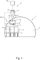
- figure 1 1 shows an interior 2 of an aircraft 1 in a highly schematic view.
- the aircraft 1 is a passenger aircraft, with the interior 2 being designed as a passenger cabin.
- a plurality of seats 3 are arranged next to one another in the interior 2 and form one of a plurality of seat rows 4 with respect to the longitudinal direction of the aircraft.
- only one row of seats 4 is shown, with the seats 3 in principle being able to be grouped as desired in different arrangements and rows of seats.
- a storage compartment arrangement 5 is arranged in the passenger cabin, which has a plurality of storage compartments 6, also known as “bins”, arranged one behind the other in the direction of flight.
- the storage compartments 6 each have a storage space 7, which is used to hold objects 8, e.g. pieces of luggage such as hand luggage, trolley, clothing, backpack, etc. (only indicated here in its entirety by dashed lines).
- a separate storage compartment 5 is assigned to each row of seats 4 .
- Exactly one storage space section of the storage space 7 is assigned to each seat 3 .
- the storage compartments 6 are closed in a closed position G (of a front flap that is not explained in more detail), so that a closed storage space 7 results, i.e. one completely surrounded by walls.
- the front flap shown in dashed lines
- the storage compartment is open, so that one or more objects 8 can be placed or removed in the storage space 7, which is now open to one side.
- the aircraft 1 has a monitoring system 9, with the monitoring system 9 having the function of determining a load status B1,2 of the storage spaces 7 of the individual storage compartments 6.
- the monitoring system 9 has a sensor device 10 which is used to detect an acoustic signal present in the storage space 7 Signal S is used.
- a separate sensor device 10 is assigned to each of the storage compartments 6 .
- the monitoring system 9 has an evaluation device 11 , the evaluation device 11 being used to evaluate the sensor data D supplied by the sensor device 10 .
- the sensor device 10 is connected to the evaluation device 11 in terms of data technology, here via a data cable.
- the evaluation device 11 is designed as a data processing device.
- the sensor device 10 has an acoustic sensor 12, which is partially arranged in the storage space 7 and directed into it.
- the acoustic sensor 12 is a microphone for picking up the acoustic signal S in the form of sound waves.
- Enclosed spaces such as the storage compartment 6 in the closed position G or the resulting storage space 7 always have characteristic acoustic properties and, depending on the loading with objects 8, a specific current resonance behavior R1,2 that may differ.
- the storage space 7 is such a closed space with smooth walls and, in the closed position G, forms an acoustic resonator which can be excited by an acoustic signal.
- the resonance behavior R1 results here when the storage space 7 is empty, the resonance behavior R2 when the object 8 is in place. This also results in two different acoustic signals S in the storage space 7 depending on the load status B1 (empty) and B2 (with object 8).
- the resonance properties of the resonator in the form of the storage compartment 6 change as a function of the loading state B1,2, so that these can be detected as a change in the acoustic signal S.
- the evaluation device 11 is designed to evaluate the recorded changes in the resonance behavior R1,2 and to determine a current load status B1,2 for the storage compartment 6 based on the change.
- the loading state B1,2 can be determined precisely, for example by evaluating the vibration nodes or antinodes, and also objects 8 with different properties be recognized. So e.g. B. a jacket can be distinguished from a suitcase as the respective object 8 .
- the acoustic signal S can be evaluated by means of a parameter evaluation with a decision tree or by means of an AI module 13 .
- the AI module 13 is designed to learn how to determine the loading condition B1,2 on the basis of different acoustic signals S and/or to improve a determination of the loading condition B1,2.
- an already existing ambient sound e.g. a click of a lock when the storage compartment 6 is closed and/or an air conditioning system noise from the air conditioning system in the aircraft 1 (not shown) can be used in first variants.
- an external excitation device 14 such as a loudspeaker here, or alternatively an "exciter"
- the excitation device 14 is connected to the evaluation device 11 in terms of signals.
- the evaluation device 11 controls the excitation device 14 to reproduce an excitation sound A.
- the excitation device 14 also transmits sound information regarding the reproduced excitation sound A to the evaluation device 11.
- the evaluation device 11 therefore knows acoustic parameters of the excitation sound A and thus also the boundary conditions of the acoustic signal S, so that the loading state B1,2 can be determined particularly precisely.
- the determined load status B1,2 can thus be used on the one hand after the flight and deboarding of the passengers to check whether all storage compartments 6 are empty (determination after all storage compartments 6 should be empty).
- the load status B1,2 can be determined repeatedly before the flight when the passengers board and used to repeatedly check where free storage space sections of the storage spaces 7 are still available so that passengers can still stow luggage in the form of objects 8 there. In this way, the boarding and deboarding process can be accelerated.
- the sensor device 10 and the excitation device 14 are used for other applications such as panel loud speakers or active noise cancellation (ANC).
- the monitoring system 10 contains a display device 15, which is designed to display the respectively current or last determined loading state B1,2.
- the display device 15 can be activated by a mobile terminal device or alternatively (see figure 3 ) A display, such as a display in the interior 2 or on the Storage compartments 6 be formed.
- the display device 15 can visualize the current load status B1,2 of the individual storage spaces 7.
- the display device 15 also displays a number of available storage space sections.
- the loading status B1,2 can be used to manage and/or allocate free storage spaces in the form of the storage space sections.
- figure 2 shows a schematic flowchart of a method for determining the load status B1,2 of the storage compartments 6 using the monitoring system 9, as shown in figure 1 , has been described.
- a first step S1 an audible excitation sound A is generated and fed into the storage space 7 via the excitation device 14. This results in an acoustic signal S in the storage space 7 which depends on the current resonance behavior R1,2 of the storage space 7 .
- the excitation sound A is optionally reproduced manually, but here repeatedly at a certain time interval by the excitation device 14 as a tone. Alternatively, however, the acoustic signal S can also be generated by a closing noise when the storage compartment 6 is being closed.
- acoustic signal S inside the storage space 7 is recorded by the sensor device 10 or the acoustic sensor 12 and sensor data D correlated with this is transmitted to the evaluation device 11 .
- a third step S3 the sensor data transmitted by the sensor device 10 are evaluated by the evaluation device 11.
- the current resonance behavior R1,2 of the storage compartment 6 is determined on the basis of the sensor data D.
- a current load status B1,2 of the associated storage compartment 6 is then determined on this basis.
- an available storage space volume and/or objects 8 in the storage space 7 can be determined on the basis of the resonance behavior R1,2. For example, based on a frequency, phase and/or amplitude change in a transfer function or a frequency response of the acoustic signal S, a condition of the objects 8 arranged in the storage space 7 can be determined. It is thus possible, for example, to distinguish between soft and hard objects 8 when determining the loading state B1,2. This is possible because hard objects reflect the excitation sound A and soft objects attenuate the excitation sound A.
- a fourth step S4 the determined current load state B1,2 is displayed by the display device 15.
- FIG 3 shows the storage compartment 6 figure 2 in lateral cross section.
- the monitoring system 9 has two acoustic sensors 12 in the form of microphones, which in turn penetrate the unspecified housing wall of the storage compartment 6 , protrude partially into the storage space 7 and are directed into it in order to detect the acoustic signal S in the storage space 7 .
- the acoustic sensors 12 supply the corresponding sensor data D to the evaluation device 11.
- the evaluation device 11 is connected to a display device 15 here. This is implemented here in the form of a display, shown only stylized here, with two lights (indicated by circles), which can light up green (on the left in the figure) and red (on the right in the figure).
- the excitation device 14 is an acoustic signal generator in the form of a loudspeaker.
- a reference transfer function 20a is measured when the storage compartment 6 is empty, here before the boarding of passengers.
- the transfer function 20a represents the current resonance behavior R1 of the empty storage space 7.
- the transfer function 20a contains an amplitude response and a phase response over an audible or audio frequency range in a manner that is only shown symbolically here.
- the transfer function 20a is formed by an acoustic excitation signal in the form of the excitation sound A and the response measured at the microphones or sensors 12 . This is in the form of the acoustic signal S occurring in the storage space 7 or the sensor data D generated therefrom by the acoustic sensor 12 .
- Several strongly pronounced natural frequencies are visible here (only symbolically indicated here).
- the storage compartment 6 is in the closed position G during this measurement.
- the storage compartment 6 is loaded in the open position O with luggage in the form of four objects 8 (shown in dashed lines). These are trolleys of different sizes (indicated as rectangles) and a jacket (indicated as an irregular shape).
- the storage compartment 6 (also “luggage compartment") is closed after loading with the objects 8, ie brought into the closed position G.
- a sensory detection of the closing process takes place.
- the transfer function 20b is then measured again. Since the resonance behavior R2 of the storage space 7 now differs from the original resonance behavior R1 due to the presence of the objects 8, a different transfer function 20b results from the transfer function 20a, which now represents the resonance behavior R2 or corresponds to it.
- the transfer functions 20a and 20b are compared, symbolized by a double arrow.
- the two transfer functions 20a and 20b are therefore compared or subjected to a possibly very complex technical data analysis.
- the current loading state B2 is inferred from the current resonance behavior R2, here in relation to the resonance behavior R1.
- the load status B2 is evaluated here as "full”.
- the amplitude and/or frequency and/or phase behavior of the resonance behavior R1,2 changes in the form of the transfer function 20a,b.
- the resonance behavior R1 in the form of the transfer function 20a thus represents a known resonance behavior R1 with a known loading state B1 ("empty") of the storage space 7.
- the later current loading state B2 is then determined based on a change in the resonance behavior R2 compared to R1, starting from the known resonance behavior R1 .
- the loading status B2 or fill level is displayed by the display device 15 or in FIG Figure 3b ) right, red indicator, which now lights up instead of the green indicator.
- An output signal is therefore transmitted from the evaluation device 1 to the display element or the display device 14 in accordance with the detected filling level or loading state B2
- the frequency, amplitude and/or phase of the transfer function 20a,b change.
- the resonance frequencies change in their frequency, amplitude and/or phase.
- the volume (free volume of the storage space 7) can be directly inferred from the frequency and amplitude information.
- the damping within the storage compartment volume or storage space 7 can be inferred from the amplitude and phase information. In principle, it is possible to differentiate between soft (clothing) and hard objects 8 (trolleys) on the basis of the phase information.
- the information “three hard objects (trolleys) and one soft object (clothing) in the storage compartment” is determined as the occupancy state B2.
Landscapes
- Engineering & Computer Science (AREA)
- Aviation & Aerospace Engineering (AREA)
- Measurement Of Mechanical Vibrations Or Ultrasonic Waves (AREA)
Description
- Die Erfindung betrifft ein Staufach für ein Flugzeug und den Beladungszustand des Stauraumes des Staufaches mit Objekten.
- In Passagierflugzeugen sind über den Sitzreihen für die Passagiere üblicherweise Staufächer in Form von Gepäckfächern angeordnet, um Objekte, z.B. in Form von Gepäck der Passagiere, aufzunehmen. Es sind verschiedene Systeme zur Ermittlung bzw. Überwachung eines Belegungsgrades /-zustandes von Gepäckfächern bzw. Stauräumen bekannt. Beispielsweise können Kameras, wie z.B. TOF-Kameras (TOF: time of flight), eingesetzt werden, um den Stauraum des Gepäckfachs zu erfassen. Beispielsweise können mittels derartiger Systeme die Gepäckfächer überwacht bzw. angesteuert werden, um beispielsweise einen verfügbaren Stauraum in den Gepäckfächern zu ermitteln.
- Beispielsweise offenbart die Druckschrift
US 2019233113 A1 ein System zur Verwaltung eines Stauraums von Überkopfbehältern in einem Fahrzeug, wobei das System einen Satz von Sensoren aufweist, welche zum Aufzeichnen von Daten und Übertragung von Informationen bezüglich eines Überkopfstaufachs ausgebildet sind, wobei der Satz an Sensoren mindestens eine Kamera und eine Abstandsmesseinrichtung umfasst. Ferner weist das System einen Dongle auf, welcher ausgebildet ist die Informationen zu empfangen und die empfangenen Informationen mit gespeicherten Datenpunkten zu vergleichen, die zuvor gemessen wurden, als bekannt war, dass der Platz im Gepäckfach leer war, und dass er eine Form und ein Volumen des verbleibenden Platzes im Gepäckfach bestimmt, indem er eine Differenz zwischen den empfangenen Informationen und den gespeicherten Datenpunkten berechnet. Der Dongle ist ausgebildet, einen Status des Überkopfbehälters auf Grundlage der Form und des Volumens des verbleibenden Überkopfbehälterraums zu melden, wobei der Status einen leeren Zustand, einen teilweise gefüllten Zustand und/oder einen vollen Zustand umfasst.US 2017/283086 A1 beschreibt eine Staufachanordnung für ein Flugzeug. - Es ist Aufgabe der Erfindung, Verbesserungen in Bezug auf die Ermittlung eines Beladungszustandes eines Stauraumes eines Staufaches mit Objekten vorzuschlagen.
- Die Aufgabe wird durch eine Staufachanordnung mit den Merkmalen des Anspruchs 1, ein Flugzeug mit den Merkmalen des Anspruchs 11 sowie durch ein Verfahren mit den Merkmalen des Anspruchs 12 gelöst. Bevorzugte oder vorteilhafte Ausführungsformen der Erfindung ergeben sich aus den Unteransprüchen, der nachfolgenden Beschreibung sowie den beigefügten Figuren.
- Gegenstand der Erfindung ist eine Staufachanordnung, welche für ein Flugzeug ausgebildet und/oder geeignet ist. Die Staufachanordnung weist mindestens ein, insbesondere mehrere Staufächer auf. Vorzugsweise ist das Staufach als ein Überkopfgepäckfach, auch als sogenanntes "Overhead Stowage Compartment (OHSC)" bekannt, ausgebildet. Im Speziellen kann das Staufach als ein starres Staufach, auch als sogenannter "fixed bin" bekannt, oder als ein schwenkbares Staufach, auch als sogenannter "movable bin" bekannt, ausgebildet sein. Alternativ kann das Staufach jedoch auch als jedes andere beliebige Fach zur Verstauung von Gegenständen in einem Flugzeug, wie z.B. ein sogenanntes "doghouse", ausgebildet sein. Das Staufach weist einen Stauraum auf, welcher zur Aufnahme von Objekten, beispielsweise Gepäckstücken, ausgebildet und/oder geeignet ist. Der Stauraum ist ein abgegrenzter und (in einer Schließstellung des Staufaches) abgeschlossener Raum, in welchem die Objekte während eines Fluges untergebracht sind. Die Beladung / Entladung von Objekten erfolgt in einer Offenstellung des Staufaches. Das Staufach kann genau einen Stauraum aufweisen. Alternativ kann das Staufach jedoch auch mindestens einen, insbesondere mehrere voneinander abgetrennte Stauräume aufweisen. Jeder der Stauräume bildet dann in der Schließstellung einen abgeschlossenen Raum. Diese geschlossenen Räume weisen jeweils ein akustisches Resonanzverhalten auf.
- Die Staufachanordnung weist ein Überwachungssystem auf, welches zur Ermittlung bzw. Überwachung eines Beladungszustandes des Stauraums ausgebildet ist. Insbesondere hat das Überwachungssystem die Funktion, freie Stauplätze (verfügbarer Platz für Objekte) bei einem Boardingprozess und/oder liegengebliebene Objekte im Stauraum bei einem Deboardingprozess zu erkennen. Das Überwachungssystem weist hierzu eine Sensoreinrichtung und eine Auswerteeinrichtung auf, wobei die Auswerteeinrichtung zur Auswertung der von der Sensoreinrichtung gelieferten Sensordaten ausgebildet ist. Vorzugsweise ist jedem der Stauräume jeweils eine separate Sensoreinrichtung zugeordnet. Die Sensoreinrichtung und die Auswerteeinrichtung sind zur Übertragung der, von der Sensoreinrichtung gelieferten, Sensordaten datentechnisch, insbesondere kabelgebunden oder kabellos, z.B. via Funk, miteinander verbunden.
- Das Staufach weist zumindest in der Schließstellung ein von einem Beladungszustand mit Objekten abhängiges akustisches Resonanzverhalten auf. Das heißt, dass ein in das Staufach eingestrahltes und/oder innerhalb des Staufaches erzeugtes akustisches Signal, das z.B. ursprünglich ein Frequenzspektrum konstanter Amplitude aufweist, durch das Resonanzverhalten frequenzselektiv Amplitudenänderungen / Phasenänderungen usw. erfährt. Das Resonanzverhalten stellt also insbesondere eine akustische Übertragungsfunktion (Amplitudenverstärkung / Phasenänderung über der Frequenz) des Staufaches / Stauraumes für ein akustisches Signal dar.
- Die Erfindung beruht auf der Überlegung, dass sich das Resonanzverhalten des Staufachs ändert, wenn verschiedene Objekte eingelegt oder entnommen werden. Unter "Resonanzverhalten" wird vorliegend also auch eine spektrale akustische Übertragungsfunktion des Staufachs verstanden. Ein in das Staufach eingestrahltes akustisches Signal wird durch die Übertragungsfunktion ggf. verändert, so dass sich im Staufach das veränderte akustische Signal einstellt. Hierbei treten insbesondere Frequenzverschiebungen, Amplitudenänderung oder Phasenänderungen im akustischen Spektrum des akustischen Signals auf, die damit typisch für bestimmte Beladungszustände und Arten von Objekten sind, die sich in dem Stauraum befinden. Insbesondere wird zunächst eine Referenz-Übertragungsfunktion des Staufachs bei bekanntem Beladungszustand (insbesondere "leer") ermittelt. Wird dann zu einem anderen Zeitpunkt wieder eine Übertragungsfunktion bzw. ein akustisches Spektrum des sich im Staufach einstellenden akustischen Signals bestimmt, kann aus Änderungen in der Übertragungsfunktion / dem Spektrum gegenüber der Referenz auf die Änderung im Beladungszustand geschlossen werden. Zur Ermittlung der Änderungen wird insbesondere die Referenz-Übertragungsfunktion mit der aktuellen Übertragungsfunktion, die sich bei einem aktuellen Beladungszustand des Staufachs ergibt, verglichen. Die Kriterien für die Ermittlung des Beladungszustandes aus dem Resonanzverhalten / Spektrum sind stark abhängig von Geometrie / Material / Temperatur / Luftfeuchtigkeit im und in der Umgebung des Staufaches. Daher müssen diese Kriterien in der Regel durch eine Kombination von Experimenten / Versuchen / theoretischen Überlegungen / Empirik / Simulationen jeweils herausgefunden werden. Je ausgeklügelter die Kriterien sind, desto genauer kann dann ein jeweiliger Beladungszustand ermittelt werden. Beispiele: Als einfache Lösungen für Beladungszustände sind denkbar: "leer" oder "nicht leer" / "leer" oder "teilweise gefüllt" oder "voll", komplexere Lösungen sind: "voll zu X %" / "Beladung: X Trolleys und Y Kleidungsstücke" / "X Liter Stauraum verfügbar" / "Verbleibender Platz für X Trolleys oder Y Kleidungsstücke" usw.
- Das Staufach bildet also einen durch ein akustisches Signal anregbaren Resonator. Insbesondere bildet das Staufach in der Schließstellung einen geschlossenen akustischen Resonator. Vorzugsweise ist der Resonator durch Schallwellen als die akustischen Signale anregbar. Die Sensoreinrichtung weist mindestens einen, insbesondere eine Mehrzahl akustischer Sensoren auf, welche zur Erfassung und/oder Miterfassung des akustischen Signals innerhalb des Stauraums ausgebildet sind. Insbesondere ist der akustische Sensor in eine Wandung des Staufachs bzw. Stauraumes integriert und/oder zumindest teilweise innerhalb des Stauraums angeordnet. Die Sensoreinrichtung ist dazu ausgebildet, Sensordaten auszugeben, die zu dem akustischen Signal korreliert sind. Insbesondere wird das akustische Signal in Form einer elektrischen Schwingung als Sensordaten ausgegeben. Alternativ wird ein Frequenzspektrum bzw. Spektralwerte des akustischen Signals ausgegeben usw.
- Die Auswerteeinrichtung ist ausgebildet, das aktuelle Resonanzverhalten, insbesondere in Form eines Frequenzspektrums des aufgenommenen Signals, des Staufaches anhand der Sensordaten zu ermitteln. Weiterhin ist sie dazu ausgebildet, den Beladungszustand des Stauraumes mit Objekten auf Basis des ermittelten Resonanzverhaltens zu ermitteln.
- Das Staufach als akustischer Resonator wird also insbesondere durch die Einstrahlung eines akustischen Signals in den Stauraum zum Schwingen angeregt, wobei das Staufach je nach Beladung mit Objekten, z.B. in einem leeren Beladungszustand ein erstes charakteristisches, bauartbedingtes Resonanzverhalten aufweist. Bei einer Anordnung von ein oder mehreren Objekten in dem Stauraum ändern sich die Resonatoreigenschaften, also das Resonanzverhalten, des Staufachs, sodass dies als eine Änderung des Resonanzverhaltens detektierbar ist. Vorzugsweise ist die Auswerteeinrichtung ausgebildet, unterschiedliche Beladungszustände anhand von unterschiedlichen Resonanzverhalten zu ermitteln. Das unterschiedliche Resonanzverhalten erzeugt also ein jeweiliges unterschiedliches akustisches "Ausgangssignal" (Signal, das sich im Stauraum einstellt) auf die Einstrahlung eines akustischen Eingangs- / Anregungssignals hin. Dies ist modellhaft zu verstehen, denn tatsächlich existiert ein einziges akustisches Signal im Stauraum, das sich aus dem aktuellen Resonanzverhalten und dem einstrahlenden Eingangssignal ergibt. Das Staufach als Resonator stellt also ein System dar, wobei das Ausgangssignal, also das im Staufach vorherrschende akustische Signal, die Systemantwort zu dem Eingangssignal bildet. Das System wird durch den Beladungszustand mit Objekten verändert, so dass die Systemantwort und damit das Ausgangssignal ebenfalls mitverändert wird. Im Speziellen ist die Auswerteeinrichtung ausgebildet, den Beladungszustand basierend auf einer Analyse von Raummoden in dem Resonator zu ermitteln. Insbesondere kann durch die Betrachtung des modalen Verhaltens des Staufachs auf den Beladungszustand des Stauraums zurückgeschlossen werden.
- Es wird somit ein Überwachungssystem vorgeschlagen, welches eine Information bezüglich des Beladungszustands anhand der Resonanz bzw. des aktuellen akustischen Resonanzverhaltens ermöglicht. Der Vorteil der Erfindung besteht insbesondere darin, dass der Beladungszustand des Staufachs mithilfe von akustischen Kenngrößen in einfacher Weise dargestellt werden kann. Insbesondere kann unter Ausnutzung der Raumakustik eine effiziente Erkennung von Objekten in dem Stauraum bzw. eine Ermittlung des Beladungszustandes des Staufachs umgesetzt werden. Durch die akustische Detektion des Beladungszustands wird zudem eine Sensoreinrichtung vorgeschlagen, welche sich durch eine geringe Anzahl an Sensorkomponenten auszeichnet. Somit kann ein bauteilreduziertes und kostengünstiges Überwachungssystem geschaffen werden.
- In einer konkreten Ausgestaltung ist vorgesehen, dass die Auswerteeinrichtung ausgebildet ist, auf Basis des aktuellen Resonanzverhaltens ein verfügbares Stauraumvolumen des Stauraumes zu ermitteln. Alternativ oder optional ergänzend ist die Auswerteeinrichtung ausgebildet, auf Basis des Resonanzverhaltens ein oder mehrere in dem Stauraum angeordnete Objekte zu detektieren. Vorzugweise ist die Auswerteeinrichtung ausgebildet, das Stauraumvolumen bzw. die Objekte auf Basis einer Phasen- und/oder Frequenz- und/oder Amplitudenänderung des erfassten Resonanzverhaltens (Spektrum) zu ermitteln. Alternativ oder optional ergänzend ist die Auswerteeinrichtung ausgebildet, basierend auf einer Änderung der Schwingungsbäuche und/oder der Schwingungsknoten im akustischen Signal auf das Resonanzverhalten und so auf ein oder mehrere Objekte und/oder freie Stauplätze in dem Stauraum zu schließen und/oder diese zu identifizieren. Optional kann in der Auswerteeinrichtung ein Akustikmodell hinterlegt sein, in welchem schalländernde, insbesondere schallabsorbierende, schallreflektierende, schallablenkende und/oder schallabschwächende Objekte erfasst sind, sodass auf Basis der Änderung des Resonanzverhaltens zwischen unterschiedlichen Objekten in dem Stauraum unterschieden werden kann. Somit kann durch eine Auswertung der Änderung des Resonanzverhaltens eine Beschaffenheit, z.B. Unterscheidung zwischen vergleichsweise harten (Trolleys) und weichen Objekten (Kleidung), bei der Ermittlung des Beladungszustands berücksichtigt werden.
- In einer weiteren Ausgestaltung ist vorgesehen, dass wenigstens einer, insbesondere mehrere oder alle, der akustischen Sensoren als ein Mikrofon ausgebildet ist, wobei das Mikrofon zumindest teilweise in dem Stauraum angeordnet und/oder in den Stauraum gerichtet ist. Insbesondere ist das Mikrofon in eine Seitenplatte oder eine Deckenplatte des Staufachs integriert. Bevorzugt weist das Mikrofon eine Richtcharakteristik auf, welche vollständig oder zumindest größtenteils in den Stauraum gerichtet ist. Es wird somit ein akustischer Sensor vorgeschlagen, welcher sich durch eine kostengünstige Ausgestaltung auszeichnet. Zudem kann das Mikrofon bauraumsparend in das Staufach integriert werden.
- Alternativ oder zusätzlich kann mindestens einer der akustischen Sensoren auch als ein Beschleunigungssensor ausgebildet sein, welcher zur Erfassung der akustischen Wellen des akustischen Signals ausgebildet ist. Der Beschleunigungssensor kann hierzu an dem Staufach und/oder in dem Stauraum angeordnet sein. Im Speziellen ist der Beschleunigungssensor als ein piezoelektrischer Beschleunigungssensor ausgebildet, um basierend auf einer durch die akustische Welle ausgelösten Druckschwankung ein elektrisches Signal zu erzeugen.
- In einer Weiterbildung ist vorgesehen, dass die Sensoreinrichtung mehrere der als Mikrofone oder alternativ der als Beschleunigungssensoren ausgebildeten akustischen Sensoren zur Erfassung der akustischen Signale an mehreren verschiedenen Orten des Stauraums aufweist. Insbesondere sind die mehreren akustischen Sensoren in dem Stauraum räumlich gleichmäßig verteilt und/oder beabstandet voneinander angeordnet. Insbesondere sind die mehreren akustischen Sensoren datentechnisch mit der Auswerteeinrichtung verbunden, wobei die Auswerteeinrichtung ausgebildet ist, die erfassten Sensordaten der mehreren akustischen Sensoren auszuwerten und miteinander zu korrelieren. Es wird somit ein Überwachungssystem vorgeschlagen, welches sich durch eine besonders genaue und robuste Sensorik auszeichnet.
- In einer ersten möglichen Umsetzung ist vorgesehen, dass Umgebungsschall in den Stauraum einstrahlt, um das akustische Signal im Stauraum zu bilden bzw. zu erzeugen. Insbesondere erfolgt keinerlei gezielte Einstrahlung von sonstigem Anregungsschall in den Stauraum. Das Ermittlungsverfahren für den Beladungszustand wird also in diesem Sinne "passiv" unter Ausnutzung der Einstrahlung von ohnehin vorhandenem Umgebungsschall durchgeführt. Der Umgebungsschall dient dabei zur Anregung des Staufaches bzw. Stauraumes als Schallkörper. Insbesondere kann ein bestimmter Umgebungsschall durch ein in der Auswerteeinrichtung hinterlegtes Schallmuster charakterisiert sein, sodass eine Anregung durch den Umgebungsschall durch die Auswerteeinrichtung erkannt wird, wenn das Schallmuster erkannt wird. Insbesondere ist bzw. enthält der Umgebungsschall ein bekanntes, charakteristisches Schallmuster, z.B. das Schließgeräusch des Staufaches, dessen Beladungszustand erfasst werden soll oder ein Betriebsgeräusch eines Gerätes im Flugzeug, z.B. einer Lüftungsanlage, einer Turbine, Motor, usw. Beispielsweise kann der Umgebungsschall bzw. ein für die Ermittlung des Beladungszustandes relevanter Anteil des Umgebungsschalls also durch ein Schließgeräusch beim Schließen des Staufachs und/oder ein Betriebsgeräusch einer Belüftung / Klimaanlage / Turbine / Motor erzeugt werden. Es wird somit ein passives Überwachungssystem vorgeschlagen, welches sich durch eine besonders einfache und kostengünstige Ausstattung auszeichnet.
- In einer alternativen oder optional ergänzenden Umsetzung ist vorgesehen, dass die Staufachanordnung eine Anregungseinrichtung zur Wiedergabe oder auch Erzeugung eines Anregungsschalls aufweist. Der (durch die Resonanz im Ergebnis veränderte) Anregungsschall bildet dann zumindest einen Teil des akustischen Signals im Stauraum. Im Gegensatz zur obigen "passiven" Lösung erfolgt hier also eine gezielte Einstrahlung von Anregungsschall, um das akustische Signal im Staufach - zumindest einen Teil davon, der Rest stammt z.B. aus Umgebungsschall - zu erzeugen. Bevorzugt ist die Anregungseinrichtung durch ein oder mehrere Lautsprecher gebildet. Alternativ kann die Anregungseinrichtung jedoch auch durch eine Schwingspule, auch als "Exciter" bekannt, ausgebildet sein, welche das akustische Signal als eine Schwingung auf das Staufach abstrahlt. Die Anregungseinrichtung kann in das Staufach integriert oder zumindest in unmittelbarer Nähe des Staufachs angeordnet sein. Beispielsweise kann der Lautsprecher in eine Passagier-Serviceeinheit des Flugzeugs, auch als "Passenger Service Unit" (PSU) bekannt, integriert sein. Der Lautsprecher ist vorzugsweise ein standardmäßig, also bereits im Flugzeug ohnehin, verbauter Lautsprecher, welcher zur Wiedergabe von Durchsagen, Sicherheitshinweisen, etc. ausgebildet ist und für das Ermittlungsverfahren des Beladungszustandes zusätzlich in dieser Hinsicht zweckentfremdet wird bzw. eine zusätzliche bzw. Doppelfunktionalität erhält. Beispielweise kann der durch die Anregungseinrichtung wiedergegebene Anregungsschall durch ein aktiv erzeugtes Geräusch, Ton etc. gebildet werden. Der akustische Sensor ist ausgebildet, das (sich einstellende) akustische Signal aufzunehmen und zur Ermittlung des Beladungszustandes in Form der Sensordaten an die Auswerteeinrichtung weiterzugeben. Vorzugsweise ist der Auswerteeinrichtung der von der Anregungseinrichtung wiedergegebene Anregungsschall bzw. dessen Charakteristik (z.B. Frequenzspektrum, Amplitude, Zeitverlauf, Tonfolge, ...) bekannt und/oder in der Auswerteinrichtung hinterlegt. Es wird somit eine "aktive" Sensoreinrichtung vorgeschlagen, welche sich unabhängig von der Umgebung durch eine genaue Ermittlung des Beladungszustandes auszeichnet.
- In einer weiteren Realisierung ist vorgesehen, dass die Auswerteeinrichtung zum Aussenden eines Steuersignals an die Anregungseinrichtung übertragungstechnisch mit der Anregungseinrichtung verbunden ist. Insbesondere kann die Anregungseinrichtung auf Basis des Steuersignals durch die Auswerteeinrichtung angesteuert werden, um einen der Auswerteeinrichtung bekannten Anregungsschall wiederzugeben. Alternativ oder optional ergänzend ist die Auswerteeinrichtung zum Empfangen einer Wiedergabeinformation von der Anregungseinrichtung übertragungstechnisch mit der Anregungseinrichtung verbunden. Insbesondere umfasst die Wiedergabeinformation eine Information über den wiedergegebenen Anregungsschall bzw. dessen Charakteristik, anhand welcher der Anregungsschall eindeutig identifizierbar ist. Insbesondere kann so ein bekannter Anteil (Anteil, erzeugt durch den Anregungsschall) im akustischen Signal von z.B. (sich ergebendem Signal aus) unbekannten Umgebungsgeräuschen unterschieden werden. Somit kann basierend auf dem bekannten Anteil des Anregungsschalls in dem sich im Staufach einstellenden akustischen Signal das Resonanzverhalten und damit ein Beladungszustand durch die Sensoreinrichtung besonders zuverlässig ermittelt werden.
- Optional kann die Anregungseinrichtung zur aktiven Lärmkompensation, auch als "Active Noise Cancellation" bekannt, ausgebildet sein. Hierzu kann ein zu unterdrückender Umgebungsschall durch den akustischen Sensor aufgenommen werden und durch die Anregungseinrichtung ein Schall mit entgegengesetzter Polarität, auch "Antischall" genannt, wiedergegeben werden, um den zu unterdrückender Umgebungsschall mittels destruktiver Interferenz auszulöschen.
- In einer weiteren Konkretisierung ist vorgesehen, dass die Anregungseinrichtung ausgebildet ist, zumindest einen Teil oder den gesamten Anregungsschall im Hörfrequenzbereich auszugeben bzw. in den Stauraum einzustrahlen. Insbesondere liegt der Anregungsschall in einem Frequenzbereich zwischen 75 Hz und 1000 Hz, vorzugsweise zwischen 300 Hz und 850 Hz. Da die Anregungsfrequenz im hörbaren Bereich liegt, ist optional ein intensives Sounddesign möglich oder sogar empfehlenswert bzw. nötig. Beispielsweise kann ein geeigneter Umgebungs- oder Anregungsschall durch einen hörbaren Alarmton, einen Klingelton oder dergleichen gebildet werden. Alternativ kann jedoch auch das Schließgeräusch des Staufaches als Anregungsschall dienen. Hierzu kann ein Schließmechanismus des Staufachs ausgebildet sein, ein Schließgeräusch zu erzeugen, welches zur Auswertung durch die Auswerteeinrichtung geeignet und/oder optimiert ist. Beispielsweise kann der Schließmechanismus hierzu ein intensives "Klick"-Geräusch erzeugen.
- In einer weiteren Konkretisierung ist vorgesehen, dass die Auswerteinrichtung ein Kl-Modul aufweist, welches ausgebildet ist, die Ermittlung des Beladungszustandes des Stauraums basierend auf dem erfassten akustischen Signal und/oder dem ermittelten Resonanzverhalten zu erlernen und/oder zu verbessern. Das KI-Modul ist ausgebildet, auf Basis des aktuell erfassten akustischen Signals und/oder des ermittelten Resonanzverhaltens einen aktuellen Beladungszustand des Staufachs, insbesondere in Abhängigkeit der Beschaffenheit der einzelnen Objekte, zu bestimmen. Vorzugsweise ist das KI-Modul ausgebildet, die Sensordaten mittels eines neuronalen Netzes zu verarbeiten und auszuwerten. Optional ist das KI-Modul ausgebildet, auf Basis der Sensordaten die Ermittlung einer Verteilung der Objekte in dem Stauraum zu erlernen und/oder eine derartige Ermittlung zu verbessern. Somit kann der Boarding- bzw. Deboardingprozess verbessert bzw. beschleunigt werden.
- In einer weiteren konkreten Umsetzung ist vorgesehen, dass das Überwachungssystem eine Anzeigeeinrichtung aufweist. Insbesondere kann die Anzeigeeinrichtung durch ein mobiles Endgerät oder eine in dem Flugzeug installierte Anzeige, z.B. ein Display, gebildet sein. Die Anzeigeeinrichtung ist datentechnisch mit der Auswerteeinrichtung verbunden, wobei die Auswerteeinrichtung ausgebildet ist, die Anzeigeeinrichtung in Abhängigkeit des Beladungszustandes anzusteuern. Die Anzeigeeinrichtung ist ausgebildet, den aktuellen Beladungszustand des Staufachs - insbesondere bei einem Boardingprozess und/oder bei einem Deboardingprozess - anzuzeigen. Bevorzugt ist die Anzeigeeinrichtung ausgebildet, die Anzahl der freien Stauraumplätze und/oder einen leeren bzw. vollen Beladungszustand der einzelnen Staufächer anzuzeigen. Es wird somit ein Überwachungssystem vorgeschlagen, welches sich durch eine genaue Anzeige des aktuellen Beladungszustands auszeichnet.
- Ein weiterer Gegenstand der Erfindung betrifft ein Flugzeug mit der Staufachanordnung, wie diese bereits zuvor beschrieben wurde. Insbesondere ist das Flugzeug als ein Passagierflugzeug ausgebildet. Das Flugzeug weist hierzu eine Passagierkabine auf, wobei die Staufachanordnung in der Passagierkabine angeordnet ist. Vorzugsweise ist die Staufachanordnung in einem Überkopfbereich der Passagierkabine angeordnet. Insbesondere weist die Staufachanordnung mehrere der Staufächer auf, wobei die mehreren Staufächer in Flugzeuglängsrichtung hintereinander angeordnet eine oder mehrere Reihen an Staufächern bilden. Bevorzugt weist das Flugzeug je Sitzreihe jeweils eine Reihe an Staufächern auf. Bevorzugt ist jedem Staufach jeweils eine separate Sensoreinrichtung zugeordnet, sodass der Beladungszustand der einzelnen Staufächer unabhängig voneinander erfassbar ist. Alternativ kann die Staufachanordnung jedoch auch in einem Boden- oder Wandbereich der Passagierkabine angeordnet sein.
- Ein weiterer Gegenstand der Erfindung ist ein Verfahren zur Ermittlung des Beladungszustandes der Staufachanordnung, wie dieses bereits zuvor im Zusammenhang mit der Staufachanordnung sinngemäß beschrieben wurde, mit den folgenden Schritten. Das Verfahren geht dabei vom Vorliegen eines akustischen Signals im Stauraum aus:
- das akustische Signal in dem Stauraum wird erfasst und die mit diesem korrelierten Sensordaten werden an die Auswerteeinrichtung übermittelt,
- das aktuelle Resonanzverhalten wird anhand der Sensordaten ermittelt,
- der Beladungszustand wird auf Basis des ermittelten Resonanzverhaltens ermittelt.
- Prinzipiell kann - wie oben erläutert - das akustische Signal passiv durch einen Umgebungsschall, insbesondere das Schließgeräusch des Staufachs, erzeugt werden. Das akustische Signal (zumindest ein Anteil dessen) wird dabei vorzugsweise beim Schließen und/oder im Schließzustand des Staufachs durch den akustischen Sensor, insbesondere das mindestens eine Mikrofon oder den mindestens einen Beschleunigungssensor, aufgenommen. Alternativ oder zusätzlich kann das akustische Signal (zumindest ein Anteil dessen) aktiv durch die oben genannte Anregungseinrichtung, insbesondere den Lautsprecher oder die Schwingspule, erzeugt werden. Hierzu kann die Anregungseinrichtung beispielsweise in festgelegten zeitlichen Abständen oder durch manuelles Auslösen den Anregungsschall wiedergeben. Alternativ kann die oben genannte Auswerteeinrichtung jedoch auch die Anregungseinrichtung ansteuern, um den Anregungsschall wiederzugeben.
- In einer Ausführungsform wird davon ausgegangen, dass sich das Resonanzverhalten des Staufachs / Stauraums bei Anwesenheit mindestens eines Objektes in dem Stauraum ändert, wobei das Objekt basierend auf einer Änderung des Resonanzverhaltens erkannt und/oder identifiziert werden kann. Der Beladungszustand wird dann basierend auf einer Änderung des Resonanzverhaltens ausgehend von einem Stauraum mit bekanntem Resonanzverhalten, das sich aus einem bekanntem Beladungszustand ergibt, ermittelt. Es wird mit anderen Worten also ein "Referenz"-Resonanzverhalten ermittelt, das bei einem bekannten Beladungszustand (insbesondere leeres Staufach) vorherrscht. Aus Änderungen in einem Resonanzverhalten, das später ermittelt wird, wird dann auf den späteren Beladungszustand geschlossen. Z.B. kann aus einer geänderten Phaseninformation im Spektrum des akustischen Signals (im Vergleich zum Referenzspektrum bzw. dessen Referenzphase) auf eine Anwesenheit von dämpfenden Objekten wie Kleidungsstücken geschlossen werden. Aus einer Amplitudenänderung (aktuelle zu Referenzamplitude) auf reflektierende Objekte wie Trolleys etc. Je nach Art und Beschaffenheit des Objekts kann das Resonanzverhalten sich dahingehend ändern, dass das akustische Signal durch das Objekt verändert gedämpft und/oder reflektiert und/oder umgelenkt und/oder absorbiert wird. Somit kann neben der Erkennung von Objekten in dem Stauraum auch eine Identifizierung der Objekte erfolgen, um den Beladungszustand präzise bestimmen zu können.
- In einer Konkretisierung ist vorgesehen, dass anhand einer Änderung im Amplituden- und/oder Frequenz- und/oder Phasenverhalten als Resonanzverhalten, insbesondere einer Phasenverschiebung, ermittelt wird, ob massive (also im Wesentlichen schallreflektierende) oder weiche (also im Wesentlichen schalldämpfende) Objekte in dem Stauraum vorhanden sind. Insbesondere wird erkannt, dass bei einer Amplitudenänderung und/oder Phasenänderung, insbesondere einer Phasenverschiebung, im Resonanzverhalten ein weiches Objekt in dem Stauraum vorhanden ist. Insbesondere sind weiche Objekte als kompressible Objekte und harte Objekte als nicht-kompressible bzw. weniger kompressible Objekte zu verstehen. Die weichen Objekte weisen insbesondere eine geringere Dichte als die harten Objekte auf. Insbesondere können somit Objekte mit unterschiedlicher Beschaffenheit erkannt werden. Durch die Anwesenheit von massiven ("harten") Objekten wird die Frequenz im Resonanzverhalten (Frequenzverschiebung im Spektrum) erhöht, da die freie Weglänge des Schalls innerhalb des Stauraums abnimmt. Durch die Anwesenheit von weichen Gegenständen wird die Amplitude im Resonanzverhalten gedämpft (Amplitudenänderung im Spektrum) und/oder eine Phase im Resonanzverhalten verschoben (Phasenverschiebung im Spektrum). Beispielsweise kann somit ein Gepäckstück von einem Kleidungsstück als Objekt unterschieden werden.
- In einer weiteren Ausführungsform ist vorgesehen, dass bei der Ermittlung des Beladungszustandes zwischen einer Anordnung von massiven (harten) Objekten und weichen Objekten in dem Stauraum unterschieden wird. Insbesondere kann ein verfügbarer Stauraum in Abhängigkeit der Verteilung von massiven und weichen Objekten ermittelt werden. Bevorzugt kann durch eine Auswertung der verstauten Objekte der aktuelle Beladungszustand präzise angezeigt werden.
- Weitere Merkmale, Wirkungen und Vorteile der Erfindung ergeben sich aus der nachfolgenden Beschreibung eines bevorzugten Ausführungsbeispiels der Erfindung sowie der beigefügten Figuren. Dabei zeigen:
- Figur 1
- eine schematische Darstellung eines Flugzeugs mit einer Staufachanordnung,
- Figur 2
- ein Ablaufdiagramm eines Verfahrens zur Ermittlung eines Beladungszustandes der Staufachanordnung aus
Figur 1 , - Figur 3
- einen beispielhaften Ablauf des Verfahrens aus
Figur 2 anhand der Beladung des Staufaches ausFigur 1 . -
Figur 1 zeigt in einer stark schematisierten Ansicht einen Innenraum 2 eines Flugzeugs 1. Das Flugzeug 1 ist ein Passagierflugzeug, wobei der Innenraum 2 als eine Passagierkabine ausgebildet ist. In dem Innenraum 2 sind hierzu mehrere Sitzplätze 3 nebeneinander angeordnet, welche bezüglich der Flugzeuglängsrichtung eine von mehreren Sitzreihen 4 bilden. Aus Gründen der Übersichtlichkeit ist nur eine Sitzreihe 4 dargestellt, wobei die Sitzplätze 3 prinzipiell beliebig in unterschiedlichen Anordnungen und Sitzreihen gruppiert sein können. - Ferner ist in der Passagierkabine eine Staufachanordnung 5 angeordnet, welche mehrere in Flugrichtung hintereinander angeordnete Staufächer 6, auch als "Bins" bekannt, aufweist. Die Staufächer 6 weisen jeweils einen Stauraum 7 auf, welcher zur Aufnahme von Objekten 8, z.B. Gepäckstücke wie Handgepäckskoffer, Trolley, Kleidung, Rucksack, etc. dient (hier in Gesamtheit nur gestrichelt angedeutet). Jeder Sitzreihe 4 ist jeweils ein separates Staufach 5 zugeordnet. Jedem Sitzplatz 3 ist genau ein Stauraumabschnitt des Stauraums 7 zugeordnet. Die Staufächer 6 sind in einer Schließstellung G (einer nicht näher erläuterten Frontklappe) geschlossen, so dass sich ein abgeschlossener, d.h. vollständig von Wänden umgrenzter Stauraum 7 ergibt. In einer Offenstellung O ist die Frontklappe (gestrichelt dargestellt) und somit das Staufach geöffnet, sodass ein oder mehrere Objekte 8 in dem nun nach einer Seite offenen Stauraum 7 platziert oder entnommen werden können.
- Das Flugzeug 1 weist ein Überwachungssystem 9 auf, wobei das Überwachungssystem 9 die Funktion hat, einen Beladungszustand B1,2 der Stauräume 7 der einzelnen Staufächer 6 zu ermitteln. Hierzu weist das Überwachungssystem 9 eine Sensoreinrichtung 10 auf, welche zur Erfassung eines im Stauraum 7 vorhandenen akustischen Signals S dient. Jedem der Staufächer 6 ist jeweils eine separate Sensoreinrichtung 10 zugeordnet.
- Das Überwachungssystem 9 weist eine Auswerteeinrichtung 11 auf, wobei die Auswerteeinrichtung 11 zur Auswertung der von der Sensoreinrichtung 10 gelieferten Sensordaten D dient. Hierzu ist die Sensoreinrichtung 10 datentechnisch, hier über ein Datenkabel, mit der Auswerteeinrichtung 11 verbunden. Die Auswerteeinrichtung 11 ist als ein Datenverarbeitungsgerät ausgebildet.
- Die Sensoreinrichtung 10 weist einen akustischen Sensor 12 auf, welcher hier teilweise in dem Stauraum 7 angeordnet und in diesen gerichtet ist. Der akustische Sensor 12 ist hier ein Mikrofon zum Aufnehmen des akustischen Signales S in Form von Schallwellen.
- Geschlossene Räume wie hier das Staufach 6 in der Schließstellung G bzw. der sich ergebende Stauraum 7 haben stets charakteristische akustische Eigenschaften und ein je nach Beladung mit Objekten 8 ggf. unterschiedliches bestimmtes aktuelles Resonanzverhalten R1,2. Je glatter die Wände sind, umso deutlicher treten z.B. Resonanzen auf. Der Stauraum 7 ist ein solcher geschlossener Raum mit glatten Wänden und bildet in der Schließstellung G einen akustischen Resonator, welcher durch ein akustisches Signal angeregt werden kann. Dabei ergibt sich ein vom Resonanzverhalten R1,2 abhängiges akustisches Signal S innerhalb des Stauraums 7, das durch den akustischen Sensor 12 der Sensoreinrichtung 10 aufgenommen wird. Das Resonanzverhalten R1 ergibt sich hier bei einem leeren Stauraum 7, das Resonanzverhalten R2 bei Einliegen des Objekts 8. Damit ergeben sich auch zwei unterschiedliche akustische Signale S im Stauraum 7 je nach Beladungszustand B1 (leer) und B2 (mit Objekt 8).
- In Abhängigkeit des Beladungszustandes B1,2 ändern sich also die Resonanzeigenschaften des Resonators in Form des Staufaches 6, sodass diese als eine Änderung des akustischen Signals S detektierbar sind. Die Auswerteeinrichtung 11 ist ausgebildet, die erfassten Änderungen des Resonanzverhaltens R1,2 auszuwerten und basierend auf der Änderung einen aktuellen Beladungszustand B1,2 für das Staufach 6 zu bestimmen. Dabei wird durch eine Betrachtung des modalen Verhaltens des Staufachs 6 festgestellt, wo sich Schwingungsknoten und/oder Schwingungsbäuche bei bestimmten Eigenfrequenzen ausbilden, welche sich wiederum durch unterschiedliche Beladungszustände B1,2 ändern. Somit kann der Beladungszustand B1,2 beispielsweise durch eine Auswertung der Schwingungsknoten bzw. Schwingungsbäuche präzise ermittelt und auch Objekte 8 mit unterschiedlicher Beschaffenheit erkannt werden. So kann z. B. eine Jacke von einem Koffer als jeweiliges Objekt 8 unterschieden werden.
- Prinzipiell kann die Auswertung des akustischen Signals S mittels einer Parameterauswertung mit Entscheidungsbaum oder mittels eines KI-Moduls 13 erfolgen. Das KI-Modul 13 ist ausgebildet, die Ermittlung des Beladungszustands B1,2 auf Basis unterschiedlicher akustischer Signale S zu erlernen und/oder eine Ermittlung des Beladungszustands B1,2 zu verbessern.
- Zur Anregung des Resonators in Form des Staufaches 6 kann in ersten Varianten ein ohnehin vorhandener Umgebungsschall, z.B. ein Klicken eines Schlosses beim Schließen des Staufaches 6 und/oder ein Klimaanlagengeräusch der nicht dargestellten Klimaanlage im Flugzeug 1 verwendet werden. In einer zweiten, hier konkret dargestellten, Variante wird eine externe Anregungseinrichtung 14, wie z.B. hier ein Lautsprecher, oder alternativ ein "Exciter", verwendet. Die Anregungseinrichtung 14 ist dabei signaltechnisch mit der Auswerteeinrichtung 11 verbunden. Die Auswerteeinrichtung 11 steuert die Anregungseinrichtung 14 zur Wiedergabe eines Anregungsschalls A an. Die Anregungseinrichtung 14 übermittelt außerdem eine Schallinformation bezüglich des wiedergegebenen Anregungsschalls A an die Auswerteeinrichtung 11. Somit sind der Auswerteeinrichtung 11 akustische Kenngrößen des Anregungsschalls A und damit auch Randbedingungen des akustischen Signals S bekannt, so dass der Beladungszustand B1,2 besonders genau ermittelt werden kann.
- Der ermittelte Beladungszustand B1,2 kann somit einerseits nach dem Flug und Deboarding der Passagiere herangezogen werden, um zu überprüfen, ob alle Staufächer 6 leer sind (Ermittlung, nachdem alle Staufächer 6 leer sein sollten). Andererseits kann der Beladungszustand B1,2 vor dem Flug beim Boarding der Passagiere wiederholt ermittelt und jeweils herangezogen werden, um wiederholt zu überprüfen, wo noch freie Stauraumabschnitte der Stauräume 7 zur Verfügung stehen, damit Passagiere dort noch Gepäck in Form von Objekten 8 verstauen können. Somit kann der Boarding- bzw. Deboardingprozess beschleunigt werden. Des Weiteren ist vorgesehen, dass die Sensoreinrichtung 10 und die Anregungseinrichtung 14 für weitere Anwendungen wie z.B. Panelloudspeaker oder Active Noise Cancellation (ANC) verwendet werden.
- Das Überwachungssystem 10 enthält eine Anzeigeeinrichtung 15, welche zur Anzeige des jeweils aktuellen bzw. zuletzt ermittelten Beladungszustandes B1,2 ausgebildet ist. Beispielsweise kann die Anzeigeeinrichtung 15 durch ein mobiles Endgerät oder alternativ (siehe
Figur 3 ) eine Anzeige, z.B. ein Display, in dem Innenraum 2 bzw. an den Staufächern 6 gebildet sein. Die Anzeigeeinrichtung 15 kann den aktuellen Beladungszustand B1,2 der einzelnen Stauräume 7 visualisieren. Die Anzeigeeinrichtung 15 zeigt neben der Anzeige des Beladungszustands B1,2 auch eine Anzahl von verfügbaren Stauraumabschnitten an. Somit kann der Beladungszustand B1,2 zur Verwaltung und/oder Zuordnung von freien Stauplätzen in Form der Stauraumabschnitte verwendet werden. -
Figur 2 zeigt in einem schematischen Ablaufdiagramm ein Verfahren zur Ermittlung des Beladungszustandes B1,2 der Staufächer 6 mittels des Überwachungssystems 9, wie dies inFigur 1 , beschrieben wurde. - In einem ersten Schritt S1 wird ein hörbarer Anregungsschalls A erzeugt und über die Anregungseinrichtung 14 in den Stauraum 7 eingespeist. Im Stauraum 7 ergibt sich dadurch ein akustisches Signal S, das vom aktuellen Resonanzverhalten R1,2 des Stauraums 7 abhängt. Der Anregungsschalls A wird optional manuell, hier jedoch in einem gewissen zeitlichen Abstand mehrmalig durch die Anregungseinrichtung 14 als ein Ton wiedergegeben. Alternativ kann das akustische Signal S jedoch auch beim Schließen des Staufachs 6 durch ein Schließgeräusch erzeugt werden.
- In einem zweiten Schritt S2 wird das akustische Signal S innerhalb des Stauraums 7 durch die Sensoreinrichtung 10 bzw. den akustischen Sensor 12 aufgenommen und mit diesem korrelierte Sensordaten D an die Auswerteeinrichtung 11 übermittelt.
- In einem dritten Schritt S3 werden die durch die Sensoreinrichtung 10 übermittelten Sensordaten durch die Auswerteeinrichtung 11 ausgewertet. Dabei wird auf Basis der Sensordaten D das aktuelle Resonanzverhalten R1,2 des Staufaches 6 ermittelt. Auf dieser Basis wird dann ein aktueller Beladungszustand B1,2 des zugehörigen Staufachs 6 ermittelt. Insbesondere kann auf Basis des Resonanzverhaltens R1,2 ein verfügbares Stauraumvolumen und/oder Objekte 8 in dem Stauraum 7 ermittelt werden. Beispielsweise kann basierend auf einer Frequenz-, Phasen und/oder Amplitudenänderung in einer Übertragungsfunktion bzw. einem Frequenzgang des akustischen Signals S eine Beschaffenheit der in dem Stauraum 7 angeordneten Objekte 8 ermittelt. Somit kann bei Ermittlung des Beladungszustandes B1,2 beispielsweise zwischen weichen und harten Objekten 8 unterschieden werden. Dies ist möglich, da harte Objekte den Anregungsschall A reflektieren und weiche Objekte den Anregungsschall A dämpfen.
- In einem vierten Schritt S4 wird der ermittelte aktuelle Beladungszustand B1,2 durch die Anzeigeeinrichtung 15 angezeigt.
-
Figur 3 zeigt das Staufach 6 ausFigur 2 im seitlichen Querschnitt. InFig. 3a ) ist das Staufach zunächst bekanntermaßen leer, keine Objekte 8 befinden sich im Inneren. Das Überwachungssystem 9 verfügt vorliegend über zwei akustische Sensoren 12 in Form von Mikrofonen, welche wiederum die nicht näher bezeichnete Gehäusewand des Staufaches 6 durchdringen, teilweise in den Stauraum 7 hineinragen und in diesen gerichtet sind, um das akustische Signal S im Stauraum 7 zu erfassen. Die akustischen Sensoren 12 liefern die entsprechenden Sensordaten D an die Auswerteeinrichtung 11. Die Auswerteeinrichtung 11 ist hier mit einer Anzeigeeinrichtung 15 verbunden. Diese ist hier ausgeführt in Form einer hier nur stilisiert dargestellten Anzeige mit zwei Leuchten (durch Kreise angedeutet), welche grün (in der Figur links) und rot (in der Figur rechts) leuchten können. Die Anregungseinrichtung 14 ist hier ein akustischer Signalgeber in Form eines Lautsprechers. - In einem ersten Verfahrensschritt gemäß
Figur 3a ) erfolgt die Messung einer Referenz-Übertragungsfunktion 20a im leeren Zustand des Staufaches 6, hier vor dem Boarding von Passagieren. Die Anzeigeeinrichtung 15 bzw. Anzeige leuchtet grün (durch ein Kreuz symbolisiert). Die Übertragungsfunktion 20a stellt das aktuelle Resonanzverhalten R1 des leeren Stauraumes 7 dar. Die Übertragungsfunktion 20a enthält in hier nur symbolisch dargestellter Weise einen Amplituden- sowie einen Phasengang über einem hörbaren bzw. Audio-Frequenzbereich. Die Übertragungsfunktion 20a wird durch ein akustisches Anregungssignal in Form des Anregungsschalls A und der an den Mikrofonen bzw. Sensoren 12 gemessene Antwort gebildet. Diese liegt in Form des sich im Stauraum 7 ergebenden akustischen Signals S bzw. den hieraus vom akustischen Sensor 12 erzeugten Sensordaten D vor. Dabei sind mehrere stark ausgeprägte Eigenfrequenzen sichtbar (hier nur symbolisch angedeutet). Das Staufach 6 befindet sich bei dieser Messung in der Schließstellung G. - In einem weiteren Schritt zwischen den
Figuren 3a) und 3b ) wird das Staufach 6 in der Offenstellung O mit Gepäck in Form von hier vier Objekten 8 (gestrichelt dargestellt) beladen. Diese sind unterschiedlich große Trolleys (als Rechtecke angedeutet) sowie eine Jacke (als unregelmäßige Form angedeutet). - In einem nächsten Schritt wird das Staufach 6 (auch "Gepäckfach") nach dem Beladen mit den Objekten 8 geschlossen, also in die Schließstellung G gebracht. Hierbei erfolgt eine nicht näher erläuterte sensorische Detektion des Schließvorganges.
- In einem weiteren Schritt gemäß
Figur 3b ) erfolgt dann eine erneute Messung der Übertragungsfunktion 20b. Da sich das Resonanzverhalten R2 des Stauraumes 7 aufgrund der Anwesenheit der Objekte 8 nunmehr vom ursprünglichen Resonanzverhalten R1 unterscheidet, ergibt sich eine von der Übertragungsfunktion 20a verschiedene Übertragungsfunktion 20b, die nunmehr das Resonanzverhalten R2 repräsentiert bzw. diesem entspricht. - In einem weiteren Schritt gemäß
Figur 3c ) erfolgt ein durch einen Doppelpfeil symbolisierter Vergleich der Übertragungsfunktionen 20a und 20b. Die zwei Übertragungsfunktionen 20a und 20b werden also verglichen bzw. einer gegebenenfalls sehr aufwendigen datentechnischen Analyse unterzogen. Je nach Veränderung der Frequenz, Amplitude und/oder Phase (vor allem innerhalb der Eigenfrequenzen) in bzw. zwischen den Übertragungsfunktionen 20a,b wird aus dem aktuellen Resonanzverhalten R2, hier in Bezug auf das Resonanzverhalten R1, auf den aktuellen Beladungszustand B2 geschlossen. Der Beladungszustand B2 wird hier als "voll" bewertet. Es ändert sich also das Amplituden- und/oder Frequenz- und/oder Phasenverhalten des Resonanzverhaltens R1,2 in Form der Übertragungsfunktion 20a,b. - Mit anderen Worten wird also ein Vergleich der Übertragungsfunktionen 20a (Referenzübertragungsfunktion "Leer") und 20b (aktuelle Übertragungsfunktion "voll") durchgeführt.
- Das Resonanzverhalten R1 in Form der Übertragungsfunktion 20a stellt also ein bekanntes Resonanzverhalten R1 bei bekanntem Beladungszustand B1 ("leer") des Stauraumes 7 dar. Der später aktuelle Beladungszustand B2 wird dann basierend auf einer Änderung des Resonanzverhaltens R2 gegenüber R1 ausgehend dem bekannten Resonanzverhaltens R1 ermittelt.
- In einem letzten Schritt erfolgt die Anzeige des Beladungszustandes B2 oder Füllstands durch die Anzeigeeinrichtung 15 bzw. das in der
Figur 3b ) rechte, rote Anzeigeelement, welches nunmehr anstelle des grünen Anzeigeelements aufleuchtet. Entsprechend des detektierten Füllstands bzw. Beladungszustandes B2 wird also von der Auswerteeinrichtung 1 ein Ausgangssignal an das Anzeigeelement bzw. die Anzeigeeinrichtung 14 übermittelt - Bei einem erneuten Öffnen des Staufaches 6, also Verlassen der Schließstellung G und anschließend erneutem Erreichen der Schließstellung G wird das obige Verfahren sinngemäß wiederholt und eine erneute Übertragungsfunktion 20b gemäß dem sich dann einstellenden Resonanzverhalten R2 ermittelt und auf den wiederum aktuellen Beladungszustand B2 geschlossen und sodann die Anzeigeeinrichtung 14 entsprechend angesteuert ("rot" = "voll" oder "grün" = "leer").
- Bei einer Beladung des Stauraumes 7 ändern sich die Frequenz, Amplitude und/oder Phase der Übertragungsfunktion 20a,b. Es verändern sich die Resonanzfrequenzen in ihrer Frequenz, Amplitude und/oder Phase. Anhand der Frequenz- und Amplituden-Information kann unmittelbar auf das Volumen (freies Volumen des Stauraums 7) geschlossen werden. Aus der Amplituden- und Phaseninformation kann auf die Dämpfung innerhalb des Staufachvolumens bzw. Stauraumes 7 geschlossen werden. Die Unterscheidung zwischen weichen (Kleidung) und harten Objekten 8 (Trolleys) ist prinzipiell auf Basis der Phaseninformation möglich.
- In einer nicht dargestellten Variante wird als Belegungszustand B2 also die Information: "Drei harte Objekte (Trolleys) und ein weiches Objekt (Kleidung) im Staufach" ermittelt.
-
- 1
- Flugzeug
- 2
- Innenraum
- 3
- Sitzplätze
- 4
- Sitzreihe
- 5
- Staufachanordnung
- 6
- Staufach
- 7
- Stauraum
- 8
- Objekt
- 9
- Überwachungssystem
- 10
- Sensoreinrichtung
- 11
- Auswerteeinrichtung
- 12
- akustischer Sensor
- 13
- KI-Modul
- 14
- Anregungseinrichtung
- 15
- Anzeigeeinrichtung
- 20a,b
- Übertragungsfunktion
- O
- Offenstellung
- G
- Schließstellung
- S1-S4
- Verfahrensschritte
- B1,2
- Beladungszustand
- R1,2
- Resonanzverhalten
- D
- Sensordaten
- S
- akustisches Signal
- A
- Anregungsschall
Claims (15)
- Staufachanordnung (5) für ein Flugzeug (1),mit mindestens einem Staufach (6), wobei das Staufach (6) einen Stauraum (7) zur Aufnahme von Objekten (8) aufweist, wobei der Stauraum (7) in einer Schließstellung (G) des Staufachs (6) geschlossen ist und in einer Offenstellung (O) des Staufachs (6) von außen zugänglich ist,wobei das Staufach (6) zumindest in der Schließstellung (G) ein von einem Beladungszustand (B1,2) mit Objekten (8) abhängiges akustisches Resonanzverhalten (R1,2) aufweist,mit einem Überwachungssystem (9), das zur Ermittlung des aktuellen Beladungszustandes (B1,2) des Stauraums (7) eingerichtet ist, wobei das Überwachungssystem (9) eine Sensoreinrichtung (10) und eine Auswerteeinrichtung (11) aufweist, die zur Auswertung von Sensordaten (D) eingerichtet ist, die von der Sensoreinrichtung (10) an die Auswerteeinrichtung (11) geliefert sind,dadurch gekennzeichnet, dassdie Sensoreinrichtung (10) mindestens einen akustischen Sensor (12) zur Erfassung eines akustischen Signals (S) innerhalb des Stauraums (7) aufweist und dazu eingerichtet ist, die mit dem erfassten akustischen Signal (S) korrelierten Sensordaten (D) an die Auswerteeinrichtung (11) auszugeben, und wobei die Auswerteeinrichtung (11) dazu eingerichtet ist, anhand der empfangenden Sensordaten (D) das aktuelle Resonanzverhalten (R1,2) des Staufachs (6) zu ermitteln, und den Beladungszustand (B1,2) des Stauraumes (7) mit Objekten (8) auf Basis des ermittelten Resonanzverhaltens (R1,2) zu ermitteln.
- Staufachanordnung (5) nach Anspruch 1, dadurch gekennzeichnet, dass die Auswerteeinrichtung (11) ausgebildet ist, auf Basis des aktuellen Resonanzverhaltens (R1,2) ein verfügbares Stauraumvolumen des Stauraums (7) zu ermitteln und/oder in dem Stauraum (7) angeordnete Objekte (8) zu ermitteln.
- Staufachanordnung (5) nach Anspruch 1 oder 2, dadurch gekennzeichnet, dass wenigstens einer der akustischen Sensoren (12) als ein Mikrofon ausgebildet ist, wobei das Mikrofon zumindest teilweise in dem Stauraum (7) angeordnet und/oder in den Stauraum (7) gerichtet ist.
- Staufachanordnung (5) nach Anspruch 3, dadurch gekennzeichnet, dass die Sensoreinrichtung (10) mehrere der als Mikrofone ausgebildeten akustischen Sensoren (12) zur Erfassung des akustischen Signals (S) an mehreren Orten des Stauraums (7) aufweist.
- Staufachanordnung (5) nach einem der vorhergehenden Ansprüche, dadurch gekennzeichnet, dass diese dazu eingerichtet ist, zumindest einen Teil des akustischen Signals (S) als Ergebnis einer Einstrahlung von Umgebungsschall in den Stauraum (7) aufzunehmen.
- Staufachanordnung (5) nach einem der vorhergehenden Ansprüche, gekennzeichnet durch eine Anregungseinrichtung (14) zur gezielten Einstrahlung eines Anregungsschalls (A) in den Stauraum (7), wobei die Anregungseinrichtung (14) dazu ausgebildet ist, dass der Anregungsschall (A) zumindest einen Teil des akustischen Signals (S) im Stauraum (7) erzeugt.
- Staufachanordnung (5) nach Anspruch 6, dadurch gekennzeichnet, dass die Auswerteeinrichtung (11) zur Ansteuerung der Anregungseinrichtung (14) und/oder zum Empfangen einer Wiedergabeinformation von der Anregungseinrichtung (11) übertragungstechnisch mit der Anregungseinrichtung (14) verbunden ist.
- Staufachanordnung (5) nach Anspruch 6 oder 7, dadurch gekennzeichnet, dass die Anregungseinrichtung (14) ausgebildet ist, zumindest einen Teil des Anregungsschalls (A) im Hörfrequenzbereich in den Stauraum (7) einzustrahlen.
- Staufachanordnung (5) nach einem der vorhergehenden Ansprüche, dadurch gekennzeichnet, dass die Auswerteinrichtung (11) ein KI-Modul (13) aufweist, wobei das KI-Modul (13) ausgebildet ist, die Ermittlung des Beladungszustandes (B1,2) des Stauraums (7) basierend auf den erfassten Sensordaten (D) und/oder dem ermittelten Resonanzverhalten (R1,2) zu erlernen und/oder zu verbessern.
- Staufachanordnung (5) nach einem der vorhergehenden Ansprüche, dadurch gekennzeichnet, dass das Überwachungssystem (9) eine Anzeigeeinrichtung (15) aufweist, wobei die Anzeigeeinrichtung (15) ausgebildet ist, den aktuellen Beladungszustand (B1,2) des Staufachs (6) anzuzeigen.
- Flugzeug (1) mit der Staufachanordnung (9) nach einem der vorhergehenden Ansprüche.
- Verfahren zur Ermittlung eines Beladungszustandes (B1,2) eines Stauraumes (7) einer Staufachanordnung (5) nach einem der Ansprüche 1 bis 10, bei dem:- das akustische Signal (S) in dem Stauraum (7) erfasst wird und die mit diesem korrelierten Sensordaten (D) an die Auswerteeinrichtung (11) übermittelt werden;- das aktuelle Resonanzverhalten (R1,2) anhand der Sensordaten (D) ermittelt wird;- der Beladungszustand (B1,2) auf Basis des ermittelten Resonanzverhaltens (R1,2) ermittelt wird.
- Verfahren nach Anspruch 12, dadurch gekennzeichnet, dass der Beladungszustand (B1,2) basierend auf einer Änderung des Resonanzverhaltens (R1,2) ausgehend von einem Stauraum (7) mit bekanntem Resonanzverhalten (R1,2) bei bekanntem Beladungszustand (B1,2) ermittelt wird.
- Verfahren nach Anspruch 13, dadurch gekennzeichnet, dass das anhand einer Änderung im Amplituden- und/oder Frequenz- und/oder Phasenverhalten des Resonanzverhaltens (R1,2) ermittelt wird, ob massive oder weiche Objekte (8) in dem Stauraum (7) vorhanden sind.
- Verfahren nach Anspruch 14, dadurch gekennzeichnet, dass bei der Ermittlung des Beladungszustandes (B1,2) zwischen einer Anordnung von massiven Objekten und weichen Objekten in dem Stauraum (7) unterschieden wird.
Applications Claiming Priority (1)
| Application Number | Priority Date | Filing Date | Title |
|---|---|---|---|
| DE102020208882.9A DE102020208882A1 (de) | 2020-07-16 | 2020-07-16 | Staufachanordnung, Flugzeug mit der Staufachanordnung sowie Verfahren zur Erkennung eines Beladungszustandes der Staufachanordnung |
Publications (2)
| Publication Number | Publication Date |
|---|---|
| EP3939884A1 EP3939884A1 (de) | 2022-01-19 |
| EP3939884B1 true EP3939884B1 (de) | 2022-08-17 |
Family
ID=76845115
Family Applications (1)
| Application Number | Title | Priority Date | Filing Date |
|---|---|---|---|
| EP21184558.1A Active EP3939884B1 (de) | 2020-07-16 | 2021-07-08 | Ermittlung des beladungszustandes eines stauraumes auf basis eines akustischen resonanzverhaltens |
Country Status (2)
| Country | Link |
|---|---|
| EP (1) | EP3939884B1 (de) |
| DE (1) | DE102020208882A1 (de) |
Family Cites Families (6)
| Publication number | Priority date | Publication date | Assignee | Title |
|---|---|---|---|---|
| DE202011109059U1 (de) | 2011-08-08 | 2012-02-27 | Sitec Aerospace Gmbh | System zum automatischen Ausschwenken und/oder Einschwenken einer Schütte |
| US20150241209A1 (en) | 2014-02-25 | 2015-08-27 | Astronics Advanced Electronic Systems Corp. | Apparatus and method to monitor the occupied volume within a fixed or variable volume |
| US9764842B2 (en) * | 2015-05-11 | 2017-09-19 | The Boeing Company | Storage capacity status indicator and associated systems and methods |
| US20170230620A1 (en) * | 2016-02-04 | 2017-08-10 | Panasonic Intellectual Property Management Co., Ltd. | Container use state determining device |
| EP3439959B1 (de) * | 2016-04-04 | 2021-08-04 | B/E Aerospace, Inc. | Fluggastaktivitätsüberwachung |
| US11198510B2 (en) | 2018-01-30 | 2021-12-14 | Safran Passenger Innovations, Llc | System and method for managing aircraft bin space |
-
2020
- 2020-07-16 DE DE102020208882.9A patent/DE102020208882A1/de not_active Withdrawn
-
2021
- 2021-07-08 EP EP21184558.1A patent/EP3939884B1/de active Active
Also Published As
| Publication number | Publication date |
|---|---|
| EP3939884A1 (de) | 2022-01-19 |
| DE102020208882A1 (de) | 2022-01-20 |
Similar Documents
| Publication | Publication Date | Title |
|---|---|---|
| DE19531402C2 (de) | Vorrichtung und Verfahren zum Beeinflussen von Schwingungen in einem Fahrgastraum eines Kraftfahrzeugs und Vorrichtung und Verfahren zum Erkennen von Defekten an einem Kraftfahrzeug | |
| DE102018109937A1 (de) | Aktive Tondesensibilisierung für tonale Geräusche in einem Fahrzeug | |
| DE102019134307A1 (de) | Berührungsdetektion mit einem Ultraschallsensorsystem | |
| EP3475724B1 (de) | Verfahren und system zum erfassen einer relativposition eines mobilen endgeräts in bezug auf ein fahrzeug | |
| DE102015121955A1 (de) | Verfahren und Vorrichtung zum Überwachen eines hinteren Fahrgastsitzbereichs eines Fahrzeugs | |
| DE102010021960A1 (de) | Verrfahren zum Erkennen eines blockierten Zustands eines Ultraschallsensors eines Kraftfahrzeugs, Fahrerassistenzeinrichtung und Kraftfahrzeug | |
| DE102010001935A1 (de) | Verfahren und Vorrichtung zum phasenabhängigen Verarbeiten von Schallsignalen | |
| DE10353589A1 (de) | Verfahren zur automatischen Fernverriegelung eines Fahrzeugs | |
| DE102014007797B4 (de) | Verfahren zur Erfassung eines Betriebsgeräuschs, insbesondere eines Bremsgeräuschs, und Kraftfahrzeug | |
| DE102013101880A1 (de) | Verfahren zum Warnen vor loser Ladung und Fahrzeug, insbesondere Lastkraftwagen | |
| DE102017205162A1 (de) | Verfahren zur Erkennung von Relay-Attacken | |
| EP3939884A1 (de) | Ermittlung des beladungszustandes eines stauraumes auf basis eines akustischen resonanzverhaltens | |
| WO2009037077A2 (de) | Sensoreinrichtung und überwachungssystem für geräusche | |
| DE102018214898A1 (de) | Sensorvorrichtung zum Detektieren akustischer Signale in der Umgebung eines Fahrzeugs | |
| DE102022118019A1 (de) | Geräuschreduzierungssystem mit einer Kombinationseinheit, Verfahren zum Betreiben des Systems und Verwendung desselben | |
| DE102013204910B4 (de) | Verfahren und Vorrichtung zur Erkennung mittels eines Schallwandlers empfangener Umgebungssignale | |
| DE10258793A1 (de) | Aktiver Lärmschutz mit online-gefilterter C-Modellierung | |
| DE102016001593A1 (de) | Verfahren zum Erzeugen eines Gegenschalls für eine Geräuschminderung in einem Kraftfahrzeug | |
| DE102018214058A1 (de) | Vorrichtung und Verfahren zum Ermitteln eines Beladungszustandes eines Laderaums | |
| EP1225456B1 (de) | System und Verfahren zur Überwachung eines von Wänden umschlossenen Raumes | |
| DE102017216029A1 (de) | Zugangs- und Startsystem und Verfahren zur Zugangs- und Startverifizierung | |
| EP3232691B1 (de) | Verfahren zur ermittlung der raumimpulsantwort einer fahrgastzelle eines kraftfahrzeugs | |
| DE102007012611A1 (de) | Vorrichtung und Verfahren zur aktiven Schalldämpfung in einem geschlossenen Innenraum | |
| DE102019204198A1 (de) | Verfahren zum Überwachen einer Antriebseinheit zum Antreiben eines Kraftfahrzeugs, Computerprogrammprodukt und Kraftfahrzeug | |
| WO2006128577A1 (de) | Vorrichtung zur zustandsabhängigen ausgabe von klangfolgen in einem kraftfahrzeug |
Legal Events
| Date | Code | Title | Description |
|---|---|---|---|
| PUAI | Public reference made under article 153(3) epc to a published international application that has entered the european phase |
Free format text: ORIGINAL CODE: 0009012 |
|
| STAA | Information on the status of an ep patent application or granted ep patent |
Free format text: STATUS: REQUEST FOR EXAMINATION WAS MADE |
|
| 17P | Request for examination filed |
Effective date: 20211213 |
|
| AK | Designated contracting states |
Kind code of ref document: A1 Designated state(s): AL AT BE BG CH CY CZ DE DK EE ES FI FR GB GR HR HU IE IS IT LI LT LU LV MC MK MT NL NO PL PT RO RS SE SI SK SM TR |
|
| GRAP | Despatch of communication of intention to grant a patent |
Free format text: ORIGINAL CODE: EPIDOSNIGR1 |
|
| STAA | Information on the status of an ep patent application or granted ep patent |
Free format text: STATUS: GRANT OF PATENT IS INTENDED |
|
| INTG | Intention to grant announced |
Effective date: 20220602 |
|
| GRAS | Grant fee paid |
Free format text: ORIGINAL CODE: EPIDOSNIGR3 |
|
| GRAA | (expected) grant |
Free format text: ORIGINAL CODE: 0009210 |
|
| STAA | Information on the status of an ep patent application or granted ep patent |
Free format text: STATUS: THE PATENT HAS BEEN GRANTED |
|
| AK | Designated contracting states |
Kind code of ref document: B1 Designated state(s): AL AT BE BG CH CY CZ DE DK EE ES FI FR GB GR HR HU IE IS IT LI LT LU LV MC MK MT NL NO PL PT RO RS SE SI SK SM TR |
|
| REG | Reference to a national code |
Ref country code: CH Ref legal event code: EP |
|
| REG | Reference to a national code |
Ref country code: DE Ref legal event code: R096 Ref document number: 502021000106 Country of ref document: DE |
|
| REG | Reference to a national code |
Ref country code: IE Ref legal event code: FG4D Free format text: LANGUAGE OF EP DOCUMENT: GERMAN |
|
| REG | Reference to a national code |
Ref country code: AT Ref legal event code: REF Ref document number: 1512021 Country of ref document: AT Kind code of ref document: T Effective date: 20220915 |
|
| REG | Reference to a national code |
Ref country code: NL Ref legal event code: MP Effective date: 20220817 |
|
| REG | Reference to a national code |
Ref country code: LT Ref legal event code: MG9D |
|
| PG25 | Lapsed in a contracting state [announced via postgrant information from national office to epo] |
Ref country code: SE Free format text: LAPSE BECAUSE OF FAILURE TO SUBMIT A TRANSLATION OF THE DESCRIPTION OR TO PAY THE FEE WITHIN THE PRESCRIBED TIME-LIMIT Effective date: 20220817 Ref country code: RS Free format text: LAPSE BECAUSE OF FAILURE TO SUBMIT A TRANSLATION OF THE DESCRIPTION OR TO PAY THE FEE WITHIN THE PRESCRIBED TIME-LIMIT Effective date: 20220817 Ref country code: PT Free format text: LAPSE BECAUSE OF FAILURE TO SUBMIT A TRANSLATION OF THE DESCRIPTION OR TO PAY THE FEE WITHIN THE PRESCRIBED TIME-LIMIT Effective date: 20221219 Ref country code: NO Free format text: LAPSE BECAUSE OF FAILURE TO SUBMIT A TRANSLATION OF THE DESCRIPTION OR TO PAY THE FEE WITHIN THE PRESCRIBED TIME-LIMIT Effective date: 20221117 Ref country code: NL Free format text: LAPSE BECAUSE OF FAILURE TO SUBMIT A TRANSLATION OF THE DESCRIPTION OR TO PAY THE FEE WITHIN THE PRESCRIBED TIME-LIMIT Effective date: 20220817 Ref country code: LV Free format text: LAPSE BECAUSE OF FAILURE TO SUBMIT A TRANSLATION OF THE DESCRIPTION OR TO PAY THE FEE WITHIN THE PRESCRIBED TIME-LIMIT Effective date: 20220817 Ref country code: LT Free format text: LAPSE BECAUSE OF FAILURE TO SUBMIT A TRANSLATION OF THE DESCRIPTION OR TO PAY THE FEE WITHIN THE PRESCRIBED TIME-LIMIT Effective date: 20220817 Ref country code: FI Free format text: LAPSE BECAUSE OF FAILURE TO SUBMIT A TRANSLATION OF THE DESCRIPTION OR TO PAY THE FEE WITHIN THE PRESCRIBED TIME-LIMIT Effective date: 20220817 |
|
| PG25 | Lapsed in a contracting state [announced via postgrant information from national office to epo] |
Ref country code: PL Free format text: LAPSE BECAUSE OF FAILURE TO SUBMIT A TRANSLATION OF THE DESCRIPTION OR TO PAY THE FEE WITHIN THE PRESCRIBED TIME-LIMIT Effective date: 20220817 Ref country code: IS Free format text: LAPSE BECAUSE OF FAILURE TO SUBMIT A TRANSLATION OF THE DESCRIPTION OR TO PAY THE FEE WITHIN THE PRESCRIBED TIME-LIMIT Effective date: 20221217 Ref country code: HR Free format text: LAPSE BECAUSE OF FAILURE TO SUBMIT A TRANSLATION OF THE DESCRIPTION OR TO PAY THE FEE WITHIN THE PRESCRIBED TIME-LIMIT Effective date: 20220817 Ref country code: GR Free format text: LAPSE BECAUSE OF FAILURE TO SUBMIT A TRANSLATION OF THE DESCRIPTION OR TO PAY THE FEE WITHIN THE PRESCRIBED TIME-LIMIT Effective date: 20221118 |
|
| PG25 | Lapsed in a contracting state [announced via postgrant information from national office to epo] |
Ref country code: SM Free format text: LAPSE BECAUSE OF FAILURE TO SUBMIT A TRANSLATION OF THE DESCRIPTION OR TO PAY THE FEE WITHIN THE PRESCRIBED TIME-LIMIT Effective date: 20220817 Ref country code: RO Free format text: LAPSE BECAUSE OF FAILURE TO SUBMIT A TRANSLATION OF THE DESCRIPTION OR TO PAY THE FEE WITHIN THE PRESCRIBED TIME-LIMIT Effective date: 20220817 Ref country code: ES Free format text: LAPSE BECAUSE OF FAILURE TO SUBMIT A TRANSLATION OF THE DESCRIPTION OR TO PAY THE FEE WITHIN THE PRESCRIBED TIME-LIMIT Effective date: 20220817 Ref country code: DK Free format text: LAPSE BECAUSE OF FAILURE TO SUBMIT A TRANSLATION OF THE DESCRIPTION OR TO PAY THE FEE WITHIN THE PRESCRIBED TIME-LIMIT Effective date: 20220817 Ref country code: CZ Free format text: LAPSE BECAUSE OF FAILURE TO SUBMIT A TRANSLATION OF THE DESCRIPTION OR TO PAY THE FEE WITHIN THE PRESCRIBED TIME-LIMIT Effective date: 20220817 |
|
| REG | Reference to a national code |
Ref country code: DE Ref legal event code: R097 Ref document number: 502021000106 Country of ref document: DE |
|
| PG25 | Lapsed in a contracting state [announced via postgrant information from national office to epo] |
Ref country code: SK Free format text: LAPSE BECAUSE OF FAILURE TO SUBMIT A TRANSLATION OF THE DESCRIPTION OR TO PAY THE FEE WITHIN THE PRESCRIBED TIME-LIMIT Effective date: 20220817 Ref country code: EE Free format text: LAPSE BECAUSE OF FAILURE TO SUBMIT A TRANSLATION OF THE DESCRIPTION OR TO PAY THE FEE WITHIN THE PRESCRIBED TIME-LIMIT Effective date: 20220817 |
|
| PLBE | No opposition filed within time limit |
Free format text: ORIGINAL CODE: 0009261 |
|
| STAA | Information on the status of an ep patent application or granted ep patent |
Free format text: STATUS: NO OPPOSITION FILED WITHIN TIME LIMIT |
|
| PG25 | Lapsed in a contracting state [announced via postgrant information from national office to epo] |
Ref country code: AL Free format text: LAPSE BECAUSE OF FAILURE TO SUBMIT A TRANSLATION OF THE DESCRIPTION OR TO PAY THE FEE WITHIN THE PRESCRIBED TIME-LIMIT Effective date: 20220817 |
|
| 26N | No opposition filed |
Effective date: 20230519 |
|
| PG25 | Lapsed in a contracting state [announced via postgrant information from national office to epo] |
Ref country code: MC Free format text: LAPSE BECAUSE OF FAILURE TO SUBMIT A TRANSLATION OF THE DESCRIPTION OR TO PAY THE FEE WITHIN THE PRESCRIBED TIME-LIMIT Effective date: 20220817 |
|
| PG25 | Lapsed in a contracting state [announced via postgrant information from national office to epo] |
Ref country code: MC Free format text: LAPSE BECAUSE OF FAILURE TO SUBMIT A TRANSLATION OF THE DESCRIPTION OR TO PAY THE FEE WITHIN THE PRESCRIBED TIME-LIMIT Effective date: 20220817 |
|
| REG | Reference to a national code |
Ref country code: BE Ref legal event code: MM Effective date: 20230731 |
|
| PG25 | Lapsed in a contracting state [announced via postgrant information from national office to epo] |
Ref country code: LU Free format text: LAPSE BECAUSE OF NON-PAYMENT OF DUE FEES Effective date: 20230708 |
|
| PG25 | Lapsed in a contracting state [announced via postgrant information from national office to epo] |
Ref country code: LU Free format text: LAPSE BECAUSE OF NON-PAYMENT OF DUE FEES Effective date: 20230708 |
|
| REG | Reference to a national code |
Ref country code: IE Ref legal event code: MM4A |
|
| PG25 | Lapsed in a contracting state [announced via postgrant information from national office to epo] |
Ref country code: IT Free format text: LAPSE BECAUSE OF FAILURE TO SUBMIT A TRANSLATION OF THE DESCRIPTION OR TO PAY THE FEE WITHIN THE PRESCRIBED TIME-LIMIT Effective date: 20220817 Ref country code: BE Free format text: LAPSE BECAUSE OF NON-PAYMENT OF DUE FEES Effective date: 20230731 |
|
| PG25 | Lapsed in a contracting state [announced via postgrant information from national office to epo] |
Ref country code: IE Free format text: LAPSE BECAUSE OF NON-PAYMENT OF DUE FEES Effective date: 20230708 |
|
| PG25 | Lapsed in a contracting state [announced via postgrant information from national office to epo] |
Ref country code: IE Free format text: LAPSE BECAUSE OF NON-PAYMENT OF DUE FEES Effective date: 20230708 |
|
| PG25 | Lapsed in a contracting state [announced via postgrant information from national office to epo] |
Ref country code: BG Free format text: LAPSE BECAUSE OF FAILURE TO SUBMIT A TRANSLATION OF THE DESCRIPTION OR TO PAY THE FEE WITHIN THE PRESCRIBED TIME-LIMIT Effective date: 20220817 |
|
| PG25 | Lapsed in a contracting state [announced via postgrant information from national office to epo] |
Ref country code: BG Free format text: LAPSE BECAUSE OF FAILURE TO SUBMIT A TRANSLATION OF THE DESCRIPTION OR TO PAY THE FEE WITHIN THE PRESCRIBED TIME-LIMIT Effective date: 20220817 |
|
| REG | Reference to a national code |
Ref country code: CH Ref legal event code: PL |
|
| PG25 | Lapsed in a contracting state [announced via postgrant information from national office to epo] |
Ref country code: CH Free format text: LAPSE BECAUSE OF NON-PAYMENT OF DUE FEES Effective date: 20240731 |
|
| PG25 | Lapsed in a contracting state [announced via postgrant information from national office to epo] |
Ref country code: CY Free format text: LAPSE BECAUSE OF FAILURE TO SUBMIT A TRANSLATION OF THE DESCRIPTION OR TO PAY THE FEE WITHIN THE PRESCRIBED TIME-LIMIT; INVALID AB INITIO Effective date: 20210708 |
|
| PG25 | Lapsed in a contracting state [announced via postgrant information from national office to epo] |
Ref country code: HU Free format text: LAPSE BECAUSE OF FAILURE TO SUBMIT A TRANSLATION OF THE DESCRIPTION OR TO PAY THE FEE WITHIN THE PRESCRIBED TIME-LIMIT; INVALID AB INITIO Effective date: 20210708 |
|
| PGFP | Annual fee paid to national office [announced via postgrant information from national office to epo] |
Ref country code: DE Payment date: 20250904 Year of fee payment: 5 |
|
| PGFP | Annual fee paid to national office [announced via postgrant information from national office to epo] |
Ref country code: AT Payment date: 20251020 Year of fee payment: 5 Ref country code: FR Payment date: 20250725 Year of fee payment: 5 |
|
| PG25 | Lapsed in a contracting state [announced via postgrant information from national office to epo] |
Ref country code: TR Free format text: LAPSE BECAUSE OF FAILURE TO SUBMIT A TRANSLATION OF THE DESCRIPTION OR TO PAY THE FEE WITHIN THE PRESCRIBED TIME-LIMIT Effective date: 20220817 |
|
| PG25 | Lapsed in a contracting state [announced via postgrant information from national office to epo] |
Ref country code: SI Free format text: LAPSE BECAUSE OF FAILURE TO SUBMIT A TRANSLATION OF THE DESCRIPTION OR TO PAY THE FEE WITHIN THE PRESCRIBED TIME-LIMIT Effective date: 20220817 |
|
| GBPC | Gb: european patent ceased through non-payment of renewal fee |
Effective date: 20250708 |
|
| PG25 | Lapsed in a contracting state [announced via postgrant information from national office to epo] |
Ref country code: GB Free format text: LAPSE BECAUSE OF NON-PAYMENT OF DUE FEES Effective date: 20250708 |