EP3939870B1 - Multipurpose vehicle - Google Patents
Multipurpose vehicle Download PDFInfo
- Publication number
- EP3939870B1 EP3939870B1 EP21020369.1A EP21020369A EP3939870B1 EP 3939870 B1 EP3939870 B1 EP 3939870B1 EP 21020369 A EP21020369 A EP 21020369A EP 3939870 B1 EP3939870 B1 EP 3939870B1
- Authority
- EP
- European Patent Office
- Prior art keywords
- vehicle
- multipurpose
- cycle
- board
- lever
- Prior art date
- Legal status (The legal status is an assumption and is not a legal conclusion. Google has not performed a legal analysis and makes no representation as to the accuracy of the status listed.)
- Active
Links
Images





Classifications
-
- B—PERFORMING OPERATIONS; TRANSPORTING
- B62—LAND VEHICLES FOR TRAVELLING OTHERWISE THAN ON RAILS
- B62J—CYCLE SADDLES OR SEATS; AUXILIARY DEVICES OR ACCESSORIES SPECIALLY ADAPTED TO CYCLES AND NOT OTHERWISE PROVIDED FOR, e.g. ARTICLE CARRIERS OR CYCLE PROTECTORS
- B62J9/00—Containers specially adapted for cycles, e.g. panniers or saddle bags
- B62J9/20—Containers specially adapted for cycles, e.g. panniers or saddle bags attached to the cycle as accessories
- B62J9/23—Containers specially adapted for cycles, e.g. panniers or saddle bags attached to the cycle as accessories above or alongside the rear wheel
-
- B—PERFORMING OPERATIONS; TRANSPORTING
- B62—LAND VEHICLES FOR TRAVELLING OTHERWISE THAN ON RAILS
- B62J—CYCLE SADDLES OR SEATS; AUXILIARY DEVICES OR ACCESSORIES SPECIALLY ADAPTED TO CYCLES AND NOT OTHERWISE PROVIDED FOR, e.g. ARTICLE CARRIERS OR CYCLE PROTECTORS
- B62J7/00—Luggage carriers
- B62J7/02—Luggage carriers characterised by the arrangement thereof on cycles
- B62J7/04—Luggage carriers characterised by the arrangement thereof on cycles arranged above or behind the rear wheel
-
- B—PERFORMING OPERATIONS; TRANSPORTING
- B62—LAND VEHICLES FOR TRAVELLING OTHERWISE THAN ON RAILS
- B62H—CYCLE STANDS; SUPPORTS OR HOLDERS FOR PARKING OR STORING CYCLES; APPLIANCES PREVENTING OR INDICATING UNAUTHORIZED USE OR THEFT OF CYCLES; LOCKS INTEGRAL WITH CYCLES; DEVICES FOR LEARNING TO RIDE CYCLES
- B62H1/00—Supports or stands forming part of or attached to cycles
-
- B—PERFORMING OPERATIONS; TRANSPORTING
- B62—LAND VEHICLES FOR TRAVELLING OTHERWISE THAN ON RAILS
- B62J—CYCLE SADDLES OR SEATS; AUXILIARY DEVICES OR ACCESSORIES SPECIALLY ADAPTED TO CYCLES AND NOT OTHERWISE PROVIDED FOR, e.g. ARTICLE CARRIERS OR CYCLE PROTECTORS
- B62J1/00—Saddles or other seats for cycles; Arrangement thereof; Component parts
- B62J1/14—Separate pillions
-
- B—PERFORMING OPERATIONS; TRANSPORTING
- B62—LAND VEHICLES FOR TRAVELLING OTHERWISE THAN ON RAILS
- B62J—CYCLE SADDLES OR SEATS; AUXILIARY DEVICES OR ACCESSORIES SPECIALLY ADAPTED TO CYCLES AND NOT OTHERWISE PROVIDED FOR, e.g. ARTICLE CARRIERS OR CYCLE PROTECTORS
- B62J25/00—Foot-rests; Knee grips; Passenger hand-grips
- B62J25/04—Floor-type foot rests
-
- B—PERFORMING OPERATIONS; TRANSPORTING
- B62—LAND VEHICLES FOR TRAVELLING OTHERWISE THAN ON RAILS
- B62J—CYCLE SADDLES OR SEATS; AUXILIARY DEVICES OR ACCESSORIES SPECIALLY ADAPTED TO CYCLES AND NOT OTHERWISE PROVIDED FOR, e.g. ARTICLE CARRIERS OR CYCLE PROTECTORS
- B62J9/00—Containers specially adapted for cycles, e.g. panniers or saddle bags
- B62J9/20—Containers specially adapted for cycles, e.g. panniers or saddle bags attached to the cycle as accessories
- B62J9/24—Containers specially adapted for cycles, e.g. panniers or saddle bags attached to the cycle as accessories on specially adapted racks, e.g. for top or side cases
-
- B—PERFORMING OPERATIONS; TRANSPORTING
- B62—LAND VEHICLES FOR TRAVELLING OTHERWISE THAN ON RAILS
- B62K—CYCLES; CYCLE FRAMES; CYCLE STEERING DEVICES; RIDER-OPERATED TERMINAL CONTROLS SPECIALLY ADAPTED FOR CYCLES; CYCLE AXLE SUSPENSIONS; CYCLE SIDECARS, FORECARS, OR THE LIKE
- B62K19/00—Cycle frames
- B62K19/46—Luggage carriers forming part of frame
-
- B—PERFORMING OPERATIONS; TRANSPORTING
- B62—LAND VEHICLES FOR TRAVELLING OTHERWISE THAN ON RAILS
- B62K—CYCLES; CYCLE FRAMES; CYCLE STEERING DEVICES; RIDER-OPERATED TERMINAL CONTROLS SPECIALLY ADAPTED FOR CYCLES; CYCLE AXLE SUSPENSIONS; CYCLE SIDECARS, FORECARS, OR THE LIKE
- B62K7/00—Freight- or passenger-carrying cycles
- B62K7/02—Frames
- B62K7/04—Frames having a carrying platform
-
- B—PERFORMING OPERATIONS; TRANSPORTING
- B62—LAND VEHICLES FOR TRAVELLING OTHERWISE THAN ON RAILS
- B62K—CYCLES; CYCLE FRAMES; CYCLE STEERING DEVICES; RIDER-OPERATED TERMINAL CONTROLS SPECIALLY ADAPTED FOR CYCLES; CYCLE AXLE SUSPENSIONS; CYCLE SIDECARS, FORECARS, OR THE LIKE
- B62K19/00—Cycle frames
- B62K19/02—Cycle frames characterised by material or cross-section of frame members
- B62K19/04—Cycle frames characterised by material or cross-section of frame members the material being wholly or mainly metallic, e.g. of high elasticity
- B62K19/06—Cycle frames characterised by material or cross-section of frame members the material being wholly or mainly metallic, e.g. of high elasticity tubular
Definitions
- the present invention generally relates to a multipurpose cycle vehicle such that a user can transform the functional shape of the multipurpose cycle vehicle to suit his/her requirements.
- Bicycles are used by public to meet a variety of needs.
- bicycles are used as a source of transportation by daily commuters such as students, as exercise equipment for fitness purposes, a recreational activity equipment for adventure purposes and a sports equipment for sportspersons all around the world.
- a bicycle is driven by paddling the foot pedals while the user is holding the handle of the bicycle.
- a user typically carries a backpack on his shoulders while riding the bicycle.
- the user can attach the luggage such as but not limited to: groceries, books, cargo, bags on the rear rack of the bicycle.
- a user can carry a person on the rear seat of the bicycle and the person sitting on the rear seat can place their feet on the footrest of the bicycle.
- Carrying luggage on the bicycle possesses few problems.
- luggage is removably secured to the rack of the vehicle.
- racks have a limited range of adjustability and can only support a few varieties of luggage types.
- racks are designed to support a single luggage type for example backpack and so on and if a user intends to carry a bigger luggage for example suitcase, he/she would have trouble in securing luggage to the rack of the bicycle.
- US3873127A discloses a multipurpose rack for bicycles which is designed for mounting directly behind the bicycle seat and over the rear wheel.
- the rack may be fully extended in a horizontal position for providing an enlarged space for carrying books, lunch pails, brief cases and the like.
- the rearward portion of the rack may be raised to a substantially vertical position and latched in place to form a rear buddy seat, or the rack may be fully extended in a substantially upright position for securing thereto and carrying an ordinary back pack commonly used for hiking and the like.
- GB 653 768 A discloses a multipurpose cycle vehicle according to the preamble of claim 1.
- It is an object of the present invention to provide a vehicle rack comprises a plurality of ports for removably connecting vehicle accessories.
- the invention is defined by the multipurpose cycle vehicle provided in claim 1. Preferred embodiments of the invention are provided in the dependent claims.
- Embodiments of the present invention disclose a multipurpose vehicle capable of being used by a user for travelling across various places.
- the multipurpose vehicle comprises a front portion and a rear portion (rear loader).
- the front portion of the multipurpose vehicle comprises various parts such as but not limited to: wheels, frame, tubes, handles, vehicle stand, seats, brakes and so on.
- the handle has at least two positional settings.
- low positional setting low mode
- high positional setting high mode
- the swing arms are positioned such that the wing board and the vehicle rack are substantially at same height.
- the wing board(s) and/or the side board(s) of the multipurpose vehicle are configured to be positioned relative to the vehicle frame in multiple operating modes by operating at least one of the handle and/or connector arrangements, which will be explained in greater detail in the below description.
- the multiple operating modes of the multipurpose vehicle are selected by the user and the multiple operating modes could be one of following: side-loader mode, compact mode, carry-on mode and flat-bed mode.
- Embodiments of the present invention disclose a vehicle frame which provides structural rigidity to the multipurpose vehicle.
- the vehicle frame permits various components such as but not limited to wheels, handle, seat(s), pedals brakes and so on to be mounted to the multipurpose vehicle.
- the vehicle frame comprises a pair of stand-up feet portion for vertical parking of the multipurpose vehicle.
- the vehicle rack comprises a plurality of T-bar slots for removably connecting the lever arm and/or wing board to the vehicle rack.
- the vehicle rack comprises a pair of stand-up wheels for vertical parking of the multipurpose vehicle.
- the vehicle rack comprises a plurality of ports for removably connecting accessory seats.
- the wing board and the side board comprises a plurality of elongate projections and a plurality of elongate slots respectively for proper mating of the side board and the wing board.
- the side board comprises a plurality of cushion pads for anti-rattle effect and/or better grip.
- FIGS. 1-10 The various features and embodiments of a multipurpose vehicle of the present invention will now be described in conjunction with the accompanying figures, namely FIGS. 1-10 .
- a multipurpose vehicle 100 is shown capable of being used by a user for travelling across various places, in accordance with an embodiment of present invention.
- the multipurpose vehicle 100 comprises a front portion and a rear portion (rear loader).
- the front portion of the multipurpose vehicle 100 comprises various parts such as but not limited to: wheels, frame, tubes, handles, seats, brakes and so on.
- the rear portion of the multipurpose vehicle 100 comprises a vehicle frame 110 including a vehicle rack 120 and a plurality of connector portions 130.
- the rear portion of the multipurpose vehicle 100 further comprises a plurality of swing arms 140.
- Each swing arm 140 comprises a first end 142 and an opposite second end 144, wherein the first end 142 of two swing arms 140 are rotatably connected to a connector portion 130 of the vehicle frame 110.
- the connector portion 130 includes but not limited to: bolt axle, pivot pin and so on.
- the first end 142 of two swing arms 140 is arranged at a common position.
- the second end 144 of each swing arm 140 is connected to a lever arm 143.
- the multipurpose vehicle 100 further comprises a plurality of wing boards 150 wherein each wing board 150 is connected to two lever arms 143.
- the connection between the wing board 150 and two lever arms 143 is achieved by any connection means including but not limited to: fasteners, welding, rivets, screws and so on.
- Each lever arm 143 further comprises a connector arrangement 145 for removably connecting the lever arm 143 to the vehicle rack 120.
- the multipurpose vehicle 100 further comprises a plurality of hinge arms 170 wherein each hinge arm 170 is rotatably connected to the lever arm 143 by a pivoting means 160 which will be explained in greater detail in below description.
- the multipurpose vehicle 100 further comprises a plurality of side boards 180 wherein each side board 180 is connected to two hinge arms 170.
- the connection between the side board 180 and two hinge arms 170 is achieved by any connection means including but not limited to: fasteners, welding, rivets, screws and so on.
- a handle 190 is connected to first end 142 of two swing arms 140 wherein the handle 190 is manually operable to enable adjustment of the rotation of at least two swing arms 140.
- the handle 190 is further connected to a connector portion 130 of the vehicle frame 110.
- the handle includes 190 but not limited to: a lever handle, a knob, a twist handle, a pull-push button, a manual switch and / or combination thereof. As shown in FIG. 1 - FIG. 7 , the handle 190 is a lever type handle.
- the handle 190 has at least two positional settings. As shown in FIG. 1 , when the handle 190 is operated in low positional setting (low mode), the swing arms 140 are positioned such that the wing board 150 is positioned below the vehicle rack 120 as further seen in FIG. 2 . As shown in FIG. 6 , when the handle 190 is operated in high positional setting (high mode), the swing arms 140 are positioned such that the wing board 150 and the vehicle rack 120 are substantially at same height.
- the wing board(s) 150 and/or the side board(s) 180 of the multipurpose vehicle 100 are configured to be positioned relative to the vehicle frame 110 in multiple operating modes by operating at least one of handle 190 and/or connector arrangement(s) 145 which will be explained in greater detail in the below description.
- the multiple operating modes of the multipurpose vehicle 100 are selected by the user and the multiple operating modes could be one of following: side-loader mode ( FIG. 1 ), compact mode ( FIG. 4 ), carry-on mode ( FIG. 5 ) and flat-bed mode ( FIG. 7 ) which will be explained in greater detail in the below description.
- the multipurpose vehicle 100 comprises a pair of wing boards 150 and a pair of side boards 180.
- a wing board 150 and a side board 180 are positioned on one side (left side) of the vehicle frame 110. Further, a wing board 150 and a side board 180 is positioned on other opposite side (right side) of the vehicle frame 110.
- the handle 190 is connected to a connector portion 130 of the vehicle frame 110.
- the other (remaining) connecting portion 130 is not connected to the handle 190.
- the vehicle rack 120 comprises a plurality of T-bar slots 122 for removably connecting the lever arm 143 and/ or wing board 150 ( FIG. 1 ) to the vehicle rack 120. Further, the vehicle rack 120 comprises a pair of stand-up wheels 124 for enabling vertical parking of the multipurpose vehicle. Further, the vehicle rack 120 comprises a plurality of ports 126 for removably connecting vehicle accessories (not shown) such as but not limited to seats. Ports 126 can receive fasteners such as but not limited to bolts, keys and so on.
- the vehicle frame 110 comprises a pair of stand-up feet portion 112 for vertical parking of the multipurpose vehicle 110 which will be explained in greater detail with reference to FIG. 10 in the below description.
- the multipurpose vehicle 100 is positioned in the side-loader mode.
- the side board 180 and the wing board 150 are positioned substantially at an angle of 90 degrees apart i.e. perpendicular to each other.
- the side-loader mode is useful for carrying people on the back of the multipurpose vehicle 100 such that a person can place his/her foot on the sideboard(s) 180 of the multipurpose vehicle 100.
- other uses of side-loader mode is also possible and within the scope of the present invention.
- the side board 180 comprises a plurality of elongate slots 182.
- the wing board 150 comprises a plurality of elongate projections 152.
- the elongate slots 182 mates with elongate projections 152 for proper mating of the side board 180 and the wing board 150 when the multipurpose vehicle 100 is positioned in compact mode ( FIG. 4 ).
- the side board 180 comprises a plurality of cushion pads (not shown) for anti-rattle effect and/or better grip.
- the swing arm 140 is integrally connected (formed) to a lever arm 143 to form a one - piece structure.
- two lever arms 143 are integrally connected (formed) to a wing board 150 to form a one - piece structure.
- the swing arm(s) 140, the lever arm(s) 143 and the wing board 150 are all integrally connected (formed) to form a one - piece structure.
- two hinge arms 170 are integrally connected (formed) to a side board 180 to form a one - piece structure.
- the multipurpose vehicle 100 comprises more than two wing boards 150 and more than two side boards 180. At least two wing board 150 and at least two side boards 180 is positioned on one side (left side) of the vehicle frame 110. Further, at least two wing boards 150 and at least two side boards 180 is positioned on other opposite side (right side) of the vehicle frame 110.
- the hinge arm 170 is rotated relative to the lever arm 143 by using a pivoting means 160 which will be explained in greater detail in the below description.
- Each wing board 150 is connected to two lever arms 143 and each side board 180 is connected to two hinge arms 170. Therefore, the side board 180 rotates relative to the wing board 150 such that the side board 180 is substantially parallel relative to the wing board 150 in the compact mode.
- the compact mode occupies minimum space and is useful when no luggage carrying function / rear passenger carrying function is needed.
- each swing arm 140 is rotated by using a handle 190.
- a user operates the handle 190 manually in high positional setting (high mode), then the swing arms 140 are rotated by the user at an angle of 90 degrees in anti-clockwise direction when seen from the rear view of multipurpose vehicle 100 ( FIG. 2 and FIG. 6 ).
- the second end 144 of each swing arm 140 is connected to a lever arm 143.
- Each wing board 150 is connected to two lever arms 143 and each side board 180 is connected to two hinge arms 170.
- Each lever arm 143 further comprises a connector arrangement 145 for removably connecting the lever arm 143 to the vehicle rack 120.
- the lever arm 143 After the swing arms 140 are rotated by using a handle 190, the lever arm 143 also rotates in the same direction. Afterwards, the lever arm 143 is connected to the vehicle rack 120 by using a connector arrangement 145 which will be described in greater detail in the below description. As seen in FIG. 5 , the side board 180 is rotated relative to the wing board 150 using pivoting means 160 such that the side board 180 is substantially perpendicular (90 degrees) relative to the wing board 150 in the carry-on mode.
- the carry-on mode is useful for carrying luggage on the back of the multipurpose vehicle 100 that needs side retention. However, other uses of carry-on mode are also possible and are within the scope of the present invention.
- the hinge arm 170 is rotated relative to the lever arm 143 by using a pivoting means 160.
- Each wing board 150 is connected to two lever arms 143 and each side board 180 is connected to two hinge arms 170.
- the side board 180 is rotated relative to the wing board 150 such that the side board 180 is substantially parallel relative to the wing board 150 in the flatbed mode.
- the flatbed mode is useful for carrying luggage on the back of the multipurpose vehicle 100 that has a wide surface area (dimensions) and may also slightly overhang outside the side board 180 and / or the wing board 150.
- a rope / harness could be used for tying the luggage securely placed on the side board 180 and / or the wing board 150.
- other uses of flatbed mode are also possible and is within the scope of the present invention.
- FIG. 8 illustrates a hinge arm 170 rotatably connected to a lever arm 143 by using a pivoting means 160.
- the pivoting means 160 comprises an axle bolt 162 that allows rotation of the hinge arm 170 relative to the lever arm 143 in the predefined angular range of rotational movement.
- the pivoting means 160 comprises an O ring (not shown) to provide frictional force that acts in opposite direction to the force applied on the hinge arm 170 by the user.
- the pivoting means 160 comprises an angle stop face (not shown) to limit the angular range of rotational movement of the hinge arm 170 relative to the lever arm 143.
- the predefined angular range of rotational movement of the hinge arm 170 relative to the lever arm 143 is 0 degrees to 90 degrees.
- the hinge arm 170 could be rotatably positioned in between 0 to 90 degrees relative to the lever arm 143.
- the hinge arm 170 could be rotatably positioned at angle of 30 degrees relative to the lever arm 143.
- the predefined angular range of rotational movement of the hinge arm 170 relative to the lever arm 143 is 0 degree to 180 degrees.
- the lever arm 143 comprises a connector arrangement 145 that removably connects the lever arm 143 to the vehicle rack 120.
- the connector arrangement 145 comprises a lever 146, T-bar 147, a rubber bumper 148, a pivot bolt 149A and a pivot pin 149B.
- the lever 146 is disposed in a slot 151 ( FIG. 9B ) of the wing board 150 and the lever 146 is rotatably connected to the T-bar 147 by using the pivot bolt 149A. Further, the lever 146 is rotatably connected to the lever arm 143 by using the pivot pin 149B.
- the steps / procedure for connecting the lever arm 143 and / or wing board 150 to the vehicle rack 120 will be described in greater detail in the below description ( FIG. 9A - FIG. 9D ).
- FIG. 9A - FIG. 9D illustrate a method / procedure of connecting the lever arm 143 and / or wing board 150 to the vehicle rack 120.
- the T-bar 147 comprises an elongate part 147A and a small part 147B.
- the elongate part 147A and a small part 147B are integrally formed and are perpendicular relative to one other, thereby achieving T shape of T-bar 147.
- the elongate part 147A of the T-bar 147 is movably disposed in the rubber bumper 148 and the lever 146 is disposed in the slot 151 of the wing board 150 and the multipurpose vehicle 100 is operated in the side-loader mode ( FIG.
- the handle 190 ( FIG. 1 - FIG. 7 ) is operated in low positional setting (low mode).
- the handle 190 ( FIG. 1 - FIG. 7 ) is operated in high positional setting (high mode)
- the user lifts the T-bar 147 by rotating the lever 146 using pivot pin 149B and / or pivot bolt 149A as seen in FIG. 9B such that the elongate part 147A of the T-bar 147 moves out from the rubber bumper 148 and the lever 146 comes out from the slot 151 of the wing board 150.
- the small part 147B of the T-bar 147 is inserted in the T-bar slot 122 as shown in FIG.
- lever arm 143 and / or wing board 150 can be disconnected from the vehicle rack 120 with simplicity.
- FIG. 10 illustrates a vertical parking mode of the multipurpose vehicle 100.
- the pair of stand-up wheels 124 of the vehicle rack 120 and the stand-up feet portion 112 of the vehicle frame 110 enables vertical parking of the multipurpose vehicle 110 on a ground surface 200.
- the multipurpose vehicle 110 is vertically parked on the ground surface 200 in the side-loader mode.
- the multipurpose vehicle 110 could be vertically parked on the ground surface 200 in other modes also wherein other modes include carry-on mode, compact mode and flatbed mode. While the arrangement illustrated in FIG. 10 is effective in accordance with the present invention, the multipurpose vehicle 100 is uniquely designed so that it can be vertically parked on a ground surface 200.
- the multipurpose vehicle 100 comprises a single wingboard 150 and a single side board 180.
- the single wingboard 150 and a single side board 180 are disposed on only one side (i.e. left side or right side) of the frame 110.
- the multipurpose vehicle 100 according to various embodiments ( FIG. 1 to FIG. 10 ) of the present invention comprises four swing arms 140, four lever arms 143, four hinge arms 170, two connector portions 130, two side boards 180, four connection arrangements 145 , two wing boards 150 and one handle 190.
- the left side and the opposite right side of the vehicle frame 110 are identical and comprise similar parts / components. Further, the number of the parts and / or components of the multipurpose vehicle 100 can vary and will depend on user requirements.
- the multipurpose cycle vehicle 100 comprises a bicycle.
- the scope of the invention covers other types of multipurpose cycle vehicles such as: a tricycle, a motor cycle, an electric vehicle, a scooter, a moped or an electric bike.
Landscapes
- Engineering & Computer Science (AREA)
- Mechanical Engineering (AREA)
- Handcart (AREA)
Description
- The present invention generally relates to a multipurpose cycle vehicle such that a user can transform the functional shape of the multipurpose cycle vehicle to suit his/her requirements.
- Bicycles are used by public to meet a variety of needs. Generally, bicycles are used as a source of transportation by daily commuters such as students, as exercise equipment for fitness purposes, a recreational activity equipment for adventure purposes and a sports equipment for sportspersons all around the world. Generally, a bicycle is driven by paddling the foot pedals while the user is holding the handle of the bicycle. A user typically carries a backpack on his shoulders while riding the bicycle. Further, the user can attach the luggage such as but not limited to: groceries, books, cargo, bags on the rear rack of the bicycle. Further, a user can carry a person on the rear seat of the bicycle and the person sitting on the rear seat can place their feet on the footrest of the bicycle.
- Carrying luggage on the bicycle possesses few problems. Generally, luggage is removably secured to the rack of the vehicle. However, racks have a limited range of adjustability and can only support a few varieties of luggage types. Further, generally, racks are designed to support a single luggage type for example backpack and so on and if a user intends to carry a bigger luggage for example suitcase, he/she would have trouble in securing luggage to the rack of the bicycle.
- Many attempts to provide solutions to some of the problems discussed hereinabove may be found in the prior art, such as for example:
US3873127A discloses a multipurpose rack for bicycles which is designed for mounting directly behind the bicycle seat and over the rear wheel. The rack may be fully extended in a horizontal position for providing an enlarged space for carrying books, lunch pails, brief cases and the like. The rearward portion of the rack may be raised to a substantially vertical position and latched in place to form a rear buddy seat, or the rack may be fully extended in a substantially upright position for securing thereto and carrying an ordinary back pack commonly used for hiking and the like. - These and other existing solutions providing multipurpose rear loaders have proven to be operationally cumbersome and are unreliable. Further, these prior art devices do not provide a multipurpose rear loader that can be selectively and easily positioned in multiple operating modes.
-
GB 653 768 A - In the light of foregoing, there is a need of a relatively simple, easy to use, multipurpose, and inexpensive solution that would allow the user to transform the functional shape of the rear loader to suit his/her requirements. Thus, a multipurpose vehicle solving the aforementioned problems is desired.
- It is an object of the present invention to provide a multipurpose vehicle that is used for carrying a variety of luggage.
- It is an object of the present invention to provide a multipurpose vehicle that is used for carrying people on the back of the multipurpose vehicle.
- It is an object of the present invention to provide a multipurpose vehicle that allows the user to easily transform the functional shape of the multipurpose vehicle in multiple operational modes.
- It is an object of the present invention to provide a multipurpose vehicle that can be stored in a substantially vertical position to occupy less space.
- It is an object of the present invention to provide a vehicle rack comprises a plurality of ports for removably connecting vehicle accessories.
- It is an object of the present invention to provide a connector arrangement capable of removably connecting the lever arm and/or wing board to the vehicle rack without requiring any special tools.
- It is an object of the present invention to provide a multipurpose vehicle that allows the user to select a specific mode of multipurpose vehicle selected from: compact mode, side-loader mode, carry-on mode and flat-bed mode.
- The invention is defined by the multipurpose cycle vehicle provided in claim 1. Preferred embodiments of the invention are provided in the dependent claims.
- Embodiments of the present invention disclose a multipurpose vehicle capable of being used by a user for travelling across various places. The multipurpose vehicle comprises a front portion and a rear portion (rear loader). The front portion of the multipurpose vehicle comprises various parts such as but not limited to: wheels, frame, tubes, handles, vehicle stand, seats, brakes and so on.
- The handle has at least two positional settings. When the handle is operated in low positional setting (low mode), the swing arms are positioned such that the wing board is positioned below the vehicle rack. When the handle is operated in high positional setting (high mode), the swing arms are positioned such that the wing board and the vehicle rack are substantially at same height. The wing board(s) and/or the side board(s) of the multipurpose vehicle are configured to be positioned relative to the vehicle frame in multiple operating modes by operating at least one of the handle and/or connector arrangements, which will be explained in greater detail in the below description. The multiple operating modes of the multipurpose vehicle are selected by the user and the multiple operating modes could be one of following: side-loader mode, compact mode, carry-on mode and flat-bed mode.
- Embodiments of the present invention disclose a vehicle frame which provides structural rigidity to the multipurpose vehicle. The vehicle frame permits various components such as but not limited to wheels, handle, seat(s), pedals brakes and so on to be mounted to the multipurpose vehicle.
- In an embodiment, the vehicle frame comprises a pair of stand-up feet portion for vertical parking of the multipurpose vehicle.
- In an embodiment, the vehicle rack comprises a plurality of T-bar slots for removably connecting the lever arm and/or wing board to the vehicle rack.
- In an embodiment, the vehicle rack comprises a pair of stand-up wheels for vertical parking of the multipurpose vehicle.
- In an embodiment, the vehicle rack comprises a plurality of ports for removably connecting accessory seats.
- In an embodiment, the wing board and the side board comprises a plurality of elongate projections and a plurality of elongate slots respectively for proper mating of the side board and the wing board.
- In an embodiment, the side board comprises a plurality of cushion pads for anti-rattle effect and/or better grip.
- Various objects, features, aspects and advantages of the present invention will become more apparent from the following detailed description of the embodiments of the invention, along with the accompanying drawings in which like numerals represent like components.
- The foregoing summary, as well as the following detailed description of preferred embodiments, is better understood when read in conjunction with the appended drawings. There is shown in the drawings example embodiments.
-
FIG. 1 illustrates a perspective view of a rear portion of a multipurpose vehicle in the side-loader mode, according to an embodiment of the present invention; -
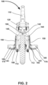
FIG. 2 illustrates rear view of the multipurpose vehicle ofFIG. 1 in side-loader mode; -
FIG. 3 illustrates a top plan view of the rear portion of the multipurpose vehicle ofFIG. 1 with the side board and wing board removed for simplicity; -
FIG. 4 illustrates a perspective view of a rear portion of a multipurpose vehicle in the compact mode wherein the wing boards are in vertical folded position, according to an embodiment of the present invention; -
FIG. 5 illustrates a perspective view of a rear portion of a multipurpose vehicle in the carry-on mode wherein the wing board is perpendicular to side board and swing arms are rotated by using a handle, according to an embodiment of the present invention; -
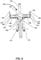
FIG. 6 illustrates rear view of the multipurpose vehicle ofFIG. 5 in carry-on mode; -
FIG. 7 illustrates a perspective view of a rear portion of the multipurpose vehicle in the flatbed mode wherein the wing board is parallel to side board, according to an embodiment of the present invention. -
FIG. 8 illustrates a perspective view of a lever arm and a hinge arm, wherein lever arm is pivotally connected to the hinge arm, according to an embodiment of the present invention; -
FIG. 9A - FIG. 9D illustrates various steps/procedures for connecting wing board and/or lever arm to the vehicle rack of the multipurpose vehicle ofFIG. 1 - FIG. 8 , according to an embodiment of the present invention; and -
FIG. 10 illustrates a side view of the multipurpose vehicle ofFIG. 1 in vertical parking mode wherein the multipurpose vehicle is resting on the ground surface. - Some embodiments, illustrating its features, will now be discussed in detail. The words "comprising," "having," "containing," and "including," and other forms thereof, are intended to be equivalent in meaning and be open ended in that an item or items following any one of these words is not meant to be an exhaustive listing of such item or items, or meant to be limited to only the listed item or items. It must also be noted that as used herein and in the appended claims, the singular forms "a," "an," and "the" include plural references unless the context clearly dictates otherwise. Although any methods, and systems similar or equivalent to those described herein can be used in the practice or testing of embodiments, the preferred methods, and systems are now described. The disclosed embodiments are merely exemplary.
- The various features and embodiments of a multipurpose vehicle of the present invention will now be described in conjunction with the accompanying figures, namely
FIGS. 1-10 . - Referring to accompanying figures, especially
FIG. 1 - FIG. 7 , amultipurpose vehicle 100 is shown capable of being used by a user for travelling across various places, in accordance with an embodiment of present invention. Themultipurpose vehicle 100 comprises a front portion and a rear portion (rear loader). The front portion of themultipurpose vehicle 100 comprises various parts such as but not limited to: wheels, frame, tubes, handles, seats, brakes and so on. The rear portion of themultipurpose vehicle 100 comprises avehicle frame 110 including avehicle rack 120 and a plurality ofconnector portions 130. The rear portion of themultipurpose vehicle 100 further comprises a plurality ofswing arms 140. Eachswing arm 140 comprises afirst end 142 and an oppositesecond end 144, wherein thefirst end 142 of twoswing arms 140 are rotatably connected to aconnector portion 130 of thevehicle frame 110. Theconnector portion 130 includes but not limited to: bolt axle, pivot pin and so on. As shown inFIG. 1 - FIG. 7 , thefirst end 142 of twoswing arms 140 is arranged at a common position. Thesecond end 144 of eachswing arm 140 is connected to alever arm 143. Themultipurpose vehicle 100 further comprises a plurality ofwing boards 150 wherein eachwing board 150 is connected to twolever arms 143. The connection between thewing board 150 and twolever arms 143 is achieved by any connection means including but not limited to: fasteners, welding, rivets, screws and so on. Eachlever arm 143 further comprises aconnector arrangement 145 for removably connecting thelever arm 143 to thevehicle rack 120. Themultipurpose vehicle 100 further comprises a plurality ofhinge arms 170 wherein eachhinge arm 170 is rotatably connected to thelever arm 143 by a pivoting means 160 which will be explained in greater detail in below description. Themultipurpose vehicle 100 further comprises a plurality ofside boards 180 wherein eachside board 180 is connected to two hingearms 170. The connection between theside board 180 and two hingearms 170 is achieved by any connection means including but not limited to: fasteners, welding, rivets, screws and so on. - A
handle 190 is connected tofirst end 142 of twoswing arms 140 wherein thehandle 190 is manually operable to enable adjustment of the rotation of at least twoswing arms 140. Thehandle 190 is further connected to aconnector portion 130 of thevehicle frame 110. The handle includes 190 but not limited to: a lever handle, a knob, a twist handle, a pull-push button, a manual switch and / or combination thereof. As shown inFIG. 1 - FIG. 7 , thehandle 190 is a lever type handle. - The
handle 190 has at least two positional settings. As shown inFIG. 1 , when thehandle 190 is operated in low positional setting (low mode), theswing arms 140 are positioned such that thewing board 150 is positioned below thevehicle rack 120 as further seen inFIG. 2 . As shown inFIG. 6 , when thehandle 190 is operated in high positional setting (high mode), theswing arms 140 are positioned such that thewing board 150 and thevehicle rack 120 are substantially at same height. The wing board(s) 150 and/or the side board(s) 180 of themultipurpose vehicle 100 are configured to be positioned relative to thevehicle frame 110 in multiple operating modes by operating at least one ofhandle 190 and/or connector arrangement(s) 145 which will be explained in greater detail in the below description. The multiple operating modes of themultipurpose vehicle 100 are selected by the user and the multiple operating modes could be one of following: side-loader mode (FIG. 1 ), compact mode (FIG. 4 ), carry-on mode (FIG. 5 ) and flat-bed mode (FIG. 7 ) which will be explained in greater detail in the below description. - As shown in
FIG. 1 - FIG. 7 , themultipurpose vehicle 100 comprises a pair ofwing boards 150 and a pair ofside boards 180. Awing board 150 and aside board 180 are positioned on one side (left side) of thevehicle frame 110. Further, awing board 150 and aside board 180 is positioned on other opposite side (right side) of thevehicle frame 110. - As shown in
FIG. 1 - FIG. 7 , thehandle 190 is connected to aconnector portion 130 of thevehicle frame 110. The other (remaining) connectingportion 130 is not connected to thehandle 190. - In an embodiment as shown in
FIG. 3 , a top plan view of the rear portion of themultipurpose vehicle 100 is shown with the side board and wing board removed from figure for simplicity. Thevehicle rack 120 comprises a plurality of T-bar slots 122 for removably connecting thelever arm 143 and/ or wing board 150 (FIG. 1 ) to thevehicle rack 120. Further, thevehicle rack 120 comprises a pair of stand-upwheels 124 for enabling vertical parking of the multipurpose vehicle. Further, thevehicle rack 120 comprises a plurality ofports 126 for removably connecting vehicle accessories (not shown) such as but not limited to seats.Ports 126 can receive fasteners such as but not limited to bolts, keys and so on. - In an embodiment as shown in
FIG. 1 andFIG. 3 , thevehicle frame 110 comprises a pair of stand-upfeet portion 112 for vertical parking of themultipurpose vehicle 110 which will be explained in greater detail with reference toFIG. 10 in the below description. - As shown in
FIG. 1 , themultipurpose vehicle 100 is positioned in the side-loader mode. In the side-loader mode, theside board 180 and thewing board 150 are positioned substantially at an angle of 90 degrees apart i.e. perpendicular to each other. The side-loader mode is useful for carrying people on the back of themultipurpose vehicle 100 such that a person can place his/her foot on the sideboard(s) 180 of themultipurpose vehicle 100. However, other uses of side-loader mode is also possible and within the scope of the present invention. - In an embodiment as shown in
FIG. 1 , theside board 180 comprises a plurality ofelongate slots 182. Further, thewing board 150 comprises a plurality ofelongate projections 152. Theelongate slots 182 mates withelongate projections 152 for proper mating of theside board 180 and thewing board 150 when themultipurpose vehicle 100 is positioned in compact mode (FIG. 4 ). - In another embodiment (not shown in figures), the
side board 180 comprises a plurality of cushion pads (not shown) for anti-rattle effect and/or better grip. - In another embodiment (not shown in figures), the
swing arm 140 is integrally connected (formed) to alever arm 143 to form a one - piece structure. - In another embodiment (not shown in figures), two
lever arms 143 are integrally connected (formed) to awing board 150 to form a one - piece structure. - In another embodiment (not shown in figures), the swing arm(s) 140, the lever arm(s) 143 and the
wing board 150 are all integrally connected (formed) to form a one - piece structure. - In another embodiment (not shown in figures), two hinge
arms 170 are integrally connected (formed) to aside board 180 to form a one - piece structure. - In another embodiment (not shown in figures), the
multipurpose vehicle 100 comprises more than twowing boards 150 and more than twoside boards 180. At least twowing board 150 and at least twoside boards 180 is positioned on one side (left side) of thevehicle frame 110. Further, at least twowing boards 150 and at least twoside boards 180 is positioned on other opposite side (right side) of thevehicle frame 110. - In operation, when it is desired to position the
multipurpose vehicle 100 in the compact mode as shown inFIG. 4 , thehinge arm 170 is rotated relative to thelever arm 143 by using a pivoting means 160 which will be explained in greater detail in the below description. Eachwing board 150 is connected to twolever arms 143 and eachside board 180 is connected to two hingearms 170. Therefore, theside board 180 rotates relative to thewing board 150 such that theside board 180 is substantially parallel relative to thewing board 150 in the compact mode. The compact mode occupies minimum space and is useful when no luggage carrying function / rear passenger carrying function is needed. - In operation, when it is desired to position the
multipurpose vehicle 100 in the carry-on mode as shown inFIG. 5 andFIG. 6 , theswing arms 140 are rotated by using ahandle 190. A user operates thehandle 190 manually in high positional setting (high mode), then theswing arms 140 are rotated by the user at an angle of 90 degrees in anti-clockwise direction when seen from the rear view of multipurpose vehicle 100 (FIG. 2 andFIG. 6 ). Thesecond end 144 of eachswing arm 140 is connected to alever arm 143. Eachwing board 150 is connected to twolever arms 143 and eachside board 180 is connected to two hingearms 170. Eachlever arm 143 further comprises aconnector arrangement 145 for removably connecting thelever arm 143 to thevehicle rack 120. After theswing arms 140 are rotated by using ahandle 190, thelever arm 143 also rotates in the same direction. Afterwards, thelever arm 143 is connected to thevehicle rack 120 by using aconnector arrangement 145 which will be described in greater detail in the below description. As seen inFIG. 5 , theside board 180 is rotated relative to thewing board 150 using pivoting means 160 such that theside board 180 is substantially perpendicular (90 degrees) relative to thewing board 150 in the carry-on mode. The carry-on mode is useful for carrying luggage on the back of themultipurpose vehicle 100 that needs side retention. However, other uses of carry-on mode are also possible and are within the scope of the present invention. - In operation, when it is desired to position the
multipurpose vehicle 100 in the flatbed mode as shown inFIG. 7 , thehinge arm 170 is rotated relative to thelever arm 143 by using a pivoting means 160. Eachwing board 150 is connected to twolever arms 143 and eachside board 180 is connected to two hingearms 170. Theside board 180 is rotated relative to thewing board 150 such that theside board 180 is substantially parallel relative to thewing board 150 in the flatbed mode. The flatbed mode is useful for carrying luggage on the back of themultipurpose vehicle 100 that has a wide surface area (dimensions) and may also slightly overhang outside theside board 180 and / or thewing board 150. Further, a rope / harness (not shown) could be used for tying the luggage securely placed on theside board 180 and / or thewing board 150. However, other uses of flatbed mode are also possible and is within the scope of the present invention. - It should be obvious to the one skilled in the art that various modes of the
multipurpose vehicle 100 selected from the: side-loader mode, compact mode, carry-on mode and flat-bed mode can be achieved by simply reversing the above steps with little or no variation. -
FIG. 8 illustrates ahinge arm 170 rotatably connected to alever arm 143 by using a pivoting means 160. The pivoting means 160 comprises anaxle bolt 162 that allows rotation of thehinge arm 170 relative to thelever arm 143 in the predefined angular range of rotational movement. Further, the pivoting means 160 comprises an O ring (not shown) to provide frictional force that acts in opposite direction to the force applied on thehinge arm 170 by the user. Further, the pivoting means 160 comprises an angle stop face (not shown) to limit the angular range of rotational movement of thehinge arm 170 relative to thelever arm 143. In an embodiment, the predefined angular range of rotational movement of thehinge arm 170 relative to thelever arm 143 is 0 degrees to 90 degrees. Further, it should be obvious to the one skilled in the art that thehinge arm 170 could be rotatably positioned in between 0 to 90 degrees relative to thelever arm 143. For instance, thehinge arm 170 could be rotatably positioned at angle of 30 degrees relative to thelever arm 143. - In another embodiment, the predefined angular range of rotational movement of the
hinge arm 170 relative to thelever arm 143 is 0 degree to 180 degrees. - Further, the
lever arm 143 comprises aconnector arrangement 145 that removably connects thelever arm 143 to thevehicle rack 120. Theconnector arrangement 145 comprises alever 146, T-bar 147, arubber bumper 148, apivot bolt 149A and apivot pin 149B. Thelever 146 is disposed in a slot 151 (FIG. 9B ) of thewing board 150 and thelever 146 is rotatably connected to the T-bar 147 by using thepivot bolt 149A. Further, thelever 146 is rotatably connected to thelever arm 143 by using thepivot pin 149B. The steps / procedure for connecting thelever arm 143 and / orwing board 150 to thevehicle rack 120 will be described in greater detail in the below description (FIG. 9A - FIG. 9D ). -
FIG. 9A - FIG. 9D illustrate a method / procedure of connecting thelever arm 143 and / orwing board 150 to thevehicle rack 120. As shown inFIG. 9A , the T-bar 147 comprises anelongate part 147A and asmall part 147B. Theelongate part 147A and asmall part 147B are integrally formed and are perpendicular relative to one other, thereby achieving T shape of T-bar 147. InFIG. 9A , theelongate part 147A of the T-bar 147 is movably disposed in therubber bumper 148 and thelever 146 is disposed in theslot 151 of thewing board 150 and themultipurpose vehicle 100 is operated in the side-loader mode (FIG. 1 ) or the compact mode (FIG. 4 ). Further, InFIG. 9A , the handle 190 (FIG. 1 - FIG. 7 ) is operated in low positional setting (low mode). When the handle 190 (FIG. 1 - FIG. 7 ) is operated in high positional setting (high mode), then the user lifts the T-bar 147 by rotating thelever 146 usingpivot pin 149B and / orpivot bolt 149A as seen inFIG. 9B such that theelongate part 147A of the T-bar 147 moves out from therubber bumper 148 and thelever 146 comes out from theslot 151 of thewing board 150. Afterwards, thesmall part 147B of the T-bar 147 is inserted in the T-bar slot 122 as shown inFIG. 9C . Afterwards, thelever 146 is rotated such that thelever 146 moves in theslot 151 of thewing board 150 and theelongate part 147A of the T-bar 147 moves in therubber bumper 148 as shown inFIG. 9D . Afterwards, the user can select the flat-bed mode (FIG. 7 ) or carry-on mode (FIG. 5 ) depending on his / her requirements. - By merely reversing the above steps with little or no variation, the
lever arm 143 and / orwing board 150 can be disconnected from thevehicle rack 120 with simplicity. -
FIG. 10 illustrates a vertical parking mode of themultipurpose vehicle 100. The pair of stand-upwheels 124 of thevehicle rack 120 and the stand-upfeet portion 112 of thevehicle frame 110 enables vertical parking of themultipurpose vehicle 110 on aground surface 200. As shown inFIG. 10 , themultipurpose vehicle 110 is vertically parked on theground surface 200 in the side-loader mode. However, it is obvious to the one skilled in the art that themultipurpose vehicle 110 could be vertically parked on theground surface 200 in other modes also wherein other modes include carry-on mode, compact mode and flatbed mode. While the arrangement illustrated inFIG. 10 is effective in accordance with the present invention, themultipurpose vehicle 100 is uniquely designed so that it can be vertically parked on aground surface 200. - In another embodiment (not shown in figures), the
multipurpose vehicle 100 comprises asingle wingboard 150 and asingle side board 180. Thesingle wingboard 150 and asingle side board 180 are disposed on only one side (i.e. left side or right side) of theframe 110. - The
multipurpose vehicle 100 according to various embodiments (FIG. 1 to FIG. 10 ) of the present invention comprises fourswing arms 140, fourlever arms 143, four hingearms 170, twoconnector portions 130, twoside boards 180, fourconnection arrangements 145 , twowing boards 150 and onehandle 190. The left side and the opposite right side of thevehicle frame 110 are identical and comprise similar parts / components. Further, the number of the parts and / or components of themultipurpose vehicle 100 can vary and will depend on user requirements. - The
multipurpose cycle vehicle 100 according to various embodiments of the present invention comprises a bicycle. However, the scope of the invention covers other types of multipurpose cycle vehicles such as: a tricycle, a motor cycle, an electric vehicle, a scooter, a moped or an electric bike. - The scope of the invention is defined by the appended claims.
Claims (15)
- - A human-propelled and/or motorized multipurpose cycle vehicle (100) comprising :a vehicle frame (110) comprising a vehicle rack (120), and a plurality of connector portions (130) ;a plurality of swing arms (140), wherein each swing arm (140) comprises a first end (142) and an opposite second end (144), wherein the first end (142) of each swing arm (140) is rotatably connected to one of said connector portions (130) of the vehicle frame (110) ;characterized in that the multipurpose cycle vehicle (100) further comprises :a plurality of lever arms (143), wherein each lever arm (143) is connected to the second end (144) of one of said swing arms (140), wherein each lever arm (143) comprises a connector arrangement (145) for removably connecting the lever arm (143) to the vehicle rack (120) ;at least one wing board (150), wherein the at least one wing board (150) is connected to two of said lever arms (143) ;a plurality of hinge arms (170), wherein each hinge arm (170) is rotatably connected to one of said lever arms (143) by a pivoting means (160) ;at least one side board (180), wherein the at least one side board (180) is connected to two of said hinge arms (170) ;a handle (190) connected to one of said connector portions (130) of the vehicle frame (110) ;wherein the handle (190) is manually operable to enable adjustment of the rotation of at least two of said swing arms (140) ; andwherein the at least one wing board (150) and/or the at least one side board (180) of the multipurpose cycle vehicle (100) are configured to be positioned relative to the vehicle frame in multiple operating modes by operating at least one of the handle (190) and/or connector arrangements (145).
- - A multipurpose cycle vehicle (100) as claimed in claim 1, wherein the multipurpose cycle vehicle (100) comprises a bicycle, a tricycle, a motor cycle, an electric vehicle, a scooter, a moped or an electric bike.
- - A multipurpose cycle vehicle (100) as claimed in claim 1, wherein the vehicle frame (110) comprises a pair of stand-up feet portion (112).
- - A multipurpose cycle vehicle (100) as claimed in claim 1, wherein the vehicle rack (120) comprises a plurality of T-bar slots (122), and/or a pair of stand-up wheels (124), and/or a plurality of ports (126) for removably connecting multipurpose cycle vehicle accessories.
- - A multipurpose cycle vehicle (100) as claimed in claim 1, wherein the number of connector portions (130) is two, and the number of swing arms (140) is two or four.
- - A multipurpose cycle vehicle (100) as claimed in claim 1, wherein the swing arms (140) are rotatable relative to their respective connector portion (130) of the vehicle frame (110) by an angle of 90 degrees.
- - A multipurpose cycle vehicle (100) as claimed in claim 1, wherein each connector portion (130) comprises a bolt axle.
- - A multipurpose cycle vehicle (100) as claimed in claim 1, wherein each connector arrangement (145) comprises a lever (146), a T-bar (147), a rubber bumper (148), a pivot bolt (149A) and a pivot pin (149B).
- - A multipurpose cycle vehicle (100) as claimed in claim 1, wherein said at least one wing board (150) comprises a plurality of elongate projections (152).
- - A multipurpose cycle vehicle (100) as claimed in claim 1, wherein each pivoting means (160) comprises an axle bolt (162).
- - A multipurpose cycle vehicle (100) as claimed in claim 1, wherein said at least one side board (180) comprises a plurality of elongate slots (182).
- - A multipurpose cycle vehicle (100) as claimed in claim 1, wherein said at least one side board (180) comprises a plurality of cushion pads.
- - A multipurpose cycle vehicle (100) as claimed in claim 1, wherein said at least one side board (180) is rotatable relative to its respective wing board (150) by an angle of 90 degrees.
- - A multipurpose cycle vehicle (100) as claimed in claim 1, wherein the handle (190) comprises a lever handle, a knob, a twist handle, a pull-push button or a manual switch.
- - A multipurpose cycle vehicle (100) as claimed in claim 1, wherein the multiple operating modes of the multipurpose cycle vehicle (100) are : compact mode, side-loader mode, carry-on mode and flat-bed mode.
Applications Claiming Priority (1)
| Application Number | Priority Date | Filing Date | Title |
|---|---|---|---|
| US202063053133P | 2020-07-17 | 2020-07-17 |
Publications (2)
| Publication Number | Publication Date |
|---|---|
| EP3939870A1 EP3939870A1 (en) | 2022-01-19 |
| EP3939870B1 true EP3939870B1 (en) | 2023-08-09 |
Family
ID=77167945
Family Applications (1)
| Application Number | Title | Priority Date | Filing Date |
|---|---|---|---|
| EP21020369.1A Active EP3939870B1 (en) | 2020-07-17 | 2021-07-16 | Multipurpose vehicle |
Country Status (2)
| Country | Link |
|---|---|
| US (1) | US11801909B2 (en) |
| EP (1) | EP3939870B1 (en) |
Families Citing this family (4)
| Publication number | Priority date | Publication date | Assignee | Title |
|---|---|---|---|---|
| US11299226B2 (en) * | 2020-08-07 | 2022-04-12 | MOBILITY HOLDINGS, Ltd. | Bicycle |
| USD1035502S1 (en) * | 2023-03-16 | 2024-07-16 | Yadea Technology Group Co., Ltd | Electric bicycle |
| USD1060138S1 (en) * | 2023-03-29 | 2025-02-04 | Honbon New Energy Co., Ltd | Electric bicycle |
| US20250145239A1 (en) * | 2023-11-02 | 2025-05-08 | MOBILITY HOLDINGS, Ltd. | Multi-angle Adjustable Bicycle Side Deck |
Family Cites Families (16)
| Publication number | Priority date | Publication date | Assignee | Title |
|---|---|---|---|---|
| US605188A (en) * | 1898-06-07 | Bundle-carrier for bicycles | ||
| GB653768A (en) * | 1948-12-06 | 1951-05-23 | Max Schneider | Luggage carrier attached to the back-wheel stays of push bicycles and motor bicycles |
| US3873127A (en) | 1973-10-01 | 1975-03-25 | Kain S Research And Dev Compan | Multi-purpose bicycle rack |
| US3934770A (en) * | 1974-08-30 | 1976-01-27 | Elizabeth Larsen | Collapsible bicycle article carrier |
| US4662548A (en) * | 1977-02-14 | 1987-05-05 | Eclipse, Inc. | Pannier and mounting arrangement for cycles |
| CN2202082Y (en) * | 1994-07-07 | 1995-06-28 | 张成东 | Bicycle carrier |
| US5687894A (en) * | 1995-07-07 | 1997-11-18 | Cavallaro; Cynthia A. | Bicycle rack |
| TW429920U (en) * | 2000-02-18 | 2001-04-11 | Pacific Cycles Inc | Bicycle upright parking structure |
| DE10104958A1 (en) * | 2001-02-03 | 2002-08-22 | Albert Frick | Extra luggage rack for bicycle has bottom which can be turned on one or more hinges out to about 90 degrees from rear wall and also folded up parallel to rear wall |
| US8074852B2 (en) * | 2009-03-05 | 2011-12-13 | Wald Llc | Detachable collapsible bicycle basket |
| KR200445719Y1 (en) * | 2009-04-01 | 2009-08-28 | 김보라 | Bicycle with extended rack |
| US10689050B2 (en) * | 2017-05-23 | 2020-06-23 | Shawn Getchell | Rear mounted bicycle rack system |
| CN107458508A (en) * | 2017-08-16 | 2017-12-12 | 合肥向宇互联网科技有限公司 | Rear-mounted bicycle basket and its bicycle |
| CN208248361U (en) * | 2018-03-20 | 2018-12-18 | 天津广恩科技有限公司 | A kind of dual-purpose bicycle back seat |
| DE202020002174U1 (en) * | 2020-05-16 | 2020-06-17 | Justus Börger | Multifunctional extension of a bike rack for additional transport options |
| US11299226B2 (en) * | 2020-08-07 | 2022-04-12 | MOBILITY HOLDINGS, Ltd. | Bicycle |
-
2021
- 2021-07-15 US US17/376,362 patent/US11801909B2/en active Active
- 2021-07-16 EP EP21020369.1A patent/EP3939870B1/en active Active
Also Published As
| Publication number | Publication date |
|---|---|
| US11801909B2 (en) | 2023-10-31 |
| US20210339813A1 (en) | 2021-11-04 |
| EP3939870A1 (en) | 2022-01-19 |
Similar Documents
| Publication | Publication Date | Title |
|---|---|---|
| US11801909B2 (en) | Multipurpose vehicle | |
| US8387734B2 (en) | Low speed vehicle | |
| EP0058526B1 (en) | Foldable and portable bicycle convertible into a shopping cart | |
| US7543836B2 (en) | Flip-down footrest for an all-terrain vehicle | |
| CA2603955A1 (en) | Dual-posture electric assist bicycle | |
| US20180099722A1 (en) | Foldable Electric Vehicle | |
| US10858057B2 (en) | Hoverboard buddy system | |
| US20040094925A1 (en) | Cambering vehicle | |
| US20060220334A1 (en) | Article carrying cart | |
| US7232143B1 (en) | Folding bicycle assembly | |
| US20030201621A1 (en) | Vehicle having auxiliary controlling device | |
| CN108463402A (en) | Two-wheeled vehicle | |
| JP2001178788A (en) | Walking assistance vehicle | |
| CN215475529U (en) | Vehicle system | |
| CA2628447A1 (en) | Wheeled dolly that unfolds into a personal vehicle | |
| JP4225067B2 (en) | Loading device for small electric vehicle | |
| JP5062515B2 (en) | Folding bike | |
| US6406046B1 (en) | Bicycle passenger carrier | |
| WO2002085695A1 (en) | Trolley for luggage or other loads | |
| CA2655495A1 (en) | Dual-posture electric assist bicycle with improved ergonomic functionality | |
| KR20190069807A (en) | Motorized Kick Board | |
| US20240367745A1 (en) | Trike-shopping cart transformer | |
| CN217533112U (en) | Portable foldable electric walking aid vehicle | |
| CN211308862U (en) | Folding bicycle | |
| KR200373872Y1 (en) | bicycles |
Legal Events
| Date | Code | Title | Description |
|---|---|---|---|
| PUAI | Public reference made under article 153(3) epc to a published international application that has entered the european phase |
Free format text: ORIGINAL CODE: 0009012 |
|
| STAA | Information on the status of an ep patent application or granted ep patent |
Free format text: STATUS: THE APPLICATION HAS BEEN PUBLISHED |
|
| AK | Designated contracting states |
Kind code of ref document: A1 Designated state(s): AL AT BE BG CH CY CZ DE DK EE ES FI FR GB GR HR HU IE IS IT LI LT LU LV MC MK MT NL NO PL PT RO RS SE SI SK SM TR |
|
| RAP3 | Party data changed (applicant data changed or rights of an application transferred) |
Owner name: YUBA INTERNATIONAL INC. |
|
| STAA | Information on the status of an ep patent application or granted ep patent |
Free format text: STATUS: REQUEST FOR EXAMINATION WAS MADE |
|
| 17P | Request for examination filed |
Effective date: 20220718 |
|
| RBV | Designated contracting states (corrected) |
Designated state(s): AL AT BE BG CH CY CZ DE DK EE ES FI FR GB GR HR HU IE IS IT LI LT LU LV MC MK MT NL NO PL PT RO RS SE SI SK SM TR |
|
| RIC1 | Information provided on ipc code assigned before grant |
Ipc: B62K 19/06 20060101ALN20230307BHEP Ipc: B62J 25/04 20200101ALI20230307BHEP Ipc: B62J 1/14 20060101ALI20230307BHEP Ipc: B62H 1/00 20060101ALI20230307BHEP Ipc: B62K 7/04 20060101ALI20230307BHEP Ipc: B62K 19/46 20060101ALI20230307BHEP Ipc: B62J 7/04 20060101AFI20230307BHEP |
|
| GRAP | Despatch of communication of intention to grant a patent |
Free format text: ORIGINAL CODE: EPIDOSNIGR1 |
|
| STAA | Information on the status of an ep patent application or granted ep patent |
Free format text: STATUS: GRANT OF PATENT IS INTENDED |
|
| RIC1 | Information provided on ipc code assigned before grant |
Ipc: B62K 19/06 20060101ALN20230314BHEP Ipc: B62J 25/04 20200101ALI20230314BHEP Ipc: B62J 1/14 20060101ALI20230314BHEP Ipc: B62H 1/00 20060101ALI20230314BHEP Ipc: B62K 7/04 20060101ALI20230314BHEP Ipc: B62K 19/46 20060101ALI20230314BHEP Ipc: B62J 7/04 20060101AFI20230314BHEP |
|
| INTG | Intention to grant announced |
Effective date: 20230414 |
|
| RIN1 | Information on inventor provided before grant (corrected) |
Inventor name: SARRAZIN, BENJAMIN Inventor name: DE LA FUENTE, TIMOTHY Inventor name: LEDINGHAM, DUNCAN |
|
| P01 | Opt-out of the competence of the unified patent court (upc) registered |
Effective date: 20230516 |
|
| GRAS | Grant fee paid |
Free format text: ORIGINAL CODE: EPIDOSNIGR3 |
|
| GRAA | (expected) grant |
Free format text: ORIGINAL CODE: 0009210 |
|
| STAA | Information on the status of an ep patent application or granted ep patent |
Free format text: STATUS: THE PATENT HAS BEEN GRANTED |
|
| AK | Designated contracting states |
Kind code of ref document: B1 Designated state(s): AL AT BE BG CH CY CZ DE DK EE ES FI FR GB GR HR HU IE IS IT LI LT LU LV MC MK MT NL NO PL PT RO RS SE SI SK SM TR |
|
| REG | Reference to a national code |
Ref country code: GB Ref legal event code: FG4D |
|
| REG | Reference to a national code |
Ref country code: CH Ref legal event code: EP |
|
| REG | Reference to a national code |
Ref country code: IE Ref legal event code: FG4D |
|
| REG | Reference to a national code |
Ref country code: DE Ref legal event code: R096 Ref document number: 602021004024 Country of ref document: DE |
|
| REG | Reference to a national code |
Ref country code: LT Ref legal event code: MG9D |
|
| REG | Reference to a national code |
Ref country code: NL Ref legal event code: MP Effective date: 20230809 |
|
| REG | Reference to a national code |
Ref country code: AT Ref legal event code: MK05 Ref document number: 1597232 Country of ref document: AT Kind code of ref document: T Effective date: 20230809 |
|
| PG25 | Lapsed in a contracting state [announced via postgrant information from national office to epo] |
Ref country code: GR Free format text: LAPSE BECAUSE OF FAILURE TO SUBMIT A TRANSLATION OF THE DESCRIPTION OR TO PAY THE FEE WITHIN THE PRESCRIBED TIME-LIMIT Effective date: 20231110 |
|
| PG25 | Lapsed in a contracting state [announced via postgrant information from national office to epo] |
Ref country code: IS Free format text: LAPSE BECAUSE OF FAILURE TO SUBMIT A TRANSLATION OF THE DESCRIPTION OR TO PAY THE FEE WITHIN THE PRESCRIBED TIME-LIMIT Effective date: 20231209 |
|
| PG25 | Lapsed in a contracting state [announced via postgrant information from national office to epo] |
Ref country code: SE Free format text: LAPSE BECAUSE OF FAILURE TO SUBMIT A TRANSLATION OF THE DESCRIPTION OR TO PAY THE FEE WITHIN THE PRESCRIBED TIME-LIMIT Effective date: 20230809 Ref country code: RS Free format text: LAPSE BECAUSE OF FAILURE TO SUBMIT A TRANSLATION OF THE DESCRIPTION OR TO PAY THE FEE WITHIN THE PRESCRIBED TIME-LIMIT Effective date: 20230809 Ref country code: PT Free format text: LAPSE BECAUSE OF FAILURE TO SUBMIT A TRANSLATION OF THE DESCRIPTION OR TO PAY THE FEE WITHIN THE PRESCRIBED TIME-LIMIT Effective date: 20231211 Ref country code: NO Free format text: LAPSE BECAUSE OF FAILURE TO SUBMIT A TRANSLATION OF THE DESCRIPTION OR TO PAY THE FEE WITHIN THE PRESCRIBED TIME-LIMIT Effective date: 20231109 Ref country code: NL Free format text: LAPSE BECAUSE OF FAILURE TO SUBMIT A TRANSLATION OF THE DESCRIPTION OR TO PAY THE FEE WITHIN THE PRESCRIBED TIME-LIMIT Effective date: 20230809 Ref country code: LV Free format text: LAPSE BECAUSE OF FAILURE TO SUBMIT A TRANSLATION OF THE DESCRIPTION OR TO PAY THE FEE WITHIN THE PRESCRIBED TIME-LIMIT Effective date: 20230809 Ref country code: LT Free format text: LAPSE BECAUSE OF FAILURE TO SUBMIT A TRANSLATION OF THE DESCRIPTION OR TO PAY THE FEE WITHIN THE PRESCRIBED TIME-LIMIT Effective date: 20230809 Ref country code: IS Free format text: LAPSE BECAUSE OF FAILURE TO SUBMIT A TRANSLATION OF THE DESCRIPTION OR TO PAY THE FEE WITHIN THE PRESCRIBED TIME-LIMIT Effective date: 20231209 Ref country code: HR Free format text: LAPSE BECAUSE OF FAILURE TO SUBMIT A TRANSLATION OF THE DESCRIPTION OR TO PAY THE FEE WITHIN THE PRESCRIBED TIME-LIMIT Effective date: 20230809 Ref country code: GR Free format text: LAPSE BECAUSE OF FAILURE TO SUBMIT A TRANSLATION OF THE DESCRIPTION OR TO PAY THE FEE WITHIN THE PRESCRIBED TIME-LIMIT Effective date: 20231110 Ref country code: FI Free format text: LAPSE BECAUSE OF FAILURE TO SUBMIT A TRANSLATION OF THE DESCRIPTION OR TO PAY THE FEE WITHIN THE PRESCRIBED TIME-LIMIT Effective date: 20230809 Ref country code: AT Free format text: LAPSE BECAUSE OF FAILURE TO SUBMIT A TRANSLATION OF THE DESCRIPTION OR TO PAY THE FEE WITHIN THE PRESCRIBED TIME-LIMIT Effective date: 20230809 |
|
| PG25 | Lapsed in a contracting state [announced via postgrant information from national office to epo] |
Ref country code: PL Free format text: LAPSE BECAUSE OF FAILURE TO SUBMIT A TRANSLATION OF THE DESCRIPTION OR TO PAY THE FEE WITHIN THE PRESCRIBED TIME-LIMIT Effective date: 20230809 |
|
| PG25 | Lapsed in a contracting state [announced via postgrant information from national office to epo] |
Ref country code: ES Free format text: LAPSE BECAUSE OF FAILURE TO SUBMIT A TRANSLATION OF THE DESCRIPTION OR TO PAY THE FEE WITHIN THE PRESCRIBED TIME-LIMIT Effective date: 20230809 |
|
| PG25 | Lapsed in a contracting state [announced via postgrant information from national office to epo] |
Ref country code: SM Free format text: LAPSE BECAUSE OF FAILURE TO SUBMIT A TRANSLATION OF THE DESCRIPTION OR TO PAY THE FEE WITHIN THE PRESCRIBED TIME-LIMIT Effective date: 20230809 Ref country code: RO Free format text: LAPSE BECAUSE OF FAILURE TO SUBMIT A TRANSLATION OF THE DESCRIPTION OR TO PAY THE FEE WITHIN THE PRESCRIBED TIME-LIMIT Effective date: 20230809 Ref country code: ES Free format text: LAPSE BECAUSE OF FAILURE TO SUBMIT A TRANSLATION OF THE DESCRIPTION OR TO PAY THE FEE WITHIN THE PRESCRIBED TIME-LIMIT Effective date: 20230809 Ref country code: EE Free format text: LAPSE BECAUSE OF FAILURE TO SUBMIT A TRANSLATION OF THE DESCRIPTION OR TO PAY THE FEE WITHIN THE PRESCRIBED TIME-LIMIT Effective date: 20230809 Ref country code: DK Free format text: LAPSE BECAUSE OF FAILURE TO SUBMIT A TRANSLATION OF THE DESCRIPTION OR TO PAY THE FEE WITHIN THE PRESCRIBED TIME-LIMIT Effective date: 20230809 Ref country code: CZ Free format text: LAPSE BECAUSE OF FAILURE TO SUBMIT A TRANSLATION OF THE DESCRIPTION OR TO PAY THE FEE WITHIN THE PRESCRIBED TIME-LIMIT Effective date: 20230809 Ref country code: SK Free format text: LAPSE BECAUSE OF FAILURE TO SUBMIT A TRANSLATION OF THE DESCRIPTION OR TO PAY THE FEE WITHIN THE PRESCRIBED TIME-LIMIT Effective date: 20230809 |
|
| REG | Reference to a national code |
Ref country code: DE Ref legal event code: R097 Ref document number: 602021004024 Country of ref document: DE |
|
| PG25 | Lapsed in a contracting state [announced via postgrant information from national office to epo] |
Ref country code: IT Free format text: LAPSE BECAUSE OF FAILURE TO SUBMIT A TRANSLATION OF THE DESCRIPTION OR TO PAY THE FEE WITHIN THE PRESCRIBED TIME-LIMIT Effective date: 20230809 |
|
| PLBE | No opposition filed within time limit |
Free format text: ORIGINAL CODE: 0009261 |
|
| STAA | Information on the status of an ep patent application or granted ep patent |
Free format text: STATUS: NO OPPOSITION FILED WITHIN TIME LIMIT |
|
| 26N | No opposition filed |
Effective date: 20240513 |
|
| PG25 | Lapsed in a contracting state [announced via postgrant information from national office to epo] |
Ref country code: SI Free format text: LAPSE BECAUSE OF FAILURE TO SUBMIT A TRANSLATION OF THE DESCRIPTION OR TO PAY THE FEE WITHIN THE PRESCRIBED TIME-LIMIT Effective date: 20230809 |
|
| PGFP | Annual fee paid to national office [announced via postgrant information from national office to epo] |
Ref country code: FR Payment date: 20240606 Year of fee payment: 4 |
|
| PGFP | Annual fee paid to national office [announced via postgrant information from national office to epo] |
Ref country code: DE Payment date: 20240712 Year of fee payment: 4 |
|
| PGFP | Annual fee paid to national office [announced via postgrant information from national office to epo] |
Ref country code: BE Payment date: 20240726 Year of fee payment: 4 |
|
| PGFP | Annual fee paid to national office [announced via postgrant information from national office to epo] |
Ref country code: CH Payment date: 20240805 Year of fee payment: 4 |
|
| PG25 | Lapsed in a contracting state [announced via postgrant information from national office to epo] |
Ref country code: BG Free format text: LAPSE BECAUSE OF FAILURE TO SUBMIT A TRANSLATION OF THE DESCRIPTION OR TO PAY THE FEE WITHIN THE PRESCRIBED TIME-LIMIT Effective date: 20230809 |
|
| PG25 | Lapsed in a contracting state [announced via postgrant information from national office to epo] |
Ref country code: BG Free format text: LAPSE BECAUSE OF FAILURE TO SUBMIT A TRANSLATION OF THE DESCRIPTION OR TO PAY THE FEE WITHIN THE PRESCRIBED TIME-LIMIT Effective date: 20230809 |
|
| PG25 | Lapsed in a contracting state [announced via postgrant information from national office to epo] |
Ref country code: MC Free format text: LAPSE BECAUSE OF FAILURE TO SUBMIT A TRANSLATION OF THE DESCRIPTION OR TO PAY THE FEE WITHIN THE PRESCRIBED TIME-LIMIT Effective date: 20230809 |
|
| PG25 | Lapsed in a contracting state [announced via postgrant information from national office to epo] |
Ref country code: LU Free format text: LAPSE BECAUSE OF NON-PAYMENT OF DUE FEES Effective date: 20240716 |
|
| PG25 | Lapsed in a contracting state [announced via postgrant information from national office to epo] |
Ref country code: LU Free format text: LAPSE BECAUSE OF NON-PAYMENT OF DUE FEES Effective date: 20240716 |
|
| PG25 | Lapsed in a contracting state [announced via postgrant information from national office to epo] |
Ref country code: IE Free format text: LAPSE BECAUSE OF NON-PAYMENT OF DUE FEES Effective date: 20240716 |
|
| PG25 | Lapsed in a contracting state [announced via postgrant information from national office to epo] |
Ref country code: CY Free format text: LAPSE BECAUSE OF FAILURE TO SUBMIT A TRANSLATION OF THE DESCRIPTION OR TO PAY THE FEE WITHIN THE PRESCRIBED TIME-LIMIT; INVALID AB INITIO Effective date: 20210716 |
|
| REG | Reference to a national code |
Ref country code: DE Ref legal event code: R119 Ref document number: 602021004024 Country of ref document: DE |
|
| REG | Reference to a national code |
Ref country code: CH Ref legal event code: H13 Free format text: ST27 STATUS EVENT CODE: U-0-0-H10-H13 (AS PROVIDED BY THE NATIONAL OFFICE) Effective date: 20260224 |
|
| PG25 | Lapsed in a contracting state [announced via postgrant information from national office to epo] |
Ref country code: HU Free format text: LAPSE BECAUSE OF FAILURE TO SUBMIT A TRANSLATION OF THE DESCRIPTION OR TO PAY THE FEE WITHIN THE PRESCRIBED TIME-LIMIT; INVALID AB INITIO Effective date: 20210716 |
|
| GBPC | Gb: european patent ceased through non-payment of renewal fee |
Effective date: 20250716 |
|
| REG | Reference to a national code |
Ref country code: BE Ref legal event code: MM Effective date: 20250731 |
|
| PG25 | Lapsed in a contracting state [announced via postgrant information from national office to epo] |
Ref country code: GB Free format text: LAPSE BECAUSE OF NON-PAYMENT OF DUE FEES Effective date: 20250716 |
|
| PG25 | Lapsed in a contracting state [announced via postgrant information from national office to epo] |
Ref country code: DE Free format text: LAPSE BECAUSE OF NON-PAYMENT OF DUE FEES Effective date: 20260203 |
|
| PG25 | Lapsed in a contracting state [announced via postgrant information from national office to epo] |
Ref country code: BE Free format text: LAPSE BECAUSE OF NON-PAYMENT OF DUE FEES Effective date: 20250731 |
|
| PG25 | Lapsed in a contracting state [announced via postgrant information from national office to epo] |
Ref country code: FR Free format text: LAPSE BECAUSE OF NON-PAYMENT OF DUE FEES Effective date: 20250731 |
|
| PG25 | Lapsed in a contracting state [announced via postgrant information from national office to epo] |
Ref country code: CH Free format text: LAPSE BECAUSE OF NON-PAYMENT OF DUE FEES Effective date: 20250731 |