EP3939827B1 - Backrest for a vehicle - Google Patents
Backrest for a vehicle Download PDFInfo
- Publication number
- EP3939827B1 EP3939827B1 EP21196153.7A EP21196153A EP3939827B1 EP 3939827 B1 EP3939827 B1 EP 3939827B1 EP 21196153 A EP21196153 A EP 21196153A EP 3939827 B1 EP3939827 B1 EP 3939827B1
- Authority
- EP
- European Patent Office
- Prior art keywords
- backrest
- fastening
- support element
- backrest according
- fastening element
- Prior art date
- Legal status (The legal status is an assumption and is not a legal conclusion. Google has not performed a legal analysis and makes no representation as to the accuracy of the status listed.)
- Active
Links
Images



Classifications
-
- B—PERFORMING OPERATIONS; TRANSPORTING
- B60—VEHICLES IN GENERAL
- B60N—SEATS SPECIALLY ADAPTED FOR VEHICLES; VEHICLE PASSENGER ACCOMMODATION NOT OTHERWISE PROVIDED FOR
- B60N2/00—Seats specially adapted for vehicles; Arrangement or mounting of seats in vehicles
- B60N2/24—Seats specially adapted for vehicles; Arrangement or mounting of seats in vehicles for particular purposes or particular vehicles
- B60N2/242—Bus seats
-
- B—PERFORMING OPERATIONS; TRANSPORTING
- B60—VEHICLES IN GENERAL
- B60N—SEATS SPECIALLY ADAPTED FOR VEHICLES; VEHICLE PASSENGER ACCOMMODATION NOT OTHERWISE PROVIDED FOR
- B60N2/00—Seats specially adapted for vehicles; Arrangement or mounting of seats in vehicles
- B60N2/005—Arrangement or mounting of seats in vehicles, e.g. dismountable auxiliary seats
- B60N2/015—Attaching seats directly to vehicle chassis
-
- B—PERFORMING OPERATIONS; TRANSPORTING
- B60—VEHICLES IN GENERAL
- B60N—SEATS SPECIALLY ADAPTED FOR VEHICLES; VEHICLE PASSENGER ACCOMMODATION NOT OTHERWISE PROVIDED FOR
- B60N2/00—Seats specially adapted for vehicles; Arrangement or mounting of seats in vehicles
- B60N2/24—Seats specially adapted for vehicles; Arrangement or mounting of seats in vehicles for particular purposes or particular vehicles
- B60N2002/247—Seats specially adapted for vehicles; Arrangement or mounting of seats in vehicles for particular purposes or particular vehicles to support passengers in a half-standing position
Definitions
- the invention relates to a backrest for a vehicle, in particular a backrest for a vehicle for the public transport of passengers.
- Buses usually comprise spaces dedicated to the transport of disabled people and/or of those passengers transporting large elements, for example suitcases or strollers.
- the aforesaid spaces comprise backrests configured to allow passengers to rest against them.
- Known backrests basically comprise a support element made of a deformable material, which is fastened to tubes defining the vertical and horizontal support bars of the bus. This fastening is usually obtained with threaded elements.
- bus backrests need to be improved in order to reduce their dimensions and, at the same time, improve their aesthetic appearance.
- the object of the invention is to solve the above-mentioned drawbacks in an optimized and economic manner.
- Figure 1 shows a known bus 1 comprising a plurality of walls 2, a pair of side walls, a front wall and a rear wall, a floor 3 and a ceiling (not shown), which delimit an inner space 4 of the vehicle 1 where passengers can seat or stand after having accessed the vehicle through a plurality of doors 5.
- the bus 1 usually comprises a plurality of seats 6 arranged inside the space 4 and defining an aisle 7 where passengers can walk in order to go get seated on the seats 6.
- the bus 1 further comprises an area 8 communicating with the aisle 7 and configured to accommodate disabled people and/or passengers transporting large elements, for example suitcases or strollers.
- the bus 1 can also comprise support columns 9, against which a passenger can rest during the ride.
- the area 8 comprises at least two columns 9 along the aisle 7, one column at the left end and the other one at the right end of the area 8.
- the area 8 also comprises a backrest 10, which is configured to allow passengers to rest against it for the duration of the ride.
- the backrest 10 basically comprises a profiled element 11, which is configured to directly fasten the backrest 10 to one of the walls 2, and a support element 12, which is supported by the profiled element 11 and is configured to allow a passenger to rest against it.
- the profiled element 11 can be fastened to the wall 2 in a known manner, for example through threaded means.
- the profiled element 11 has a substantially "C"-shaped cross section and comprises an upper portion 11a, which is configured to interact with an upper portion 12a of the support element 12, a lower portion 11b, which is configured to interact with a lower portion 12b of the support element 12, and a side portion 11c, which extends between the upper portion 11a and the lower portion 11b.
- the profiled element 11 is made of a metal material, preferably an aluminium alloy.
- the portions 11a, 11b, 11c are preferably manufactured as one single piece.
- the support element 12 has a substantially "C"-shaped cross section and comprises an upper portion 12a, which is configured to interact with the upper portion 11a of the profiled element 11, a lower portion 12b, which is configured to interact with a lower portion 11b of the profiled element 11, and a side portion 12c, which extends between the upper portion 12a and the lower portion 12b.
- the side portion 12c preferably has a substantially rectangular cross section.
- the support element 12 is preferably made of a deformable material; more preferably, the element 12 comprises an outer layer 14a, for example made of cloth or leather, which covers a deformable core 14b, for example made of a polymer foam.
- the profiled element 11 and the support element 12 are arranged in front of one another, thus defining a gap between one another.
- the total thickness of the profiled element 11 and of the support element 12 coupled together is smaller than or, preferably, equal to 50 mm.
- the side portion 11c can also comprise a flange 13, which extends from the side portion 11c into the gap towards the support element 12, so as to interact, through contact, with the side portion 12c of the element 12.
- the flange 13 preferably is perpendicular to the support element 12.
- the flange 13 is configured to prevent the support element 12 from bending on the profiled element 11.
- the side portion 11c can further comprise at least one guide 15, which is configured to allow the profiled element 11 to be connected to an additional profiled element 11, as described more in detail below.
- the profiled element 11 comprises two guides 15, which are arranged under and above the flange 13, respectively.
- the flange 13 and the guides 15 are arranged on the side of the profiled element 11 in front of the support element 12; on the contrary, the opposite side of the support element 12 does not comprise any fastening element and defines a substantially flat surface 11c, which can comprise a desired surface finish.
- the upper portions of the profiled element 11 and of the support element 12 interact with one another thanks to a shape coupling 17.
- the shape coupling 17 preferably is reversible and allows the support element 12 to be coupled to and uncoupled from the profiled element 11 depending on the needs.
- the shape coupling 17 can be obtained through a tab 18, which extends from the upper portion 12a of the support element 12, preferably has the shape of a hook and is configured to be inserted into a groove 19, which is obtained on the upper portion 11a of the profiled element 11.
- the lower portions of the profiled element 11 and of the support element 12 interact with one another thanks to a mechanical coupling 20;
- the mechanical coupling 20 preferably is reversible and allows the support element 12 to be coupled to and uncoupled from the profiled element 11 depending on the needs.
- the mechanical coupling 20 can be obtained by means of a threaded element 21, which is configured to join the tab extending from the lower portion 12b of the support element 12 to the lower portion 11b of the profiled element 11.
- the backrest 10 preferably is inclined relative to the vertical by 5°. Furthermore, the support element 12 vertically extends more than the profiled element 11, so that the upper portion 12a of the support element 12 rises above the upper portion 11a of the profiled element 11 and so that, similarly, the lower portion 12b of the support element 12 rises above the lower portion 11b of the profiled element 11.
- the reversible couplings 17 and 20 are concealed form the passengers of the vehicle 1, since they are hidden at least by the support element 12.
- the backrest 10 can also comprise joining elements 25, which are configured to connect two backrests 10 to one another, so as to build a perimeter of the backrest 10 having a desired shape.
- the joining elements 25 basically each comprise a profiled element 25a having a cross section with a shape that is complementary to the shape of the profiled element 11, so as to be completely coupled inside the latter.
- the joining elements 25 are two angle profiled elements 25a, which are configured to perpendicularly connect two backrests 10 to one another, and a flat profiled element 25a, which is configured to connect to backrests 10 to one another in a parallel manner.
- the joining elements 25 are further configured to conceal from view the fastening of the profiled element 11 on the wall 2 and the fastening of a handrail, as described more in detail below.
- the joining elements 25 comprise at least one flange , which can be connected to a respective guide 15 of the profiled element 11 so as to fasten the latter to the joining element 25.
- a joining element 25 comprises two flanges , which are configured to be connected to the two guides 15 supported by the profiled element 11. The connection can be obtained by means of coupling means, for example threaded elements.
- the backrest 10 can further comprise terminal elements 28, which are configured to be connected to a side end of a backrest 10 so as to close the gap defined between the profiled element 11 and the support element 12 and connect the backrest 10 to one of the columns 9.
- the terminal elements 28 basically comprise a cover 28a having a substantially rectangular base 29 and an edge 30 extending from the base 29 at least along part of the perimeter thereof.
- the shape of the base 29 and of the corresponding edge 30 is complementary to the shape of the profiled element 11 so as to be totally coupled inside the latter.
- the base 29 comprises an outer surface 29a, which is configured to allow the terminal element 28 to be coupled to one of the support columns of the vehicle 1. This coupling is obtained by means of a shape coupling between the outer surface 29a and the support columns 9 of the vehicle 1.
- This shape coupling preferably comprises at least one lowered surface 32, which is lowered relative to the outer surface 29a of the base 29 and has a cross section that is complementary to the outer surface of the columns 9.
- a terminal element 28 can be fastened to the respective column 9 thanks to a threaded element (not shown) configured to go through a hole 33 made at the bottom of said at least one lowered portion 32 and through a hole (not shown) made at the front in the column 9.
- the backrest 10 can further comprise a column 40, which can be connected to at least one between the profiled portion 11 and the joining elements 25 and extends above the backrest 10 along at least part of the perimeter thereof.
- the column 40 preferably is horizontal and can be fastened to the upper portion 11a of the profiled element 11 thanks to a threaded element.
- Part of the column 40 can advantageously be manufactured so as to be integral to the joining elements 25.
- the backrest 10 according to the invention can be directly fastened to the side wall 2 of the vehicle. By so doing, its dimensions are reduced and the backrests takes up less than 50 mm.
- the backrest 10 comprises a support element 12, which can easily be uncoupled from the profiled element 11 in order to be replaced. Its connection to the profiled element 11 is concealed by the support element 12. In this way, the fastening is concealed from the passengers' view and, therefore, the backrest 10 has a better appearance.
- the outer surface 11b of the profiled element 11, which is visible, does not comprise any fastening element and can comprise a desired surface finish.
- the joining element 25 allow additional backrests 10 to be connected to a first backrest 10 in a simple and versatile manner.
- terminal elements 28 allow the gap between the profiled element 11 and the support element 12 to be closed and the backrest 10 to be connected to a column 9.
- the shape or the material of the profiled element 11 and/or of the support element 12 could change.
Landscapes
- Engineering & Computer Science (AREA)
- Aviation & Aerospace Engineering (AREA)
- Transportation (AREA)
- Mechanical Engineering (AREA)
- Passenger Equipment (AREA)
- Pharmaceuticals Containing Other Organic And Inorganic Compounds (AREA)
- Chair Legs, Seat Parts, And Backrests (AREA)
Description
- The invention relates to a backrest for a vehicle, in particular a backrest for a vehicle for the public transport of passengers.
- Buses usually comprise spaces dedicated to the transport of disabled people and/or of those passengers transporting large elements, for example suitcases or strollers.
- The aforesaid spaces comprise backrests configured to allow passengers to rest against them.
- Known backrests basically comprise a support element made of a deformable material, which is fastened to tubes defining the vertical and horizontal support bars of the bus. This fastening is usually obtained with threaded elements.
- However, this fastening is visible and, furthermore, takes up a lot of space; indeed, the thickness of a known backrest is of at least 100 mm. These dimensions reduce the space that can be used inside the bus because of their size.
- Therefore, known bus backrests need to be improved in order to reduce their dimensions and, at the same time, improve their aesthetic appearance.
- Known backrests are disclosed in
US2011/140499 A1 ,FR2798331 A1 JP2007230281 A FR2924991 A1 EP3287336 A1 . - The object of the invention is to solve the above-mentioned drawbacks in an optimized and economic manner.
- The aforesaid objects are reached by means of a backrest according to the accompanying claims.
- Further features and advantages will be best understood upon perusal of the description hereinafter, which is provided by mere way of explanatory and non-limiting example, with reference to the accompanying drawings, wherein:
-
figure 1 is schematic view from the top of the inside of a bus; -
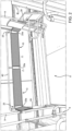
figure 2 is a perspective view of a space inside the bus offigure 1 comprising a backrest according to the invention; -
figure 3 is a perspective, exploded view of a backrest according to the invention; -
figure 4 is an enlarged, perspective view of part of the backrest offigure 3 ; and -
figures 5 and 6 are cross section views of the backrest offigure 3 . -
Figure 1 shows a known bus 1 comprising a plurality ofwalls 2, a pair of side walls, a front wall and a rear wall, a floor 3 and a ceiling (not shown), which delimit an inner space 4 of the vehicle 1 where passengers can seat or stand after having accessed the vehicle through a plurality ofdoors 5. - The bus 1 usually comprises a plurality of
seats 6 arranged inside the space 4 and defining an aisle 7 where passengers can walk in order to go get seated on theseats 6. The bus 1 further comprises anarea 8 communicating with the aisle 7 and configured to accommodate disabled people and/or passengers transporting large elements, for example suitcases or strollers. - The bus 1 can also comprise
support columns 9, against which a passenger can rest during the ride. Thearea 8 comprises at least twocolumns 9 along the aisle 7, one column at the left end and the other one at the right end of thearea 8. - The
area 8 also comprises abackrest 10, which is configured to allow passengers to rest against it for the duration of the ride. - According to the invention, the
backrest 10 basically comprises a profiledelement 11, which is configured to directly fasten thebackrest 10 to one of thewalls 2, and asupport element 12, which is supported by the profiledelement 11 and is configured to allow a passenger to rest against it. The profiledelement 11 can be fastened to thewall 2 in a known manner, for example through threaded means. - The profiled
element 11 has a substantially "C"-shaped cross section and comprises anupper portion 11a, which is configured to interact with anupper portion 12a of thesupport element 12, alower portion 11b, which is configured to interact with alower portion 12b of thesupport element 12, and aside portion 11c, which extends between theupper portion 11a and thelower portion 11b. - The profiled
element 11 is made of a metal material, preferably an aluminium alloy. Theportions - The
support element 12 has a substantially "C"-shaped cross section and comprises anupper portion 12a, which is configured to interact with theupper portion 11a of the profiledelement 11, alower portion 12b, which is configured to interact with alower portion 11b of the profiledelement 11, and aside portion 12c, which extends between theupper portion 12a and thelower portion 12b. Theside portion 12c preferably has a substantially rectangular cross section. - The
support element 12 is preferably made of a deformable material; more preferably, theelement 12 comprises anouter layer 14a, for example made of cloth or leather, which covers adeformable core 14b, for example made of a polymer foam. - The profiled
element 11 and thesupport element 12 are arranged in front of one another, thus defining a gap between one another. The total thickness of the profiledelement 11 and of thesupport element 12 coupled together is smaller than or, preferably, equal to 50 mm. - The
side portion 11c can also comprise aflange 13, which extends from theside portion 11c into the gap towards thesupport element 12, so as to interact, through contact, with theside portion 12c of theelement 12. Theflange 13 preferably is perpendicular to thesupport element 12. Theflange 13 is configured to prevent thesupport element 12 from bending on the profiledelement 11. - The
side portion 11c can further comprise at least oneguide 15, which is configured to allow the profiledelement 11 to be connected to an additional profiledelement 11, as described more in detail below. In the example described herein, the profiledelement 11 comprises twoguides 15, which are arranged under and above theflange 13, respectively. - The
flange 13 and theguides 15 are arranged on the side of the profiledelement 11 in front of thesupport element 12; on the contrary, the opposite side of thesupport element 12 does not comprise any fastening element and defines a substantiallyflat surface 11c, which can comprise a desired surface finish. - The upper portions of the profiled
element 11 and of thesupport element 12 interact with one another thanks to ashape coupling 17. Theshape coupling 17 preferably is reversible and allows thesupport element 12 to be coupled to and uncoupled from the profiledelement 11 depending on the needs. Theshape coupling 17 can be obtained through atab 18, which extends from theupper portion 12a of thesupport element 12, preferably has the shape of a hook and is configured to be inserted into agroove 19, which is obtained on theupper portion 11a of the profiledelement 11. - Similarly, the lower portions of the profiled
element 11 and of thesupport element 12 interact with one another thanks to amechanical coupling 20; themechanical coupling 20 preferably is reversible and allows thesupport element 12 to be coupled to and uncoupled from the profiledelement 11 depending on the needs. Themechanical coupling 20 can be obtained by means of a threadedelement 21, which is configured to join the tab extending from thelower portion 12b of thesupport element 12 to thelower portion 11b of the profiledelement 11. - The
backrest 10 preferably is inclined relative to the vertical by 5°. Furthermore, thesupport element 12 vertically extends more than theprofiled element 11, so that theupper portion 12a of thesupport element 12 rises above theupper portion 11a of theprofiled element 11 and so that, similarly, thelower portion 12b of thesupport element 12 rises above thelower portion 11b of theprofiled element 11. In the way, thereversible couplings support element 12. - The
backrest 10 can also comprise joiningelements 25, which are configured to connect twobackrests 10 to one another, so as to build a perimeter of thebackrest 10 having a desired shape. - The joining
elements 25 basically each comprise a profiledelement 25a having a cross section with a shape that is complementary to the shape of the profiledelement 11, so as to be completely coupled inside the latter. - In the example described herein, see
figure 3 , fourbackrests 10 are connected to one another so as to delimit a "C" shape corresponding to part of the perimeter of thearea 8. Therefore, the joiningelements 25 are two angle profiledelements 25a, which are configured to perpendicularly connect twobackrests 10 to one another, and a flat profiledelement 25a, which is configured to connect tobackrests 10 to one another in a parallel manner. The joiningelements 25 are further configured to conceal from view the fastening of the profiledelement 11 on thewall 2 and the fastening of a handrail, as described more in detail below. - The joining
elements 25 comprise at least one flange , which can be connected to arespective guide 15 of the profiledelement 11 so as to fasten the latter to the joiningelement 25. In the example described herein, a joiningelement 25 comprises two flanges , which are configured to be connected to the twoguides 15 supported by the profiledelement 11. The connection can be obtained by means of coupling means, for example threaded elements. - The
backrest 10 can further compriseterminal elements 28, which are configured to be connected to a side end of abackrest 10 so as to close the gap defined between the profiledelement 11 and thesupport element 12 and connect thebackrest 10 to one of thecolumns 9. - The
terminal elements 28 basically comprise acover 28a having a substantiallyrectangular base 29 and anedge 30 extending from thebase 29 at least along part of the perimeter thereof. The shape of thebase 29 and of thecorresponding edge 30 is complementary to the shape of the profiledelement 11 so as to be totally coupled inside the latter. - The
base 29 comprises an outer surface 29a, which is configured to allow theterminal element 28 to be coupled to one of the support columns of the vehicle 1. This coupling is obtained by means of a shape coupling between the outer surface 29a and thesupport columns 9 of the vehicle 1. - This shape coupling preferably comprises at least one lowered
surface 32, which is lowered relative to the outer surface 29a of thebase 29 and has a cross section that is complementary to the outer surface of thecolumns 9. There preferably are two loweredportions 32, which are arranged so as to cross one another, more preferably so as to cross one another in an "X" shape in a symmetrical manner and with a 5° angle between one another; in this way, the sameterminal element 28 can be equally used at a left or right end of thebackrest 10 in order to connect the latter to acolumn 9. - A
terminal element 28 can be fastened to therespective column 9 thanks to a threaded element (not shown) configured to go through ahole 33 made at the bottom of said at least one loweredportion 32 and through a hole (not shown) made at the front in thecolumn 9. - The
backrest 10 can further comprise acolumn 40, which can be connected to at least one between the profiledportion 11 and the joiningelements 25 and extends above thebackrest 10 along at least part of the perimeter thereof. Thecolumn 40 preferably is horizontal and can be fastened to theupper portion 11a of the profiledelement 11 thanks to a threaded element. Part of thecolumn 40 can advantageously be manufactured so as to be integral to the joiningelements 25. - Owing to the above, the advantages of a
backrest 10 according to the invention are evident. - The
backrest 10 according to the invention can be directly fastened to theside wall 2 of the vehicle. By so doing, its dimensions are reduced and the backrests takes up less than 50 mm. - Furthermore, the
backrest 10 comprises asupport element 12, which can easily be uncoupled from the profiledelement 11 in order to be replaced. Its connection to the profiledelement 11 is concealed by thesupport element 12. In this way, the fastening is concealed from the passengers' view and, therefore, thebackrest 10 has a better appearance. - The
outer surface 11b of the profiledelement 11, which is visible, does not comprise any fastening element and can comprise a desired surface finish. - The joining
element 25 allowadditional backrests 10 to be connected to afirst backrest 10 in a simple and versatile manner. - Furthermore, the
terminal elements 28 allow the gap between the profiledelement 11 and thesupport element 12 to be closed and thebackrest 10 to be connected to acolumn 9. - Finally, the
backrest 10 according to the invention can clearly be subjected to changes and variants, which, though, do not go beyond the scope of protection set forth in the claims. - For example, the shape or the material of the profiled
element 11 and/or of thesupport element 12 could change.
Claims (11)
- A backrest (10) for a vehicle (1) for the public transport of passengers, said backrest (10) comprising a fastening element (11) configured to be directly fixed to a wall (2) of said vehicle (1) and a support element (12) supported by said fastening element (11), wherein said fastening element (11) is a profiled element and said support element (12) comprises an outer layer (14a) which covers a deformable core (14b),
characterised in that said backrest (10) comprises at least one between:- at least one terminal element (28) configured to close a gap defined between said fastening element (11) and said support element (12), wherein said terminal element (28) is configured to connect said backrest (10) to a column (9) of said vehicle (1) and- at least one joining element (25) configured to connect two backrests (10) together, wherein said joining element (25) comprises a profiled element (25a), wherein said joining element (25) is configured to connect two fastening elements (11) together and to conceal the fastening of other elements (40) to said fastening element (11) and of said fastening element (11) to said wall (2). - The backrest according to claim 1, wherein the thickness of said backrest (10) is less than 50 mm.
- The backrest according to claim 1 or 2, wherein said fastening element (11) and said support element (12) comprise respective upper portions (11a, 12a) and lower portions (11b, 12b) each configured to interact with one another to define reversible couplings of said support element (12) on said fastening element (11).
- The backrest according to claim 3, wherein at least one of said upper portions (11a, 12a) and said lower portions (11b, 12b) are coupled to one another by means of a shape coupling (17).
- The backrest according to claim 4, wherein said shape coupling (17) comprises a tab (18), which is supported either by the upper portion (11a) of said fastening element (11) or by the upper portion (12a) of said support element (12) and is configured to be inserted in a groove (19) provided in the other one of either the upper portion (11a) of said fastening element (11) or the upper portion (12a) of said support element (12).
- The backrest according to claim 3, wherein at least one of said upper portions (11a, 12a) and said lower portions (11b, 12b) are coupled by means of a mechanical coupling (20).
- The backrest according to claim 6, wherein said mechanical coupling (20) is a threaded coupling.
- The backrest according to one of the claims from 3 to 7, wherein said reversible couplings are concealed from view by said support element (12).
- The backrest according to any of the preceding claims wherein said terminal element (28) comprises lowered portions (32) having a section complementary to an outer surface of a column (9) of said vehicle (1).
- The backrest according to claim 9, wherein said lowered portions (32) are two in number and are crossed in an "X" shape, defining an angle of at least 5° between one another.
- The backrest according to one of the preceding claims, wherein said fastening element (11) carries an element (13) extending towards said support element (12) and cooperating with the latter in contact, so as to prevent it from collapsing when a load is applied to said support element (12) in the direction of said fastening element (11).
Applications Claiming Priority (2)
| Application Number | Priority Date | Filing Date | Title |
|---|---|---|---|
| IT102018000004098A IT201800004098A1 (en) | 2018-03-29 | 2018-03-29 | BACKREST FOR VEHICLE |
| EP19166389.7A EP3546284B1 (en) | 2018-03-29 | 2019-03-29 | Backrest for a vehicle |
Related Parent Applications (2)
| Application Number | Title | Priority Date | Filing Date |
|---|---|---|---|
| EP19166389.7A Division EP3546284B1 (en) | 2018-03-29 | 2019-03-29 | Backrest for a vehicle |
| EP19166389.7A Division-Into EP3546284B1 (en) | 2018-03-29 | 2019-03-29 | Backrest for a vehicle |
Publications (2)
| Publication Number | Publication Date |
|---|---|
| EP3939827A1 EP3939827A1 (en) | 2022-01-19 |
| EP3939827B1 true EP3939827B1 (en) | 2024-06-26 |
Family
ID=62597985
Family Applications (2)
| Application Number | Title | Priority Date | Filing Date |
|---|---|---|---|
| EP21196153.7A Active EP3939827B1 (en) | 2018-03-29 | 2019-03-29 | Backrest for a vehicle |
| EP19166389.7A Active EP3546284B1 (en) | 2018-03-29 | 2019-03-29 | Backrest for a vehicle |
Family Applications After (1)
| Application Number | Title | Priority Date | Filing Date |
|---|---|---|---|
| EP19166389.7A Active EP3546284B1 (en) | 2018-03-29 | 2019-03-29 | Backrest for a vehicle |
Country Status (3)
| Country | Link |
|---|---|
| EP (2) | EP3939827B1 (en) |
| ES (1) | ES2909100T3 (en) |
| IT (1) | IT201800004098A1 (en) |
Family Cites Families (5)
| Publication number | Priority date | Publication date | Assignee | Title |
|---|---|---|---|---|
| FR2798331B1 (en) * | 1999-09-10 | 2001-11-16 | Renault | ARRANGEMENT OF A SEAT FOR A MOTOR VEHICLE FOR TRANSPORTATION AND A BENCH COMPRISING SUCH AN ARRANGEMENT |
| JP4628976B2 (en) * | 2006-02-28 | 2011-02-09 | 財団法人鉄道総合技術研究所 | Multipurpose storage device for railway vehicles |
| FR2924991B1 (en) * | 2007-12-13 | 2010-02-19 | Compin | PILOT SUPPORT DEVICE |
| US8579350B2 (en) * | 2009-12-14 | 2013-11-12 | Kustom Seating Unlimited, Ltd. | Modular transit system |
| JP6528277B2 (en) * | 2015-07-28 | 2019-06-12 | 三菱重工エンジニアリング株式会社 | vehicle |
-
2018
- 2018-03-29 IT IT102018000004098A patent/IT201800004098A1/en unknown
-
2019
- 2019-03-29 EP EP21196153.7A patent/EP3939827B1/en active Active
- 2019-03-29 ES ES19166389T patent/ES2909100T3/en active Active
- 2019-03-29 EP EP19166389.7A patent/EP3546284B1/en active Active
Also Published As
| Publication number | Publication date |
|---|---|
| EP3939827A1 (en) | 2022-01-19 |
| EP3546284A1 (en) | 2019-10-02 |
| ES2909100T3 (en) | 2022-05-05 |
| IT201800004098A1 (en) | 2019-09-29 |
| EP3546284B1 (en) | 2022-01-12 |
Similar Documents
| Publication | Publication Date | Title |
|---|---|---|
| US3485006A (en) | Connection of a girder with one or more bars angularly positioned on it | |
| JP5870892B2 (en) | Vehicle seat | |
| US6454345B1 (en) | Rail vehicle body | |
| US9452693B2 (en) | Seat | |
| US10144324B2 (en) | Seat back structure | |
| JP6047278B2 (en) | Capsule bed | |
| US9463747B2 (en) | Compartment panel assembly and vehicle employing the same | |
| EP3939827B1 (en) | Backrest for a vehicle | |
| US8272679B2 (en) | Door spacer block design for side impact protection | |
| US9586534B2 (en) | Vehicle trim structure | |
| US20140042791A1 (en) | Seat | |
| EP3418241B1 (en) | An elevator car | |
| MXPA97003559A (en) | Seat for publ transport vehicles | |
| US20080252131A1 (en) | Automotive vehicle seat back and method of making same | |
| CN104512483A (en) | Understructure for a motor vehicle | |
| EP2008547B1 (en) | Support panel for furnishings in commercial vehicles, in particular for shelving, and a method for the manufacture thereof | |
| US20220126734A1 (en) | Composite seat back | |
| US12384228B2 (en) | Vehicle cabin partition structure | |
| US9517743B2 (en) | Vehicle interior structure | |
| EP3418240B1 (en) | An elevator car wall | |
| US6247743B1 (en) | Coverlet for the rear portion of a vehicle having a roll bar | |
| US11958387B2 (en) | Seating in a vehicle | |
| JP3223906U (en) | Sleeve dividers for railway vehicles | |
| AU2019383286B2 (en) | Frame for seats in public transport vehicles | |
| CN222202691U (en) | Side wall rear section assembly and car |
Legal Events
| Date | Code | Title | Description |
|---|---|---|---|
| PUAI | Public reference made under article 153(3) epc to a published international application that has entered the european phase |
Free format text: ORIGINAL CODE: 0009012 |
|
| STAA | Information on the status of an ep patent application or granted ep patent |
Free format text: STATUS: THE APPLICATION HAS BEEN PUBLISHED |
|
| AC | Divisional application: reference to earlier application |
Ref document number: 3546284 Country of ref document: EP Kind code of ref document: P |
|
| AK | Designated contracting states |
Kind code of ref document: A1 Designated state(s): AL AT BE BG CH CY CZ DE DK EE ES FI FR GB GR HR HU IE IS IT LI LT LU LV MC MK MT NL NO PL PT RO RS SE SI SK SM TR |
|
| STAA | Information on the status of an ep patent application or granted ep patent |
Free format text: STATUS: REQUEST FOR EXAMINATION WAS MADE |
|
| 17P | Request for examination filed |
Effective date: 20220704 |
|
| RBV | Designated contracting states (corrected) |
Designated state(s): AL AT BE BG CH CY CZ DE DK EE ES FI FR GB GR HR HU IE IS IT LI LT LU LV MC MK MT NL NO PL PT RO RS SE SI SK SM TR |
|
| GRAP | Despatch of communication of intention to grant a patent |
Free format text: ORIGINAL CODE: EPIDOSNIGR1 |
|
| STAA | Information on the status of an ep patent application or granted ep patent |
Free format text: STATUS: GRANT OF PATENT IS INTENDED |
|
| INTG | Intention to grant announced |
Effective date: 20240124 |
|
| P01 | Opt-out of the competence of the unified patent court (upc) registered |
Effective date: 20240201 |
|
| GRAS | Grant fee paid |
Free format text: ORIGINAL CODE: EPIDOSNIGR3 |
|
| GRAA | (expected) grant |
Free format text: ORIGINAL CODE: 0009210 |
|
| STAA | Information on the status of an ep patent application or granted ep patent |
Free format text: STATUS: THE PATENT HAS BEEN GRANTED |
|
| AC | Divisional application: reference to earlier application |
Ref document number: 3546284 Country of ref document: EP Kind code of ref document: P |
|
| AK | Designated contracting states |
Kind code of ref document: B1 Designated state(s): AL AT BE BG CH CY CZ DE DK EE ES FI FR GB GR HR HU IE IS IT LI LT LU LV MC MK MT NL NO PL PT RO RS SE SI SK SM TR |
|
| REG | Reference to a national code |
Ref country code: GB Ref legal event code: FG4D |
|
| REG | Reference to a national code |
Ref country code: CH Ref legal event code: EP |
|
| REG | Reference to a national code |
Ref country code: DE Ref legal event code: R096 Ref document number: 602019054430 Country of ref document: DE |
|
| PG25 | Lapsed in a contracting state [announced via postgrant information from national office to epo] |
Ref country code: BG Free format text: LAPSE BECAUSE OF FAILURE TO SUBMIT A TRANSLATION OF THE DESCRIPTION OR TO PAY THE FEE WITHIN THE PRESCRIBED TIME-LIMIT Effective date: 20240626 |
|
| PG25 | Lapsed in a contracting state [announced via postgrant information from national office to epo] |
Ref country code: FI Free format text: LAPSE BECAUSE OF FAILURE TO SUBMIT A TRANSLATION OF THE DESCRIPTION OR TO PAY THE FEE WITHIN THE PRESCRIBED TIME-LIMIT Effective date: 20240626 Ref country code: HR Free format text: LAPSE BECAUSE OF FAILURE TO SUBMIT A TRANSLATION OF THE DESCRIPTION OR TO PAY THE FEE WITHIN THE PRESCRIBED TIME-LIMIT Effective date: 20240626 |
|
| REG | Reference to a national code |
Ref country code: LT Ref legal event code: MG9D |
|
| PG25 | Lapsed in a contracting state [announced via postgrant information from national office to epo] |
Ref country code: GR Free format text: LAPSE BECAUSE OF FAILURE TO SUBMIT A TRANSLATION OF THE DESCRIPTION OR TO PAY THE FEE WITHIN THE PRESCRIBED TIME-LIMIT Effective date: 20240927 |
|
| PG25 | Lapsed in a contracting state [announced via postgrant information from national office to epo] |
Ref country code: LV Free format text: LAPSE BECAUSE OF FAILURE TO SUBMIT A TRANSLATION OF THE DESCRIPTION OR TO PAY THE FEE WITHIN THE PRESCRIBED TIME-LIMIT Effective date: 20240626 |
|
| REG | Reference to a national code |
Ref country code: NL Ref legal event code: MP Effective date: 20240626 |
|
| PG25 | Lapsed in a contracting state [announced via postgrant information from national office to epo] |
Ref country code: NO Free format text: LAPSE BECAUSE OF FAILURE TO SUBMIT A TRANSLATION OF THE DESCRIPTION OR TO PAY THE FEE WITHIN THE PRESCRIBED TIME-LIMIT Effective date: 20240926 Ref country code: LV Free format text: LAPSE BECAUSE OF FAILURE TO SUBMIT A TRANSLATION OF THE DESCRIPTION OR TO PAY THE FEE WITHIN THE PRESCRIBED TIME-LIMIT Effective date: 20240626 Ref country code: HR Free format text: LAPSE BECAUSE OF FAILURE TO SUBMIT A TRANSLATION OF THE DESCRIPTION OR TO PAY THE FEE WITHIN THE PRESCRIBED TIME-LIMIT Effective date: 20240626 Ref country code: GR Free format text: LAPSE BECAUSE OF FAILURE TO SUBMIT A TRANSLATION OF THE DESCRIPTION OR TO PAY THE FEE WITHIN THE PRESCRIBED TIME-LIMIT Effective date: 20240927 Ref country code: FI Free format text: LAPSE BECAUSE OF FAILURE TO SUBMIT A TRANSLATION OF THE DESCRIPTION OR TO PAY THE FEE WITHIN THE PRESCRIBED TIME-LIMIT Effective date: 20240626 Ref country code: BG Free format text: LAPSE BECAUSE OF FAILURE TO SUBMIT A TRANSLATION OF THE DESCRIPTION OR TO PAY THE FEE WITHIN THE PRESCRIBED TIME-LIMIT Effective date: 20240626 Ref country code: RS Free format text: LAPSE BECAUSE OF FAILURE TO SUBMIT A TRANSLATION OF THE DESCRIPTION OR TO PAY THE FEE WITHIN THE PRESCRIBED TIME-LIMIT Effective date: 20240926 |
|
| PG25 | Lapsed in a contracting state [announced via postgrant information from national office to epo] |
Ref country code: NL Free format text: LAPSE BECAUSE OF FAILURE TO SUBMIT A TRANSLATION OF THE DESCRIPTION OR TO PAY THE FEE WITHIN THE PRESCRIBED TIME-LIMIT Effective date: 20240626 |
|
| REG | Reference to a national code |
Ref country code: AT Ref legal event code: MK05 Ref document number: 1697446 Country of ref document: AT Kind code of ref document: T Effective date: 20240626 |
|
| PG25 | Lapsed in a contracting state [announced via postgrant information from national office to epo] |
Ref country code: NL Free format text: LAPSE BECAUSE OF FAILURE TO SUBMIT A TRANSLATION OF THE DESCRIPTION OR TO PAY THE FEE WITHIN THE PRESCRIBED TIME-LIMIT Effective date: 20240626 |
|
| PG25 | Lapsed in a contracting state [announced via postgrant information from national office to epo] |
Ref country code: PT Free format text: LAPSE BECAUSE OF FAILURE TO SUBMIT A TRANSLATION OF THE DESCRIPTION OR TO PAY THE FEE WITHIN THE PRESCRIBED TIME-LIMIT Effective date: 20241028 |
|
| PG25 | Lapsed in a contracting state [announced via postgrant information from national office to epo] |
Ref country code: PT Free format text: LAPSE BECAUSE OF FAILURE TO SUBMIT A TRANSLATION OF THE DESCRIPTION OR TO PAY THE FEE WITHIN THE PRESCRIBED TIME-LIMIT Effective date: 20241028 |
|
| PG25 | Lapsed in a contracting state [announced via postgrant information from national office to epo] |
Ref country code: PL Free format text: LAPSE BECAUSE OF FAILURE TO SUBMIT A TRANSLATION OF THE DESCRIPTION OR TO PAY THE FEE WITHIN THE PRESCRIBED TIME-LIMIT Effective date: 20240626 |
|
| PG25 | Lapsed in a contracting state [announced via postgrant information from national office to epo] |
Ref country code: EE Free format text: LAPSE BECAUSE OF FAILURE TO SUBMIT A TRANSLATION OF THE DESCRIPTION OR TO PAY THE FEE WITHIN THE PRESCRIBED TIME-LIMIT Effective date: 20240626 |
|
| PG25 | Lapsed in a contracting state [announced via postgrant information from national office to epo] |
Ref country code: AT Free format text: LAPSE BECAUSE OF FAILURE TO SUBMIT A TRANSLATION OF THE DESCRIPTION OR TO PAY THE FEE WITHIN THE PRESCRIBED TIME-LIMIT Effective date: 20240626 Ref country code: IS Free format text: LAPSE BECAUSE OF FAILURE TO SUBMIT A TRANSLATION OF THE DESCRIPTION OR TO PAY THE FEE WITHIN THE PRESCRIBED TIME-LIMIT Effective date: 20241026 |
|
| PG25 | Lapsed in a contracting state [announced via postgrant information from national office to epo] |
Ref country code: CZ Free format text: LAPSE BECAUSE OF FAILURE TO SUBMIT A TRANSLATION OF THE DESCRIPTION OR TO PAY THE FEE WITHIN THE PRESCRIBED TIME-LIMIT Effective date: 20240626 |
|
| PG25 | Lapsed in a contracting state [announced via postgrant information from national office to epo] |
Ref country code: RO Free format text: LAPSE BECAUSE OF FAILURE TO SUBMIT A TRANSLATION OF THE DESCRIPTION OR TO PAY THE FEE WITHIN THE PRESCRIBED TIME-LIMIT Effective date: 20240626 Ref country code: SK Free format text: LAPSE BECAUSE OF FAILURE TO SUBMIT A TRANSLATION OF THE DESCRIPTION OR TO PAY THE FEE WITHIN THE PRESCRIBED TIME-LIMIT Effective date: 20240626 |
|
| PG25 | Lapsed in a contracting state [announced via postgrant information from national office to epo] |
Ref country code: ES Free format text: LAPSE BECAUSE OF FAILURE TO SUBMIT A TRANSLATION OF THE DESCRIPTION OR TO PAY THE FEE WITHIN THE PRESCRIBED TIME-LIMIT Effective date: 20240626 Ref country code: SM Free format text: LAPSE BECAUSE OF FAILURE TO SUBMIT A TRANSLATION OF THE DESCRIPTION OR TO PAY THE FEE WITHIN THE PRESCRIBED TIME-LIMIT Effective date: 20240626 |
|
| PG25 | Lapsed in a contracting state [announced via postgrant information from national office to epo] |
Ref country code: SM Free format text: LAPSE BECAUSE OF FAILURE TO SUBMIT A TRANSLATION OF THE DESCRIPTION OR TO PAY THE FEE WITHIN THE PRESCRIBED TIME-LIMIT Effective date: 20240626 Ref country code: SK Free format text: LAPSE BECAUSE OF FAILURE TO SUBMIT A TRANSLATION OF THE DESCRIPTION OR TO PAY THE FEE WITHIN THE PRESCRIBED TIME-LIMIT Effective date: 20240626 Ref country code: RO Free format text: LAPSE BECAUSE OF FAILURE TO SUBMIT A TRANSLATION OF THE DESCRIPTION OR TO PAY THE FEE WITHIN THE PRESCRIBED TIME-LIMIT Effective date: 20240626 Ref country code: PL Free format text: LAPSE BECAUSE OF FAILURE TO SUBMIT A TRANSLATION OF THE DESCRIPTION OR TO PAY THE FEE WITHIN THE PRESCRIBED TIME-LIMIT Effective date: 20240626 Ref country code: IS Free format text: LAPSE BECAUSE OF FAILURE TO SUBMIT A TRANSLATION OF THE DESCRIPTION OR TO PAY THE FEE WITHIN THE PRESCRIBED TIME-LIMIT Effective date: 20241026 Ref country code: ES Free format text: LAPSE BECAUSE OF FAILURE TO SUBMIT A TRANSLATION OF THE DESCRIPTION OR TO PAY THE FEE WITHIN THE PRESCRIBED TIME-LIMIT Effective date: 20240626 Ref country code: EE Free format text: LAPSE BECAUSE OF FAILURE TO SUBMIT A TRANSLATION OF THE DESCRIPTION OR TO PAY THE FEE WITHIN THE PRESCRIBED TIME-LIMIT Effective date: 20240626 Ref country code: CZ Free format text: LAPSE BECAUSE OF FAILURE TO SUBMIT A TRANSLATION OF THE DESCRIPTION OR TO PAY THE FEE WITHIN THE PRESCRIBED TIME-LIMIT Effective date: 20240626 Ref country code: AT Free format text: LAPSE BECAUSE OF FAILURE TO SUBMIT A TRANSLATION OF THE DESCRIPTION OR TO PAY THE FEE WITHIN THE PRESCRIBED TIME-LIMIT Effective date: 20240626 |
|
| REG | Reference to a national code |
Ref country code: DE Ref legal event code: R097 Ref document number: 602019054430 Country of ref document: DE |
|
| PG25 | Lapsed in a contracting state [announced via postgrant information from national office to epo] |
Ref country code: DK Free format text: LAPSE BECAUSE OF FAILURE TO SUBMIT A TRANSLATION OF THE DESCRIPTION OR TO PAY THE FEE WITHIN THE PRESCRIBED TIME-LIMIT Effective date: 20240626 |
|
| PLBE | No opposition filed within time limit |
Free format text: ORIGINAL CODE: 0009261 |
|
| STAA | Information on the status of an ep patent application or granted ep patent |
Free format text: STATUS: NO OPPOSITION FILED WITHIN TIME LIMIT |
|
| 26N | No opposition filed |
Effective date: 20250327 |
|
| PG25 | Lapsed in a contracting state [announced via postgrant information from national office to epo] |
Ref country code: SE Free format text: LAPSE BECAUSE OF FAILURE TO SUBMIT A TRANSLATION OF THE DESCRIPTION OR TO PAY THE FEE WITHIN THE PRESCRIBED TIME-LIMIT Effective date: 20240626 |
|
| PG25 | Lapsed in a contracting state [announced via postgrant information from national office to epo] |
Ref country code: MC Free format text: LAPSE BECAUSE OF FAILURE TO SUBMIT A TRANSLATION OF THE DESCRIPTION OR TO PAY THE FEE WITHIN THE PRESCRIBED TIME-LIMIT Effective date: 20240626 |
|
| REG | Reference to a national code |
Ref country code: CH Ref legal event code: H13 Free format text: ST27 STATUS EVENT CODE: U-0-0-H10-H13 (AS PROVIDED BY THE NATIONAL OFFICE) Effective date: 20251023 |
|
| PG25 | Lapsed in a contracting state [announced via postgrant information from national office to epo] |
Ref country code: LU Free format text: LAPSE BECAUSE OF NON-PAYMENT OF DUE FEES Effective date: 20250329 |
|
| GBPC | Gb: european patent ceased through non-payment of renewal fee |
Effective date: 20250329 |
|
| REG | Reference to a national code |
Ref country code: BE Ref legal event code: MM Effective date: 20250331 |
|
| PG25 | Lapsed in a contracting state [announced via postgrant information from national office to epo] |
Ref country code: GB Free format text: LAPSE BECAUSE OF NON-PAYMENT OF DUE FEES Effective date: 20250329 |
|
| PG25 | Lapsed in a contracting state [announced via postgrant information from national office to epo] |
Ref country code: BE Free format text: LAPSE BECAUSE OF NON-PAYMENT OF DUE FEES Effective date: 20250331 |
|
| PG25 | Lapsed in a contracting state [announced via postgrant information from national office to epo] |
Ref country code: CH Free format text: LAPSE BECAUSE OF NON-PAYMENT OF DUE FEES Effective date: 20250331 |
|
| PG25 | Lapsed in a contracting state [announced via postgrant information from national office to epo] |
Ref country code: IE Free format text: LAPSE BECAUSE OF NON-PAYMENT OF DUE FEES Effective date: 20250329 |
|
| PGFP | Annual fee paid to national office [announced via postgrant information from national office to epo] |
Ref country code: DE Payment date: 20260320 Year of fee payment: 8 |
|
| PGFP | Annual fee paid to national office [announced via postgrant information from national office to epo] |
Ref country code: IT Payment date: 20260311 Year of fee payment: 8 |
|
| PGFP | Annual fee paid to national office [announced via postgrant information from national office to epo] |
Ref country code: FR Payment date: 20260323 Year of fee payment: 8 |