EP3939794A1 - Liquid storage container - Google Patents
Liquid storage container Download PDFInfo
- Publication number
- EP3939794A1 EP3939794A1 EP21185107.6A EP21185107A EP3939794A1 EP 3939794 A1 EP3939794 A1 EP 3939794A1 EP 21185107 A EP21185107 A EP 21185107A EP 3939794 A1 EP3939794 A1 EP 3939794A1
- Authority
- EP
- European Patent Office
- Prior art keywords
- storage container
- liquid
- liquid storage
- sealing portion
- discharge port
- Prior art date
- Legal status (The legal status is an assumption and is not a legal conclusion. Google has not performed a legal analysis and makes no representation as to the accuracy of the status listed.)
- Granted
Links
Images




Classifications
-
- B—PERFORMING OPERATIONS; TRANSPORTING
- B41—PRINTING; LINING MACHINES; TYPEWRITERS; STAMPS
- B41J—TYPEWRITERS; SELECTIVE PRINTING MECHANISMS, i.e. MECHANISMS PRINTING OTHERWISE THAN FROM A FORME; CORRECTION OF TYPOGRAPHICAL ERRORS
- B41J2/00—Typewriters or selective printing mechanisms characterised by the printing or marking process for which they are designed
- B41J2/005—Typewriters or selective printing mechanisms characterised by the printing or marking process for which they are designed characterised by bringing liquid or particles selectively into contact with a printing material
- B41J2/01—Ink jet
- B41J2/17—Ink jet characterised by ink handling
- B41J2/175—Ink supply systems ; Circuit parts therefor
- B41J2/17596—Ink pumps, ink valves
-
- B—PERFORMING OPERATIONS; TRANSPORTING
- B41—PRINTING; LINING MACHINES; TYPEWRITERS; STAMPS
- B41J—TYPEWRITERS; SELECTIVE PRINTING MECHANISMS, i.e. MECHANISMS PRINTING OTHERWISE THAN FROM A FORME; CORRECTION OF TYPOGRAPHICAL ERRORS
- B41J2/00—Typewriters or selective printing mechanisms characterised by the printing or marking process for which they are designed
- B41J2/005—Typewriters or selective printing mechanisms characterised by the printing or marking process for which they are designed characterised by bringing liquid or particles selectively into contact with a printing material
- B41J2/01—Ink jet
- B41J2/17—Ink jet characterised by ink handling
- B41J2/175—Ink supply systems ; Circuit parts therefor
- B41J2/17503—Ink cartridges
- B41J2/17506—Refilling of the cartridge
- B41J2/17509—Whilst mounted in the printer
-
- B—PERFORMING OPERATIONS; TRANSPORTING
- B41—PRINTING; LINING MACHINES; TYPEWRITERS; STAMPS
- B41J—TYPEWRITERS; SELECTIVE PRINTING MECHANISMS, i.e. MECHANISMS PRINTING OTHERWISE THAN FROM A FORME; CORRECTION OF TYPOGRAPHICAL ERRORS
- B41J2/00—Typewriters or selective printing mechanisms characterised by the printing or marking process for which they are designed
- B41J2/005—Typewriters or selective printing mechanisms characterised by the printing or marking process for which they are designed characterised by bringing liquid or particles selectively into contact with a printing material
- B41J2/01—Ink jet
- B41J2/17—Ink jet characterised by ink handling
- B41J2/175—Ink supply systems ; Circuit parts therefor
- B41J2/17503—Ink cartridges
-
- B—PERFORMING OPERATIONS; TRANSPORTING
- B41—PRINTING; LINING MACHINES; TYPEWRITERS; STAMPS
- B41J—TYPEWRITERS; SELECTIVE PRINTING MECHANISMS, i.e. MECHANISMS PRINTING OTHERWISE THAN FROM A FORME; CORRECTION OF TYPOGRAPHICAL ERRORS
- B41J2/00—Typewriters or selective printing mechanisms characterised by the printing or marking process for which they are designed
- B41J2/005—Typewriters or selective printing mechanisms characterised by the printing or marking process for which they are designed characterised by bringing liquid or particles selectively into contact with a printing material
- B41J2/01—Ink jet
- B41J2/17—Ink jet characterised by ink handling
- B41J2/175—Ink supply systems ; Circuit parts therefor
-
- B—PERFORMING OPERATIONS; TRANSPORTING
- B41—PRINTING; LINING MACHINES; TYPEWRITERS; STAMPS
- B41J—TYPEWRITERS; SELECTIVE PRINTING MECHANISMS, i.e. MECHANISMS PRINTING OTHERWISE THAN FROM A FORME; CORRECTION OF TYPOGRAPHICAL ERRORS
- B41J2/00—Typewriters or selective printing mechanisms characterised by the printing or marking process for which they are designed
- B41J2/005—Typewriters or selective printing mechanisms characterised by the printing or marking process for which they are designed characterised by bringing liquid or particles selectively into contact with a printing material
- B41J2/01—Ink jet
- B41J2/17—Ink jet characterised by ink handling
- B41J2/175—Ink supply systems ; Circuit parts therefor
- B41J2/17503—Ink cartridges
- B41J2/17506—Refilling of the cartridge
-
- B—PERFORMING OPERATIONS; TRANSPORTING
- B41—PRINTING; LINING MACHINES; TYPEWRITERS; STAMPS
- B41J—TYPEWRITERS; SELECTIVE PRINTING MECHANISMS, i.e. MECHANISMS PRINTING OTHERWISE THAN FROM A FORME; CORRECTION OF TYPOGRAPHICAL ERRORS
- B41J2/00—Typewriters or selective printing mechanisms characterised by the printing or marking process for which they are designed
- B41J2/005—Typewriters or selective printing mechanisms characterised by the printing or marking process for which they are designed characterised by bringing liquid or particles selectively into contact with a printing material
- B41J2/01—Ink jet
- B41J2/17—Ink jet characterised by ink handling
- B41J2/175—Ink supply systems ; Circuit parts therefor
- B41J2/17503—Ink cartridges
- B41J2/17513—Inner structure
-
- B—PERFORMING OPERATIONS; TRANSPORTING
- B41—PRINTING; LINING MACHINES; TYPEWRITERS; STAMPS
- B41J—TYPEWRITERS; SELECTIVE PRINTING MECHANISMS, i.e. MECHANISMS PRINTING OTHERWISE THAN FROM A FORME; CORRECTION OF TYPOGRAPHICAL ERRORS
- B41J2/00—Typewriters or selective printing mechanisms characterised by the printing or marking process for which they are designed
- B41J2/005—Typewriters or selective printing mechanisms characterised by the printing or marking process for which they are designed characterised by bringing liquid or particles selectively into contact with a printing material
- B41J2/01—Ink jet
- B41J2/17—Ink jet characterised by ink handling
- B41J2/175—Ink supply systems ; Circuit parts therefor
- B41J2/17503—Ink cartridges
- B41J2/1752—Mounting within the printer
- B41J2/17523—Ink connection
-
- B—PERFORMING OPERATIONS; TRANSPORTING
- B41—PRINTING; LINING MACHINES; TYPEWRITERS; STAMPS
- B41J—TYPEWRITERS; SELECTIVE PRINTING MECHANISMS, i.e. MECHANISMS PRINTING OTHERWISE THAN FROM A FORME; CORRECTION OF TYPOGRAPHICAL ERRORS
- B41J2/00—Typewriters or selective printing mechanisms characterised by the printing or marking process for which they are designed
- B41J2/005—Typewriters or selective printing mechanisms characterised by the printing or marking process for which they are designed characterised by bringing liquid or particles selectively into contact with a printing material
- B41J2/01—Ink jet
- B41J2/17—Ink jet characterised by ink handling
- B41J2/175—Ink supply systems ; Circuit parts therefor
- B41J2/17503—Ink cartridges
- B41J2/17536—Protection of cartridges or parts thereof, e.g. tape
- B41J2/1754—Protection of cartridges or parts thereof, e.g. tape with means attached to the cartridge, e.g. protective cap
-
- B—PERFORMING OPERATIONS; TRANSPORTING
- B41—PRINTING; LINING MACHINES; TYPEWRITERS; STAMPS
- B41J—TYPEWRITERS; SELECTIVE PRINTING MECHANISMS, i.e. MECHANISMS PRINTING OTHERWISE THAN FROM A FORME; CORRECTION OF TYPOGRAPHICAL ERRORS
- B41J2/00—Typewriters or selective printing mechanisms characterised by the printing or marking process for which they are designed
- B41J2/005—Typewriters or selective printing mechanisms characterised by the printing or marking process for which they are designed characterised by bringing liquid or particles selectively into contact with a printing material
- B41J2/01—Ink jet
- B41J2/17—Ink jet characterised by ink handling
- B41J2/175—Ink supply systems ; Circuit parts therefor
- B41J2/17503—Ink cartridges
- B41J2/17553—Outer structure
-
- B—PERFORMING OPERATIONS; TRANSPORTING
- B41—PRINTING; LINING MACHINES; TYPEWRITERS; STAMPS
- B41J—TYPEWRITERS; SELECTIVE PRINTING MECHANISMS, i.e. MECHANISMS PRINTING OTHERWISE THAN FROM A FORME; CORRECTION OF TYPOGRAPHICAL ERRORS
- B41J29/00—Details of, or accessories for, typewriters or selective printing mechanisms not otherwise provided for
- B41J29/02—Framework
-
- B—PERFORMING OPERATIONS; TRANSPORTING
- B41—PRINTING; LINING MACHINES; TYPEWRITERS; STAMPS
- B41J—TYPEWRITERS; SELECTIVE PRINTING MECHANISMS, i.e. MECHANISMS PRINTING OTHERWISE THAN FROM A FORME; CORRECTION OF TYPOGRAPHICAL ERRORS
- B41J29/00—Details of, or accessories for, typewriters or selective printing mechanisms not otherwise provided for
- B41J29/12—Guards, shields or dust excluders
- B41J29/13—Cases or covers
Definitions
- the present disclosure relates to a liquid storage container configured to store liquid.
- liquid tanks used in liquid ejecting apparatuses such as inkjet printing apparatuses
- a liquid tank that can be replenished with liquid.
- the liquid tank can be replenished with the liquid from the liquid storage container through the discharge port.
- a valve with a slit is provided at a front end of the discharge port, and leakage of the liquid is thereby forcedly stopped (see Japanese Patent Laid-Open No. 2018-95277 (hereinafter, referred to as Document 1)).
- Document 1 describes a container which includes a discharge port main body and a cover capable of opening and closing the discharge port by covering it and in which a valve with a slit is provided inside the discharge port main body.
- Document 1 describes a configuration in which the discharge port is sealed with the cover before the cover is completely closed, and then, completely closing the cover causes a protrusion formed in the cover to be inserted into the valve and open the slit portion of the valve.
- the present invention in its first aspect provides a liquid storage container as specified in claims 1 to 15.
- Fig. 1 is a perspective view of an outer appearance of a liquid ejecting apparatus 1 in the embodiment.
- the liquid ejecting apparatus 1 illustrated in Fig. 1 is a serial inkjet printing apparatus.
- the liquid ejecting apparatus 1 illustrated in Fig. 1 includes a case 11 and liquid tanks 12 arranged inside the case 11. Each liquid tank 12 stores an ink that is liquid to be ejected to a print medium (not illustrated).
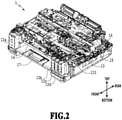
- Fig. 2 is a perspective view of an internal configuration of the liquid ejecting apparatus 1 illustrated in Fig. 1 .
- the liquid ejecting apparatus 1 includes a conveyance roller 13 used to convey the print medium (not illustrated), a carriage 15 provided with a print head 14 configured to eject the liquid, and a carriage motor 16 used to drive the carriage 15.
- the print medium is not limited to a particular medium as long as an image can be formed on the medium with the liquid ejected from the print head 14.
- paper, cloth, the label surfaces of optical discs, plastic sheets, OHP sheets or the like can be given as print media.
- the liquid is stored in the liquid tanks 12 and is supplied to the print head 14 via a liquid distribution passage 17 to be ejected from the print head 14.
- inks of four colors for example, cyan, magenta, yellow, and black
- four liquid tanks 12a to 12d for the respective colors that store the inks of the respective colors are provided as the liquid tanks 12.
- alphabets are added at the ends, for example, liquid tanks 12a to 12d.
- the liquid tank is referred to as the liquid tank 12.
- the liquid tanks 12a to 12d for the respective colors are arranged in a front face portion of the liquid ejecting apparatus 1 inside the case 11.
- Fig. 3A is an example of an enlarged perspective view of a portion of the liquid ejecting apparatus 1 illustrated in Fig. 1 in which the liquid tanks 12b to 12d are housed
- Fig. 3B is a plan view corresponding to the perspective view illustrated in Fig. 3A
- Each liquid tank 12 includes a liquid tank main body 121 used to store the liquid and a communication flow passage 122 communicating with a liquid storage chamber in the liquid tank main body 121.
- the liquid tank 12 includes a tank cover 123 (see Fig. 2 ) configured to be attachable to cover the communication flow passage 122 and seal the storage chamber in the liquid tank main body 121 in occasions other than an occasion of liquid replenishment.
- a discharge port of a liquid storage container 2 (see Fig. 4 ) is inserted into the communication flow passage 122 and the liquid is poured into the liquid tank 12.
- the liquid storage chamber is sealed with the tank cover 123 in occasions other than the occasion of liquid replenishment, and thus it is possible to reduce evaporation of the liquid in the liquid tank 12.
- the communication flow passage 122 includes two flow passages extending parallel to each other in the vertical direction in an interior thereof and is configured to allow the liquid in the liquid storage container 2 to be poured into the liquid tank by means of gas-liquid exchange.
- a socket 18 is provided in a portion of the liquid ejecting apparatus 1 where the discharge port of the liquid storage container 2 is to be inserted.
- the socket 18 is provided with protruding portions 19 protruding inward from an inner peripheral wall of the socket 18.
- the socket 18 is provided for each liquid tank 12, and the shapes of the protruding portions 19 vary among the sockets 18 to suppress erroneous insertion of the liquid container.
- the protruding portions 19 are rotationally symmetric by 180° with respect to the center axis of the communication flow passage 122.
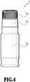
- Fig. 4 is an elevation view of an outer appearance of the liquid storage container 2 which is a liquid container used to replenish the liquid tank 12 with the liquid.
- the liquid storage container 2 in Fig. 4 includes a bottle 21 that is a storage portion (main body portion) configured to store the liquid, a nozzle 22 coupled to the bottle 21, and a cap 23 attachable to and detachable from the nozzle 22.
- the nozzle 22 is a discharge port member having a function of an outlet for the case where the liquid stored in the bottle 21 is discharged.
- the cap 23 is a cover portion that is attached to the nozzle 22 to shield the interior of the liquid storage container 2 (specifically, the bottle 21) from the outside air.
- Methods of coupling the bottle 21 and the nozzle 22 to each other include a method of sealing a space between the bottle 21 and the nozzle 22 by inserting a flexible part, a method of forming both of the bottle 21 and the nozzle 22 with resin parts and welding the two parts together, and the like.
- the bottle 21 and the nozzle 22 may be an integral part.
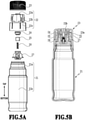
- Fig. 5A illustrates an example of a part configuration view of the liquid storage container 2 illustrated in Fig. 4 .
- Fig. 5B is a cross-sectional view in which the parts in the part configuration view of the liquid storage container 2 illustrated in Fig. 5A are coupled to one another.
- the bottle 21 of the liquid storage container 2 includes a bottle welding portion 21a formed in an upper portion and a liquid storage portion 21b formed in a lower portion.
- the nozzle 22 includes a discharge port 22a through which the liquid is discharged, a nozzle thread portion 22b in which a male thread structure is formed on the outside, and a nozzle welding portion 22c in which a welding surface is formed on the inside or a bottom surface.
- Polyethylene (PE), polypropylene (PP), and the like can be given as examples of the material forming the bottle 21.
- Polyethylene (PE), polypropylene (PP), and the like can be given as the material forming the nozzle 22.
- the nozzle 22 is joined to the bottle 21 by welding the nozzle welding portion 22c to the bottle welding portion 21a. In the case where the bottle 21 and the nozzle 22 are joined by being welded to each other, the bottle 21 and the nozzle 22 are preferably made of the same type of material.
- a seal 24 having an opening, a valve 25 configured to open and close the opening of the seal 24, a spring 26 configured to bias the valve 25, and a holder 27 configured to fix the spring 26 are included inside the nozzle 22.
- the communication flow passage 122 of the liquid tank 12 is inserted into an opening of the nozzle 22 of the liquid storage container 2.
- the nozzle 22 of the liquid storage container 2 is provided with recess portions configured to engage with the protruding portions 19 of the socket 18 in the liquid ejecting apparatus 1, and the liquid storage container 2 is aligned in the case where the communication flow passage 122 is inserted into the opening of the nozzle 22. Then, the liquid in the liquid storage container 2 is supplied to the storage chamber of the liquid tank main body 121 via the communication flow passage 122 by means of hydraulic head difference.
- the liquid storage container 2 includes two sealable portions (hereinafter, referred to as sealing portions).
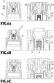
- Figs. 6A to 6C are explanatory views of the sealing portions. As illustrated in Fig. 6A , in a first sealing portion, sealing is achieved by fitting the cap 23 to the nozzle 22. As illustrated in Fig. 6B , in a second sealing portion, sealing is achieved by a valve structure in the nozzle 22. The sealing portions are described below.
- Fig. 6A is a cross-sectional view of an upper portion of the liquid storage container 2 in a state where the cap 23 is attached to the nozzle 22, and also illustrates an enlarged view of the upper portion.
- the first sealing portion is a portion in which a cap sealing portion 23b of the cap 23 is fitted to a nozzle sealing portion 22d that is part of the discharge port 22a of the nozzle 22 by attaching the cap 23 to the nozzle 22.
- a method of attaching the cap 23 to the nozzle 22 there is a method of screwing the cap 23 to the nozzle 22. Specifically, as illustrated in Figs.
- a fitting portion other than the sealing portion may be provided.
- a configuration such as an externally-fitted cover in which a cap 23 is fitted to the outside of a nozzle 22 or an internally-fitted cover in which a cap 23 is fitted to the inside of a nozzle 22.
- Fig. 6B is a cross-sectional view of the upper portion of the liquid storage container 2 in a state where no cap 23 is attached, and also illustrates an enlarged view of the upper portion.
- the second sealing portion is a portion of a liquid stop valve structure (valve structure) arranged inside the nozzle 22 of the liquid storage container 2.
- the seal 24 which is an orifice portion having an opening into which the communication flow passage 122 is to be inserted is arranged in a front end (upper end) of the nozzle 22.
- valve 25 which is a valve element of the liquid stop valve, is biased toward the opening with the spring 26, thereby the gap between the seal 24 and the valve 25 is closed, and the liquid storage container 2 is sealed.
- the spring 26 is used as a biasing mechanism, and the holder 27 fixed in an inner space of the nozzle 22 holds the spring 26.
- the seal 24 is formed of a flexible member made of rubber, elastomer, or the like.
- the liquid stop valve structure can maintain the interior of the liquid storage container 2 in the sealed state in the state where the cap 23 is removed from the nozzle 22.
- the communication flow passage 122 is inserted into the nozzle 22 through the opening of the seal 24, thereby opening the valve 25. Then, as described above, the liquid in the liquid storage container 2 is supplied to the storage chamber of the liquid tank main body 121 via the communication flow passage 122 by means of hydraulic head difference.
- the two sealing portions are configured to be temporarily simultaneously unsealed in cap-opening in which the cap 23 is removed from nozzle 22 and in cap-closing in which the cap is attached to the nozzle 22.
- This configuration allows the interior of the liquid storage container 2 to communicate with the atmosphere and can equalize the pressure inside the liquid storage container 2 with the outside air pressure. Details are described below.
- the first sealing portion is in a sealed state.
- a protrusion 23f arranged in the cap 23 is pushed in a direction opposite to the biasing direction of the valve 25 with the closing of the cap 23, and a gap is thereby formed between the seal 24 and the valve 25.
- the second sealing portion is in an unsealed state. Specifically, in the closed state of the cap 23, the first sealing portion is sealed, and the second sealing portion is unsealed.
- Fig. 6C is a cross-sectional view of an upper portion of the liquid storage container 2 in a state where the cap 23 has started to be opened from the state where the cap 23 is attached to the nozzle 22 illustrated in Fig. 6A , and also illustrates an enlarged view of the upper portion.
- the cap 23 moves upward from the closed state illustrated in Fig. 6A along with the cap-opening as illustrated in Fig. 6C .
- the cap sealing portion 23b and the nozzle sealing portion 22d separate from each other along with this movement of the cap 23, and the first sealing portion is unsealed. In the unsealing of the first sealing portion, the protrusion 23f arranged in the cap 23 is still at such a position that the protrusion 23f pushes the valve 25 as illustrated in Fig.
- the unsealed state of the second sealing portion is maintained. Accordingly, as illustrated in Fig. 6C , the second sealing portion and the first sealing portion can be simultaneously unsealed in unsealing the first sealing portion. Then, in the case where the cap 23 is further moved upward, the protrusion 23f completely separates from the valve 25 along with the movement of the cap 23, and as illustrated in Fig. 6B , the second sealing portion is sealed. Note that, also in the case where the cap 23 is closed from the open state, the protrusion 23f of the cap 23 pushes the valve 25 along with the movement of the cap 23, and the second sealing portion is unsealed.
- the unsealed state of the first sealing portion is maintained. Then, setting the cap 23 to the closed state sets the first sealing portion to the sealed state.
- the first sealing portion and the second sealing portion are simultaneously unsealed means that the first sealing portion and the second sealing portion are substantially simultaneously unsealed. In the case where unsealing of the first sealing portion causes the second sealing portion to be unsealed in conjunction, it means that both sealing portions are simultaneously unsealed.
- this configuration allows the interior of the liquid storage container 2 to communicate with the atmosphere and can equalize the pressure in the liquid storage container 2 with the outside air pressure. Accordingly, the occurrence of spraying-out of the liquid due to an increase in the internal pressure of the liquid storage container 2 can be suppressed in the case where the cap 23 is opened and the liquid tank main body 121 is replenished with the liquid from the liquid storage container 2. Moreover, it is possible to suppress the occurrence of overflow of the liquid from the liquid tank main body 121. Furthermore, since the second sealing portion maintains the interior of the liquid storage container 2 in the sealed state after the cap 23 is opened, the occurrence of leakage of the liquid can be suppressed even if the liquid storage container 2 is turned upside down.
- a rigid material such as polyethylene (PE) or polypropylene (PP) is used for the nozzle 22 and the cap 23 in the first sealing portion, and these parts are configured to be fitted to each other.
- PE polyethylene
- PP polypropylene
- a flexible material such as rubber or elastomer is used as the material forming the seal 24 in the second sealing portion.
- a rigid material such as polyethylene (PE) or polypropylene (PP) is used as the material forming the valve 25 in the second sealing portion. Then, there is employed a method of achieving sealing by pressing the seal 24 and the valve 25 against each other.
- Fig. 7 is a view of another sealing method for the first sealing portion.
- the first sealing portion may employ a method in which a flexible material 23e is used in one of the nozzle 22 or the cap 23, and sealing is achieved by pressing the flexible material 23e against the other part.
- Fig. 8 is a view of another sealing method for the second sealing portion.
- the second sealing portion may employ a method in which a flexible material 24c is used in the valve 25 and sealing is achieved by pressing the material 24c against the nozzle 22 for which a rigid material is used.
- Figs. 9A to 9C are views of various types of protrusions 23f configured to push the valve 25.
- the shape of the protrusion 23f arranged in the cap 23 and configured to push the valve 25 is preferably such a shape that the distal end of the protrusion forms a surface extending in directions perpendicular to the moving direction of the valve 25 and can push the valve 25 without causing the valve 25 to tilt.
- the protrusion 23f may have a cylindrical shape such as a columnar shape or a conical shape as illustrated in Fig. 9A or a polygonal shape such as a polygonal prism shape or a polygonal pyramid shape as illustrated in Fig. 9B .
- a flexible material 23g may be used in the distal end of the protrusion 23f. Using the flexible material 23g can suppress deformation of the valve 25 in the case where the protrusion 23f comes into contact with the valve 25.
- Stainless steel (SUS) and the like can be given as the material forming the spring 26.
- Polyethylene (PE), polypropylene (PP), and the like can be given as the material forming the holder 27.
- the state where the valve 25 is opened by the protrusion 23f of the cap 23 occurs while the cap 23 and the nozzle 22 are not sealed. Specifically, the state where the first sealing portion and the second sealing portion are temporarily simultaneously unsealed occurs. Accordingly, it is possible to cause the interior of the liquid storage container 2 to communicate with the atmosphere and equalize the pressure in the liquid storage container 2 with the outside air pressure. This can suppress the occurrence of overflow in the liquid tank 12 due to spraying-out of the liquid in the case where the liquid tank 12 is replenished with the liquid from the liquid storage container 2. Moreover, it is possible to suppress the occurrence of spraying-out of the liquid that would occur in the case where the liquid storage container 2 is tilted.
- the pressure in the liquid storage container 2 is released by employing the configuration in which the two sealing portions are temporarily simultaneously unsealed in opening and closing the cap 23. Simultaneously unsealing the two sealing portions can suppress the occurrence of spraying-out of the liquid in the liquid storage container 2. However, simultaneously unsealing the two sealing portions may sometimes cause droplets of the liquid in the liquid storage container 2 to come out.
- a description is given of an example of suppressing the occurrence of the case where the liquid in the liquid storage container 2 turns into droplets and scatters to the outside of the container.
- the basic configuration of the liquid storage container 2 is the same as that in the first embodiment, and description thereof is omitted.
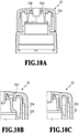
- Figs. 10A to 10C are explanatory views of the liquid storage container 2 of the embodiment.
- Fig. 10A is a cross-sectional view of the upper portion of the liquid storage container 2 in the state where the cap 23 is attached to the nozzle 22.
- the interior of the liquid storage container 2 is sealed by fitting the cap sealing portion 23b of the cap 23 to the nozzle sealing portion 22d of the nozzle 22.
- the cap sealing portion 23b has a rib shape, and the sealed state of the interior of the liquid storage container 2 is maintained by contact between the nozzle sealing portion 22d and the cap sealing portion 23b which is a rib.
- the rib forming the cap sealing portion 23b only needs to be in contact with the entire periphery of the nozzle sealing portion 22d and may have any shape.
- the shape of the rib is preferably a circular shape.
- the portion of the cap sealing portion 23b to be in contact with the nozzle sealing portion 22d may be on the inside, the outside, or a ceiling surface of the nozzle sealing portion 22d.
- the cap sealing portion 23b may be in contact with the nozzle sealing portion 22d at these multiple portions, simultaneously.
- Polypropylene (PP) or polyethylene (PE) is used as the materials of the cap 23 and the nozzle 22 in the embodiment.
- the same material or different materials may be used as a combination of the materials.
- two parts varying in physical property may be in contact with each other, or two parts made of the same material may be in contact with each other.
- different materials are preferably used.
- the cap 23 includes a rib 23c.
- the rib 23c is provided outside the sealing portion (first sealing portion) formed of the cap sealing portion 23b and the nozzle sealing portion 22d as illustrated in Fig. 10A .
- the rib 23c is provided to surround the entire periphery of the sealing portion in the cap 23.
- the distal end position of the rib 23c of the cap 23 is located lower than the fitting position between the cap sealing portion 23b of the cap 23 and the nozzle sealing portion 22d of the nozzle 22. Accordingly, the rib 23c serves as a wall against the droplets of liquid generated at the moment of opening the cap 23 and can suppress the droplets being guided to the outside of the cap.
- Fig. 10B is an enlarged view of Fig. 10A .
- the nozzle 22 includes a wall 22e protruding toward the cap 23.
- the wall 22e is provided outside the rib 23c of the cap 23 to surround the entire periphery of the rib 23c.
- the nozzle 22 is provided with a groove 22f at a lower end of the wall 22e. This configuration causes the droplets scattering beyond the rib 23c to collide with the wall 22e and accumulate in the groove 22f. Accordingly, it is possible to suppress scattering of the droplets to the outside of the liquid storage container 2.
- Fig. 10C is a view of another example of the cap 23.
- the rib 23c of the cap 23 may be in contact with the nozzle 22.
- the configuration in which the distal end of the rib 23c extends to be closer to the storage portion (bottle 21) than in Figs. 10A and 10B can increase the range in which the rib 23c receives the droplets.
- the distal end of the rib 23c in the cap 23 functions as the reference position of the cap 23 with respect to the nozzle 22.
- the liquid storage container 2 may include three or more sealing portions.
- the cap 23 may be an externally-fitted cover that fits on the outside of the nozzle 22 and an internally-fitted cover that fits on the inside of the nozzle 22.
- the liquid storage container 2 only needs to be configured such that the sealing portions are simultaneously unsealed in opening and closing the cap 23.
- the example based on the liquid storage container 2 described in the first embodiment is described.
- the liquid storage container 2 including the first sealing portion and the second sealing portion is described as an example.
- the liquid storage container 2 may be a liquid storage container including no second sealing portion.
- the liquid storage container may be a container used to replenish a liquid tank of any apparatus with liquid.
- the liquid storage container may store any kind of liquid.
Landscapes
- Closures For Containers (AREA)
Abstract
Description
- The present disclosure relates to a liquid storage container configured to store liquid.
- Among liquid tanks used in liquid ejecting apparatuses such as inkjet printing apparatuses, there is a liquid tank that can be replenished with liquid. For example, by using a liquid storage container including a discharge port for pouring the liquid, the liquid tank can be replenished with the liquid from the liquid storage container through the discharge port. In this type of liquid storage container, in order to prevent smearing of the surroundings and the hand of a user, a valve with a slit is provided at a front end of the discharge port, and leakage of the liquid is thereby forcedly stopped (see
Japanese Patent Laid-Open No. 2018-95277 -
Document 1 describes a container which includes a discharge port main body and a cover capable of opening and closing the discharge port by covering it and in which a valve with a slit is provided inside the discharge port main body.Document 1 describes a configuration in which the discharge port is sealed with the cover before the cover is completely closed, and then, completely closing the cover causes a protrusion formed in the cover to be inserted into the valve and open the slit portion of the valve. - In the configuration described in
Document 1, just after the cover starts to open, the protrusion moves away from the valve, and the valve is thereby closed. Thus, the sealing of the liquid storage container is maintained in the case where the cover is opened. With this configuration, in the case where the air pressure inside the liquid storage container is higher than the outside air pressure, there is a possibility that the liquid sprays out of the liquid storage container on opening the valve to replenish the liquid tank with the liquid from the liquid storage container. Moreover, there is a possibility that, in the case where the liquid storage container is tilted such that the discharge part is directed downward, the hydraulic head difference of the liquid in the liquid storage container acting on the valve exceeds the withstanding pressure of the valve and opens the valve, causing the liquid to spray out. The spraying-out liquid may directly reach the outside of the liquid storage container. - The present invention in its first aspect provides a liquid storage container as specified in
claims 1 to 15. - Further features of the present disclosure will become apparent from the following description of exemplary embodiments with reference to the attached drawings.
-
-
Fig. 1 is a perspective view of an outer appearance of a liquid ejecting apparatus; -
Fig. 2 is a perspective view of an internal configuration of the liquid ejecting apparatus; -
Figs. 3A and 3B are an enlarged perspective view and plan view of a portion of the liquid ejecting apparatus in which liquid tanks are housed; -
Fig. 4 is an outer appearance view of a liquid storage container; -
Figs. 5A and 5B are a part configuration view and cross-sectional view of the liquid storage container; -
Figs. 6A to 6C are explanatory views of sealing portions; -
Fig. 7 is a view of another sealing method for the sealing portions; -
Fig. 8 is a view of another sealing method for the sealing portions; -
Figs. 9A to 9C are views of various examples of protrusions configured to push a valve: and -
Figs. 10A to 10C are explanatory views of a liquid storage container. - Embodiments are described below with reference to the drawings. Note that the same configurations in the description are denoted by the same reference numerals. Moreover, the arrangement of constituent elements relative to one another, the shapes of the constituent elements, and the like that are described in the embodiments are merely examples.
-
Fig. 1 is a perspective view of an outer appearance of a liquid ejectingapparatus 1 in the embodiment. The liquid ejectingapparatus 1 illustrated inFig. 1 is a serial inkjet printing apparatus. The liquid ejectingapparatus 1 illustrated inFig. 1 includes acase 11 andliquid tanks 12 arranged inside thecase 11. Eachliquid tank 12 stores an ink that is liquid to be ejected to a print medium (not illustrated). -
Fig. 2 is a perspective view of an internal configuration of the liquid ejectingapparatus 1 illustrated inFig. 1 . InFig. 2 , the liquid ejectingapparatus 1 includes aconveyance roller 13 used to convey the print medium (not illustrated), acarriage 15 provided with aprint head 14 configured to eject the liquid, and acarriage motor 16 used to drive thecarriage 15. The print medium is not limited to a particular medium as long as an image can be formed on the medium with the liquid ejected from theprint head 14. For example, paper, cloth, the label surfaces of optical discs, plastic sheets, OHP sheets or the like can be given as print media. - The liquid is stored in the
liquid tanks 12 and is supplied to theprint head 14 via aliquid distribution passage 17 to be ejected from theprint head 14. In the embodiment, inks of four colors (for example, cyan, magenta, yellow, and black) are used as the liquid, and fourliquid tanks 12a to 12d for the respective colors that store the inks of the respective colors are provided as theliquid tanks 12. In the following description, in the case where the individual liquid tanks, distinguished from one another, are referred, alphabets are added at the ends, for example,liquid tanks 12a to 12d. In the case where any one of the liquid tanks is referred to, the liquid tank is referred to as theliquid tank 12. Theliquid tanks 12a to 12d for the respective colors are arranged in a front face portion of the liquid ejectingapparatus 1 inside thecase 11. -
Fig. 3A is an example of an enlarged perspective view of a portion of the liquid ejectingapparatus 1 illustrated inFig. 1 in which theliquid tanks 12b to 12d are housed, andFig. 3B is a plan view corresponding to the perspective view illustrated inFig. 3A . Eachliquid tank 12 includes a liquid tankmain body 121 used to store the liquid and acommunication flow passage 122 communicating with a liquid storage chamber in the liquid tankmain body 121. Theliquid tank 12 includes a tank cover 123 (seeFig. 2 ) configured to be attachable to cover thecommunication flow passage 122 and seal the storage chamber in the liquid tankmain body 121 in occasions other than an occasion of liquid replenishment. In the case where theliquid tank 12 is replenished with the liquid, a discharge port of a liquid storage container 2 (seeFig. 4 ) is inserted into thecommunication flow passage 122 and the liquid is poured into theliquid tank 12. The liquid storage chamber is sealed with thetank cover 123 in occasions other than the occasion of liquid replenishment, and thus it is possible to reduce evaporation of the liquid in theliquid tank 12. Thecommunication flow passage 122 includes two flow passages extending parallel to each other in the vertical direction in an interior thereof and is configured to allow the liquid in theliquid storage container 2 to be poured into the liquid tank by means of gas-liquid exchange. Asocket 18 is provided in a portion of the liquid ejectingapparatus 1 where the discharge port of theliquid storage container 2 is to be inserted. Thesocket 18 is provided with protrudingportions 19 protruding inward from an inner peripheral wall of thesocket 18. Thesocket 18 is provided for eachliquid tank 12, and the shapes of the protrudingportions 19 vary among thesockets 18 to suppress erroneous insertion of the liquid container. The protrudingportions 19 are rotationally symmetric by 180° with respect to the center axis of thecommunication flow passage 122. -
Fig. 4 is an elevation view of an outer appearance of theliquid storage container 2 which is a liquid container used to replenish theliquid tank 12 with the liquid. Theliquid storage container 2 inFig. 4 includes abottle 21 that is a storage portion (main body portion) configured to store the liquid, anozzle 22 coupled to thebottle 21, and acap 23 attachable to and detachable from thenozzle 22. Thenozzle 22 is a discharge port member having a function of an outlet for the case where the liquid stored in thebottle 21 is discharged. Thecap 23 is a cover portion that is attached to thenozzle 22 to shield the interior of the liquid storage container 2 (specifically, the bottle 21) from the outside air. Methods of coupling thebottle 21 and thenozzle 22 to each other include a method of sealing a space between thebottle 21 and thenozzle 22 by inserting a flexible part, a method of forming both of thebottle 21 and thenozzle 22 with resin parts and welding the two parts together, and the like. Thebottle 21 and thenozzle 22 may be an integral part. -
Fig. 5A illustrates an example of a part configuration view of theliquid storage container 2 illustrated inFig. 4 .Fig. 5B is a cross-sectional view in which the parts in the part configuration view of theliquid storage container 2 illustrated inFig. 5A are coupled to one another. Thebottle 21 of theliquid storage container 2 includes abottle welding portion 21a formed in an upper portion and aliquid storage portion 21b formed in a lower portion. Thenozzle 22 includes adischarge port 22a through which the liquid is discharged, anozzle thread portion 22b in which a male thread structure is formed on the outside, and anozzle welding portion 22c in which a welding surface is formed on the inside or a bottom surface. Thecap 23, which is the cover portion, is configured to be attachable to and detachable from thenozzle 22, which is the discharge port member, and can open and close thedischarge port 22a. Polyethylene (PE), polypropylene (PP), and the like can be given as examples of the material forming thebottle 21. Polyethylene (PE), polypropylene (PP), and the like can be given as the material forming thenozzle 22. Thenozzle 22 is joined to thebottle 21 by welding thenozzle welding portion 22c to thebottle welding portion 21a. In the case where thebottle 21 and thenozzle 22 are joined by being welded to each other, thebottle 21 and thenozzle 22 are preferably made of the same type of material. Aseal 24 having an opening, avalve 25 configured to open and close the opening of theseal 24, aspring 26 configured to bias thevalve 25, and aholder 27 configured to fix thespring 26 are included inside thenozzle 22. - In the case where the liquid is supplied from the
liquid storage container 2 to theliquid tank 12, thecommunication flow passage 122 of theliquid tank 12 is inserted into an opening of thenozzle 22 of theliquid storage container 2. Thenozzle 22 of theliquid storage container 2 is provided with recess portions configured to engage with the protrudingportions 19 of thesocket 18 in theliquid ejecting apparatus 1, and theliquid storage container 2 is aligned in the case where thecommunication flow passage 122 is inserted into the opening of thenozzle 22. Then, the liquid in theliquid storage container 2 is supplied to the storage chamber of the liquid tankmain body 121 via thecommunication flow passage 122 by means of hydraulic head difference. - The
liquid storage container 2 includes two sealable portions (hereinafter, referred to as sealing portions).Figs. 6A to 6C are explanatory views of the sealing portions. As illustrated inFig. 6A , in a first sealing portion, sealing is achieved by fitting thecap 23 to thenozzle 22. As illustrated inFig. 6B , in a second sealing portion, sealing is achieved by a valve structure in thenozzle 22. The sealing portions are described below. - The first sealing portion is described with reference to
Fig. 6A. Fig. 6A is a cross-sectional view of an upper portion of theliquid storage container 2 in a state where thecap 23 is attached to thenozzle 22, and also illustrates an enlarged view of the upper portion. The first sealing portion is a portion in which acap sealing portion 23b of thecap 23 is fitted to anozzle sealing portion 22d that is part of thedischarge port 22a of thenozzle 22 by attaching thecap 23 to thenozzle 22. As an example of a method of attaching thecap 23 to thenozzle 22, there is a method of screwing thecap 23 to thenozzle 22. Specifically, as illustrated inFigs. 5A, 5B , and6A , there is a method of screwing thecap 23 to thenozzle 22 by using thenozzle thread portion 22b in which the male thread structure is formed on the outside of thenozzle 22 and acap thread portion 23a in which a female thread structure is formed on the inside of a lower portion of thecap 23. Conversely, the attachment may be achieved by using acap 23 in which a male thread portion is formed and anozzle 22 in which a female thread portion is formed. - Moreover, as the method of attaching the
cap 23 to thenozzle 22, instead of screwing, a fitting portion other than the sealing portion may be provided. For example, there may be employed a configuration such as an externally-fitted cover in which acap 23 is fitted to the outside of anozzle 22 or an internally-fitted cover in which acap 23 is fitted to the inside of anozzle 22. - The second sealing portion is described with reference to
Fig. 6B. Fig. 6B is a cross-sectional view of the upper portion of theliquid storage container 2 in a state where nocap 23 is attached, and also illustrates an enlarged view of the upper portion. The second sealing portion is a portion of a liquid stop valve structure (valve structure) arranged inside thenozzle 22 of theliquid storage container 2. As illustrated inFig. 6B , theseal 24 which is an orifice portion having an opening into which thecommunication flow passage 122 is to be inserted is arranged in a front end (upper end) of thenozzle 22. Then, thevalve 25, which is a valve element of the liquid stop valve, is biased toward the opening with thespring 26, thereby the gap between theseal 24 and thevalve 25 is closed, and theliquid storage container 2 is sealed. In the embodiment, thespring 26 is used as a biasing mechanism, and theholder 27 fixed in an inner space of thenozzle 22 holds thespring 26. Theseal 24 is formed of a flexible member made of rubber, elastomer, or the like. - Since the
valve 25 is biased toward the opening of theseal 24 with thespring 26, the liquid stop valve structure can maintain the interior of theliquid storage container 2 in the sealed state in the state where thecap 23 is removed from thenozzle 22. In the case where the liquid is supplied from theliquid storage container 2 to theliquid tank 12, thecommunication flow passage 122 is inserted into thenozzle 22 through the opening of theseal 24, thereby opening thevalve 25. Then, as described above, the liquid in theliquid storage container 2 is supplied to the storage chamber of the liquid tankmain body 121 via thecommunication flow passage 122 by means of hydraulic head difference. - In the embodiment, the two sealing portions are configured to be temporarily simultaneously unsealed in cap-opening in which the
cap 23 is removed fromnozzle 22 and in cap-closing in which the cap is attached to thenozzle 22. This configuration allows the interior of theliquid storage container 2 to communicate with the atmosphere and can equalize the pressure inside theliquid storage container 2 with the outside air pressure. Details are described below. - As illustrated in
Fig. 6A , in the state where thecap 23 is closed, the first sealing portion is in a sealed state. Meanwhile, in the second sealing portion, aprotrusion 23f arranged in thecap 23 is pushed in a direction opposite to the biasing direction of thevalve 25 with the closing of thecap 23, and a gap is thereby formed between theseal 24 and thevalve 25. As described above, inFig. 6A , the second sealing portion is in an unsealed state. Specifically, in the closed state of thecap 23, the first sealing portion is sealed, and the second sealing portion is unsealed. -
Fig. 6C is a cross-sectional view of an upper portion of theliquid storage container 2 in a state where thecap 23 has started to be opened from the state where thecap 23 is attached to thenozzle 22 illustrated inFig. 6A , and also illustrates an enlarged view of the upper portion. Thecap 23 moves upward from the closed state illustrated inFig. 6A along with the cap-opening as illustrated inFig. 6C . Thecap sealing portion 23b and thenozzle sealing portion 22d separate from each other along with this movement of thecap 23, and the first sealing portion is unsealed. In the unsealing of the first sealing portion, theprotrusion 23f arranged in thecap 23 is still at such a position that theprotrusion 23f pushes thevalve 25 as illustrated inFig. 6C . Specifically, the unsealed state of the second sealing portion is maintained. Accordingly, as illustrated inFig. 6C , the second sealing portion and the first sealing portion can be simultaneously unsealed in unsealing the first sealing portion. Then, in the case where thecap 23 is further moved upward, theprotrusion 23f completely separates from thevalve 25 along with the movement of thecap 23, and as illustrated inFig. 6B , the second sealing portion is sealed. Note that, also in the case where thecap 23 is closed from the open state, theprotrusion 23f of thecap 23 pushes thevalve 25 along with the movement of thecap 23, and the second sealing portion is unsealed. In this case, since the first sealing portion is in a pre-sealed state, the unsealed state of the first sealing portion is maintained. Then, setting thecap 23 to the closed state sets the first sealing portion to the sealed state. Note that the first sealing portion and the second sealing portion are simultaneously unsealed means that the first sealing portion and the second sealing portion are substantially simultaneously unsealed. In the case where unsealing of the first sealing portion causes the second sealing portion to be unsealed in conjunction, it means that both sealing portions are simultaneously unsealed. - Since the above configuration temporarily simultaneously sets the first sealing portion and the second sealing portion to the unsealed state in opening the
cap 23, this configuration allows the interior of theliquid storage container 2 to communicate with the atmosphere and can equalize the pressure in theliquid storage container 2 with the outside air pressure. Accordingly, the occurrence of spraying-out of the liquid due to an increase in the internal pressure of theliquid storage container 2 can be suppressed in the case where thecap 23 is opened and the liquid tankmain body 121 is replenished with the liquid from theliquid storage container 2. Moreover, it is possible to suppress the occurrence of overflow of the liquid from the liquid tankmain body 121. Furthermore, since the second sealing portion maintains the interior of theliquid storage container 2 in the sealed state after thecap 23 is opened, the occurrence of leakage of the liquid can be suppressed even if theliquid storage container 2 is turned upside down. - As a sealing method of the two sealing portions described above, there are a method of achieving sealing by pressing a rigid material and a flexible material such as rubber or elastomer against each other, a method of achieving sealing by fitting rigid materials to each other, and the like.
- In the embodiment, there is employed a method in which a rigid material such as polyethylene (PE) or polypropylene (PP) is used for the
nozzle 22 and thecap 23 in the first sealing portion, and these parts are configured to be fitted to each other. In the first sealing portion, two parts made of the same material may be fitted to be in contact with each other, or two parts varying in physical property may be brought into contact with each other. A flexible material such as rubber or elastomer is used as the material forming theseal 24 in the second sealing portion. A rigid material such as polyethylene (PE) or polypropylene (PP) is used as the material forming thevalve 25 in the second sealing portion. Then, there is employed a method of achieving sealing by pressing theseal 24 and thevalve 25 against each other. -
Fig. 7 is a view of another sealing method for the first sealing portion. As illustrated inFig. 7 , the first sealing portion may employ a method in which aflexible material 23e is used in one of thenozzle 22 or thecap 23, and sealing is achieved by pressing theflexible material 23e against the other part.Fig. 8 is a view of another sealing method for the second sealing portion. As illustrated inFig. 8 , the second sealing portion may employ a method in which aflexible material 24c is used in thevalve 25 and sealing is achieved by pressing the material 24c against thenozzle 22 for which a rigid material is used. -
Figs. 9A to 9C are views of various types ofprotrusions 23f configured to push thevalve 25. The shape of theprotrusion 23f arranged in thecap 23 and configured to push thevalve 25 is preferably such a shape that the distal end of the protrusion forms a surface extending in directions perpendicular to the moving direction of thevalve 25 and can push thevalve 25 without causing thevalve 25 to tilt. For example, theprotrusion 23f may have a cylindrical shape such as a columnar shape or a conical shape as illustrated inFig. 9A or a polygonal shape such as a polygonal prism shape or a polygonal pyramid shape as illustrated inFig. 9B . - Moreover, as illustrated in
Fig. 9C , aflexible material 23g may be used in the distal end of theprotrusion 23f. Using theflexible material 23g can suppress deformation of thevalve 25 in the case where theprotrusion 23f comes into contact with thevalve 25. - Stainless steel (SUS) and the like can be given as the material forming the
spring 26. Polyethylene (PE), polypropylene (PP), and the like can be given as the material forming theholder 27. As a method of fixing theholder 27 to thenozzle 22, it is preferable to form theholder 27 and thenozzle 22 by using the same material and welding theholder 27 and thenozzle 22 to each other. - As described above, in the embodiment, in opening and closing the
cap 23, the state where thevalve 25 is opened by theprotrusion 23f of thecap 23 occurs while thecap 23 and thenozzle 22 are not sealed. Specifically, the state where the first sealing portion and the second sealing portion are temporarily simultaneously unsealed occurs. Accordingly, it is possible to cause the interior of theliquid storage container 2 to communicate with the atmosphere and equalize the pressure in theliquid storage container 2 with the outside air pressure. This can suppress the occurrence of overflow in theliquid tank 12 due to spraying-out of the liquid in the case where theliquid tank 12 is replenished with the liquid from theliquid storage container 2. Moreover, it is possible to suppress the occurrence of spraying-out of the liquid that would occur in the case where theliquid storage container 2 is tilted. - In the first embodiment, a description is given of the example in which the pressure in the
liquid storage container 2 is released by employing the configuration in which the two sealing portions are temporarily simultaneously unsealed in opening and closing thecap 23. Simultaneously unsealing the two sealing portions can suppress the occurrence of spraying-out of the liquid in theliquid storage container 2. However, simultaneously unsealing the two sealing portions may sometimes cause droplets of the liquid in theliquid storage container 2 to come out. In the present embodiment, a description is given of an example of suppressing the occurrence of the case where the liquid in theliquid storage container 2 turns into droplets and scatters to the outside of the container. The basic configuration of theliquid storage container 2 is the same as that in the first embodiment, and description thereof is omitted. -
Figs. 10A to 10C are explanatory views of theliquid storage container 2 of the embodiment.Fig. 10A is a cross-sectional view of the upper portion of theliquid storage container 2 in the state where thecap 23 is attached to thenozzle 22. As described in the first embodiment, the interior of theliquid storage container 2 is sealed by fitting thecap sealing portion 23b of thecap 23 to thenozzle sealing portion 22d of thenozzle 22. Thecap sealing portion 23b has a rib shape, and the sealed state of the interior of theliquid storage container 2 is maintained by contact between thenozzle sealing portion 22d and thecap sealing portion 23b which is a rib. The rib forming thecap sealing portion 23b only needs to be in contact with the entire periphery of thenozzle sealing portion 22d and may have any shape. In the case where a thread shape is employed as a method of attaching thecap 23 to thenozzle 22, the shape of the rib is preferably a circular shape. Note that the portion of thecap sealing portion 23b to be in contact with thenozzle sealing portion 22d may be on the inside, the outside, or a ceiling surface of thenozzle sealing portion 22d. Thecap sealing portion 23b may be in contact with thenozzle sealing portion 22d at these multiple portions, simultaneously. - Polypropylene (PP) or polyethylene (PE) is used as the materials of the
cap 23 and thenozzle 22 in the embodiment. The same material or different materials may be used as a combination of the materials. Specifically, in the contact portion, two parts varying in physical property may be in contact with each other, or two parts made of the same material may be in contact with each other. In the case where thecap 23 and thenozzle 22 are assembled together at high speed, different materials are preferably used. - In the case where the sealed state is canceled with the outside air pressure being lower than the pressure inside the sealed space of the
liquid storage container 2, gas and liquid contained in the interior of theliquid storage container 2 are guided to the outside. In the embodiment, as illustrated inFig. 10A , thecap 23 includes arib 23c. In the plan view of thecap 23, therib 23c is provided outside the sealing portion (first sealing portion) formed of thecap sealing portion 23b and thenozzle sealing portion 22d as illustrated inFig. 10A . Therib 23c is provided to surround the entire periphery of the sealing portion in thecap 23. In the embodiment, in opening thecap 23, the distal end position of therib 23c of thecap 23 is located lower than the fitting position between thecap sealing portion 23b of thecap 23 and thenozzle sealing portion 22d of thenozzle 22. Accordingly, therib 23c serves as a wall against the droplets of liquid generated at the moment of opening thecap 23 and can suppress the droplets being guided to the outside of the cap. -
Fig. 10B is an enlarged view ofFig. 10A . Thenozzle 22 includes awall 22e protruding toward thecap 23. Thewall 22e is provided outside therib 23c of thecap 23 to surround the entire periphery of therib 23c. Moreover, thenozzle 22 is provided with agroove 22f at a lower end of thewall 22e. This configuration causes the droplets scattering beyond therib 23c to collide with thewall 22e and accumulate in thegroove 22f. Accordingly, it is possible to suppress scattering of the droplets to the outside of theliquid storage container 2. -
Fig. 10C is a view of another example of thecap 23. As illustrated inFig. 10C , therib 23c of thecap 23 may be in contact with thenozzle 22. The configuration in which the distal end of therib 23c extends to be closer to the storage portion (bottle 21) than inFigs. 10A and 10B can increase the range in which therib 23c receives the droplets. Moreover, the distal end of therib 23c in thecap 23 functions as the reference position of thecap 23 with respect to thenozzle 22. - As described above, according to the embodiment, it is possible to suppress scattering of the droplets of the liquid in the
liquid storage container 2 to the outside in opening thecap 23 to remove it from thenozzle 22. - Although the example in which the
liquid storage container 2 includes two sealing portions of the first sealing portion and the second sealing portion is described in the first embodiment, theliquid storage container 2 may include three or more sealing portions. For example, thecap 23 may be an externally-fitted cover that fits on the outside of thenozzle 22 and an internally-fitted cover that fits on the inside of thenozzle 22. In any case, theliquid storage container 2 only needs to be configured such that the sealing portions are simultaneously unsealed in opening and closing thecap 23. - In the second embodiment, the example based on the
liquid storage container 2 described in the first embodiment is described. Specifically, theliquid storage container 2 including the first sealing portion and the second sealing portion is described as an example. However, theliquid storage container 2 may be a liquid storage container including no second sealing portion. - Although the example in which the liquid storage container is used to replenish the liquid tank of the liquid ejecting apparatus with the liquid is described in the above embodiments, the liquid storage container may be a container used to replenish a liquid tank of any apparatus with liquid. Moreover, although the example in which the ink is used as the liquid stored in the liquid storage container is described, the liquid storage container may store any kind of liquid.
- While the present disclosure has been described with reference to exemplary embodiments, it is to be understood that the disclosure is not limited to the disclosed exemplary embodiments. The scope of the following claims is to be accorded the broadest interpretation so as to encompass all such modifications and equivalent structures and functions.
Claims (15)
- A liquid storage container (2) comprising:a discharge port member (22) including a discharge port (22a) through which liquid stored in a storage portion (21) is discharged;a cover portion (23) configured to be attachable to and detachable from the discharge port member (22) and to be capable of opening and closing the discharge port (22a);a liquid stop valve (25) provided inside the discharge port member (22); anda protrusion (23f) provided inside the cover portion (23) and configured to open the liquid stop valve (25) in closing the cover portion (23), whereinthe storage portion (21) is sealable by at least one of a first sealing portion formed of a contact portion between the cover portion (23) and the discharge port member (22) and a second sealing portion formed of the liquid stop valve (25), andthe first sealing portion and the second sealing portion are configured to be simultaneously unsealed.
- The liquid storage container according to claim 1, wherein unsealing of the liquid stop valve by the protrusion and unsealing by separation of the cover portion and the discharge port member simultaneously occur in opening the cover portion.
- The liquid storage container according to claim 1 or 2, wherein further opening the cover portion from a state where the first sealing portion and the second sealing portion are simultaneously unsealed causes the second sealing portion to be sealed.
- The liquid storage container according to any one of claims 1 to 3, whereinthe liquid stop valve includes an orifice portion, a valve element, and a biasing mechanism configured to bias the valve element, andthe biasing mechanism closes a gap between the orifice portion and the valve element.
- The liquid storage container according to claim 4, wherein the orifice portion is formed of a flexible member.
- The liquid storage container according to claim 4 or 5, wherein the gap is formed by the protrusion pushing the valve element.
- The liquid storage container according to any one of claims 1 to 6, whereinthe cover portion and the discharge port member include thread structures, respectively, andthe cover portion is attached to the discharge port member by the thread structures.
- The liquid storage container according to any one of claims 1 to 7, wherein the protrusion has a cylindrical shape.
- The liquid storage container according to any one of claims 1 to 7, wherein the protrusion has a polygonal shape.
- The liquid storage container according to any one of claims 1 to 9, wherein two parts varying in physical property are configured to be in contact with each other in at least one of the first sealing portion and the second sealing portion.
- The liquid storage container according to any one of claims 1 to 9, wherein two parts made of the same material are configured to be in contact with each other in at least one of the first sealing portion and the second sealing portion.
- The liquid storage container according to any one of claims 1 to 11, wherein a rib located outside the first sealing portion is included inside the cover portion.
- The liquid storage container according to claim 12, wherein the rib is formed to surround an entire periphery of the sealing portion inside the cover portion.
- The liquid storage container according to claim 12 or 13, wherein a distal end of the rib is located on the storage portion side of the discharge port.
- The liquid storage container according to any one of claims 12 to 14, wherein the discharge port member includes a wall configured to surround the rib of the cover portion.
Applications Claiming Priority (1)
| Application Number | Priority Date | Filing Date | Title |
|---|---|---|---|
| JP2020122025A JP7577473B2 (en) | 2020-07-16 | 2020-07-16 | Ink storage container |
Publications (2)
| Publication Number | Publication Date |
|---|---|
| EP3939794A1 true EP3939794A1 (en) | 2022-01-19 |
| EP3939794B1 EP3939794B1 (en) | 2024-04-24 |
Family
ID=76890908
Family Applications (1)
| Application Number | Title | Priority Date | Filing Date |
|---|---|---|---|
| EP21185107.6A Active EP3939794B1 (en) | 2020-07-16 | 2021-07-12 | Liquid storage container |
Country Status (4)
| Country | Link |
|---|---|
| US (1) | US11584132B2 (en) |
| EP (1) | EP3939794B1 (en) |
| JP (1) | JP7577473B2 (en) |
| CN (2) | CN116330851A (en) |
Cited By (1)
| Publication number | Priority date | Publication date | Assignee | Title |
|---|---|---|---|---|
| CN117465141A (en) * | 2023-12-11 | 2024-01-30 | 中山易择优资打印科技有限公司 | Ink bottle and manufacturing method thereof |
Families Citing this family (16)
| Publication number | Priority date | Publication date | Assignee | Title |
|---|---|---|---|---|
| JPWO2018021210A1 (en) * | 2016-07-27 | 2019-04-04 | 中国塗料株式会社 | 3D surface roughness evaluation apparatus, 3D surface roughness evaluation method, 3D surface roughness data acquisition apparatus, and 3D surface roughness data acquisition method |
| JP7500313B2 (en) | 2020-07-16 | 2024-06-17 | キヤノン株式会社 | Ink storage container |
| JP2022018869A (en) | 2020-07-16 | 2022-01-27 | キヤノン株式会社 | Liquid storage container |
| JP7564660B2 (en) | 2020-07-31 | 2024-10-09 | キヤノン株式会社 | Recording device |
| JP7707772B2 (en) | 2021-08-31 | 2025-07-15 | ブラザー工業株式会社 | liquid supply device |
| JP7700591B2 (en) | 2021-08-31 | 2025-07-01 | ブラザー工業株式会社 | Liquid containing bottle |
| JP7707771B2 (en) | 2021-08-31 | 2025-07-15 | ブラザー工業株式会社 | Liquid containing bottle |
| JP7700590B2 (en) * | 2021-08-31 | 2025-07-01 | ブラザー工業株式会社 | Liquid containing bottle |
| JP7690820B2 (en) | 2021-08-31 | 2025-06-11 | ブラザー工業株式会社 | Liquid containing bottle |
| JP2023146057A (en) * | 2022-03-29 | 2023-10-12 | セイコーエプソン株式会社 | ink supply container |
| US12319065B2 (en) | 2022-03-29 | 2025-06-03 | Seiko Epson Corporation | Ink refill container |
| US12420554B2 (en) | 2022-06-08 | 2025-09-23 | Canon Kabushiki Kaisha | Printing apparatus and liquid container |
| JP2024088522A (en) | 2022-12-20 | 2024-07-02 | キヤノン株式会社 | LIQUID EJECTION DEVICE AND HEAD UNIT |
| JP2024126828A (en) | 2023-03-08 | 2024-09-20 | キヤノン株式会社 | Liquid storage container |
| CN121816272A (en) * | 2023-09-11 | 2026-04-07 | 兄弟工业株式会社 | liquid bottle |
| JP2025068740A (en) | 2023-10-17 | 2025-04-30 | セイコーエプソン株式会社 | Ink storage container |
Citations (7)
| Publication number | Priority date | Publication date | Assignee | Title |
|---|---|---|---|---|
| US20170355194A1 (en) * | 2016-06-10 | 2017-12-14 | Seiko Epson Corporation | Ink replenish container |
| US20180250943A1 (en) * | 2017-03-01 | 2018-09-06 | Seiko Epson Corporation | Printer and ink bottle |
| US20190030903A1 (en) * | 2017-07-31 | 2019-01-31 | Seiko Epson Corporation | Ink refill container |
| US20190381799A1 (en) * | 2018-06-14 | 2019-12-19 | Kyocera Document Solutions Inc. | Cap, ink container and image forming apparatus |
| WO2020017617A1 (en) * | 2018-07-18 | 2020-01-23 | 株式会社ダイゾー | Double pressurized container, discharge product, discharge member, dispenser system and manufacturing method for discharge product |
| JP2020019570A (en) * | 2018-07-18 | 2020-02-06 | 株式会社ダイゾー | Double pressurized container, discharge product, discharge member, discharge device, and dispenser system using them |
| EP3628497A1 (en) * | 2018-09-28 | 2020-04-01 | Canon Kabushiki Kaisha | Ink cartridge |
Family Cites Families (62)
| Publication number | Priority date | Publication date | Assignee | Title |
|---|---|---|---|---|
| US5732751A (en) * | 1995-12-04 | 1998-03-31 | Hewlett-Packard Company | Filling ink supply containers |
| ATE251039T1 (en) | 1996-11-15 | 2003-10-15 | Canon Kk | CONTAINER FOR DISPENSING LIQUID |
| JP3295366B2 (en) | 1997-02-19 | 2002-06-24 | キヤノン株式会社 | Liquid holding container with cap, cap and liquid holding container |
| JP3286210B2 (en) | 1997-06-19 | 2002-05-27 | キヤノン株式会社 | Ink tank |
| EP1264695A1 (en) | 1999-04-05 | 2002-12-11 | Canon Kabushiki Kaisha | Ink absorbent, ink tank, ink jet cartridge, method for manufacturing ink absorbent, and method for manufacturing ink tank |
| JP3706782B2 (en) | 1999-04-15 | 2005-10-19 | キヤノン株式会社 | Method for producing fiber laminate, fiber laminate produced by the method, liquid storage container containing the fiber laminate, and liquid discharge head cartridge having the container |
| JP3745161B2 (en) | 1999-04-15 | 2006-02-15 | キヤノン株式会社 | Liquid storage container |
| JP2001063090A (en) * | 1999-04-27 | 2001-03-13 | Canon Inc | Ink tank, valve unit used for the ink tank, method for manufacturing the ink tank, inkjet head cartridge including the ink tank, and inkjet recording apparatus |
| JP2001063079A (en) | 1999-08-24 | 2001-03-13 | Canon Inc | Liquid storage container, liquid discharge mechanism and liquid discharge device |
| JP3647326B2 (en) | 1999-08-24 | 2005-05-11 | キヤノン株式会社 | Liquid storage container, liquid discharge mechanism, and ink jet recording apparatus |
| JP3809401B2 (en) | 2001-07-27 | 2006-08-16 | キヤノン株式会社 | Ink tank |
| JP4585797B2 (en) | 2004-06-07 | 2010-11-24 | キヤノン株式会社 | Liquid supply device |
| JP3977355B2 (en) | 2004-06-07 | 2007-09-19 | キヤノン株式会社 | Ink tank and recording head |
| JP4522245B2 (en) | 2004-12-09 | 2010-08-11 | キヤノン株式会社 | Liquid container and inkjet recording apparatus |
| JP4560401B2 (en) | 2004-12-22 | 2010-10-13 | キヤノン株式会社 | Ink tank and ink jet recording apparatus |
| US7503469B2 (en) * | 2005-03-09 | 2009-03-17 | Rexam Closure Systems Inc. | Integrally molded dispensing valve and method of manufacture |
| JP4994648B2 (en) | 2005-11-30 | 2012-08-08 | キヤノン株式会社 | Ink tank and ink jet recording apparatus using the same |
| JP2007152733A (en) | 2005-12-05 | 2007-06-21 | Canon Inc | Ink jet recording apparatus and ink tank for the apparatus |
| US8313185B2 (en) | 2006-03-31 | 2012-11-20 | Canon Kabushiki Kaisha | Liquid container and liquid container package |
| CN2910576Y (en) | 2006-04-28 | 2007-06-13 | 珠海天威技术开发有限公司 | Ink cartridge of ink-jet printer and its one-way valve |
| JP4926538B2 (en) | 2006-05-11 | 2012-05-09 | キヤノン株式会社 | Liquid storage container and recording apparatus |
| JP4164519B2 (en) | 2006-06-16 | 2008-10-15 | キヤノン株式会社 | Inkjet recording device |
| JP4942163B2 (en) | 2006-08-03 | 2012-05-30 | キヤノン株式会社 | Ink storage container |
| US7950790B2 (en) | 2006-09-11 | 2011-05-31 | Canon Kabushiki Kaisha | Ink container and ink jet recording apparatus |
| JP5224754B2 (en) | 2006-11-29 | 2013-07-03 | キヤノン株式会社 | Inkjet recording device |
| JP5031506B2 (en) | 2007-10-12 | 2012-09-19 | キヤノン株式会社 | Ink tank and recording device |
| ATE499215T1 (en) | 2008-03-31 | 2011-03-15 | Canon Kk | INK TANK AND INKJET RECORDING SYSTEM |
| JP5135125B2 (en) * | 2008-08-28 | 2013-01-30 | 株式会社吉野工業所 | Application container |
| JP5550220B2 (en) | 2008-08-29 | 2014-07-16 | キヤノン株式会社 | Ink tank |
| EP2783862B1 (en) | 2013-03-28 | 2019-05-08 | Brother Kogyo Kabushiki Kaisha | Liquid cartridge |
| JP6016707B2 (en) | 2013-04-26 | 2016-10-26 | 京セラドキュメントソリューションズ株式会社 | Liquid container and inkjet image forming apparatus provided with the same |
| JP5960345B2 (en) | 2013-09-18 | 2016-08-02 | キヤノン株式会社 | Ink cartridge and inkjet printer |
| CN105722684B (en) | 2013-09-18 | 2017-12-05 | 佳能株式会社 | Ink Cartridges and Inkjet Printers |
| JP6415114B2 (en) | 2014-05-30 | 2018-10-31 | キヤノン株式会社 | Liquid storage unit, liquid discharge apparatus using the same, and method for removing bubbles from liquid storage unit |
| US9375938B2 (en) | 2014-06-27 | 2016-06-28 | Canon Kabushiki Kaisha | Ink cartridge and ink jet printing apparatus |
| JP6395471B2 (en) | 2014-06-27 | 2018-09-26 | キヤノン株式会社 | Liquid storage container and liquid discharge device |
| CN107107621B (en) | 2015-04-21 | 2019-04-02 | 惠普发展公司,有限责任合伙企业 | Ink tank |
| US9895900B2 (en) * | 2015-07-21 | 2018-02-20 | Brother Kogyo Kabushiki Kaisha | Liquid cartridge having structure for opening and closing liquid channel and air channel |
| EP3359382B1 (en) | 2015-10-08 | 2020-06-17 | Sicpa Holding Sa | Secure refill system |
| JP6611564B2 (en) | 2015-10-30 | 2019-11-27 | キヤノン株式会社 | Liquid storage bottle and liquid storage bottle package |
| JP6498098B2 (en) | 2015-10-30 | 2019-04-10 | キヤノン株式会社 | Recording apparatus and liquid storage member |
| JP6775132B2 (en) * | 2016-03-16 | 2020-10-28 | キョーラク株式会社 | Double container |
| US9914308B2 (en) | 2016-01-08 | 2018-03-13 | Canon Kabushiki Kaisha | Liquid ejection apparatus and liquid ejection head |
| US10005287B2 (en) | 2016-01-08 | 2018-06-26 | Canon Kabushiki Kaisha | Liquid ejection apparatus, liquid ejection head, and method of supplying liquid |
| JP6611618B2 (en) | 2016-01-08 | 2019-11-27 | キヤノン株式会社 | Recording apparatus, recording apparatus control method, and program |
| JP6716258B2 (en) | 2016-01-08 | 2020-07-01 | キヤノン株式会社 | Recording device, recording device control method, and program |
| JP6808324B2 (en) | 2016-01-08 | 2021-01-06 | キヤノン株式会社 | Liquid discharge recorder and liquid discharge head |
| JP2017209864A (en) | 2016-05-25 | 2017-11-30 | キヤノン株式会社 | Liquid discharge device and liquid discharge head |
| US10350901B2 (en) | 2016-06-10 | 2019-07-16 | Seiko Epson Corporation | Ink bottle |
| US10308029B2 (en) | 2016-06-10 | 2019-06-04 | Seiko Epson Corporation | Liquid holding unit and liquid ejection device |
| JP6915304B2 (en) | 2017-03-01 | 2021-08-04 | セイコーエプソン株式会社 | Ink replenishment container |
| JP6759876B2 (en) * | 2016-09-02 | 2020-09-23 | セイコーエプソン株式会社 | Bottle set, bottle |
| JP6903905B2 (en) | 2016-12-12 | 2021-07-14 | 凸版印刷株式会社 | Liquid dripping prevention cap and its manufacturing method |
| IT201700061470A1 (en) | 2017-06-06 | 2018-12-06 | Emanuela Covi | CLOSING DEVICE, VALVE GROUP AND CONTAINER |
| JP7267708B2 (en) | 2017-10-13 | 2023-05-02 | キヤノン株式会社 | MEMBER HAVING PAD ELECTRODE, INK CARTRIDGE, RECORDING DEVICE |
| JP2019093669A (en) | 2017-11-27 | 2019-06-20 | キヤノン株式会社 | Liquid supplement container and liquid supplement system |
| JP6995446B2 (en) * | 2017-12-27 | 2022-01-14 | 株式会社吉野工業所 | cap |
| JP7307528B2 (en) * | 2018-01-30 | 2023-07-12 | 株式会社吉野工業所 | hinge cap |
| US11603257B2 (en) | 2018-07-18 | 2023-03-14 | Daizo Corporation | Double pressurized container, discharge product, discharge member, dispenser system and manufacturing method for discharge product |
| JP2020033090A (en) * | 2018-08-31 | 2020-03-05 | 株式会社吉野工業所 | Hinge cap |
| JP7110038B2 (en) | 2018-09-06 | 2022-08-01 | キヤノン株式会社 | Liquid storage container and liquid ejection device |
| JP7257856B2 (en) | 2019-04-05 | 2023-04-14 | キヤノン株式会社 | recording device |
-
2020
- 2020-07-16 JP JP2020122025A patent/JP7577473B2/en active Active
-
2021
- 2021-07-08 US US17/370,948 patent/US11584132B2/en active Active
- 2021-07-12 EP EP21185107.6A patent/EP3939794B1/en active Active
- 2021-07-13 CN CN202310537704.1A patent/CN116330851A/en active Pending
- 2021-07-13 CN CN202110787384.6A patent/CN113942311B/en active Active
Patent Citations (7)
| Publication number | Priority date | Publication date | Assignee | Title |
|---|---|---|---|---|
| US20170355194A1 (en) * | 2016-06-10 | 2017-12-14 | Seiko Epson Corporation | Ink replenish container |
| US20180250943A1 (en) * | 2017-03-01 | 2018-09-06 | Seiko Epson Corporation | Printer and ink bottle |
| US20190030903A1 (en) * | 2017-07-31 | 2019-01-31 | Seiko Epson Corporation | Ink refill container |
| US20190381799A1 (en) * | 2018-06-14 | 2019-12-19 | Kyocera Document Solutions Inc. | Cap, ink container and image forming apparatus |
| WO2020017617A1 (en) * | 2018-07-18 | 2020-01-23 | 株式会社ダイゾー | Double pressurized container, discharge product, discharge member, dispenser system and manufacturing method for discharge product |
| JP2020019570A (en) * | 2018-07-18 | 2020-02-06 | 株式会社ダイゾー | Double pressurized container, discharge product, discharge member, discharge device, and dispenser system using them |
| EP3628497A1 (en) * | 2018-09-28 | 2020-04-01 | Canon Kabushiki Kaisha | Ink cartridge |
Cited By (1)
| Publication number | Priority date | Publication date | Assignee | Title |
|---|---|---|---|---|
| CN117465141A (en) * | 2023-12-11 | 2024-01-30 | 中山易择优资打印科技有限公司 | Ink bottle and manufacturing method thereof |
Also Published As
| Publication number | Publication date |
|---|---|
| CN113942311A (en) | 2022-01-18 |
| US20220016893A1 (en) | 2022-01-20 |
| US11584132B2 (en) | 2023-02-21 |
| CN116330851A (en) | 2023-06-27 |
| JP2022018712A (en) | 2022-01-27 |
| EP3939794B1 (en) | 2024-04-24 |
| JP7577473B2 (en) | 2024-11-05 |
| CN113942311B (en) | 2023-05-23 |
Similar Documents
| Publication | Publication Date | Title |
|---|---|---|
| EP3939794B1 (en) | Liquid storage container | |
| EP3939795B1 (en) | Liquid storage container | |
| KR102945764B1 (en) | Liquid storage container | |
| US20220055369A1 (en) | Ink bottle and bottle set | |
| RU2719697C2 (en) | Paint replenishment container, paint replenishment system and paint replenishment adapter | |
| CN111746904B (en) | Liquid storage bottle | |
| WO2022264875A1 (en) | Liquid supplying device and liquid supplying system | |
| JP2018140556A (en) | Ink supply container and ink supply system | |
| US7597433B2 (en) | Ink cartridge, inkjet printer and combination thereof | |
| JP2017140794A (en) | Liquid storage body and liquid jet device | |
| CN114475002A (en) | Ink replenishing container | |
| CN111746903A (en) | Liquid storage bottle | |
| CN119017843A (en) | Liquid containers and liquid refill systems | |
| CN121605042A (en) | Ink containers, ink container sets, and printing systems | |
| CN116061568A (en) | Ink replenishing container | |
| JP2014061675A (en) | cartridge |
Legal Events
| Date | Code | Title | Description |
|---|---|---|---|
| PUAI | Public reference made under article 153(3) epc to a published international application that has entered the european phase |
Free format text: ORIGINAL CODE: 0009012 |
|
| STAA | Information on the status of an ep patent application or granted ep patent |
Free format text: STATUS: THE APPLICATION HAS BEEN PUBLISHED |
|
| AK | Designated contracting states |
Kind code of ref document: A1 Designated state(s): AL AT BE BG CH CY CZ DE DK EE ES FI FR GB GR HR HU IE IS IT LI LT LU LV MC MK MT NL NO PL PT RO RS SE SI SK SM TR |
|
| STAA | Information on the status of an ep patent application or granted ep patent |
Free format text: STATUS: REQUEST FOR EXAMINATION WAS MADE |
|
| 17P | Request for examination filed |
Effective date: 20220330 |
|
| RBV | Designated contracting states (corrected) |
Designated state(s): AL AT BE BG CH CY CZ DE DK EE ES FI FR GB GR HR HU IE IS IT LI LT LU LV MC MK MT NL NO PL PT RO RS SE SI SK SM TR |
|
| REG | Reference to a national code |
Ref country code: DE Ref legal event code: R079 Free format text: PREVIOUS MAIN CLASS: B41J0002175000 Ipc: B41J0029020000 Ref document number: 602021012157 Country of ref document: DE |
|
| GRAP | Despatch of communication of intention to grant a patent |
Free format text: ORIGINAL CODE: EPIDOSNIGR1 |
|
| STAA | Information on the status of an ep patent application or granted ep patent |
Free format text: STATUS: GRANT OF PATENT IS INTENDED |
|
| RIC1 | Information provided on ipc code assigned before grant |
Ipc: B41J 2/175 20060101ALI20240125BHEP Ipc: B41J 29/13 20060101ALI20240125BHEP Ipc: B41J 29/02 20060101AFI20240125BHEP |
|
| INTG | Intention to grant announced |
Effective date: 20240207 |
|
| GRAS | Grant fee paid |
Free format text: ORIGINAL CODE: EPIDOSNIGR3 |
|
| GRAA | (expected) grant |
Free format text: ORIGINAL CODE: 0009210 |
|
| STAA | Information on the status of an ep patent application or granted ep patent |
Free format text: STATUS: THE PATENT HAS BEEN GRANTED |
|
| AK | Designated contracting states |
Kind code of ref document: B1 Designated state(s): AL AT BE BG CH CY CZ DE DK EE ES FI FR GB GR HR HU IE IS IT LI LT LU LV MC MK MT NL NO PL PT RO RS SE SI SK SM TR |
|
| REG | Reference to a national code |
Ref country code: GB Ref legal event code: FG4D |
|
| REG | Reference to a national code |
Ref country code: CH Ref legal event code: EP |
|
| REG | Reference to a national code |
Ref country code: DE Ref legal event code: R096 Ref document number: 602021012157 Country of ref document: DE |
|
| REG | Reference to a national code |
Ref country code: IE Ref legal event code: FG4D |
|
| REG | Reference to a national code |
Ref country code: LT Ref legal event code: MG9D |
|
| REG | Reference to a national code |
Ref country code: NL Ref legal event code: MP Effective date: 20240424 |
|
| REG | Reference to a national code |
Ref country code: AT Ref legal event code: MK05 Ref document number: 1679191 Country of ref document: AT Kind code of ref document: T Effective date: 20240424 |
|
| PG25 | Lapsed in a contracting state [announced via postgrant information from national office to epo] |
Ref country code: NL Free format text: LAPSE BECAUSE OF FAILURE TO SUBMIT A TRANSLATION OF THE DESCRIPTION OR TO PAY THE FEE WITHIN THE PRESCRIBED TIME-LIMIT Effective date: 20240424 |
|
| PG25 | Lapsed in a contracting state [announced via postgrant information from national office to epo] |
Ref country code: NL Free format text: LAPSE BECAUSE OF FAILURE TO SUBMIT A TRANSLATION OF THE DESCRIPTION OR TO PAY THE FEE WITHIN THE PRESCRIBED TIME-LIMIT Effective date: 20240424 |
|
| PG25 | Lapsed in a contracting state [announced via postgrant information from national office to epo] |
Ref country code: IS Free format text: LAPSE BECAUSE OF FAILURE TO SUBMIT A TRANSLATION OF THE DESCRIPTION OR TO PAY THE FEE WITHIN THE PRESCRIBED TIME-LIMIT Effective date: 20240824 |
|
| PG25 | Lapsed in a contracting state [announced via postgrant information from national office to epo] |
Ref country code: BG Free format text: LAPSE BECAUSE OF FAILURE TO SUBMIT A TRANSLATION OF THE DESCRIPTION OR TO PAY THE FEE WITHIN THE PRESCRIBED TIME-LIMIT Effective date: 20240424 |
|
| PG25 | Lapsed in a contracting state [announced via postgrant information from national office to epo] |
Ref country code: HR Free format text: LAPSE BECAUSE OF FAILURE TO SUBMIT A TRANSLATION OF THE DESCRIPTION OR TO PAY THE FEE WITHIN THE PRESCRIBED TIME-LIMIT Effective date: 20240424 Ref country code: FI Free format text: LAPSE BECAUSE OF FAILURE TO SUBMIT A TRANSLATION OF THE DESCRIPTION OR TO PAY THE FEE WITHIN THE PRESCRIBED TIME-LIMIT Effective date: 20240424 |
|
| PG25 | Lapsed in a contracting state [announced via postgrant information from national office to epo] |
Ref country code: GR Free format text: LAPSE BECAUSE OF FAILURE TO SUBMIT A TRANSLATION OF THE DESCRIPTION OR TO PAY THE FEE WITHIN THE PRESCRIBED TIME-LIMIT Effective date: 20240725 |
|
| PG25 | Lapsed in a contracting state [announced via postgrant information from national office to epo] |
Ref country code: PT Free format text: LAPSE BECAUSE OF FAILURE TO SUBMIT A TRANSLATION OF THE DESCRIPTION OR TO PAY THE FEE WITHIN THE PRESCRIBED TIME-LIMIT Effective date: 20240826 |
|
| PG25 | Lapsed in a contracting state [announced via postgrant information from national office to epo] |
Ref country code: ES Free format text: LAPSE BECAUSE OF FAILURE TO SUBMIT A TRANSLATION OF THE DESCRIPTION OR TO PAY THE FEE WITHIN THE PRESCRIBED TIME-LIMIT Effective date: 20240424 |
|
| PG25 | Lapsed in a contracting state [announced via postgrant information from national office to epo] |
Ref country code: AT Free format text: LAPSE BECAUSE OF FAILURE TO SUBMIT A TRANSLATION OF THE DESCRIPTION OR TO PAY THE FEE WITHIN THE PRESCRIBED TIME-LIMIT Effective date: 20240424 |
|
| PG25 | Lapsed in a contracting state [announced via postgrant information from national office to epo] |
Ref country code: PL Free format text: LAPSE BECAUSE OF FAILURE TO SUBMIT A TRANSLATION OF THE DESCRIPTION OR TO PAY THE FEE WITHIN THE PRESCRIBED TIME-LIMIT Effective date: 20240424 |
|
| PG25 | Lapsed in a contracting state [announced via postgrant information from national office to epo] |
Ref country code: LV Free format text: LAPSE BECAUSE OF FAILURE TO SUBMIT A TRANSLATION OF THE DESCRIPTION OR TO PAY THE FEE WITHIN THE PRESCRIBED TIME-LIMIT Effective date: 20240424 |
|
| PG25 | Lapsed in a contracting state [announced via postgrant information from national office to epo] |
Ref country code: PT Free format text: LAPSE BECAUSE OF FAILURE TO SUBMIT A TRANSLATION OF THE DESCRIPTION OR TO PAY THE FEE WITHIN THE PRESCRIBED TIME-LIMIT Effective date: 20240826 Ref country code: PL Free format text: LAPSE BECAUSE OF FAILURE TO SUBMIT A TRANSLATION OF THE DESCRIPTION OR TO PAY THE FEE WITHIN THE PRESCRIBED TIME-LIMIT Effective date: 20240424 Ref country code: NO Free format text: LAPSE BECAUSE OF FAILURE TO SUBMIT A TRANSLATION OF THE DESCRIPTION OR TO PAY THE FEE WITHIN THE PRESCRIBED TIME-LIMIT Effective date: 20240724 Ref country code: LV Free format text: LAPSE BECAUSE OF FAILURE TO SUBMIT A TRANSLATION OF THE DESCRIPTION OR TO PAY THE FEE WITHIN THE PRESCRIBED TIME-LIMIT Effective date: 20240424 Ref country code: IS Free format text: LAPSE BECAUSE OF FAILURE TO SUBMIT A TRANSLATION OF THE DESCRIPTION OR TO PAY THE FEE WITHIN THE PRESCRIBED TIME-LIMIT Effective date: 20240824 Ref country code: HR Free format text: LAPSE BECAUSE OF FAILURE TO SUBMIT A TRANSLATION OF THE DESCRIPTION OR TO PAY THE FEE WITHIN THE PRESCRIBED TIME-LIMIT Effective date: 20240424 Ref country code: GR Free format text: LAPSE BECAUSE OF FAILURE TO SUBMIT A TRANSLATION OF THE DESCRIPTION OR TO PAY THE FEE WITHIN THE PRESCRIBED TIME-LIMIT Effective date: 20240725 Ref country code: FI Free format text: LAPSE BECAUSE OF FAILURE TO SUBMIT A TRANSLATION OF THE DESCRIPTION OR TO PAY THE FEE WITHIN THE PRESCRIBED TIME-LIMIT Effective date: 20240424 Ref country code: ES Free format text: LAPSE BECAUSE OF FAILURE TO SUBMIT A TRANSLATION OF THE DESCRIPTION OR TO PAY THE FEE WITHIN THE PRESCRIBED TIME-LIMIT Effective date: 20240424 Ref country code: BG Free format text: LAPSE BECAUSE OF FAILURE TO SUBMIT A TRANSLATION OF THE DESCRIPTION OR TO PAY THE FEE WITHIN THE PRESCRIBED TIME-LIMIT Effective date: 20240424 Ref country code: AT Free format text: LAPSE BECAUSE OF FAILURE TO SUBMIT A TRANSLATION OF THE DESCRIPTION OR TO PAY THE FEE WITHIN THE PRESCRIBED TIME-LIMIT Effective date: 20240424 Ref country code: RS Free format text: LAPSE BECAUSE OF FAILURE TO SUBMIT A TRANSLATION OF THE DESCRIPTION OR TO PAY THE FEE WITHIN THE PRESCRIBED TIME-LIMIT Effective date: 20240724 |
|
| PG25 | Lapsed in a contracting state [announced via postgrant information from national office to epo] |
Ref country code: DK Free format text: LAPSE BECAUSE OF FAILURE TO SUBMIT A TRANSLATION OF THE DESCRIPTION OR TO PAY THE FEE WITHIN THE PRESCRIBED TIME-LIMIT Effective date: 20240424 |
|
| PG25 | Lapsed in a contracting state [announced via postgrant information from national office to epo] |
Ref country code: EE Free format text: LAPSE BECAUSE OF FAILURE TO SUBMIT A TRANSLATION OF THE DESCRIPTION OR TO PAY THE FEE WITHIN THE PRESCRIBED TIME-LIMIT Effective date: 20240424 |
|
| PG25 | Lapsed in a contracting state [announced via postgrant information from national office to epo] |
Ref country code: CZ Free format text: LAPSE BECAUSE OF FAILURE TO SUBMIT A TRANSLATION OF THE DESCRIPTION OR TO PAY THE FEE WITHIN THE PRESCRIBED TIME-LIMIT Effective date: 20240424 |
|
| PG25 | Lapsed in a contracting state [announced via postgrant information from national office to epo] |
Ref country code: RO Free format text: LAPSE BECAUSE OF FAILURE TO SUBMIT A TRANSLATION OF THE DESCRIPTION OR TO PAY THE FEE WITHIN THE PRESCRIBED TIME-LIMIT Effective date: 20240424 Ref country code: SK Free format text: LAPSE BECAUSE OF FAILURE TO SUBMIT A TRANSLATION OF THE DESCRIPTION OR TO PAY THE FEE WITHIN THE PRESCRIBED TIME-LIMIT Effective date: 20240424 |
|
| REG | Reference to a national code |
Ref country code: DE Ref legal event code: R097 Ref document number: 602021012157 Country of ref document: DE |
|
| PG25 | Lapsed in a contracting state [announced via postgrant information from national office to epo] |
Ref country code: SM Free format text: LAPSE BECAUSE OF FAILURE TO SUBMIT A TRANSLATION OF THE DESCRIPTION OR TO PAY THE FEE WITHIN THE PRESCRIBED TIME-LIMIT Effective date: 20240424 |
|
| PG25 | Lapsed in a contracting state [announced via postgrant information from national office to epo] |
Ref country code: SM Free format text: LAPSE BECAUSE OF FAILURE TO SUBMIT A TRANSLATION OF THE DESCRIPTION OR TO PAY THE FEE WITHIN THE PRESCRIBED TIME-LIMIT Effective date: 20240424 Ref country code: SK Free format text: LAPSE BECAUSE OF FAILURE TO SUBMIT A TRANSLATION OF THE DESCRIPTION OR TO PAY THE FEE WITHIN THE PRESCRIBED TIME-LIMIT Effective date: 20240424 Ref country code: RO Free format text: LAPSE BECAUSE OF FAILURE TO SUBMIT A TRANSLATION OF THE DESCRIPTION OR TO PAY THE FEE WITHIN THE PRESCRIBED TIME-LIMIT Effective date: 20240424 Ref country code: EE Free format text: LAPSE BECAUSE OF FAILURE TO SUBMIT A TRANSLATION OF THE DESCRIPTION OR TO PAY THE FEE WITHIN THE PRESCRIBED TIME-LIMIT Effective date: 20240424 Ref country code: DK Free format text: LAPSE BECAUSE OF FAILURE TO SUBMIT A TRANSLATION OF THE DESCRIPTION OR TO PAY THE FEE WITHIN THE PRESCRIBED TIME-LIMIT Effective date: 20240424 Ref country code: CZ Free format text: LAPSE BECAUSE OF FAILURE TO SUBMIT A TRANSLATION OF THE DESCRIPTION OR TO PAY THE FEE WITHIN THE PRESCRIBED TIME-LIMIT Effective date: 20240424 |
|
| PG25 | Lapsed in a contracting state [announced via postgrant information from national office to epo] |
Ref country code: MC Free format text: LAPSE BECAUSE OF FAILURE TO SUBMIT A TRANSLATION OF THE DESCRIPTION OR TO PAY THE FEE WITHIN THE PRESCRIBED TIME-LIMIT Effective date: 20240424 |
|
| PLBE | No opposition filed within time limit |
Free format text: ORIGINAL CODE: 0009261 |
|
| REG | Reference to a national code |
Ref country code: CH Ref legal event code: PL |
|
| STAA | Information on the status of an ep patent application or granted ep patent |
Free format text: STATUS: NO OPPOSITION FILED WITHIN TIME LIMIT |
|
| PG25 | Lapsed in a contracting state [announced via postgrant information from national office to epo] |
Ref country code: LU Free format text: LAPSE BECAUSE OF NON-PAYMENT OF DUE FEES Effective date: 20240712 |
|
| PG25 | Lapsed in a contracting state [announced via postgrant information from national office to epo] |
Ref country code: LU Free format text: LAPSE BECAUSE OF NON-PAYMENT OF DUE FEES Effective date: 20240712 |
|
| 26N | No opposition filed |
Effective date: 20250127 |
|
| PG25 | Lapsed in a contracting state [announced via postgrant information from national office to epo] |
Ref country code: SI Free format text: LAPSE BECAUSE OF FAILURE TO SUBMIT A TRANSLATION OF THE DESCRIPTION OR TO PAY THE FEE WITHIN THE PRESCRIBED TIME-LIMIT Effective date: 20240424 Ref country code: BE Free format text: LAPSE BECAUSE OF NON-PAYMENT OF DUE FEES Effective date: 20240731 Ref country code: CH Free format text: LAPSE BECAUSE OF NON-PAYMENT OF DUE FEES Effective date: 20240731 |
|
| REG | Reference to a national code |
Ref country code: BE Ref legal event code: MM Effective date: 20240731 |
|
| PGFP | Annual fee paid to national office [announced via postgrant information from national office to epo] |
Ref country code: GB Payment date: 20250619 Year of fee payment: 5 |
|
| PGFP | Annual fee paid to national office [announced via postgrant information from national office to epo] |
Ref country code: FR Payment date: 20250620 Year of fee payment: 5 |
|
| PG25 | Lapsed in a contracting state [announced via postgrant information from national office to epo] |
Ref country code: IE Free format text: LAPSE BECAUSE OF NON-PAYMENT OF DUE FEES Effective date: 20240712 |
|
| PG25 | Lapsed in a contracting state [announced via postgrant information from national office to epo] |
Ref country code: SE Free format text: LAPSE BECAUSE OF FAILURE TO SUBMIT A TRANSLATION OF THE DESCRIPTION OR TO PAY THE FEE WITHIN THE PRESCRIBED TIME-LIMIT Effective date: 20240424 |
|
| PGFP | Annual fee paid to national office [announced via postgrant information from national office to epo] |
Ref country code: DE Payment date: 20250620 Year of fee payment: 5 |
|
| PG25 | Lapsed in a contracting state [announced via postgrant information from national office to epo] |
Ref country code: CY Free format text: LAPSE BECAUSE OF FAILURE TO SUBMIT A TRANSLATION OF THE DESCRIPTION OR TO PAY THE FEE WITHIN THE PRESCRIBED TIME-LIMIT; INVALID AB INITIO Effective date: 20210712 |
|
| PG25 | Lapsed in a contracting state [announced via postgrant information from national office to epo] |
Ref country code: IT Free format text: LAPSE BECAUSE OF FAILURE TO SUBMIT A TRANSLATION OF THE DESCRIPTION OR TO PAY THE FEE WITHIN THE PRESCRIBED TIME-LIMIT Effective date: 20240424 |
|
| PG25 | Lapsed in a contracting state [announced via postgrant information from national office to epo] |
Ref country code: HU Free format text: LAPSE BECAUSE OF FAILURE TO SUBMIT A TRANSLATION OF THE DESCRIPTION OR TO PAY THE FEE WITHIN THE PRESCRIBED TIME-LIMIT; INVALID AB INITIO Effective date: 20210712 |