EP3939756A1 - Fine-cutting apparatus for super absorbent polymer hydrogel - Google Patents
Fine-cutting apparatus for super absorbent polymer hydrogel Download PDFInfo
- Publication number
- EP3939756A1 EP3939756A1 EP20864628.1A EP20864628A EP3939756A1 EP 3939756 A1 EP3939756 A1 EP 3939756A1 EP 20864628 A EP20864628 A EP 20864628A EP 3939756 A1 EP3939756 A1 EP 3939756A1
- Authority
- EP
- European Patent Office
- Prior art keywords
- barrel body
- hydrogel
- shredding device
- transfer space
- transfer
- Prior art date
- Legal status (The legal status is an assumption and is not a legal conclusion. Google has not performed a legal analysis and makes no representation as to the accuracy of the status listed.)
- Granted
Links
Images






Classifications
-
- B—PERFORMING OPERATIONS; TRANSPORTING
- B02—CRUSHING, PULVERISING, OR DISINTEGRATING; PREPARATORY TREATMENT OF GRAIN FOR MILLING
- B02C—CRUSHING, PULVERISING, OR DISINTEGRATING IN GENERAL; MILLING GRAIN
- B02C18/00—Disintegrating by knives or other cutting or tearing members which chop material into fragments
- B02C18/06—Disintegrating by knives or other cutting or tearing members which chop material into fragments with rotating knives
- B02C18/16—Details
- B02C18/22—Feed or discharge means
- B02C18/2225—Feed means
- B02C18/2258—Feed means of screw type
-
- B—PERFORMING OPERATIONS; TRANSPORTING
- B29—WORKING OF PLASTICS; WORKING OF SUBSTANCES IN A PLASTIC STATE IN GENERAL
- B29B—PREPARATION OR PRETREATMENT OF THE MATERIAL TO BE SHAPED; MAKING GRANULES OR PREFORMS; RECOVERY OF PLASTICS OR OTHER CONSTITUENTS OF WASTE MATERIAL CONTAINING PLASTICS
- B29B9/00—Making granules
- B29B9/02—Making granules by dividing preformed material
- B29B9/06—Making granules by dividing preformed material in the form of filamentary material, e.g. combined with extrusion
-
- B—PERFORMING OPERATIONS; TRANSPORTING
- B02—CRUSHING, PULVERISING, OR DISINTEGRATING; PREPARATORY TREATMENT OF GRAIN FOR MILLING
- B02C—CRUSHING, PULVERISING, OR DISINTEGRATING IN GENERAL; MILLING GRAIN
- B02C18/00—Disintegrating by knives or other cutting or tearing members which chop material into fragments
- B02C18/06—Disintegrating by knives or other cutting or tearing members which chop material into fragments with rotating knives
- B02C18/08—Disintegrating by knives or other cutting or tearing members which chop material into fragments with rotating knives within vertical containers
- B02C18/10—Disintegrating by knives or other cutting or tearing members which chop material into fragments with rotating knives within vertical containers with drive arranged above container
-
- B—PERFORMING OPERATIONS; TRANSPORTING
- B02—CRUSHING, PULVERISING, OR DISINTEGRATING; PREPARATORY TREATMENT OF GRAIN FOR MILLING
- B02C—CRUSHING, PULVERISING, OR DISINTEGRATING IN GENERAL; MILLING GRAIN
- B02C18/00—Disintegrating by knives or other cutting or tearing members which chop material into fragments
- B02C18/06—Disintegrating by knives or other cutting or tearing members which chop material into fragments with rotating knives
- B02C18/16—Details
- B02C18/22—Feed or discharge means
- B02C18/2216—Discharge means
-
- B—PERFORMING OPERATIONS; TRANSPORTING
- B02—CRUSHING, PULVERISING, OR DISINTEGRATING; PREPARATORY TREATMENT OF GRAIN FOR MILLING
- B02C—CRUSHING, PULVERISING, OR DISINTEGRATING IN GENERAL; MILLING GRAIN
- B02C18/00—Disintegrating by knives or other cutting or tearing members which chop material into fragments
- B02C18/06—Disintegrating by knives or other cutting or tearing members which chop material into fragments with rotating knives
- B02C18/16—Details
- B02C18/24—Drives
-
- B—PERFORMING OPERATIONS; TRANSPORTING
- B29—WORKING OF PLASTICS; WORKING OF SUBSTANCES IN A PLASTIC STATE IN GENERAL
- B29B—PREPARATION OR PRETREATMENT OF THE MATERIAL TO BE SHAPED; MAKING GRANULES OR PREFORMS; RECOVERY OF PLASTICS OR OTHER CONSTITUENTS OF WASTE MATERIAL CONTAINING PLASTICS
- B29B7/00—Mixing; Kneading
- B29B7/30—Mixing; Kneading continuous, with mechanical mixing or kneading devices
- B29B7/34—Mixing; Kneading continuous, with mechanical mixing or kneading devices with movable mixing or kneading devices
- B29B7/38—Mixing; Kneading continuous, with mechanical mixing or kneading devices with movable mixing or kneading devices rotary
- B29B7/40—Mixing; Kneading continuous, with mechanical mixing or kneading devices with movable mixing or kneading devices rotary with single shaft
- B29B7/42—Mixing; Kneading continuous, with mechanical mixing or kneading devices with movable mixing or kneading devices rotary with single shaft with screw or helix
- B29B7/422—Mixing; Kneading continuous, with mechanical mixing or kneading devices with movable mixing or kneading devices rotary with single shaft with screw or helix with screw sections co-operating, e.g. intermeshing, with elements on the wall of the surrounding casing
-
- B—PERFORMING OPERATIONS; TRANSPORTING
- B29—WORKING OF PLASTICS; WORKING OF SUBSTANCES IN A PLASTIC STATE IN GENERAL
- B29B—PREPARATION OR PRETREATMENT OF THE MATERIAL TO BE SHAPED; MAKING GRANULES OR PREFORMS; RECOVERY OF PLASTICS OR OTHER CONSTITUENTS OF WASTE MATERIAL CONTAINING PLASTICS
- B29B7/00—Mixing; Kneading
- B29B7/30—Mixing; Kneading continuous, with mechanical mixing or kneading devices
- B29B7/34—Mixing; Kneading continuous, with mechanical mixing or kneading devices with movable mixing or kneading devices
- B29B7/38—Mixing; Kneading continuous, with mechanical mixing or kneading devices with movable mixing or kneading devices rotary
- B29B7/40—Mixing; Kneading continuous, with mechanical mixing or kneading devices with movable mixing or kneading devices rotary with single shaft
- B29B7/42—Mixing; Kneading continuous, with mechanical mixing or kneading devices with movable mixing or kneading devices rotary with single shaft with screw or helix
- B29B7/426—Mixing; Kneading continuous, with mechanical mixing or kneading devices with movable mixing or kneading devices rotary with single shaft with screw or helix with consecutive casings or screws, e.g. for charging, discharging, mixing
-
- B—PERFORMING OPERATIONS; TRANSPORTING
- B29—WORKING OF PLASTICS; WORKING OF SUBSTANCES IN A PLASTIC STATE IN GENERAL
- B29B—PREPARATION OR PRETREATMENT OF THE MATERIAL TO BE SHAPED; MAKING GRANULES OR PREFORMS; RECOVERY OF PLASTICS OR OTHER CONSTITUENTS OF WASTE MATERIAL CONTAINING PLASTICS
- B29B7/00—Mixing; Kneading
- B29B7/30—Mixing; Kneading continuous, with mechanical mixing or kneading devices
- B29B7/34—Mixing; Kneading continuous, with mechanical mixing or kneading devices with movable mixing or kneading devices
- B29B7/38—Mixing; Kneading continuous, with mechanical mixing or kneading devices with movable mixing or kneading devices rotary
- B29B7/40—Mixing; Kneading continuous, with mechanical mixing or kneading devices with movable mixing or kneading devices rotary with single shaft
- B29B7/42—Mixing; Kneading continuous, with mechanical mixing or kneading devices with movable mixing or kneading devices rotary with single shaft with screw or helix
- B29B7/428—Parts or accessories, e.g. casings, feeding or discharging means
-
- B—PERFORMING OPERATIONS; TRANSPORTING
- B29—WORKING OF PLASTICS; WORKING OF SUBSTANCES IN A PLASTIC STATE IN GENERAL
- B29B—PREPARATION OR PRETREATMENT OF THE MATERIAL TO BE SHAPED; MAKING GRANULES OR PREFORMS; RECOVERY OF PLASTICS OR OTHER CONSTITUENTS OF WASTE MATERIAL CONTAINING PLASTICS
- B29B9/00—Making granules
- B29B9/12—Making granules characterised by structure or composition
-
- B—PERFORMING OPERATIONS; TRANSPORTING
- B29—WORKING OF PLASTICS; WORKING OF SUBSTANCES IN A PLASTIC STATE IN GENERAL
- B29C—SHAPING OR JOINING OF PLASTICS; SHAPING OF MATERIAL IN A PLASTIC STATE, NOT OTHERWISE PROVIDED FOR; AFTER-TREATMENT OF THE SHAPED PRODUCTS, e.g. REPAIRING
- B29C48/00—Extrusion moulding, i.e. expressing the moulding material through a die or nozzle which imparts the desired form; Apparatus therefor
- B29C48/001—Combinations of extrusion moulding with other shaping operations
- B29C48/0022—Combinations of extrusion moulding with other shaping operations combined with cutting
-
- B—PERFORMING OPERATIONS; TRANSPORTING
- B29—WORKING OF PLASTICS; WORKING OF SUBSTANCES IN A PLASTIC STATE IN GENERAL
- B29C—SHAPING OR JOINING OF PLASTICS; SHAPING OF MATERIAL IN A PLASTIC STATE, NOT OTHERWISE PROVIDED FOR; AFTER-TREATMENT OF THE SHAPED PRODUCTS, e.g. REPAIRING
- B29C48/00—Extrusion moulding, i.e. expressing the moulding material through a die or nozzle which imparts the desired form; Apparatus therefor
- B29C48/03—Extrusion moulding, i.e. expressing the moulding material through a die or nozzle which imparts the desired form; Apparatus therefor characterised by the shape of the extruded material at extrusion
- B29C48/04—Particle-shaped
-
- B—PERFORMING OPERATIONS; TRANSPORTING
- B29—WORKING OF PLASTICS; WORKING OF SUBSTANCES IN A PLASTIC STATE IN GENERAL
- B29C—SHAPING OR JOINING OF PLASTICS; SHAPING OF MATERIAL IN A PLASTIC STATE, NOT OTHERWISE PROVIDED FOR; AFTER-TREATMENT OF THE SHAPED PRODUCTS, e.g. REPAIRING
- B29C48/00—Extrusion moulding, i.e. expressing the moulding material through a die or nozzle which imparts the desired form; Apparatus therefor
- B29C48/25—Component parts, details or accessories; Auxiliary operations
- B29C48/265—Support structures or bases for apparatus, e.g. frames
-
- B—PERFORMING OPERATIONS; TRANSPORTING
- B29—WORKING OF PLASTICS; WORKING OF SUBSTANCES IN A PLASTIC STATE IN GENERAL
- B29C—SHAPING OR JOINING OF PLASTICS; SHAPING OF MATERIAL IN A PLASTIC STATE, NOT OTHERWISE PROVIDED FOR; AFTER-TREATMENT OF THE SHAPED PRODUCTS, e.g. REPAIRING
- B29C48/00—Extrusion moulding, i.e. expressing the moulding material through a die or nozzle which imparts the desired form; Apparatus therefor
- B29C48/25—Component parts, details or accessories; Auxiliary operations
- B29C48/266—Means for allowing relative movements between the apparatus parts, e.g. for twisting the extruded article or for moving the die along a surface to be coated
-
- B—PERFORMING OPERATIONS; TRANSPORTING
- B29—WORKING OF PLASTICS; WORKING OF SUBSTANCES IN A PLASTIC STATE IN GENERAL
- B29C—SHAPING OR JOINING OF PLASTICS; SHAPING OF MATERIAL IN A PLASTIC STATE, NOT OTHERWISE PROVIDED FOR; AFTER-TREATMENT OF THE SHAPED PRODUCTS, e.g. REPAIRING
- B29C48/00—Extrusion moulding, i.e. expressing the moulding material through a die or nozzle which imparts the desired form; Apparatus therefor
- B29C48/25—Component parts, details or accessories; Auxiliary operations
- B29C48/30—Extrusion nozzles or dies
- B29C48/345—Extrusion nozzles comprising two or more adjacently arranged ports, for simultaneously extruding multiple strands, e.g. for pelletising
-
- B—PERFORMING OPERATIONS; TRANSPORTING
- B29—WORKING OF PLASTICS; WORKING OF SUBSTANCES IN A PLASTIC STATE IN GENERAL
- B29C—SHAPING OR JOINING OF PLASTICS; SHAPING OF MATERIAL IN A PLASTIC STATE, NOT OTHERWISE PROVIDED FOR; AFTER-TREATMENT OF THE SHAPED PRODUCTS, e.g. REPAIRING
- B29C48/00—Extrusion moulding, i.e. expressing the moulding material through a die or nozzle which imparts the desired form; Apparatus therefor
- B29C48/25—Component parts, details or accessories; Auxiliary operations
- B29C48/36—Means for plasticising or homogenising the moulding material or forcing it through the nozzle or die
- B29C48/375—Plasticisers, homogenisers or feeders comprising two or more stages
- B29C48/385—Plasticisers, homogenisers or feeders comprising two or more stages using two or more serially arranged screws in separate barrels
-
- B—PERFORMING OPERATIONS; TRANSPORTING
- B29—WORKING OF PLASTICS; WORKING OF SUBSTANCES IN A PLASTIC STATE IN GENERAL
- B29C—SHAPING OR JOINING OF PLASTICS; SHAPING OF MATERIAL IN A PLASTIC STATE, NOT OTHERWISE PROVIDED FOR; AFTER-TREATMENT OF THE SHAPED PRODUCTS, e.g. REPAIRING
- B29C48/00—Extrusion moulding, i.e. expressing the moulding material through a die or nozzle which imparts the desired form; Apparatus therefor
- B29C48/25—Component parts, details or accessories; Auxiliary operations
- B29C48/36—Means for plasticising or homogenising the moulding material or forcing it through the nozzle or die
- B29C48/50—Details of extruders
- B29C48/695—Flow dividers, e.g. breaker plates
-
- C—CHEMISTRY; METALLURGY
- C08—ORGANIC MACROMOLECULAR COMPOUNDS; THEIR PREPARATION OR CHEMICAL WORKING-UP; COMPOSITIONS BASED THEREON
- C08J—WORKING-UP; GENERAL PROCESSES OF COMPOUNDING; AFTER-TREATMENT NOT COVERED BY SUBCLASSES C08B, C08C, C08F, C08G or C08H
- C08J2300/00—Characterised by the use of unspecified polymers
- C08J2300/14—Water soluble or water swellable polymers, e.g. aqueous gels
-
- C—CHEMISTRY; METALLURGY
- C08—ORGANIC MACROMOLECULAR COMPOUNDS; THEIR PREPARATION OR CHEMICAL WORKING-UP; COMPOSITIONS BASED THEREON
- C08J—WORKING-UP; GENERAL PROCESSES OF COMPOUNDING; AFTER-TREATMENT NOT COVERED BY SUBCLASSES C08B, C08C, C08F, C08G or C08H
- C08J3/00—Processes of treating or compounding macromolecular substances
- C08J3/12—Powdering or granulating
-
- Y—GENERAL TAGGING OF NEW TECHNOLOGICAL DEVELOPMENTS; GENERAL TAGGING OF CROSS-SECTIONAL TECHNOLOGIES SPANNING OVER SEVERAL SECTIONS OF THE IPC; TECHNICAL SUBJECTS COVERED BY FORMER USPC CROSS-REFERENCE ART COLLECTIONS [XRACs] AND DIGESTS
- Y02—TECHNOLOGIES OR APPLICATIONS FOR MITIGATION OR ADAPTATION AGAINST CLIMATE CHANGE
- Y02W—CLIMATE CHANGE MITIGATION TECHNOLOGIES RELATED TO WASTEWATER TREATMENT OR WASTE MANAGEMENT
- Y02W30/00—Technologies for solid waste management
- Y02W30/50—Reuse, recycling or recovery technologies
- Y02W30/62—Plastics recycling; Rubber recycling
Definitions
- the present invention relates to a superabsorbent polymer hydrogel shredding device for uniformly shredding a hydrogel.
- a superabsorbent polymer represents a synthesized polymer material having the function of absorbing moisture that at 500 to 1000 times its own weight, and its manufacturers call it a superabsorbent material (SAM) or an absorbent gel material (AGM).
- SAM superabsorbent material
- AGM absorbent gel material
- the superabsorbent polymer started being commercialized as menstrual appliances, and it is currently in wide use as hygiene products such as paper diapers, soil repairing agents for gardening, water stops for public works, sheets for raising seedlings, freshness retainers in the food distribution field, and materials for steaming.
- Methods for manufacturing the above-noted superabsorbent polymer include an inverse suspension polymerization based method and a solution polymerization based method.
- the inverse suspension polymerization is disclosed in, for example, Japanese Published Patents 56-161408 , 57-158209 , and 57-198714 .
- the solution polymerization based method includes a heat polymerization method for breaking, cooling, and polymerizing hydrogel polymers in a kneader with a plurality of shafts, and a photopolymerization method for simultaneously polymerizing and drying an aqueous solution at high concentration on a belt by irradiating ultraviolet rays.
- the hydrogel or the hydrogel polymer obtained through the above-noted polymerization reaction is generally pulverized by a drying process and is then sold as a powder.
- a drying step it is important to increase a surface area of the hydrogel polymer to be as big as possible. Therefore, to increase the surface area of the hydrogel polymer to be as big as possible before performing the drying process, a method for increasing the surface area of the hydrogel polymer to be dried by easily pulverizing the hydrogel polymer polymerized by heat polymerization or photopolymerization may be considered.
- a process for polymerizing the hydrogel polymer and pulverizing it in the first place is disclosed.
- a chopper is generally used in the first process for pulverizing the hydrogel.
- the chopper includes a screw for moving the hydrogel, a barrel including spirals, a cutter blade for cutting the hydrogel, and a porous plate for discharging the cut hydrogel.
- a moving direction of hydrogel particles input to the barrel and the screw is horizontal. Therefore, pressure given to the hydrogel particles on the porous plate disposed position is not uniform, and applied pressure at a lower position of the barrel becomes greater than that at an upper position, so it is not uniformly shredded on the porous plate.
- the particles are dried non-uniformly in the process for drying the hydrogel, so overdried or undried grains may be formed.
- the overdried portion of the hydrogel may generate many fine particles in the process for manufacturing a superabsorbent polymer, and may generate troubles in the manufacturing process. Further, the undried portion of the hydrogel may make it difficult to fluently manufacture a superabsorbent polymer in the process such as pulverization or sorting as well as deteriorating the physical property of the manufactured superabsorbent polymer.
- the present invention has been made in an effort to provide a superabsorbent polymer hydrogel shredding device for uniformly shredding a hydrogel and improving manufacturing quality of a superabsorbent polymer.
- An embodiment of the present invention provides a hydrogel shredding device including: a first barrel body in which a first transfer space for transferring a hydrogel is formed, and extending in a first direction; a first transfer unit installed in the first barrel body and transferring the hydrogel in the first transfer space; a second barrel body installed on a lateral side of the first barrel body, and in which a second transfer space connected to the first transfer space extends in a second direction traversing the first direction; a second transfer unit installed in the second barrel body and transferring the hydrogel in the second transfer space; a cutter member installed in the second barrel body and pulverizing the hydrogel transferred by the second transfer unit; and a porous plate for discharging the hydrogel particles pulverized by the cutter member to an outside of the second barrel body.
- the second direction in which the second barrel body extends may be orthogonal to a first direction of the first barrel body, and the second barrel body may be formed in a top to bottom direction.
- the second direction in which the second barrel body extends may represent a traversing direction in an acute angle range with a first direction of the first barrel body, and the second barrel body may be connected to the first barrel body in an inclined way.
- the second direction in which the second barrel body extends may represent a traversing direction in an obtuse angle range with a first direction of the first barrel body, and the second barrel body may be connected to the first barrel body in an inclined way.
- the second direction in which the second barrel body extends may represent a gravitational direction
- the first direction in which the first barrel body extends may indicate a direction inclined in a ground direction
- the first barrel body may be connected to the second barrel body in an inclined way.
- a first moving space in which hydrogel particles move may be formed in the first barrel body, and an input unit for inputting the hydrogel particles may be formed on an upper portion of the first barrel body.
- the first transfer unit may include a first screw member rotatably installed inside the first transfer space and moving the hydrogel, and a first driving motor for providing a rotation driving force to the first screw member.
- the second barrel body may be installed on a lateral side of the first barrel body, a second moving space connected to the first transfer space may be formed in a top to bottom direction, and an outlet for discharging pulverized hydrogel particles may be formed on a lower portion.
- the second transfer unit may include a second screw member rotatably installed in the second transfer space and transferring the hydrogel input through the first transfer space in a direction of the outlet, and a second driving motor installed in the second barrel body and providing a rotation driving force to the second screw member.
- the cutter member may be rotatably installed in the second screw member at the position of the outlet.
- the first driving motor and the second driving motor may have different drive shaft rotation speeds.
- a plurality of the cutter members may be installed in the second screw member.
- the second barrel body may be rotatably installed in the first barrel body by a driving operation of a driver.
- the driver may be installed in the first barrel body, and a load member may be a cylinder member rotatably installed on a lateral side of the second barrel body.
- a cover member may be installed around a connection position of the first barrel body and the second barrel body.
- the porous plate is installed at the position of the outlet so that the hydrogel may be shredded while the hydrogel is uniformly pressurized to the porous plate, thereby uniformly shredding the hydrogel and improving the manufacturing quality of the absorbent polymer.
- the hydrogel is transferred in the gravitational direction and is shredded while passing through the porous plate, so the stable shredding process is allowable while not installing a backflow preventing member for preventing the hydrogel from flowing backward.
- the outlet for discharging the hydrogel is positioned in an inclined way in a ground direction, the hydrogel is shredded while passing through the porous plate, so the stable shredding process is allowable according to the transferred amount of the hydrogel.
- FIG. 1 shows a perspective view of a superabsorbent polymer hydrogel shredding device according to a first example of the present invention
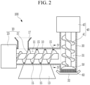
- FIG. 2 shows a schematic cross-sectional lateral side view of a superabsorbent polymer hydrogel shredding device described with reference to FIG. 1
- FIG. 3 shows a schematic diagram of a state in which a barrel spiral is formed on an inner wall of a first barrel body described with reference to FIG. 1
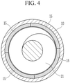
- FIG. 4 shows a cross-sectional view with respect to a line IV-IV of FIG. 2 .
- the superabsorbent polymer hydrogel shredding device 100 includes: a first barrel body 10 in which a first transfer space 11 for transferring a hydrogel is formed and which is formed to extend in a first direction; a first transfer unit 20 installed in the first barrel body 10 and transferring the hydrogel in the first transfer space 11; a second barrel body 30 which is installed on a lateral side of the first barrel body 10, in which a second transfer space 31 connected to the first transfer space 11 is formed in a top-to-bottom direction, and which is formed to extend in a second direction traversing the first direction; a second transfer unit 40 installed in the second barrel body 30 and transferring the hydrogel in the second transfer space 31; a cutter member 50 installed in the second barrel body 30 and pulverizing the hydrogel transferred by the second transfer unit 40; and a porous plate 60 for discharging hydrogel particles pulverized by the cutter member 50 to an outside of the second barrel body 30.
- the first barrel body 10 in which the first transfer space 11 in which the hydrogel is transferred is formed in a length direction may be installed while supported by a bottom side.
- An opened input unit 17 for inputting the hydrogel to the first transfer space 11 may be installed in an upper portion of the first barrel body 10.
- a support base portion 13 may protrude on a lower portion of the first barrel body 10 for the purpose of stable support on the bottom side.
- the first barrel body 10 may be formed to be long in the first direction while settled on the bottom side.
- the first direction may be formed to be long in a cylindrical shape while the first barrel body 10 is settled on the bottom side and is parallel to the bottom side.
- a barrel spiral 15 may protrude inside the first barrel body 10.
- the barrel spiral 15 may be formed to protrude in a plurality of spiral shapes in an opposite direction corresponding to the spiral shape of the first screw member 21 on the inner wall side of the first barrel body 10.
- the barrel spiral 15 is exemplified to protrude on the inner wall side of the first barrel body 10, but the present embodiment is not limited thereto, and the barrel spiral 15 may not protrude.
- the barrel spiral 15 is not limited to the spiral shape, and it may be modifiable in various ways such as a belt-shaped protrusion with a concentric circle on the inner wall side of the first barrel body 10 or a spherical or angulated protrusion protruding corresponding to the spiral position of the first screw member 21.
- the barrel spiral 15 is formed to protrude inside the first barrel body 10, so it is possible to stably transfer the hydrogel without backflow together with an auxiliary shredding operation of the hydrogel.
- the hydrogel may be transferred by the transferring operation of the first transfer unit 20 to be described when input into the first barrel body 10 through the input unit 17.
- the input unit 17 is formed in an opened state in the upper side of the first barrel body 10, so it may be installed to expand on the upper side so that the hydrogel may be easily input to the inside.
- the hydrogel may be transferred in a direction of the second barrel body 30 by a driving force of the first transfer unit 20 when input into the first barrel body 10.
- the first transfer unit 20 is installed in the first barrel body 10, and it may be installed to provide a transfer driving force for transferring the hydrogel.
- the first transfer unit 20 may include a first screw member 21 rotatably installed inside the first transfer space 11 and moving the hydrogel, and a first driving motor 23 for providing the rotation driving force to the first screw member 21.
- the first screw member 21 is rotatably installed in the length direction of the first transfer space 11 inside the first barrel body 10, and it may be installed to be rotated by a driving operation of the first driving motor 23 and to transfer the hydrogel charged in the first transfer space 11 in the direction of the second barrel body 30.
- the first driving motor 23 is installed in the first barrel body 10, while a drive shaft is installed in one end of the first screw member 21, and may be installed to provide a rotation driving force by rotating the first screw member 21 in one direction so that the hydrogel may be transferred at an appropriate transferring rate in the first barrel body 10.
- the first driving motor 23 and the first screw member 21 may be installed to transmit the rotation driving force through a decelerator (not shown).
- the second barrel body 30 may be installed on a lateral side of the first barrel body 10.
- the second barrel body 30 may be formed in a second direction traversing the first direction in which the first barrel body 10 is installed on the lateral side of the first barrel body 10.
- the second direction in which the second barrel body 30 is installed in the first barrel body 10 may be formed to be orthogonal to the first direction that is parallel to the bottom side and to face the bottom side in the present embodiment.
- the second direction of the second barrel body 30 is formed to be a direction that is orthogonal to the first direction
- the embodiment is not limited thereto, and it is also possible to appropriately modify it into a traversing angle in the range of an acute angle or an obtuse angle with respect to the first direction. This will be described in detail according to a third example and a fourth example.
- the second barrel body 30 is installed to be perpendicular to the length direction of the first barrel body 10 on the lateral side of the first barrel body 10 in the first example, which is to change a moving direction of the hydrogel particles transferred in the first transfer space 11 into the gravitational direction.
- the hydrogel particles move in the gravitational direction in the second transfer space 31 of the second barrel body 30, so it is possible to supply them to the porous plate 60 with a uniform pressure. This will be described in detail while the porous plate 60 is described.
- the second transfer unit 40 for transferring the hydrogel transferred to the second transfer space 31 in the direction of an outlet 32 may be installed on the second barrel body 30.
- the second transfer unit 40 may include a second screw member 41 rotatably installed in the second transfer space 31, and a second driving motor 43 for providing a rotation driving force to the second screw member 41.
- the second screw member 41 is installed to be long in the length direction of the second barrel body 30 inside the second transfer space 31, and it may be installed to transfer the hydrogel transferred to the second transfer space 31 through the first transfer space 11 in the direction of the outlet 32.
- the second driving motor 43 is installed in the upper side of the second barrel body 30, and it may be installed so that the drive shaft may be connected to an end of the second screw member 41 to provide a rotation driving force to the second screw member 41.
- the second driving motor 43 and the second screw member 41 may be installed to transmit the rotation driving force through a decelerator (not shown).
- the cutter member 50 may be installed in the second screw member 41 so that it may rotate as the second screw member 41 rotates.
- the cutter member 50 is rotatably installed on the position of the outlet 32 formed in the second barrel body 30 on the second screw member 41, and it may be installed to appropriately pulverize the hydrogel transferred from the second transfer space 31 by the second screw member 41.
- one cutter member 50 will be exemplified to be installed in the end of the second screw member 41.
- the cutter member 50 is not limited to be installed in the end of the second screw member 41, and it is also possible for at least two cutter members 50 to be installed corresponding to a transferring amount of the hydrogel.
- the first driving motor 23 and the second driving motor 43 may be driven at different rotation rates with each other.
- the first driving motor 23 and the second driving motor 43 are operated so that the hydrogel may be supplied to the porous plate 60 installed in the gravitational direction at a further stable rate, so the hydrogel may be further stably transferrable.
- the hydrogel pulverized by the cutter member 50 may be extruded and discharged by the porous plate 60.
- the porous plate 60 is installed at the position of the outlet 32 of the second barrel body 30, and a plurality of shredding holes may be formed therein.
- the hydrogel pulverized by the cutter member 50 is pressurized and moved inside the second barrel body 30 by a pressurizing force generated by a rotation operation of the second screw member 41, so it may be stably discharged through the shredding holes in the porous plate 60.
- the porous plate 60 is made of a heat-treated metal material, so it may stably support the pressurizing force for transferring the hydrogel.
- the second barrel body 30 is installed to be perpendicular to the first barrel body 10 so that it may face the gravitational direction, so the pressurizing force generated by the rotation operation of the second screw member 41 may be uniformly applied to a surface of the porous plate 60.
- the hydrogel is transferred in the second transfer space 31 of the second barrel body 30 and is uniformly pressurized on the surface of the porous plate 60, so it is possible for the hydrogel to pass through the shredding holes of the porous plate 60 and be uniformly shredded.
- the hydrogel shredding device 100 may allow the hydrogel to pass through the porous plate 60 and be shredded while the first barrel body 10 for transferring the hydrogel in the first place and the second barrel body 30 for allowing the outlet 32 to face the gravitational direction is installed on a lateral side of the first barrel body 10. Therefore, the hydrogel is shredded while uniformly pressurized to the porous plate 60 so the hydrogel may be uniformly shredded, and the manufacturing quality of the absorbent polymer may be improved.
- the hydrogel is transferred from the second barrel body 30 installed in the gravitational direction, passes through the porous plate 60, and is shredded, so the hydrogel may be stably shredded without installing an additional backflow preventing member.
- FIG. 5 shows a schematic cross-sectional lateral side view of a superabsorbent polymer hydrogel shredding device according to a second example of the present invention.
- the same reference numerals as those given in FIG. 1 to FIG. 4 represent the same or similar members with the same or similar functions. Those with the same reference numerals will not be described.
- a plurality of the cutter members 150 and the porous plates 160 of the hydrogel shredding device 200 may be installed on the second screw member 41.
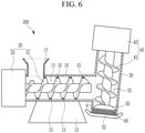
- FIG. 6 shows a schematic cross-sectional lateral side view of a superabsorbent polymer hydrogel shredding device according to a third example of the present invention.
- the same reference numerals as those given in FIG. 1 to FIG. 5 represent the same or similar members with the same or similar functions. Those with the same reference numerals will not be described.
- the first barrel body 30 of the hydrogel shredding device 300 may extend in a first direction that is parallel to the bottom side, and the second barrel body 30 may extend in a second direction traversing the first direction from the lateral side of the first barrel body 10 and may be formed to be inclined with respect to the bottom side.
- the second direction generated by extending the second barrel body 30 may be connected to the first direction generated by extending the first barrel body 10 with an acute angle ( ⁇ ) in an inclined way.
- the second barrel body 30 is formed to be inclined with respect to the first barrel body 10 at an acute angle, so the hydrogel is transferred in an inclined way in the second transfer space 31 of the second barrel body 30 and is pressurized on the surface of the porous plate 60, and it is possible to allow the hydrogel to pass through the shredding holes of the porous plate 60 and be uniformly shredded.
- the hydrogel is moved along the internal space, inclined with an acute angle, of the second barrel body 30 and is shredded on the porous plate 60, so the hydrogel may be stably shredded while it is not steeply lowered.
- FIG. 7 shows a schematic cross-sectional lateral side view of a superabsorbent polymer hydrogel shredding device according to a fourth example of the present invention.
- the same reference numerals as those given in FIG. 1 to FIG. 6 represent the same or similar members with the same or similar functions. Those with the same reference numerals will not be described.
- the first barrel body 30 of the hydrogel shredding device 400 may extend in the first direction in parallel with the bottom side, and the second barrel body 30 may extend in the second direction traversing the first direction from the lateral side of the first barrel body 10, and they may be formed to be inclined with respect to the bottom side.
- the second direction in which the second barrel body 30 extends may be connected to the first direction in which the first barrel body 10 extends at an obtuse angle.
- the hydrogel is moved along the internal space, inclined with an obtuse angle, of the second barrel body 30 and is shredded on the porous plate 60, so the hydrogel may be stably shredded while it is not steeply lowered.
- FIG. 8 shows a schematic cross-sectional lateral side view of a superabsorbent polymer hydrogel shredding device according to a fifth example of the present invention.
- the same reference numerals as those given in FIG. 1 to FIG. 7 represent the same or similar members with the same or similar functions. Those with the same reference numerals will not be described.
- the first direction in which the first barrel body 30 of the hydrogel shredding device 500 according to a fifth example of the present invention extends may extend may be inclined in the ground direction.
- the second direction in which the second barrel body 30 extends may be formed to be long to be perpendicular to the ground.
- first barrel body 10 is formed to be inclined with respect to the ground
- second barrel body 30 is formed to be perpendicular to the ground, so the first barrel body 10 and the second barrel body 30 may be connected to each other in an inclined way.
- the hydrogel may be further actively moved.
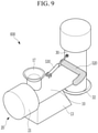
- FIG. 9 shows a perspective view of a superabsorbent polymer hydrogel shredding device according to a sixth example of the present invention
- FIG. 10 shows a schematic cross-sectional lateral side view of a superabsorbent polymer hydrogel shredding device described with reference to FIG. 9
- the same reference numerals as those given in FIG. 1 to FIG. 8 represent the same or similar members with the same or similar functions. Those with the same reference numerals will not be described.
- the second barrel body 30 may be rotatably installed in the first barrel body 10.
- part of the second barrel body 30 may be rotatably installed in the first barrel body 10 by a hinge 510.
- a cover member 520 made of a flexible material may be connected between the second barrel body 30 and the first barrel body 10.
- the second barrel body 30 is a predetermined support member for supporting an installed load and it may be supported on the bottom side.
- a rotation angle of the second barrel body 30 is adjustable by a driver 530 such as a cylinder member.
- the rotation angle by which the second barrel body 30 is installed in the first barrel body 10 is adjustable, so the hydrogel may be fluently shredded by adjusting the transfer angle corresponding to the transferred amount of the hydrogel.
Landscapes
- Engineering & Computer Science (AREA)
- Mechanical Engineering (AREA)
- Food Science & Technology (AREA)
- Manufacturing & Machinery (AREA)
- Addition Polymer Or Copolymer, Post-Treatments, Or Chemical Modifications (AREA)
- Processes Of Treating Macromolecular Substances (AREA)
- Processing And Handling Of Plastics And Other Materials For Molding In General (AREA)
- Solid-Sorbent Or Filter-Aiding Compositions (AREA)
- Disintegrating Or Milling (AREA)
Abstract
Description
- The present invention relates to a superabsorbent polymer hydrogel shredding device for uniformly shredding a hydrogel.
- A superabsorbent polymer (SAP) represents a synthesized polymer material having the function of absorbing moisture that at 500 to 1000 times its own weight, and its manufacturers call it a superabsorbent material (SAM) or an absorbent gel material (AGM). The superabsorbent polymer started being commercialized as menstrual appliances, and it is currently in wide use as hygiene products such as paper diapers, soil repairing agents for gardening, water stops for public works, sheets for raising seedlings, freshness retainers in the food distribution field, and materials for steaming.
- Methods for manufacturing the above-noted superabsorbent polymer include an inverse suspension polymerization based method and a solution polymerization based method. The inverse suspension polymerization is disclosed in, for example,
Japanese Published Patents 56-161408 57-158209 57-198714 - The hydrogel or the hydrogel polymer obtained through the above-noted polymerization reaction is generally pulverized by a drying process and is then sold as a powder. To perform the drying step efficiently, it is important to increase a surface area of the hydrogel polymer to be as big as possible. Therefore, to increase the surface area of the hydrogel polymer to be as big as possible before performing the drying process, a method for increasing the surface area of the hydrogel polymer to be dried by easily pulverizing the hydrogel polymer polymerized by heat polymerization or photopolymerization may be considered. To increase the surface area of the hydrogel polymer as described above, a process for polymerizing the hydrogel polymer and pulverizing it in the first place is disclosed.
- A chopper is generally used in the first process for pulverizing the hydrogel.
- The chopper includes a screw for moving the hydrogel, a barrel including spirals, a cutter blade for cutting the hydrogel, and a porous plate for discharging the cut hydrogel.
- Regarding the conventional chopper, a moving direction of hydrogel particles input to the barrel and the screw is horizontal. Therefore, pressure given to the hydrogel particles on the porous plate disposed position is not uniform, and applied pressure at a lower position of the barrel becomes greater than that at an upper position, so it is not uniformly shredded on the porous plate.
- As described above, when the shredded hydrogel particles do not have a constant size, the particles are dried non-uniformly in the process for drying the hydrogel, so overdried or undried grains may be formed.
- Here, the overdried portion of the hydrogel may generate many fine particles in the process for manufacturing a superabsorbent polymer, and may generate troubles in the manufacturing process. Further, the undried portion of the hydrogel may make it difficult to fluently manufacture a superabsorbent polymer in the process such as pulverization or sorting as well as deteriorating the physical property of the manufactured superabsorbent polymer.
- The above information disclosed in this Background section is only for enhancement of understanding of the background of the invention, and therefore it may contain information that does not form the prior art that is already known in this country to a person of ordinary skill in the art.
- The present invention has been made in an effort to provide a superabsorbent polymer hydrogel shredding device for uniformly shredding a hydrogel and improving manufacturing quality of a superabsorbent polymer.
- An embodiment of the present invention provides a hydrogel shredding device including: a first barrel body in which a first transfer space for transferring a hydrogel is formed, and extending in a first direction; a first transfer unit installed in the first barrel body and transferring the hydrogel in the first transfer space; a second barrel body installed on a lateral side of the first barrel body, and in which a second transfer space connected to the first transfer space extends in a second direction traversing the first direction; a second transfer unit installed in the second barrel body and transferring the hydrogel in the second transfer space; a cutter member installed in the second barrel body and pulverizing the hydrogel transferred by the second transfer unit; and a porous plate for discharging the hydrogel particles pulverized by the cutter member to an outside of the second barrel body.
- The second direction in which the second barrel body extends may be orthogonal to a first direction of the first barrel body, and the second barrel body may be formed in a top to bottom direction.
- The second direction in which the second barrel body extends may represent a traversing direction in an acute angle range with a first direction of the first barrel body, and the second barrel body may be connected to the first barrel body in an inclined way.
- The second direction in which the second barrel body extends may represent a traversing direction in an obtuse angle range with a first direction of the first barrel body, and the second barrel body may be connected to the first barrel body in an inclined way.
- The second direction in which the second barrel body extends may represent a gravitational direction, the first direction in which the first barrel body extends may indicate a direction inclined in a ground direction, and the first barrel body may be connected to the second barrel body in an inclined way.
- A first moving space in which hydrogel particles move may be formed in the first barrel body, and an input unit for inputting the hydrogel particles may be formed on an upper portion of the first barrel body.
- The first transfer unit may include a first screw member rotatably installed inside the first transfer space and moving the hydrogel, and a first driving motor for providing a rotation driving force to the first screw member.
- The second barrel body may be installed on a lateral side of the first barrel body, a second moving space connected to the first transfer space may be formed in a top to bottom direction, and an outlet for discharging pulverized hydrogel particles may be formed on a lower portion.
- The second transfer unit may include a second screw member rotatably installed in the second transfer space and transferring the hydrogel input through the first transfer space in a direction of the outlet, and a second driving motor installed in the second barrel body and providing a rotation driving force to the second screw member.
- The cutter member may be rotatably installed in the second screw member at the position of the outlet.
- The first driving motor and the second driving motor may have different drive shaft rotation speeds.
- A plurality of the cutter members may be installed in the second screw member.
- The second barrel body may be rotatably installed in the first barrel body by a driving operation of a driver.
- The driver may be installed in the first barrel body, and a load member may be a cylinder member rotatably installed on a lateral side of the second barrel body.
- A cover member may be installed around a connection position of the first barrel body and the second barrel body.
- According to the embodiment of the present invention, while the outlet for discharging the hydrogel is positioned in the gravitational direction, the porous plate is installed at the position of the outlet so that the hydrogel may be shredded while the hydrogel is uniformly pressurized to the porous plate, thereby uniformly shredding the hydrogel and improving the manufacturing quality of the absorbent polymer.
- According to the embodiment of the present invention, the hydrogel is transferred in the gravitational direction and is shredded while passing through the porous plate, so the stable shredding process is allowable while not installing a backflow preventing member for preventing the hydrogel from flowing backward.
- According to the embodiment of the present invention, while the outlet for discharging the hydrogel is positioned in an inclined way in a ground direction, the hydrogel is shredded while passing through the porous plate, so the stable shredding process is allowable according to the transferred amount of the hydrogel.
-
-
FIG. 1 shows a perspective view of a superabsorbent polymer hydrogel shredding device according to a first example of the present invention. -
FIG. 2 shows a schematic cross-sectional lateral side view of a superabsorbent polymer hydrogel shredding device described with reference toFIG. 1 . -
FIG. 3 shows a schematic diagram of a state in which a barrel spiral is formed on an inner wall of a first barrel body described with reference toFIG. 1 . -
FIG. 4 shows a cross-sectional view with respect to a line IV-IV ofFIG. 2 . -
FIG. 5 shows a schematic cross-sectional lateral side view of a superabsorbent polymer hydrogel shredding device according to a second example of the present invention. -
FIG. 6 shows a schematic cross-sectional lateral side view of a superabsorbent polymer hydrogel shredding device according to a third example of the present invention. -
FIG. 7 shows a schematic cross-sectional lateral side view of a superabsorbent polymer hydrogel shredding device according to a fourth example of the present invention. -
FIG. 8 shows a schematic cross-sectional lateral side view of a superabsorbent polymer hydrogel shredding device according to a fifth example of the present invention. -
FIG. 9 shows a perspective view of a superabsorbent polymer hydrogel shredding device according to a sixth example of the present invention. -
FIG. 10 shows a schematic cross-sectional lateral side view of a superabsorbent polymer hydrogel shredding device described with reference toFIG. 9 . - The present invention will be described more fully hereinafter with reference to the accompanying drawings, in which embodiments of the invention are shown. As those skilled in the art would realize, the described embodiments may be modified in various different ways, all without departing from the scope of the present invention. The drawings and description are to be regarded as illustrative in nature and not restrictive, and like reference numerals designate like elements throughout the specification.
-
FIG. 1 shows a perspective view of a superabsorbent polymer hydrogel shredding device according to a first example of the present invention,FIG. 2 shows a schematic cross-sectional lateral side view of a superabsorbent polymer hydrogel shredding device described with reference toFIG. 1 , andFIG. 3 shows a schematic diagram of a state in which a barrel spiral is formed on an inner wall of a first barrel body described with reference toFIG. 1 . Also,FIG. 4 shows a cross-sectional view with respect to a line IV-IV ofFIG. 2 . - As shown in
FIG. 1 to FIG. 4 , the superabsorbent polymerhydrogel shredding device 100 according to a first example of the present invention includes: afirst barrel body 10 in which afirst transfer space 11 for transferring a hydrogel is formed and which is formed to extend in a first direction; afirst transfer unit 20 installed in thefirst barrel body 10 and transferring the hydrogel in thefirst transfer space 11; asecond barrel body 30 which is installed on a lateral side of thefirst barrel body 10, in which asecond transfer space 31 connected to thefirst transfer space 11 is formed in a top-to-bottom direction, and which is formed to extend in a second direction traversing the first direction; asecond transfer unit 40 installed in thesecond barrel body 30 and transferring the hydrogel in thesecond transfer space 31; acutter member 50 installed in thesecond barrel body 30 and pulverizing the hydrogel transferred by thesecond transfer unit 40; and aporous plate 60 for discharging hydrogel particles pulverized by thecutter member 50 to an outside of thesecond barrel body 30. - The
first barrel body 10 in which thefirst transfer space 11 in which the hydrogel is transferred is formed in a length direction may be installed while supported by a bottom side. - An opened
input unit 17 for inputting the hydrogel to thefirst transfer space 11 may be installed in an upper portion of thefirst barrel body 10. - A
support base portion 13 may protrude on a lower portion of thefirst barrel body 10 for the purpose of stable support on the bottom side. - The
first barrel body 10 may be formed to be long in the first direction while settled on the bottom side. Here, the first direction may be formed to be long in a cylindrical shape while thefirst barrel body 10 is settled on the bottom side and is parallel to the bottom side. - A
barrel spiral 15 may protrude inside thefirst barrel body 10. - As shown in
FIG. 3 , thebarrel spiral 15 may be formed to protrude in a plurality of spiral shapes in an opposite direction corresponding to the spiral shape of thefirst screw member 21 on the inner wall side of thefirst barrel body 10. In the present embodiment, thebarrel spiral 15 is exemplified to protrude on the inner wall side of thefirst barrel body 10, but the present embodiment is not limited thereto, and thebarrel spiral 15 may not protrude. - The barrel spiral 15 is not limited to the spiral shape, and it may be modifiable in various ways such as a belt-shaped protrusion with a concentric circle on the inner wall side of the
first barrel body 10 or a spherical or angulated protrusion protruding corresponding to the spiral position of thefirst screw member 21. - As described, the
barrel spiral 15 is formed to protrude inside thefirst barrel body 10, so it is possible to stably transfer the hydrogel without backflow together with an auxiliary shredding operation of the hydrogel. - The hydrogel may be transferred by the transferring operation of the
first transfer unit 20 to be described when input into thefirst barrel body 10 through theinput unit 17. - The
input unit 17 is formed in an opened state in the upper side of thefirst barrel body 10, so it may be installed to expand on the upper side so that the hydrogel may be easily input to the inside. - As described, the hydrogel may be transferred in a direction of the
second barrel body 30 by a driving force of thefirst transfer unit 20 when input into thefirst barrel body 10. - The
first transfer unit 20 is installed in thefirst barrel body 10, and it may be installed to provide a transfer driving force for transferring the hydrogel. - In detail, the
first transfer unit 20 may include afirst screw member 21 rotatably installed inside thefirst transfer space 11 and moving the hydrogel, and afirst driving motor 23 for providing the rotation driving force to thefirst screw member 21. - The
first screw member 21 is rotatably installed in the length direction of thefirst transfer space 11 inside thefirst barrel body 10, and it may be installed to be rotated by a driving operation of thefirst driving motor 23 and to transfer the hydrogel charged in thefirst transfer space 11 in the direction of thesecond barrel body 30. - The
first driving motor 23 is installed in thefirst barrel body 10, while a drive shaft is installed in one end of thefirst screw member 21, and may be installed to provide a rotation driving force by rotating thefirst screw member 21 in one direction so that the hydrogel may be transferred at an appropriate transferring rate in thefirst barrel body 10. - The
first driving motor 23 and thefirst screw member 21 may be installed to transmit the rotation driving force through a decelerator (not shown). - The
second barrel body 30 may be installed on a lateral side of thefirst barrel body 10. - The
second barrel body 30 may be formed in a second direction traversing the first direction in which thefirst barrel body 10 is installed on the lateral side of thefirst barrel body 10. - The second direction in which the
second barrel body 30 is installed in thefirst barrel body 10 may be formed to be orthogonal to the first direction that is parallel to the bottom side and to face the bottom side in the present embodiment. - However, while the second direction of the
second barrel body 30 is formed to be a direction that is orthogonal to the first direction, the embodiment is not limited thereto, and it is also possible to appropriately modify it into a traversing angle in the range of an acute angle or an obtuse angle with respect to the first direction. This will be described in detail according to a third example and a fourth example. - The
second barrel body 30 is installed to be perpendicular to the length direction of thefirst barrel body 10 on the lateral side of thefirst barrel body 10 in the first example, which is to change a moving direction of the hydrogel particles transferred in thefirst transfer space 11 into the gravitational direction. - Therefore, the hydrogel particles move in the gravitational direction in the
second transfer space 31 of thesecond barrel body 30, so it is possible to supply them to theporous plate 60 with a uniform pressure. This will be described in detail while theporous plate 60 is described. - The
second transfer unit 40 for transferring the hydrogel transferred to thesecond transfer space 31 in the direction of anoutlet 32 may be installed on thesecond barrel body 30. - The
second transfer unit 40 may include asecond screw member 41 rotatably installed in thesecond transfer space 31, and asecond driving motor 43 for providing a rotation driving force to thesecond screw member 41. - The
second screw member 41 is installed to be long in the length direction of thesecond barrel body 30 inside thesecond transfer space 31, and it may be installed to transfer the hydrogel transferred to thesecond transfer space 31 through thefirst transfer space 11 in the direction of theoutlet 32. - The
second driving motor 43 is installed in the upper side of thesecond barrel body 30, and it may be installed so that the drive shaft may be connected to an end of thesecond screw member 41 to provide a rotation driving force to thesecond screw member 41. - The
second driving motor 43 and thesecond screw member 41 may be installed to transmit the rotation driving force through a decelerator (not shown). - In addition, the
cutter member 50 may be installed in thesecond screw member 41 so that it may rotate as thesecond screw member 41 rotates. - The
cutter member 50 is rotatably installed on the position of theoutlet 32 formed in thesecond barrel body 30 on thesecond screw member 41, and it may be installed to appropriately pulverize the hydrogel transferred from thesecond transfer space 31 by thesecond screw member 41. - In the present embodiment, one
cutter member 50 will be exemplified to be installed in the end of thesecond screw member 41. However, thecutter member 50 is not limited to be installed in the end of thesecond screw member 41, and it is also possible for at least twocutter members 50 to be installed corresponding to a transferring amount of the hydrogel. - The
first driving motor 23 and thesecond driving motor 43 may be driven at different rotation rates with each other. - That is, it is possible to differentiate the transferring rate for the hydrogel to move in the
first barrel body 10 by driving thefirst driving motor 23 and the transferring rate for the hydrogel to be transferred in the direction of theporous plate 60 in thesecond barrel body 30 by driving thesecond driving motor 43. - Therefore, the
first driving motor 23 and thesecond driving motor 43 are operated so that the hydrogel may be supplied to theporous plate 60 installed in the gravitational direction at a further stable rate, so the hydrogel may be further stably transferrable. - The hydrogel pulverized by the
cutter member 50 may be extruded and discharged by theporous plate 60. - The
porous plate 60 is installed at the position of theoutlet 32 of thesecond barrel body 30, and a plurality of shredding holes may be formed therein. Hence, the hydrogel pulverized by thecutter member 50 is pressurized and moved inside thesecond barrel body 30 by a pressurizing force generated by a rotation operation of thesecond screw member 41, so it may be stably discharged through the shredding holes in theporous plate 60. - The
porous plate 60 is made of a heat-treated metal material, so it may stably support the pressurizing force for transferring the hydrogel. - Here, the
second barrel body 30 is installed to be perpendicular to thefirst barrel body 10 so that it may face the gravitational direction, so the pressurizing force generated by the rotation operation of thesecond screw member 41 may be uniformly applied to a surface of theporous plate 60. - Therefore, the hydrogel is transferred in the
second transfer space 31 of thesecond barrel body 30 and is uniformly pressurized on the surface of theporous plate 60, so it is possible for the hydrogel to pass through the shredding holes of theporous plate 60 and be uniformly shredded. - As described above, the
hydrogel shredding device 100 according to the present embodiment may allow the hydrogel to pass through theporous plate 60 and be shredded while thefirst barrel body 10 for transferring the hydrogel in the first place and thesecond barrel body 30 for allowing theoutlet 32 to face the gravitational direction is installed on a lateral side of thefirst barrel body 10. Therefore, the hydrogel is shredded while uniformly pressurized to theporous plate 60 so the hydrogel may be uniformly shredded, and the manufacturing quality of the absorbent polymer may be improved. - In addition, the hydrogel is transferred from the
second barrel body 30 installed in the gravitational direction, passes through theporous plate 60, and is shredded, so the hydrogel may be stably shredded without installing an additional backflow preventing member. -
FIG. 5 shows a schematic cross-sectional lateral side view of a superabsorbent polymer hydrogel shredding device according to a second example of the present invention. The same reference numerals as those given inFIG. 1 to FIG. 4 represent the same or similar members with the same or similar functions. Those with the same reference numerals will not be described. - As shown in
FIG. 5 , a plurality of thecutter members 150 and theporous plates 160 of thehydrogel shredding device 200 according to a second example of the present invention may be installed on thesecond screw member 41. - Therefore, it is possible to pulverize the hydrogel by use of a plurality of
cutter members 150 according to the rotation operation of thesecond screw member 41, so it is possible to efficiently pulverize the hydrogel. -
FIG. 6 shows a schematic cross-sectional lateral side view of a superabsorbent polymer hydrogel shredding device according to a third example of the present invention. The same reference numerals as those given inFIG. 1 to FIG. 5 represent the same or similar members with the same or similar functions. Those with the same reference numerals will not be described. - As shown in
FIG. 6 , thefirst barrel body 30 of thehydrogel shredding device 300 according to a third example of the present invention may extend in a first direction that is parallel to the bottom side, and thesecond barrel body 30 may extend in a second direction traversing the first direction from the lateral side of thefirst barrel body 10 and may be formed to be inclined with respect to the bottom side. - In the third example, the second direction generated by extending the
second barrel body 30 may be connected to the first direction generated by extending thefirst barrel body 10 with an acute angle (α) in an inclined way. - As described, the
second barrel body 30 is formed to be inclined with respect to thefirst barrel body 10 at an acute angle, so the hydrogel is transferred in an inclined way in thesecond transfer space 31 of thesecond barrel body 30 and is pressurized on the surface of theporous plate 60, and it is possible to allow the hydrogel to pass through the shredding holes of theporous plate 60 and be uniformly shredded. - Therefore, the hydrogel is moved along the internal space, inclined with an acute angle, of the
second barrel body 30 and is shredded on theporous plate 60, so the hydrogel may be stably shredded while it is not steeply lowered. -
FIG. 7 shows a schematic cross-sectional lateral side view of a superabsorbent polymer hydrogel shredding device according to a fourth example of the present invention. The same reference numerals as those given inFIG. 1 to FIG. 6 represent the same or similar members with the same or similar functions. Those with the same reference numerals will not be described. - As shown in
FIG. 7 , thefirst barrel body 30 of thehydrogel shredding device 400 according to a fourth example of the present invention may extend in the first direction in parallel with the bottom side, and thesecond barrel body 30 may extend in the second direction traversing the first direction from the lateral side of thefirst barrel body 10, and they may be formed to be inclined with respect to the bottom side. - In the fourth example, the second direction in which the
second barrel body 30 extends may be connected to the first direction in which thefirst barrel body 10 extends at an obtuse angle. - Therefore, the hydrogel is moved along the internal space, inclined with an obtuse angle, of the
second barrel body 30 and is shredded on theporous plate 60, so the hydrogel may be stably shredded while it is not steeply lowered. -
FIG. 8 shows a schematic cross-sectional lateral side view of a superabsorbent polymer hydrogel shredding device according to a fifth example of the present invention. The same reference numerals as those given inFIG. 1 to FIG. 7 represent the same or similar members with the same or similar functions. Those with the same reference numerals will not be described. - As shown in
FIG. 8 , the first direction in which thefirst barrel body 30 of thehydrogel shredding device 500 according to a fifth example of the present invention extends may extend may be inclined in the ground direction. - The second direction in which the
second barrel body 30 extends may be formed to be long to be perpendicular to the ground. - That is, the
first barrel body 10 is formed to be inclined with respect to the ground, and thesecond barrel body 30 is formed to be perpendicular to the ground, so thefirst barrel body 10 and thesecond barrel body 30 may be connected to each other in an inclined way. - As described, as the
first barrel body 10 is formed to be inclined in the ground direction, the hydrogel may be further actively moved. -
FIG. 9 shows a perspective view of a superabsorbent polymer hydrogel shredding device according to a sixth example of the present invention, andFIG. 10 shows a schematic cross-sectional lateral side view of a superabsorbent polymer hydrogel shredding device described with reference toFIG. 9 . The same reference numerals as those given inFIG. 1 to FIG. 8 represent the same or similar members with the same or similar functions. Those with the same reference numerals will not be described. - As shown in
FIG. 9 andFIG. 10 , regarding thehydrogel shredding device 600 according to a sixth example of the present invention, thesecond barrel body 30 may be rotatably installed in thefirst barrel body 10. - That is, part of the
second barrel body 30 may be rotatably installed in thefirst barrel body 10 by ahinge 510. Acover member 520 made of a flexible material may be connected between thesecond barrel body 30 and thefirst barrel body 10. Here, thesecond barrel body 30 is a predetermined support member for supporting an installed load and it may be supported on the bottom side. - In another way, a rotation angle of the
second barrel body 30 is adjustable by adriver 530 such as a cylinder member. - As described, the rotation angle by which the
second barrel body 30 is installed in thefirst barrel body 10 is adjustable, so the hydrogel may be fluently shredded by adjusting the transfer angle corresponding to the transferred amount of the hydrogel. - While this invention has been described in connection with what is presently considered to be practical exemplary embodiments, it is to be understood that the invention is not limited to the disclosed embodiments, but, on the contrary, is intended to cover various modifications and equivalent arrangements included within the scope of the appended claims.
-
- 10...
first barrel body 11...first transfer space - 13...
support base portion 15... barrel spiral - 17...
input unit 20...first transfer unit - 21 ...
first screw member 23...first driving motor - 30...
second barrel body 31...second transfer space - 40...
second transfer unit 41...second screw member - 43...second driving
motor - 60, 160...
porous plate 510..hinge - 520..
cover member 530..driver
Claims (15)
- A hydrogel shredding device comprising:a first barrel body in which a first transfer space for transferring a hydrogel is formed, and extending in a first direction;a first transfer unit installed in the first barrel body and transferring the hydrogel in the first transfer space;a second barrel body installed on a lateral side of the first barrel body, and in which a second transfer space connected to the first transfer space extends in a second direction traversing the first direction;a second transfer unit installed in the second barrel body and transferring the hydrogel in the second transfer space;a cutter member installed in the second barrel body and pulverizing the hydrogel transferred by the second transfer unit; anda porous plate for discharging hydrogel particles pulverized by the cutter member to an outside of the second barrel body.
- The hydrogel shredding device of claim 1, wherein
the second direction in which the second barrel body extends is orthogonal to the first direction of the first barrel body, and the second barrel body is formed in a top to bottom direction. - The hydrogel shredding device of claim 1, wherein
the second direction in which the second barrel body extends represents a traversing direction in an acute angle range with the first direction of the first barrel body, and the second barrel body is connected to the first barrel body in an inclined way. - The hydrogel shredding device of claim 1, wherein
the second direction in which the second barrel body extends represents a traversing direction in an obtuse angle range with the first direction of the first barrel body, and the second barrel body is connected to the first barrel body in an inclined way. - The hydrogel shredding device of claim 1, wherein
the second direction in which the second barrel body extends represents a gravitational direction, the first direction in which the first barrel body extends indicates a direction inclined in a ground direction, and the first barrel body is connected to the second barrel body in an inclined way. - The hydrogel shredding device of claim 1, wherein
a first moving space in which hydrogel particles move is formed in the first barrel body, and an input unit for inputting the hydrogel particles is formed on an upper portion of the first barrel body. - The hydrogel shredding device of claim 6, whereinthe first transfer unit includesa first screw member rotatably installed inside the first transfer space and moving the hydrogel, anda first driving motor for providing a rotation driving force to the first screw member.
- The hydrogel shredding device of claim 7, wherein
the second barrel body is installed on a lateral side of the first barrel body, a second moving space connected to the first transfer space is formed in a top to bottom direction, and an outlet for discharging pulverized hydrogel particles is formed on a lower portion. - The hydrogel shredding device of claim 8, whereinthe second transfer unit includesa second screw member rotatably installed in the second transfer space and transferring the hydrogel input through the first transfer space in a direction of the outlet, anda second driving motor installed in the second barrel body and providing a rotation driving force to the second screw member.
- The hydrogel shredding device of claim 9, wherein
the cutter member is rotatably installed in the second screw member at a position of the outlet. - The hydrogel shredding device of claim 10, wherein
the first driving motor and the second driving motor have different drive shaft rotation speeds. - The hydrogel shredding device of claim 11, wherein
a plurality of the cutter members are installed in the second screw member. - The hydrogel shredding device of claim 1, wherein
the second barrel body is rotatably installed in the first barrel body by a driving operation of a driver. - The hydrogel shredding device of claim 13, wherein
the driver is installed in the first barrel body, and a load member is a cylinder member rotatably installed on a lateral side of the second barrel body. - The hydrogel shredding device of claim 14, wherein
a cover member is installed around a connection position of the first barrel body and the second barrel body.
Applications Claiming Priority (3)
| Application Number | Priority Date | Filing Date | Title |
|---|---|---|---|
| KR20190115487 | 2019-09-19 | ||
| KR1020200050855A KR102468197B1 (en) | 2019-09-19 | 2020-04-27 | Minute cutting apparatus for super absorbent polymer hydrous gel |
| PCT/KR2020/006215 WO2021054564A1 (en) | 2019-09-19 | 2020-05-12 | Fine-cutting apparatus for super absorbent polymer hydrogel |
Publications (3)
| Publication Number | Publication Date |
|---|---|
| EP3939756A1 true EP3939756A1 (en) | 2022-01-19 |
| EP3939756A4 EP3939756A4 (en) | 2022-06-01 |
| EP3939756B1 EP3939756B1 (en) | 2023-11-08 |
Family
ID=74884640
Family Applications (1)
| Application Number | Title | Priority Date | Filing Date |
|---|---|---|---|
| EP20864628.1A Active EP3939756B1 (en) | 2019-09-19 | 2020-05-12 | Fine-cutting device for cutting a super-absorbent polymer hydrogel |
Country Status (4)
| Country | Link |
|---|---|
| US (1) | US11975335B2 (en) |
| EP (1) | EP3939756B1 (en) |
| JP (1) | JP7282438B2 (en) |
| WO (1) | WO2021054564A1 (en) |
Cited By (6)
| Publication number | Priority date | Publication date | Assignee | Title |
|---|---|---|---|---|
| EP3984711A4 (en) * | 2019-11-21 | 2022-08-24 | LG Chem, Ltd. | COMPOSITE CHOPPER FOR SUPERABSORBENT HYDROGEL |
| EP4000736A4 (en) * | 2019-10-18 | 2022-09-14 | LG Chem, Ltd. | SUPER ABSORBENT POLYMER HYDROGEL GRINDER USING A PUMP |
| EP4011576A4 (en) * | 2020-02-28 | 2022-12-07 | LG Chem, Ltd. | SUPERABSORBENT POLYMER HYDROGEL Chopper |
| EP4197639A4 (en) * | 2021-06-18 | 2024-01-24 | Lg Chem, Ltd. | MICRONIZATION DEVICE FOR HYDROGEL MADE OF SUPERABSORBENT POLYMER |
| US12491662B2 (en) | 2019-10-18 | 2025-12-09 | Lg Chem, Ltd. | Minute cutting apparatus for super absorbent polymer hydrogel using pump |
| US12521726B2 (en) | 2021-06-18 | 2026-01-13 | Lg Chem, Ltd. | Micronizing apparatus for hydrogel of super absorbent polymer |
Families Citing this family (3)
| Publication number | Priority date | Publication date | Assignee | Title |
|---|---|---|---|---|
| CN116113502A (en) * | 2021-06-18 | 2023-05-12 | 株式会社Lg化学 | Micronization device for superabsorbent polymer hydrogel |
| CN113580411A (en) * | 2021-08-05 | 2021-11-02 | 徐州莫大新材料科技有限公司 | Grain device is cut to polymer water absorption gel material that keeps water |
| KR20230119475A (en) * | 2022-02-07 | 2023-08-16 | 주식회사 엘지화학 | Micronizing apparatus for hydrogel of super absorbent polymer |
Family Cites Families (26)
| Publication number | Priority date | Publication date | Assignee | Title |
|---|---|---|---|---|
| JPS56161408A (en) | 1980-05-19 | 1981-12-11 | Kao Corp | Production of water-absorbing resin |
| JPS57158209A (en) | 1981-03-25 | 1982-09-30 | Kao Corp | Production of bead-form highly water-absorbing polymer |
| JPS57198714A (en) | 1981-05-29 | 1982-12-06 | Sumitomo Chem Co Ltd | Production of hydrogel |
| JPS61154810A (en) | 1984-12-27 | 1986-07-14 | Japan Steel Works Ltd:The | Method and apparatus for stabilized processing of acetal copolymer at high speed |
| GB9511511D0 (en) * | 1995-06-07 | 1995-08-02 | Trim Masters Int Ltd | Polymer processing apparatus |
| JPH0940416A (en) | 1995-07-31 | 1997-02-10 | Mitsubishi Chem Corp | Method for producing powdery gel |
| JP4920182B2 (en) | 2003-09-01 | 2012-04-18 | 株式会社日本触媒 | Method for producing water absorbent resin particles |
| DE602004004840T2 (en) | 2003-09-01 | 2007-10-31 | Nippon Shokubai Co. Ltd. | Process for the preparation of water-absorbent resin particles from hydrogel particles |
| RU2006114036A (en) | 2003-09-26 | 2006-08-27 | Ибара Корпорейшн (JP) | SYSTEM FOR REMOVING NON-COMBUSTIBLE MATERIALS FROM A FURNACE WITH A PSEUDO-LIQUID LAYER |
| KR200410208Y1 (en) | 2005-12-13 | 2006-03-07 | 김원한 | Transverse Boom Refractor for Feed Carrier |
| CN201002042Y (en) | 2007-01-29 | 2008-01-09 | 赵巧宝 | Double-faced mincing and cutting knife for material mincing machine |
| US8329844B2 (en) | 2008-04-30 | 2012-12-11 | Basf Se | Process for producing water-absorbing polymer particles |
| KR101105388B1 (en) | 2008-09-12 | 2012-01-16 | 최기홍 | How to Make Grain Puffed Snacks |
| KR101296847B1 (en) | 2011-04-06 | 2013-08-14 | 주식회사델리스 | Apparatus for puffing grains |
| EP3520978B1 (en) | 2013-08-28 | 2020-11-04 | Nippon Shokubai Co., Ltd. | Polyacrylic acid (salt)-based water absorbent resin powder |
| KR102472803B1 (en) | 2014-09-29 | 2022-12-01 | 가부시키가이샤 닛폰 쇼쿠바이 | Water-absorbable resin powder, and method for determining elastic modulus of water-absorbable resin powder |
| CN204354342U (en) | 2014-12-23 | 2015-05-27 | 浙江华江科技发展有限公司 | Two continuously mixing feeding units of a kind of automobile-used waste and old GMT material recovery granulation |
| CN204869324U (en) * | 2015-08-28 | 2015-12-16 | 方瑞庭 | Dustless manufacturing installation of aminoplast moulding compound |
| US10316120B2 (en) | 2015-09-18 | 2019-06-11 | Aquapak Polymer Limited | Process and apparatus for manufacture of processable polyvinyl alcohol |
| KR101586465B1 (en) * | 2015-09-30 | 2016-01-19 | 우성환 | Device for pulverization and extraction of agricultural product |
| CN206030293U (en) | 2016-08-30 | 2017-03-22 | 陕西国防工业职业技术学院 | Super absorbent polymer resin particles apparatus for producing |
| CN207327544U (en) | 2017-03-10 | 2018-05-08 | 浙江越拓新材料科技有限公司 | Phenolic moulding powder is granulated and uses single screw rod feeding machine |
| CN207566348U (en) | 2017-11-03 | 2018-07-03 | 中国石油天然气集团公司 | Landwaste conveying device |
| CN207736564U (en) * | 2017-12-06 | 2018-08-17 | 东莞市天泰塑胶电业有限公司 | A screw conveying mechanism of a twin-screw granulator |
| CN209241964U (en) | 2018-12-24 | 2019-08-13 | 泉州市康馨化工科技有限公司 | A kind of chemical industry feeding device |
| JP7305254B2 (en) | 2019-10-18 | 2023-07-10 | エルジー・ケム・リミテッド | Water-containing gel shredding device using a pump |
-
2020
- 2020-05-12 US US17/608,030 patent/US11975335B2/en active Active
- 2020-05-12 JP JP2021562149A patent/JP7282438B2/en active Active
- 2020-05-12 EP EP20864628.1A patent/EP3939756B1/en active Active
- 2020-05-12 WO PCT/KR2020/006215 patent/WO2021054564A1/en not_active Ceased
Cited By (8)
| Publication number | Priority date | Publication date | Assignee | Title |
|---|---|---|---|---|
| EP4000736A4 (en) * | 2019-10-18 | 2022-09-14 | LG Chem, Ltd. | SUPER ABSORBENT POLYMER HYDROGEL GRINDER USING A PUMP |
| US12491662B2 (en) | 2019-10-18 | 2025-12-09 | Lg Chem, Ltd. | Minute cutting apparatus for super absorbent polymer hydrogel using pump |
| EP3984711A4 (en) * | 2019-11-21 | 2022-08-24 | LG Chem, Ltd. | COMPOSITE CHOPPER FOR SUPERABSORBENT HYDROGEL |
| US12251856B2 (en) | 2019-11-21 | 2025-03-18 | Lg Chem, Ltd. | Complex minute cutting apparatus for super absorbent polymer hydrogel |
| EP4011576A4 (en) * | 2020-02-28 | 2022-12-07 | LG Chem, Ltd. | SUPERABSORBENT POLYMER HYDROGEL Chopper |
| US12145287B2 (en) | 2020-02-28 | 2024-11-19 | Lg Chem, Ltd. | Superabsorbent polymer hydrogel chopping device |
| EP4197639A4 (en) * | 2021-06-18 | 2024-01-24 | Lg Chem, Ltd. | MICRONIZATION DEVICE FOR HYDROGEL MADE OF SUPERABSORBENT POLYMER |
| US12521726B2 (en) | 2021-06-18 | 2026-01-13 | Lg Chem, Ltd. | Micronizing apparatus for hydrogel of super absorbent polymer |
Also Published As
| Publication number | Publication date |
|---|---|
| JP7282438B2 (en) | 2023-05-29 |
| EP3939756B1 (en) | 2023-11-08 |
| JP2022529704A (en) | 2022-06-23 |
| BR112021022743A2 (en) | 2022-01-11 |
| WO2021054564A1 (en) | 2021-03-25 |
| EP3939756A4 (en) | 2022-06-01 |
| US11975335B2 (en) | 2024-05-07 |
| US20220203375A1 (en) | 2022-06-30 |
Similar Documents
| Publication | Publication Date | Title |
|---|---|---|
| US11975335B2 (en) | Super absorbent polymer hydrogel shredding device | |
| CN114096388B (en) | Composite fine cutting device for super absorbent hydrogel | |
| JP7305254B2 (en) | Water-containing gel shredding device using a pump | |
| CN114340859A (en) | Superabsorbent polymer hydrogel chopping device | |
| EP4000736B1 (en) | Superabsorbent polymer hydrogel chopper using pump | |
| JP7136780B2 (en) | Single-screw extruder and use of single-screw extruder and method of using single-screw extruder to change the morphology of superabsorbent polymers, SAP polymer gels | |
| JP7334289B2 (en) | Belt drying apparatus for drying aqueous polymer gels and for crushing dry polymer gels into dry polymer particles, and for drying aqueous polymer gels and for crushing dry polymer gels into dry polymer particles the method of | |
| KR102500922B1 (en) | A belt dryer arrangement for drying an aqueous polymer gel and comminuting the dry polymer gel to provide dry polymer particles and a process for drying an aqueous polymer gel and comminution of the dry polymer gel to provide dry polymer particles | |
| CN113727780B (en) | Superabsorbent polymer hydrogel shredding device | |
| BR112021022743B1 (en) | SUPERABSORBENT HYDROGEL POLYMER FRAGMENTATION DEVICE | |
| KR102412599B1 (en) | Drying apparatus for absorbent polymer and drying method using the same | |
| AT411342B (en) | Thermoplastic particle granulator, heater and homogenizer comprises a container with a an angled base and rotated flat blade carrier or a rotated blade carrier disc with a turned up edge | |
| KR20210110169A (en) | Minute cutting apparatus for super absorbent polymer hydrous gel |
Legal Events
| Date | Code | Title | Description |
|---|---|---|---|
| STAA | Information on the status of an ep patent application or granted ep patent |
Free format text: STATUS: THE INTERNATIONAL PUBLICATION HAS BEEN MADE |
|
| PUAI | Public reference made under article 153(3) epc to a published international application that has entered the european phase |
Free format text: ORIGINAL CODE: 0009012 |
|
| STAA | Information on the status of an ep patent application or granted ep patent |
Free format text: STATUS: REQUEST FOR EXAMINATION WAS MADE |
|
| 17P | Request for examination filed |
Effective date: 20211015 |
|
| AK | Designated contracting states |
Kind code of ref document: A1 Designated state(s): AL AT BE BG CH CY CZ DE DK EE ES FI FR GB GR HR HU IE IS IT LI LT LU LV MC MK MT NL NO PL PT RO RS SE SI SK SM TR |
|
| REG | Reference to a national code |
Ref country code: DE Ref legal event code: R079 Free format text: PREVIOUS MAIN CLASS: B26D0005220000 Ipc: B29B0007420000 Ref document number: 602020020875 Country of ref document: DE |
|
| A4 | Supplementary search report drawn up and despatched |
Effective date: 20220503 |
|
| RIC1 | Information provided on ipc code assigned before grant |
Ipc: B26D 7/06 20060101ALI20220426BHEP Ipc: B26D 5/22 20060101ALI20220426BHEP Ipc: B26D 3/00 20060101ALI20220426BHEP Ipc: B01J 2/20 20060101ALI20220426BHEP Ipc: B29B 9/12 20060101ALI20220426BHEP Ipc: B29B 9/06 20060101ALI20220426BHEP Ipc: B29B 7/42 20060101AFI20220426BHEP |
|
| DAV | Request for validation of the european patent (deleted) | ||
| DAX | Request for extension of the european patent (deleted) | ||
| STAA | Information on the status of an ep patent application or granted ep patent |
Free format text: STATUS: EXAMINATION IS IN PROGRESS |
|
| 17Q | First examination report despatched |
Effective date: 20230330 |
|
| GRAP | Despatch of communication of intention to grant a patent |
Free format text: ORIGINAL CODE: EPIDOSNIGR1 |
|
| STAA | Information on the status of an ep patent application or granted ep patent |
Free format text: STATUS: GRANT OF PATENT IS INTENDED |
|
| INTG | Intention to grant announced |
Effective date: 20230818 |
|
| RIC1 | Information provided on ipc code assigned before grant |
Ipc: C08J 3/12 20060101ALN20230804BHEP Ipc: B29B 9/12 20060101ALI20230804BHEP Ipc: B29B 9/06 20060101ALI20230804BHEP Ipc: B29B 7/42 20060101AFI20230804BHEP |
|
| GRAS | Grant fee paid |
Free format text: ORIGINAL CODE: EPIDOSNIGR3 |
|
| GRAA | (expected) grant |
Free format text: ORIGINAL CODE: 0009210 |
|
| STAA | Information on the status of an ep patent application or granted ep patent |
Free format text: STATUS: THE PATENT HAS BEEN GRANTED |
|
| AK | Designated contracting states |
Kind code of ref document: B1 Designated state(s): AL AT BE BG CH CY CZ DE DK EE ES FI FR GB GR HR HU IE IS IT LI LT LU LV MC MK MT NL NO PL PT RO RS SE SI SK SM TR |
|
| REG | Reference to a national code |
Ref country code: GB Ref legal event code: FG4D |
|
| REG | Reference to a national code |
Ref country code: CH Ref legal event code: EP |
|
| REG | Reference to a national code |
Ref country code: DE Ref legal event code: R096 Ref document number: 602020020875 Country of ref document: DE |
|
| REG | Reference to a national code |
Ref country code: IE Ref legal event code: FG4D |
|
| REG | Reference to a national code |
Ref country code: LT Ref legal event code: MG9D |
|
| REG | Reference to a national code |
Ref country code: NL Ref legal event code: MP Effective date: 20231108 |
|
| PG25 | Lapsed in a contracting state [announced via postgrant information from national office to epo] |
Ref country code: GR Free format text: LAPSE BECAUSE OF FAILURE TO SUBMIT A TRANSLATION OF THE DESCRIPTION OR TO PAY THE FEE WITHIN THE PRESCRIBED TIME-LIMIT Effective date: 20240209 |
|
| PG25 | Lapsed in a contracting state [announced via postgrant information from national office to epo] |
Ref country code: IS Free format text: LAPSE BECAUSE OF FAILURE TO SUBMIT A TRANSLATION OF THE DESCRIPTION OR TO PAY THE FEE WITHIN THE PRESCRIBED TIME-LIMIT Effective date: 20240308 |
|
| PG25 | Lapsed in a contracting state [announced via postgrant information from national office to epo] |
Ref country code: LT Free format text: LAPSE BECAUSE OF FAILURE TO SUBMIT A TRANSLATION OF THE DESCRIPTION OR TO PAY THE FEE WITHIN THE PRESCRIBED TIME-LIMIT Effective date: 20231108 |
|
| REG | Reference to a national code |
Ref country code: AT Ref legal event code: MK05 Ref document number: 1629241 Country of ref document: AT Kind code of ref document: T Effective date: 20231108 |
|
| PG25 | Lapsed in a contracting state [announced via postgrant information from national office to epo] |
Ref country code: NL Free format text: LAPSE BECAUSE OF FAILURE TO SUBMIT A TRANSLATION OF THE DESCRIPTION OR TO PAY THE FEE WITHIN THE PRESCRIBED TIME-LIMIT Effective date: 20231108 |
|
| PG25 | Lapsed in a contracting state [announced via postgrant information from national office to epo] |
Ref country code: AT Free format text: LAPSE BECAUSE OF FAILURE TO SUBMIT A TRANSLATION OF THE DESCRIPTION OR TO PAY THE FEE WITHIN THE PRESCRIBED TIME-LIMIT Effective date: 20231108 |
|
| PG25 | Lapsed in a contracting state [announced via postgrant information from national office to epo] |
Ref country code: ES Free format text: LAPSE BECAUSE OF FAILURE TO SUBMIT A TRANSLATION OF THE DESCRIPTION OR TO PAY THE FEE WITHIN THE PRESCRIBED TIME-LIMIT Effective date: 20231108 |
|
| PG25 | Lapsed in a contracting state [announced via postgrant information from national office to epo] |
Ref country code: NL Free format text: LAPSE BECAUSE OF FAILURE TO SUBMIT A TRANSLATION OF THE DESCRIPTION OR TO PAY THE FEE WITHIN THE PRESCRIBED TIME-LIMIT Effective date: 20231108 Ref country code: LT Free format text: LAPSE BECAUSE OF FAILURE TO SUBMIT A TRANSLATION OF THE DESCRIPTION OR TO PAY THE FEE WITHIN THE PRESCRIBED TIME-LIMIT Effective date: 20231108 Ref country code: IS Free format text: LAPSE BECAUSE OF FAILURE TO SUBMIT A TRANSLATION OF THE DESCRIPTION OR TO PAY THE FEE WITHIN THE PRESCRIBED TIME-LIMIT Effective date: 20240308 Ref country code: GR Free format text: LAPSE BECAUSE OF FAILURE TO SUBMIT A TRANSLATION OF THE DESCRIPTION OR TO PAY THE FEE WITHIN THE PRESCRIBED TIME-LIMIT Effective date: 20240209 Ref country code: ES Free format text: LAPSE BECAUSE OF FAILURE TO SUBMIT A TRANSLATION OF THE DESCRIPTION OR TO PAY THE FEE WITHIN THE PRESCRIBED TIME-LIMIT Effective date: 20231108 Ref country code: BG Free format text: LAPSE BECAUSE OF FAILURE TO SUBMIT A TRANSLATION OF THE DESCRIPTION OR TO PAY THE FEE WITHIN THE PRESCRIBED TIME-LIMIT Effective date: 20240208 Ref country code: AT Free format text: LAPSE BECAUSE OF FAILURE TO SUBMIT A TRANSLATION OF THE DESCRIPTION OR TO PAY THE FEE WITHIN THE PRESCRIBED TIME-LIMIT Effective date: 20231108 Ref country code: PT Free format text: LAPSE BECAUSE OF FAILURE TO SUBMIT A TRANSLATION OF THE DESCRIPTION OR TO PAY THE FEE WITHIN THE PRESCRIBED TIME-LIMIT Effective date: 20240308 |
|
| PG25 | Lapsed in a contracting state [announced via postgrant information from national office to epo] |
Ref country code: SE Free format text: LAPSE BECAUSE OF FAILURE TO SUBMIT A TRANSLATION OF THE DESCRIPTION OR TO PAY THE FEE WITHIN THE PRESCRIBED TIME-LIMIT Effective date: 20231108 Ref country code: RS Free format text: LAPSE BECAUSE OF FAILURE TO SUBMIT A TRANSLATION OF THE DESCRIPTION OR TO PAY THE FEE WITHIN THE PRESCRIBED TIME-LIMIT Effective date: 20231108 Ref country code: PL Free format text: LAPSE BECAUSE OF FAILURE TO SUBMIT A TRANSLATION OF THE DESCRIPTION OR TO PAY THE FEE WITHIN THE PRESCRIBED TIME-LIMIT Effective date: 20231108 Ref country code: NO Free format text: LAPSE BECAUSE OF FAILURE TO SUBMIT A TRANSLATION OF THE DESCRIPTION OR TO PAY THE FEE WITHIN THE PRESCRIBED TIME-LIMIT Effective date: 20240208 Ref country code: LV Free format text: LAPSE BECAUSE OF FAILURE TO SUBMIT A TRANSLATION OF THE DESCRIPTION OR TO PAY THE FEE WITHIN THE PRESCRIBED TIME-LIMIT Effective date: 20231108 Ref country code: HR Free format text: LAPSE BECAUSE OF FAILURE TO SUBMIT A TRANSLATION OF THE DESCRIPTION OR TO PAY THE FEE WITHIN THE PRESCRIBED TIME-LIMIT Effective date: 20231108 |
|
| PG25 | Lapsed in a contracting state [announced via postgrant information from national office to epo] |
Ref country code: DK Free format text: LAPSE BECAUSE OF FAILURE TO SUBMIT A TRANSLATION OF THE DESCRIPTION OR TO PAY THE FEE WITHIN THE PRESCRIBED TIME-LIMIT Effective date: 20231108 |
|
| PG25 | Lapsed in a contracting state [announced via postgrant information from national office to epo] |
Ref country code: CZ Free format text: LAPSE BECAUSE OF FAILURE TO SUBMIT A TRANSLATION OF THE DESCRIPTION OR TO PAY THE FEE WITHIN THE PRESCRIBED TIME-LIMIT Effective date: 20231108 |
|
| PG25 | Lapsed in a contracting state [announced via postgrant information from national office to epo] |
Ref country code: SK Free format text: LAPSE BECAUSE OF FAILURE TO SUBMIT A TRANSLATION OF THE DESCRIPTION OR TO PAY THE FEE WITHIN THE PRESCRIBED TIME-LIMIT Effective date: 20231108 |
|
| PG25 | Lapsed in a contracting state [announced via postgrant information from national office to epo] |
Ref country code: SM Free format text: LAPSE BECAUSE OF FAILURE TO SUBMIT A TRANSLATION OF THE DESCRIPTION OR TO PAY THE FEE WITHIN THE PRESCRIBED TIME-LIMIT Effective date: 20231108 Ref country code: SK Free format text: LAPSE BECAUSE OF FAILURE TO SUBMIT A TRANSLATION OF THE DESCRIPTION OR TO PAY THE FEE WITHIN THE PRESCRIBED TIME-LIMIT Effective date: 20231108 Ref country code: RO Free format text: LAPSE BECAUSE OF FAILURE TO SUBMIT A TRANSLATION OF THE DESCRIPTION OR TO PAY THE FEE WITHIN THE PRESCRIBED TIME-LIMIT Effective date: 20231108 Ref country code: IT Free format text: LAPSE BECAUSE OF FAILURE TO SUBMIT A TRANSLATION OF THE DESCRIPTION OR TO PAY THE FEE WITHIN THE PRESCRIBED TIME-LIMIT Effective date: 20231108 Ref country code: EE Free format text: LAPSE BECAUSE OF FAILURE TO SUBMIT A TRANSLATION OF THE DESCRIPTION OR TO PAY THE FEE WITHIN THE PRESCRIBED TIME-LIMIT Effective date: 20231108 Ref country code: DK Free format text: LAPSE BECAUSE OF FAILURE TO SUBMIT A TRANSLATION OF THE DESCRIPTION OR TO PAY THE FEE WITHIN THE PRESCRIBED TIME-LIMIT Effective date: 20231108 Ref country code: CZ Free format text: LAPSE BECAUSE OF FAILURE TO SUBMIT A TRANSLATION OF THE DESCRIPTION OR TO PAY THE FEE WITHIN THE PRESCRIBED TIME-LIMIT Effective date: 20231108 |
|
| REG | Reference to a national code |
Ref country code: DE Ref legal event code: R097 Ref document number: 602020020875 Country of ref document: DE |
|
| PLBE | No opposition filed within time limit |
Free format text: ORIGINAL CODE: 0009261 |
|
| STAA | Information on the status of an ep patent application or granted ep patent |
Free format text: STATUS: NO OPPOSITION FILED WITHIN TIME LIMIT |
|
| 26N | No opposition filed |
Effective date: 20240809 |
|
| PG25 | Lapsed in a contracting state [announced via postgrant information from national office to epo] |
Ref country code: SI Free format text: LAPSE BECAUSE OF FAILURE TO SUBMIT A TRANSLATION OF THE DESCRIPTION OR TO PAY THE FEE WITHIN THE PRESCRIBED TIME-LIMIT Effective date: 20231108 |
|
| PG25 | Lapsed in a contracting state [announced via postgrant information from national office to epo] |
Ref country code: SI Free format text: LAPSE BECAUSE OF FAILURE TO SUBMIT A TRANSLATION OF THE DESCRIPTION OR TO PAY THE FEE WITHIN THE PRESCRIBED TIME-LIMIT Effective date: 20231108 |
|
| REG | Reference to a national code |
Ref country code: CH Ref legal event code: PL |
|
| PG25 | Lapsed in a contracting state [announced via postgrant information from national office to epo] |
Ref country code: MC Free format text: LAPSE BECAUSE OF FAILURE TO SUBMIT A TRANSLATION OF THE DESCRIPTION OR TO PAY THE FEE WITHIN THE PRESCRIBED TIME-LIMIT Effective date: 20231108 |
|
| PG25 | Lapsed in a contracting state [announced via postgrant information from national office to epo] |
Ref country code: LU Free format text: LAPSE BECAUSE OF NON-PAYMENT OF DUE FEES Effective date: 20240512 |
|
| PG25 | Lapsed in a contracting state [announced via postgrant information from national office to epo] |
Ref country code: MC Free format text: LAPSE BECAUSE OF FAILURE TO SUBMIT A TRANSLATION OF THE DESCRIPTION OR TO PAY THE FEE WITHIN THE PRESCRIBED TIME-LIMIT Effective date: 20231108 Ref country code: LU Free format text: LAPSE BECAUSE OF NON-PAYMENT OF DUE FEES Effective date: 20240512 Ref country code: CH Free format text: LAPSE BECAUSE OF NON-PAYMENT OF DUE FEES Effective date: 20240531 |
|
| PG25 | Lapsed in a contracting state [announced via postgrant information from national office to epo] |
Ref country code: IE Free format text: LAPSE BECAUSE OF NON-PAYMENT OF DUE FEES Effective date: 20240512 |
|
| PGFP | Annual fee paid to national office [announced via postgrant information from national office to epo] |
Ref country code: DE Payment date: 20250422 Year of fee payment: 6 |
|
| PGFP | Annual fee paid to national office [announced via postgrant information from national office to epo] |
Ref country code: BE Payment date: 20250422 Year of fee payment: 6 |
|
| PGFP | Annual fee paid to national office [announced via postgrant information from national office to epo] |
Ref country code: FR Payment date: 20250422 Year of fee payment: 6 |
|
| PG25 | Lapsed in a contracting state [announced via postgrant information from national office to epo] |
Ref country code: CY Free format text: LAPSE BECAUSE OF FAILURE TO SUBMIT A TRANSLATION OF THE DESCRIPTION OR TO PAY THE FEE WITHIN THE PRESCRIBED TIME-LIMIT; INVALID AB INITIO Effective date: 20200512 |
|
| PG25 | Lapsed in a contracting state [announced via postgrant information from national office to epo] |
Ref country code: HU Free format text: LAPSE BECAUSE OF FAILURE TO SUBMIT A TRANSLATION OF THE DESCRIPTION OR TO PAY THE FEE WITHIN THE PRESCRIBED TIME-LIMIT; INVALID AB INITIO Effective date: 20200512 |
|
| PG25 | Lapsed in a contracting state [announced via postgrant information from national office to epo] |
Ref country code: FI Free format text: LAPSE BECAUSE OF FAILURE TO SUBMIT A TRANSLATION OF THE DESCRIPTION OR TO PAY THE FEE WITHIN THE PRESCRIBED TIME-LIMIT Effective date: 20231108 |
|
| PGFP | Annual fee paid to national office [announced via postgrant information from national office to epo] |
Ref country code: GB Payment date: 20260324 Year of fee payment: 7 |