EP3939721A1 - Shaped body manufacturing method and shaped body - Google Patents
Shaped body manufacturing method and shaped body Download PDFInfo
- Publication number
- EP3939721A1 EP3939721A1 EP20769644.4A EP20769644A EP3939721A1 EP 3939721 A1 EP3939721 A1 EP 3939721A1 EP 20769644 A EP20769644 A EP 20769644A EP 3939721 A1 EP3939721 A1 EP 3939721A1
- Authority
- EP
- European Patent Office
- Prior art keywords
- shaped article
- based alloy
- powder
- scan lines
- laser beam
- Prior art date
- Legal status (The legal status is an assumption and is not a legal conclusion. Google has not performed a legal analysis and makes no representation as to the accuracy of the status listed.)
- Pending
Links
Images

Classifications
-
- B—PERFORMING OPERATIONS; TRANSPORTING
- B33—ADDITIVE MANUFACTURING TECHNOLOGY
- B33Y—ADDITIVE MANUFACTURING, i.e. MANUFACTURING OF THREE-DIMENSIONAL [3D] OBJECTS BY ADDITIVE DEPOSITION, ADDITIVE AGGLOMERATION OR ADDITIVE LAYERING, e.g. BY 3D PRINTING, STEREOLITHOGRAPHY OR SELECTIVE LASER SINTERING
- B33Y10/00—Processes of additive manufacturing
-
- B—PERFORMING OPERATIONS; TRANSPORTING
- B22—CASTING; POWDER METALLURGY
- B22F—WORKING METALLIC POWDER; MANUFACTURE OF ARTICLES FROM METALLIC POWDER; MAKING METALLIC POWDER; APPARATUS OR DEVICES SPECIALLY ADAPTED FOR METALLIC POWDER
- B22F1/00—Metallic powder; Treatment of metallic powder, e.g. to facilitate working or to improve properties
-
- B—PERFORMING OPERATIONS; TRANSPORTING
- B22—CASTING; POWDER METALLURGY
- B22F—WORKING METALLIC POWDER; MANUFACTURE OF ARTICLES FROM METALLIC POWDER; MAKING METALLIC POWDER; APPARATUS OR DEVICES SPECIALLY ADAPTED FOR METALLIC POWDER
- B22F10/00—Additive manufacturing of workpieces or articles from metallic powder
- B22F10/20—Direct sintering or melting
- B22F10/28—Powder bed fusion, e.g. selective laser melting [SLM] or electron beam melting [EBM]
-
- B—PERFORMING OPERATIONS; TRANSPORTING
- B22—CASTING; POWDER METALLURGY
- B22F—WORKING METALLIC POWDER; MANUFACTURE OF ARTICLES FROM METALLIC POWDER; MAKING METALLIC POWDER; APPARATUS OR DEVICES SPECIALLY ADAPTED FOR METALLIC POWDER
- B22F10/00—Additive manufacturing of workpieces or articles from metallic powder
- B22F10/30—Process control
- B22F10/36—Process control of energy beam parameters
- B22F10/366—Scanning parameters, e.g. hatch distance or scanning strategy
-
- B—PERFORMING OPERATIONS; TRANSPORTING
- B22—CASTING; POWDER METALLURGY
- B22F—WORKING METALLIC POWDER; MANUFACTURE OF ARTICLES FROM METALLIC POWDER; MAKING METALLIC POWDER; APPARATUS OR DEVICES SPECIALLY ADAPTED FOR METALLIC POWDER
- B22F5/00—Manufacture of workpieces or articles from metallic powder characterised by the special shape of the product
- B22F5/009—Manufacture of workpieces or articles from metallic powder characterised by the special shape of the product of turbine components other than turbine blades
-
- B—PERFORMING OPERATIONS; TRANSPORTING
- B22—CASTING; POWDER METALLURGY
- B22F—WORKING METALLIC POWDER; MANUFACTURE OF ARTICLES FROM METALLIC POWDER; MAKING METALLIC POWDER; APPARATUS OR DEVICES SPECIALLY ADAPTED FOR METALLIC POWDER
- B22F5/00—Manufacture of workpieces or articles from metallic powder characterised by the special shape of the product
- B22F5/04—Manufacture of workpieces or articles from metallic powder characterised by the special shape of the product of turbine blades
-
- B—PERFORMING OPERATIONS; TRANSPORTING
- B33—ADDITIVE MANUFACTURING TECHNOLOGY
- B33Y—ADDITIVE MANUFACTURING, i.e. MANUFACTURING OF THREE-DIMENSIONAL [3D] OBJECTS BY ADDITIVE DEPOSITION, ADDITIVE AGGLOMERATION OR ADDITIVE LAYERING, e.g. BY 3D PRINTING, STEREOLITHOGRAPHY OR SELECTIVE LASER SINTERING
- B33Y70/00—Materials specially adapted for additive manufacturing
-
- C—CHEMISTRY; METALLURGY
- C22—METALLURGY; FERROUS OR NON-FERROUS ALLOYS; TREATMENT OF ALLOYS OR NON-FERROUS METALS
- C22C—ALLOYS
- C22C19/00—Alloys based on nickel or cobalt
- C22C19/03—Alloys based on nickel or cobalt based on nickel
- C22C19/05—Alloys based on nickel or cobalt based on nickel with chromium
- C22C19/051—Alloys based on nickel or cobalt based on nickel with chromium and Mo or W
- C22C19/056—Alloys based on nickel or cobalt based on nickel with chromium and Mo or W with the maximum Cr content being at least 10% but less than 20%
-
- C—CHEMISTRY; METALLURGY
- C22—METALLURGY; FERROUS OR NON-FERROUS ALLOYS; TREATMENT OF ALLOYS OR NON-FERROUS METALS
- C22F—CHANGING THE PHYSICAL STRUCTURE OF NON-FERROUS METALS AND NON-FERROUS ALLOYS
- C22F1/00—Changing the physical structure of non-ferrous metals or alloys by heat treatment or by hot or cold working
- C22F1/10—Changing the physical structure of non-ferrous metals or alloys by heat treatment or by hot or cold working of nickel or cobalt or alloys based thereon
-
- B—PERFORMING OPERATIONS; TRANSPORTING
- B22—CASTING; POWDER METALLURGY
- B22F—WORKING METALLIC POWDER; MANUFACTURE OF ARTICLES FROM METALLIC POWDER; MAKING METALLIC POWDER; APPARATUS OR DEVICES SPECIALLY ADAPTED FOR METALLIC POWDER
- B22F2301/00—Metallic composition of the powder or its coating
- B22F2301/15—Nickel or cobalt
-
- B—PERFORMING OPERATIONS; TRANSPORTING
- B33—ADDITIVE MANUFACTURING TECHNOLOGY
- B33Y—ADDITIVE MANUFACTURING, i.e. MANUFACTURING OF THREE-DIMENSIONAL [3D] OBJECTS BY ADDITIVE DEPOSITION, ADDITIVE AGGLOMERATION OR ADDITIVE LAYERING, e.g. BY 3D PRINTING, STEREOLITHOGRAPHY OR SELECTIVE LASER SINTERING
- B33Y80/00—Products made by additive manufacturing
-
- Y—GENERAL TAGGING OF NEW TECHNOLOGICAL DEVELOPMENTS; GENERAL TAGGING OF CROSS-SECTIONAL TECHNOLOGIES SPANNING OVER SEVERAL SECTIONS OF THE IPC; TECHNICAL SUBJECTS COVERED BY FORMER USPC CROSS-REFERENCE ART COLLECTIONS [XRACs] AND DIGESTS
- Y02—TECHNOLOGIES OR APPLICATIONS FOR MITIGATION OR ADAPTATION AGAINST CLIMATE CHANGE
- Y02P—CLIMATE CHANGE MITIGATION TECHNOLOGIES IN THE PRODUCTION OR PROCESSING OF GOODS
- Y02P10/00—Technologies related to metal processing
- Y02P10/25—Process efficiency
Definitions
- the present invention relates to a method of producing a shaped article and to a shaped article obtained by the method.
- a method of producing a shaped article by powder bed fusion using a powder of a Ni-based alloy is conventionally known.
- the shaped article produced by this production method and made of the Ni-based alloy is used as a high-temperature part such as that of a gas turbine engine.
- a gamma prime precipitation strengthening-type Ni-based alloy is used as the Ni-based alloy constituting the powder.
- the gamma prime precipitation strengthening-type Ni-based alloy is a Ni-based alloy having a composition prepared such that heat treatment of the shaped article produced leads to precipitation of a gamma prime (Ni 3 (Al,Ti)) phase for strength enhancement.
- Ni-based alloy containing Al and Ti is likely to suffer from cracks during welding if the sum of the Al content multiplied by 2 and the Ti content (2Al + Ti) is 6% or more.
- microcracks having lengths ranging from several micrometers to more than several hundreds of micrometers may be formed in the shaped article produced.
- Patent Literature 1 describes limiting each of the Si content and the Zr content to less than 0.03% in percent by mass.
- the present inventors have found that in powder bed fusion where a laser beam is applied to a layer of a powder along scan lines parallel to one another, a value obtained by dividing the pitch between the scan lines by the laser spot diameter is correlated with the formation of cracks in the shaped article.
- the present invention has been made based on this finding.
- a shaped article production method of the present invention is a method of producing a shaped article by powder bed fusion using a powder of a gamma prime precipitation strengthening-type Ni-based alloy, wherein the Ni-based alloy contains, in percent by mass, 10 to 16% Cr, 4.5 to 7.5% Al, 2.8 to 6.2% Mo, 0.8 to 4% Nb + Ta, 0.01 to 2% Ti, 0.01 to 0.3% Zr, and 0.01 to 0.3% C, and in applying a laser beam to a layer of the powder along scan lines parallel to one another, a value obtained by dividing a pitch between the scan lines by a laser spot diameter is in the range of 0.2 to 1.0.
- a shaped article of the present invention is a shaped article made of a Ni-based alloy, the shaped article including a dendritic crystal structure, wherein the Ni-based alloy contains, in percent by mass, 10 to 16% Cr, 4.5 to 7.5% Al, 2.8 to 6.2% Mo, 0.8 to 4% Nb + Ta, 0.01 to 2% Ti, 0.01 to 0.3% Zr, and 0.01 to 0.3% C, a spacing between branches of a primary dendritic crystal of the dendritic crystal structure is less than 3 ⁇ m, and a pole density in pole figure, as measured by EBSD (electron backscatter diffraction), has a maximum of 6 or more.
- the Ni-based alloy contains, in percent by mass, 10 to 16% Cr, 4.5 to 7.5% Al, 2.8 to 6.2% Mo, 0.8 to 4% Nb + Ta, 0.01 to 2% Ti, 0.01 to 0.3% Zr, and 0.01 to 0.3% C
- the "pole density in pole figure” refers to a parameter determined by using as a reference the state where all crystal orientations appear at a uniform density (this state corresponds to a completely randomly oriented structure) and by calculating the factor by which the frequency of appearance of each crystal orientation in a measurement surface is multiplied relative to the frequency of appearance of the crystal orientation in the reference state.
- the pole density is calculated as MUD (multiples of a uniform density) by analysis using software attached to the EBSD device. A higher value of the MUD indicates that the crystals in the measurement surface are oriented more unevenly in a particular crystal plane.
- Known examples of methods for producing a cast article with a high MUD value by casting include unidirectional solidification casting and single-crystal casting.
- the spacing between the branches of the primary dendritic crystal of the dendritic crystal structure is as large as more than about 40 ⁇ m.
- the spacing between the branches of the primary dendritic crystal of the dendritic crystal structure is as small as less than 3 ⁇ m.
- the maximum of the pole density in pole figure (i.e., the MUD) as measured by EBSD is 6 or more. Therefore, a shaped article having the above features is a shaped article with few cracks.
- the present invention makes it possible to reduce the formation of cracks in a shaped article produced by powder bed fusion using a powder of a gamma prime precipitation strengthening-type Ni-based alloy.
- a shaped article production method is a method of producing a shaped article by powder bed fusion using a powder of a gamma prime precipitation strengthening-type Ni-based alloy.
- the heat source used in the powder bed fusion to melt the powder is a laser beam, although the heat source may be an electron beam in some cases.
- a layer 3 of the powder is formed on a platform 1, and a laser beam is applied to the layer 3 along scan lines 4 parallel to one another.
- the laser beam applied is focused in the vicinity of the surface of the layer 3.
- the location, shape, and length of each scan line 4 are determined depending on the cross-sectional shape of the shaped article to be produced.
- the scan lines 4 may be straight or curved.
- FIG. 1 illustrates an example of production of a quadrangular prism-shaped article.
- the laser scan direction is opposite between the adjacent scan lines 4.
- the laser scan direction may be the same for all the scan lines 4.
- the application of a laser beam to the layer 3 results in melting and solidification of a part or the whole of the layer 3.
- the platform 1 is lowered by a distance corresponding to the thickness of the layer 3, and a new layer (hereinafter referred to as "top layer”) 3 of the powder is formed on the previously formed layer (hereinafter referred to as "previous layer”) 3.
- a laser beam is then applied to the top layer 3 along the parallel scan lines 4.
- the configuration made up of the previous layer 3 and the top layer 3 formed on the previous layer 3 is a bed 2, which includes the already-shaped portion and the unmelted powder.
- the directions of the scan lines 4 may be the same or different between the top layer 3 and previous layer 3.
- the angle of the scan lines 4 of the top layer 3 with respect to the scan lines 4 of the previous layer 3 can be determined as appropriate.
- the scan rotation angle is 90 degrees.
- the above process is repeated, and finally the unmelted powder is removed from the bed 2.
- the shaped article is produced.
- the spacing between the branches of the primary dendritic crystal of the dendritic crystal structure is as small as less than 3 ⁇ m.
- the particle size distribution of the powder used in the powder bed fusion ranges, for example, from 10 to 60 ⁇ m and desirably ranges from 10 to 45 ⁇ m.
- the thickness of the layers 3 is, for example, equal to or greater than the median value of the particle size distribution of the powder and equal to or smaller than three times the median value of the particle size distribution of the powder.
- the Ni-based alloy constituting the powder contains, in percent by mass (the same applies hereinafter), 10 to 16% Cr, 4.5 to 7.5% Al, 2.8 to 6.2% Mo, 0.8 to 4% Nb + Ta, 0.01 to 2% Ti, 0.01 to 0.3% Zr, and 0.01 to 0.3% C as essential components other than Ni.
- the Ni-based alloy may contain 0.001 to 0.03% B as an essential component. Examples of such a Ni-based alloy include IN 713C ("IN” is an abbreviation of Inconel TM ; the same applies hereinafter) and IN 713LC.
- the Ni-based alloy may be devoid of either Nb or Ta.
- the more desired contents of the essential components are as follows: 11 to 14% Cr, 5.5 to 6.5% Al, 3.8 to 5.2% Mo, 1.65 to 2.65% Nb + Ta, 0.5 to 1.0% Ti, 0.05 to 0.15% Zr, and 0.02 to 0.2% C.
- the Ni-based alloy may contain at least one of less than 1% Co, less than 0.5% Cu, less than 0.5% Fe, and less than 0.5% Si as an optional component.
- the rest of the Ni-based alloy, namely the portion other than the components mentioned above, is constituted by Ni and inevitable impurities.
- a value (L/D) obtained by dividing a pitch L between the scan lines 4 by a laser spot diameter D is in the range of 0.2 to 1.0.
- the laser spot diameter D refers to a beam diameter at a point at which the intensity of the laser beam falls down to 1/e 2 of the peak value (i.e., the intensity of the laser beam is about 13.5% of the peak value).
- the laser spot diameter D is, for example, from 0.02 to 0.20 mm and desirably from 0.05 to 0.15 mm.
- the pitch L between the scan lines 4 is, for example, from 0.02 to 0.08 mm. Desirably, the L/D is in the range of 0.3 to 0.9.
- the laser scan speed is, for example, from 500 to 3000 mm/s, desirably from 600 to 2000 mm/s, and more desirably from 700 to 1500 mm/s.
- the laser output is, for example, from 100 to 400 W, desirably from 130 to 350 W, and more desirably from 150 to 300 W.
- the value (L/D) obtained by dividing the pitch L between the scan lines 4 by the laser spot diameter D is in the range of 0.2 to 1.0 as described above, the formation of cracks in the shaped article can be reduced.
- the maximum of the MUD (the pole density in pole figure as measured by EBSD) is 6 or more (and can be 10 or more depending on the conditions).
- Powder bed fusion using a powder containing alloy components corresponding to those of IN 713C was carried out to produce a shaped article in the shape of a cube 10 mm on a side.
- the particle size distribution of the powder ranged from 16 to 45 ⁇ m.
- Analysis of the alloy components of the powder revealed that the contents of components other than Ni were as follows: 12.41% Cr, 5.94% Al, 4.36% Mo, 1.94% Nb, 0.009% Ta, 0.68% Ti, 0.11% Zr, 0.06% C, 0.01% B, 0.18% Co, 0.02% Cu, 0.20% Fe, and 0.03% Si (the content of inevitable impurities is omitted).
- the powder bed fusion device used was EOS M290 manufactured by EOS.
- the laser spot diameter D is set to 0.08 mm by the manufacturer.
- the thickness of layers was 40 ⁇ m, and a laser beam was applied to the layers with a scan line-to-scan line pitch of 0.03 mm, a laser scan speed of 1000 mm/s, a laser output of 180 W, and a scan rotation angle of 90 degrees.
- a shaped article was produced in the same manner as in Example 1, except that the scan line-to-scan line pitch in the laser beam application to the layers was 0.04 mm.
- a shaped article was produced in the same manner as in Example 1, except that the scan line-to-scan line pitch in the laser beam application to the layers was 0.05 mm.
- a shaped article was produced in the same manner as in Example 1, except that the scan line-to-scan line pitch in the laser beam application to the layers was 0.06 mm.
- a shaped article was produced in the same manner as in Example 4, except that the scan rotation angle was 67 degrees.
- a shaped article was produced in the same manner as in Example 1, except that the scan line-to-scan line pitch in the laser beam application to the layers was 0.07 mm.
- a shaped article was produced in the same manner as in Example 1, except that in the laser beam application to the layers, the scan line-to-scan line pitch was 0.09 mm, the laser scan speed was 1250 mm/s, and the laser output was 270 W.
- a shaped article was produced in the same manner as in Example 1, except that in the laser beam application to the layers, the scan line-to-scan line pitch was 0.11 mm, the laser scan speed was 960 mm/s, the laser output was 285 W, and the scan rotation angle was 67 degrees.
- Table 1 further shows the value (L/D) of the scan line-to-scan line pitch L divided by the laser spot diameter D.
- Scan line-to-scan line pitch L (mm) L/D Laser scan speed (mm/s) Laser output (W) Scan rotation angle (degrees)
- Example 1 0.03 0.375 1000 180 90
- Example 2 0.04 0.5 1000 180 90
- Example 3 0.05 0.625 1000
- Example 4 0.06 0.75 1000 180 90
- Example 5 0.06 0.75 1000 180 67
- Example 6 0.07 0.875 1000 180 90 Comparative Example 1 0.09 1.125 1250 270 90 Comparative Example 2 0.11 1.375 960 285 67
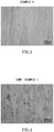
- FIG. 3 is a microscope image of Example 4
- FIG. 4 is a microscope image of Comparative Example 1.
- the length per unit area of a crack observed in the cut surface was calculated as a crack amount.
- Each of the shaped articles of Examples 1 to 6 and Comparative Examples 1 and 2 was cut along a plane perpendicular to the layer stacking direction.
- the pole density in pole figure was measured by EBSD.
- SEM-SU 5000 manufactured by Hitachi, Ltd. and Pegasus Digiview 5 manufactured by EDAX/TSL were used as EBSD devices.
- the measurement of the pole density in pole figure was preceded by a pretreatment in which the cut surface was mechanically polished with waterproof abrasive paper and diamond abrasive grain and then subjected to polish finishing using colloidal silica.
- This pretreatment is intended to ensure the measurement accuracy by reducing the number of points where the measurement is impossible.
- Such a pretreatment is commonly used for Ni-based alloys.
- Kikuchi lines were measured for a 300 ⁇ m ⁇ 300 ⁇ m region of the cut surface with a step size of 3 ⁇ m, and the Kikuchi lines were analyzed by analysis software (OIM Data Collection/OIM Analysis ver.
- the crack amount was significantly large in the cases where the scan line-to-scan line pitch in the laser beam application to the layers was more than 0.08 mm, namely in Comparative Examples 1 and 2 where the L/D was more than 1.0.
- the crack amount was significantly small in Examples 1 to 6 where the scan line-to-scan line pitch in the laser beam application to the layers was adjusted to allow the L/D to fall within the range of 0.3 to 0.9 (namely, the range of 0.2 to 1.0).
Landscapes
- Engineering & Computer Science (AREA)
- Chemical & Material Sciences (AREA)
- Materials Engineering (AREA)
- Manufacturing & Machinery (AREA)
- Mechanical Engineering (AREA)
- Metallurgy (AREA)
- Physics & Mathematics (AREA)
- Organic Chemistry (AREA)
- Plasma & Fusion (AREA)
- Crystallography & Structural Chemistry (AREA)
- Thermal Sciences (AREA)
- Automation & Control Theory (AREA)
- Powder Metallurgy (AREA)
- Laser Beam Processing (AREA)
- Analysing Materials By The Use Of Radiation (AREA)
- Battery Electrode And Active Subsutance (AREA)
Abstract
Description
- The present invention relates to a method of producing a shaped article and to a shaped article obtained by the method.
- A method of producing a shaped article by powder bed fusion using a powder of a Ni-based alloy is conventionally known. The shaped article produced by this production method and made of the Ni-based alloy is used as a high-temperature part such as that of a gas turbine engine.
- In some cases, a gamma prime precipitation strengthening-type Ni-based alloy is used as the Ni-based alloy constituting the powder. The gamma prime precipitation strengthening-type Ni-based alloy is a Ni-based alloy having a composition prepared such that heat treatment of the shaped article produced leads to precipitation of a gamma prime (Ni3(Al,Ti)) phase for strength enhancement.
- It is known that a Ni-based alloy containing Al and Ti is likely to suffer from cracks during welding if the sum of the Al content multiplied by 2 and the Ti content (2Al + Ti) is 6% or more. In powder bed fusion, for example, microcracks having lengths ranging from several micrometers to more than several hundreds of micrometers may be formed in the shaped article produced.
- As for a technique for preventing the occurrence of cracks in a gamma prime precipitation strengthening-type Ni-based alloy during welding, for example,
Patent Literature 1 describes limiting each of the Si content and the Zr content to less than 0.03% in percent by mass. - PTL 1:
Japanese Laid-Open Patent Application Publication (Translation of PCT Application) No. 2017-508877 - However, it is desired to prevent the occurrence of cracks in a gamma prime precipitation strengthening-type Ni-based alloy during welding, in particular to reduce the formation of cracks in a shaped article produced by powder bed fusion, irrespective of whether the Si and Zr contents in the Ni-based alloy are limited.
- It is therefore an object of the present invention to provide: a shaped article production method capable of reducing the formation of cracks in a shaped article produced by powder bed fusion using a powder of a gamma prime precipitation strengthening-type Ni-based alloy; and a shaped article obtained by the shaped article production method.
- As a result of intensive studies with the goal of solving the above problem, the present inventors have found that in powder bed fusion where a laser beam is applied to a layer of a powder along scan lines parallel to one another, a value obtained by dividing the pitch between the scan lines by the laser spot diameter is correlated with the formation of cracks in the shaped article. The present invention has been made based on this finding.
- That is, a shaped article production method of the present invention is a method of producing a shaped article by powder bed fusion using a powder of a gamma prime precipitation strengthening-type Ni-based alloy, wherein the Ni-based alloy contains, in percent by mass, 10 to 16% Cr, 4.5 to 7.5% Al, 2.8 to 6.2% Mo, 0.8 to 4% Nb + Ta, 0.01 to 2% Ti, 0.01 to 0.3% Zr, and 0.01 to 0.3% C, and in applying a laser beam to a layer of the powder along scan lines parallel to one another, a value obtained by dividing a pitch between the scan lines by a laser spot diameter is in the range of 0.2 to 1.0.
- With the above features, the formation of cracks in the shaped article can be reduced.
- A shaped article of the present invention is a shaped article made of a Ni-based alloy, the shaped article including a dendritic crystal structure, wherein the Ni-based alloy contains, in percent by mass, 10 to 16% Cr, 4.5 to 7.5% Al, 2.8 to 6.2% Mo, 0.8 to 4% Nb + Ta, 0.01 to 2% Ti, 0.01 to 0.3% Zr, and 0.01 to 0.3% C, a spacing between branches of a primary dendritic crystal of the dendritic crystal structure is less than 3 µm, and a pole density in pole figure, as measured by EBSD (electron backscatter diffraction), has a maximum of 6 or more.
- The "pole density in pole figure" refers to a parameter determined by using as a reference the state where all crystal orientations appear at a uniform density (this state corresponds to a completely randomly oriented structure) and by calculating the factor by which the frequency of appearance of each crystal orientation in a measurement surface is multiplied relative to the frequency of appearance of the crystal orientation in the reference state. The pole density is calculated as MUD (multiples of a uniform density) by analysis using software attached to the EBSD device. A higher value of the MUD indicates that the crystals in the measurement surface are oriented more unevenly in a particular crystal plane.
- Known examples of methods for producing a cast article with a high MUD value by casting include unidirectional solidification casting and single-crystal casting. However, in cast articles produced by these casting methods, the spacing between the branches of the primary dendritic crystal of the dendritic crystal structure is as large as more than about 40 µm. In contrast, in a shaped article produced by powder bed fusion using a laser beam as a heat source, the spacing between the branches of the primary dendritic crystal of the dendritic crystal structure is as small as less than 3 µm. Additionally, when, in the powder bed fusion, the value obtained by dividing the pitch between the scan lines by the laser spot diameter is in the range of 0.2 to 1.0 as described above, the maximum of the pole density in pole figure (i.e., the MUD) as measured by EBSD is 6 or more. Therefore, a shaped article having the above features is a shaped article with few cracks.
- The present invention makes it possible to reduce the formation of cracks in a shaped article produced by powder bed fusion using a powder of a gamma prime precipitation strengthening-type Ni-based alloy.
-
-
FIG. 1 illustrates a method of producing a shaped article by powder bed fusion. -
FIG. 2 is a graph showing the maximum of the MUD and the crack amount for Examples 1 to 6 and Comparative Examples 1 and 2. -
FIG. 3 is a microscope image of Example 4. -
FIG. 4 is a microscope image of Comparative Example 1. - A shaped article production method according to one embodiment of the present invention is a method of producing a shaped article by powder bed fusion using a powder of a gamma prime precipitation strengthening-type Ni-based alloy. In the present embodiment, the heat source used in the powder bed fusion to melt the powder is a laser beam, although the heat source may be an electron beam in some cases.
- In the powder bed fusion, as shown in
FIG. 1 , alayer 3 of the powder is formed on aplatform 1, and a laser beam is applied to thelayer 3 alongscan lines 4 parallel to one another. The laser beam applied is focused in the vicinity of the surface of thelayer 3. The location, shape, and length of eachscan line 4 are determined depending on the cross-sectional shape of the shaped article to be produced. For example, thescan lines 4 may be straight or curved. -
FIG. 1 illustrates an example of production of a quadrangular prism-shaped article. InFIG. 1 , the laser scan direction is opposite between theadjacent scan lines 4. However, the laser scan direction may be the same for all thescan lines 4. - The application of a laser beam to the
layer 3 results in melting and solidification of a part or the whole of thelayer 3. After that, theplatform 1 is lowered by a distance corresponding to the thickness of thelayer 3, and a new layer (hereinafter referred to as "top layer") 3 of the powder is formed on the previously formed layer (hereinafter referred to as "previous layer") 3. A laser beam is then applied to thetop layer 3 along theparallel scan lines 4. The configuration made up of theprevious layer 3 and thetop layer 3 formed on theprevious layer 3 is abed 2, which includes the already-shaped portion and the unmelted powder. - The directions of the
scan lines 4 may be the same or different between thetop layer 3 andprevious layer 3. In the case where the directions of thescan lines 4 are different between thetop layer 3 andprevious layer 3, the angle of thescan lines 4 of thetop layer 3 with respect to thescan lines 4 of the previous layer 3 (the angle will be referred to as "scan rotation angle" hereinafter) can be determined as appropriate. For example, inFIG. 1 , the scan rotation angle is 90 degrees. - The above process is repeated, and finally the unmelted powder is removed from the
bed 2. In this manner, the shaped article is produced. In such a shaped article, the spacing between the branches of the primary dendritic crystal of the dendritic crystal structure is as small as less than 3 µm. - The particle size distribution of the powder used in the powder bed fusion ranges, for example, from 10 to 60 µm and desirably ranges from 10 to 45 µm. The thickness of the
layers 3 is, for example, equal to or greater than the median value of the particle size distribution of the powder and equal to or smaller than three times the median value of the particle size distribution of the powder. - The Ni-based alloy constituting the powder contains, in percent by mass (the same applies hereinafter), 10 to 16% Cr, 4.5 to 7.5% Al, 2.8 to 6.2% Mo, 0.8 to 4% Nb + Ta, 0.01 to 2% Ti, 0.01 to 0.3% Zr, and 0.01 to 0.3% C as essential components other than Ni. The Ni-based alloy may contain 0.001 to 0.03% B as an essential component. Examples of such a Ni-based alloy include IN 713C ("IN" is an abbreviation of Inconel™; the same applies hereinafter) and IN 713LC. As for Nb and Ta, the Ni-based alloy may be devoid of either Nb or Ta.
- The more desired contents of the essential components are as follows: 11 to 14% Cr, 5.5 to 6.5% Al, 3.8 to 5.2% Mo, 1.65 to 2.65% Nb + Ta, 0.5 to 1.0% Ti, 0.05 to 0.15% Zr, and 0.02 to 0.2% C.
- The Ni-based alloy may contain at least one of less than 1% Co, less than 0.5% Cu, less than 0.5% Fe, and less than 0.5% Si as an optional component. The rest of the Ni-based alloy, namely the portion other than the components mentioned above, is constituted by Ni and inevitable impurities.
- In the present embodiment, in applying a laser beam to each
layer 3, a value (L/D) obtained by dividing a pitch L between thescan lines 4 by a laser spot diameter D is in the range of 0.2 to 1.0. The laser spot diameter D refers to a beam diameter at a point at which the intensity of the laser beam falls down to 1/e2 of the peak value (i.e., the intensity of the laser beam is about 13.5% of the peak value). Some powder bed fusion devices employing lasers permit the user to set the laser spot diameter, and others do not. - The laser spot diameter D is, for example, from 0.02 to 0.20 mm and desirably from 0.05 to 0.15 mm. The pitch L between the
scan lines 4 is, for example, from 0.02 to 0.08 mm. Desirably, the L/D is in the range of 0.3 to 0.9. - The laser scan speed is, for example, from 500 to 3000 mm/s, desirably from 600 to 2000 mm/s, and more desirably from 700 to 1500 mm/s. The laser output is, for example, from 100 to 400 W, desirably from 130 to 350 W, and more desirably from 150 to 300 W.
- By virtue of the fact that in applying a laser beam to each
layer 3, the value (L/D) obtained by dividing the pitch L between thescan lines 4 by the laser spot diameter D is in the range of 0.2 to 1.0 as described above, the formation of cracks in the shaped article can be reduced. In the thus-produced shaped article with few cracks, the maximum of the MUD (the pole density in pole figure as measured by EBSD) is 6 or more (and can be 10 or more depending on the conditions). - Hereinafter, the present invention will be described using examples. The present invention is not limited to the examples described below.
- Powder bed fusion using a powder containing alloy components corresponding to those of IN 713C was carried out to produce a shaped article in the shape of a
cube 10 mm on a side. The particle size distribution of the powder ranged from 16 to 45 µm. Analysis of the alloy components of the powder revealed that the contents of components other than Ni were as follows: 12.41% Cr, 5.94% Al, 4.36% Mo, 1.94% Nb, 0.009% Ta, 0.68% Ti, 0.11% Zr, 0.06% C, 0.01% B, 0.18% Co, 0.02% Cu, 0.20% Fe, and 0.03% Si (the content of inevitable impurities is omitted). - The powder bed fusion device used was EOS M290 manufactured by EOS. In this device, the laser spot diameter D is set to 0.08 mm by the manufacturer. In the production of the shaped article, the thickness of layers was 40 µm, and a laser beam was applied to the layers with a scan line-to-scan line pitch of 0.03 mm, a laser scan speed of 1000 mm/s, a laser output of 180 W, and a scan rotation angle of 90 degrees.
- A shaped article was produced in the same manner as in Example 1, except that the scan line-to-scan line pitch in the laser beam application to the layers was 0.04 mm.
- A shaped article was produced in the same manner as in Example 1, except that the scan line-to-scan line pitch in the laser beam application to the layers was 0.05 mm.
- A shaped article was produced in the same manner as in Example 1, except that the scan line-to-scan line pitch in the laser beam application to the layers was 0.06 mm.
- A shaped article was produced in the same manner as in Example 4, except that the scan rotation angle was 67 degrees.
- A shaped article was produced in the same manner as in Example 1, except that the scan line-to-scan line pitch in the laser beam application to the layers was 0.07 mm.
- A shaped article was produced in the same manner as in Example 1, except that in the laser beam application to the layers, the scan line-to-scan line pitch was 0.09 mm, the laser scan speed was 1250 mm/s, and the laser output was 270 W.
- A shaped article was produced in the same manner as in Example 1, except that in the laser beam application to the layers, the scan line-to-scan line pitch was 0.11 mm, the laser scan speed was 960 mm/s, the laser output was 285 W, and the scan rotation angle was 67 degrees.
- The conditions of the production of the shaped articles of Examples 1 to 6 and Comparative Examples 1 and 2 are shown in Table 1. Table 1 further shows the value (L/D) of the scan line-to-scan line pitch L divided by the laser spot diameter D.
[Table 1] Scan line-to-scan line pitch L (mm) L/D Laser scan speed (mm/s) Laser output (W) Scan rotation angle (degrees) Example 1 0.03 0.375 1000 180 90 Example 2 0.04 0.5 1000 180 90 Example 3 0.05 0.625 1000 180 90 Example 4 0.06 0.75 1000 180 90 Example 5 0.06 0.75 1000 180 67 Example 6 0.07 0.875 1000 180 90 Comparative Example 1 0.09 1.125 1250 270 90 Comparative Example 2 0.11 1.375 960 285 67 - Each of the shaped articles of Examples 1 to 6 and Comparative Examples 1 and 2 was cut along a plane parallel to the layer stacking direction (the upward/downward direction in
FIG. 1 ), and a microscope image of the cut surface was captured.FIG. 3 is a microscope image of Example 4, andFIG. 4 is a microscope image of Comparative Example 1. In each of Examples 1 to 6 and Comparative Examples 1 and 2, the length per unit area of a crack observed in the cut surface was calculated as a crack amount. - Each of the shaped articles of Examples 1 to 6 and Comparative Examples 1 and 2 was cut along a plane perpendicular to the layer stacking direction. For the cut surface, the pole density in pole figure was measured by EBSD. In this measurement, SEM-SU 5000 manufactured by Hitachi, Ltd. and
Pegasus Digiview 5 manufactured by EDAX/TSL were used as EBSD devices. - More specifically, the measurement of the pole density in pole figure was preceded by a pretreatment in which the cut surface was mechanically polished with waterproof abrasive paper and diamond abrasive grain and then subjected to polish finishing using colloidal silica. This pretreatment is intended to ensure the measurement accuracy by reducing the number of points where the measurement is impossible. Such a pretreatment is commonly used for Ni-based alloys. After the pretreatment, Kikuchi lines were measured for a 300 µm × 300 µm region of the cut surface with a step size of 3 µm, and the Kikuchi lines were analyzed by analysis software (OIM Data Collection/OIM Analysis ver. 8, manufactured by EDAX/TSL) to give a {100} pole figure as a projection of the {100} pole. The MUD was calculated based on the pole figure. The calculation of the MUD was carried out using a spherical harmonics method, in which the order of expansion was 16 and the half-value width was 5 degrees.
- The values of the maximum of the MUD and the values of the crack amount in Examples 1 to 6 and Comparative Examples 1 and 2 are shown in Table 2. The values of the maximum of the MUD and the values of the crack amount in Examples 1 to 6 and Comparative Examples 1 and 2 are shown also by the graph in
FIG. 2 .[Table 2] Maximum of MUD Crack amount (mm/mm2) Example 1 12.9 0.20 Example 2 15.7 0.18 Example 3 10.0 0.25 Example 4 11.0 0.08 Example 5 11.3 0.11 Example 6 10.0 0.24 Comparative Example 1 5.1 0.64 Comparative Example 2 4.5 0.95 - As is evident from Table 1 and
FIG. 2 , the crack amount was significantly large in the cases where the scan line-to-scan line pitch in the laser beam application to the layers was more than 0.08 mm, namely in Comparative Examples 1 and 2 where the L/D was more than 1.0. In contrast, the crack amount was significantly small in Examples 1 to 6 where the scan line-to-scan line pitch in the laser beam application to the layers was adjusted to allow the L/D to fall within the range of 0.3 to 0.9 (namely, the range of 0.2 to 1.0). - In Comparative Examples 1 and 2, the maximum of the MUD was less than 6. In contrast, in Examples 1 to 6, the maximum of the MUD was 10 or more (namely, 6 or more). Therefore, a shaped article in which the maximum of the MUD is 6 or more is a shaped article with few cracks.
-
- 1
- platform
- 2
- bed
- 3
- layer
- 4
- scan line
Claims (2)
- A method of producing a shaped article by powder bed fusion using a powder of a gamma prime precipitation strengthening-type Ni-based alloy, whereinthe Ni-based alloy contains, in percent by mass, 10 to 16% Cr, 4.5 to 7.5% Al, 2.8 to 6.2% Mo, 0.8 to 4% Nb + Ta, 0.01 to 2% Ti, 0.01 to 0.3% Zr, and 0.01 to 0.3% C, andin applying a laser beam to a layer of the powder along scan lines parallel to one another, a value obtained by dividing a pitch between the scan lines by a laser spot diameter is in the range of 0.2 to 1.0.
- A shaped article made of a Ni-based alloy, the shaped article including a dendritic crystal structure, whereinthe Ni-based alloy contains, in percent by mass, 10 to 16% Cr, 4.5 to 7.5% Al, 2.8 to 6.2% Mo, 0.8 to 4% Nb + Ta, 0.01 to 2% Ti, 0.01 to 0.3% Zr, and 0.01 to 0.3% C,a spacing between branches of a primary dendritic crystal of the dendritic crystal structure is less than 3 µm, anda pole density in pole figure, as measured by EBSD, has a maximum of 6 or more.
Applications Claiming Priority (2)
| Application Number | Priority Date | Filing Date | Title |
|---|---|---|---|
| JP2019044898A JP7141966B2 (en) | 2019-03-12 | 2019-03-12 | Modeled body manufacturing method and modeled body |
| PCT/JP2020/010064 WO2020184518A1 (en) | 2019-03-12 | 2020-03-09 | Shaped body manufacturing method and shaped body |
Publications (2)
| Publication Number | Publication Date |
|---|---|
| EP3939721A1 true EP3939721A1 (en) | 2022-01-19 |
| EP3939721A4 EP3939721A4 (en) | 2023-06-28 |
Family
ID=72427604
Family Applications (1)
| Application Number | Title | Priority Date | Filing Date |
|---|---|---|---|
| EP20769644.4A Pending EP3939721A4 (en) | 2019-03-12 | 2020-03-09 | Shaped body manufacturing method and shaped body |
Country Status (6)
| Country | Link |
|---|---|
| US (1) | US20220145429A1 (en) |
| EP (1) | EP3939721A4 (en) |
| JP (1) | JP7141966B2 (en) |
| CN (1) | CN113490561A (en) |
| TW (1) | TWI784246B (en) |
| WO (1) | WO2020184518A1 (en) |
Families Citing this family (7)
| Publication number | Priority date | Publication date | Assignee | Title |
|---|---|---|---|---|
| CN111500898B (en) * | 2020-06-19 | 2021-02-02 | 北京钢研高纳科技股份有限公司 | Nickel-based superalloy, method for producing same, component and use |
| JP7702236B2 (en) * | 2020-09-11 | 2025-07-03 | 川崎重工業株式会社 | FORMED BODY MANUFACTURING METHOD AND FORMED BODY |
| JP7702237B2 (en) * | 2020-09-11 | 2025-07-03 | 川崎重工業株式会社 | Method for manufacturing shaped body, intermediate body and shaped body |
| CN116829281B (en) * | 2021-02-05 | 2026-05-05 | 株式会社博迈立铖 | Ni-based alloy powder for laminated molding, laminated moldings and their manufacturing methods |
| FR3128651B1 (en) * | 2021-11-04 | 2024-02-16 | Safran | PROCESS FOR SELECTIVE POWDER BED MELTING OF AN ALLOY WITH DIRECTED SOLIDIFICATION |
| FR3129857B1 (en) * | 2021-12-07 | 2024-12-06 | Safran Aircraft Engines | Metal powder for powder bed additive manufacturing process |
| FR3129858B1 (en) * | 2021-12-07 | 2024-01-05 | Safran Aircraft Engines | Metal powder for a powder bed additive manufacturing process |
Family Cites Families (9)
| Publication number | Priority date | Publication date | Assignee | Title |
|---|---|---|---|---|
| CH705662A1 (en) * | 2011-11-04 | 2013-05-15 | Alstom Technology Ltd | Process for producing articles of a solidified by gamma-prime nickel-base superalloy excretion by selective laser melting (SLM). |
| EP2886225B1 (en) * | 2013-12-23 | 2017-06-07 | Ansaldo Energia IP UK Limited | Gamma prime precipitation strengthened nickel-base superalloy for use in powder based additive manufacturing process |
| CN104745887A (en) * | 2015-03-17 | 2015-07-01 | 江苏思莱姆智能科技有限公司 | Nano ceramic particle reinforced nickel-based superalloy composite material and laser 3D printing forming method thereof |
| US10378087B2 (en) * | 2015-12-09 | 2019-08-13 | General Electric Company | Nickel base super alloys and methods of making the same |
| CN105728725B (en) * | 2016-03-31 | 2018-02-09 | 南京航空航天大学 | The method that 3D printing prepares multielement transition interface collaboration enhancing nickel-base composite material |
| JP2018058111A (en) * | 2016-09-28 | 2018-04-12 | 日立金属株式会社 | Melting processing wire and manufacturing method thereof |
| WO2019012559A1 (en) * | 2017-07-12 | 2019-01-17 | Bharat Forge Limited | An additive manufacturing process for combustion chamber |
| GB2565063B (en) * | 2017-07-28 | 2020-05-27 | Oxmet Tech Limited | A nickel-based alloy |
| CN108941560B (en) * | 2018-07-27 | 2019-06-11 | 中南大学 | A method of it eliminating Rene104 nickel base superalloy laser gain material and manufactures crackle |
-
2019
- 2019-03-12 JP JP2019044898A patent/JP7141966B2/en active Active
-
2020
- 2020-03-09 US US17/438,681 patent/US20220145429A1/en not_active Abandoned
- 2020-03-09 EP EP20769644.4A patent/EP3939721A4/en active Pending
- 2020-03-09 CN CN202080016158.1A patent/CN113490561A/en active Pending
- 2020-03-09 WO PCT/JP2020/010064 patent/WO2020184518A1/en not_active Ceased
- 2020-03-11 TW TW109108005A patent/TWI784246B/en active
Also Published As
| Publication number | Publication date |
|---|---|
| US20220145429A1 (en) | 2022-05-12 |
| CN113490561A (en) | 2021-10-08 |
| TWI784246B (en) | 2022-11-21 |
| TW202045741A (en) | 2020-12-16 |
| WO2020184518A1 (en) | 2020-09-17 |
| JP7141966B2 (en) | 2022-09-26 |
| EP3939721A4 (en) | 2023-06-28 |
| JP2020147781A (en) | 2020-09-17 |
Similar Documents
| Publication | Publication Date | Title |
|---|---|---|
| US20220145429A1 (en) | Shaped article production method and shaped article | |
| KR102855094B1 (en) | Method for manufacturing aluminum alloy parts | |
| CN100503843C (en) | Hard metallic materials, hard metallic coatings, methods of processing metallic materials and methods of producing metallic coatings | |
| EP3939720A1 (en) | Method for manufacturing shaped article, and intermediate and shaped article | |
| EP4212268A1 (en) | Shaped article manufacturing method, intermediate, and shaped article | |
| Oh et al. | Effect of in-situ heat treatments on deposition characteristics and mechanical properties for repairs using laser melting deposition | |
| CN113020585B (en) | A low melting point multicomponent alloy additive for laser additive manufacturing of aluminum alloys | |
| JP7702236B2 (en) | FORMED BODY MANUFACTURING METHOD AND FORMED BODY | |
| CN114340820B (en) | Method for manufacturing alloy component, and alloy component | |
| US20250179615A1 (en) | Ni-based alloy powder for additive manufacturing, additively manufactured product, and method for manufacturing additively manufactured product | |
| Shen et al. | Microstructure and mechanical properties of selective laser melting of hydrogen embrittlement resistance stainless steel HR-2 | |
| DE102017009948A1 (en) | Process for the repair of monocrystalline materials | |
| JP2017115224A (en) | Aluminum alloy hard foil | |
| EP4289982B1 (en) | Ni-based alloy powder for additive manufacturing, additive manufactured component, and additive manufacturing method thereof | |
| EP4567144A1 (en) | Fe-cr-al-based alloy powder for additive manufacturing, fe-cr-al-based alloy member, and method for producing fe-cr-al-based alloy member | |
| CN121752374A (en) | Ni-based alloy powder for additive manufacturing and method for manufacturing Ni-based alloy molded article | |
| TW202513812A (en) | Ni-based alloy shapes | |
| WO2025019505A1 (en) | Additive manufacturing of core-shell structures | |
| CN120394892A (en) | A method for in-situ fabrication of high-performance Ti2AlNb alloy by particle size-controlled laser directed energy deposition | |
| JP2022047833A (en) | Method for heat-treating laminated molding and method for producing low thermal expansion alloy molding |
Legal Events
| Date | Code | Title | Description |
|---|---|---|---|
| STAA | Information on the status of an ep patent application or granted ep patent |
Free format text: STATUS: THE INTERNATIONAL PUBLICATION HAS BEEN MADE |
|
| PUAI | Public reference made under article 153(3) epc to a published international application that has entered the european phase |
Free format text: ORIGINAL CODE: 0009012 |
|
| STAA | Information on the status of an ep patent application or granted ep patent |
Free format text: STATUS: REQUEST FOR EXAMINATION WAS MADE |
|
| 17P | Request for examination filed |
Effective date: 20211012 |
|
| AK | Designated contracting states |
Kind code of ref document: A1 Designated state(s): AL AT BE BG CH CY CZ DE DK EE ES FI FR GB GR HR HU IE IS IT LI LT LU LV MC MK MT NL NO PL PT RO RS SE SI SK SM TR |
|
| DAV | Request for validation of the european patent (deleted) | ||
| DAX | Request for extension of the european patent (deleted) | ||
| RAP3 | Party data changed (applicant data changed or rights of an application transferred) |
Owner name: KAWASAKI JUKOGYO KABUSHIKI KAISHA |
|
| RIN1 | Information on inventor provided before grant (corrected) |
Inventor name: IGASHIRA, KENICHIRO Inventor name: NOMURA, YOSHIMICHI Inventor name: OKADA, RYUTARO |
|
| A4 | Supplementary search report drawn up and despatched |
Effective date: 20230531 |
|
| RIC1 | Information provided on ipc code assigned before grant |
Ipc: B22F 5/04 20060101ALN20230524BHEP Ipc: B22F 5/00 20060101ALN20230524BHEP Ipc: C22C 1/04 20060101ALI20230524BHEP Ipc: B33Y 10/00 20150101ALI20230524BHEP Ipc: B33Y 80/00 20150101ALI20230524BHEP Ipc: B22F 10/366 20210101ALI20230524BHEP Ipc: B22F 10/28 20210101ALI20230524BHEP Ipc: C22F 1/10 20060101ALI20230524BHEP Ipc: C22C 19/05 20060101ALI20230524BHEP Ipc: B22F 3/16 20060101ALI20230524BHEP Ipc: B22F 3/105 20060101AFI20230524BHEP |