EP3937745B1 - Spender zur ausgabe von blattprodukten - Google Patents
Spender zur ausgabe von blattprodukten Download PDFInfo
- Publication number
- EP3937745B1 EP3937745B1 EP19711537.1A EP19711537A EP3937745B1 EP 3937745 B1 EP3937745 B1 EP 3937745B1 EP 19711537 A EP19711537 A EP 19711537A EP 3937745 B1 EP3937745 B1 EP 3937745B1
- Authority
- EP
- European Patent Office
- Prior art keywords
- mounting structure
- dispenser
- cabinet
- connection portion
- dispensing
- Prior art date
- Legal status (The legal status is an assumption and is not a legal conclusion. Google has not performed a legal analysis and makes no representation as to the accuracy of the status listed.)
- Active
Links
Images


Classifications
-
- A—HUMAN NECESSITIES
- A47—FURNITURE; DOMESTIC ARTICLES OR APPLIANCES; COFFEE MILLS; SPICE MILLS; SUCTION CLEANERS IN GENERAL
- A47K—SANITARY EQUIPMENT; ACCESSORIES THEREFOR, e.g. TOILET ACCESSORIES
- A47K10/00—Body-drying implements; Toilet paper; Holders therefor
- A47K10/24—Towel dispensers; Toilet paper dispensers
- A47K10/32—Dispensers for paper towels or toilet paper
- A47K10/42—Dispensers for paper towels or toilet paper dispensing from a store of single sheets, e.g. stacked
- A47K10/424—Dispensers for paper towels or toilet paper dispensing from a store of single sheets, e.g. stacked dispensing from the bottom part of the dispenser
-
- A—HUMAN NECESSITIES
- A47—FURNITURE; DOMESTIC ARTICLES OR APPLIANCES; COFFEE MILLS; SPICE MILLS; SUCTION CLEANERS IN GENERAL
- A47B—TABLES; DESKS; OFFICE FURNITURE; CABINETS; DRAWERS; GENERAL DETAILS OF FURNITURE
- A47B81/00—Cabinets or racks specially adapted for other particular purposes, e.g. for storing guns or skis
-
- A—HUMAN NECESSITIES
- A47—FURNITURE; DOMESTIC ARTICLES OR APPLIANCES; COFFEE MILLS; SPICE MILLS; SUCTION CLEANERS IN GENERAL
- A47K—SANITARY EQUIPMENT; ACCESSORIES THEREFOR, e.g. TOILET ACCESSORIES
- A47K10/00—Body-drying implements; Toilet paper; Holders therefor
- A47K10/24—Towel dispensers; Toilet paper dispensers
- A47K10/32—Dispensers for paper towels or toilet paper
- A47K10/34—Dispensers for paper towels or toilet paper dispensing from a web, e.g. with mechanical dispensing means
- A47K10/36—Dispensers for paper towels or toilet paper dispensing from a web, e.g. with mechanical dispensing means with mechanical dispensing, roll switching or cutting devices
-
- A—HUMAN NECESSITIES
- A47—FURNITURE; DOMESTIC ARTICLES OR APPLIANCES; COFFEE MILLS; SPICE MILLS; SUCTION CLEANERS IN GENERAL
- A47K—SANITARY EQUIPMENT; ACCESSORIES THEREFOR, e.g. TOILET ACCESSORIES
- A47K10/00—Body-drying implements; Toilet paper; Holders therefor
- A47K10/24—Towel dispensers; Toilet paper dispensers
- A47K10/32—Dispensers for paper towels or toilet paper
- A47K2010/3233—Details of the housing, e.g. hinges, connection to the wall
-
- A—HUMAN NECESSITIES
- A47—FURNITURE; DOMESTIC ARTICLES OR APPLIANCES; COFFEE MILLS; SPICE MILLS; SUCTION CLEANERS IN GENERAL
- A47K—SANITARY EQUIPMENT; ACCESSORIES THEREFOR, e.g. TOILET ACCESSORIES
- A47K2201/00—Details of connections of bathroom accessories, e.g. fixing soap or towel holder to a wall
- A47K2201/02—Connections to a wall mounted support
Definitions
- the present disclosure relates to a dispenser for dispensing sheet products, particularly sanitary paper sheet products such as hand towels, paper napkins, facials, toilet paper, or other wiping products in sheet form. More particular, the disclosure relates to a dispensing mechanism to be mounted in an existing cabinet, preferably an existing recessed cabinet, for retrofitting. Furthermore, the present disclosure relates to a method for mounting a dispensing mechanism.
- Sheet products are generally stacked or rolled up and accommodated in a cabinet of a dispenser. Dispensing of sheet products through a dispensing opening formed in the dispenser cabinet is enabled by a dispensing mechanism allowing a user to grasp a leading sheet product, for example a protruding part of a leading sheet product protruding from the dispensing opening. Examples of different dispensing mechanisms are disclosed in US 3,432,217 A , WO 2014/065733 A1 , and WO 2013/007302 A2 . In order to improve the dispensing process and make dispensers less prone to malfunction, the dispensing mechanisms for dispensing the sheet products have become more sophisticated over the past decades.
- US 2 932 426 A discloses an improved dispensing device for paper towels.
- the dispensing device is particularly adapted for use in dispensing C-fold paper towels and provides simple lever-operated mechanism for engaging the forward flap of the bottommost C-fold towel of a stack in a cabinet to project the flap a sufficient distance through a dispensing opening so that it can be grasped and pulled outwardly.
- KR 101 535 040 B1 discloses a hand towel dispensing apparatus.
- the hand towel dispensing apparatus mounted in a towel accepting part of a hand towel dispenser is joined to a towel dispensing groove formed in the towel accepting part to be detached, wherein a V-shaped slope is formed in the longitudinal direction of a side where the towel dispensing groove is formed and an outlet connected to the towel dispensing groove is formed at the lateral center of the slope.
- the hand towel dispensing apparatus is easy to install and saves costs by preventing the waste of hand towels with the mount of the hand towel dispensing apparatus without removing an existing hand towel dispenser.
- US 2011/036855 A1 discloses a paper towel dispenser assembly including a support frame that receives a continuous length of pleated paper toweling.
- the paper towel dispenser assembly further including a sensor that actuates dispense of an end of the continuous length of pleated paper toweling and a cutter that cuts a discrete towel from the end of the continuous length of pleated paper toweling.
- US 6 003 723 A discloses dispenser apparatus for stacked single-fold towel sheets has a rear wall, side walls, and front and rear funnel walls extending to a funnel height between bottom portions of the side walls on opposite sides of a feed slot; and a pair of shelf members projecting downwardly and inwardly from respective ones of the side walls, each shelf member having a shelf width perpendicular to the rear wall being approximately 45 percent of a housing depth between upper extremities of the funnel walls, inward extremities of the shelf members, the inward extremities being spaced above the feed slot within the funnel height and being spaced apart by a distance of not greater than approximately 90 percent of the stack width for partially supporting the sheets.
- Each shelf member has an upwardly and inwardly facing panel surface that forms a side angle of approximately 45 degrees with the side wall.
- a perimeter contour of each shelf member has a plan radius of approximately 0.5 inch at the inward extremity, diverging to the shelf width from the plan radius at a taper angle of approximately 90 degrees, the perimeter contour also having an edge profile of smooth curvature including a shelf lip radius of approximately 0.15 inch extending outwardly and downwardly from the panel surface.
- US 5 950 863 A discloses an insert device for a sheet dispenser having a housing for receiving a stack of folded sheets, a bottom opening of the housing being formed as a rounded elongate slot having an enlarged center portion, includes a rear panel portion; an upwardly and forwardly sloping front ramp portion, a pair of side panel portions connecting the front ramp potion to the rear panel portion; and a ledge portion extending forwardly from the panel portion toward the ramp portion. Also disclosed is a method for bottom loading of the insert device (with stacked sheets therein) into a dispenser having door members defining a bottom opening thereof.
- dispensers having cabinets which are partially or completely recessed within a wall.
- many of these recessed cabinet dispensers like the one disclosed in US 3,432,217 A , are based on older dispensing mechanisms which have disadvantages compared to new technologies. It is therefore desirable to replace those dispensers with dispensers using newer dispensing mechanisms. Since recessed cabinets form part of a solid wall of a building, it is however expensive and time-consuming to replace existing recessed dispensers with new recessed dispensers using the latest technologies.
- a set for mounting a dispensing mechanism for dispensing sheet products within an existing dispenser cabinet that comprises a bottom wall having a dispensing opening, the set having the features defined in claim 1, is disclosed.
- the existing dispenser cabinet may be partially or completely recessed within a wall.
- the set comprises the dispensing mechanism, wherein the dispensing mechanism comprises a lower portion, the lower portion comprising a first connection portion (which may also be referred to as "connecting portion").
- the set comprises a mounting structure comprising a second connection portion (which may also be referred to as "connection portion") to which the first connection portion of the lower portion is attachable to support the dispensing mechanism.
- the mounting structure is configured to be fastened to the bottom wall.
- the mounting structure supports the dispensing mechanism and is configured to be fastened to the bottom wall of the cabinet, it is possible to mount the dispensing mechanism within the cabinet in a simple way.
- the dispensing mechanism is fastened to the rear wall of the cabinet. This is time-consuming and associated with difficulties because proper fastening positions at the rear wall of the cabinet have to be determined beforehand in order to ensure that the dispensing mechanism is located at the proper height.
- the term "cabinet” refers to an existing cabinet.
- the terms "dispensing mechanism” and “dispenser” of the present disclosure refer to devices to be mounted within such a cabinet.
- the dispensing mechanism of the set according to the disclosure may be of the kind of or based on a dispensing mechanism in which sheet products are dispensed from the top of the stack, such as those disclosed in WO 2013/007302 A2 or WO 2014/065733 A1 , the content of which is herewith incorporated in its entirety by reference.
- individual sheet products may be connected by lines of weakness (perforations) to form a web.
- Such a web may be guided within the dispensing mechanism with one or more than one guiding element, such as a roll or the like, in order to properly guide the web along a specific path to the dispensing opening of the cabinet.
- a web may also be provided without lines of weakness to form a homogeneous web from which individual sheet products may be separated by means of a cutting edge.
- other kinds of dispensing mechanisms are conceivable, such as dispensing mechanisms in which the sheet products are dispensed from the bottom of the stack.
- sheet products may be individually provided.
- the dispensing mechanism may also be a dispensing mechanism in which the sheet product is not provided in a stack, but rolled up on a roll or more than one roll.
- the dispensing mechanism may comprise a roll or more than one roll and the sheet product may be a continuous web rolled up on the roll.
- the cabinets within which the dispensing mechanism can be mounted, may at least be partially recessed within a wall and may generally comprise a first side wall, a second side wall opposing the first side wall and a rear wall extending between the first side wall and the second side wall.
- existing recessed cabinets may be provided with a door for closing the recessed cabinet in order to protect the dispensing mechanism and improve the appearance of the dispenser.
- the door may be flush with the wall within which the recessed cabinet is arranged.
- the recessed cabinet may be completely recessed within a wall.
- the recessed cabinet may also be only partially recessed within a wall while also protruding to some extent from the wall.
- the cabinet comprises a bottom wall which has a dispensing opening.
- the bottom wall may be firmly attached to or integrally formed with the cabinet.
- various kinds and shapes of the bottom wall of the dispenser cabinets may exist.
- the bottom wall may generally comprise a slanted or curved surface, as the one shown in US 3,432,217 A , which may extend in an upward direction from the rear wall of the cabinet.
- the set and the dispenser according to the disclosure are exemplarily described in connection with an existing recessed cabinet, the set and the dispenser according to the disclosure may also be applied to a cabinet which is not recessed within a wall, but mounted to a wall or freestanding.
- the dispensing mechanism of the set according to the disclosure comprises a lower portion.
- the lower portion may generally be understood as a portion of the dispensing mechanism being located at a lower position of the dispensing mechanism as seen in the up-down direction of the cabinet.
- the dispensing mechanism may comprise a frame which is configured to be mounted in the cabinet.
- the lower portion may be a lower portion of the frame.
- the dispensing mechanism may also comprise more than one lower portion.
- the frame of the dispensing mechanism may comprise a left side wall and a right side wall, wherein each of the left side wall and the right side wall comprises a lower portion.
- the lower portion comprises a first connection portion.
- the first connection portion of the lower portion may be located at a lower end of the lower portion.
- the first connection portion may be located at the lower end of the frame of the dispensing mechanism.
- the mounting structure of the set may be understood as the structure with which the dispensing mechanism is mounted within the recessed cabinet.
- the mounting structure comprises a second connection portion to which the first connection portion of the lower portion of the dispensing mechanism is attachable to support the dispensing mechanism.
- the second connection portion of the mounting structure may be specifically designed in order to provide proper connection between the second connection portion and the first connection portion of the dispensing mechanism of the set.
- the dispensing mechanism may comprise two lower portions, each of the two lower portions having a first connection portion.
- the mounting structure comprises two second connection portions to which the first connection portions of the lower portions are respectively attachable.
- the first connection portion may be inseparably attachable to the second connection portion.
- the first connection portion may be detachably attachable to the second connection portion.
- the mounting structure supports the dispensing mechanism when the dispensing mechanism is attached to the mounting structure. This may imply that the mounting structure has sufficient rigidity in order to be able to support the dispensing mechanism. Moreover, the mounting structure may be able to support the dispensing mechanism without the provision of further or other supporting means.
- the mounting structure is configured to be fastened to the bottom wall.
- fastenable respectively, “configured to be fastened” may imply that the mounting structure is fastened to the bottom wall such that the mounting structure and, in turn, the dispensing mechanism is firmly mounted in the recessed cabinet.
- the mounting structure may be located at an upper side of the bottom wall, as seen in the up-down direction of the cabinet, when being fastened to the bottom wall.
- the bottom wall of the recessed cabinet may differ in shape. Therefore, the mounting structure may generally be sized in order to properly fit to various shapes of the bottom wall, without covering the dispensing opening defined in the bottom wall in order not to hinder the sheet products from passing through the dispensing opening.
- the mounting structure may be inseparably fastened to the bottom wall.
- the mounting structure may be detachably fastenable to the bottom wall, for example, to also mount the mounting structure to another recessed cabinet.
- the first connection portion may be non-pivotably attachable to the second connection portion.
- first connection portion according to the invention is pivotably attachable to the second connection portion.
- pivotably attachable may mean that the dispensing mechanism can be pivoted about the mounting structure about an axis of rotation.
- each part of the dispensing mechanism may be pivotably movable by the same angle of rotation about the axis of rotation.
- only specific parts of the dispensing mechanism may be pivotably movable.
- Pivotable attachment of the first connection portion to the second connection portion may be realized by means of hinges, a pin engaged with a hole, or the like.
- the cabinet may comprise a top wall opposing the bottom wall, wherein the space in the up-down direction of the cabinet is defined by the space between the bottom wall and the top wall.
- the mounting structure is fastenable to the bottom wall.
- the dispensing mechanism would be mounted to the recessed cabinet by arranging the dispensing mechanism in an upright position above the mounting structure within the recessed cabinet and subsequently lowering the dispensing mechanism in a downward direction in order to attach the first connection portion to the second connection portion.
- this lowering movement requires a certain space in the up-down direction within the recessed cabinet. Since, according to the disclosure, the first connection portion is pivotably attachable to the second connection portion, attaching the dispensing mechanism to the mounting structure does not require such lowering movement.
- the dispensing mechanism may be attached to the mounting structure by attaching the first connection portion to the second connection portion with the dispensing mechanism being in a slanted position with respect to the rear wall of the cabinet and subsequently pivoting the dispensing mechanism into the cabinet.
- the second connection portion may comprise a substantially cylindrical shape, wherein the first connection portion is substantially U-shaped and engageable with the second connection portion.
- substantially cylindrical may mean that not the entire shape of the second connection portion is cylindrical.
- only parts of the second connection portion comprise a cylindrical shape or that a cross section of the second connection portion or of parts thereof does not form a full circle.
- substantially U-shaped may mean that not the entire first connection portion is U-shaped, but only parts thereof.
- a cross section of the first connection portion or of parts thereof may not form a perfect U-shape but rather an open-circle shape or the like.
- the dispensing mechanism may further comprise an upper portion, wherein the upper portion is attachable to the dispenser cabinet.
- the upper portion of the dispensing mechanism may be an upper portion of the frame of the dispensing mechanism. However, also other parts of the dispensing mechanism located at an upper position of the dispensing mechanism in the up-down direction of the cabinet may be the upper portion.
- the upper portion may be attachable to the dispenser cabinet by means of adhesive tape, screws, hooks, hook and loop fastener, or the like. With this configuration, it is possible to additionally secure the dispensing mechanism within the recessed cabinet, i.e. in addition to supporting the dispensing mechanism by means of the mounting structure.
- the first connection portion of the lower portion of the dispensing mechanism may be pivotably attached to the second connection portion of the mounting structure. In this case, using adhesive tape and/or hook and loop fastener, the upper portion of the dispensing mechanism may be attached to the dispenser cabinet upon pivoting the dispensing mechanism into the cabinet toward the rear wall thereof.
- the upper portion may be attachable to the rear wall of the recessed cabinet.
- the upper portion may be attachable to the cabinet via additional attaching devices arranged between the dispensing mechanism and the wall of the cabinet.
- the upper portion may be directly attachable to the dispenser cabinet, thereby reducing parts of the set for mounting a dispensing mechanism according to the disclosure.
- the first connection portion may be snappable onto or into the second connection portion.
- the first connection portion may be made of a slightly flexible and elastic material, such as plastic or the like, and the U-shape or open-circle shape of the first connection portion may have a smaller diameter than the respective cylindrical shape of the second connection portion.
- the first connection portion may be attached to the second connection portion by pressing the first connection portion onto the second connection portion, thereby slightly pressing apart respective parts of the first connection portion forming the U-shape so as to increase the diameter of the U-shape and to allow connection to the second connection portion. Due to the flexible and elastic material of the first connection portion, said respective parts of the first connection portion forming the U-shape may be urged to return to their original position upon connection to the second connection portion, thereby snapping onto the second connection portion and completing connection.
- the first connection portion may also be snappable into the second connection portion.
- the first connection portion may comprise a protruding part and the second connection portion may comprise a hole, wherein the protruding part of the first connection portion is engageable with the hole of the second connection portion.
- Examples of such kind of connection may be a ball joint connection or a snap connection with spring-loaded hooks.
- the mounting structure may comprise a fastening member configured to be fastened to an edge of the dispensing opening.
- the fastening member may be connected to the mounting structure.
- the fastening member may also be integrally formed with the mounting structure. It is also conceivable, that the fastening member is a separate element which is connectable or attachable to the mounting structure.
- the mounting structure may also comprise more than one fastening member.
- the mounting structure may comprise one fastening member, or two fastening members, or three fastening members, or four fastening members, or five fastening members.
- the fastening member may be fastenable to any edge of the dispensing opening, i.e. a front edge, a rear edge, or a side edge as seen with respect to the recessed cabinet.
- the fastening member can encompass the edge of the dispensing opening, thereby more reliably fastening the mounting structure to the bottom wall.
- the fastening member may be configured to be fastened to a rear edge of the dispensing opening.
- the rear edge of the dispensing opening may be the edge which is located closest to the rear wall of the dispenser cabinet.
- continuous dispensing of sheet products from the dispenser is realized by means of the dispensing mechanism ensuring that a protruding part of a leading sheet product protrudes through the dispensing opening and is easily graspable by a user. Since the protruding part covers or obscures the rear edge of the dispensing opening, the protruding part also covers or obscures the fastening member being fastenable to the rear edge of the dispensing opening.
- the fastening member of the mounting structure is configured to be fastened to the bottom wall by structurally modifying the bottom wall.
- the fastening member may comprise a screw with which the mounting structure is fastenable to the bottom wall, the screw thereby modifying the structure of the bottom wall by penetrating through the bottom wall.
- the fastening member of the mounting structure may be configured to be fastened to the bottom wall without structurally modifying the bottom wall.
- Structural modification of the bottom wall may comprise forming through holes in the bottom wall, for example in case the fastening member is fastened to the bottom wall by means of screws.
- Structural modification may also comprise modifying the overall shape of the bottom wall, for example by bending of the bottom wall.
- Structural modification may further comprise forming slits or the like in the bottom wall in order to fasten the fastening member to the bottom wall.
- the dispensing mechanism can be mounted in the recessed cabinet in a simple way. Moreover, since the bottom wall is not structurally modified by the fastening member, damage of the bottom wall and/or the recessed cabinet can be prevented.
- the fastening member may be selected from the group consisting of a clip, a clamp, a tape, a hook and loop fastener, and combinations thereof.
- the fastening member may be a clip, a clamp, a tape, or a hook and loop fastener.
- the fastening member may also be configured by a combination of a clip and a clamp or a clip and a tape and so on.
- the tape may be an adhesive tape.
- the clip and the clamp may be composed of several elements.
- the clamp may comprise an eccentric-type quick-release mechanism being actuated by a lever.
- the mounting structure may comprise more than one fastening member.
- more than one of the above elements of the group may be provided.
- one clip, or two clips, or three clips, or four clips, or five clips may be provided.
- the mounting structure can be easily fastened to the bottom wall. This is because no tool is required in order to fasten the elements of the above group to an edge of the dispensing opening. Moreover, since no tool is required, fastening the mounting structure to the bottom wall and, in turn, mounting the dispensing mechanism within the recessed cabinet can be performed more quickly.
- the fastening member may be a clip, wherein the clip may comprise a spring clip having a substantially U-shaped cross section.
- substantially U-shaped may mean that not the entire cross section of the spring clip is U-shaped, but only parts thereof. Moreover, the cross section of the spring clip or of parts thereof may not form a perfect U-shape but also an open-circle shape, a shape comprising corners, or the like.
- the spring clip may comprise two legs being connected or integrally connected to each other so as to form the U-shaped cross section. One leg may engage with the mounting structure and the other leg may engage with the edge of the dispensing opening so as to fasten the mounting structure to the bottom wall of the cabinet.
- the spring clip may be made of metal in order to provide proper spring properties so as to properly fasten the mounting structure to the bottom wall.
- the spring clip may also be made of plastic being flexible and elastic and having similar properties.
- the spring clip may comprise two legs, the two legs may be spaced apart from each other by a certain distance in case the spring clip is in an unloaded state, i.e., when the mounting structure is not fastened to the bottom wall by means of the fastening member.
- the spring clip may be configured such that a loaded state of the spring clip is a state in which the two legs tend to urge towards each other, due to the spring force, if they are further spaced apart from each other compared to the unloaded state.
- the spring clip may be configured such that the spring clip is in the loaded state if one leg engages with the mounting structure and the other leg engages with an edge of the dispensing opening. In this case, the spring force exerted by the spring clip may fasten the mounting structure to the bottom wall of the recessed cabinet.
- the spring clip may also comprise more than two legs.
- the spring clip may comprise three legs, wherein two legs may engage with the mounting structure and one leg may engage with the edge of the dispensing opening so as to fasten the mounting structure to the bottom wall of the cabinet.
- the clip may further comprise a clip body having a substantially U-shaped cross section and encasing the spring clip.
- the clip body may be sized to encase the spring clip.
- the clip body may be slightly larger in size so as to properly encase the spring clip.
- the clip body may be made of plastic. With this configuration, it is possible to improve handling of the clips while fastening the mounting structure to the bottom wall. Moreover, it is possible to provide a more stable configuration of the clip.
- the clip body may comprise grooves or other structures on the outside thereof. These structures may enhance grip between the clip and a user's hand, while fastening the mounting structure to the bottom wall.
- the mounting structure may comprise one or more than one slot opening.
- the slot opening may have a slot length along its longitudinal axis, wherein the clip body may comprise two legs, wherein one of the two legs may penetrate the slot opening.
- the one of the two legs may comprise a protrusion portion which may extend in a direction parallel to the longitudinal axis of the slot opening and which may have a length longer than the slot length.
- the mounting structure may comprise one slot opening or more than one slot opening.
- the mounting structure may comprise two slot openings.
- the mounting structure may also comprise more than two slot openings, for example, three slot openings, four slot openings, or five slot openings.
- the slot opening may be pre-formed in the mounting structure.
- the slot opening may have a longitudinal shape, like a slit, or a groove, or the like. Hence, the slot opening has a slot length along its longitudinal axis.
- the clip body encasing the spring clip comprises two legs.
- the legs are formed integrally, so as to follow the shape of the spring clip.
- One of the two legs of the clip body penetrates the slot opening.
- the one of the two legs penetrating the slot opening may penetrate the slot opening in such a way that the clip may be displaced or moved relative to the mounting structure in a direction along the leg of the clip without the slot opening hindering the movement of the clip.
- the one of the two legs may penetrate the slot opening in such a way that the clip may be displaced to some extent relative to the mounting structure in the up-down direction and/or in the left-right direction of the cabinet when the mounting structure is arranged or placed on the bottom wall of the cabinet.
- the one of the two legs may penetrate the slot opening in such a way that the clip may be rotated to some degrees relative to the mounting structure in any direction, for example about an axis of rotation parallel to the front-rear direction of the cabinet, and/or about an axis of rotation parallel to the left-right direction of the cabinet, and/or about an axis of rotation parallel to the up-down direction of the cabinet, when the mounting structure is arranged or placed on the bottom wall of the cabinet.
- the clip can be optimally oriented with respect to the shape of the rear edge of the dispensing opening of the bottom wall, thereby optimizing fastening of the mounting structure to the bottom wall of the cabinet.
- the one of the two legs which penetrates the slot opening comprises a protrusion portion.
- the protrusion portion may be an extra element connected to the one of the two legs or may be integrally formed with the one of the two legs. Furthermore, the protrusion portion may form an end portion of the one of the two legs.
- the protrusion portion extends in a direction parallel to the longitudinal axis of the slot opening and has a length longer than the slot length, the clip can be prevented from moving out of the slot opening of the mounting structure. This prevents losing the clips when the mounting structure is not fastened to the bottom wall, for example during transport. Moreover, fastening of the mounting structure to the bottom wall of the cabinet can be facilitated because the clips do not have to be separately held by a user.
- the clip body may also comprise more than two legs, for example in cases in which the spring clip comprises more than two legs.
- the clip body may comprise three legs in case the spring clip comprises three legs.
- the mounting structure may be substantially bar-shaped.
- Bar-shaped may have the same meaning as “rod-shaped” and may mean that the mounting structure has an elongated shape.
- the term “substantially” may indicate that the elongated shape of the mounting structure does not necessarily have to be completely straight.
- the cross section of the mounting structure may have a rectangular, trapezoidal, round, square, or any other shape which is configured to properly fasten the mounting structure to the bottom wall.
- the mounting structure may be adjustable in length in its longitudinal direction.
- additional elements having the same cross-section as the mounting structure may be connected to end portions of the mounting structure so as to increase the length in the longitudinal direction of the mounting structure.
- the mounting structure is telescopically adjustable in length.
- the adjusted length of the mounting structure may be fixed via a screw mechanism between the respective telescopic parts of the mounting structure.
- a method for mounting a dispensing mechanism for dispensing sheet products within an existing dispenser cabinet that comprises a bottom wall having a dispensing opening comprising the steps of claim 16, is disclosed.
- the method comprises the steps of:
- the dispensing mechanism may be the same or may have the same features as the dispensing mechanism of the present disclosure.
- the existing dispenser cabinet may be the same or may have the same features as the recessed cabinet mentioned previously.
- the expression "may have the same features” may also mean that only some of the features are the same, while others are different.
- a mounting structure which comprises a second connection portion is placed on the bottom wall of the recessed cabinet.
- the mounting structure may be the same or may have the same features as the mounting structure of the present disclosure.
- the mounting structure may be placed on the bottom wall and its position may be adjusted with respect to the dispensing opening so as to ensure proper placement of the mounting structure.
- step ii) the mounting structure is fastened to the bottom wall.
- this step may comprise fastening the mounting structure to the bottom wall by means of the clip of the present disclosure as described above.
- This step may be performed subsequent the step i). With this step, the position of the mounting structure with respect to the bottom wall is fixed.
- step iii) the first connection portion of the dispensing mechanism is attached to the second connection portion of the mounting structure.
- Attaching the first connection portion of the dispensing mechanism to the second connection portion of the mounting structure may include snapping the first connection portion onto or into the second connection portion. Furthermore, attaching the first connection portion to the second connection portion may be performed while the dispensing mechanism is in an upright position or in a slanted position with respect to the rear wall of the cabinet.
- the method is suitable for retrofitting an existing recessed cabinet with a dispensing mechanism having a newer technology.
- the first connection portion is pivotably attachable to the second connection portion, wherein the method subsequent the step iii) further comprises the step of: iv) pivoting the dispensing mechanism into the dispenser cabinet.
- the pivotable attachment of the first connection portion to the second connection portion may be the same or may have the same features as described above.
- the dispensing mechanism may be attached to the mounting structure while being in a slanted position with respect to the rear wall of the recessed cabinet and subsequently pivoted into the recessed cabinet.
- the method subsequent the step iv) may further comprise the step of: v) attaching an upper portion of the dispensing mechanism to the dispenser cabinet.
- the upper portion of the dispensing mechanism may be the same or may have the same features as described above. Also the attachment of the upper portion to the dispenser cabinet may be characterized by the same features as described above.
- the dispensing mechanism may additionally secure within the recessed cabinet, i.e. in addition to attaching the dispensing mechanism to the mounting structure.
- the first connection portion of the dispensing mechanism may be pivotably attached to the second connection portion of the mounting structure.
- the upper portion of the dispensing mechanism may be attached to the dispenser cabinet upon pivoting the dispensing mechanism into the cabinet toward the rear wall thereof.
- a dispenser for being mounted within an existing dispenser cabinet that comprises a bottom wall having a dispensing opening, the dispenser comprising the features of claim 20, is disclosed.
- the existing dispenser cabinet may be a recessed cabinet and for example be partially or completely recessed within a wall.
- the dispenser comprises a first side wall, a second side wall opposing the first side wall, a rear wall extending between the first side wall and the second side wall and a lower wall structure being connected to the lower ends of the first side wall, the second side wall, and the rear wall.
- the first side wall, the second side wall, the rear wall, and the lower wall structure form a storage compartment for accommodating a stack of sheet products.
- the lower wall structure defines a dispensing outlet for dispensing the sheet products.
- the lower wall structure is configured to be fastened to the bottom wall.
- the lower wall structure is configured to be fastened to the bottom wall of the cabinet, it is possible to mount the dispenser within the recessed cabinet in a simple way.
- the dispenser or dispensing mechanism is fastened to the rear wall of the recessed cabinet. This is time-consuming and associated with difficulties because proper fastening positions at the rear wall of the cabinet have to be determined beforehand in order to ensure that the dispensing mechanism is located at the proper height.
- the existing dispenser cabinet may be the same or may have the same features as the (recessed) cabinet mentioned previously.
- the dispenser may be of the kind of or based on the dispenser disclosed in WO 2014/200394 A1 , the content of which is herewith incorporated in its entirety by reference.
- the dispenser disclosed in WO 20014/200394 A1 comprises a dispensing mechanism in which the sheet products are dispensed through the dispensing outlet from the bottom of the stack of sheet products.
- the first side wall of the dispenser when being mounted in the recessed cabinet, the first side wall of the dispenser may be arranged adjacent to the first side wall of the cabinet, the second side wall of the dispenser may be arranged adjacent to the second side wall of the cabinet, and the rear wall of the dispenser may be arranged adjacent to the rear wall of the cabinet.
- the lower wall structure may be arranged adjacent to the bottom wall of the recessed cabinet.
- the lower wall structure may be sized and/or shaped to be compatible with the shape of the bottom wall of the cabinet. This may mean that the dispensing outlet of the lower wall structure is aligned with the dispensing opening of the bottom wall of the cabinet.
- the first side wall, the second side wall, the rear wall, and the lower wall structure of the dispenser form a storage compartment for accommodating a stack of sheet products.
- the storage compartment may be large enough for receiving the stack of sheet products without inhibiting the movement of the sheet products when the sheet products are dispensed.
- the storage compartment may be sized for accommodating more than one stack of sheet products.
- the dispenser may also be provided with a front wall or front wall portions extending on a front side of the dispenser between the first side wall and the second side wall of the dispenser so as to limit the storage compartment in the front direction of the cabinet.
- the lower wall structure defines a dispensing outlet for dispensing the sheet products.
- the rear wall as well as the lower wall structure of the dispenser may be composed of two parts which are movably arranged relative to each other such that the space of the storage compartment can be adapted in the direction from the first side wall to the second side wall of the dispenser, i.e. in a left-right direction of the recessed cabinet.
- the dispensing outlet of the dispenser is defined by the two parts of the lower wall structure.
- the dispensing outlet of the dispenser may generally be aligned with the dispensing opening of the cabinet in order to ensure proper dispensing of the sheet products from the dispenser through the dispensing opening of the cabinet.
- the lower wall structure is configured to be fastened to the bottom wall.
- the fastening of the lower wall structure to the bottom wall may be the same or may have the same features as the fastening of the mounting structure to the bottom wall as mentioned above with respect to the set for mounting the dispensing mechanism within the recessed cabinet according to the other aspect of the disclosure.
- the rear wall may be attachable to the dispenser cabinet.
- the attachment of the rear wall of the dispenser to the dispenser cabinet may be the same or may have the same features as the attachment of the upper portion of the dispensing mechanism to the dispenser cabinet described above. Accordingly, the rear wall of the dispenser may be attachable to the recessed cabinet by means of adhesive tape, hook and loop fastener, or the like. Furthermore, only an upper portion of the rear wall of the dispenser may be attachable to the recessed dispenser cabinet.
- the lower wall structure comprises a fastening member configured to be fastened to an edge of the dispensing opening.
- the fastening member may be the same or may have the same features as the fastening member described above with respect to the mounting structure. Accordingly, the fastening member may be connected to the lower wall structure.
- the fastening member may also be integrally formed with lower wall structure. It is also conceivable, that the fastening member is a separate element which is connectable or attachable to the lower wall structure.
- the lower wall structure may also comprise more than one fastening member.
- the fastening member may be configured to be fastened to a rear edge of the dispensing opening.
- Fastening of the fastening member of the lower wall structure to the rear edge of the dispensing opening may be the same or may have the same features as fastening of the fastening member of the mounting structure to the rear edge as described above.
- the fastening member of the lower wall structure may be configured to be fastened to the bottom wall without structurally modifying the bottom wall.
- Fastening of the fastening member of the lower wall structure to the bottom wall without structurally modifying the bottom wall may be the same or may have the same features as fastening of the fastening member of the mounting structure to the bottom wall described above.
- the dispenser can be mounted in the recessed cabinet in a simple way. Moreover, since the bottom wall is not structurally modified by the fastening member, damage of the bottom wall and/or the recessed cabinet can be prevented.
- the fastening member is selected from the group consisting of a clip, a clamp, a tape, a hook and loop fastener, and combinations thereof.
- the clip, the clamp, the tape, the hook and loop fastener, and combinations thereof may be the same or may have the same features as the respective elements described in connection with the fastening member of the mounting structure of the present disclosure.
- the fastening member being selected from the elements of the above group, the lower wall structure can be easily and quickly fastened to the bottom wall.
- the fastening member may be a clip, wherein the clip may comprise a spring clip having a substantially U-shaped cross section.
- the spring clip may be the same or may have the same features as the spring clip described above with respect to the fastening member of the mounting structure.
- the clip may further comprise a clip body having a substantially U-shaped cross section and encasing the spring clip.
- the clip body may be the same or may have the same features as the clip body described above with respect to the fastening member of the mounting structure.
- the lower wall structure may comprise one or more than one slot opening.
- the slot opening may have a slot length along its longitudinal axis, wherein the clip body may comprise two legs, wherein one of the two legs may penetrate the slot opening.
- the one of the two legs may comprise a protrusion portion which may extend in a direction parallel to the longitudinal axis of the slot opening and which may have a length longer than the slot length.
- the slot opening of the lower wall structure may be the same or may have the same features as the slot opening of the mounting structure described above. Accordingly, the lower wall structure may comprise one slot opening or more than one slot opening. In an example, the lower wall structure may comprise two slot openings. However, the lower wall structure may also comprise more than two slot openings, for example, three slot openings, four slot openings, or five slot openings. The slot opening may be pre-formed in the lower wall structure.
- the lower wall structure may comprise a portion or portions comprising a certain thickness and/or a certain depth.
- this portion or these portions may be provided at an edge or at a rear edge of the dispensing outlet defined in the lower wall structure.
- the protrusion portion extends in a direction parallel to the longitudinal axis of the slot opening and has a length longer than the slot length, the clip can be prevented from moving out of the slot opening of the lower wall structure. This prevents losing the clips when the dispenser is not fastened to the bottom wall, for example during transport. Moreover, fastening of the dispenser to the bottom wall of the cabinet can be facilitated because the clips do not have to be separately held by a user.
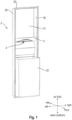
- Fig. 1 is a perspective front view of a recessed dispenser cabinet 2 in which the dispensing mechanism 1 of the present disclosure can be mounted.
- the recessed cabinet 2 comprises a first side wall 29, a second side wall 30 opposing the first side wall 29 and a rear wall 31 extending between the first side wall 29 and the second side wall 30.
- the recessed cabinet 2 is provided with an abutting portion 32 which is configured to abut on the wall when the cabinet 2 is installed in the wall.
- the recessed cabinet 2 comprises a bottom wall 3 which is attached to the cabinet 2 and in which a dispensing opening 4 is provided.
- the recessed cabinet 2 further comprises a bin 23 which is for disposal of used sheet products.
- Fig. 2 is a perspective front view of the set of the present disclosure comprising the dispensing mechanism 1 according to an embodiment and the mounting structure 6 according to a first embodiment.
- the dispensing mechanism 1 comprises a magazine part 24 for accommodating a stack of sheet products and a dispensing part 25 for dispensing the sheet products. In the dispensing mechanism 1 of this embodiment, the sheet products are dispensed from the top of the stack.
- the magazine part 24 and the dispensing part 25 are respectively attached to a frame 26 of the dispensing mechanism 1.
- the frame 26 comprises a left side wall and a right side wall, respectively connected to the left side and the right side of the magazine part 24 and the dispensing part 25.
- the dispensing mechanism comprises an upper portion 8 located at an upper end portion of the frame 26.
- Each of the left side wall and the right side wall of the frame 26 comprises a lower portion, the lower portion comprising a first connection portion 5.
- Each of the first connection portions 5 is attached to a second connection portion 7 of the mounting structure 6.
- the mounting structure 6 is bar-shaped and comprises an elongated shape extending in the left-right direction with respect to the recessed cabinet 2. Furthermore, the mounting structure 6 according to the first embodiment comprises two clips 11 as fastening members 9 for fastening the mounting structure 6 to the bottom wall 3 of the dispenser cabinet 2.
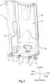
- Fig. 3 is a perspective top view of the mounting structure 6 of the first embodiment being fastened to the bottom wall 3 of the recessed dispenser cabinet 2 of Fig. 1 .
- the length of the mounting structure 6 in the left-right direction is almost as long as the length of the bottom wall 3 and the left-right direction.
- the mounting structure 6 is sized so as to fit to a rear portion of the bottom wall 3 located between the rear edge 10 of the dispensing opening 4 and the rear end of the bottom wall 3. With this configuration, the mounting structure 6 does not cover the dispensing opening 4 of the bottom wall 3.
- the clips 11 are configured to be fastenable to the rear edge 10 of the dispensing opening 4. Therefore, when the sheet products are dispensed through the dispensing opening 4, a protruding part of the leading sheet product will obscure the clips 11, thereby obtaining improving good appearance of the recessed dispenser.
- the second connection portion 7 of the mounting structure comprises a substantially cylindrical shape. More specifically, only certain parts of the second connection portion 7 comprise the cylindrical shape.
- the clips 11 are provided with arrow markings, wherein the arrows point into the direction in which the clips 11 have to be moved in order to fasten the mounting structure 6 to the bottom wall 3.
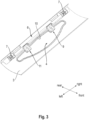
- Fig. 4 is a side view of the set of Fig. 2 , wherein the mounting structure 6 is fastened to the bottom wall 3, while the dispensing mechanism 1 is in a slanted position with respect to the recessed cabinet 2.
- the first connection portion 5 of the dispensing mechanism 1 is pivotably attachable to the second connection portion 7 of the mounting structure 6.
- the dispensing mechanism can be readily pivoted into the recessed cabinet 2.
- the upper portion 8 of the dispensing mechanism 1 can be attached to the rear wall of the recessed cabinet 2.
- Fig. 5 is a perspective lower view of the first connection portion 5 of the dispensing mechanism 1 of Fig. 2 .
- the first connection portion 5 comprises a U-shape which is configured to be engageable with the respective cylindrical shape of the second connection portion 7 of the mounting structure 6. Hence, with this configuration, it is possible to pivot the dispensing mechanism 1 about the mounting structure 6.
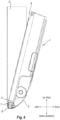
- Fig. 6 is a side view of the set of Fig. 2 being mounted within the recessed cabinet 2 of Fig. 1 .
- the dispensing mechanism 1 may have been pivoted into the recessed cabinet 2.
- the whole dispensing mechanism 1 is supported by the mounting structure 6 and no further mounting means, except for the optional attachment of the upper portion 8 to the dispenser cabinet 2, is required for mounting the dispensing mechanism 1 in the recessed cabinet 2.
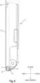
- Fig. 7 is a perspective view of the mounting structure 6 of the first embodiment.
- Fig. 9 is a perspective view of the clip 11 of the mounting structure 6 of the first embodiment.
- the clip 11 comprises a spring clip 12 and a clip body 13 encasing the spring clip 12.
- the clip body 13 and the spring clip 12 respectively have a U-shape.
- the clip body 13 comprises two legs 13a, 13b integrally connected with each other so as to form the U-shape of the clip 11.
- the mounting structure 6 comprises slot openings 14.
- One of the two legs 13a penetrates the slot opening 14 of the mounting structure 6.
- the one of the two legs 13a comprises a protrusion portion integrally formed with the leg 13a, as can be seen in Fig. 9 .
- the other of the two legs 13b is arranged at a lower position in the up-down direction of the recessed cabinet 2 compared to the mounting structure 6.
- the mounting structure 6 is arranged on a top side of the bottom wall 3, while the other of the two legs 13b is arranged on the bottom side of the bottom wall 3, as seen in the up-down direction.
- the leg of the spring clip 12 arranged adjacent to the other of the two legs 13b may comprise a bent portion 27 which, when the mounting structure 6 is fastened to the bottom wall 3, abuts on the bottom side of the bottom wall 3.
- the mounting structure 6 is fastened to the bottom wall 3 by placing the mounting structure 6 on a rear portion of the bottom wall 3 and pushing the clips 11 into the rear direction, i.e. the direction indicated by the arrow marking on the clip body 13, which causes the clips 11 to encompass the rear edge 10 of the dispensing opening 4.
- the spring clip 12 is in a loaded state, thereby pressing and fastening the mounting structure to the bottom wall 3.
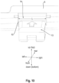
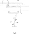
- Figs. 10 and 11 illustrate how the clip 11 is connected to the mounting structure 6. While Fig. 10 is a perspective front view of the mounting structure 6 of the first embodiment, wherein the clip 11 of Fig. 9 penetrates a slot opening 14, Fig. 11 is a perspective rear view thereof. As can be seen in Fig. 10 , the slot opening 14 of the mounting structure 6 has an elongated shape having a longitudinal axis corresponding to the left-right direction. In this case, the slot opening 14 may have a slot length L along its longitudinal axis. As can be seen in Fig. 11 , the one of the two legs 13a of the clip body 13 penetrates the slot opening 14.
- the protrusion portion 15 of the one of the two legs 13a extends in a direction parallel to the longitudinal axis of the slot opening 14 and has a length which is longer than the slot length L.
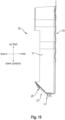
- Fig. 8 is a perspective view of a mounting structure 6 according to a second embodiment.
- the mounting structure 6 as regards the overall shape of the mounting structure 6 and the second connection portions 7, the mounting structure 6 essentially has the same characteristics as the mounting structure 6 of the first embodiment.
- the second embodiment of the mounting structure 6 differs from the first embodiment thereof in the fastening member 9.
- the fastening member 9 is a clamp 22.
- An enlarged view of the clamp 22 is illustrated in Fig. 12 .
- the clamp 22 comprises a lower U-shaped portion, the U-shaped portion comprising two legs. Similar to the first embodiment of the mounting structure 6, one of the two legs of the lower U-shaped portion penetrates the mounting structure 6, whereas the other of the two legs of the lower U-shaped portion encompasses the rear edge 10 of the dispensing opening 4 when the mounting structure 6 is fastened to the bottom wall 3 of the recessed cabinet 2, as can be seen in Fig. 13 .
- the one of the two legs of the lower U-shaped portion of the clamp 22 is connected to a lever 28.
- the lever 28 is rotatably connected to the lower U-shaped portion of the clamp 22 in an eccentric-type manner. More specifically, when the lever 28 of the clamp 22 is rotated with respect to the lower U-shaped portion of the clamp 22, the clamp 22 changes from an unloaded state to a loaded state or vice versa. In Fig. 12 , when the lever 28 points in an upper direction, the clamp 22 is in the loaded state and, when the lever 28 points in a front direction, the clamp 22 is in the unloaded state.
- the lever 28 of the clamp 22 points in an upper direction, that is the clamp 22 is in the loaded state, thereby pressing and fastening the mounting structure 6 against the bottom wall 3.
- the lever 28 may abut on the rear wall of the recessed cabinet 2 when the clamp 22 is in the loaded state.
- the mounting structure 6 comprising the second connection portion 7 is placed on the bottom wall 3 of the recessed cabinet 2.
- the mounting structure 6 is fastened to the bottom wall 3, for example, by means of the clips 11 or the clamps 22 described above or a combination thereof.
- the first connection portion 5 provided at a lower portion of the dispensing mechanism 1 is attached to the second connection portion 7 of the mounting structure 6. If the first connection portion 5 is pivotably attachable to the second connection portion 7 and the dispensing mechanism 1 is attached to the mounting structure 6 while being positioned in a slanted position with respect to the recessed cabinet 2, in the fourth step, the dispensing mechanism 1 is pivoted into the dispenser cabinet 2.
- the upper portion 8 of the dispensing mechanism 1 is attached to the dispenser cabinet 2.
- Fig. 14 is a perspective front view of the dispenser 16 according to the embodiment.
- the dispenser 16 comprises a first side wall 17, a second side wall 18 opposing the first side wall 17, a rear wall 19 extending between the first side wall 17 and the second side wall 18, and a lower wall structure 20 being connected to lower ends of the first side wall 17, the second side wall 18, and the rear wall 19.
- the first side wall 17, the second side wall 18, the rear wall 19, and the lower wall structure 20 form a storage compartment for accommodating a stack of sheet products.
- the lower wall structure 20 defines a dispensing outlet 21 for dispensing the sheet products. As can be seen in Fig.
- the rear wall 19 is composed of two rear wall parts 19a, 19b which are movably arranged relative to each other such that the space of the storage compartment can be adapted in the direction from the first side wall 17 to the second side wall 18, i.e. in a left-right direction of the recessed cabinet 2.
- the lower wall structure 20 is composed of two lower wall structure parts 20a, 20b. This configuration allows for an adaption of the dispenser 16 to the size of the sheet products.
- Fig. 15 is a cross-sectional side view of the dispenser 16 of Fig. 14 .
- the lower wall structure 20 comprises a clip 11 as fastening member 9 for fastening the dispenser 16 to the rear edge 10 of the dispensing opening 4 of the recessed cabinet 2.
- the clip 11 is the same or has the same features as the clip 11 described above with respect to the first embodiment of the mounting structure 6.
- the clamp 22 described above with respect to the second embodiment of the mounting structure 6 can be used as fastening member for fastening the dispenser 16 within the recessed cabinet 2.
Landscapes
- Health & Medical Sciences (AREA)
- Public Health (AREA)
- Details Of Rigid Or Semi-Rigid Containers (AREA)
- Connection Of Plates (AREA)
- Containers And Packaging Bodies Having A Special Means To Remove Contents (AREA)
- Devices For Dispensing Beverages (AREA)
- Drawers Of Furniture (AREA)
Claims (25)
- Satz zum Montieren eines Ausgabemechanismus (1) zum Ausgeben von Blattprodukten in einem vorhandenen Ausgabeschrank (2), der eine Bodenwand (3) mit einer Ausgabeöffnung (4) umfasst, wobei der Satz umfasst:den Ausgabemechanismus (1), wobei der Ausgabemechanismus (1) einen unteren Abschnitt umfasst, wobei der untere Abschnitt einen ersten Verbindungsabschnitt (5) umfasst,eine Befestigungsstruktur (6), die einen zweiten Verbindungsabschnitt (7) umfasst, an dem der erste Verbindungsabschnitt (5) des unteren Abschnitts befestigt werden kann, um den Ausgabemechanismus (1) zu tragen,wobei die Befestigungsstruktur (6) so konfiguriert ist, dass sie an der Bodenwand (3) befestigt werden kann,dadurch gekennzeichnet, dassder erste Verbindungsabschnitt (5) schwenkbar an dem zweiten Verbindungsabschnitt (7) befestigt werden kann.
- Satz nach Anspruch 1,wobei der zweite Verbindungsabschnitt (7) eine im Wesentlichen zylindrische Form umfasst,wobei der erste Verbindungsabschnitt (5) im Wesentlichen U-förmig ist und mit dem zweiten Verbindungsabschnitt (7) in Eingriff gebracht werden kann.
- Satz nach einem der vorstehenden Ansprüche,
wobei der Ausgabemechanismus (1) weiter einen oberen Abschnitt (8) umfasst, wobei der obere Abschnitt (8) an dem Ausgabeschrank (2) befestigt werden kann. - Satz nach einem der vorstehenden Ansprüche,
wobei der erste Verbindungsabschnitt (5) auf oder in den zweiten Verbindungsabschnitt (7) einschnappbar ist. - Satz nach einem der vorstehenden Ansprüche,
wobei die Befestigungsstruktur (6) ein Befestigungselement (9) umfasst, das so konfiguriert ist, dass es an einem Rand der Ausgabeöffnung (4) befestigt werden kann. - Satz nach Anspruch 5,
wobei das Befestigungselement (9) so konfiguriert ist, dass es an einem hinteren Rand (10) der Ausgabeöffnung (4) befestigt werden kann. - Satz nach Anspruch 5 oder 6,
wobei das Befestigungselement (9) der Befestigungsstruktur (6) so konfiguriert ist, dass es an der Bodenwand (3) befestigt werden kann, ohne die Bodenwand (3) strukturell zu verändern. - Satz nach einem der Ansprüche 5 bis 7,
wobei das Befestigungselement (9) aus der Gruppe ausgewählt ist, die aus einer Klemme (11), einer Klammer (22), einem Band, einem Klettverschluss und Kombinationen dieser besteht. - Satz nach Anspruch 8,
wobei das Befestigungselement (9) eine Klemme (11) ist, wobei die Klemme (11) eine Federklemme (12) mit einem im Wesentlichen U-förmigen Querschnitt umfasst. - Satz nach Anspruch 9,
wobei die Klemme (11) weiter einen Klemmenkörper (13) umfasst, der einen im Wesentlichen U-förmigen Querschnitt aufweist und die Federklemme (12) umschließt. - Satz nach Anspruch 10,wobei die Befestigungsstruktur (6) eine oder mehr als eine Schlitzöffnung (14) umfasst, wobei die Schlitzöffnung (14) eine Schlitzlänge (L) entlang ihrer Längsachse aufweist,wobei der Klemmenkörper (13) zwei Schenkel (13a, 13b) umfasst, wobei einer der beiden Schenkel (13a, 13b) in die Schlitzöffnung (14) eindringt, wobei der eine der beiden Schenkel (13a, 13b) einen vorstehenden Abschnitt (15) umfasst, der sich in einer Richtung parallel zu der Längsachse der Schlitzöffnung (14) erstreckt und eine Länge aufweist, die länger ist als die Schlitzlänge (L).
- Satz nach einem der vorstehenden Ansprüche,
wobei die Befestigungsstruktur (6) im Wesentlichen stabförmig ist. - Satz nach Anspruch 12,
wobei die Befestigungsstruktur (6) in ihrer Länge in Längsrichtung verstellbar ist. - Satz nach einem der vorstehenden Ansprüche,
wobei der Satz so konfiguriert ist, dass der Ausgabemechanismus (1) in einem Einbauschrank wie dem vorhandenen Ausgabeschrank (2) montiert werden kann. - Verfahren zum Montieren eines Ausgabemechanismus (1) zum Ausgeben von Blattprodukten in einem vorhandenen Ausgabeschrank (2), der eine Bodenwand (3) mit einer Ausgabeöffnung (4) umfasst, wobei das Verfahren die folgenden Schritte umfasst:i) Anbringen einer Befestigungsstruktur (6), die einen zweiten Verbindungsabschnitt (7) an der Bodenwand (3) umfasst,ii) Befestigen der Befestigungsstruktur (6) an der Bodenwand (3),iii) Anbringen eines ersten Verbindungsabschnitts (5), der an einem unteren Abschnitt des Ausgabemechanismus (1) bereitgestellt ist, an dem zweiten Verbindungsabschnitt (7) der Befestigungsstruktur (6),wobei der erste Verbindungsabschnitt (5) schwenkbar an dem zweiten Verbindungsabschnitt (7) angebracht werden kann,wobei das Verfahren auf den Schritt iii) folgend weiter den folgenden Schritt umfasst:
iv) Schwenken des Ausgabemechanismus (1) in den Ausgabeschrank (2). - Verfahren nach Anspruch 15,
wobei das Verfahren auf den Schritt iv) folgend weiter den folgenden Schritt umfasst:
v) Anbringen eines oberen Abschnitts (8) des Ausgabemechanismus (1) an dem Ausgabeschrank (2). - Verfahren nach Anspruch 15 oder 16,
wobei der Ausgabemechanismus (1) in einem Einbauschrank wie dem vorhandenen Ausgabeschrank (2) montiert ist. - Spender (16) zum Montieren in einen vorhandenen Ausgabeschrank (2), der eine Bodenwand (3) mit einer Ausgabeöffnung (4) umfasst, wobei der Spender (16) Folgendes umfasst:eine erste Seitenwand (17),eine zweite Seitenwand (18), die der ersten Seitenwand (17) gegenüberliegt,eine Rückwand (19), die sich zwischen der ersten Seitenwand (17) und der zweiten Seitenwand (18) erstreckt,eine untere Wandstruktur (20), die mit den unteren Enden der ersten Seitenwand (17), der zweiten Seitenwand (18) und der Rückwand (19) verbunden ist,wobei die erste Seitenwand (17), die zweite Seitenwand (18), die Rückwand (19) und die untere Wandstruktur (20) ein Lagerfach zur Aufnahme eines Stapels von Blattprodukten bilden,wobei die untere Wandstruktur (20) einen Ausgabeauslass (21) für die Ausgabe der Blattprodukte definiert,dadurch gekennzeichnet, dassdie untere Wandstruktur (20) so konfiguriert ist, dass sie an der Bodenwand (3) befestigt werden kann,wobei die untere Wandstruktur (20) ein Befestigungselement (9) umfasst, das so konfiguriert ist, dass es an einem Rand der Ausgabeöffnung (4) befestigt werden kann,wobei das Befestigungselement (9) aus der Gruppe ausgewählt ist, die aus einer Klemme (11), einer Klammer (22), einem Band, einem Klettverschluss und Kombinationen dieser besteht.
- Spender (16) nach Anspruch 18,
wobei die Rückwand (19) an dem Ausgabeschrank (2) befestigbar ist. - Spender (16) nach Anspruch 18 oder 19,
wobei das Befestigungselement (9) so konfiguriert ist, dass es an einem hinteren Rand (10) der Ausgabeöffnung (4) befestigt werden kann. - Spender (16) nach einem der Ansprüche 18 bis 20,
wobei das Befestigungselement (9) der unteren Wandstruktur (20) so konfiguriert ist, dass es an der Bodenwand (3) befestigt werden kann, ohne die Bodenwand (3) strukturell zu verändern. - Spender (16) nach einem der Ansprüche 18 bis 21,
wobei das Befestigungselement (9) eine Klemme (11) ist, wobei die Klemme (11) eine Federklemme (12) mit einem im Wesentlichen U-förmigen Querschnitt umfasst. - Spender (16) nach Anspruch 22,
wobei die Klemme (11) weiter einen Klemmenkörper (13) umfasst, der einen im Wesentlichen U-förmigen Querschnitt aufweist und die Federklemme (12) umschließt. - Spender (16) nach Anspruch 23,wobei die untere Wandstruktur (20) eine oder mehr als eine Schlitzöffnung (14) umfasst, wobei die Schlitzöffnung (14) eine Schlitzlänge (L) entlang ihrer Längsachse aufweist,wobei der Klemmenkörper (13) zwei Schenkel (13a, 13b) umfasst, wobei einer der beiden Schenkel (13a, 13b) in die Schlitzöffnung (14) eindringt, wobei der eine der beiden Schenkel (13a, 13b) einen vorstehenden Abschnitt (15) umfasst, der sich in einer Richtung parallel zu der Längsachse der Schlitzöffnung (14) erstreckt und eine Länge aufweist, die länger ist als die Schlitzlänge (L).
- Spender (16) nach einem der Ansprüche 18 bis 24,
wobei der Spender (16) so konfiguriert ist, dass er in einem Einbauschrank wie dem vorhandenen Ausgabeschrank (2) montiert werden kann.
Applications Claiming Priority (1)
| Application Number | Priority Date | Filing Date | Title |
|---|---|---|---|
| PCT/EP2019/055970 WO2020182283A1 (en) | 2019-03-11 | 2019-03-11 | Dispenser for dispensing sheet products |
Publications (3)
| Publication Number | Publication Date |
|---|---|
| EP3937745A1 EP3937745A1 (de) | 2022-01-19 |
| EP3937745C0 EP3937745C0 (de) | 2025-01-29 |
| EP3937745B1 true EP3937745B1 (de) | 2025-01-29 |
Family
ID=65812283
Family Applications (1)
| Application Number | Title | Priority Date | Filing Date |
|---|---|---|---|
| EP19711537.1A Active EP3937745B1 (de) | 2019-03-11 | 2019-03-11 | Spender zur ausgabe von blattprodukten |
Country Status (7)
| Country | Link |
|---|---|
| US (1) | US12446737B2 (de) |
| EP (1) | EP3937745B1 (de) |
| CN (1) | CN113423315B (de) |
| CA (1) | CA3131042A1 (de) |
| ES (1) | ES3013120T3 (de) |
| MX (1) | MX2021010985A (de) |
| WO (1) | WO2020182283A1 (de) |
Families Citing this family (1)
| Publication number | Priority date | Publication date | Assignee | Title |
|---|---|---|---|---|
| WO2022199798A1 (en) * | 2021-03-23 | 2022-09-29 | Essity Hygiene And Health Aktiebolag | Dispensing device comprising a face mask support element |
Family Cites Families (40)
| Publication number | Priority date | Publication date | Assignee | Title |
|---|---|---|---|---|
| US372181A (en) * | 1887-10-25 | Joseph james speed | ||
| US1371982A (en) * | 1918-08-16 | 1921-03-15 | Aubrey C Sartin | Match-holder |
| US2932426A (en) * | 1955-03-18 | 1960-04-12 | Fort Howard Paper Co | Dispensing devices for paper towels |
| US3028047A (en) * | 1958-03-11 | 1962-04-03 | Crown Zellerbach Corp | Dispenser receptacle for folded sheets |
| US3263860A (en) * | 1964-07-07 | 1966-08-02 | Ct Mint Co | Article dispenser including a reciprocating ejector |
| US3432217A (en) | 1967-10-17 | 1969-03-11 | Bobrick Corp | Recessed washroom dispenser and method of installing the same |
| US4260896A (en) * | 1978-07-17 | 1981-04-07 | E. I. Du Pont De Nemours & Co. | X-ray unit |
| US4448462A (en) * | 1980-08-20 | 1984-05-15 | Steiner Corporation | Towel dispenser |
| US5054777A (en) * | 1991-01-11 | 1991-10-08 | Borden Teddy H | Golf accessory |
| US5154496A (en) * | 1991-05-13 | 1992-10-13 | James River Ii, Inc. | Roll towel cabinet mounting system |
| US5322186A (en) * | 1993-06-14 | 1994-06-21 | Scott Paper Company | Retrofit folded towel dispensing module |
| FR2750958B1 (fr) * | 1996-07-12 | 1998-11-20 | Jamont N V | Distributeur de papier comportant une cassette amovible |
| US5950863A (en) * | 1997-08-05 | 1999-09-14 | Perrin Manufacturing | Sheet dispenser insert |
| US5857642A (en) * | 1997-08-25 | 1999-01-12 | Hygiene Systems, Inc. | Paper towel dispenser |
| US6003723A (en) * | 1997-09-02 | 1999-12-21 | Perrin Manufacturing | Large capacity towel dispenser |
| US6785946B2 (en) * | 1999-04-30 | 2004-09-07 | Kimberly-Clark Worldwide, Inc. | System and method for refilling a dispenser |
| US7025301B1 (en) * | 1999-12-30 | 2006-04-11 | Von Drehle Corporation | Dispenser |
| US6622888B2 (en) * | 2001-03-09 | 2003-09-23 | Georgia-Pacific Corporation | Metering napkin dispenser |
| US9010602B2 (en) * | 2002-02-15 | 2015-04-21 | Georgia-Pacific Consumer Products Lp | Towel dispenser |
| US20050161464A1 (en) * | 2003-09-24 | 2005-07-28 | Salvatore Fiola | Holder for flaccid flat articles such as napkins |
| US8215520B2 (en) * | 2003-10-17 | 2012-07-10 | Rock-Tenn Shared Services, Llc | Secure merchandising system |
| WO2008042961A2 (en) * | 2006-10-03 | 2008-04-10 | Georgia-Pacific Consumer Products Lp | Automated tissue dispenser |
| NZ550472A (en) * | 2006-10-11 | 2009-03-31 | Durapod Systems Ltd | Dispensing apparatus |
| EP2060218B1 (de) * | 2007-11-13 | 2017-01-04 | Sca Tissue France | System zum Erhöhen der Wasserfestigkeit eines Rollenspenders |
| US7997443B2 (en) * | 2007-11-13 | 2011-08-16 | Cintas Corporation | Center-pull paper towel dispenser |
| WO2010063727A1 (en) | 2008-12-01 | 2010-06-10 | Sca Hygiene Products Ab | Dispenser |
| HUP0900005A2 (en) * | 2009-01-06 | 2010-07-28 | Andras Fodor | Towel dispenser and collector |
| US20110011879A1 (en) * | 2009-07-17 | 2011-01-20 | Julie Johnson | Clippable Portable Tissue Dispenser |
| US9572460B2 (en) * | 2009-08-13 | 2017-02-21 | Wausau Paper Towel & Tissue, Llc | Towel dispenser |
| MX364522B (es) * | 2011-03-10 | 2019-04-30 | Essity Hygiene & Health Ab | Despachador con ventosas. |
| HUE028107T2 (en) | 2011-07-13 | 2016-11-28 | Sca Hygiene Prod Ab | Adhesive Product Dispenser and Rack |
| ES2638307T3 (es) * | 2011-12-20 | 2017-10-19 | Sca Tissue France | Dispensador de producto en hojas |
| US10058221B2 (en) | 2012-10-26 | 2018-08-28 | Sca Hygiene Products Ab | Dispenser |
| RU2015121231A (ru) * | 2012-12-19 | 2017-01-26 | Ска Хайджин Продактс Аб | Раздаточное устройство и способ пополнения раздаточного устройства |
| WO2014200394A1 (en) | 2013-06-10 | 2014-12-18 | Sca Hygiene Products Ab | Dispenser for a stack of web material |
| CN112773237B (zh) * | 2014-06-19 | 2023-09-08 | 易希提卫生与保健公司 | 分配器和再装填分配器的方法 |
| BR112017000994A2 (pt) * | 2014-07-28 | 2017-12-19 | Bemis Co Inc | recipiente de lenço umedecido com dispensação pelo fundo |
| KR101535040B1 (ko) | 2014-11-24 | 2015-07-08 | 박정식 | 핸드타월 배출 장치 |
| EP3261504B1 (de) | 2015-02-23 | 2023-02-22 | Essity Hygiene and Health Aktiebolag | Spender für einen bahnmaterialstapel |
| US10143340B2 (en) * | 2015-06-17 | 2018-12-04 | Essity Hygiene And Health Aktiebolag | Dispenser assembly and related methods |
-
2019
- 2019-03-11 CN CN201980092176.5A patent/CN113423315B/zh active Active
- 2019-03-11 EP EP19711537.1A patent/EP3937745B1/de active Active
- 2019-03-11 MX MX2021010985A patent/MX2021010985A/es unknown
- 2019-03-11 ES ES19711537T patent/ES3013120T3/es active Active
- 2019-03-11 CA CA3131042A patent/CA3131042A1/en active Pending
- 2019-03-11 WO PCT/EP2019/055970 patent/WO2020182283A1/en not_active Ceased
- 2019-03-11 US US17/428,418 patent/US12446737B2/en active Active
Also Published As
| Publication number | Publication date |
|---|---|
| ES3013120T3 (en) | 2025-04-11 |
| EP3937745C0 (de) | 2025-01-29 |
| US20220133100A1 (en) | 2022-05-05 |
| EP3937745A1 (de) | 2022-01-19 |
| US12446737B2 (en) | 2025-10-21 |
| CA3131042A1 (en) | 2020-09-17 |
| WO2020182283A1 (en) | 2020-09-17 |
| MX2021010985A (es) | 2021-10-13 |
| CN113423315B (zh) | 2023-07-18 |
| CN113423315A (zh) | 2021-09-21 |
Similar Documents
| Publication | Publication Date | Title |
|---|---|---|
| US9572460B2 (en) | Towel dispenser | |
| CA2635260C (en) | Paper towel cabinet with paper towel support bar | |
| US9498095B2 (en) | Gravity feed dispenser | |
| US20040206769A1 (en) | Container and cartridge for dispensing paper products | |
| US8978925B2 (en) | Paper towel cabinet with paper towel module | |
| EP3937745B1 (de) | Spender zur ausgabe von blattprodukten | |
| US20130213992A1 (en) | Dispenser for paper sheets | |
| EP3937746B1 (de) | Spender zur ausgabe von blattprodukten | |
| EP3612067B1 (de) | Spender zur ausgabe von blattprodukten | |
| HK40056563A (en) | Dispenser for dispensing sheet products | |
| US2893616A (en) | Web dispenser | |
| US7051972B2 (en) | Roll dispenser | |
| US10682022B2 (en) | Precut wiping material dispenser, method for implementing and method for adjusting such a dispenser | |
| KR101580636B1 (ko) | 비닐롤백 낱장 분리장치 | |
| HK40014211B (en) | Dispenser for dispensing sheet products | |
| HK40014211A (en) | Dispenser for dispensing sheet products | |
| GB2489733A (en) | Tag dispenser | |
| HK1235643A1 (en) | Dispenser for interfolded napkins |
Legal Events
| Date | Code | Title | Description |
|---|---|---|---|
| STAA | Information on the status of an ep patent application or granted ep patent |
Free format text: STATUS: UNKNOWN |
|
| STAA | Information on the status of an ep patent application or granted ep patent |
Free format text: STATUS: THE INTERNATIONAL PUBLICATION HAS BEEN MADE |
|
| PUAI | Public reference made under article 153(3) epc to a published international application that has entered the european phase |
Free format text: ORIGINAL CODE: 0009012 |
|
| STAA | Information on the status of an ep patent application or granted ep patent |
Free format text: STATUS: REQUEST FOR EXAMINATION WAS MADE |
|
| 17P | Request for examination filed |
Effective date: 20211008 |
|
| AK | Designated contracting states |
Kind code of ref document: A1 Designated state(s): AL AT BE BG CH CY CZ DE DK EE ES FI FR GB GR HR HU IE IS IT LI LT LU LV MC MK MT NL NO PL PT RO RS SE SI SK SM TR |
|
| DAV | Request for validation of the european patent (deleted) | ||
| DAX | Request for extension of the european patent (deleted) | ||
| GRAP | Despatch of communication of intention to grant a patent |
Free format text: ORIGINAL CODE: EPIDOSNIGR1 |
|
| STAA | Information on the status of an ep patent application or granted ep patent |
Free format text: STATUS: GRANT OF PATENT IS INTENDED |
|
| INTG | Intention to grant announced |
Effective date: 20240425 |
|
| GRAJ | Information related to disapproval of communication of intention to grant by the applicant or resumption of examination proceedings by the epo deleted |
Free format text: ORIGINAL CODE: EPIDOSDIGR1 |
|
| STAA | Information on the status of an ep patent application or granted ep patent |
Free format text: STATUS: REQUEST FOR EXAMINATION WAS MADE |
|
| GRAP | Despatch of communication of intention to grant a patent |
Free format text: ORIGINAL CODE: EPIDOSNIGR1 |
|
| STAA | Information on the status of an ep patent application or granted ep patent |
Free format text: STATUS: GRANT OF PATENT IS INTENDED |
|
| INTC | Intention to grant announced (deleted) | ||
| INTG | Intention to grant announced |
Effective date: 20240821 |
|
| GRAS | Grant fee paid |
Free format text: ORIGINAL CODE: EPIDOSNIGR3 |
|
| GRAA | (expected) grant |
Free format text: ORIGINAL CODE: 0009210 |
|
| STAA | Information on the status of an ep patent application or granted ep patent |
Free format text: STATUS: THE PATENT HAS BEEN GRANTED |
|
| AK | Designated contracting states |
Kind code of ref document: B1 Designated state(s): AL AT BE BG CH CY CZ DE DK EE ES FI FR GB GR HR HU IE IS IT LI LT LU LV MC MK MT NL NO PL PT RO RS SE SI SK SM TR |
|
| REG | Reference to a national code |
Ref country code: GB Ref legal event code: FG4D |
|
| REG | Reference to a national code |
Ref country code: CH Ref legal event code: EP |
|
| REG | Reference to a national code |
Ref country code: DE Ref legal event code: R096 Ref document number: 602019065366 Country of ref document: DE |
|
| REG | Reference to a national code |
Ref country code: IE Ref legal event code: FG4D |
|
| U01 | Request for unitary effect filed |
Effective date: 20250129 |
|
| U07 | Unitary effect registered |
Designated state(s): AT BE BG DE DK EE FI FR IT LT LU LV MT NL PT RO SE SI Effective date: 20250204 |
|
| REG | Reference to a national code |
Ref country code: ES Ref legal event code: FG2A Ref document number: 3013120 Country of ref document: ES Kind code of ref document: T3 Effective date: 20250411 |
|
| U20 | Renewal fee for the european patent with unitary effect paid |
Year of fee payment: 7 Effective date: 20250325 |
|
| PG25 | Lapsed in a contracting state [announced via postgrant information from national office to epo] |
Ref country code: RS Free format text: LAPSE BECAUSE OF FAILURE TO SUBMIT A TRANSLATION OF THE DESCRIPTION OR TO PAY THE FEE WITHIN THE PRESCRIBED TIME-LIMIT Effective date: 20250429 |
|
| PG25 | Lapsed in a contracting state [announced via postgrant information from national office to epo] |
Ref country code: PL Free format text: LAPSE BECAUSE OF FAILURE TO SUBMIT A TRANSLATION OF THE DESCRIPTION OR TO PAY THE FEE WITHIN THE PRESCRIBED TIME-LIMIT Effective date: 20250129 |
|
| PGFP | Annual fee paid to national office [announced via postgrant information from national office to epo] |
Ref country code: ES Payment date: 20250423 Year of fee payment: 7 |
|
| PG25 | Lapsed in a contracting state [announced via postgrant information from national office to epo] |
Ref country code: NO Free format text: LAPSE BECAUSE OF FAILURE TO SUBMIT A TRANSLATION OF THE DESCRIPTION OR TO PAY THE FEE WITHIN THE PRESCRIBED TIME-LIMIT Effective date: 20250429 Ref country code: IS Free format text: LAPSE BECAUSE OF FAILURE TO SUBMIT A TRANSLATION OF THE DESCRIPTION OR TO PAY THE FEE WITHIN THE PRESCRIBED TIME-LIMIT Effective date: 20250529 |
|
| PG25 | Lapsed in a contracting state [announced via postgrant information from national office to epo] |
Ref country code: HR Free format text: LAPSE BECAUSE OF FAILURE TO SUBMIT A TRANSLATION OF THE DESCRIPTION OR TO PAY THE FEE WITHIN THE PRESCRIBED TIME-LIMIT Effective date: 20250129 |
|
| PG25 | Lapsed in a contracting state [announced via postgrant information from national office to epo] |
Ref country code: GR Free format text: LAPSE BECAUSE OF FAILURE TO SUBMIT A TRANSLATION OF THE DESCRIPTION OR TO PAY THE FEE WITHIN THE PRESCRIBED TIME-LIMIT Effective date: 20250430 |
|
| PG25 | Lapsed in a contracting state [announced via postgrant information from national office to epo] |
Ref country code: SM Free format text: LAPSE BECAUSE OF FAILURE TO SUBMIT A TRANSLATION OF THE DESCRIPTION OR TO PAY THE FEE WITHIN THE PRESCRIBED TIME-LIMIT Effective date: 20250129 |
|
| PG25 | Lapsed in a contracting state [announced via postgrant information from national office to epo] |
Ref country code: MC Free format text: LAPSE BECAUSE OF FAILURE TO SUBMIT A TRANSLATION OF THE DESCRIPTION OR TO PAY THE FEE WITHIN THE PRESCRIBED TIME-LIMIT Effective date: 20250129 |
|
| PG25 | Lapsed in a contracting state [announced via postgrant information from national office to epo] |
Ref country code: CZ Free format text: LAPSE BECAUSE OF FAILURE TO SUBMIT A TRANSLATION OF THE DESCRIPTION OR TO PAY THE FEE WITHIN THE PRESCRIBED TIME-LIMIT Effective date: 20250129 |
|
| REG | Reference to a national code |
Ref country code: CH Ref legal event code: H13 Free format text: ST27 STATUS EVENT CODE: U-0-0-H10-H13 (AS PROVIDED BY THE NATIONAL OFFICE) Effective date: 20251023 |
|
| PG25 | Lapsed in a contracting state [announced via postgrant information from national office to epo] |
Ref country code: SK Free format text: LAPSE BECAUSE OF FAILURE TO SUBMIT A TRANSLATION OF THE DESCRIPTION OR TO PAY THE FEE WITHIN THE PRESCRIBED TIME-LIMIT Effective date: 20250129 |
|
| PLBE | No opposition filed within time limit |
Free format text: ORIGINAL CODE: 0009261 |
|
| STAA | Information on the status of an ep patent application or granted ep patent |
Free format text: STATUS: NO OPPOSITION FILED WITHIN TIME LIMIT |
|
| 26N | No opposition filed |
Effective date: 20251030 |
|
| PG25 | Lapsed in a contracting state [announced via postgrant information from national office to epo] |
Ref country code: CH Free format text: LAPSE BECAUSE OF NON-PAYMENT OF DUE FEES Effective date: 20250331 |
|
| PG25 | Lapsed in a contracting state [announced via postgrant information from national office to epo] |
Ref country code: IE Free format text: LAPSE BECAUSE OF NON-PAYMENT OF DUE FEES Effective date: 20250311 |
|
| PGFP | Annual fee paid to national office [announced via postgrant information from national office to epo] |
Ref country code: GB Payment date: 20260319 Year of fee payment: 8 |
|
| PGFP | Annual fee paid to national office [announced via postgrant information from national office to epo] |
Ref country code: TR Payment date: 20260220 Year of fee payment: 8 |