EP3937610B1 - Kopfhöhensteuerung für einen erntekopf - Google Patents
Kopfhöhensteuerung für einen erntekopf Download PDFInfo
- Publication number
- EP3937610B1 EP3937610B1 EP20717426.9A EP20717426A EP3937610B1 EP 3937610 B1 EP3937610 B1 EP 3937610B1 EP 20717426 A EP20717426 A EP 20717426A EP 3937610 B1 EP3937610 B1 EP 3937610B1
- Authority
- EP
- European Patent Office
- Prior art keywords
- outboard
- inboard
- signal
- correction factor
- height
- Prior art date
- Legal status (The legal status is an assumption and is not a legal conclusion. Google has not performed a legal analysis and makes no representation as to the accuracy of the status listed.)
- Active
Links
Images


Classifications
-
- A—HUMAN NECESSITIES
- A01—AGRICULTURE; FORESTRY; ANIMAL HUSBANDRY; HUNTING; TRAPPING; FISHING
- A01B—SOIL WORKING IN AGRICULTURE OR FORESTRY; PARTS, DETAILS, OR ACCESSORIES OF AGRICULTURAL MACHINES OR IMPLEMENTS, IN GENERAL
- A01B63/00—Lifting or adjusting devices or arrangements for agricultural machines or implements
- A01B63/02—Lifting or adjusting devices or arrangements for agricultural machines or implements for implements mounted on tractors
- A01B63/10—Lifting or adjusting devices or arrangements for agricultural machines or implements for implements mounted on tractors operated by hydraulic or pneumatic means
- A01B63/111—Lifting or adjusting devices or arrangements for agricultural machines or implements for implements mounted on tractors operated by hydraulic or pneumatic means regulating working depth of implements
-
- A—HUMAN NECESSITIES
- A01—AGRICULTURE; FORESTRY; ANIMAL HUSBANDRY; HUNTING; TRAPPING; FISHING
- A01D—HARVESTING; MOWING
- A01D41/00—Combines, i.e. harvesters or mowers combined with threshing devices
- A01D41/12—Details of combines
- A01D41/14—Mowing tables
- A01D41/141—Automatic header control
Definitions
- the position of the header 104 relative to the chassis 102 is controlled by a combine control system 118, which typically is integrated into a cabin or other location within the combine chassis 102.
- the control system 118 receives ground height measurements from height sensors located along the header 104.
- the header 104 may have an outboard left height sensor 120 L , an inboard left height sensor 120 LC , an outboard right height sensor 120 R , and an inboard right height sensor 120 RC .
- Each height sensor 120 provides a signal representative of a measurement of the height of the header 104 above the ground G at the location of the respective sensor 120.
- the control system 118 processes these signals to decide how to operate the actuators 112, 116 to position the header 104.
- US2018368317 (A1 ) describes a harvesting head having a middle section connected to a carrier device and at least one side section connected by an articulated connection to the middle section about which the side section pivots between a lower and an upper limit value.
- the carrier device has a height adjustment device whose adjusting movements are controlled by a control.
- the harvesting head has a sensor transmitting a sensor signal to the evaluation device at least upon pivoting of the side section when a limit value has been achieved during pivoting of the side section to the middle section.
- the evaluation device switches upon the presence of a corresponding sensor signal into a correction mode for height adjustment of the carrier device.
- the evaluation device outputs an adjusting signal in the correction mode to adjust the carrier device up or down by the evaluation device according to the sensor signal.
- WO2018152266 (A1 ) describes a method of height control of a machine attachment during operation at different fore- and-aft pitch angles.
- an agricultural combine having a chassis, a header movably connected to the chassis by a movable mount, and a combine control system configured to operate the movable mount to change an orientation of the header relative to the chassis.
- the header includes a center section extending from a first end to a second end, and a first wing section movably attached to the first end of the center section, the first wing section being movable relative to the center section through a respective range of motion comprising a lower operating range including a lowest operating position, a higher operating range including a highest operating position, and a median operating range between the lower operating range and the higher operating range.
- a first displacement sensor indicates a position of the first wing section within the respective range of movement.
- a method for operating a header on an agricultural combine located on a surface includes: measuring a displacement of an outboard portion of the header relative to an inboard portion of the header; receiving a first measured distance between the inboard portion and the surface, and a second measured distance between the outboard portion and the surface, the first measured distance and the second measured distance comprising a height data set; determining whether the displacement indicates a relatively low degree of displacement of the outboard portion relative to the inboard portion or a relatively high degree of displacement of the outboard portion relative to the inboard portion; upon determining that the displacement indicates a relatively low degree of displacement, generating from the height data set a first control signal comprising a respective inboard height signal and a respective outboard height signal in which the magnitude of the inboard height signal is increased relative to the magnitude of the outboard height signal; and upon determining that the displacement indicates a relatively high degree of displacement, generating from the height data set a second control signal comprising a respective inboard height signal and a respective outboard
- the header 204 is an articulated (or “segmented") header having a center section 218 that extends from a first lateral end to a second lateral end, and a wing section 220 attached at each lateral end of the center section 218.
- the wing sections 220 are movably attached to the respective end of the center section 218 to extend laterally therefrom.
- the wing sections 220 are movably connected to the center section 218 by respective articulated joints 230.
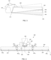
- the articulated joints 230 allow the wing sections 220 to move, relative to the center section 218, through a range of motion such as shown in FIG. 3 .
- Each wing section 220 can move from a lowest operating position 300 to a highest operating position 302.
- the span between the lowest operating position 300 and the highest operating position 302 defines a range of motion including a lower operating range 304 (which includes the lowest operating position 300), a median operating range 306, and a higher operating range 308 (which includes the highest operating position 302).
- the range of motion defines the normal operating range of the wing section 220.
- FIG. 3 shows the lower operating range 304 the wing section 220 being below the center section 218, and the higher operating range 308 the wing section 220 being above the center section 218, this is not strictly required.
- the lowest operating position 300 is at the same height as the center section 218 or just below it, then the lower operating range may extend entirely or mostly above the center section 218.
- the wing sections 220 may be movable beyond the normal operating range during transport or during special operations (e.g. operating the combine to harvest without using the wing section).
- the control system and associated components are part of an agricultural combine vehicle 200 such as discussed above, having a chassis 202, an articulated header 204 and a mount 208.
- the mount 208 is operable to move the header 204 relative to the chassis 202.
- the header 204 has a center section 218 and a wing section 220 attached at each lateral end of the center section 218.
- the exemplary control system includes a signal conditioning unit 400, ground height sensors 402, displacement sensors 404 and a combine control system 406.
- the ground height sensors 402 and displacement sensors 404 are operatively connected to the signal conditioning unit 400 by electrical wiring or wireless communication transmitters and/or receivers.
- the signal conditioning unit 400 is operatively connected to the combine control system 406 in a similar manner.
- the ground height sensors 402 are configured to emit a signal representative of the distance to the ground G.
- the ground height sensors 402 may comprise any suitable distance-measuring device that is operable in the context of a harvesting combine.
- the ground height sensors 402 may comprise ultrasonic, optical or radar rangefinders.
- the ground height sensors 402 also may comprise a mechanical drag arm (i.e., feeler) or drag wheel that is connected to the header 204 by a linear or angular potentiometer to measure distance as a function of changing resistance of the potentiometer, such as known in the art.
- the ground height sensors 402 are mounted to the header 204 at various locations, and calibrated to provide a signal representing the distance between the ground G and the location on the header 204 at which the sensor is attached.
- the outboard height sensors 402 L and 402 R are located on the wing sections 220, with one sensor at the distal end of its respective wing section 220 (i.e., at or near the end located more remotely from the center section 418).
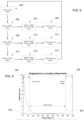
- the displacement sensors 404 are operatively connected to the center section 218 and/or wing sections 220, and each displacement sensor 404 is configured to measure changes in the position of a respective wing section 220 relative to the center section 218.
- the displacement is angular rotation
- each wing section has an associated displacement sensor 404; namely, a left displacement sensor 404 L to measure the angle of the left wing section 220, and a right displacement sensor 404 R to measure the angle of the right wing section 220.
- the displacement sensors 404 may comprise any mechanism suitable for measuring the relative angle between two parts. For example, as shown in FIG.
- a typical conventional combine control system 406 generates control outputs for the actuators 212, 216 by averaging the sensor signals on the two sides of the header 204. For example, the combine control system 406 averages the values of the left-side inboard height sensor signal and the left-side outboard height sensor signal to determine a left-side average height, and averages the values of the right-side inboard height sensor signal and the right-side outboard height sensor signal to determine a right-side average height. Based on these two values, the combine control system 406 issues control signals to raise, lower, or tilt the header.
- the signal processing unit 400 that may be implemented using any suitable arrangement of processors and logical circuits.
- FIG. 7 is a block diagram of exemplary hardware and computing equipment that may be used as a signal processing unit 400 as discussed herein.
- the signal processing unit 400 includes a central processing unit (CPU) 700, which is responsible for performing calculations and logic operations required to execute one or more computer programs or operations.
- the CPU 700 is connected via a data transmission bus 702, to sensors 704 (e.g., sensors 402 and 404), a user interface 706, and a memory 708.
- the user interface 706 may comprise any suitable connection port or the like for programming and customizing the operation of the signal processing unit 400.
Landscapes
- Life Sciences & Earth Sciences (AREA)
- Environmental Sciences (AREA)
- Engineering & Computer Science (AREA)
- Mechanical Engineering (AREA)
- Soil Sciences (AREA)
- Guiding Agricultural Machines (AREA)
- Harvester Elements (AREA)
- Vehicle Body Suspensions (AREA)
Claims (15)
- Vorsatz (204) für ein landwirtschaftliches Fahrzeug (200), wobei der Vorsatz umfasst:einen zentralen Abschnitt (218), der sich von einem ersten Ende zu einem zweiten Ende erstreckt;einen ersten Flügelabschnitt, der an dem ersten Ende des zentralen Abschnitts (218) beweglich befestigt ist, wobei der erste Flügelabschnitt relativ zu dem zentralen Abschnitt über einen Bewegungsbereich beweglich ist, der einen unteren Arbeitsbereich (304) mit einer niedrigsten Arbeitsposition (300), einen höheren Arbeitsbereich (308) mit einer höchsten Arbeitsposition (302), und einen mittleren Arbeitsbereich (306) zwischen dem niedrigeren Arbeitsbereich und dem höheren Arbeitsbereich aufweist;einen ersten Verstell-Sensor (404L), der dazu eingerichtet ist, eine Position des ersten Flügelabschnitts innerhalb des Bewegungsbereichs zu erfassen;einen ersten innenliegenden Höhensensor (402LC), der zwischen der Mittellinie des zentralen Abschnitts und einem distalen Ende des ersten Flügelabschnitts angeordnet ist;einen ersten außenliegenden Höhensensor (402L), der zwischen dem ersten innenliegenden Höhensensor (402LC) und dem distalen Ende des ersten Flügelabschnitts angeordnet ist; undeine Signal-Konditioniereinheit (400), die mit dem ersten Verstell-Sensor (404L), dem ersten innenliegenden Höhensensor (402LC) und dem ersten außenliegenden Höhensensor (402L) in Wirkverbindung steht, und die zu Folgendem eingerichtet ist:Erhalten eines ersten Verstell-Sensorsignals von dem ersten Verstell-Sensor (404L);Erhalten eines ersten inneren Höhensensorsignals von dem ersten innenliegenden Höhensensor (402LC);Erhalten eines ersten äußeren Höhensensorsignals von dem ersten außenliegenden Höhensensor (402L);Bestimmen aus dem ersten Verstell-Sensorsignal, ob sich der erste Flügelabschnitt in dem mittleren Arbeitsbereich (306) befindet, und nachdem festgestellt wurde, dass sich der erste Flügelabschnitt in dem mittleren Arbeitsbereich befindet: Beaufschlagen des ersten inneren Höhensensorsignals mit einem ersten inneren Korrekturfaktor, um ein erstes inneres Steuersignal zu erzeugen, und Beaufschlagen des ersten äußeren Höhensensorsignals mit einem ersten äußeren Korrekturfaktor, um ein erstes äußeres Steuersignal zu erzeugen, wobei der erste innere Korrekturfaktor einen größeren Betrag als der erste äußere Korrekturfaktor hat; undBestimmen aus dem ersten Verstell-Sensorsignal, ob sich der erste Flügelabschnitt in dem höheren Arbeitsbereich (308) befindet, und nachdem festgestellt wurde, dass sich der erste Flügelabschnitt in dem höheren Arbeitsbereich befindet: Beaufschlagen des ersten inneren Höhensensorsignals mit einem ersten inneren Korrekturfaktor, um ein erstes inneres Steuersignal zu erzeugen, und Beaufschlagen des ersten äu-ßeren Höhensignals mit einem ersten äußeren Korrekturfaktor, um ein erstes äußeres Steuersignal zu erzeugen, wobei der erste äußere Korrekturfaktor eine größeren Betrag als der erste innere Korrekturfaktor hat.
- Vorsatz (204) nach Anspruch 1, wobei der erste innenliegende Höhensensor (402LC) in dem zentralen Abschnitt (218) angeordnet ist, und wobei der erste außenliegende Höhensensor (402L) in dem ersten Flügelabschnitt proximal des distalen Endes des ersten Flügelabschnitts angeordnet ist.
- Vorsatz (204) nach Anspruch 1, wobei der erste Flügelabschnitt mit dem zentralen Abschnitt (218) durch eine oder mehrere Gelenkverbindungen beweglich verbunden ist.
- Vorsatz (204) nach Anspruch 1, wobei der erste Verstell-Sensor (404L) ein oder mehrere Potentiometer, Gyroskope oder optische Sensoren aufweist, und der erste innenliegende Höhensensor (402LC) und der erste außenliegende Höhensensor (402L) jeweils eine oder mehrere Funk-Entfernungsmesseinrichtungen, optische Entfernungsmesseinrichtungen, Ultraschall-Entfernungsmesseinrichtungen, Strecken-Messräder oder Strecken-Messarme aufweist.
- Vorsatz (204) nach Anspruch 1, wobei, wenn festgestellt wird, dass sich der erste Flügelabschnitt in dem höheren Arbeitsbereich (308) befindet, der erste äußere Korrekturfaktor als eine Funktion der Entfernung zur höchsten Arbeitsposition zunimmt.
- Vorsatz (204) nach Anspruch 5, wobei, wenn festgestellt wird, dass sich der Flügelabschnitt in dem höheren Arbeitsbereich (308) befindet, der erste äußere Korrekturfaktor als eine Funktion der Entfernung zur höchsten Arbeitsposition exponentiell zunimmt.
- Vorsatz (204) nach Anspruch 5, wobei der erste äußere Korrekturfaktor einen maximalen Betrag hat, wenn sich der erste Flügelabschnitt in der höchsten Arbeitsposition (302) befindet.
- Vorsatz (204) nach Anspruch 1, wobei die Signal-Konditioniereinheit (400) weiterhin dazu eingerichtet ist, aus dem ersten Verstell-Sensorsignal zu bestimmen, ob sich der erste Flügelabschnitt in dem unteren Arbeitsbereich (304) befindet, und, nachdem festgestellt wird, dass sich der erste Flügelabschnitt in dem unteren Arbeitsbereich befindet: Beaufschlagen des ersten inneren Höhensensorsignals mit einem ersten inneren Korrekturfaktor, um ein erstes inneres Steuersignal zu erzeugen, und Beaufschlagen des ersten äußeren Höhensensorsignals mit einem ersten äußeren Korrekturfaktor, um ein erstes äußeres Steuersignal zu erzeugen, wobei der erste äußere Korrekturfaktor einen größeren Betrag als der erste innere Korrekturfaktor hat.
- Vorsatz (204) nach Anspruch 8, wobei, nachdem festgestellt wird, dass sich der erste Flügelabschnitt in dem unteren Arbeitsbereich (304) befindet, der erste äußere Korrekturfaktor als eine Funktion der Entfernung zur untersten Arbeitsposition zunimmt.
- Vorsatz (204) nach Anspruch 9, wobei, nachdem festgestellt wird, dass sich der erste Flügelabschnitt in dem unteren Arbeitsbereich (304) befindet, der erste äußere Korrekturfaktor als eine Funktion der Entfernung zur untersten Arbeitsposition exponentiell zunimmt.
- Mähdrescher (200) mit:einem Chassis (202);dem Vorsatz (204) nach einem der vorhergehenden Ansprüche, wobei der Vorsatz mit dem Chassis (202) durch eine bewegbare Haltevorrichtung (208) beweglich verbunden ist; undeinem Mähdrescher-Steuerungssystem (406), das dazu eingerichtet ist, die bewegbare Haltevorrichtung (208) zu betätigen, um eine Ausrichtung des Vorsatzes (204) relativ zu dem Chassis (202) zu ändern;
wobei die Signal-Konditioniereinheit (400) mit dem Mähdrescher-Steuerungssystem (406) in Wirkverbindung steht und zu Folgendem eingerichtet ist:Senden des ersten inneren Steuersignals und des ersten äußeren Steuersignals an das Mähdrescher-Steuerungssystem (406); undSenden des ersten inneren Steuersignals und des ersten äußeren Steuersignals an das Mähdrescher-Steuerungssystem (406). - Mähdrescher (200) nach Anspruch 11, weiterhin aufweisend:einen zweiten Flügelabschnitt, der mit dem zweiten Ende des zentralen Abschnitts (218) beweglich verbunden ist, wobei der zweite Flügelabschnitt relativ zu dem zentralen Abschnitt über einen zugeordneten Bewegungsbereich beweglich ist, der einen unteren Arbeitsbereich mit einer untersten Arbeitsposition, einen höheren Arbeitsbereich mit einer höchsten Arbeitsposition, und einen mittleren Arbeitsbereich zwischen dem unteren Arbeitsbereich und dem höheren Arbeitsbereich aufweist;einen zweiten Verstell-Sensor (404R), der dazu eingerichtet ist, eine Position des zweiten Flügelabschnitts innerhalb des zugeordneten Bewegungsbereichs zu erfassen;einen zweiten innenliegenden Höhensensor (402RC), der zwischen der Mittellinie des zentralen Abschnitts und einem distalen Ende des zweiten Flügelabschnitts angeordnet ist;einen zweiten außenliegenden Höhensensor (402R), der zwischen dem zweiten innenliegenden Höhensensor (402RC) und dem distalen Ende des zweiten Flügelabschnitts angeordnet ist; undwobei die Signal-Konditioniereinheit (400) mit dem zweiten Verstell-Sensor (404R), dem zweiten innenliegenden Höhensensor (402RC) und dem zweiten außenliegenden Höhensensor (402R) in Wirkverbindung steht, und die zu Folgendem eingerichtet ist:Erhalten eines zweiten Verstell-Sensorsignals von dem zweiten Verstell-Sensor (404R);Erhalten eines zweiten inneren Höhensensorsignals von dem zweiten innenliegenden Höhensensor (402RC);Erhalten eines zweiten äußeren Höhensensorsignals von dem außenliegenden Höhensensor (402R);Bestimmen aus dem zweiten Verstell-Sensorsignal, ob sich der zweite Flügelabschnitt in dem ihm zugeordneten mittleren Arbeitsbereich (306) befindet, und, nachdem festgestellt wurde, dass sich der zweite Flügelabschnitt in dem ihm zugeordneten mittleren Arbeitsbereich befindet: Beaufschlagen des zweiten inneren Höhensensorsignals mit einem zweiten inneren Korrekturfaktor, um ein zweites inneres Steuersignal zu erzeugen, und Beaufschlagen des zweiten äußeren Höhensensorsignals mit einem zweiten äußeren Korrekturfaktor, um ein zweites äußeres Steuersignal zu erzeugen, wobei der zweite innere Korrekturfaktor einen größeren Betrag als der zweite äußere Korrekturfaktor hat, und Senden des zweiten inneren Steuersignals und des zweiten äußeren Steuersignals an das Mähdrescher-Steuerungssystem (406); undBestimmen aus dem zweiten Verstell-Sensorsignal, ob sich der zweiten Flügelabschnitt in dem ihm zugeordneten höheren Betriebsbereich befindet, und, nachdem festgestellt wurde, dass sich der zweite Flügelabschnitt in dem ihm zugeordneten höheren Arbeitsbereich befindet: Beaufschlagen des zweiten inneren Höhensensorsignals mit einem zweiten inneren Korrekturfaktor, um ein zweites inneres Steuersignal zu erzeugen, Beaufschlagen des zweiten äußeren Höhensignals mit einem zweiten äußeren Korrekturfaktor, um ein zweites äußeres Steuersignal zu erzeugen, wobei der zweite äußere Korrekturfaktor einen größeren Betrag als der zweite innere Korrekturfaktor hat, und Senden des zweiten inneren Steuersignals und des zweiten äußeren Steuersignals an das Mähdrescher-Steuerungssystem (406).
- Mähdrescher (200) nach Anspruch 12, wobei die Signal-Konditioniereinheit (400) weiterhin zu Folgendem eingerichtet ist:Bestimmen aus dem ersten Verstell-Sensorsignal, ob sich der erste Flügelabschnitt in dem ihm zugeordneten unteren Arbeitsbereich befindet, und, nachdem festgestellt wurde, dass sich der erste Flügelabschnitt in dem ihm zugeordneten unteren Arbeitsbereich befindet: Beaufschlagen des ersten inneren Höhensensorsignals mit einem ersten inneren Korrekturfaktor, um ein erstes inneres Steuersignal zu erzeugen, Beaufschlagen des ersten äußeren Höhensensorsignals mit einem ersten äußeren Korrekturfaktor, um ein erstes äußeres Steuersignal zu erzeugen, wobei der erste äußere Korrekturfaktor einen größeren Betrag als der erste innere Korrekturfaktor hat, und Senden des ersten inneren Steuersignals und des ersten äußeren Steuersignals an das Mähdrescher-Steuerungssystem (406); undBestimmen aus dem zweiten Verstell-Sensorsignal, ob sich der zweite Flügelabschnitt in dem ihm zugeordneten unteren Arbeitsbereich befindet, und, nachdem festgestellt wurde, dass sich der zweite Flügelabschnitt in ihm zugeordneten unteren Arbeitsbereich befindet: Beaufschlagen des zweiten inneren Höhensensorsignals mit einem zweiten inneren Korrekturfaktor, um ein zweites inneres Steuersignal zu erzeugen, Beaufschlagen des zweiten äußeren Höhensensorsignals mit einem zweiten äußeren Korrekturfaktor, um ein zweites äu-ßeres Steuersignal zu erzeugen, wobei der zweite äußere Korrekturfaktor einen größeren Betrag als der zweite innere Korrekturfaktor hat, und Senden des zweiten inneren Steuersignals und des zweiten äußeren Steuersignals an das Mähdrescher-Steuerungssystem (406).
- Mähdrescher (200) nach Anspruch 11, wobei nach dem Erhalten des ersten inneren Steuersignals und des ersten äußeren Steuersignals das Mähdrescher-Steuerungssystem (406) dazu eingerichtet ist, einen gemittelten Wert der jeweiligen Beträge des ersten inneren Steuersignals und des ersten äußeren Steuersignals zu bestimmen, und die bewegbare Haltevorrichtung (208) zu betätigen, um die Ausrichtung des Vorsatzes (204) relativ zu dem Chassis (202) in eine neue vertikale Ausrichtung oder Winkelausrichtung zu ändern.
- Verfahren zum Betreiben eines Vorsatzes (204) an einem Mähdrescher (200), der an einer Oberfläche angeordnet ist, wobei das Verfahren Folgendes umfasst:Erfassen einer Verstellung eines außenliegenden Abschnitts des Vorsatzes (204) bezüglich eines innenliegenden Abschnitts des Vorsatzes;Erhalten eines ersten gemessenen Abstands zwischen dem innenliegenden Abschnitt und der Oberfläche, und eines zweiten gemessenen Abstands zwischen dem außenliegenden Abschnitt und der Oberfläche, wobei der erste gemessene Abstand und der zweite gemessene Abstand einen Höhen-Datensatz umfassen;Bestimmen, ob die Verstellung durch einen relativ geringen Verstellungsgrad des außenliegenden Abschnitts bezüglich des innenliegenden Abschnitts oder durch einen relativ hohen Verstellungsgrad des außenliegenden Abschnitts bezüglich des innenliegenden Abschnitts gekennzeichnet ist;Erzeugen, nachdem festgestellt wurde, dass die Verstellung durch einen relativ geringen Verstellungsgrad gekennzeichnet ist, aus dem Höhen-Datensatz eines ersten Steuersignals mit einem zugeordneten inneren Höhensignal und einem zugeordneten äußeren Höhensignal, wobei der Betrag des inneren Höhensignals bezüglich des Betrags des äußeren Höhensignals vergrößert ist; undErzeugen, nachdem festgestellt wurde, dass die Verstellung durch einen relativ hohen Verstellungsgrad gekennzeichnet ist, aus dem Höhen-Datensatz eines zweiten Steuersignals mit einem zugeordneten inneren Höhensignal und einem zugeordneten äußeren Höhensignal, wobei der Betrag des äußeren Höhensignals bezüglich des Betrags des inneren Höhensignals vergrößert ist.
Applications Claiming Priority (2)
| Application Number | Priority Date | Filing Date | Title |
|---|---|---|---|
| US201962816384P | 2019-03-11 | 2019-03-11 | |
| PCT/US2020/022062 WO2020185873A1 (en) | 2019-03-11 | 2020-03-11 | Header height control for a harvesting head |
Publications (2)
| Publication Number | Publication Date |
|---|---|
| EP3937610A1 EP3937610A1 (de) | 2022-01-19 |
| EP3937610B1 true EP3937610B1 (de) | 2024-07-10 |
Family
ID=70190150
Family Applications (1)
| Application Number | Title | Priority Date | Filing Date |
|---|---|---|---|
| EP20717426.9A Active EP3937610B1 (de) | 2019-03-11 | 2020-03-11 | Kopfhöhensteuerung für einen erntekopf |
Country Status (4)
| Country | Link |
|---|---|
| US (1) | US12396394B2 (de) |
| EP (1) | EP3937610B1 (de) |
| AR (1) | AR118293A1 (de) |
| WO (1) | WO2020185873A1 (de) |
Families Citing this family (13)
| Publication number | Priority date | Publication date | Assignee | Title |
|---|---|---|---|---|
| EP3741200B1 (de) * | 2019-05-20 | 2024-01-10 | CNH Industrial Belgium N.V. | Steuerungssystem und -verfahren für landwirtschaftliche erntemaschine |
| AR120844A1 (es) | 2019-12-23 | 2022-03-23 | Cnh Ind America Llc | Conjunto de molinete para un cabezal agrícola |
| US11758846B2 (en) * | 2019-12-23 | 2023-09-19 | Cnh Industrial America Llc | Header control system to adjust a header of a harvester based on sensor information |
| US11627700B2 (en) * | 2020-04-23 | 2023-04-18 | Topcon Positioning Systems, Inc. | Header stabilization control system for a combine harvester |
| US12364181B2 (en) | 2020-11-02 | 2025-07-22 | Deere & Company | Agricultural characteristic confidence and control |
| US12022772B2 (en) | 2021-01-22 | 2024-07-02 | Deere & Company | Agricultural header control |
| US12108704B2 (en) * | 2021-05-19 | 2024-10-08 | Deere & Company | Agricultural header reel position control based on header wing position |
| DE102021123337A1 (de) | 2021-09-09 | 2023-03-09 | Claas Selbstfahrende Erntemaschinen Gmbh | Selbstfahrende Erntemaschine mit einer höhenverstellbaren Aufnahmevorrichtung |
| DE102021125815A1 (de) | 2021-10-05 | 2023-04-06 | Claas Selbstfahrende Erntemaschinen Gmbh | Verfahren zum Betreiben eines an einer Aufnahmevorrichtung eines selbstfahrenden Mähdreschers angeordneten Vorsatzgerätes |
| US12550821B2 (en) | 2022-03-15 | 2026-02-17 | Deere & Company | Systems and methods for predictive reel control |
| US12302788B2 (en) | 2022-04-08 | 2025-05-20 | Deere &Company | Residue characteristic confidence and control |
| US12507628B2 (en) | 2022-10-13 | 2025-12-30 | Deere & Company | Agricultural system with deck plate positioning control |
| CN116784104B (zh) * | 2023-07-20 | 2025-07-25 | 农业农村部南京农业机械化研究所 | 一种多维度仿形割台及其控制方法 |
Family Cites Families (13)
| Publication number | Priority date | Publication date | Assignee | Title |
|---|---|---|---|---|
| US3886718A (en) * | 1974-05-17 | 1975-06-03 | John M Talbot | Automatic header height control system for combines and the like |
| US4507910A (en) * | 1983-11-21 | 1985-04-02 | Ezra C. Lundahl, Inc. | Automatic sonar activated height control for a header |
| US5359836A (en) * | 1993-02-01 | 1994-11-01 | Control Concepts, Inc. | Agricultural harvester with closed loop header control |
| US9144199B2 (en) | 2013-08-30 | 2015-09-29 | Deere & Company | Articulated harvesting head load sensor arrangement |
| BR102016005189B1 (pt) | 2015-03-13 | 2020-11-17 | Cnh Industrial Belgium Nv | Colheitadeira agricola |
| US9668412B2 (en) | 2015-05-01 | 2017-06-06 | Deere & Company | Harvesting head height control circuit |
| US10070575B2 (en) | 2016-08-05 | 2018-09-11 | Cnh Industrial America Llc | Agricultural machine with folding header |
| US10165726B2 (en) | 2016-12-23 | 2019-01-01 | Cnh Industrial America Llc | Agricultural header with multiple knife drives |
| US11696530B2 (en) * | 2017-02-14 | 2023-07-11 | Precision Planting Llc | Header height control system accounting for change in header pitch |
| US10375882B2 (en) | 2017-04-19 | 2019-08-13 | Cnh Industrial America Llc | Multi-sectional header frame |
| DE102017113776A1 (de) * | 2017-06-21 | 2018-12-27 | Carl Geringhoff Gmbh & Co. Kg | Aus mehreren Sektionen zusammengesetztes Schneidwerk mit Knickschutz und Verfahren zur Höhenregelung des Schneidwerks |
| US10440888B2 (en) | 2017-06-30 | 2019-10-15 | Cnh Industrial America Llc | Draper belt system with distance change of pivoting roller |
| US10433483B2 (en) | 2017-08-21 | 2019-10-08 | Cnh Industrial America Llc | Agricultural header with one or more movable wing sections |
-
2020
- 2020-03-10 AR ARP200100649A patent/AR118293A1/es active IP Right Grant
- 2020-03-11 US US17/438,310 patent/US12396394B2/en active Active
- 2020-03-11 EP EP20717426.9A patent/EP3937610B1/de active Active
- 2020-03-11 WO PCT/US2020/022062 patent/WO2020185873A1/en not_active Ceased
Also Published As
| Publication number | Publication date |
|---|---|
| US12396394B2 (en) | 2025-08-26 |
| BR112021017543A2 (pt) | 2021-11-09 |
| AR118293A1 (es) | 2021-09-22 |
| EP3937610A1 (de) | 2022-01-19 |
| US20220183229A1 (en) | 2022-06-16 |
| WO2020185873A1 (en) | 2020-09-17 |
Similar Documents
| Publication | Publication Date | Title |
|---|---|---|
| US12396394B2 (en) | Header height control for a harvesting head | |
| US12514159B2 (en) | Header height control for a harvesting head | |
| EP3952630B1 (de) | Überlastungserkennungssystem für einen erntevorsatz | |
| US10182525B2 (en) | Feeder and header positioning method | |
| EP3879958B1 (de) | Begrenzungssteuerung für automatische bodenverfolgende betätigung an einem erntekopf mit mehreren segmenten | |
| US11744178B2 (en) | Header float system for use with an agricultural windrower or combine | |
| EP4091418B1 (de) | Landwirtschaftliches system und verfahren zum automatischen steuern einer position eines erntegerätes einer landwirtschaftlichen erntemaschine | |
| EP3516946B1 (de) | Erntemaschine mit verstellbaren reihenteilern | |
| US11058056B2 (en) | Gang arm gauge wheel height control for crop harvesting device | |
| EP3879961B1 (de) | System und verfahren zur einstellung von parametern für einen landwirtschaftlichen erntevorsatz aus mehreren segmenten | |
| BR102016009397A2 (pt) | circuito de controle de altura de cabeça de colheita, e, método para controlar uma altura acima do solo de uma cabeça de colheita agrícola | |
| BR112021017543B1 (pt) | Plataforma para um veículo agrícola, colheitadeira debulhadora e método para operar uma plataforma em uma colheitadeira debulhadora localizada em uma superfície | |
| US20240397866A1 (en) | Header floatation predictive ground following | |
| BR102024019696A2 (pt) | Sistema de colheitadeira agrícola | |
| WO2023235160A1 (en) | Agricultural vehicle header auto-leveling control |
Legal Events
| Date | Code | Title | Description |
|---|---|---|---|
| STAA | Information on the status of an ep patent application or granted ep patent |
Free format text: STATUS: UNKNOWN |
|
| STAA | Information on the status of an ep patent application or granted ep patent |
Free format text: STATUS: THE INTERNATIONAL PUBLICATION HAS BEEN MADE |
|
| PUAI | Public reference made under article 153(3) epc to a published international application that has entered the european phase |
Free format text: ORIGINAL CODE: 0009012 |
|
| STAA | Information on the status of an ep patent application or granted ep patent |
Free format text: STATUS: REQUEST FOR EXAMINATION WAS MADE |
|
| 17P | Request for examination filed |
Effective date: 20211011 |
|
| AK | Designated contracting states |
Kind code of ref document: A1 Designated state(s): AL AT BE BG CH CY CZ DE DK EE ES FI FR GB GR HR HU IE IS IT LI LT LU LV MC MK MT NL NO PL PT RO RS SE SI SK SM TR |
|
| DAV | Request for validation of the european patent (deleted) | ||
| DAX | Request for extension of the european patent (deleted) | ||
| GRAP | Despatch of communication of intention to grant a patent |
Free format text: ORIGINAL CODE: EPIDOSNIGR1 |
|
| STAA | Information on the status of an ep patent application or granted ep patent |
Free format text: STATUS: GRANT OF PATENT IS INTENDED |
|
| INTG | Intention to grant announced |
Effective date: 20240212 |
|
| GRAS | Grant fee paid |
Free format text: ORIGINAL CODE: EPIDOSNIGR3 |
|
| GRAA | (expected) grant |
Free format text: ORIGINAL CODE: 0009210 |
|
| STAA | Information on the status of an ep patent application or granted ep patent |
Free format text: STATUS: THE PATENT HAS BEEN GRANTED |
|
| AK | Designated contracting states |
Kind code of ref document: B1 Designated state(s): AL AT BE BG CH CY CZ DE DK EE ES FI FR GB GR HR HU IE IS IT LI LT LU LV MC MK MT NL NO PL PT RO RS SE SI SK SM TR |
|
| REG | Reference to a national code |
Ref country code: CH Ref legal event code: EP |
|
| REG | Reference to a national code |
Ref country code: DE Ref legal event code: R096 Ref document number: 602020033711 Country of ref document: DE |
|
| REG | Reference to a national code |
Ref country code: LT Ref legal event code: MG9D |
|
| REG | Reference to a national code |
Ref country code: NL Ref legal event code: MP Effective date: 20240710 |
|
| PG25 | Lapsed in a contracting state [announced via postgrant information from national office to epo] |
Ref country code: PT Free format text: LAPSE BECAUSE OF FAILURE TO SUBMIT A TRANSLATION OF THE DESCRIPTION OR TO PAY THE FEE WITHIN THE PRESCRIBED TIME-LIMIT Effective date: 20241111 |
|
| REG | Reference to a national code |
Ref country code: AT Ref legal event code: MK05 Ref document number: 1701149 Country of ref document: AT Kind code of ref document: T Effective date: 20240710 |
|
| PG25 | Lapsed in a contracting state [announced via postgrant information from national office to epo] |
Ref country code: NL Free format text: LAPSE BECAUSE OF FAILURE TO SUBMIT A TRANSLATION OF THE DESCRIPTION OR TO PAY THE FEE WITHIN THE PRESCRIBED TIME-LIMIT Effective date: 20240710 |
|
| PG25 | Lapsed in a contracting state [announced via postgrant information from national office to epo] |
Ref country code: PT Free format text: LAPSE BECAUSE OF FAILURE TO SUBMIT A TRANSLATION OF THE DESCRIPTION OR TO PAY THE FEE WITHIN THE PRESCRIBED TIME-LIMIT Effective date: 20241111 Ref country code: NL Free format text: LAPSE BECAUSE OF FAILURE TO SUBMIT A TRANSLATION OF THE DESCRIPTION OR TO PAY THE FEE WITHIN THE PRESCRIBED TIME-LIMIT Effective date: 20240710 |
|
| PG25 | Lapsed in a contracting state [announced via postgrant information from national office to epo] |
Ref country code: NO Free format text: LAPSE BECAUSE OF FAILURE TO SUBMIT A TRANSLATION OF THE DESCRIPTION OR TO PAY THE FEE WITHIN THE PRESCRIBED TIME-LIMIT Effective date: 20241010 |
|
| PG25 | Lapsed in a contracting state [announced via postgrant information from national office to epo] |
Ref country code: GR Free format text: LAPSE BECAUSE OF FAILURE TO SUBMIT A TRANSLATION OF THE DESCRIPTION OR TO PAY THE FEE WITHIN THE PRESCRIBED TIME-LIMIT Effective date: 20241011 Ref country code: FI Free format text: LAPSE BECAUSE OF FAILURE TO SUBMIT A TRANSLATION OF THE DESCRIPTION OR TO PAY THE FEE WITHIN THE PRESCRIBED TIME-LIMIT Effective date: 20240710 Ref country code: PL Free format text: LAPSE BECAUSE OF FAILURE TO SUBMIT A TRANSLATION OF THE DESCRIPTION OR TO PAY THE FEE WITHIN THE PRESCRIBED TIME-LIMIT Effective date: 20240710 |
|
| PG25 | Lapsed in a contracting state [announced via postgrant information from national office to epo] |
Ref country code: BG Free format text: LAPSE BECAUSE OF FAILURE TO SUBMIT A TRANSLATION OF THE DESCRIPTION OR TO PAY THE FEE WITHIN THE PRESCRIBED TIME-LIMIT Effective date: 20240710 |
|
| PG25 | Lapsed in a contracting state [announced via postgrant information from national office to epo] |
Ref country code: LV Free format text: LAPSE BECAUSE OF FAILURE TO SUBMIT A TRANSLATION OF THE DESCRIPTION OR TO PAY THE FEE WITHIN THE PRESCRIBED TIME-LIMIT Effective date: 20240710 |
|
| PG25 | Lapsed in a contracting state [announced via postgrant information from national office to epo] |
Ref country code: IS Free format text: LAPSE BECAUSE OF FAILURE TO SUBMIT A TRANSLATION OF THE DESCRIPTION OR TO PAY THE FEE WITHIN THE PRESCRIBED TIME-LIMIT Effective date: 20241110 Ref country code: AT Free format text: LAPSE BECAUSE OF FAILURE TO SUBMIT A TRANSLATION OF THE DESCRIPTION OR TO PAY THE FEE WITHIN THE PRESCRIBED TIME-LIMIT Effective date: 20240710 |
|
| PG25 | Lapsed in a contracting state [announced via postgrant information from national office to epo] |
Ref country code: HR Free format text: LAPSE BECAUSE OF FAILURE TO SUBMIT A TRANSLATION OF THE DESCRIPTION OR TO PAY THE FEE WITHIN THE PRESCRIBED TIME-LIMIT Effective date: 20240710 |
|
| PG25 | Lapsed in a contracting state [announced via postgrant information from national office to epo] |
Ref country code: ES Free format text: LAPSE BECAUSE OF FAILURE TO SUBMIT A TRANSLATION OF THE DESCRIPTION OR TO PAY THE FEE WITHIN THE PRESCRIBED TIME-LIMIT Effective date: 20240710 Ref country code: RS Free format text: LAPSE BECAUSE OF FAILURE TO SUBMIT A TRANSLATION OF THE DESCRIPTION OR TO PAY THE FEE WITHIN THE PRESCRIBED TIME-LIMIT Effective date: 20241010 |
|
| PG25 | Lapsed in a contracting state [announced via postgrant information from national office to epo] |
Ref country code: RS Free format text: LAPSE BECAUSE OF FAILURE TO SUBMIT A TRANSLATION OF THE DESCRIPTION OR TO PAY THE FEE WITHIN THE PRESCRIBED TIME-LIMIT Effective date: 20241010 Ref country code: PL Free format text: LAPSE BECAUSE OF FAILURE TO SUBMIT A TRANSLATION OF THE DESCRIPTION OR TO PAY THE FEE WITHIN THE PRESCRIBED TIME-LIMIT Effective date: 20240710 Ref country code: NO Free format text: LAPSE BECAUSE OF FAILURE TO SUBMIT A TRANSLATION OF THE DESCRIPTION OR TO PAY THE FEE WITHIN THE PRESCRIBED TIME-LIMIT Effective date: 20241010 Ref country code: LV Free format text: LAPSE BECAUSE OF FAILURE TO SUBMIT A TRANSLATION OF THE DESCRIPTION OR TO PAY THE FEE WITHIN THE PRESCRIBED TIME-LIMIT Effective date: 20240710 Ref country code: IS Free format text: LAPSE BECAUSE OF FAILURE TO SUBMIT A TRANSLATION OF THE DESCRIPTION OR TO PAY THE FEE WITHIN THE PRESCRIBED TIME-LIMIT Effective date: 20241110 Ref country code: HR Free format text: LAPSE BECAUSE OF FAILURE TO SUBMIT A TRANSLATION OF THE DESCRIPTION OR TO PAY THE FEE WITHIN THE PRESCRIBED TIME-LIMIT Effective date: 20240710 Ref country code: GR Free format text: LAPSE BECAUSE OF FAILURE TO SUBMIT A TRANSLATION OF THE DESCRIPTION OR TO PAY THE FEE WITHIN THE PRESCRIBED TIME-LIMIT Effective date: 20241011 Ref country code: FI Free format text: LAPSE BECAUSE OF FAILURE TO SUBMIT A TRANSLATION OF THE DESCRIPTION OR TO PAY THE FEE WITHIN THE PRESCRIBED TIME-LIMIT Effective date: 20240710 Ref country code: ES Free format text: LAPSE BECAUSE OF FAILURE TO SUBMIT A TRANSLATION OF THE DESCRIPTION OR TO PAY THE FEE WITHIN THE PRESCRIBED TIME-LIMIT Effective date: 20240710 Ref country code: BG Free format text: LAPSE BECAUSE OF FAILURE TO SUBMIT A TRANSLATION OF THE DESCRIPTION OR TO PAY THE FEE WITHIN THE PRESCRIBED TIME-LIMIT Effective date: 20240710 Ref country code: AT Free format text: LAPSE BECAUSE OF FAILURE TO SUBMIT A TRANSLATION OF THE DESCRIPTION OR TO PAY THE FEE WITHIN THE PRESCRIBED TIME-LIMIT Effective date: 20240710 |
|
| REG | Reference to a national code |
Ref country code: DE Ref legal event code: R097 Ref document number: 602020033711 Country of ref document: DE |
|
| PG25 | Lapsed in a contracting state [announced via postgrant information from national office to epo] |
Ref country code: RO Free format text: LAPSE BECAUSE OF FAILURE TO SUBMIT A TRANSLATION OF THE DESCRIPTION OR TO PAY THE FEE WITHIN THE PRESCRIBED TIME-LIMIT Effective date: 20240710 Ref country code: DK Free format text: LAPSE BECAUSE OF FAILURE TO SUBMIT A TRANSLATION OF THE DESCRIPTION OR TO PAY THE FEE WITHIN THE PRESCRIBED TIME-LIMIT Effective date: 20240710 Ref country code: SM Free format text: LAPSE BECAUSE OF FAILURE TO SUBMIT A TRANSLATION OF THE DESCRIPTION OR TO PAY THE FEE WITHIN THE PRESCRIBED TIME-LIMIT Effective date: 20240710 |
|
| PG25 | Lapsed in a contracting state [announced via postgrant information from national office to epo] |
Ref country code: EE Free format text: LAPSE BECAUSE OF FAILURE TO SUBMIT A TRANSLATION OF THE DESCRIPTION OR TO PAY THE FEE WITHIN THE PRESCRIBED TIME-LIMIT Effective date: 20240710 |
|
| PG25 | Lapsed in a contracting state [announced via postgrant information from national office to epo] |
Ref country code: CZ Free format text: LAPSE BECAUSE OF FAILURE TO SUBMIT A TRANSLATION OF THE DESCRIPTION OR TO PAY THE FEE WITHIN THE PRESCRIBED TIME-LIMIT Effective date: 20240710 |
|
| PG25 | Lapsed in a contracting state [announced via postgrant information from national office to epo] |
Ref country code: IT Free format text: LAPSE BECAUSE OF FAILURE TO SUBMIT A TRANSLATION OF THE DESCRIPTION OR TO PAY THE FEE WITHIN THE PRESCRIBED TIME-LIMIT Effective date: 20240710 Ref country code: SK Free format text: LAPSE BECAUSE OF FAILURE TO SUBMIT A TRANSLATION OF THE DESCRIPTION OR TO PAY THE FEE WITHIN THE PRESCRIBED TIME-LIMIT Effective date: 20240710 |
|
| PLBE | No opposition filed within time limit |
Free format text: ORIGINAL CODE: 0009261 |
|
| STAA | Information on the status of an ep patent application or granted ep patent |
Free format text: STATUS: NO OPPOSITION FILED WITHIN TIME LIMIT |
|
| 26N | No opposition filed |
Effective date: 20250411 |
|
| PG25 | Lapsed in a contracting state [announced via postgrant information from national office to epo] |
Ref country code: SE Free format text: LAPSE BECAUSE OF FAILURE TO SUBMIT A TRANSLATION OF THE DESCRIPTION OR TO PAY THE FEE WITHIN THE PRESCRIBED TIME-LIMIT Effective date: 20240710 |
|
| PG25 | Lapsed in a contracting state [announced via postgrant information from national office to epo] |
Ref country code: MC Free format text: LAPSE BECAUSE OF FAILURE TO SUBMIT A TRANSLATION OF THE DESCRIPTION OR TO PAY THE FEE WITHIN THE PRESCRIBED TIME-LIMIT Effective date: 20240710 |
|
| REG | Reference to a national code |
Ref country code: CH Ref legal event code: H13 Free format text: ST27 STATUS EVENT CODE: U-0-0-H10-H13 (AS PROVIDED BY THE NATIONAL OFFICE) Effective date: 20251023 |
|
| PG25 | Lapsed in a contracting state [announced via postgrant information from national office to epo] |
Ref country code: LU Free format text: LAPSE BECAUSE OF NON-PAYMENT OF DUE FEES Effective date: 20250311 |
|
| GBPC | Gb: european patent ceased through non-payment of renewal fee |
Effective date: 20250311 |
|
| REG | Reference to a national code |
Ref country code: BE Ref legal event code: MM Effective date: 20250331 |
|
| PG25 | Lapsed in a contracting state [announced via postgrant information from national office to epo] |
Ref country code: GB Free format text: LAPSE BECAUSE OF NON-PAYMENT OF DUE FEES Effective date: 20250311 |
|
| PG25 | Lapsed in a contracting state [announced via postgrant information from national office to epo] |
Ref country code: BE Free format text: LAPSE BECAUSE OF NON-PAYMENT OF DUE FEES Effective date: 20250331 |
|
| PG25 | Lapsed in a contracting state [announced via postgrant information from national office to epo] |
Ref country code: CH Free format text: LAPSE BECAUSE OF NON-PAYMENT OF DUE FEES Effective date: 20250331 |
|
| PG25 | Lapsed in a contracting state [announced via postgrant information from national office to epo] |
Ref country code: IE Free format text: LAPSE BECAUSE OF NON-PAYMENT OF DUE FEES Effective date: 20250311 |
|
| PGFP | Annual fee paid to national office [announced via postgrant information from national office to epo] |
Ref country code: DE Payment date: 20260320 Year of fee payment: 7 |
|
| PGFP | Annual fee paid to national office [announced via postgrant information from national office to epo] |
Ref country code: FR Payment date: 20260323 Year of fee payment: 7 |