EP3937285A1 - Method for operating a fuel cell system in a train - Google Patents
Method for operating a fuel cell system in a train Download PDFInfo
- Publication number
- EP3937285A1 EP3937285A1 EP21182361.2A EP21182361A EP3937285A1 EP 3937285 A1 EP3937285 A1 EP 3937285A1 EP 21182361 A EP21182361 A EP 21182361A EP 3937285 A1 EP3937285 A1 EP 3937285A1
- Authority
- EP
- European Patent Office
- Prior art keywords
- fuel cell
- humidifier
- cell system
- air
- cell stack
- Prior art date
- Legal status (The legal status is an assumption and is not a legal conclusion. Google has not performed a legal analysis and makes no representation as to the accuracy of the status listed.)
- Pending
Links
- 239000000446 fuel Substances 0.000 title claims abstract description 122
- 238000000034 method Methods 0.000 title claims description 15
- 239000007789 gas Substances 0.000 claims abstract description 34
- 230000032683 aging Effects 0.000 claims abstract description 26
- 239000001257 hydrogen Substances 0.000 claims abstract description 15
- 229910052739 hydrogen Inorganic materials 0.000 claims abstract description 15
- UFHFLCQGNIYNRP-UHFFFAOYSA-N Hydrogen Chemical compound [H][H] UFHFLCQGNIYNRP-UHFFFAOYSA-N 0.000 claims abstract description 11
- 239000002737 fuel gas Substances 0.000 claims abstract description 4
- 238000004140 cleaning Methods 0.000 claims description 14
- 230000007613 environmental effect Effects 0.000 claims description 5
- 239000002912 waste gas Substances 0.000 claims description 3
- 230000003647 oxidation Effects 0.000 claims description 2
- 238000007254 oxidation reaction Methods 0.000 claims description 2
- 230000001590 oxidative effect Effects 0.000 abstract description 2
- 239000003570 air Substances 0.000 description 36
- 239000012528 membrane Substances 0.000 description 27
- 238000012423 maintenance Methods 0.000 description 25
- 238000011156 evaluation Methods 0.000 description 18
- XLYOFNOQVPJJNP-UHFFFAOYSA-N water Substances O XLYOFNOQVPJJNP-UHFFFAOYSA-N 0.000 description 18
- 239000000376 reactant Substances 0.000 description 11
- 238000011144 upstream manufacturing Methods 0.000 description 11
- 230000006870 function Effects 0.000 description 8
- 230000009467 reduction Effects 0.000 description 8
- QVGXLLKOCUKJST-UHFFFAOYSA-N atomic oxygen Chemical compound [O] QVGXLLKOCUKJST-UHFFFAOYSA-N 0.000 description 7
- 238000005259 measurement Methods 0.000 description 7
- 239000001301 oxygen Substances 0.000 description 7
- 229910052760 oxygen Inorganic materials 0.000 description 7
- 239000012080 ambient air Substances 0.000 description 6
- 239000000356 contaminant Substances 0.000 description 6
- 239000002245 particle Substances 0.000 description 6
- 238000006243 chemical reaction Methods 0.000 description 5
- 238000009434 installation Methods 0.000 description 5
- 230000001419 dependent effect Effects 0.000 description 4
- 238000011161 development Methods 0.000 description 4
- 230000018109 developmental process Effects 0.000 description 4
- 230000000694 effects Effects 0.000 description 4
- 238000004146 energy storage Methods 0.000 description 4
- 230000003287 optical effect Effects 0.000 description 4
- 230000008569 process Effects 0.000 description 4
- 238000004891 communication Methods 0.000 description 3
- 150000001875 compounds Chemical class 0.000 description 3
- 239000003792 electrolyte Substances 0.000 description 3
- 238000011068 loading method Methods 0.000 description 3
- MWUXSHHQAYIFBG-UHFFFAOYSA-N nitrogen oxide Inorganic materials O=[N] MWUXSHHQAYIFBG-UHFFFAOYSA-N 0.000 description 3
- 238000011179 visual inspection Methods 0.000 description 3
- QGZKDVFQNNGYKY-UHFFFAOYSA-N Ammonia Chemical compound N QGZKDVFQNNGYKY-UHFFFAOYSA-N 0.000 description 2
- IJGRMHOSHXDMSA-UHFFFAOYSA-N Atomic nitrogen Chemical compound N#N IJGRMHOSHXDMSA-UHFFFAOYSA-N 0.000 description 2
- 238000004378 air conditioning Methods 0.000 description 2
- 238000002485 combustion reaction Methods 0.000 description 2
- 238000009833 condensation Methods 0.000 description 2
- 230000005494 condensation Effects 0.000 description 2
- 230000007423 decrease Effects 0.000 description 2
- 150000002431 hydrogen Chemical class 0.000 description 2
- -1 hydrogen ions Chemical class 0.000 description 2
- 239000000463 material Substances 0.000 description 2
- 238000012806 monitoring device Methods 0.000 description 2
- 102000004310 Ion Channels Human genes 0.000 description 1
- NINIDFKCEFEMDL-UHFFFAOYSA-N Sulfur Chemical compound [S] NINIDFKCEFEMDL-UHFFFAOYSA-N 0.000 description 1
- 229910021529 ammonia Inorganic materials 0.000 description 1
- 230000005540 biological transmission Effects 0.000 description 1
- 230000015572 biosynthetic process Effects 0.000 description 1
- 230000015556 catabolic process Effects 0.000 description 1
- 238000001311 chemical methods and process Methods 0.000 description 1
- 239000007795 chemical reaction product Substances 0.000 description 1
- 239000004020 conductor Substances 0.000 description 1
- 238000011109 contamination Methods 0.000 description 1
- 238000006731 degradation reaction Methods 0.000 description 1
- 238000001514 detection method Methods 0.000 description 1
- 238000001035 drying Methods 0.000 description 1
- 238000005516 engineering process Methods 0.000 description 1
- 238000010438 heat treatment Methods 0.000 description 1
- 229920001477 hydrophilic polymer Polymers 0.000 description 1
- 239000012212 insulator Substances 0.000 description 1
- 230000003137 locomotive effect Effects 0.000 description 1
- 238000007726 management method Methods 0.000 description 1
- 229910052757 nitrogen Inorganic materials 0.000 description 1
- 229910017464 nitrogen compound Inorganic materials 0.000 description 1
- 239000002985 plastic film Substances 0.000 description 1
- 229920006255 plastic film Polymers 0.000 description 1
- 229920000642 polymer Polymers 0.000 description 1
- 239000005518 polymer electrolyte Substances 0.000 description 1
- 239000000047 product Substances 0.000 description 1
- 238000010926 purge Methods 0.000 description 1
- 150000003839 salts Chemical class 0.000 description 1
- 230000001932 seasonal effect Effects 0.000 description 1
- 229910052717 sulfur Inorganic materials 0.000 description 1
- 239000011593 sulfur Substances 0.000 description 1
- 238000012360 testing method Methods 0.000 description 1
- 239000010409 thin film Substances 0.000 description 1
- 230000007704 transition Effects 0.000 description 1
Images


Classifications
-
- H—ELECTRICITY
- H01—ELECTRIC ELEMENTS
- H01M—PROCESSES OR MEANS, e.g. BATTERIES, FOR THE DIRECT CONVERSION OF CHEMICAL ENERGY INTO ELECTRICAL ENERGY
- H01M8/00—Fuel cells; Manufacture thereof
- H01M8/04—Auxiliary arrangements, e.g. for control of pressure or for circulation of fluids
- H01M8/04082—Arrangements for control of reactant parameters, e.g. pressure or concentration
- H01M8/04089—Arrangements for control of reactant parameters, e.g. pressure or concentration of gaseous reactants
- H01M8/04119—Arrangements for control of reactant parameters, e.g. pressure or concentration of gaseous reactants with simultaneous supply or evacuation of electrolyte; Humidifying or dehumidifying
- H01M8/04126—Humidifying
- H01M8/04141—Humidifying by water containing exhaust gases
-
- H—ELECTRICITY
- H01—ELECTRIC ELEMENTS
- H01M—PROCESSES OR MEANS, e.g. BATTERIES, FOR THE DIRECT CONVERSION OF CHEMICAL ENERGY INTO ELECTRICAL ENERGY
- H01M8/00—Fuel cells; Manufacture thereof
- H01M8/10—Fuel cells with solid electrolytes
- H01M2008/1095—Fuel cells with polymeric electrolytes
-
- H—ELECTRICITY
- H01—ELECTRIC ELEMENTS
- H01M—PROCESSES OR MEANS, e.g. BATTERIES, FOR THE DIRECT CONVERSION OF CHEMICAL ENERGY INTO ELECTRICAL ENERGY
- H01M2250/00—Fuel cells for particular applications; Specific features of fuel cell system
- H01M2250/20—Fuel cells in motive systems, e.g. vehicle, ship, plane
-
- H—ELECTRICITY
- H01—ELECTRIC ELEMENTS
- H01M—PROCESSES OR MEANS, e.g. BATTERIES, FOR THE DIRECT CONVERSION OF CHEMICAL ENERGY INTO ELECTRICAL ENERGY
- H01M8/00—Fuel cells; Manufacture thereof
- H01M8/04—Auxiliary arrangements, e.g. for control of pressure or for circulation of fluids
- H01M8/04082—Arrangements for control of reactant parameters, e.g. pressure or concentration
- H01M8/04089—Arrangements for control of reactant parameters, e.g. pressure or concentration of gaseous reactants
- H01M8/04119—Arrangements for control of reactant parameters, e.g. pressure or concentration of gaseous reactants with simultaneous supply or evacuation of electrolyte; Humidifying or dehumidifying
- H01M8/04126—Humidifying
- H01M8/04149—Humidifying by diffusion, e.g. making use of membranes
-
- H—ELECTRICITY
- H01—ELECTRIC ELEMENTS
- H01M—PROCESSES OR MEANS, e.g. BATTERIES, FOR THE DIRECT CONVERSION OF CHEMICAL ENERGY INTO ELECTRICAL ENERGY
- H01M8/00—Fuel cells; Manufacture thereof
- H01M8/04—Auxiliary arrangements, e.g. for control of pressure or for circulation of fluids
- H01M8/04298—Processes for controlling fuel cells or fuel cell systems
- H01M8/04313—Processes for controlling fuel cells or fuel cell systems characterised by the detection or assessment of variables; characterised by the detection or assessment of failure or abnormal function
- H01M8/04492—Humidity; Ambient humidity; Water content
- H01M8/04507—Humidity; Ambient humidity; Water content of cathode reactants at the inlet or inside the fuel cell
-
- Y—GENERAL TAGGING OF NEW TECHNOLOGICAL DEVELOPMENTS; GENERAL TAGGING OF CROSS-SECTIONAL TECHNOLOGIES SPANNING OVER SEVERAL SECTIONS OF THE IPC; TECHNICAL SUBJECTS COVERED BY FORMER USPC CROSS-REFERENCE ART COLLECTIONS [XRACs] AND DIGESTS
- Y02—TECHNOLOGIES OR APPLICATIONS FOR MITIGATION OR ADAPTATION AGAINST CLIMATE CHANGE
- Y02E—REDUCTION OF GREENHOUSE GAS [GHG] EMISSIONS, RELATED TO ENERGY GENERATION, TRANSMISSION OR DISTRIBUTION
- Y02E60/00—Enabling technologies; Technologies with a potential or indirect contribution to GHG emissions mitigation
- Y02E60/30—Hydrogen technology
- Y02E60/50—Fuel cells
-
- Y—GENERAL TAGGING OF NEW TECHNOLOGICAL DEVELOPMENTS; GENERAL TAGGING OF CROSS-SECTIONAL TECHNOLOGIES SPANNING OVER SEVERAL SECTIONS OF THE IPC; TECHNICAL SUBJECTS COVERED BY FORMER USPC CROSS-REFERENCE ART COLLECTIONS [XRACs] AND DIGESTS
- Y02—TECHNOLOGIES OR APPLICATIONS FOR MITIGATION OR ADAPTATION AGAINST CLIMATE CHANGE
- Y02T—CLIMATE CHANGE MITIGATION TECHNOLOGIES RELATED TO TRANSPORTATION
- Y02T90/00—Enabling technologies or technologies with a potential or indirect contribution to GHG emissions mitigation
- Y02T90/40—Application of hydrogen technology to transportation, e.g. using fuel cells
Definitions
- the invention relates to a method for operating a fuel cell system in a rail vehicle, the fuel cell system having at least one humidifier.
- rail vehicles are preferably supplied with electrical energy by means of an overhead line or power rail.
- routes or route sections of the rail network that are not equipped with such an infrastructure.
- only about 60% of the rail network in the Federal Republic of Germany is currently electrified.
- rail vehicles are therefore still used, which generate the energy required for the drive or traction and the operation of auxiliary consumers or so-called auxiliary systems by means of internal combustion engines.
- rail vehicles are increasingly being equipped with electrical energy stores, so-called traction batteries.
- electrical energy stores so-called traction batteries.
- these rail vehicles can cover a certain distance without being supplied via an overhead line.
- the energy stores are recharged with electrical energy when driving on electrified route sections or during a stop via a suitable charging infrastructure arranged, for example, in the area of stops.
- the use of such an energy store is suitable especially for regional transport shorter distances between stops.
- equipping rail vehicles with electrical energy storage systems is less suitable for use in further regional transport and long-distance transport with usually longer distances between stops, since the electrical energy that can be stored in these is too low or the weight and dimensions of the energy storage systems required for this exceed the capacity of the rail vehicle would.
- fuel cells are considered a sensible alternative to traction batteries, particularly in long-distance transport.
- electro-chemical process these generate electrical energy from a fuel, by means of which traction devices and auxiliary systems of the rail vehicle can be operated.
- a fuel storage device and an electrical energy storage device are required for this purpose, whereby the electrical energy storage device can have a significantly lower storage capacity compared to a traction battery, since this is primarily used to supply the fuel cell's auxiliaries, especially during the commissioning of the Fuel cell, as well as a buffer storage to compensate for short-term load fluctuations.
- a membrane fuel cell known as a proton exchange membrane fuel cell (PEMFC) or a polymer electrolyte fuel cell (PEFC), is particularly suitable for use in rail vehicles. considered, since this both allows rapid load changes and can also compensate well for temperature fluctuations associated with load changes in comparison to other known fuel cell types.
- This type of fuel cell is referred to below as a PEM fuel cell designated.
- the working temperature of a PEM fuel cell is below 100°C, typically in the range between 60°C and 80°C, which is why it is assigned to the group of low-temperature fuel cells with operating temperatures between 60°C and 130°C. Fuel cell types are differentiated according to the electrolyte used.
- a thin, gas-tight and proton-conducting plastic film assumes the function of the electrolyte and acts as a separator for the gaseous reactants hydrogen (as fuel gas) and oxygen (as oxidation gas), with the latter being fed to the fuel cell as part of the ambient air.
- the central membrane electrode assembly (MEA) is the active element of the fuel cell. This consists of two electrodes separated from one another by the electrolyte, an anode and a cathode, and is contacted on both sides with a gas distributor and a current conductor, with the gas distributors serving to supply and discharge gas.
- a PEM fuel cell is formed by a large number of MEAs arranged in a stack, which are electrically connected in series in order to achieve a higher voltage and thus a higher possible output of the fuel cell.
- a particular challenge when operating a PEM fuel cell is the so-called water management.
- the proton conductivity of the membrane depends in particular on the water content or the moisture content of the membrane, which factors such as the current density, the moisture content of the reactants and the temperature being affected. Insufficient membrane humidity leads to reduced proton conductivity and thus to a reduction in performance and ultimately to degradation of the fuel cell.
- Flooding the cathode with water of reaction on the other hand, can lead to the channels of the gas distributor on the cathode side being blocked, which also restricts the function of the cell.
- Known humidifiers are constructed similarly to a heat exchanger, with, for example, a large number of tubes made of a membrane material or a flat membrane, in particular a hydrophilic polymer membrane, separating the reactant to be humidified from a humidifier gas or from water.
- a so-called gas/gas humidifier in which a humidifier gas with a high humidity or water vapor concentration is used to humidify the reactant
- a so-called water/gas humidifier in which water circulating through the humidifier is used to humidify the reactants serves.
- membrane ion channels cause water to be bound from the humidifier gas, transported down the partial pressure gradient, and taken up by the drier reactant.
- the cathode exhaust gas of the fuel cell can be used as the humidifier gas, which has a high moisture content due to the water of reaction occurring on the cathode side.
- the humidifier gas which has a high moisture content due to the water of reaction occurring on the cathode side.
- this is advantageously already available in an energy-neutral manner in the fuel cell system, on the other hand, its heat is also transferred to the reactants together with the moisture.
- the membranes of the humidifier When used in rail vehicles, the membranes of the humidifier are on the one hand exposed to high mechanical loads, in particular caused by vibrations and impacts, and on the other hand to a load of particles and other contaminants such as salts, nitrogen oxides or compounds with sulfur or ammonia, which despite the humidifier in the supply upstream air filters, especially if they are heavily or completely loaded with contaminants, are contained in the supplied air.
- particles and contaminants lead to a reduction in the transport of water through the membrane and thus to a reduction in the humidification capacity of the humidifier.
- the object of the invention is therefore to specify a method for operating a fuel cell system for a rail vehicle, which in particular enables a reduction in operating costs in connection with humidifiers used. This object is solved by the method with the features of the independent patent claim. Developments of the invention are specified in the dependent patent claims.
- a fuel cell system used in a rail vehicle has at least one PEM fuel cell stack, a first supply, which is designed to supply hydrogen as fuel gas to an anode side of the fuel cell stack, a second supply, which is designed to supply air as oxidizing gas to a cathode side of the fuel cell stack, and at least one humidifier, which is arranged in the second feed and is designed to humidify the air fed to the fuel cell stack.
- the at least one humidifier is cleaned and/or replaced depending on a predefined aging model.
- the PEM fuel cell stack can advantageously be operated with high efficiency over a long service life on the one hand, and on the other hand costs for replacement and labor costs, which in particular are due to a respective disassembly of the humidifier requiring visual inspections and cleaning work by maintenance personnel can advantageously be significantly reduced compared to predetermined fixed time intervals.
- these advantages can be realized if one knows the operating conditions of the rail vehicle and thus of the fuel cell system, so that the aging model can be defined according to these conditions.
- An aging model defines an expected reduction in the humidification performance of the humidifier over time and depending on the operating conditions of the rail vehicle.
- Operating conditions relate in particular to prevailing ambient or environmental conditions on the route to be traveled by the rail vehicle.
- Ambient or environmental conditions are, for example, contamination of the ambient air with particles and certain chemical compounds which, acting as contaminants, can impair the function of the humidifying membrane and thus the humidifying performance of the humidifier.
- the loads in cities and industrial regions and those in areas with agricultural use are different. Since such loads occur particularly temporarily, the aging model should preferably also take into account temporary changes in the ambient or environmental conditions, in particular seasonal changes.
- the operating conditions relate, for example, to mechanical loads acting on the humidifier or on the humidifying membrane, which can cause mechanical damage and thus also a reduction in the humidifying capacity.
- an aging model is selected, for example, which was defined based on operating conditions that largely match those of the route traveled by the rail vehicle, so that cleaning work or replacement of the humidifier(s) used in the rail vehicle is advantageous can be performed conditionally. If, during operation of the rail vehicle, the actual state deviates significantly from the state of the at least one humidifier expected according to the aging model, the aging model can be adjusted accordingly or another aging model that more accurately reflects the operating conditions can be selected.
- a single humidifier or several humidifiers can be provided to achieve the required humidification performance.
- the several humidifiers can be arranged in parallel, with only a partial flow of the air being passed through each humidifier and the partial flows are preferably combined again downstream of the humidifier, or arranged in series, with partial humidification of the air taking place in each of the humidifiers.
- the fuel cell system also has at least one humidity sensor, which is arranged exclusively temporarily in the second inlet downstream of the at least one humidifier, with the at least one humidity sensor determining the humidity of the air supplied to the fuel cell stack.
- the fuel cell system in the rail vehicle deliberately refrains from actively controlling the degree of humidification of the air supplied to the fuel cell stack, as is used in particular in motor vehicles with a fuel cell.
- the humidity of the cathode-side reactant is controlled by means of a bypass line arranged parallel to the humidifier, a controllable bypass valve and a humidity sensor.
- the at least one humidifier of the fuel cell system in which the method according to the invention is used is dimensioned with regard to the humidification capacity such that the humidity of the cathode-side reactant is in the range between 80% and 95%.
- the possibility of compensating for a humidification capacity of the humidifier that decreases over time by controlling a bypass valve is therefore not provided in the fuel cell system.
- the at least one humidity sensor is arranged exclusively temporarily in the second feed, in order to determine a current humidity of the air fed to the fuel cell stack on the cathode side.
- This temporary arrangement and determination takes place, for example, while the rail vehicle is being taken out of service, ie while the rail vehicle is not being used to transport people or goods.
- decommissioning takes place, for example, regularly for the maintenance of other components and devices of the rail vehicle and, in particular, for cleaning purposes.
- the moisture sensor is installed by maintenance personnel at a point provided for its installation on the second feed.
- a closable opening can be provided in the second supply, which is closed during normal operation of the rail vehicle but can be opened by maintenance personnel during maintenance work in order to introduce a moisture sensor into the second supply to carry out measurements.
- the at least one humidity sensor also has a temperature sensor or is arranged with it in a common housing, with a Temperature sensor can also be arranged separately from the humidity sensor in the second feed.
- the moisture sensor is connected in terms of communication, for example, to an evaluation device, in particular a suitable electronic hand-held device of the maintenance personnel, a control device of the fuel cell system or a control device of the rail vehicle.
- An evaluation device is used in particular to determine a current humidification performance of the humidifier based on the information provided by the humidity sensor and in particular the temperature sensor. The humidification performance determined is then compared by the evaluation device with a humidification performance expected for the time of determination according to the aging model, which is stored, for example, in a memory area of the evaluation device.
- this comparison shows that the determined humidification performance corresponds to the expected one or is within a specified tolerance band around the expected humidification performance, for example, corresponding information about the status of the humidifier is output to the maintenance personnel by the evaluation device. If, on the other hand, the comparison shows that the humidification capacity determined is outside the tolerance band, a corresponding indication of a necessary adjustment to the time of the next cleaning of the humidifier or replacement can be output by the evaluation device or an optical and/or acoustic output device connected to it. In particular, if the determined humidification performance exceeds the expected humidification performance, cleaning or a necessary replacement of the humidifier can advantageously only take place at a later point in time than provided according to the aging model.
- the corresponding notice prompts the maintenance staff, for example, to first carry out a visual inspection of the humidifier in order to carry out an immediate replacement if mechanical damage is detected or the membrane material is heavily loaded, or to be able to manually adjust the time of a subsequent visual inspection or a necessary replacement .
- a further humidity sensor can be additionally provided, which is installed by maintenance personnel at a point provided for its installation upstream of the humidifier in the second feed. From the information provided by the two humidity sensors, a difference in humidity and, from this, a humidification capacity can be determined by the evaluation device.
- the humidification capacity of each individual humidifier is preferably determined. If the several humidifiers are connected in parallel, the humidity sensor is in turn installed by maintenance personnel at a point provided for its installation on the second feed. The point provided for the installation of the humidity sensor should be arranged upstream of a merging of the parallel branches into a common second supply in order to be able to determine the humidification performance of the humidifier under consideration independently of the other humidifiers. In the case of a series connection, on the other hand, a respective moisture sensor is mounted upstream and downstream of the humidifier under consideration at a respective intended point of the second feed.
- the respective humidification performance can also be adjusted in a series connection using only one humidity sensor can be determined if, starting with the first humidifier in the flow direction of the supplied air, a respective difference to the humidity of the ambient air or the exhaust air of the respectively upstream humidifier is determined.
- the determination of the respective humidification capacity can be carried out sequentially or in parallel, with a sequential determination advantageously only requiring one or two humidity sensors for a difference determination.
- the evaluation device used to determine the current state of the humidifier can be implemented as part of a control device which is used to control, in particular, controllable components and auxiliary operations of the fuel cell system.
- the evaluation device can also be implemented independently of the fuel cell system, but can be connected to it in terms of communication technology.
- Information representing the specific state of the humidifier can in turn be fed to a higher-level monitoring device at the level of the vehicle, in which in particular all the information representing the respective state of the various components of the fuel cell system or the rail vehicle are brought together.
- the aggregated information can then be used by the higher-level device as a basis for the planning and implementation of necessary maintenance work by maintenance personnel, in particular on the fuel cell system.
- the higher-level monitoring device can also be provided outside the rail vehicle, which is connected to the rail vehicle via suitable communication interfaces.
- the fuel cell system also has a first discharge, which is configured to discharge an anode off-gas, and a second discharge, which is configured to discharge a cathode off-gas.
- the at least one humidifier is also arranged in the second outlet, with the supplied air being humidified in the humidifier by means of the cathode exhaust gas.
- the at least one humidifier is realized, for example, as a gas/gas humidifier, by means of which cathode gas carrying a higher humidity than the supplied air is used for humidifying the air.
- the aging model is defined as a function of operating conditions of the rail vehicle, in particular as a function of ambient and environmental conditions on a route traveled by the rail vehicle.
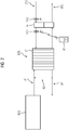
- FIG 1 shows a schematic side view of a rail vehicle, which is designed, for example, as a multiple unit TZ with a plurality of cars for passenger transport, with only a first car in the form of an end car EW and a second car coupled to this in the form of a middle car MW being shown as an example.
- a multiple unit usually has two end cars and a number of middle cars.
- a multiple unit can consist of only two end cars.
- the rail vehicle can be designed in the same way as a railcar or a locomotive.
- the end cars EW and middle cars MW shown each have a car body WK, which is supported by two bogies DG in the form of powered bogies or trailer bogies on rails of the route to be traveled, not shown.
- the rear right end of the end car EW and the front left end of the middle car MW can also be supported on a common bogie, in particular on a so-called Jakobs bogie.
- the end car EW is subdivided into several spatial areas with respect to the longitudinal axis L or horizontal axis.
- the middle car MW has only one passenger compartment FR.
- the passenger compartments FR of the cars EW, MW can be entered and exited by passengers via doors (not shown) arranged in the side walls of the respective car body WK. Furthermore, passengers can get into the passenger compartment of an adjacent car via a car transition.
- the exemplary TZ multiple unit has been prepared for operation on non-electrified or only partially electrified sections of the rail network. For this reason, the multiple unit TZ does not have a pantograph that can be connected to an overhead line on the network side, via which the multiple unit TZ can be supplied with electrical energy for its operation. Rather, the electrical energy required to operate the multiple unit TZ is generated by means of a fuel cell system BZS arranged on the vehicle.
- Mechanical and electrical main components of the fuel cell system BZS in particular a PEM fuel cell stack, a compressor, air filter and one or more humidifiers, according to the example FIG 1 arranged in a fuel cell container BZC on the roof of the end car EW of the multiple unit TZ.
- the fuel required for the operation of the fuel cell system BZS for example hydrogen
- a fuel storage device BSS which is also arranged on the roof of the end vehicle EW and is fluidically connected to the fuel cell container via suitable lines or pipes.
- an air conditioning container KC is arranged on the roof of the end car EW, in which, for example, both electrical and mechanical components for the air conditioning of the passenger compartment FR of the end car EW and components in particular for temperature control of components of the fuel cell system BZS are housed.
- a traction battery container TBC is provided for a traction battery that can be fed by the fuel cell system BZS via a DC voltage controller. Furthermore, in the underfloor area of the end car EW, a Converter container SRC provided for a traction converter, which is particularly connected to the traction battery and traction motors supplied with electrical energy.
- the traction motors are arranged, for example, in the bogies DG of the end car EW designed as motor bogies, with further traction motors being able to be arranged in further bogies of the multiple unit TZ, in particular depending on the required maximum drive power.
- containers listed and the systems and components arranged therein other components and devices that are not specifically shown but are required for the operation of the multiple unit, in particular devices for controlling the various systems and components, can be provided in or on the car body WK of the end car EW. It is also possible to distribute the various containers and components to several cars of the TZ multiple unit, in particular in order not to exceed the specified maximum wheel loads.
- the containers, systems and components listed can also be provided multiple times in the multiple unit TZ, in particular in order to increase the electrical energy that can be generated and thus the possible traction power.
- FIG 2 shows a schematic example of a fuel cell system BZS for the multiple unit TZ FIG 1 , which is designed to implement the method according to the invention.
- the central component of the fuel cell system BZS is a PEM fuel cell with a large number of membrane electrode units arranged in a stack ST and electrically connected in series.
- a power that can be generated by the fuel cell system BZS can be in the range of several hundred kilowatts, for example.
- the two reactants required for the electrochemical process, hydrogen and oxygen, are fed to the fuel cell stack ST.
- the anode side of the fuel cell stack ST is connected to the fuel store BSS via a first feed ZF1.
- a pressure control valve (not shown) arranged in this first feed ZF1 serves to set a desired pressure of the gaseous hydrogen.
- the hydrogen is supplied superstoichiometrically, ie more hydrogen is supplied to the fuel cell stack ST than it consumes.
- the hydrogen not consumed during the process is discharged as anode exhaust gas from the first feed ZF1 via a first discharge AF1 or fed back via a recirculation branch RZ connecting the first feed ZF1 and the first discharge AF1 and mixed with hydrogen flowing in.
- a water separator for separating water of reaction entering the anode waste gas
- a so-called purge valve for releasing nitrogen
- a pressure relief valve for protecting the fuel cell from excess pressure
- the cathode side of the fuel cell stack ST is supplied with oxygen-containing ambient air via a second supply ZF2.
- the air is sucked in from the environment of the multiple unit TZ via an electrically operated air compressor arranged in the second supply ZF2 and freed of particles and chemical compounds that could damage the membranes of the fuel cell stack ST or impair their function by means of one or more downstream air filters .
- Air compressor and air filter are again not shown separately.
- the oxygen is also supplied superstoichiometrically, so more oxygen is supplied to the fuel cell stack ST than it consumes.
- the Cathode waste gas is discharged to the environment via a second discharge AF2.
- a humidifier BF is arranged in the second feed ZF2 downstream of the one or more air filters.
- the humidification of the air serves to prevent the membranes of the fuel cell stack from drying out.
- the humidifier BF is designed as a gas/gas humidifier and is also arranged in the second outlet AF2 downstream of the fuel cell stack ST.
- the moist cathode exhaust gas that is present in the fuel cell stack ZF and is produced during the electrochemical process causes humidification of the cleaned air flowing through in the humidifier BF.
- the humidifier BF can be designed, for example, as a cocurrent or countercurrent humidifier.
- a pressure valve can also be provided, for example in the second inlet ZF2 or the second outlet AF2, which is also not shown.
- the humidifier in particular is subject to high mechanical loads during the driving operation of the rail vehicle, which are caused in particular by vibrations and impacts, and on the other hand loading of the membrane separating the air streams with particles and other contaminants, which also increases with loading of the or the upstream air filter are contained in the supplied air. Both mechanical damage and loading by particles and other contaminants lead to a reduction in the membrane's capacity to extract water from the cathode exhaust gas and to supply it to the drier supply air, and thus to a decrease in the humidification capacity of the humidifier BF.
- the condition-dependent cleaning or replacement takes place on the basis of a predetermined aging model, which is selected from a plurality of aging models defined for different operating conditions of the rail vehicle. According to the selected predetermined aging model, the maintenance personnel cleans the membrane in particular or completely replaces the humidifier BF.
- Such an activity requires direct access to the humidifier BF, which according to the above description to the FIG 1 is arranged as part of the main components of the fuel cell system BZS in the fuel cell container BZC on the roof of the end car EW of the multiple unit TZ.
- the cleaning or replacement of this difficult-to-access area of the TZ multiple unit means a great deal of work for the maintenance staff, while replacing the humidifier represents a significant cost factor over the service life of the rail vehicle, which is typically 30 years.
- an aging model which reflects the real operating conditions of the fuel cell system BZS as precisely as possible, a significant cost saving can be achieved compared to fixed intervals.
- the quality of the depiction of the actual reduction in humidification performance by the aging model should preferably be checked regularly in order to make an adjustment, for example to the date of the next maintenance of the fuel cell system BZS, at which the humidifier should also be cleaned or replaced, or a more suitable one Select aging model for humidifier BF.
- a closable opening VOE is provided in the second feed ZF2 downstream of the humidifier BF, in which a first humidity sensor FS1 can be temporarily arranged.
- the closable opening can have a thread or a bayonet lock that is compatible with a corresponding thread or lock of the first moisture sensor FS1.
- the closable opening is preferably accessible to maintenance personnel in such a way that the fuel cell container BZC does not have to be opened completely, so that the moisture sensor FS1 can be quickly installed and removed.
- an easily accessible, lockable maintenance flap can be provided in the fuel cell container BZC for this purpose.
- the first humidity sensor FS1 is designed to determine the humidity of the air flowing out of the humidifier BF. Since the humidity of the air depends in particular on the temperature, the first humidity sensor FS1 preferably additionally has a temperature sensor in order to also determine the temperature of the air, in particular the actual process temperature. If the humidity sensor and temperature sensor are not implemented in a common housing, a corresponding further closable opening in the second feed ZF2 can be provided for the temperature sensor, preferably near the closable opening for the humidity sensor.
- the moisture sensor has, for example, a thin-film polymer sensor system and is preferably designed to be heatable.
- a heatability of the humidity sensor is specifically in an environment with high Humidity, especially at over 80% relative humidity, makes sense because in such an environment condensation can lead to saturation of the humidity sensor.
- the relative humidity is reduced to a level below condensation.
- a relative humidity of the air can be determined from the humidity and temperature determined by means of the sensors.
- the humidification performance of the humidifier BF can be determined based on the determined humidity and with knowledge of the humidity of the ambient air. If part of the cathode exhaust gas in particular is returned to the second feed ZF2 via a recirculation branch, which is arranged in the second feed ZF2 upstream of the humidifier BF and in the second outlet AF2 downstream of the humidifier BF, a further closable opening should be provided in the second supply ZF2 may be provided downstream of the recirculation branch in order to also temporarily arrange a second humidity sensor FS2 in this, as exemplified in FIG FIG 2 is shown. Finally, the humidification capacity of the humidifier BF can be determined on the basis of the respectively determined humidity of the first and the second humidity sensor FS1 or FS2.
- the first humidity sensor FS1 and, if necessary, a temperature sensor and a second humidity sensor FS2 are installed by maintenance personnel on the closable openings provided in the second feed.
- the measurements are then carried out using the mounted sensors during operation of the fuel cell system and preferably over a predetermined period of time, which is defined in such a way that it is possible to determine the humidification capacity of the humidifier BF.
- the measurements of the first humidity sensor FS1 and, if available, the second humidity sensor FS2 and the Temperature sensor or these measurements each representing information transmitted during the period via a radio interface from the sensors to an evaluation device AE.
- This evaluation device AE can be, for example, an electronic hand-held device that provides the maintenance personnel with information that is generally required for carrying out maintenance specifically on the fuel cell system BZS or the rail vehicle.
- an exemplary hand-held device has an optical output unit in the form of a screen and at least one electronic processor and a data memory.
- the processor is used in particular to evaluate the information provided to the one or more sensors in order to derive a humidification performance and thus a current state of the humidifier BF from this.
- the humidification performance determined from the information provided can be compared with the expected humidification performance according to the aging model assigned and stored in the data memory of the evaluation device AE.
- the respective humidification performance can be displayed to the maintenance staff via the optical output unit.
- a difference between the determined humidification capacity and the humidification capacity expected according to the aging model can be determined in the evaluation device AE, for example, and compared with a predetermined threshold value.
- information can be output via the optical output unit as to whether the currently determined state of the humidifier corresponds to a state expected according to the aging model, a worse state or even a better state. Based on this information, the maintenance personnel can then carry out further activities, for example cleaning or replacing the humidifier in a worse condition, in a better condition for example, make an adjustment to the time of a next status determination.
- information can also be transmitted by cable.
- the sensors can alternatively also have a data memory in which information generated during the period of the measurements is stored. After the measurements have been completed, this stored information can be transmitted to the evaluation device AE and can in turn be evaluated there in accordance with the above description.
- the evaluation device AE can alternatively be configured as a stationary device, which is used, for example, for central detection and evaluation of the condition of various systems and components of the rail vehicle in order to coordinate necessary maintenance activities on the vehicle based on this.
- the evaluation device AE can also be designed as part of a control device of the fuel cell system BZS, which, in addition to the control, also serves to centrally record the states of at least some of the components of the fuel cell system.
- FIG 3 shows schematically an example of an alternative fuel cell system BZS, which according to the example of FIG 2 is configured to implement the method according to the invention.
- this alternative fuel cell system BZS are instead of a single humidifier BF, as in the example of FIG 2 specified, three humidifiers BF are arranged in the second supply ZF2 and the second discharge AF2 in order to achieve a higher humidification performance.
- a different number of humidifiers BF be provided.
- the three humidifiers BF given by way of example are connected in parallel, with both the air flow in the second feed ZF2 and the cathode exhaust gas in the second outlet AF2 being divided into three partial flows upstream of the humidifier BF and the respective partial flows being divided back into a common one downstream of the humidifier BF stream are merged.
- a closable opening VOE is provided downstream of the respective humidifier BF and before the partial flows are combined in the partial branch of the second supply ZF2 for the installation of a first humidity sensor FS1.
- further closable openings can be provided for installing a second humidity sensor FS2 and a temperature sensor, with these further openings being arranged in the second supply ZF2, outside the sub-branches for the three humidifiers BF.
- a first humidity sensor FS1 is used to sequentially determine a respective humidification capacity of the three humidifiers BF.
- the maintenance personnel successively mount the first humidity sensor FS1 on the closable opening VOE of the sub-branch downstream of one of the three humidifiers BF and leave it there during the specified period for the humidity measurements.
- the humidification performance and thus the state of each of the three humidifiers BF can be determined, so that based on this, if necessary, different measures can be taken, in particular with regard to cleaning or replacement by the maintenance personnel.
- three first humidity sensors FS1 can also be used in order to enable the state of the humidifier to be determined in parallel and therefore more quickly.
- the status of the humidifier BF is determined without installing a second humidity sensor FS2 on the provided one closable opening VOE.
- the recirculation branch between the second outlet AF2 and the second inlet ZF2 is closed by means of a valve arranged in the branch, so that the cathode exhaust gas is completely fed to the environment and consequently the air supplied is not mixed with the cathode exhaust gas upstream of the humidifier BF .
Abstract
Ein in einem Schienenfahrzeug eingesetztes Brennstoffzellensystem weist zumindest einen PEM-Brennstoffzellenstapel, eine erste Zuführung, welche dazu ausgestaltet ist, Wasserstoff als Brenngas einer Anodenseite des Brennstoffzellenstapels zuzuführen, eine zweite Zuführung, welche dazu ausgestaltet ist, Luft als Oxidationsgas einer Kathodenseite des Brennstoffzellenstapels zuzuführen, sowie zumindest einen Befeuchter, welcher in der zweiten Zuführung angeordnet ist und dazu ausgestaltet ist, dem Brennstoffzellenstapel zugeführte Luft zu befeuchten, auf. Erfindungsgemäß wird eine Reinigung und/oder ein Austausch des zumindest einen Befeuchters abhängig von einem vorgegebenen Alterungsmodell durchgeführt.A fuel cell system used in a rail vehicle has at least one PEM fuel cell stack, a first supply, which is designed to supply hydrogen as fuel gas to an anode side of the fuel cell stack, a second supply, which is designed to supply air as oxidizing gas to a cathode side of the fuel cell stack, and at least one humidifier, which is arranged in the second feed and is designed to humidify the air fed to the fuel cell stack. According to the invention, the at least one humidifier is cleaned and/or replaced depending on a predefined aging model.
Description
Die Erfindung betrifft ein Verfahren zum Betreiben eines Brennstoffzellensystems in einem Schienenfahrzeug, wobei das Brennstoffzellensystem zumindest einen Befeuchter aufweist.The invention relates to a method for operating a fuel cell system in a rail vehicle, the fuel cell system having at least one humidifier.
Insbesondere im Regional- und Fernverkehr werden Schienenfahrzeuge vorzugsweise mittels einer Oberleitung oder Stromschiene mit elektrischer Energie versorgt. Es existieren üblicherweise jedoch weiterhin Strecken bzw. Streckenabschnitte des Schienennetzes, welche nicht mit einer solchen Infrastruktur ausgerüstet sind. Beispielsweise sind aktuell in der Bundesrepublik Deutschland lediglich ca. 60% des Schienennetzes elektrifiziert. Auf nicht- oder teilelektrifizierten Strecken bzw. Streckenabschnitten werden daher weiterhin Schienenfahrzeuge eingesetzt, welche die für den Antrieb bzw. die Traktion und den Betrieb von Nebenverbrauchern bzw. so genannten Hilfsbetrieben erforderliche Energie mittels Verbrennungskraftmaschinen generieren.Particularly in regional and long-distance transport, rail vehicles are preferably supplied with electrical energy by means of an overhead line or power rail. However, there are usually still routes or route sections of the rail network that are not equipped with such an infrastructure. For example, only about 60% of the rail network in the Federal Republic of Germany is currently electrified. On non- or partially electrified routes or route sections, rail vehicles are therefore still used, which generate the energy required for the drive or traction and the operation of auxiliary consumers or so-called auxiliary systems by means of internal combustion engines.
Um einen im Vergleich zu solchen mit Verbrennungskraftmaschinen betriebenen Schienenfahrzeugen umweltfreundlicheren Betrieb auf solchen Strecken bzw. Streckenabschnitten zu ermöglichen, werden Schienenfahrzeuge zunehmend mit elektrischen Energiespeichern, so genannten Traktionsbatterien, ausgerüstet. Abhängig von einer in den elektrischen Energiespeichern speicherbaren Energiemenge können diese Schienenfahrzeuge eine bestimmte Distanz ohne eine Versorgung über eine Oberleitung zurücklegen. Die Energiespeicher werden bei Befahren elektrifizierter Streckenabschnitte bzw. während eines Halts über eine beispielsweise im Bereich von Haltestellen angeordnete geeignete Ladeinfrastruktur wieder mit elektrischer Energie geladen. Ein Einsatz solcher Energiespeicher eignet sich insbesondere für den Regionalverkehr kürzeren Distanzen zwischen Haltestellen.In order to enable more environmentally friendly operation on such routes or route sections than rail vehicles operated with internal combustion engines, rail vehicles are increasingly being equipped with electrical energy stores, so-called traction batteries. Depending on the amount of energy that can be stored in the electrical energy stores, these rail vehicles can cover a certain distance without being supplied via an overhead line. The energy stores are recharged with electrical energy when driving on electrified route sections or during a stop via a suitable charging infrastructure arranged, for example, in the area of stops. The use of such an energy store is suitable especially for regional transport shorter distances between stops.
Für den Einsatz im weiteren Regionalverkehr sowie Fernverkehr mit üblicherweise größeren Distanzen zwischen Haltestellen ist die Ausrüstung von Schienenfahrzeugen mit elektrischen Energiespeichern hingegen weniger geeignet, da die in diesen speicherbare elektrische Energie zu gering ist bzw. Gewicht und Ausmaße der hierfür erforderlichen Energiespeicher die Kapazität des Schienenfahrzeugs übersteigen würden.On the other hand, equipping rail vehicles with electrical energy storage systems is less suitable for use in further regional transport and long-distance transport with usually longer distances between stops, since the electrical energy that can be stored in these is too low or the weight and dimensions of the energy storage systems required for this exceed the capacity of the rail vehicle would.
Insbesondere im Fernverkehr wird als Alternative zu Traktionsbatterien der Einsatz von Brennstoffzellen als sinnvoll erachtet. Diese generieren mittels eines elektro-chemischen Prozesses aus einem Brennstoff elektrische Energie, mittels welcher Traktionseinrichtungen und Hilfsbetriebe des Schienenfahrzeugs betrieben werden können. Ergänzend zu der eigentlichen Brennstoffzelle und deren Hilfsbetrieben sind hierfür insbesondere ein Brennstoffspeicher sowie ein elektrischer Energiespeicher erforderlich, wobei der elektrische Energiespeicher eine im Vergleich zu einer Traktionsbatterie deutlich geringere Speicherkapazität aufweisen kann, da dieser vorwiegend der Versorgung der Hilfsbetriebe der Brennstoffzelle, insbesondere während der Inbetriebnahme der Brennstoffzelle, sowie als Pufferspeicher dem Ausgleich kurzzeitiger Lastschwankungen dient.The use of fuel cells is considered a sensible alternative to traction batteries, particularly in long-distance transport. Using an electro-chemical process, these generate electrical energy from a fuel, by means of which traction devices and auxiliary systems of the rail vehicle can be operated. In addition to the actual fuel cell and its auxiliaries, a fuel storage device and an electrical energy storage device are required for this purpose, whereby the electrical energy storage device can have a significantly lower storage capacity compared to a traction battery, since this is primarily used to supply the fuel cell's auxiliaries, especially during the commissioning of the Fuel cell, as well as a buffer storage to compensate for short-term load fluctuations.
Als besonders geeignet für den Einsatz in Schienenfahrzeugen wird eine Membran-Brennstoffzelle, bekannt unter den Begriffen Protonenaustauschmembran-Brennstoffzelle (Engl. Proton Exchange Membrane Fuel Cell, PEMFC) bzw. Polymer-Elektrolyt-Brennstoffzelle (Engl. Polymer Electrolyte Fuel Cell, PEFC), angesehen, da diese sowohl schnelle Lastwechsel zulässt als auch mit Lastwechseln verbundene Temperaturschwankungen im Vergleich zu anderen bekannten Brennstoffzellentypen gut kompensieren kann. Nachfolgend wird dieser Brennstoffzellentyp als PEM-Brennstoffzelle bezeichnet. Die Arbeitstemperatur einer PEM-Brennstoffzelle liegt unterhalb von 100°C, typischerweise im Bereich zwischen 60°C und 80°C, weshalb sie der Gruppe der Niedertemperatur-Brennstoffzellen mit Betriebstemperaturen zwischen 60°C und 130°C zugeordnet ist. Brennstoffzellentypen werden nach dem jeweils verwendeten Elektrolyten unterschieden.A membrane fuel cell, known as a proton exchange membrane fuel cell (PEMFC) or a polymer electrolyte fuel cell (PEFC), is particularly suitable for use in rail vehicles. considered, since this both allows rapid load changes and can also compensate well for temperature fluctuations associated with load changes in comparison to other known fuel cell types. This type of fuel cell is referred to below as a PEM fuel cell designated. The working temperature of a PEM fuel cell is below 100°C, typically in the range between 60°C and 80°C, which is why it is assigned to the group of low-temperature fuel cells with operating temperatures between 60°C and 130°C. Fuel cell types are differentiated according to the electrolyte used.
In einer PEM-Brennstoffzelle übernimmt eine dünne, gasdichte und protonenleitende Kunststofffolie die Funktion des Elektrolyten und wirkt als Separator für die gasförmigen Reaktanten Wasserstoff (als Brenngas) und Sauerstoff (als Oxidationsgas), wobei letzterer der Brennstoffzelle als Bestandteil der Umgebungsluft zugeführt wird. Die zentrale Membran-Elektroden-Einheit (Engl. Membrane Electrode Assembly, MEA) ist das aktive Element der Brennstoffzelle. Diese besteht aus zwei durch den Elektrolyten voneinander getrennten Elektroden, einer Anode und einer Kathode, und ist beidseitig jeweils mit einem Gasverteiler und einem Stromableiter kontaktiert, wobei die Gasverteiler einer Gaszufuhr und Gasabfuhr dienen. Eine PEM-Brennstoffzelle wird durch eine Vielzahl in einem Stapel (Engl. Stack) angeordneter MEA gebildet, die elektrisch in Reihe geschaltet sind, um eine höhere Spannung und damit eine höhere mögliche Leistung der Brennstoffzelle zu erzielen.In a PEM fuel cell, a thin, gas-tight and proton-conducting plastic film assumes the function of the electrolyte and acts as a separator for the gaseous reactants hydrogen (as fuel gas) and oxygen (as oxidation gas), with the latter being fed to the fuel cell as part of the ambient air. The central membrane electrode assembly (MEA) is the active element of the fuel cell. This consists of two electrodes separated from one another by the electrolyte, an anode and a cathode, and is contacted on both sides with a gas distributor and a current conductor, with the gas distributors serving to supply and discharge gas. A PEM fuel cell is formed by a large number of MEAs arranged in a stack, which are electrically connected in series in order to achieve a higher voltage and thus a higher possible output of the fuel cell.
Bei Zuführung von Wasserstoff zu der Anode und Sauerstoff zu der Kathode entsteht zwischen den beiden Elektroden eine Potenzialdifferenz. An der Anode oxidiert der Wasserstoff und es entstehen Wasserstoffionen bzw. Protonen, die durch die protonenleitende Membran zu der Kathode wandern. Die Membran stellt für die Elektronen hingegen ein Isolator dar, weshalb diese über einen äußeren Stromkreis, in welchen eine Last geschaltet ist, von der Anode zur Kathode transportiert werden, wodurch der elektrische Stromkreis geschlossen wird. An der Kathode reagieren die Wasserstoffionen mit dem Sauerstoff der Luft und als Reaktionsprodukt entsteht Wasser, auch als Reaktionswasser bzw. Produktwasser bezeichnet.When hydrogen is supplied to the anode and oxygen is supplied to the cathode, a potential difference arises between the two electrodes. The hydrogen oxidizes at the anode and hydrogen ions or protons are formed, which migrate through the proton-conducting membrane to the cathode. The membrane, on the other hand, represents an insulator for the electrons, which is why these are transported from the anode to the cathode via an external circuit in which a load is connected, which closes the electrical circuit. At the cathode, the hydrogen ions react with the oxygen in the air and the reaction product is water, also known as reaction water or product water.
Eine besondere Herausforderung beim Betrieb einer PEM-Brennstoffzelle stellt das so genannte Wassermanagement dar. Die Protonenleitfähigkeit der Membran ist insbesondere von dem Wassergehalt bzw. von der Feuchte der Membran, welcher bzw. welche von Faktoren wie der Stromdichte, der Feuchte der Reaktanten sowie der Temperatur beeinflusst wird. Eine zu geringe Feuchte der Membran führt zu einer reduzierten Protonenleitfähigkeit und damit zu einer Verringerung der Leistung sowie schließlich zu einer Degradation der Brennstoffzelle. Eine Flutung der Kathode mit Reaktionswasser hingegen kann zu einer Blockierung von Kanälen des kathodenseitigen Gasverteilers führen, wodurch die Funktion der Zelle ebenfalls eingeschränkt wird. Für den effizienten Betrieb der PEM-Brennstoffzelle ist es daher von Bedeutung, dass einerseits ausreichend Wasser in der Zelle verbleibt, andererseits eine exzessive Bildung von Reaktionswasser vermieden wird.A particular challenge when operating a PEM fuel cell is the so-called water management. The proton conductivity of the membrane depends in particular on the water content or the moisture content of the membrane, which factors such as the current density, the moisture content of the reactants and the temperature being affected. Insufficient membrane humidity leads to reduced proton conductivity and thus to a reduction in performance and ultimately to degradation of the fuel cell. Flooding the cathode with water of reaction, on the other hand, can lead to the channels of the gas distributor on the cathode side being blocked, which also restricts the function of the cell. For the efficient operation of the PEM fuel cell, it is therefore important that on the one hand sufficient water remains in the cell and on the other hand an excessive formation of reaction water is avoided.
Insbesondere in Brennstoffzellensystemen höherer Leistung, wie sie in Schienenfahrzeugen eingesetzt werden sollen, wird eine ausreichende Feuchte der Membran durch Einsatz zusätzlicher Befeuchter zur Befeuchtung der Reaktanten stromaufwärts der Brennstoffzelle sichergestellt. Für PEM-Brennstoffzellen niedrigerer Leistung ist ein Einsatz zusätzlicher Befeuchter hingegen üblicherweise nicht erforderlich.In particular in fuel cell systems of higher power, such as those to be used in rail vehicles, sufficient humidity of the membrane is ensured by using additional humidifiers for humidifying the reactants upstream of the fuel cell. For PEM fuel cells of lower power, on the other hand, the use of additional humidifiers is usually not necessary.
Bekannte Befeuchter sind ähnlich einem Wärmetauscher aufgebaut, wobei beispielsweise eine Vielzahl von Röhrchen aus einem Membranmaterial oder eine flächige Membran, insbesondere eine hydrophile Polymermembran, den zu befeuchtenden Reaktanten von einem Befeuchtergas bzw. von Wasser trennt. Unterschieden wird dabei zwischen einem so genannten Gas/Gas-Befeuchter, in welchem ein Befeuchtergas mit einer hohen Feuchte bzw. Wasserdampfkonzentration zur Befeuchtung des Reaktanten dient, und einem so genannten Wasser/Gas-Befeuchter, in welchem durch den Befeuchter zirkulierendes Wasser der Befeuchtung des Reaktanten dient. In Gas/Gas-Befeuchtern bewirken Ionenkanäle der Membran, dass Wasser aus dem Befeuchtergas gebunden, in Richtung des Partialdruckgefälles transportiert und von dem trockeneren Reaktanten aufgenommen wird. Als Befeuchtergas ist insbesondere das Kathodenabgas der Brennstoffzelle verwendbar, welches aufgrund des kathodenseitig anfallenden Reaktionswassers eine hohe Feuchte aufweist. Vorteilhaft ist dieses einerseits bereits energieneutral in dem Brennstoffzellensystem verfügbar, andererseits wird zusammen mit der Feuchte auch dessen Wärme auf den Reaktanten übertragen.Known humidifiers are constructed similarly to a heat exchanger, with, for example, a large number of tubes made of a membrane material or a flat membrane, in particular a hydrophilic polymer membrane, separating the reactant to be humidified from a humidifier gas or from water. A distinction is made between a so-called gas/gas humidifier, in which a humidifier gas with a high humidity or water vapor concentration is used to humidify the reactant, and a so-called water/gas humidifier, in which water circulating through the humidifier is used to humidify the reactants serves. In gas-to-gas humidifiers, membrane ion channels cause water to be bound from the humidifier gas, transported down the partial pressure gradient, and taken up by the drier reactant. In particular, the cathode exhaust gas of the fuel cell can be used as the humidifier gas, which has a high moisture content due to the water of reaction occurring on the cathode side. On the one hand, this is advantageously already available in an energy-neutral manner in the fuel cell system, on the other hand, its heat is also transferred to the reactants together with the moisture.
Die Membranen der Befeuchter sind bei einem Einsatz in Schienenfahrzeugen einerseits hohen mechanischen Belastungen, insbesondere hervorgerufen durch Vibrationen und Stöße, andererseits einer Beladung durch Partikel und anderen Kontaminanten wie beispielsweise Salze, Stickoxide oder Verbundstoffe mit Schwefel oder Ammoniak ausgesetzt, welche trotz dem Befeuchter in der Zuführung vorgeschalteter Luftfilter, insbesondere wenn diese stärker oder vollständig mit Kontaminanten beladen sind, in der zugeführten Luft enthalten sind. Solche Partikel und Kontaminanten führen zu einer Verringerung des Wassertransports durch die Membran und damit zu einer Verringerung der Befeuchtungsleistung des Befeuchters.When used in rail vehicles, the membranes of the humidifier are on the one hand exposed to high mechanical loads, in particular caused by vibrations and impacts, and on the other hand to a load of particles and other contaminants such as salts, nitrogen oxides or compounds with sulfur or ammonia, which despite the humidifier in the supply upstream air filters, especially if they are heavily or completely loaded with contaminants, are contained in the supplied air. Such particles and contaminants lead to a reduction in the transport of water through the membrane and thus to a reduction in the humidification capacity of the humidifier.
Zur Sicherstellung einer effizienten Funktion des einen bzw. der mehreren Befeuchter und damit der Funktion der PEM-Brennstoffzelle während des Betriebs in einem Schienenfahrzeug muss dessen bzw. deren Membran daher regelmäßig gereinigt bzw. bei Beschädigung getauscht werden. Ein solcher Tausch kann auf Basis eines festen Tauschintervalls zwischen 5.000 und 10.000 Betriebsstunden, welches beispielsweise herstellerseitig für bekannte Befeuchter empfohlen wird, erfolgen. Dieses bedeutet jedoch nachteilig, dass über den Einsatzzeitraum eines Schienenfahrzeugs von typischerweise 30 Jahren hohe Betriebskosten bereits für die Aufrechterhaltung der Funktion des bzw. der Befeuchter des Brennstoffzellensystems entstehen.To ensure efficient functioning of the one or more humidifiers and thus the functioning of the PEM fuel cell during operation in a rail vehicle, its or their membrane must therefore be cleaned regularly or replaced if damaged. Such an exchange can take place on the basis of a fixed exchange interval between 5,000 and 10,000 operating hours, which is recommended by the manufacturer for known humidifiers, for example. However, this has the disadvantage that over the period of use of a rail vehicle, which is typically 30 years, high Operating costs already arise for maintaining the function of the humidifier or the fuel cell system.
Aufgabe der Erfindung ist es daher, ein Verfahren zum Betreiben eines Brennstoffzellensystems für ein Schienenfahrzeug anzugeben, welches insbesondere eine Verringerung der Betriebskosten im Zusammenhang mit eingesetzten Befeuchtern ermöglicht. Diese Aufgabe wird durch das Verfahren mit den Merkmalen des unabhängigen Patentanspruchs gelöst. Weiterbildungen der Erfindung sind in abhängigen Patentansprüchen angegeben.The object of the invention is therefore to specify a method for operating a fuel cell system for a rail vehicle, which in particular enables a reduction in operating costs in connection with humidifiers used. This object is solved by the method with the features of the independent patent claim. Developments of the invention are specified in the dependent patent claims.
Ein in einem Schienenfahrzeug eingesetztes Brennstoffzellensystem weist zumindest einen PEM-Brennstoffzellenstapel, eine erste Zuführung, welche dazu ausgestaltet ist, Wasserstoff als Brenngas einer Anodenseite des Brennstoffzellenstapels zuzuführen, eine zweite Zuführung, welche dazu ausgestaltet ist, Luft als Oxidationsgas einer Kathodenseite des Brennstoffzellenstapels zuzuführen, sowie zumindest einen Befeuchter, welcher in der zweiten Zuführung angeordnet ist und dazu ausgestaltet ist, dem Brennstoffzellenstapel zugeführte Luft zu befeuchten, auf. Erfindungsgemäß wird eine Reinigung und/oder ein Austausch des zumindest einen Befeuchters abhängig von einem vorgegebenen Alterungsmodell durchgeführt.A fuel cell system used in a rail vehicle has at least one PEM fuel cell stack, a first supply, which is designed to supply hydrogen as fuel gas to an anode side of the fuel cell stack, a second supply, which is designed to supply air as oxidizing gas to a cathode side of the fuel cell stack, and at least one humidifier, which is arranged in the second feed and is designed to humidify the air fed to the fuel cell stack. According to the invention, the at least one humidifier is cleaned and/or replaced depending on a predefined aging model.
Erfindungsgemäß wurde erkannt, dass aufgrund einer Durchführung einer Reinigung und/oder eines Austauschs des zumindest einen Befeuchters auf Basis eines Alterungsmodells der PEM-Brennstoffzellenstapel vorteilhaft einerseits mit einer hohen Effizienz bei langer Betriebsdauer betreibbar ist, andererseits Kosten für Ersatz und Arbeitskosten, welche insbesondere aufgrund von eine jeweilige Demontage des Befeuchters erfordernden Sichtprüfungen und Reinigungsarbeiten durch Wartungspersonal entstehen, gegenüber vorgegebenen festen Zeitintervallen vorteilhaft deutlich verringert werden können. Besonders ausgeprägt können diese Vorteile verwirklicht werden, wenn eine die Betriebsbedingungen des Schienenfahrzeugs und damit des Brennstoffzellensystems bekannt sind, sodass das Alterungsmodell entsprechend diesen Bedingungen definiert werden kann.According to the invention, it was recognized that by carrying out cleaning and/or replacing the at least one humidifier based on an aging model, the PEM fuel cell stack can advantageously be operated with high efficiency over a long service life on the one hand, and on the other hand costs for replacement and labor costs, which in particular are due to a respective disassembly of the humidifier requiring visual inspections and cleaning work by maintenance personnel can advantageously be significantly reduced compared to predetermined fixed time intervals. Particularly pronounced these advantages can be realized if one knows the operating conditions of the rail vehicle and thus of the fuel cell system, so that the aging model can be defined according to these conditions.
Ein Alterungsmodell definiert eine erwartete Verringerung der Befeuchtungsleistung des Befeuchters über der Zeit und in Abhängigkeit von den Betriebsbedingungen des Schienenfahrzeugs. Betriebsbedingungen betreffen insbesondere herrschende Umgebungs- bzw. Umweltbedingungen auf der von dem Schienenfahrzeug zu befahrenden Strecke. Umgebungs- bzw. Umweltbedingungen sind beispielsweise Belastungen der Umgebungsluft mit Partikeln sowie bestimmten chemische Verbindungen, welche als Kontaminanten wirkend die Funktion der Befeuchtungsmembran und damit die Befeuchtungsleistung des Befeuchters beeinträchtigen können. Insbesondere sind beispielsweise die Belastungen in Städten und Industrieregionen und jene in Gebieten mit landwirtschaftlicher Nutzung unterschiedlich. Da derartige Belastungen insbesondere temporär auftreten, sollte das Alterungsmodell vorzugsweise auch temporäre Änderungen der Umgebungs- bzw. Umweltbedingungen, insbesondere jahreszeitabhängige Änderungen, berücksichtigen. Weiterhin betreffen die Betriebsbedingungen beispielsweise auf den Befeuchter bzw. auf die Befeuchtungsmembran wirkende mechanische Belastungen, welche mechanische Schädigungen und damit ebenfalls eine Verringerung der Befeuchtungsleistung bewirken können.An aging model defines an expected reduction in the humidification performance of the humidifier over time and depending on the operating conditions of the rail vehicle. Operating conditions relate in particular to prevailing ambient or environmental conditions on the route to be traveled by the rail vehicle. Ambient or environmental conditions are, for example, contamination of the ambient air with particles and certain chemical compounds which, acting as contaminants, can impair the function of the humidifying membrane and thus the humidifying performance of the humidifier. In particular, for example, the loads in cities and industrial regions and those in areas with agricultural use are different. Since such loads occur particularly temporarily, the aging model should preferably also take into account temporary changes in the ambient or environmental conditions, in particular seasonal changes. Furthermore, the operating conditions relate, for example, to mechanical loads acting on the humidifier or on the humidifying membrane, which can cause mechanical damage and thus also a reduction in the humidifying capacity.
Verschiedene Alterungsmodelle können definiert werden, welche jeweils unterschiedliche Betriebsbedingungen berücksichtigen. Entsprechend wird beispielsweise ein Alterungsmodell ausgewählt, welches auf Betriebsbedingungen basierend definiert wurde, die mit denen der von dem Schienenfahrzeug befahrenen Strecke weitgehend übereinstimmen, sodass vorteilhaft Reinigungsarbeiten bzw. ein Austausch des bzw. der in dem Schienenfahrzeug eingesetzten Befeuchter zustandsabhängig durchgeführt werden kann. Sollten während des Betriebs des Schienenfahrzeugs größere Abweichungen des tatsächlichen Zustands von dem gemäß dem Alterungsmodell erwarteten Zustand des zumindest einen Befeuchters festgestellt werden, so kann eine entsprechende Anpassung des Alterungsmodells erfolgen bzw. ein anderes, die Betriebsbedingungen genauer widerspiegelndes Alterungsmodell gewählt werden.Various aging models can be defined, each of which takes different operating conditions into account. Accordingly, an aging model is selected, for example, which was defined based on operating conditions that largely match those of the route traveled by the rail vehicle, so that cleaning work or replacement of the humidifier(s) used in the rail vehicle is advantageous can be performed conditionally. If, during operation of the rail vehicle, the actual state deviates significantly from the state of the at least one humidifier expected according to the aging model, the aging model can be adjusted accordingly or another aging model that more accurately reflects the operating conditions can be selected.
Zur Erzielung der erforderlichen Befeuchtungsleistung können ein einziger oder mehrere Befeuchter vorgesehen sein. Die mehreren Befeuchter können dabei parallel angeordnet sein, wobei durch jeden Befeuchter nur ein Teilstrom der Luft geführt wird und die Teilströme stromabwärts der Befeuchter vorzugsweise wieder zusammengeführt werden, oder seriell angeordnet sein, wobei in jedem der Befeuchter eine Teilbefeuchtung der Luft erfolgt.A single humidifier or several humidifiers can be provided to achieve the required humidification performance. The several humidifiers can be arranged in parallel, with only a partial flow of the air being passed through each humidifier and the partial flows are preferably combined again downstream of the humidifier, or arranged in series, with partial humidification of the air taking place in each of the humidifiers.
Gemäß einer Weiterbildung der Erfindung weist das Brennstoffzellensystem ferner zumindest einen Feuchtesensor auf, welcher ausschließlich temporär in der zweiten Zuführung stromabwärts des zumindest einen Befeuchters angeordnet wird, wobei mittels des zumindest einen Feuchtesensors eine Feuchte der dem Brennstoffzellenstapel zugeführten Luft bestimmt wird.According to a further development of the invention, the fuel cell system also has at least one humidity sensor, which is arranged exclusively temporarily in the second inlet downstream of the at least one humidifier, with the at least one humidity sensor determining the humidity of the air supplied to the fuel cell stack.
Das Brennstoffzellensystem in dem Schienenfahrzeug sieht bewusst von einer aktiven Steuerung des Befeuchtungsgrads der dem Brennstoffzellenstapel zugeführten Luft ab, wie sie insbesondere in Kraftfahrzeugen mit einer Brennstoffzelle eingesetzt wird. In diesen wird mittels einer parallel zum Befeuchter angeordneten Bypass-Leitung, einem steuerbaren Bypass-Ventil sowie einem Feuchtesensor die Feuchte des kathodenseitigen Reaktanten gesteuert. Die vorteilhafte Wirkung einer solchen Steuerung, insbesondere bei Anordnung des Befeuchters entfernt von dem Brennstoffzellenstapel, konnte bislang nicht nachgewiesen werden, zudem stellen die genannten zusätzlichen Komponenten wiederum jeweils potenzielle Fehlerquellen für die Funktion des Brennstoffzellensystems dar. Der zumindest eine Befeuchter des Brennstoffzellensystems, in welchem das erfindungsgemäße Verfahren Anwendung findet, ist bezüglich der Befeuchtungsleistung beispielsweise derart dimensioniert, dass die Feuchte des kathodenseitigen Reaktanten im Bereich zwischen 80% und 95% liegt. Die Möglichkeit eines Ausgleichs einer über die Zeit geringer werdenden Befeuchtungsleistung des Befeuchters durch Ansteuerung eines Bypass-Ventils ist in dem Brennstoffzellensystem somit nicht vorgesehen.The fuel cell system in the rail vehicle deliberately refrains from actively controlling the degree of humidification of the air supplied to the fuel cell stack, as is used in particular in motor vehicles with a fuel cell. In these, the humidity of the cathode-side reactant is controlled by means of a bypass line arranged parallel to the humidifier, a controllable bypass valve and a humidity sensor. The advantageous effect of such a control, in particular when the humidifier is arranged at a distance from the fuel cell stack, has not yet been able to be proven potential sources of error for the function of the fuel cell system. The at least one humidifier of the fuel cell system in which the method according to the invention is used is dimensioned with regard to the humidification capacity such that the humidity of the cathode-side reactant is in the range between 80% and 95%. The possibility of compensating for a humidification capacity of the humidifier that decreases over time by controlling a bypass valve is therefore not provided in the fuel cell system.
Erfindungsgemäß wird der zumindest eine Feuchtesensor ausschließlich temporär in der zweiten Zuführung angeordnet, um eine aktuelle Feuchte der dem Brennstoffzellenstapel kathodenseitig zugeführten Luft zu bestimmen. Diese temporäre Anordnung und Bestimmung erfolgt beispielsweise während einer Außerbetriebsetzung des Schienenfahrzeugs, also während das Schienenfahrzeug nicht für den Personen- oder Gütertransport eingesetzt wird. Eine solche Außerbetriebsetzung erfolgt beispielsweise regelmäßig zur Wartung weiterer Komponenten und Einrichtungen des Schienenfahrzeugs sowie insbesondere zu Reinigungszwecken. Für die Bestimmung der Feuchte der zugeführten Luft mittels des zumindest einen Feuchtesensors ohne Demontage des zumindest einen Befeuchters ist ein Betrieb des Brennstoffzellensystems des Schienenfahrzeugs erforderlich.According to the invention, the at least one humidity sensor is arranged exclusively temporarily in the second feed, in order to determine a current humidity of the air fed to the fuel cell stack on the cathode side. This temporary arrangement and determination takes place, for example, while the rail vehicle is being taken out of service, ie while the rail vehicle is not being used to transport people or goods. Such decommissioning takes place, for example, regularly for the maintenance of other components and devices of the rail vehicle and, in particular, for cleaning purposes. In order to determine the humidity of the supplied air using the at least one humidity sensor without removing the at least one humidifier, it is necessary to operate the fuel cell system of the rail vehicle.
Hierzu wird der Feuchtesensor an einer für dessen Montage vorgesehenen Stelle der zweiten Zuführung von Wartungspersonal montiert. Hierfür kann beispielsweise eine verschließbare Öffnung in der zweiten Zuführungen vorgesehen sein, welche während des normalen Betriebs des Schienenfahrzeugs verschlossen ist, während Wartungsarbeiten jedoch von Wartungspersonal geöffnet werden kann, um einen Feuchtesensor in die zweite Zuführung zur Durchführung von Messungen einzuführen. Vorzugsweise weist der zumindest eine Feuchtesensor ergänzend einen Temperatursensor auf bzw. ist mit diesem in einem gemeinsamen Gehäuse angeordnet, wobei ein Temperatursensor auch getrennt von dem Feuchtesensor in der zweiten Zuführung angeordnet werden kann.For this purpose, the moisture sensor is installed by maintenance personnel at a point provided for its installation on the second feed. For this purpose, for example, a closable opening can be provided in the second supply, which is closed during normal operation of the rail vehicle but can be opened by maintenance personnel during maintenance work in order to introduce a moisture sensor into the second supply to carry out measurements. Preferably, the at least one humidity sensor also has a temperature sensor or is arranged with it in a common housing, with a Temperature sensor can also be arranged separately from the humidity sensor in the second feed.
Der Feuchtesensor ist beispielsweise mit einer Auswerteeinrichtung, insbesondere einem geeigneten elektronischen Handgerät des Wartungspersonals, einer Steuereinrichtung des Brennstoffzellensystems oder einer Steuereinrichtung des Schienenfahrzeugs kommunikationstechnisch verbunden. Eine Auswerteeinrichtung dient insbesondere dazu, basierend auf den von dem Feuchtesensor sowie insbesondere dem Temperatursensor bereitgestellten Informationen eine aktuelle Befeuchtungsleistung des Befeuchters zu bestimmen. Die bestimmte Befeuchtungsleistung wird von der Auswerteeinrichtung anschließend mit einer für den Zeitpunkt der Bestimmung erwarteten Befeuchtungsleistung gemäß dem Alterungsmodells verglichen, welches beispielsweise in einem Speicherbereich der Auswerteeinrichtung hinterlegt ist.The moisture sensor is connected in terms of communication, for example, to an evaluation device, in particular a suitable electronic hand-held device of the maintenance personnel, a control device of the fuel cell system or a control device of the rail vehicle. An evaluation device is used in particular to determine a current humidification performance of the humidifier based on the information provided by the humidity sensor and in particular the temperature sensor. The humidification performance determined is then compared by the evaluation device with a humidification performance expected for the time of determination according to the aging model, which is stored, for example, in a memory area of the evaluation device.
Sofern dieser Vergleich ergibt, dass die bestimmte Befeuchtungsleistung der erwarteten entspricht bzw. innerhalb eines vorgegebenen Toleranzbands um die erwartete Befeuchtungsleistung liegt, erfolgt beispielsweise eine Ausgabe einer entsprechenden Information über den Zustand des Befeuchters an das Wartungspersonal durch die Auswerteeinrichtung. Ergibt der Vergleich hingegen, dass die bestimmte Befeuchtungsleistung außerhalb des Toleranzbandes liegt, kann ein entsprechender Hinweis auf eine erforderliche Anpassung des Zeitpunkts einer nächsten Reinigung des Befeuchters bzw. eines Austausches von der Auswerteeinrichtung oder einer mit dieser verbundenen optischen und/oder akustischen Ausgabeeinrichtung ausgegeben werden. Insbesondere wenn die bestimmte Befeuchtungsleistung die erwartete Befeuchtungsleistung übersteigt, kann eine Reinigung bzw. ein erforderlicher Austausch des Befeuchters vorteilhaft erst zu einem späteren Zeitpunkt als nach dem Alterungsmodell vorgesehen erfolgen. In gleicher Weise kann, wenn die bestimmte Befeuchtungsleistung die erwartete Befeuchtungsleistung unterschreitet, der entsprechende Hinweis das Wartungspersonal beispielsweise zunächst dazu veranlassen, eine Sichtprüfung des Befeuchters vorzunehmen, um bei Feststellung einer mechanischen Beschädigung oder einer starken Beladung des Membranmaterials einen sofortigen Austausch vorzunehmen oder einen Zeitpunkt einer nachfolgenden Sichtprüfung bzw. eines erforderlichen Austauschs manuell anpassen zu können.If this comparison shows that the determined humidification performance corresponds to the expected one or is within a specified tolerance band around the expected humidification performance, for example, corresponding information about the status of the humidifier is output to the maintenance personnel by the evaluation device. If, on the other hand, the comparison shows that the humidification capacity determined is outside the tolerance band, a corresponding indication of a necessary adjustment to the time of the next cleaning of the humidifier or replacement can be output by the evaluation device or an optical and/or acoustic output device connected to it. In particular, if the determined humidification performance exceeds the expected humidification performance, cleaning or a necessary replacement of the humidifier can advantageously only take place at a later point in time than provided according to the aging model. In the same way, if the determined humidification performance is the expected humidification performance falls below, the corresponding notice prompts the maintenance staff, for example, to first carry out a visual inspection of the humidifier in order to carry out an immediate replacement if mechanical damage is detected or the membrane material is heavily loaded, or to be able to manually adjust the time of a subsequent visual inspection or a necessary replacement .
Zur Bestimmung der Befeuchtungsleistung kann ein weiterer Feuchtesensor, welcher von Wartungspersonal an einer für dessen Montage vorgesehenen Stelle stromaufwärts des Befeuchters in der zweiten Zuführung montiert wird, ergänzend vorgesehen werden. Aus den von den beiden Feuchtesensoren jeweils bereitgestellten Informationen kann eine Differenz der Feuchten und daraus eine Befeuchtungsleistung durch die Auswerteeinrichtung bestimmt werden kann.In order to determine the humidification performance, a further humidity sensor can be additionally provided, which is installed by maintenance personnel at a point provided for its installation upstream of the humidifier in the second feed. From the information provided by the two humidity sensors, a difference in humidity and, from this, a humidification capacity can be determined by the evaluation device.
Sofern in der zweiten Zuführung des Brennstoffzellensystems mehrere Befeuchter vorgesehen sind, wird vorzugsweise die Befeuchtungsleistung jedes einzelnen der Befeuchter bestimmt. Bei einer Parallelschaltung der mehreren Befeuchter wird der Feuchtesensor wiederum an einer für dessen Montage vorgesehenen Stelle der zweiten Zuführung von Wartungspersonal montiert. Die für die Montage des Feuchtesensors vorgesehene Stelle sollte dabei stromaufwärts einer Zusammenführung der parallelen Zweige in eine gemeinsame zweite Zuführung angeordnet sein, um die Befeuchtungsleistung des betrachteten Befeuchters unabhängig von den weiteren Befeuchtern bestimmen zu können. Bei einer Serienschaltung wird hingegen ein jeweiliger Feuchtesensor stromaufwärts und stromabwärts des betrachteten Befeuchters an einer jeweils vorgesehenen Stelle der zweiten Zuführung montiert. Mittels der zwei dem Befeuchter vor- und nachgeschalteten Feuchtesensoren kann eine Differenz der Feuchten und daraus die Befeuchtungsleistung des betrachteten Befeuchters bestimmt werden. Alternativ kann die jeweilige Befeuchtungsleistung auch bei einer Serienschaltung mittels lediglich eines Feuchtesensors bestimmt werden, wenn beginnend mit dem in Strömungsrichtung der zugeführten Luft ersten Befeuchter eine jeweilige Differenz zu der Feuchte der Umgebungsluft bzw. der Abluft des jeweils vorgeschalteten Befeuchters bestimmt wird. Sowohl bei einer parallelen als auch einer seriellen Anordnung mehrerer Befeuchter in der zweiten Zuführung kann die Bestimmung der jeweiligen Befeuchtungsleistung sequenziell oder parallel erfolgen, wobei eine sequenzielle Bestimmung vorteilhaft nur einen bzw. Feuchtesensor bzw. zwei Feuchtesensoren bei einer Differenzbestimmung erfordert.If a plurality of humidifiers are provided in the second feed of the fuel cell system, the humidification capacity of each individual humidifier is preferably determined. If the several humidifiers are connected in parallel, the humidity sensor is in turn installed by maintenance personnel at a point provided for its installation on the second feed. The point provided for the installation of the humidity sensor should be arranged upstream of a merging of the parallel branches into a common second supply in order to be able to determine the humidification performance of the humidifier under consideration independently of the other humidifiers. In the case of a series connection, on the other hand, a respective moisture sensor is mounted upstream and downstream of the humidifier under consideration at a respective intended point of the second feed. Using the two humidity sensors upstream and downstream of the humidifier, a difference in humidity and, from this, the humidification performance of the humidifier under consideration can be determined. Alternatively, the respective humidification performance can also be adjusted in a series connection using only one humidity sensor can be determined if, starting with the first humidifier in the flow direction of the supplied air, a respective difference to the humidity of the ambient air or the exhaust air of the respectively upstream humidifier is determined. Both in a parallel and in a serial arrangement of several humidifiers in the second feed, the determination of the respective humidification capacity can be carried out sequentially or in parallel, with a sequential determination advantageously only requiring one or two humidity sensors for a difference determination.
Die für die Bestimmung des aktuellen Zustands des Befeuchters verwendete Auswerteeinrichtung kann, wie vorstehend bereits genannt, als Teil einer Steuereinrichtung verwirklicht sein, welche einer Steuerung von insbesondere steuerbaren Komponenten und Hilfsbetriebe des Brennstoffzellensystems dient. Alternativ kann die Auswerteeinrichtung jedoch auch unabhängig von dem Brennstoffzellensystem verwirklicht, mit dieser jedoch kommunikationstechnisch verbunden sein. Den bestimmten Zustand des Befeuchters repräsentierende Informationen können wiederum einer übergeordneten Überwachungseinrichtung auf Ebene des Fahrzeugs zugeführt werden, in welcher insbesondere alle den jeweiligen Zustand der verschiedenen Komponenten des Brennstoffzellensystems bzw. des Schienenfahrzeugs repräsentierenden Informationen zusammengeführt werden. Die aggregierten Informationen können von der übergeordneten Einrichtung dann als Basis für die Planung und Durchführung erforderlichen Wartungsarbeiten durch Wartungspersonal insbesondere an dem Brennstoffzellensystem dienen. Die übergeordnete Überwachungseinrichtung kann alternativ oder ergänzend auch außerhalb des Schienenfahrzeugs vorgesehen sein, welche über geeignete Kommunikationsschnittstellen mit dem Schienenfahrzeug verbunden ist.As already mentioned above, the evaluation device used to determine the current state of the humidifier can be implemented as part of a control device which is used to control, in particular, controllable components and auxiliary operations of the fuel cell system. Alternatively, however, the evaluation device can also be implemented independently of the fuel cell system, but can be connected to it in terms of communication technology. Information representing the specific state of the humidifier can in turn be fed to a higher-level monitoring device at the level of the vehicle, in which in particular all the information representing the respective state of the various components of the fuel cell system or the rail vehicle are brought together. The aggregated information can then be used by the higher-level device as a basis for the planning and implementation of necessary maintenance work by maintenance personnel, in particular on the fuel cell system. Alternatively or additionally, the higher-level monitoring device can also be provided outside the rail vehicle, which is connected to the rail vehicle via suitable communication interfaces.
Gemäß einer weiteren Weiterbildung der Erfindung weist das Brennstoffzellensystem ferner eine erste Abführung, welche ausgestaltet ist, ein Anodenabgas abzuführen, sowie eine zweite Abführung, welche ausgestaltet ist, ein Kathodenabgas abzuführen, auf. Der zumindest eine Befeuchter ist dabei ebenfalls in der zweiten Abführung angeordnet, wobei die zugeführte Luft mittels des Kathodenabgases in dem Befeuchter befeuchtet wir.According to a further development of the invention, the fuel cell system also has a first discharge, which is configured to discharge an anode off-gas, and a second discharge, which is configured to discharge a cathode off-gas. The at least one humidifier is also arranged in the second outlet, with the supplied air being humidified in the humidifier by means of the cathode exhaust gas.
Der zumindest eine Befeuchter ist entsprechend den einleitenden Erläuterungen beispielsweise als ein Gas/GasBefeuchter verwirklicht, mittels welchem in dem eine höhere Feuchte als die zugeführte Luft führendes Kathodengas zur Befeuchtung der Luft verwendet wird.According to the introductory explanations, the at least one humidifier is realized, for example, as a gas/gas humidifier, by means of which cathode gas carrying a higher humidity than the supplied air is used for humidifying the air.
Einer weiteren Weiterbildung der Erfindung wird das Alterungsmodell abhängig von Betriebsbedingungen des Schienenfahrzeugs, insbesondere abhängig von Umgebungs- und Umweltbedingungen einer von dem Schienenfahrzeug befahrenen Strecke, definiert.In a further development of the invention, the aging model is defined as a function of operating conditions of the rail vehicle, in particular as a function of ambient and environmental conditions on a route traveled by the rail vehicle.
Wie vorstehend bereits beschrieben, können durch Verwendung eines existierende Betriebsbedingungen des Schienenfahrzeugs berücksichtigenden Alterungsmodells vorteilhaft insbesondere Kosten für eine Reinigung und/oder einen Austausch des zumindest einen Befeuchters verringert werden sowie ein effizienter Betrieb des Brennstoffzellensystems bei langer Betriebsbereitschaft sichergestellt werden.As already described above, by using an aging model that takes into account existing operating conditions of the rail vehicle, costs for cleaning and/or replacing the at least one humidifier can advantageously be reduced and efficient operation of the fuel cell system can be ensured over long periods of operational readiness.
Ausführungsbeispiele der Erfindung werden nachfolgend unter Bezugnahme auf Figuren beschrieben. Dabei zeigen:
- FIG 1
- ein Schienenfahrzeug,
- FIG 2
- ein Brennstoffzellensystem mit einem kathodenseitigen Befeuchter sowie Feuchtesensoren, und
- FIG 3
- ein Brennstoffzellensystem mit drei kathodenseitig parallel geschalteten Befeuchtern sowie einem Feuchtesensor.
- FIG 1
- a rail vehicle,
- FIG 2
- a fuel cell system with a cathode-side humidifier and humidity sensors, and
- 3
- a fuel cell system with three humidifiers connected in parallel on the cathode side and a humidity sensor.
Auf dem Dach sowie unter dem Boden bzw. im Unterflurbereich des Wagenkastens WK des Endwagens EW sind beispielhaft mehrere Container für Komponenten und elektrische Geräte als Bestandteile der elektrischen Ausrüstung des Triebzugs TZ angeordnet. Diese dienen beispielsweise sowohl der Energieerzeugung als auch dem Antrieb bzw. der Traktion sowie diversen Hilfsbetrieben des Triebzugs TZ.On the roof and under the floor or in the underfloor area of the car body WK of the end car EW are several containers for components and electrical devices as an example Components of the electrical equipment of the TZ multiple unit arranged. These are used, for example, both to generate energy and to drive or traction, as well as various auxiliaries of the multiple unit TZ.
Der beispielhafte Triebzug TZ ist für einen Betrieb auf nicht oder nur teilelektrifizierten Strecken des Schienennetzes vorbereitet. Aus diesem Grund verfügt der Triebzug TZ nicht über einen mit einer netzseitigen Oberleitung verbindbaren Stromabnehmer, über welchen dem Triebzug TZ elektrische Energie für dessen Betrieb zugeführt werden kann. Vielmehr wird die für den Betrieb des Triebzugs TZ erforderliche elektrische Energie mittels eines auf dem Fahrzeug angeordneten Brennstoffzellensystems BZS generiert. Mechanische und elektrische Hauptkomponenten des Brennstoffzellensystems BZS, insbesondere ein PEM-Brennstoffzellenstapel, ein Verdichter, Luftfilter sowie ein oder mehrere Befeuchter, sind nach dem Beispiel der
Im Unterflurbereich des Endwagens EW ist hingegen ein Traktionsbatteriecontainer TBC für eine von dem Brennstoffzellensystem BZS über einen Gleichspannungssteller speisbare Traktionsbatterie vorgesehen. Ferner ist im Unterflurbereich des Endwagens EW beispielhaft ein Stromrichtercontainer SRC für einen Traktionsstromrichter vorgesehen, welcher insbesondere mit der Traktionsbatterie verbunden ist und Fahrmotoren mit elektrischer Energie versorgt. Die Fahrmotoren sind beispielsweise in den als Triebdrehgestelle ausgestalteten Drehgestellen DG des Endwagens EW angeordnet, wobei in weiteren Drehgestellen des Triebzugs TZ, insbesondere abhängig von der benötigten maximalen Antriebsleistung, weitere Fahrmotoren angeordnet sein können.In the underfloor area of the end car EW, on the other hand, a traction battery container TBC is provided for a traction battery that can be fed by the fuel cell system BZS via a DC voltage controller. Furthermore, in the underfloor area of the end car EW, a Converter container SRC provided for a traction converter, which is particularly connected to the traction battery and traction motors supplied with electrical energy. The traction motors are arranged, for example, in the bogies DG of the end car EW designed as motor bogies, with further traction motors being able to be arranged in further bogies of the multiple unit TZ, in particular depending on the required maximum drive power.
Neben den aufgeführten Containern und darin angeordneten Systemen und Komponenten können weitere, nicht speziell dargestellte jedoch für den Betrieb des Triebzugs erforderliche Komponenten und Einrichtungen, insbesondere Einrichtungen zur Steuerung der diversen Systeme und Komponenten, in oder an dem Wagenkasten WK des Endwagens EW vorgesehen sein. Auch ist eine Verteilung der verschiedenen Container und Komponenten auf mehrere Wagen des Triebzugs TZ möglich, insbesondere um vorgegebene maximale Radlasten nicht zu überschreiten. Ebenfalls können die aufgeführten Container, Systeme und Komponenten jeweils mehrfach in dem Triebzug TZ vorgesehen sein, insbesondere um die generierbare elektrische Energie und damit mögliche Traktionsleistung zu erhöhen.In addition to the containers listed and the systems and components arranged therein, other components and devices that are not specifically shown but are required for the operation of the multiple unit, in particular devices for controlling the various systems and components, can be provided in or on the car body WK of the end car EW. It is also possible to distribute the various containers and components to several cars of the TZ multiple unit, in particular in order not to exceed the specified maximum wheel loads. The containers, systems and components listed can also be provided multiple times in the multiple unit TZ, in particular in order to increase the electrical energy that can be generated and thus the possible traction power.
Dem Brennstoffzellenstapel ST werden die beiden für den elektro-chemischen Prozess erforderlichen Reaktanten Wasserstoff sowie Sauerstoff zugeführt. Die Anodenseite des Brennstoffzellenstapels ST ist hierfür über eine erste Zuführung ZF1 mit dem Brennstoffspeicher BSS verbunden. Ein in dieser ersten Zuführung ZF1 angeordnetes, nicht dargestelltes, Druckregelventil dient dabei der Einstellung eines gewünschten Drucks des gasförmigen Wasserstoffs. Die Zufuhr des Wasserstoffs erfolgt überstöchiometrisch, dem Brennstoffzellenstapel ST wird also mehr Wasserstoff zugeführt als dieser verbraucht. Der während des Prozesses nicht verbrauchte Wasserstoff wird als Anodenabgas der ersten Zuführung ZF1 über eine erste Abführung AF1 abgeführt bzw. über einen die erste Zuführung ZF1 und die erste Abführung AF1 verbindenden Rezirkulationszweig RZ wieder zugeführt und mit nachströmenden Wasserstoff vermischt. Weitere nicht dargestellte Komponenten wie insbesondere ein Wasserabscheider zum Abscheiden von in das Anodenabgas gelangendem Reaktionswasser, ein so genanntes Purge-Ventil zum Ablassen von Stickstoff sowie ein Druckablassventil für einen Schutz der Brennstoffzelle vor Überdruck können ebenfalls auf der Anodenseite des Brennstoffzellensystems BZS vorgesehen sein.The two reactants required for the electrochemical process, hydrogen and oxygen, are fed to the fuel cell stack ST. For this purpose, the anode side of the fuel cell stack ST is connected to the fuel store BSS via a first feed ZF1. A pressure control valve (not shown) arranged in this first feed ZF1 serves to set a desired pressure of the gaseous hydrogen. The hydrogen is supplied superstoichiometrically, ie more hydrogen is supplied to the fuel cell stack ST than it consumes. The hydrogen not consumed during the process is discharged as anode exhaust gas from the first feed ZF1 via a first discharge AF1 or fed back via a recirculation branch RZ connecting the first feed ZF1 and the first discharge AF1 and mixed with hydrogen flowing in. Other components that are not shown, such as a water separator for separating water of reaction entering the anode waste gas, a so-called purge valve for releasing nitrogen and a pressure relief valve for protecting the fuel cell from excess pressure can also be provided on the anode side of the fuel cell system BZS.
Der Kathodenseite des Brennstoffzellenstapels ST wird hingegen sauerstoffhaltige Umgebungsluft über eine zweite Zuführung ZF2 zugeführt. Die Luft wird hierfür über einen in der zweiten Zuführung ZF2 angeordneten elektrisch betriebenen Luftverdichter aus der Umgebung des Triebzugs TZ angesaugt und mittels eines oder mehrerer nachgeschalteter Luftfilter von Partikeln und chemischen Verbindungen, welche die Membranen des Brennstoffzellenstapels ST beschädigen bzw. deren Funktion beeinträchtigen können, befreit. Luftverdichter und Luftfilter sind wiederum nicht gesondert dargestellt. Die Zufuhr des Sauerstoffs erfolgt ebenfalls überstöchiometrisch, dem Brennstoffzellenstapel ST wird also auch mehr Sauerstoff zugeführt als dieser verbraucht. Das Kathodenabgas wird über eine zweite Abführung AF2 an die Umgebung abgeführt.The cathode side of the fuel cell stack ST, on the other hand, is supplied with oxygen-containing ambient air via a second supply ZF2. For this purpose, the air is sucked in from the environment of the multiple unit TZ via an electrically operated air compressor arranged in the second supply ZF2 and freed of particles and chemical compounds that could damage the membranes of the fuel cell stack ST or impair their function by means of one or more downstream air filters . Air compressor and air filter are again not shown separately. The oxygen is also supplied superstoichiometrically, so more oxygen is supplied to the fuel cell stack ST than it consumes. The Cathode waste gas is discharged to the environment via a second discharge AF2.
Weiterhin ist in der zweiten Zuführung ZF2 ein Befeuchter BF stromabwärts des einen bzw. der mehreren Luftfilter angeordnet. Wie vorstehend bereits ausgeführt, dient die Befeuchtung der Luft der Vermeidung eines Austrocknens der Membranen des Brennstoffzellenstapels. In dem beispielhaften Brennstoffzellensystem BZS der
Wie einleitend bereits ausgeführt, unterliegt insbesondere der Befeuchter während des Fahrbetriebs des Schienenfahrzeugs einerseits hohen mechanischen Belastungen, welche insbesondere durch Vibrationen und Stöße hervorgerufen werden, andererseits einer Beladung der die Luftströme trennenden Membran durch Partikel und andere Kontaminanten, welche mit ebenfalls steigender Beladung des bzw. der vorgeschalteter Luftfilter in der zugeführten Luft enthalten sind. Sowohl mechanische Beschädigungen als auch eine Beladung durch Partikel und andere Kontaminanten führen zu einer Verringerung der Kapazität der Membran, Wasser dem Kathodenabgas zu entziehen und der trockeneren Zuluft zuzuführen, und damit zu einer Abnahme der Befeuchtungsleistung des Befeuchters BF. Da eine verringerte Befeuchtungsleistung direkte Auswirkungen sowohl auf die generierbare Leistung des Brennstoffzellensystems als auch speziell auf die Haltbarkeit der in dem Brennstoffzellenstapel ST eingesetzten Membranen hat, muss eine möglichst konstant hohe Befeuchtungsleistung des Befeuchters BF während des Betriebs des Brennstoffzellensystems BZS sichergestellt werden.As already explained in the introduction, the humidifier in particular is subject to high mechanical loads during the driving operation of the rail vehicle, which are caused in particular by vibrations and impacts, and on the other hand loading of the membrane separating the air streams with particles and other contaminants, which also increases with loading of the or the upstream air filter are contained in the supplied air. Both mechanical damage and loading by particles and other contaminants lead to a reduction in the membrane's capacity to extract water from the cathode exhaust gas and to supply it to the drier supply air, and thus to a decrease in the humidification capacity of the humidifier BF. Since a reduced humidification performance has a direct impact on both the Generateable performance of the fuel cell system as well as specifically to the durability of the membranes used in the fuel cell stack ST, a humidification performance of the humidifier BF that is as constant as possible must be ensured during the operation of the fuel cell system BZS.
Im Unterschied zu einem festen Reinigungs- und/oder Tauschintervall für den Befeuchter BF des Brennstoffzellensystems BZS, wie es aktuell von dem Hersteller des Befeuchters vorgegeben wird, erfolgt erfindungsgemäß eine zustandsabhängige Reinigung bzw. ein zustandsabhängiger Tausch des Befeuchters BF bzw. der darin angeordneten Membran, sofern diese separat getauscht werden kann. Die zustandsabhängige Reinigung bzw. der Tausch erfolgt dabei auf Basis eines vorgegebenen Alterungsmodells, welches aus einer Mehrzahl für unterschiedliche Einsatzbedingungen des Schienenfahrzeugs definierter Alterungsmodelle gewählt wird. Entsprechend dem ausgewählten vorgegebenen Alterungsmodell wird von Wartungspersonal eine Reinigung insbesondere der Membran bzw. ein vollständiger Austausch des Befeuchters BF vorgenommen. Eine solche Tätigkeit erfordert einen direkten Zugriff auf den Befeuchter BF, welcher nach der vorstehenden Beschreibung zu der
Die Qualität der Abbildung der tatsächlichen Verringerung der Befeuchtungsleistung durch das Alterungsmodell sollte vorzugsweise jedoch regelmäßig überprüft werden, um eine Anpassung, beispielsweise des Termins der nächsten Wartung des Brennstoffzellensystems BZS, bei welchen auch eine Reinigung oder ein Austausch des Befeuchters erfolgen soll, vorzunehmen oder ein geeigneteres Alterungsmodell für den Befeuchter BF auszuwählen. Für eine solche Prüfung ist in der zweiten Zuführung ZF2 stromabwärts des Befeuchters BF eine verschließbare Öffnung VOE vorgesehen, in welcher ein erster Feuchtesensor FS1 temporär angeordnet werden kann. Beispielsweise kann die verschließbare Öffnung ein Gewinde oder einen Bajonettverschluss aufweisen, welches mit einem entsprechenden Gewinde bzw. Verschluss des ersten Feuchtesensors FS1 kompatibel ist. Vorzugsweise ist die verschließbare Öffnung derart für Wartungspersonal zugänglich, dass der Brennstoffzellencontainer BZC nicht vollständig geöffnet werden muss, sodass eine schnelle Montage und Demontage des Feuchtesensors FS1 möglich ist. Beispielsweise kann hierfür eine leicht zugängliche verschließbare Wartungsklappe in dem Brennstoffzellencontainer BZC vorgesehen sein.However, the quality of the depiction of the actual reduction in humidification performance by the aging model should preferably be checked regularly in order to make an adjustment, for example to the date of the next maintenance of the fuel cell system BZS, at which the humidifier should also be cleaned or replaced, or a more suitable one Select aging model for humidifier BF. For such a test, a closable opening VOE is provided in the second feed ZF2 downstream of the humidifier BF, in which a first humidity sensor FS1 can be temporarily arranged. For example, the closable opening can have a thread or a bayonet lock that is compatible with a corresponding thread or lock of the first moisture sensor FS1. The closable opening is preferably accessible to maintenance personnel in such a way that the fuel cell container BZC does not have to be opened completely, so that the moisture sensor FS1 can be quickly installed and removed. For example, an easily accessible, lockable maintenance flap can be provided in the fuel cell container BZC for this purpose.
Der erste Feuchtesensor FS1 ist dazu ausgestaltet, eine Feuchte der aus dem Befeuchter BF strömenden Luft zu bestimmen. Da die Feuchte der Luft insbesondere von der Temperatur abhängig ist, weist der erste Feuchtesensors FS1 vorzugsweise ergänzend einen Temperatursensor auf, um ebenfalls die Temperatur der Luft, insbesondere die tatsächliche Prozesstemperatur, zu bestimmen. Sofern Feuchtesensor und Temperatursensor nicht in einem gemeinsamen Gehäuse verwirklicht sind, kann für den Temperatursensor eine entsprechende weitere verschließbare Öffnung in der zweiten Zuführung ZF2, vorzugsweise nahe der verschließbaren Öffnung für den Feuchtesensor, vorgesehen sein. Der Feuchtesensor weist beispielsweise eine Dünnfilm-Polymer-Sensorik auf und ist vorzugsweise beheizbar ausgeführt. Eine Beheizbarkeit des Feuchtesensors ist speziell in einer Umgebung mit hoher Feuchte, insbesondere bei über 80% relativer Feuchte, sinnvoll, da in einer solchen Umgebung eine Kondensation zu einer Sättigung des Feuchtesensors führen kann. Durch Erwärmung des Feuchtesensors auf einen Wert oberhalb der Umgebungstemperatur wird die relative Feuchte auf ein Niveau unterhalb der Kondensation reduziert. Aus der mittels der Sensoren bestimmten Feuchte und Temperatur ist eine relative Feuchte der Luft bestimmbar.The first humidity sensor FS1 is designed to determine the humidity of the air flowing out of the humidifier BF. Since the humidity of the air depends in particular on the temperature, the first humidity sensor FS1 preferably additionally has a temperature sensor in order to also determine the temperature of the air, in particular the actual process temperature. If the humidity sensor and temperature sensor are not implemented in a common housing, a corresponding further closable opening in the second feed ZF2 can be provided for the temperature sensor, preferably near the closable opening for the humidity sensor. The moisture sensor has, for example, a thin-film polymer sensor system and is preferably designed to be heatable. A heatability of the humidity sensor is specifically in an environment with high Humidity, especially at over 80% relative humidity, makes sense because in such an environment condensation can lead to saturation of the humidity sensor. By heating the humidity sensor to a value above ambient temperature, the relative humidity is reduced to a level below condensation. A relative humidity of the air can be determined from the humidity and temperature determined by means of the sensors.
Sofern die zweite Zuführung ZF2 ausschließlich Umgebungsluft führt, kann die Befeuchtungsleistung des Befeuchters BF anhand der bestimmten Feuchte und in Kenntnis der Feuchte der Umgebungsluft bestimmt werden. Sofern eine Rückführung insbesondere eines Teils des Kathodenabgases in die zweite Zuführung ZF2 über einen Rezirkulationszweig, welcher in der zweiten Zuführung ZF2 stromaufwärts des Befeuchters BF und in der zweiten Abführung AF2 stromabwärts des Befeuchters BF angeordnet ist, erfolgt, sollte hingegen eine weitere verschließbare Öffnung in der zweiten Zuführung ZF2 stromabwärts des Rezirkulationszweigs vorgesehen sein, um in dieser einen zweiten Feuchtesensor FS2 ebenfalls temporär anzuordnen, wie es beispielhaft in der
Zur Erfassung der Befeuchtungsleistung des Befeuchters BF werden von Wartungspersonal der erste Feuchtesensor FS1 sowie gegebenenfalls ein Temperatursensor sowie ein zweiter Feuchtesensors FS2 an den vorgesehenen verschließbaren Öffnungen der zweiten Zuführung montiert. Die Durchführung der Messungen mittels der montierten Sensoren erfolgt anschließend bei Betrieb des Brennstoffzellensystems und vorzugsweise über einen vorgegebenen Zeitraum, welcher derart definiert ist, dass eine Bestimmung der Befeuchtungsleistung des Befeuchters BF möglich ist. Nach dem Beispiel der
Die aus den bereitgestellten Informationen bestimmte Befeuchtungsleistung kann mit der erwarteten Befeuchtungsleistung gemäß dem zugeordneten und in dem Datenspeicher der Auswerteeinrichtung AE vorgehaltenen Alterungsmodell verglichen werden. Die jeweiligen Befeuchtungsleistungen können dem Wartungspersonal über die optische Ausgabeeinheit angezeigt werden. Alternativ kann jedoch in der Auswerteeinrichtung AE beispielsweise eine Differenz zwischen der bestimmten und der nach dem Alterungsmodell erwarteten Befeuchtungsleistung bestimmt und mit einem vorgegebenen Schwellwert verglichen werden. Abhängig von dem Ergebnis des Vergleichs kann über die optische Ausgabeeinheit eine Information darüber ausgegeben werden, ob der aktuell bestimmte Zustand des Befeuchters einem nach dem Alterungsmodell erwarteten Zustand, einem schlechteren oder sogar einem besseren Zustand entspricht. Basierend auf dieser Information kann das Wartungspersonal dann weitere Tätigkeiten, bei einem schlechteren Zustand beispielsweise eine Reinigung oder einen Austausch des Befeuchters durchführen, bei einem besseren Zustand beispielsweise eine Anpassung des Zeitpunktes einer nächsten Zustandsbestimmung vornehmen.The humidification performance determined from the information provided can be compared with the expected humidification performance according to the aging model assigned and stored in the data memory of the evaluation device AE. The respective humidification performance can be displayed to the maintenance staff via the optical output unit. Alternatively, however, a difference between the determined humidification capacity and the humidification capacity expected according to the aging model can be determined in the evaluation device AE, for example, and compared with a predetermined threshold value. Depending on the result of the comparison, information can be output via the optical output unit as to whether the currently determined state of the humidifier corresponds to a state expected according to the aging model, a worse state or even a better state. Based on this information, the maintenance personnel can then carry out further activities, for example cleaning or replacing the humidifier in a worse condition, in a better condition for example, make an adjustment to the time of a next status determination.
Alternativ zu der beispielhaften Übertragung von Informationen zwischen Sensoren und der Auswerteeinrichtung AE über eine Funkschnittstelle kann eine Informationsübertragung ebenfalls kabelgebunden erfolgen. Weiterhin können die Sensoren alternativ ebenso über einen Datenspeicher verfügen, in welchem während des Zeitraums der Messungen generierte Informationen gespeichert werden. Diese gespeicherten Informationen können nach Abschluss der Messungen an die Auswerterichtung AE übertragen und in dieser wiederum entsprechend der vorstehenden Beschreibung ausgewertet werden. Ebenso kann die Auswerteeinrichtung AE alternativ als eine stationäre Einrichtung ausgestaltet sein, welche beispielsweise einer zentralen Erfassung und Bewertung des Zustands verschiedener Systeme und Komponenten des Schienenfahrzeugs dient, um auf diesen basierend erforderliche Wartungstätigkeiten an dem Fahrzeug zu koordinieren. Auch kann die Auswerteeinrichtung AE als Teil einer Steuerungseinrichtung des Brennstoffzellensystems BZS ausgestaltet sein, welche neben der Steuerung auch einer zentralen Erfassung der Zustände zumindest eines Teils der Komponenten des Brennstoffzellensystems dient.As an alternative to the exemplary transmission of information between sensors and the evaluation device AE via a radio interface, information can also be transmitted by cable. Furthermore, the sensors can alternatively also have a data memory in which information generated during the period of the measurements is stored. After the measurements have been completed, this stored information can be transmitted to the evaluation device AE and can in turn be evaluated there in accordance with the above description. Likewise, the evaluation device AE can alternatively be configured as a stationary device, which is used, for example, for central detection and evaluation of the condition of various systems and components of the rail vehicle in order to coordinate necessary maintenance activities on the vehicle based on this. The evaluation device AE can also be designed as part of a control device of the fuel cell system BZS, which, in addition to the control, also serves to centrally record the states of at least some of the components of the fuel cell system.
Um die jeweilige Befeuchtungsleistung der drei Befeuchter BF bestimmen zu können, ist stromabwärts des jeweiligen Befeuchters BF und vor der Zusammenführung der Teilströme wiederum eine verschließbare Öffnung VOE in dem Teilzweig der zweiten Zuführung ZF2 für die Montage eines ersten Feuchtesensors FS1 vorgesehen. Wie vorstehend beschrieben, können wiederum weitere verschließbare Öffnungen für die Montage eines zweiten Feuchtesensors FS2 sowie eines Temperatursensors vorgesehen sein, wobei diese weiteren Öffnungen in der zweiten Zuführung ZF2, außerhalb der Teilzweige für die drei Befeuchter BF, angeordnet sind.In order to be able to determine the respective humidification capacity of the three humidifiers BF, a closable opening VOE is provided downstream of the respective humidifier BF and before the partial flows are combined in the partial branch of the second supply ZF2 for the installation of a first humidity sensor FS1. As described above, further closable openings can be provided for installing a second humidity sensor FS2 and a temperature sensor, with these further openings being arranged in the second supply ZF2, outside the sub-branches for the three humidifiers BF.
Nach dem Beispiel der
Claims (4)
wobei das Brennstoffzellensystem (BZS) zumindest aufweist:
wherein the fuel cell system (BZS) has at least:
das Brennstoffzellensystem (BZS) ferner aufweist:
the fuel cell system (BZS) also has:
wobei
whereby
Applications Claiming Priority (1)
| Application Number | Priority Date | Filing Date | Title |
|---|---|---|---|
| DE102020208571.4A DE102020208571A1 (en) | 2020-07-08 | 2020-07-08 | Method for operating a fuel cell system in a rail vehicle |
Publications (1)
| Publication Number | Publication Date |
|---|---|
| EP3937285A1 true EP3937285A1 (en) | 2022-01-12 |
Family
ID=76708040
Family Applications (1)
| Application Number | Title | Priority Date | Filing Date |
|---|---|---|---|
| EP21182361.2A Pending EP3937285A1 (en) | 2020-07-08 | 2021-06-29 | Method for operating a fuel cell system in a train |
Country Status (2)
| Country | Link |
|---|---|
| EP (1) | EP3937285A1 (en) |
| DE (1) | DE102020208571A1 (en) |
Cited By (1)
| Publication number | Priority date | Publication date | Assignee | Title |
|---|---|---|---|---|
| CN114464843A (en) * | 2022-04-14 | 2022-05-10 | 中氢华夏新能源技术(山东)有限公司 | Humidification system and humidification method for hydrogen fuel cell |
Citations (3)
| Publication number | Priority date | Publication date | Assignee | Title |
|---|---|---|---|---|
| EP1175702B1 (en) * | 1999-04-19 | 2004-06-16 | P 21-Power for the 21st Century GMBH | Humidifying device for a fuel cell, method for humidifying a fuel cell membrane and fuel cell |
| DE102017214967A1 (en) * | 2017-08-28 | 2019-02-28 | Audi Ag | Method for determining a state of aging of a humidifier and fuel cell system |
| DE102018212420A1 (en) * | 2018-07-25 | 2020-01-30 | Bayerische Motoren Werke Aktiengesellschaft | The invention relates to a fuel cell system for a motor vehicle |
Family Cites Families (1)
| Publication number | Priority date | Publication date | Assignee | Title |
|---|---|---|---|---|
| DE102019211171A1 (en) | 2019-07-26 | 2021-01-28 | Siemens Mobility GmbH | Method, device and rail vehicle |
-
2020
- 2020-07-08 DE DE102020208571.4A patent/DE102020208571A1/en active Pending
-
2021
- 2021-06-29 EP EP21182361.2A patent/EP3937285A1/en active Pending
Patent Citations (3)
| Publication number | Priority date | Publication date | Assignee | Title |
|---|---|---|---|---|
| EP1175702B1 (en) * | 1999-04-19 | 2004-06-16 | P 21-Power for the 21st Century GMBH | Humidifying device for a fuel cell, method for humidifying a fuel cell membrane and fuel cell |
| DE102017214967A1 (en) * | 2017-08-28 | 2019-02-28 | Audi Ag | Method for determining a state of aging of a humidifier and fuel cell system |
| DE102018212420A1 (en) * | 2018-07-25 | 2020-01-30 | Bayerische Motoren Werke Aktiengesellschaft | The invention relates to a fuel cell system for a motor vehicle |
Cited By (2)
| Publication number | Priority date | Publication date | Assignee | Title |
|---|---|---|---|---|
| CN114464843A (en) * | 2022-04-14 | 2022-05-10 | 中氢华夏新能源技术(山东)有限公司 | Humidification system and humidification method for hydrogen fuel cell |
| CN114464843B (en) * | 2022-04-14 | 2022-09-09 | 中氢华夏新能源技术(山东)有限公司 | Humidification system and humidification method for hydrogen fuel cell |
Also Published As
| Publication number | Publication date |
|---|---|
| DE102020208571A1 (en) | 2022-01-13 |
Similar Documents
| Publication | Publication Date | Title |
|---|---|---|
| DE102005052019B4 (en) | A method of controlling an idling stop of a fuel cell system | |
| EP3649692B1 (en) | Fuel cell system having integrated gas connections for connection to an external test gas supply | |
| DE102017103058B4 (en) | Fuel cell system and method for controlling the fuel cell system | |
| DE102009007167B4 (en) | Method for detecting a low-power cell in a fuel cell stack | |
| EP0596366A1 (en) | Method and device for removing water and inert gases from a fuel-cell battery | |
| DE102011014969B4 (en) | A method of operating a fuel cell system in a standby mode | |
| DE112007001734T5 (en) | The fuel cell system | |
| DE10353848B4 (en) | Diagnostic device and diagnostic method for a fuel cell | |
| DE102015119045A1 (en) | Fuel cell system and method for determining the degree of dryness | |
| DE112008003022T5 (en) | The fuel cell system | |
| EP3937285A1 (en) | Method for operating a fuel cell system in a train | |
| DE102020207207A1 (en) | Apparatus for controlling driving of a fuel cell vehicle and methods thereof | |
| DE102007041870A1 (en) | Method and apparatus for operating a fuel cell assembly | |
| EP3807596B1 (en) | Method for determining an optimal route, navigation system and fuel cell vehicle | |
| DE102011105405B4 (en) | Method for controlling the relative humidity of a fuel cell stack | |
| DE102018132755A1 (en) | SYSTEM AND METHOD FOR MEA CONDITIONING IN A FUEL CELL | |
| WO2019154846A1 (en) | Method for detecting the air quality of a fuel cell | |
| EP1427046B1 (en) | Fuel Cell with reactant humidity control | |
| DE102022104724A1 (en) | fuel cell system | |
| DE102009026917B4 (en) | Detection of water accumulation on the cathode side and initiation of appropriate countermeasures | |
| DE102017214974A1 (en) | Method for protecting individual cells, fuel cell system and motor vehicle | |
| DE102021211032A1 (en) | Method for operating a fuel cell system in a rail vehicle | |
| DE102015115127B4 (en) | System for controlling an oxygen concentration in a cathode of a fuel cell system | |
| DE102022105512A1 (en) | FUEL CELL SYSTEM | |
| DE102017220362A1 (en) | Humidifier module for a fuel cell system, fuel cell system, method for regenerating a humidifier module and vehicle |
Legal Events
| Date | Code | Title | Description |
|---|---|---|---|
| PUAI | Public reference made under article 153(3) epc to a published international application that has entered the european phase |
Free format text: ORIGINAL CODE: 0009012 |
|
| STAA | Information on the status of an ep patent application or granted ep patent |
Free format text: STATUS: THE APPLICATION HAS BEEN PUBLISHED |
|
| AK | Designated contracting states |
Kind code of ref document: A1 Designated state(s): AL AT BE BG CH CY CZ DE DK EE ES FI FR GB GR HR HU IE IS IT LI LT LU LV MC MK MT NL NO PL PT RO RS SE SI SK SM TR |
|
| B565 | Issuance of search results under rule 164(2) epc |
Effective date: 20211123 |
|
| STAA | Information on the status of an ep patent application or granted ep patent |
Free format text: STATUS: REQUEST FOR EXAMINATION WAS MADE |
|
| 17P | Request for examination filed |
Effective date: 20220711 |
|
| RBV | Designated contracting states (corrected) |
Designated state(s): AL AT BE BG CH CY CZ DE DK EE ES FI FR GB GR HR HU IE IS IT LI LT LU LV MC MK MT NL NO PL PT RO RS SE SI SK SM TR |
|
| GRAP | Despatch of communication of intention to grant a patent |
Free format text: ORIGINAL CODE: EPIDOSNIGR1 |
|
| STAA | Information on the status of an ep patent application or granted ep patent |
Free format text: STATUS: GRANT OF PATENT IS INTENDED |