EP3937156B1 - Cardiopulmonary resuscitation training apparatus for infants - Google Patents
Cardiopulmonary resuscitation training apparatus for infants Download PDFInfo
- Publication number
- EP3937156B1 EP3937156B1 EP21183826.3A EP21183826A EP3937156B1 EP 3937156 B1 EP3937156 B1 EP 3937156B1 EP 21183826 A EP21183826 A EP 21183826A EP 3937156 B1 EP3937156 B1 EP 3937156B1
- Authority
- EP
- European Patent Office
- Prior art keywords
- head
- frame
- catching protrusion
- tunnel
- infants
- Prior art date
- Legal status (The legal status is an assumption and is not a legal conclusion. Google has not performed a legal analysis and makes no representation as to the accuracy of the status listed.)
- Active
Links
Images





Classifications
-
- G—PHYSICS
- G09—EDUCATION; CRYPTOGRAPHY; DISPLAY; ADVERTISING; SEALS
- G09B—EDUCATIONAL OR DEMONSTRATION APPLIANCES; APPLIANCES FOR TEACHING, OR COMMUNICATING WITH, THE BLIND, DEAF OR MUTE; MODELS; PLANETARIA; GLOBES; MAPS; DIAGRAMS
- G09B23/00—Models for scientific, medical, or mathematical purposes, e.g. full-sized devices for demonstration purposes
- G09B23/28—Models for scientific, medical, or mathematical purposes, e.g. full-sized devices for demonstration purposes for medicine
- G09B23/288—Models for scientific, medical, or mathematical purposes, e.g. full-sized devices for demonstration purposes for medicine for artificial respiration or heart massage
-
- A—HUMAN NECESSITIES
- A61—MEDICAL OR VETERINARY SCIENCE; HYGIENE
- A61H—PHYSICAL THERAPY APPARATUS, e.g. DEVICES FOR LOCATING OR STIMULATING REFLEX POINTS IN THE BODY; ARTIFICIAL RESPIRATION; MASSAGE; BATHING DEVICES FOR SPECIAL THERAPEUTIC OR HYGIENIC PURPOSES OR SPECIFIC PARTS OF THE BODY
- A61H31/00—Artificial respiration by a force applied to the chest; Heart stimulation, e.g. heart massage
- A61H31/004—Heart stimulation
- A61H31/007—Manual driven
Definitions
- Example embodiments relate to a cardiopulmonary resuscitation (CPR) training apparatus for infants.
- CPR cardiopulmonary resuscitation
- Cardiopulmonary resuscitation is an emergency procedure to resuscitate a patient who has slowed or stopped cardiopulmonary function by restoring the cardiopulmonary function.
- CPR circulates blood when the heart is paralyzed, so that it is critical to helping to delay damage to the brain and recover the paralyzed heart.
- the method of CPR depends on whether the target is an adult, child, or infant. Therefore, it is important to acquaint yourself with CPR for each target in advance.
- the CPR education is conducted through two-dimensional education such as display education or booklets, and thus there is a limit in that it cannot be effectively delivered to trainees.
- a training apparatus that enables CPR training in a situation similar to an actual situation.
- KR 101856203 (B1 ) describes a cardiopulmonary resuscitation (CPR) training device.
- the CPR training device includes: a mannequin main body including a head part having an airway formed thereon and a body part; a compression part provided on the body part for chest compression; an air bag connected to the airway for artificial respiration; and a measurement part measuring state of performing CPR in accordance with chest compression and artificial respiration.
- the invention relates to a cardiopulmonary resuscitation (CPR) training apparatus for infants as defined in the sole independent claim 1.
- CPR cardiopulmonary resuscitation
- Another aspect provides a CPR training apparatus for infants in which an airway is opened only when a head is slightly tilted and the airway is closed in a neutral position or when the head is excessively tilted.
- Still another aspect provides a CPR training apparatus for infants in which a chin may be raised.
- a CPR training apparatus for infants including a body portion, a head portion including a head frame rotatably connected to the body portion, a tunnel portion including a tunnel frame installed on a neck of the body portion, and a lower catching protrusion extending from a lower side of the tunnel frame to an upper side of the tunnel frame, an airway portion including an airway tube installed to be in communication with a mouth of the head portion, and a neutral closure portion connected to an outside of the airway tube so as to be positioned above the lower catching protrusion, and a tube portion configured to connect the airway tube and an artificial lung to each other by passing through the tunnel portion between the lower catching protrusion and the neutral closure portion.
- the neutral closure portion may be in contact with the lower catching protrusion to close the tube portion when the head portion is in a neutral state with respect to the body portion, and the neutral closure portion may be spaced apart from the lower catching protrusion to open the tube portion when the head portion is tilted at a predetermined angle or more with respect to the body portion.
- the tunnel portion may further include an upper catching protrusion extending from the upper side of the tunnel frame to the lower side of the tunnel frame.
- the airway portion may further include a hyperextension closure portion connected to the outside of the airway tube so as to be positioned below the upper catching protrusion.
- the tube portion may pass through the tunnel portion between the upper catching protrusion and the hyperextension closure portion.
- the hyperextension closure portion may be spaced apart from the upper catching protrusion to open the tube portion when the head portion is tilted at an angle less than a hyperextension angle with respect to the body portion, and the hyperextension closure portion may be in contact with the upper catching protrusion to close the tube portion when the head portion is tilted at the hyperextension angle or more with respect to the body portion.
- the tube portion may be closed when the head portion is in the neutral state with respect to the body portion.
- the tube portion may be opened when the head portion is tilted at the predetermined angle or more and the angle less than the hyperextension angle with respect to the body portion.
- the tube portion may be closed when the head portion is tilted at the hyperextension angle or more with respect to the body portion.
- the airway portion may further include a connection frame configured to connect the neutral closure portion and the hyperextension closure portion to the outside of the airway tube.
- the neutral closure portion may be positioned relatively above and behind the hyperextension closure portion.
- the lower catching protrusion may be positioned relatively behind the tunnel portion in comparison to the upper catching protrusion.
- An extended length of the upper catching protrusion may be longer than an extended length of the lower catching protrusion.
- a sum of lengths of the upper catching protrusion and the lower catching protrusion may be less than a diameter of the tunnel frame.
- the tunnel portion may further include a head coupling portion protruding from an outside of the tunnel frame to each of opposite sides of the tunnel frame.
- the head portion may further include a head coupling hole formed through each of opposite sides of a lower end of the head frame so that the head coupling portion is inserted.
- the head portion may be rotatable with respect to the body portion and the tunnel portion using the head coupling portion and the head coupling hole as a central axis.
- the head portion may further include a chin frame connected to the lower end of the head frame so as to be translatable in a vertical direction with respect to the head frame.
- the head portion may further include a guide groove formed in a longitudinal direction at each of opposite lower ends of the chin frame, and a chin coupling portion protruding from each of opposite lower ends of the head frame, the chin coupling portion coupled to the guide groove.
- a CPR training apparatus for infants including a body portion, a head portion including a head frame rotatably connected to the body portion, a tunnel portion including a tunnel frame installed on a neck of the body portion, and an upper catching protrusion extending from an upper side of the tunnel frame to a lower side of the tunnel frame, an airway portion including an airway tube installed to be in communication with a mouth of the head portion, and a hyperextension closure portion connected to an outside of the airway tube so as to be positioned below the upper catching protrusion, and a tube portion configured to connect the airway tube and an artificial lung by passing through the tunnel portion between the upper catching protrusion and the hyperextension closure portion.
- the hyperextension closure portion may be spaced apart from the upper catching protrusion to open the tube portion when the head portion is tilted at an angle less than a hyperextension angle with respect to the body portion, and the hyperextension closure portion may be in contact with the upper catching protrusion to close the tube portion when the head portion is tilted at the hyperextension angle or more with respect to the body portion.
- the CPR training apparatus for infants may provide an environment similar to an actual CPR situation for infants.
- the CPR training apparatus for infants may open an airway thereof only when a head thereof is slightly tilted, and may close the airway in a neutral position or when the head is excessively tilted, thereby training a correct posture.
- the CPR training apparatus for infants may include a structure capable of raising a chin thereof, thereby creating an environment similar to an actual environment.
- Cardiopulmonary resuscitation (CPR) performed on infants will be briefly described.
- CPR for infants may be performed when they have no consciousness or breathing, when they have no voluntary movement, and when they have abnormal breathing or convulsive seizures.
- chest compressions After bringing index and middle fingers together, it is required to bring first joints of the fingers into contact with the infant's sternum.
- a position to be compressed is the area right below the center of the line connecting both nipples of the infant.
- FIG. 1 is a schematic plan view of a CPR training apparatus for infants according to an example embodiment.
- a CPR training apparatus for infants 1 may be used for CPR training for infants.
- CPR for infants is different from CPR for adults in that the infant's airway may be opened only when his/her head is tilted slightly, and the airway may be closed when the head is excessively tilted. Therefore, the CPR training apparatus for infants 1 may be configured such that the airway is opened only when the head is tilted in a predetermined range. Accordingly, a user may practice artificial respiration in a situation similar to a situation in which artificial respiration is performed on an actual infant, thereby increasing a training effect.
- FIG. 2 is an assembled perspective view of a head portion according to an example embodiment.
- FIG. 3 is an exploded perspective view of a head portion, an airway portion, and a tube portion according to an example embodiment.
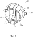
- FIG. 4 is a perspective view of a tunnel portion according to an example embodiment.
- FIG. 5 is a perspective view of an airway portion and a tube portion according to an example embodiment.
- the CPR training apparatus for infants 1 may include a body portion 11, a head portion 12, a tunnel portion 13, an airway portion 14, and a tube portion 15.
- the body portion 11 may constitute a body portion of an infant mannequin.
- the body portion 11 may be formed in a shape similar to that of an infant's body.
- the body portion 11 may have an external shape based on a standard body shape of the infant so that a user performing training has a feeling of a situation similar to an actual situation.
- the body portion 11 may include a torso, arms, and legs.
- An appearance of the body portion 11 may be formed to have shapes such as a xiphoid process, ribs, nipples, and the like. According to such a structure, when the user performs chest compression on the body portion 11, an exact chest compression position may be verified.
- the body portion 11 may include a space therein.
- a component for CPR or artificial respiration training may be disposed inside the body portion 11.
- an artificial lung may be disposed inside the body portion 11.
- the body portion 11 may be formed to be openable for installation, replacement, or inspection of the component installed therein.
- the head portion 12 may constitute a head portion of the infant mannequin.
- the head portion 12 may be rotatably connected to the body portion 11. A detailed description of connection between the head portion 12 and the body portion 11 will be described later.
- the head portion 12 may include a head frame 121 and a chin frame 122.
- the head frame 121 may be formed in a shape similar to that of the infant's head.
- the head frame 121 may have an external shape based on the standard body shape of the infant so that a user performing training has a feeling of a situation similar to an actual situation.
- the head frame 121 may have eyes, a nose, and a mouth.
- the head frame 121 may include a space therein.
- a component for CPR or artificial respiration training may be disposed inside the head frame 121.
- the head frame 121 may be formed to be openable for installation, replacement, or inspection of the component installed therein.
- the head frame 121 may include a left head and a right head, and the heads may be coupled to each other or separated from each other in a horizontal direction.
- the chin frame 122 may be formed in a shape similar to that of the infant's chin.
- the chin frame 122 may have an external shape based on the standard body shape of the infant so that the user performing training has a feeling of a situation similar to an actual situation.
- the chin frame 122 may be connected to a lower end of the head frame 121 so as to be translatable in a vertical direction with respect to the head frame 121.
- the vertical direction may refer to a direction perpendicular to the ground based on a state in which the CPR training apparatus for infants 1 is laid on the floor.
- the chin frame 122 may include guide grooves 122a formed in portions extending in a longitudinal direction from each of opposite lower ends thereof, and the head frame 121 may include chin coupling portions 121a formed to protrude inward from each of the opposite lower ends.
- the chin coupling portion 121a may be slidably coupled to the guide groove 122a to connect the chin frame 122 and the head frame 121 to each other.
- the chin frame 122 may be translatable with respect to the head frame 121 along a longitudinal direction of the guide groove 122a.
- the chin frame 122 may be pulled or recede from the head frame 121 in a similar manner to an actual human body, and thus the user may perform an operation of pulling the chin during CPR.
- the airway is opened only when the chin is pulled.
- the CPR training apparatus for infants 1 may provide an environment similar to an actual environment, thereby increasing a learning effect.
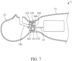
- FIGS. 6 to 8 are schematic cross-sectional views of a CPR training apparatus for infants according to an example embodiment, the views illustrating a relative positional relationship between a tunnel portion and an airway portion based on an angle at which a head portion is tilted with respect to a body portion and whether a tube portion is opened or closed.
- the tunnel portion 13 may be installed on a neck of the body portion 11.
- the tunnel portion 13 may have a through-space therein, and the through-space may provide a path that connects the inside of the head portion 12 and the inside of the body portion 11 to each other.
- the airway portion 14 and the tube portion 15 to be described later may be connected to an artificial lung positioned inside the body portion 11 through the tunnel portion 13.
- the tunnel portion 13 may mediate connection between the head portion 12 and the body portion 11.
- the tunnel portion 13 may include a tunnel frame 131, a lower catching protrusion 132, and an upper catching protrusion 133.
- the tunnel frame 131 may include a hollow cylindrical frame.
- the tunnel frame 131 may be formed to have a size and shape corresponding to those of the neck of the body portion 11, and thus may be fixedly installed on the neck of the body 11.
- the tunnel frame 131 may include a pair of vertical walls 131a that vertically connect upper and lower sides of an inner through-space to each other.
- the pair of vertical walls 131a may be positioned to be spaced apart from each other by a predetermined distance.
- the tunnel frame 131 may include a head coupling portion 131b protruding from the outside to each of opposite sides thereof.
- the head coupling portion 131b may be exposed to the outside in a state in which the tunnel frame 131 is coupled to the body portion 11.
- the head frame 121 may include a head coupling hole 121b that is formed through or recessed at each of opposite lower ends of the head frame 121 so that the head coupling portion 131b is inserted. As the head coupling portion 131b is inserted into the head coupling hole 121b, the head frame 121 may be connected to the tunnel frame 131.
- a lower catching protrusion 132 may extend from a lower side of tunnel frame 131 to an upper side of the tunnel frame 131.
- An upper catching protrusion 133 may extend from the upper side of the tunnel frame 131 to the lower side of the tunnel frame 131.
- the upper and lower sides may refer to upper and lower sides in a direction perpendicular to the ground, based on a state in which the CPR training apparatus for infants 1 is laid on the ground.
- the lower catching protrusion 132 may be relatively formed at a rear end of the tunnel frame 131 in comparison to the upper catching protrusion 133.
- the front and rear may respectively refer to a head side and a foot side in a height direction of a mannequin, based on a state in which the CPR training apparatus for infants 1 is laid on the ground.
- the lower catching protrusion 132 may be formed on a rear end portion of the tunnel frame 131
- the upper catching protrusion 133 may be formed on a front end portion or a middle portion of the tunnel frame 131.
- An extended length of the upper catching protrusion 133 may be longer than that of the lower catching protrusion 132.
- the upper catching protrusion 133 may be formed to have a length greater than or equal to a radius of the tunnel frame 131.
- the lower catching protrusion 132 may be formed to have a length less than the radius of the tunnel frame 131.
- a sum of the lengths of the upper catching protrusion 133 and the lower catching protrusion 132 may be less than a diameter of the tunnel frame 131. That is, a path through which the tube portion 15 passes may be formed between the upper catching protrusion 133 and the lower catching protrusion 132.
- the lower catching protrusion 132 and the upper catching protrusion 133 may be formed in a space between the pair of vertical walls 131a.
- the lower catching protrusion 132 may have a width corresponding to a distance between the pair of vertical walls 131a.
- the upper catching protrusion 133 may have a width less than the distance between the pair of vertical walls 131a. Accordingly, the pair of vertical walls 131a and the upper catching protrusion 133 may be spaced apart from each other, and a space may be formed therebetween in a width direction.
- the airway portion 14 may connect a mouth of the head portion 12 and the artificial lung to provide a path through which air is injected or discharged.
- the airway portion 14 may be fixedly connected to the head frame 121. Accordingly, when the head portion 12 rotates with respect to the body portion 11, the airway portion 14 may rotate together with the head portion 12. An end of the airway portion 14 may be inserted into an inner space of the tunnel portion 13. With the rotation of the head portion 12, the end of the airway portion 14 may rotate in the inner space of the tunnel portion 13 to open or close the tube portion 15.
- the airway portion 14 may include an airway tube 141, a neutral closure portion 142, a hyperextension closure portion 143, and a connection frame 144.
- the airway tube 141 may be installed to be in communication with the mouth of the head portion 12.
- the tube portion 15 to be described later may be connected to an end of the airway tube 141. That is, the airway tube 141 may provide a movement path of air that communicates from the mouth to the tube portion 15.
- the neutral closure portion 142 and the hyperextension closure portion 143 may be connected to the outside of the airway tube 141 by the connection frame 144.
- the neutral closure portion 142 and the hyperextension closure portion 143 may have a traverse length.
- the neutral closure portion 142 and the hyperextension closure portion 143 may have a width corresponding to or less than the distance between the pair of vertical walls 131a.
- the neutral closure portion 142, the hyperextension closure portion 143, and the connection frame 144 may be inserted into an inner space of the tunnel frame 131.
- the neutral closure portion 142 may be positioned above the lower catching protrusion 132, and the hyperextension closure portion 143 may be positioned below the upper catching protrusion 133.
- the above and below may refer to upper and lower sides in a direction perpendicular to the ground, based on the state in which the CPR training apparatus for infants 1 is laid on the ground.
- the neutral closure portion 142 may be positioned relatively above and behind the hyperextension closure portion 143.
- the above and below may refer to upper and lower sides in a direction perpendicular to the ground, based on the state in which the CPR training apparatus for infants 1 is laid on the ground.
- the front and behind may respectively refer to a head side and a foot side in a height direction of a mannequin, based on the state in which the CPR training apparatus for infants 1 is laid on the ground.
- connection frame 144 may connect the neutral closure portion 142 and the hyperextension closure portion 143 to the outside of the airway tube 141.
- the connection frame 144 may be provided as a pair in order to connect each of opposite sides of the neutral closure portion 142 and the hyperextension closure portion 143 having a traverse length to each other, respectively.
- connection frame 144 may include a first connection frame 144a, a second connection frame 144b, and a third connection frame 144c.
- the first connection frame 144a may connect one side of the airway tube 141 and the neutral closure portion 142 to each other.
- the first connection frame 144a may be inserted into a traverse space between the upper catching protrusion 133 and the vertical wall 131a.
- the second connection frame 144b may connect the neutral closure portion 142 and the hyperextension closure portion 143 to each other.
- the third connection frame 144c may connect the hyperextension closure portion 143 and the other side of the airway tube 141 to each other.
- a connection portion between the second connection frame 144b, the hyperextension closure portion 143, and the third connection frame 144c may be formed in a round shape so as to smoothly contact a bottom surface of the tunnel frame 131and rotate with respect to the bottom surface.
- the tube portion 15 may connect the airway tube 141 and the artificial lung to each other. That is, the tube portion 15 may provide an air movement path from the airway tube 141 to the artificial lung.
- the tube portion 15 may pass between the neutral closure portion 142 and the hyperextension closure portion 143. Specifically, the tube portion 15 may pass through a frame formed by the neutral closure portion 142, the hyperextension closure portion 143, and the pair of second connection frames 144b.
- the tube portion 15 may pass through the inner space of the tunnel portion 13. Specifically, the tube portion 15 may pass through the tunnel portion 13 between the lower catching protrusion 132 and the neutral closure portion 142.
- the tube portion 15 may pass through the tunnel portion 13 between the upper catching protrusion 133 and the hyperextension closure portion 143.
- the tube portion 15 may include an elastically deformable material. Accordingly, the tube portion 15 may be closed or opened according to the contact or spacing between the lower catching protrusion 132 and the neutral closure portion 142. In addition, the tube portion 15 may be closed or opened according to the contact or spacing between the upper catching protrusion 133 and the hyperextension closure portion 143.
- FIG. 6 illustrates a state in which the tube portion 15 is closed when the head portion 12 is in a neutral state with respect to the body portion 11.
- the neutral state may refer to a state in which the CPR training apparatus for infants 1 is naturally laid on the ground. That is, the neutral state may refer to a state in which the head portion 12 is not tilted with respect to the body portion 11.
- the neutral closure portion 142 may be in contact with the lower catching protrusion 132, and the hyperextension closure portion 143 may be spaced apart from the upper catching protrusion 133.
- the tube portion 15 may be closed according to the contact between the neutral closure portion 142 and the lower catching protrusion 132, and accordingly, the air movement path from the mouth to the artificial lung may be blocked.
- a user may not perform artificial respiration in the neutral state.
- the user may realize the need to tilt the head portion 12 at a predetermined angle or more with respect to the body portion 11.
- FIG. 7 illustrates a state in which the tube portion 15 is opened when the head portion 12 is in a state in which the head portion 12 is tilted at a predetermined angle or more and an angle less than a hyperextension angle with respect to the body portion 11.
- the state in which the head portion 12 is tilted at the predetermined angle or more and the angle less than the hyperextension angle may be a state in which the head portion 12 is tilted in an angle range suitable for performing artificial respiration on an infant.
- an angle at which a nose and ears are tilted to be perpendicular to the ground may be included in the above-described range.
- the neutral closure portion 142 When the head portion 12 rotates at the predetermined angle or more with respect to the body portion 11, the neutral closure portion 142 also may rotate around the head coupling portion 131b and the head coupling hole 121b, and accordingly may be spaced apart from the lower catching protrusion 132. Accordingly, in such a state, the neutral closure portion 142 may be spaced apart from the lower catching protrusion 132 to open the tube portion 15. In addition, in the state in which the head portion 12 is tilted at the predetermined angle or more and the angle less than the hyperextension angle with respect to the body portion 11, the hyperextension closure portion 143 may remain in a state in which it is spaced apart from the upper catching protrusion 133.
- the tube portion 15 may be opened, and accordingly the air movement path from the mouth to the artificial lung may be opened, thereby allowing the user to perform artificial respiration.
- the user may practice artificial respiration while realizing the need to tilt the head portion 12 at the predetermined angle or more with respect to the body portion 11 in order to perform artificial respiration.
- FIG. 8 illustrates a state in which the tube portion 15 is closed when the head portion 12 is in a state in which the head portion 12 is tilted at a hyperextension angle or more with respect to the body portion 11.
- the hyperextension angle may refer to an angle at which the head portion 12 is excessively tilted with respect to the body portion 11.
- the hyperextension angle may be set to ## degrees to ## degrees.
- the hyperextension closure portion 143 When the head portion 12 rotates at the hyperextension angle or more with respect to the body portion 11, the hyperextension closure portion 143 also may rotate around the head coupling portion 131b and the head coupling hole 121b, and accordingly may be in contact with the upper catching protrusion 133.
- the neutral closure portion 142 may be far away from the lower catching protrusion 132, and accordingly may remain in a state in which it is spaced apart from the lower catching protrusion 135.
- the tube portion 15 may be closed according to the contact between the hyperextension closure portion 143 and the upper catching protrusion 133, and accordingly, the air movement path from the mouth to the artificial lung may be blocked.
- the user may not perform artificial respiration in the hyperextension state. Accordingly, the user may perform training while realizing the need to tilt the head portion 12 only in a proper range with respect to the body portion 11.
Landscapes
- Health & Medical Sciences (AREA)
- Engineering & Computer Science (AREA)
- Physics & Mathematics (AREA)
- General Physics & Mathematics (AREA)
- Cardiology (AREA)
- Heart & Thoracic Surgery (AREA)
- General Health & Medical Sciences (AREA)
- Business, Economics & Management (AREA)
- Medicinal Chemistry (AREA)
- Algebra (AREA)
- Computational Mathematics (AREA)
- Medical Informatics (AREA)
- Mathematical Analysis (AREA)
- Mathematical Optimization (AREA)
- Mathematical Physics (AREA)
- Pure & Applied Mathematics (AREA)
- Chemical & Material Sciences (AREA)
- Educational Administration (AREA)
- Educational Technology (AREA)
- Theoretical Computer Science (AREA)
- Emergency Medicine (AREA)
- Pulmonology (AREA)
- Epidemiology (AREA)
- Pain & Pain Management (AREA)
- Physical Education & Sports Medicine (AREA)
- Rehabilitation Therapy (AREA)
- Life Sciences & Earth Sciences (AREA)
- Animal Behavior & Ethology (AREA)
- Public Health (AREA)
- Veterinary Medicine (AREA)
- Rehabilitation Tools (AREA)
- Instructional Devices (AREA)
Description
- Example embodiments relate to a cardiopulmonary resuscitation (CPR) training apparatus for infants.
- Cardiopulmonary resuscitation (CPR) is an emergency procedure to resuscitate a patient who has slowed or stopped cardiopulmonary function by restoring the cardiopulmonary function. CPR circulates blood when the heart is paralyzed, so that it is critical to helping to delay damage to the brain and recover the paralyzed heart. The method of CPR depends on whether the target is an adult, child, or infant. Therefore, it is important to acquaint yourself with CPR for each target in advance. In general, the CPR education is conducted through two-dimensional education such as display education or booklets, and thus there is a limit in that it cannot be effectively delivered to trainees. In order to increase a learning effect, there is a need for a training apparatus that enables CPR training in a situation similar to an actual situation.
- In case of infants, extra attention is required because CPR for infants is partially different from that for adults. For example, in case of infants, it is required to tilt the head slightly to open the airway, and tilting the head excessively may block the airway. Therefore, an additional CPR training apparatus for infants is required.
- The above-described background technology is possessed or acquired by the inventor(s) in a process of deriving the example embodiments, and is not necessarily a known technology disclosed to the general public prior to filing of the present application.
-
KR 101856203 (B1 - The invention relates to a cardiopulmonary resuscitation (CPR) training apparatus for infants as defined in the sole
independent claim 1. - Another aspect provides a CPR training apparatus for infants in which an airway is opened only when a head is slightly tilted and the airway is closed in a neutral position or when the head is excessively tilted.
- Still another aspect provides a CPR training apparatus for infants in which a chin may be raised.
- According to an aspect, there is provided a CPR training apparatus for infants including a body portion, a head portion including a head frame rotatably connected to the body portion, a tunnel portion including a tunnel frame installed on a neck of the body portion, and a lower catching protrusion extending from a lower side of the tunnel frame to an upper side of the tunnel frame, an airway portion including an airway tube installed to be in communication with a mouth of the head portion, and a neutral closure portion connected to an outside of the airway tube so as to be positioned above the lower catching protrusion, and a tube portion configured to connect the airway tube and an artificial lung to each other by passing through the tunnel portion between the lower catching protrusion and the neutral closure portion. The neutral closure portion may be in contact with the lower catching protrusion to close the tube portion when the head portion is in a neutral state with respect to the body portion, and the neutral closure portion may be spaced apart from the lower catching protrusion to open the tube portion when the head portion is tilted at a predetermined angle or more with respect to the body portion.
- The tunnel portion may further include an upper catching protrusion extending from the upper side of the tunnel frame to the lower side of the tunnel frame. The airway portion may further include a hyperextension closure portion connected to the outside of the airway tube so as to be positioned below the upper catching protrusion. The tube portion may pass through the tunnel portion between the upper catching protrusion and the hyperextension closure portion. The hyperextension closure portion may be spaced apart from the upper catching protrusion to open the tube portion when the head portion is tilted at an angle less than a hyperextension angle with respect to the body portion, and the hyperextension closure portion may be in contact with the upper catching protrusion to close the tube portion when the head portion is tilted at the hyperextension angle or more with respect to the body portion.
- The tube portion may be closed when the head portion is in the neutral state with respect to the body portion. The tube portion may be opened when the head portion is tilted at the predetermined angle or more and the angle less than the hyperextension angle with respect to the body portion. The tube portion may be closed when the head portion is tilted at the hyperextension angle or more with respect to the body portion.
- The airway portion may further include a connection frame configured to connect the neutral closure portion and the hyperextension closure portion to the outside of the airway tube.
- The neutral closure portion may be positioned relatively above and behind the hyperextension closure portion.
- The lower catching protrusion may be positioned relatively behind the tunnel portion in comparison to the upper catching protrusion.
- An extended length of the upper catching protrusion may be longer than an extended length of the lower catching protrusion.
- A sum of lengths of the upper catching protrusion and the lower catching protrusion may be less than a diameter of the tunnel frame.
- The tunnel portion may further include a head coupling portion protruding from an outside of the tunnel frame to each of opposite sides of the tunnel frame. The head portion may further include a head coupling hole formed through each of opposite sides of a lower end of the head frame so that the head coupling portion is inserted.
- The head portion may be rotatable with respect to the body portion and the tunnel portion using the head coupling portion and the head coupling hole as a central axis.
- The head portion may further include a chin frame connected to the lower end of the head frame so as to be translatable in a vertical direction with respect to the head frame.
- The head portion may further include a guide groove formed in a longitudinal direction at each of opposite lower ends of the chin frame, and a chin coupling portion protruding from each of opposite lower ends of the head frame, the chin coupling portion coupled to the guide groove.
- According to another aspect, there is provided a CPR training apparatus for infants including a body portion, a head portion including a head frame rotatably connected to the body portion, a tunnel portion including a tunnel frame installed on a neck of the body portion, and an upper catching protrusion extending from an upper side of the tunnel frame to a lower side of the tunnel frame, an airway portion including an airway tube installed to be in communication with a mouth of the head portion, and a hyperextension closure portion connected to an outside of the airway tube so as to be positioned below the upper catching protrusion, and a tube portion configured to connect the airway tube and an artificial lung by passing through the tunnel portion between the upper catching protrusion and the hyperextension closure portion. The hyperextension closure portion may be spaced apart from the upper catching protrusion to open the tube portion when the head portion is tilted at an angle less than a hyperextension angle with respect to the body portion, and the hyperextension closure portion may be in contact with the upper catching protrusion to close the tube portion when the head portion is tilted at the hyperextension angle or more with respect to the body portion.
- The CPR training apparatus for infants according to aspects may provide an environment similar to an actual CPR situation for infants.
- The CPR training apparatus for infants according to aspects may open an airway thereof only when a head thereof is slightly tilted, and may close the airway in a neutral position or when the head is excessively tilted, thereby training a correct posture.
- The CPR training apparatus for infants according to aspects may include a structure capable of raising a chin thereof, thereby creating an environment similar to an actual environment.
- Additional aspects of example embodiments will be set forth in part in the description which follows and, in part, will be apparent from the description, or may be learned by practice of the disclosure.
- These and/or other aspects, features, and advantages of the invention will become apparent and more readily appreciated from the following description of example embodiments, taken in conjunction with the accompanying drawings of which:
-
FIG. 1 is a schematic plan view of a cardiopulmonary resuscitation (CPR) training apparatus for infants according to an example embodiment; -
FIG. 2 is an assembled perspective view of a head portion according to an example embodiment; -
FIG. 3 is an exploded perspective view of a head portion, an airway portion, and a tube portion according to an example embodiment; -
FIG. 4 is a perspective view of a tunnel portion according to an example embodiment; -
FIG. 5 is a perspective view of an airway portion and a tube portion according to an example embodiment; and -
FIGS. 6 to 8 are schematic cross-sectional views of a CPR training apparatus for infants according to an example embodiment, the views illustrating a relative positional relationship between a tunnel portion and an airway portion based on an angle at which a head portion is tilted with respect to a body portion and whether a tube portion is opened or closed. - Hereinafter, example embodiments will be described in detail with reference to the accompanying drawings. The scope of the right, however, should not be construed as limited to the example embodiments set forth herein. Various modifications may be made to the example embodiments. Here, examples are not construed as limited to the example embodiments and should be understood to include all changes, equivalents, and replacements within the idea and the technical scope of the example embodiments.
- The terminology used herein is for the purpose of describing particular example embodiments only and is not intended to be limiting. As used herein, the singular forms "a," "an," and "the," are intended to include the plural forms as well, unless the context clearly indicates otherwise. It will be further understood. that the terms "comprises," "comprising," "includes," and/or "including," when used herein, specify the presence of stated features, integers, operations, elements, and/or components, but do not preclude the presence or addition of one or more other features, integers, operations, elements, components, and/or groups thereof.
- Unless otherwise defined, all terms, including technical and scientific terms, used herein have the same meaning as commonly understood by those skilled in the art to which the example embodiments pertain. Terms, such as those defined in commonly used dictionaries, are to be interpreted as having a meaning that is consistent with their meaning in the context of the relevant art, and are not to be interpreted in an idealized or overly formal sense unless expressly so defined herein.
- Regarding the reference numerals assigned to the components in the drawings, it should be noted that the same components will be designated by the same reference numerals, wherever possible, even though they are shown in different drawings. Further, in the description of example embodiments, detailed description of well-known related structures or functions will be omitted when it is deemed that such description will cause ambiguous interpretation of the example embodiments.
- In addition, it will be understood that, although the terms first, second, A, B, (a), (b), and the like may be used herein to describe various components of the example embodiments, these terms are only used to distinguish one component from another component and essential, order, or sequence of corresponding components are not limited by these terms. It will be understood that when one component is referred to as being "connected to", "coupled to", or "linked to" another component, one component may be "connected to", "coupled to", or "linked to" another component via a further component although one component may be directly connected to or directly linked to another component.
- The same name may be used to describe a component included in an example embodiment and a component having a common function in another example embodiment. Unless otherwise mentioned, the description on the example embodiment may be applicable to the other example embodiment and thus, duplicated description will be omitted for conciseness.
- Cardiopulmonary resuscitation (CPR) performed on infants will be briefly described. CPR for infants may be performed when they have no consciousness or breathing, when they have no voluntary movement, and when they have abnormal breathing or convulsive seizures. First, it is required to lay the infant on his/her back and lightly tap the sole of his/her foot to check whether he/she is conscious and breathing normally. Then, it is required to ask surrounding people for help, such as calling 911. Next, it is required to perform chest compressions. After bringing index and middle fingers together, it is required to bring first joints of the fingers into contact with the infant's sternum. A position to be compressed is the area right below the center of the line connecting both nipples of the infant. It is required to place the fingers perpendicular to the area that is in contact with the sternum, and to press firmly and quickly. Next, it is required to perform artificial respiration. It is required to raise the infant's chin with one hand so that his/her ears are parallel to the floor, and to tilt his/her head back with the other hand. It is required to perform artificial respiration by simultaneously blowing in the infant's mouth and nose so that his/her chest elevation is visually observed. It is required to repeat chest compressions and artificial respiration indefinitely until paramedics arrive. In performing CPR on infants, an appropriate chest compression depth and speed are required.
-
FIG. 1 is a schematic plan view of a CPR training apparatus for infants according to an example embodiment. - A CPR training apparatus for
infants 1 according to an example embodiment may be used for CPR training for infants. In performing CPR on infants, it may be important to perform artificial respiration in a correct posture. In particular, CPR for infants is different from CPR for adults in that the infant's airway may be opened only when his/her head is tilted slightly, and the airway may be closed when the head is excessively tilted. Therefore, the CPR training apparatus forinfants 1 may be configured such that the airway is opened only when the head is tilted in a predetermined range. Accordingly, a user may practice artificial respiration in a situation similar to a situation in which artificial respiration is performed on an actual infant, thereby increasing a training effect. -
FIG. 2 is an assembled perspective view of a head portion according to an example embodiment.FIG. 3 is an exploded perspective view of a head portion, an airway portion, and a tube portion according to an example embodiment.FIG. 4 is a perspective view of a tunnel portion according to an example embodiment.FIG. 5 is a perspective view of an airway portion and a tube portion according to an example embodiment. - Referring to
FIGS. 1 to 5 , the CPR training apparatus forinfants 1 according to an example embodiment may include abody portion 11, ahead portion 12, atunnel portion 13, anairway portion 14, and atube portion 15. - Referring to
FIG. 1 , thebody portion 11 may constitute a body portion of an infant mannequin. Thebody portion 11 may be formed in a shape similar to that of an infant's body. Thebody portion 11 may have an external shape based on a standard body shape of the infant so that a user performing training has a feeling of a situation similar to an actual situation. Thebody portion 11 may include a torso, arms, and legs. An appearance of thebody portion 11 may be formed to have shapes such as a xiphoid process, ribs, nipples, and the like. According to such a structure, when the user performs chest compression on thebody portion 11, an exact chest compression position may be verified. Thebody portion 11 may include a space therein. A component for CPR or artificial respiration training may be disposed inside thebody portion 11. For example, an artificial lung may be disposed inside thebody portion 11. Thebody portion 11 may be formed to be openable for installation, replacement, or inspection of the component installed therein. - Referring to
FIGS. 1 to 3 , thehead portion 12 may constitute a head portion of the infant mannequin. Thehead portion 12 may be rotatably connected to thebody portion 11. A detailed description of connection between thehead portion 12 and thebody portion 11 will be described later. - The
head portion 12 may include ahead frame 121 and achin frame 122. - The
head frame 121 may be formed in a shape similar to that of the infant's head. Thehead frame 121 may have an external shape based on the standard body shape of the infant so that a user performing training has a feeling of a situation similar to an actual situation. Thehead frame 121 may have eyes, a nose, and a mouth. Thehead frame 121 may include a space therein. A component for CPR or artificial respiration training may be disposed inside thehead frame 121. Thehead frame 121 may be formed to be openable for installation, replacement, or inspection of the component installed therein. For example, thehead frame 121 may include a left head and a right head, and the heads may be coupled to each other or separated from each other in a horizontal direction. - The
chin frame 122 may be formed in a shape similar to that of the infant's chin. Thechin frame 122 may have an external shape based on the standard body shape of the infant so that the user performing training has a feeling of a situation similar to an actual situation. Thechin frame 122 may be connected to a lower end of thehead frame 121 so as to be translatable in a vertical direction with respect to thehead frame 121. Here, the vertical direction may refer to a direction perpendicular to the ground based on a state in which the CPR training apparatus forinfants 1 is laid on the floor. For example, thechin frame 122 may includeguide grooves 122a formed in portions extending in a longitudinal direction from each of opposite lower ends thereof, and thehead frame 121 may includechin coupling portions 121a formed to protrude inward from each of the opposite lower ends. Thechin coupling portion 121a may be slidably coupled to theguide groove 122a to connect thechin frame 122 and thehead frame 121 to each other. According to such a structure, thechin frame 122 may be translatable with respect to thehead frame 121 along a longitudinal direction of theguide groove 122a. Accordingly, thechin frame 122 may be pulled or recede from thehead frame 121 in a similar manner to an actual human body, and thus the user may perform an operation of pulling the chin during CPR. In particular, since the infant's tongue is attached to the chin, the airway is opened only when the chin is pulled. In this regard, the CPR training apparatus forinfants 1 may provide an environment similar to an actual environment, thereby increasing a learning effect. -
FIGS. 6 to 8 are schematic cross-sectional views of a CPR training apparatus for infants according to an example embodiment, the views illustrating a relative positional relationship between a tunnel portion and an airway portion based on an angle at which a head portion is tilted with respect to a body portion and whether a tube portion is opened or closed. - Referring to
FIGS. 4 and6 to 8 , thetunnel portion 13 may be installed on a neck of thebody portion 11. Thetunnel portion 13 may have a through-space therein, and the through-space may provide a path that connects the inside of thehead portion 12 and the inside of thebody portion 11 to each other. Theairway portion 14 and thetube portion 15 to be described later may be connected to an artificial lung positioned inside thebody portion 11 through thetunnel portion 13. Thetunnel portion 13 may mediate connection between thehead portion 12 and thebody portion 11. - The
tunnel portion 13 may include atunnel frame 131, alower catching protrusion 132, and an upper catchingprotrusion 133. - The
tunnel frame 131 may include a hollow cylindrical frame. Thetunnel frame 131 may be formed to have a size and shape corresponding to those of the neck of thebody portion 11, and thus may be fixedly installed on the neck of thebody 11. - In order to increase rigidity, the
tunnel frame 131 may include a pair ofvertical walls 131a that vertically connect upper and lower sides of an inner through-space to each other. The pair ofvertical walls 131a may be positioned to be spaced apart from each other by a predetermined distance. - The
tunnel frame 131 may include ahead coupling portion 131b protruding from the outside to each of opposite sides thereof. Thehead coupling portion 131b may be exposed to the outside in a state in which thetunnel frame 131 is coupled to thebody portion 11. Thehead frame 121 may include ahead coupling hole 121b that is formed through or recessed at each of opposite lower ends of thehead frame 121 so that thehead coupling portion 131b is inserted. As thehead coupling portion 131b is inserted into thehead coupling hole 121b, thehead frame 121 may be connected to thetunnel frame 131. According to such a structure, thehead frame 121 may be rotatable with respect to thebody portion 11 and thetunnel portion 13 using thehead coupling portion 131b and the head coupling hole 122b as a central axis. That is, thehead portion 12 may be relatively tilted or pulled with respect to thebody portion 11 around thehead coupling portion 131b and the head coupling hole 122b. A coupling portion may be formed to protrude from thehead frame 121, and a coupling hole may be formed through or recessed in thetunnel portion 13. - A
lower catching protrusion 132 may extend from a lower side oftunnel frame 131 to an upper side of thetunnel frame 131. An upper catchingprotrusion 133 may extend from the upper side of thetunnel frame 131 to the lower side of thetunnel frame 131. The upper and lower sides may refer to upper and lower sides in a direction perpendicular to the ground, based on a state in which the CPR training apparatus forinfants 1 is laid on the ground. - The
lower catching protrusion 132 may be relatively formed at a rear end of thetunnel frame 131 in comparison to the upper catchingprotrusion 133. The front and rear may respectively refer to a head side and a foot side in a height direction of a mannequin, based on a state in which the CPR training apparatus forinfants 1 is laid on the ground. For example, thelower catching protrusion 132 may be formed on a rear end portion of thetunnel frame 131, and the upper catchingprotrusion 133 may be formed on a front end portion or a middle portion of thetunnel frame 131. - An extended length of the upper catching
protrusion 133 may be longer than that of thelower catching protrusion 132. For example, the upper catchingprotrusion 133 may be formed to have a length greater than or equal to a radius of thetunnel frame 131. Thelower catching protrusion 132 may be formed to have a length less than the radius of thetunnel frame 131. A sum of the lengths of the upper catchingprotrusion 133 and thelower catching protrusion 132 may be less than a diameter of thetunnel frame 131. That is, a path through which thetube portion 15 passes may be formed between the upper catchingprotrusion 133 and thelower catching protrusion 132. - The
lower catching protrusion 132 and the upper catchingprotrusion 133 may be formed in a space between the pair ofvertical walls 131a. Thelower catching protrusion 132 may have a width corresponding to a distance between the pair ofvertical walls 131a. The upper catchingprotrusion 133 may have a width less than the distance between the pair ofvertical walls 131a. Accordingly, the pair ofvertical walls 131a and the upper catchingprotrusion 133 may be spaced apart from each other, and a space may be formed therebetween in a width direction. - Referring to
FIGS. 3 and5 to 8 , theairway portion 14 may connect a mouth of thehead portion 12 and the artificial lung to provide a path through which air is injected or discharged. Theairway portion 14 may be fixedly connected to thehead frame 121. Accordingly, when thehead portion 12 rotates with respect to thebody portion 11, theairway portion 14 may rotate together with thehead portion 12. An end of theairway portion 14 may be inserted into an inner space of thetunnel portion 13. With the rotation of thehead portion 12, the end of theairway portion 14 may rotate in the inner space of thetunnel portion 13 to open or close thetube portion 15. - The
airway portion 14 may include anairway tube 141, aneutral closure portion 142, ahyperextension closure portion 143, and aconnection frame 144. - The
airway tube 141 may be installed to be in communication with the mouth of thehead portion 12. Thetube portion 15 to be described later may be connected to an end of theairway tube 141. That is, theairway tube 141 may provide a movement path of air that communicates from the mouth to thetube portion 15. - The
neutral closure portion 142 and thehyperextension closure portion 143 may be connected to the outside of theairway tube 141 by theconnection frame 144. Theneutral closure portion 142 and thehyperextension closure portion 143 may have a traverse length. Theneutral closure portion 142 and thehyperextension closure portion 143 may have a width corresponding to or less than the distance between the pair ofvertical walls 131a. Theneutral closure portion 142, thehyperextension closure portion 143, and theconnection frame 144 may be inserted into an inner space of thetunnel frame 131. - In a state in which the
airway portion 14 is inserted into the inner space of thetunnel portion 13, theneutral closure portion 142 may be positioned above thelower catching protrusion 132, and thehyperextension closure portion 143 may be positioned below the upper catchingprotrusion 133. The above and below may refer to upper and lower sides in a direction perpendicular to the ground, based on the state in which the CPR training apparatus forinfants 1 is laid on the ground. - In a state in which the
airway portion 14 is inserted into the inner space of thetunnel portion 13, theneutral closure portion 142 may be positioned relatively above and behind thehyperextension closure portion 143. The above and below may refer to upper and lower sides in a direction perpendicular to the ground, based on the state in which the CPR training apparatus forinfants 1 is laid on the ground. The front and behind may respectively refer to a head side and a foot side in a height direction of a mannequin, based on the state in which the CPR training apparatus forinfants 1 is laid on the ground. - The
connection frame 144 may connect theneutral closure portion 142 and thehyperextension closure portion 143 to the outside of theairway tube 141. Theconnection frame 144 may be provided as a pair in order to connect each of opposite sides of theneutral closure portion 142 and thehyperextension closure portion 143 having a traverse length to each other, respectively. - The
connection frame 144 may include a first connection frame 144a, asecond connection frame 144b, and athird connection frame 144c. - The first connection frame 144a may connect one side of the
airway tube 141 and theneutral closure portion 142 to each other. The first connection frame 144a may be inserted into a traverse space between the upper catchingprotrusion 133 and thevertical wall 131a. - The
second connection frame 144b may connect theneutral closure portion 142 and thehyperextension closure portion 143 to each other. Thethird connection frame 144c may connect thehyperextension closure portion 143 and the other side of theairway tube 141 to each other. A connection portion between thesecond connection frame 144b, thehyperextension closure portion 143, and thethird connection frame 144c may be formed in a round shape so as to smoothly contact a bottom surface of the tunnel frame 131and rotate with respect to the bottom surface. - Referring to
FIGS. 5 to 8 , thetube portion 15 may connect theairway tube 141 and the artificial lung to each other. That is, thetube portion 15 may provide an air movement path from theairway tube 141 to the artificial lung. Thetube portion 15 may pass between theneutral closure portion 142 and thehyperextension closure portion 143. Specifically, thetube portion 15 may pass through a frame formed by theneutral closure portion 142, thehyperextension closure portion 143, and the pair of second connection frames 144b. In addition, thetube portion 15 may pass through the inner space of thetunnel portion 13. Specifically, thetube portion 15 may pass through thetunnel portion 13 between thelower catching protrusion 132 and theneutral closure portion 142. In addition, thetube portion 15 may pass through thetunnel portion 13 between the upper catchingprotrusion 133 and thehyperextension closure portion 143. Thetube portion 15 may include an elastically deformable material. Accordingly, thetube portion 15 may be closed or opened according to the contact or spacing between thelower catching protrusion 132 and theneutral closure portion 142. In addition, thetube portion 15 may be closed or opened according to the contact or spacing between the upper catchingprotrusion 133 and thehyperextension closure portion 143. - Hereinafter, with reference to
FIGS. 6 to 8 , whether thetube portion 15 is opened or closed according to an angle at which thehead portion 12 is tilted with respect to thebody portion 11 will be described. -
FIG. 6 illustrates a state in which thetube portion 15 is closed when thehead portion 12 is in a neutral state with respect to thebody portion 11. The neutral state may refer to a state in which the CPR training apparatus forinfants 1 is naturally laid on the ground. That is, the neutral state may refer to a state in which thehead portion 12 is not tilted with respect to thebody portion 11. In the neutral state, theneutral closure portion 142 may be in contact with thelower catching protrusion 132, and thehyperextension closure portion 143 may be spaced apart from the upper catchingprotrusion 133. According to such a state, thetube portion 15 may be closed according to the contact between theneutral closure portion 142 and thelower catching protrusion 132, and accordingly, the air movement path from the mouth to the artificial lung may be blocked. As a result, a user may not perform artificial respiration in the neutral state. In order to perform artificial respiration, the user may realize the need to tilt thehead portion 12 at a predetermined angle or more with respect to thebody portion 11. -
FIG. 7 illustrates a state in which thetube portion 15 is opened when thehead portion 12 is in a state in which thehead portion 12 is tilted at a predetermined angle or more and an angle less than a hyperextension angle with respect to thebody portion 11. The state in which thehead portion 12 is tilted at the predetermined angle or more and the angle less than the hyperextension angle may be a state in which thehead portion 12 is tilted in an angle range suitable for performing artificial respiration on an infant. For example, an angle at which a nose and ears are tilted to be perpendicular to the ground may be included in the above-described range. When thehead portion 12 rotates at the predetermined angle or more with respect to thebody portion 11, theneutral closure portion 142 also may rotate around thehead coupling portion 131b and thehead coupling hole 121b, and accordingly may be spaced apart from thelower catching protrusion 132. Accordingly, in such a state, theneutral closure portion 142 may be spaced apart from thelower catching protrusion 132 to open thetube portion 15. In addition, in the state in which thehead portion 12 is tilted at the predetermined angle or more and the angle less than the hyperextension angle with respect to thebody portion 11, thehyperextension closure portion 143 may remain in a state in which it is spaced apart from the upper catchingprotrusion 133. Accordingly, in the state in which thehead portion 12 is tilted at the predetermined angle or more and the angle less than the hyperextension angle with respect to thebody portion 11, thetube portion 15 may be opened, and accordingly the air movement path from the mouth to the artificial lung may be opened, thereby allowing the user to perform artificial respiration. As a result, the user may practice artificial respiration while realizing the need to tilt thehead portion 12 at the predetermined angle or more with respect to thebody portion 11 in order to perform artificial respiration. -
FIG. 8 illustrates a state in which thetube portion 15 is closed when thehead portion 12 is in a state in which thehead portion 12 is tilted at a hyperextension angle or more with respect to thebody portion 11. The hyperextension angle may refer to an angle at which thehead portion 12 is excessively tilted with respect to thebody portion 11. For example, the hyperextension angle may be set to ## degrees to ## degrees. When an actual infant's head is excessively tilted, the infant's airway may be blocked and the infant's cervical spine may be injured, so it is required to be careful not to tilt the head excessively. When thehead portion 12 rotates at the hyperextension angle or more with respect to thebody portion 11, thehyperextension closure portion 143 also may rotate around thehead coupling portion 131b and thehead coupling hole 121b, and accordingly may be in contact with the upper catchingprotrusion 133. Theneutral closure portion 142 may be far away from thelower catching protrusion 132, and accordingly may remain in a state in which it is spaced apart from the lower catching protrusion 135. According to such a state, thetube portion 15 may be closed according to the contact between thehyperextension closure portion 143 and the upper catchingprotrusion 133, and accordingly, the air movement path from the mouth to the artificial lung may be blocked. As a result, the user may not perform artificial respiration in the hyperextension state. Accordingly, the user may perform training while realizing the need to tilt thehead portion 12 only in a proper range with respect to thebody portion 11. - A number of example embodiments have been described above. Nevertheless, it should be understood that various modifications may be made to these example embodiments. For example, suitable results may be achieved if the described techniques are performed in a different order and/or if components in a described system, architecture, device, or circuit are combined in a different manner and/or replaced or supplemented by other components or their equivalents.
- Accordingly, other implementations are within the scope of the following claims.
Claims (11)
- A cardiopulmonary resuscitation (CPR) training apparatus for infants (1), comprising:a body portion (11);a head portion (12) including a head frame (121) rotatably connected to the body portion (11);a tunnel portion (13) including a tunnel frame (131) installed on a neck of the body portion (11), and an upper catching protrusion (133) extending from an upper side of the tunnel frame (131) to a lower side of the tunnel frame (131);an airway portion (14) including an airway tube (141) installed to be in communication with a mouth of the head portion (12), and a hyperextension closure portion (143) connected to an outside of the airway tube (141) so as to be positioned below the upper catching protrusion (133); anda tube portion (15) configured to connect the airway tube (141) and an artificial lung to each other by passing through the tunnel portion (13) between the upper catching protrusion (133) and the hyperextension closure portion (143),wherein the hyperextension closure portion (143) is spaced apart from the upper catching protrusion (133) to open the tube portion (15) when the head portion (12) is tilted at an angle less than a hyperextension angle with respect to the body portion (11), and the hyperextension closure portion (143) is in contact with the upper catching protrusion (133) to close the tube portion (15) when the head portion (12) is tilted at the hyperextension angle or more with respect to the body portion (11); andwherein:the tunnel portion (13) further includes a lower catching protrusion (132) extending from a lower side of the tunnel frame (131) to an upper side of the tunnel frame (131),the airway portion (14) further includes a neutral closure portion (142) connected to an outside of the airway tube (141) so as to be positioned above the lower catching protrusion (132),the tube portion (15) passes through the tunnel portion (13) between the lower catching protrusion (132) and the neutral closure portion (142), andwherein the neutral closure portion (142) is in contact with the lower catching protrusion (132) to close the tube portion (15) when the head portion (12) is in a neutral state with respect to the body portion (11), and the neutral closure portion (142) is spaced apart from the lower catching protrusion (132) to open the tube portion (15) when the head portion (12) is tilted at a predetermined angle or more with respect to the body portion (11).
- The CPR training apparatus for infants (1) of claim 1, whereinthe tube portion (15) is closed when the head portion (12) is in the neutral state with respect to the body portion (11),the tube portion (15) is opened when the head portion (12) is tilted at the predetermined angle or more and the angle less than the hyperextension angle with respect to the body portion (11), andthe tube portion (15) is closed when the head portion (12) is tilted at the hyperextension angle or more with respect to the body portion (11).
- The CPR training apparatus for infants (1) of claim 2, wherein the airway portion (14) further includes a connection frame (144) configured to connect the neutral closure portion (142) and the hyperextension closure portion (143) to the outside of the airway tube (141).
- The CPR training apparatus for infants (1) of claim 2, wherein the neutral closure portion (142) is positioned relatively above and behind the hyperextension closure portion (143).
- The CPR training apparatus for infants (1) of claim 2, wherein the lower catching protrusion (132) is positioned relatively behind the tunnel portion (13) in comparison to the upper catching protrusion (133).
- The CPR training apparatus for infants (1) of claim 2, wherein an extended length of the upper catching protrusion (133) is longer than an extended length of the lower catching protrusion (132).
- The CPR training apparatus for infants (1) of claim 6, wherein a sum of lengths of the upper catching protrusion (133) and the lower catching protrusion (132) is less than a diameter of the tunnel frame (131).
- The CPR training apparatus for infants (1) of claim 1, whereinthe tunnel portion (13) further includes a head coupling portion (131b) protruding from an outside of the tunnel frame (131) to each of opposite sides of the tunnel frame (131), andthe head portion (12) further includes a head coupling hole (121b) formed through each of opposite sides of a lower end of the head frame (121) so that the head coupling portion (121b) is inserted.
- The CPR training apparatus for infants (1) of claim 8, wherein the head portion (12) is rotatable with respect to the body portion (11) and the tunnel portion (13) using the head coupling portion (131b) and the head coupling hole (121b) as a central axis.
- The CPR training apparatus for infants (1) of claim 1, wherein the head portion (12) further includes a chin frame (122) connected to the lower end of the head frame (121) so as to be translatable in a vertical direction with respect to the head frame (121).
- The CPR training apparatus for infants (1) of claim 10, wherein the head portion (12) further includes:a guide groove (122a) formed in a longitudinal direction at each of opposite lower ends of the chin frame (122); anda chin coupling portion (121a) protruding from each of opposite lower ends of the head frame (121), the chin coupling portion (121a) coupled to the guide groove (122a).
Applications Claiming Priority (1)
| Application Number | Priority Date | Filing Date | Title |
|---|---|---|---|
| KR1020200082699A KR102237640B1 (en) | 2020-07-06 | 2020-07-06 | Cardiopulmonary resuscitation training device for infants |
Publications (2)
| Publication Number | Publication Date |
|---|---|
| EP3937156A1 EP3937156A1 (en) | 2022-01-12 |
| EP3937156B1 true EP3937156B1 (en) | 2024-07-24 |
Family
ID=75444084
Family Applications (1)
| Application Number | Title | Priority Date | Filing Date |
|---|---|---|---|
| EP21183826.3A Active EP3937156B1 (en) | 2020-07-06 | 2021-07-05 | Cardiopulmonary resuscitation training apparatus for infants |
Country Status (3)
| Country | Link |
|---|---|
| US (1) | US12175884B2 (en) |
| EP (1) | EP3937156B1 (en) |
| KR (1) | KR102237640B1 (en) |
Families Citing this family (1)
| Publication number | Priority date | Publication date | Assignee | Title |
|---|---|---|---|---|
| CN117392904A (en) * | 2023-11-23 | 2024-01-12 | 挪度医疗器械(苏州)有限公司 | A multifunctional newborn head model |
Family Cites Families (12)
| Publication number | Priority date | Publication date | Assignee | Title |
|---|---|---|---|---|
| US4611998A (en) * | 1980-12-08 | 1986-09-16 | Board Of Regents, University Of Texas System | Simulator for teaching neonatal resuscitation |
| US5286206A (en) * | 1993-02-19 | 1994-02-15 | Actar Airforce, Inc. | CPR manikin and disposable lung bag |
| DE19700529A1 (en) * | 1997-01-09 | 1998-07-16 | Laerdal Asmund S As | Model for practicing cardiopulmonary resuscitation (CPR) in a human |
| US6780017B2 (en) * | 1998-09-21 | 2004-08-24 | Cardiac Science, Inc. | Cardiopulmonary resuscitation manikin with replaceable lung bag and installation tool |
| KR100887375B1 (en) | 2008-09-23 | 2009-03-06 | 이은숙 | CPR training mannequin |
| KR101298488B1 (en) * | 2011-09-06 | 2013-08-22 | 주식회사 비티 | Simulator for training of CPR |
| JP5475738B2 (en) * | 2011-10-13 | 2014-04-16 | 株式会社京都科学 | Tracheal intubation practice model |
| AT520146B1 (en) * | 2017-06-28 | 2019-03-15 | Simcharacters Gmbh | patient simulator |
| KR101856203B1 (en) * | 2017-07-04 | 2018-05-10 | 주식회사 이노소니언 | Cardiopulmonary resuscitation training device |
| KR101995675B1 (en) | 2018-10-19 | 2019-07-02 | 주식회사 이노소니언 | Chest compression module for infant and cpr training apparatus comprising the same |
| KR101981742B1 (en) | 2018-10-19 | 2019-05-27 | 주식회사 이노소니언 | Training apparatus for airway obstruction first aid |
| KR102014533B1 (en) * | 2019-06-27 | 2019-08-26 | 이정혁 | Mannequin of infant emergency treatment for paramedic training |
-
2020
- 2020-07-06 KR KR1020200082699A patent/KR102237640B1/en active Active
-
2021
- 2021-07-05 EP EP21183826.3A patent/EP3937156B1/en active Active
- 2021-07-06 US US17/305,376 patent/US12175884B2/en active Active
Also Published As
| Publication number | Publication date |
|---|---|
| US12175884B2 (en) | 2024-12-24 |
| US20220005377A1 (en) | 2022-01-06 |
| EP3937156A1 (en) | 2022-01-12 |
| KR102237640B1 (en) | 2021-04-09 |
Similar Documents
| Publication | Publication Date | Title |
|---|---|---|
| Dorfsman et al. | Two‐thumb vs two‐finger chest compression in an infant model of prolonged cardiopulmonary resuscitation | |
| US8016598B2 (en) | Interactive education system for teaching patient care | |
| US3199225A (en) | Resuscitation teaching apparatus | |
| AU660531B2 (en) | Training manikin for practising external cardiac massage | |
| KR100887375B1 (en) | CPR training mannequin | |
| US20120100516A1 (en) | Portable practice tool for heart massaging in cardiopulmonary resuscitation | |
| US12288477B2 (en) | System for simulating cervical spine motions | |
| WO2017156063A1 (en) | Physiological training system | |
| KR102191027B1 (en) | Cardiopulmonary resuscitation training system based on virtual reality | |
| KR101981742B1 (en) | Training apparatus for airway obstruction first aid | |
| KR102679149B1 (en) | Infant model for emergency treatment training | |
| KR102942876B1 (en) | Device for patient cardiopulmonary resuscitation | |
| US12175884B2 (en) | Cardiopulmonary resuscitation training apparatus for infants | |
| KR100903554B1 (en) | Model system for CPR training | |
| RU2124762C1 (en) | Training equipment for teaching of methods of urgent traumatologic and resuscitation help | |
| CN104188783A (en) | Neuro-muscular loop rebuilding and rehabilitation trainer | |
| KR101798534B1 (en) | Chest model device and cardiopulmonary resuscitation simulator comprising the same | |
| US3498293A (en) | Orientation apparatus for human subjects | |
| US10482791B2 (en) | Single use mannequin having chest compression feedback mechanism for use in simulated cardiopulmonary resuscitation (CPR) training | |
| KR101995675B1 (en) | Chest compression module for infant and cpr training apparatus comprising the same | |
| KR102014533B1 (en) | Mannequin of infant emergency treatment for paramedic training | |
| JP3245319U (en) | learning model | |
| KR102059536B1 (en) | Cpr trainging device for infant | |
| EP2437236B1 (en) | Device for simulating cardio-pulmonary resuscitation techniques | |
| ES2594876T3 (en) | Learning set and chest child torso simulator for learning the movement of respiratory kinesitherapy |
Legal Events
| Date | Code | Title | Description |
|---|---|---|---|
| PUAI | Public reference made under article 153(3) epc to a published international application that has entered the european phase |
Free format text: ORIGINAL CODE: 0009012 |
|
| STAA | Information on the status of an ep patent application or granted ep patent |
Free format text: STATUS: REQUEST FOR EXAMINATION WAS MADE |
|
| 17P | Request for examination filed |
Effective date: 20210705 |
|
| AK | Designated contracting states |
Kind code of ref document: A1 Designated state(s): AL AT BE BG CH CY CZ DE DK EE ES FI FR GB GR HR HU IE IS IT LI LT LU LV MC MK MT NL NO PL PT RO RS SE SI SK SM TR |
|
| B565 | Issuance of search results under rule 164(2) epc |
Effective date: 20211203 |
|
| GRAP | Despatch of communication of intention to grant a patent |
Free format text: ORIGINAL CODE: EPIDOSNIGR1 |
|
| STAA | Information on the status of an ep patent application or granted ep patent |
Free format text: STATUS: GRANT OF PATENT IS INTENDED |
|
| RIC1 | Information provided on ipc code assigned before grant |
Ipc: G09B 23/28 20060101AFI20240129BHEP |
|
| INTG | Intention to grant announced |
Effective date: 20240220 |
|
| GRAS | Grant fee paid |
Free format text: ORIGINAL CODE: EPIDOSNIGR3 |
|
| GRAA | (expected) grant |
Free format text: ORIGINAL CODE: 0009210 |
|
| STAA | Information on the status of an ep patent application or granted ep patent |
Free format text: STATUS: THE PATENT HAS BEEN GRANTED |
|
| AK | Designated contracting states |
Kind code of ref document: B1 Designated state(s): AL AT BE BG CH CY CZ DE DK EE ES FI FR GB GR HR HU IE IS IT LI LT LU LV MC MK MT NL NO PL PT RO RS SE SI SK SM TR |
|
| REG | Reference to a national code |
Ref country code: GB Ref legal event code: FG4D |
|
| REG | Reference to a national code |
Ref country code: CH Ref legal event code: EP |
|
| REG | Reference to a national code |
Ref country code: IE Ref legal event code: FG4D Ref country code: DE Ref legal event code: R096 Ref document number: 602021016029 Country of ref document: DE |
|
| REG | Reference to a national code |
Ref country code: LT Ref legal event code: MG9D |
|
| REG | Reference to a national code |
Ref country code: NL Ref legal event code: MP Effective date: 20240724 |
|
| PG25 | Lapsed in a contracting state [announced via postgrant information from national office to epo] |
Ref country code: PT Free format text: LAPSE BECAUSE OF FAILURE TO SUBMIT A TRANSLATION OF THE DESCRIPTION OR TO PAY THE FEE WITHIN THE PRESCRIBED TIME-LIMIT Effective date: 20241125 |
|
| REG | Reference to a national code |
Ref country code: AT Ref legal event code: MK05 Ref document number: 1707067 Country of ref document: AT Kind code of ref document: T Effective date: 20240724 |
|
| PG25 | Lapsed in a contracting state [announced via postgrant information from national office to epo] |
Ref country code: NL Free format text: LAPSE BECAUSE OF FAILURE TO SUBMIT A TRANSLATION OF THE DESCRIPTION OR TO PAY THE FEE WITHIN THE PRESCRIBED TIME-LIMIT Effective date: 20240724 |
|
| PG25 | Lapsed in a contracting state [announced via postgrant information from national office to epo] |
Ref country code: PT Free format text: LAPSE BECAUSE OF FAILURE TO SUBMIT A TRANSLATION OF THE DESCRIPTION OR TO PAY THE FEE WITHIN THE PRESCRIBED TIME-LIMIT Effective date: 20241125 Ref country code: NL Free format text: LAPSE BECAUSE OF FAILURE TO SUBMIT A TRANSLATION OF THE DESCRIPTION OR TO PAY THE FEE WITHIN THE PRESCRIBED TIME-LIMIT Effective date: 20240724 |
|
| PG25 | Lapsed in a contracting state [announced via postgrant information from national office to epo] |
Ref country code: NO Free format text: LAPSE BECAUSE OF FAILURE TO SUBMIT A TRANSLATION OF THE DESCRIPTION OR TO PAY THE FEE WITHIN THE PRESCRIBED TIME-LIMIT Effective date: 20241024 |
|
| PG25 | Lapsed in a contracting state [announced via postgrant information from national office to epo] |
Ref country code: FI Free format text: LAPSE BECAUSE OF FAILURE TO SUBMIT A TRANSLATION OF THE DESCRIPTION OR TO PAY THE FEE WITHIN THE PRESCRIBED TIME-LIMIT Effective date: 20240724 Ref country code: PL Free format text: LAPSE BECAUSE OF FAILURE TO SUBMIT A TRANSLATION OF THE DESCRIPTION OR TO PAY THE FEE WITHIN THE PRESCRIBED TIME-LIMIT Effective date: 20240724 Ref country code: GR Free format text: LAPSE BECAUSE OF FAILURE TO SUBMIT A TRANSLATION OF THE DESCRIPTION OR TO PAY THE FEE WITHIN THE PRESCRIBED TIME-LIMIT Effective date: 20241025 |
|
| PG25 | Lapsed in a contracting state [announced via postgrant information from national office to epo] |
Ref country code: BG Free format text: LAPSE BECAUSE OF FAILURE TO SUBMIT A TRANSLATION OF THE DESCRIPTION OR TO PAY THE FEE WITHIN THE PRESCRIBED TIME-LIMIT Effective date: 20240724 |
|
| PG25 | Lapsed in a contracting state [announced via postgrant information from national office to epo] |
Ref country code: LV Free format text: LAPSE BECAUSE OF FAILURE TO SUBMIT A TRANSLATION OF THE DESCRIPTION OR TO PAY THE FEE WITHIN THE PRESCRIBED TIME-LIMIT Effective date: 20240724 |
|
| PG25 | Lapsed in a contracting state [announced via postgrant information from national office to epo] |
Ref country code: IS Free format text: LAPSE BECAUSE OF FAILURE TO SUBMIT A TRANSLATION OF THE DESCRIPTION OR TO PAY THE FEE WITHIN THE PRESCRIBED TIME-LIMIT Effective date: 20241124 Ref country code: AT Free format text: LAPSE BECAUSE OF FAILURE TO SUBMIT A TRANSLATION OF THE DESCRIPTION OR TO PAY THE FEE WITHIN THE PRESCRIBED TIME-LIMIT Effective date: 20240724 |
|
| PG25 | Lapsed in a contracting state [announced via postgrant information from national office to epo] |
Ref country code: HR Free format text: LAPSE BECAUSE OF FAILURE TO SUBMIT A TRANSLATION OF THE DESCRIPTION OR TO PAY THE FEE WITHIN THE PRESCRIBED TIME-LIMIT Effective date: 20240724 |
|
| PG25 | Lapsed in a contracting state [announced via postgrant information from national office to epo] |
Ref country code: RS Free format text: LAPSE BECAUSE OF FAILURE TO SUBMIT A TRANSLATION OF THE DESCRIPTION OR TO PAY THE FEE WITHIN THE PRESCRIBED TIME-LIMIT Effective date: 20241024 Ref country code: ES Free format text: LAPSE BECAUSE OF FAILURE TO SUBMIT A TRANSLATION OF THE DESCRIPTION OR TO PAY THE FEE WITHIN THE PRESCRIBED TIME-LIMIT Effective date: 20240724 |
|
| PG25 | Lapsed in a contracting state [announced via postgrant information from national office to epo] |
Ref country code: RS Free format text: LAPSE BECAUSE OF FAILURE TO SUBMIT A TRANSLATION OF THE DESCRIPTION OR TO PAY THE FEE WITHIN THE PRESCRIBED TIME-LIMIT Effective date: 20241024 Ref country code: PL Free format text: LAPSE BECAUSE OF FAILURE TO SUBMIT A TRANSLATION OF THE DESCRIPTION OR TO PAY THE FEE WITHIN THE PRESCRIBED TIME-LIMIT Effective date: 20240724 Ref country code: NO Free format text: LAPSE BECAUSE OF FAILURE TO SUBMIT A TRANSLATION OF THE DESCRIPTION OR TO PAY THE FEE WITHIN THE PRESCRIBED TIME-LIMIT Effective date: 20241024 Ref country code: LV Free format text: LAPSE BECAUSE OF FAILURE TO SUBMIT A TRANSLATION OF THE DESCRIPTION OR TO PAY THE FEE WITHIN THE PRESCRIBED TIME-LIMIT Effective date: 20240724 Ref country code: IS Free format text: LAPSE BECAUSE OF FAILURE TO SUBMIT A TRANSLATION OF THE DESCRIPTION OR TO PAY THE FEE WITHIN THE PRESCRIBED TIME-LIMIT Effective date: 20241124 Ref country code: HR Free format text: LAPSE BECAUSE OF FAILURE TO SUBMIT A TRANSLATION OF THE DESCRIPTION OR TO PAY THE FEE WITHIN THE PRESCRIBED TIME-LIMIT Effective date: 20240724 Ref country code: GR Free format text: LAPSE BECAUSE OF FAILURE TO SUBMIT A TRANSLATION OF THE DESCRIPTION OR TO PAY THE FEE WITHIN THE PRESCRIBED TIME-LIMIT Effective date: 20241025 Ref country code: FI Free format text: LAPSE BECAUSE OF FAILURE TO SUBMIT A TRANSLATION OF THE DESCRIPTION OR TO PAY THE FEE WITHIN THE PRESCRIBED TIME-LIMIT Effective date: 20240724 Ref country code: ES Free format text: LAPSE BECAUSE OF FAILURE TO SUBMIT A TRANSLATION OF THE DESCRIPTION OR TO PAY THE FEE WITHIN THE PRESCRIBED TIME-LIMIT Effective date: 20240724 Ref country code: BG Free format text: LAPSE BECAUSE OF FAILURE TO SUBMIT A TRANSLATION OF THE DESCRIPTION OR TO PAY THE FEE WITHIN THE PRESCRIBED TIME-LIMIT Effective date: 20240724 Ref country code: AT Free format text: LAPSE BECAUSE OF FAILURE TO SUBMIT A TRANSLATION OF THE DESCRIPTION OR TO PAY THE FEE WITHIN THE PRESCRIBED TIME-LIMIT Effective date: 20240724 |
|
| PG25 | Lapsed in a contracting state [announced via postgrant information from national office to epo] |
Ref country code: SM Free format text: LAPSE BECAUSE OF FAILURE TO SUBMIT A TRANSLATION OF THE DESCRIPTION OR TO PAY THE FEE WITHIN THE PRESCRIBED TIME-LIMIT Effective date: 20240724 Ref country code: DK Free format text: LAPSE BECAUSE OF FAILURE TO SUBMIT A TRANSLATION OF THE DESCRIPTION OR TO PAY THE FEE WITHIN THE PRESCRIBED TIME-LIMIT Effective date: 20240724 Ref country code: RO Free format text: LAPSE BECAUSE OF FAILURE TO SUBMIT A TRANSLATION OF THE DESCRIPTION OR TO PAY THE FEE WITHIN THE PRESCRIBED TIME-LIMIT Effective date: 20240724 |
|
| PG25 | Lapsed in a contracting state [announced via postgrant information from national office to epo] |
Ref country code: EE Free format text: LAPSE BECAUSE OF FAILURE TO SUBMIT A TRANSLATION OF THE DESCRIPTION OR TO PAY THE FEE WITHIN THE PRESCRIBED TIME-LIMIT Effective date: 20240724 |
|
| PG25 | Lapsed in a contracting state [announced via postgrant information from national office to epo] |
Ref country code: CZ Free format text: LAPSE BECAUSE OF FAILURE TO SUBMIT A TRANSLATION OF THE DESCRIPTION OR TO PAY THE FEE WITHIN THE PRESCRIBED TIME-LIMIT Effective date: 20240724 |
|
| REG | Reference to a national code |
Ref country code: DE Ref legal event code: R097 Ref document number: 602021016029 Country of ref document: DE |
|
| PG25 | Lapsed in a contracting state [announced via postgrant information from national office to epo] |
Ref country code: IT Free format text: LAPSE BECAUSE OF FAILURE TO SUBMIT A TRANSLATION OF THE DESCRIPTION OR TO PAY THE FEE WITHIN THE PRESCRIBED TIME-LIMIT Effective date: 20240724 Ref country code: SK Free format text: LAPSE BECAUSE OF FAILURE TO SUBMIT A TRANSLATION OF THE DESCRIPTION OR TO PAY THE FEE WITHIN THE PRESCRIBED TIME-LIMIT Effective date: 20240724 |
|
| PLBE | No opposition filed within time limit |
Free format text: ORIGINAL CODE: 0009261 |
|
| STAA | Information on the status of an ep patent application or granted ep patent |
Free format text: STATUS: NO OPPOSITION FILED WITHIN TIME LIMIT |
|
| 26N | No opposition filed |
Effective date: 20250425 |
|
| PGFP | Annual fee paid to national office [announced via postgrant information from national office to epo] |
Ref country code: GB Payment date: 20250522 Year of fee payment: 5 |
|
| PGFP | Annual fee paid to national office [announced via postgrant information from national office to epo] |
Ref country code: FR Payment date: 20250523 Year of fee payment: 5 |
|
| PG25 | Lapsed in a contracting state [announced via postgrant information from national office to epo] |
Ref country code: SE Free format text: LAPSE BECAUSE OF FAILURE TO SUBMIT A TRANSLATION OF THE DESCRIPTION OR TO PAY THE FEE WITHIN THE PRESCRIBED TIME-LIMIT Effective date: 20240724 |
|
| PGFP | Annual fee paid to national office [announced via postgrant information from national office to epo] |
Ref country code: DE Payment date: 20250528 Year of fee payment: 5 |
|
| REG | Reference to a national code |
Ref country code: CH Ref legal event code: H13 Free format text: ST27 STATUS EVENT CODE: U-0-0-H10-H13 (AS PROVIDED BY THE NATIONAL OFFICE) Effective date: 20260224 |
|
| PG25 | Lapsed in a contracting state [announced via postgrant information from national office to epo] |
Ref country code: LU Free format text: LAPSE BECAUSE OF NON-PAYMENT OF DUE FEES Effective date: 20250705 |
|
| REG | Reference to a national code |
Ref country code: BE Ref legal event code: MM Effective date: 20250731 |
|
| PG25 | Lapsed in a contracting state [announced via postgrant information from national office to epo] |
Ref country code: BE Free format text: LAPSE BECAUSE OF NON-PAYMENT OF DUE FEES Effective date: 20250731 |
|
| PG25 | Lapsed in a contracting state [announced via postgrant information from national office to epo] |
Ref country code: CH Free format text: LAPSE BECAUSE OF NON-PAYMENT OF DUE FEES Effective date: 20250731 |
|
| PG25 | Lapsed in a contracting state [announced via postgrant information from national office to epo] |
Ref country code: LT Free format text: LAPSE BECAUSE OF FAILURE TO SUBMIT A TRANSLATION OF THE DESCRIPTION OR TO PAY THE FEE WITHIN THE PRESCRIBED TIME-LIMIT Effective date: 20240724 |
|
| PG25 | Lapsed in a contracting state [announced via postgrant information from national office to epo] |
Ref country code: IE Free format text: LAPSE BECAUSE OF NON-PAYMENT OF DUE FEES Effective date: 20250705 |
|
| PG25 | Lapsed in a contracting state [announced via postgrant information from national office to epo] |
Ref country code: MC Free format text: LAPSE BECAUSE OF FAILURE TO SUBMIT A TRANSLATION OF THE DESCRIPTION OR TO PAY THE FEE WITHIN THE PRESCRIBED TIME-LIMIT Effective date: 20240724 |
|
| PG25 | Lapsed in a contracting state [announced via postgrant information from national office to epo] |
Ref country code: CY Free format text: LAPSE BECAUSE OF FAILURE TO SUBMIT A TRANSLATION OF THE DESCRIPTION OR TO PAY THE FEE WITHIN THE PRESCRIBED TIME-LIMIT Effective date: 20240724 |