EP3936942A1 - Developer-supporting body, process cartridge, and electrophotographic image forming apparatus - Google Patents
Developer-supporting body, process cartridge, and electrophotographic image forming apparatus Download PDFInfo
- Publication number
- EP3936942A1 EP3936942A1 EP20770722.5A EP20770722A EP3936942A1 EP 3936942 A1 EP3936942 A1 EP 3936942A1 EP 20770722 A EP20770722 A EP 20770722A EP 3936942 A1 EP3936942 A1 EP 3936942A1
- Authority
- EP
- European Patent Office
- Prior art keywords
- developer carrying
- carrying member
- surface layer
- toner
- developer
- Prior art date
- Legal status (The legal status is an assumption and is not a legal conclusion. Google has not performed a legal analysis and makes no representation as to the accuracy of the status listed.)
- Withdrawn
Links
- 238000000034 method Methods 0.000 title claims description 33
- 230000008569 process Effects 0.000 title claims description 15
- 239000002344 surface layer Substances 0.000 claims abstract description 88
- 239000002245 particle Substances 0.000 claims abstract description 40
- 229920005989 resin Polymers 0.000 claims abstract description 36
- 239000011347 resin Substances 0.000 claims abstract description 36
- 229920005862 polyol Polymers 0.000 claims description 47
- 150000003077 polyols Chemical class 0.000 claims description 42
- 239000003973 paint Substances 0.000 claims description 34
- 239000006229 carbon black Substances 0.000 claims description 23
- 239000011230 binding agent Substances 0.000 claims description 22
- 239000000203 mixture Substances 0.000 claims description 21
- 229920002803 thermoplastic polyurethane Polymers 0.000 claims description 20
- 239000005056 polyisocyanate Substances 0.000 claims description 18
- 229920001228 polyisocyanate Polymers 0.000 claims description 18
- 229910052782 aluminium Inorganic materials 0.000 claims description 5
- XAGFODPZIPBFFR-UHFFFAOYSA-N aluminium Chemical compound [Al] XAGFODPZIPBFFR-UHFFFAOYSA-N 0.000 claims description 5
- PNEYBMLMFCGWSK-UHFFFAOYSA-N aluminium oxide Inorganic materials [O-2].[O-2].[O-2].[Al+3].[Al+3] PNEYBMLMFCGWSK-UHFFFAOYSA-N 0.000 claims description 2
- 239000010410 layer Substances 0.000 description 37
- 239000000463 material Substances 0.000 description 32
- 239000002994 raw material Substances 0.000 description 31
- 239000012948 isocyanate Substances 0.000 description 26
- 239000000126 substance Substances 0.000 description 26
- 150000002009 diols Chemical class 0.000 description 25
- 150000002513 isocyanates Chemical class 0.000 description 24
- -1 isocyanate compounds Chemical class 0.000 description 22
- 238000011156 evaluation Methods 0.000 description 19
- 229920000515 polycarbonate Polymers 0.000 description 17
- 239000004417 polycarbonate Substances 0.000 description 17
- 230000015572 biosynthetic process Effects 0.000 description 16
- 229920001971 elastomer Polymers 0.000 description 15
- WNLRTRBMVRJNCN-UHFFFAOYSA-N adipic acid Chemical compound OC(=O)CCCCC(O)=O WNLRTRBMVRJNCN-UHFFFAOYSA-N 0.000 description 14
- 239000005060 rubber Substances 0.000 description 14
- 239000011248 coating agent Substances 0.000 description 13
- 238000000576 coating method Methods 0.000 description 13
- 229920000459 Nitrile rubber Polymers 0.000 description 12
- 239000003795 chemical substances by application Substances 0.000 description 12
- 238000005259 measurement Methods 0.000 description 12
- ZWEHNKRNPOVVGH-UHFFFAOYSA-N 2-Butanone Chemical compound CCC(C)=O ZWEHNKRNPOVVGH-UHFFFAOYSA-N 0.000 description 11
- 238000003786 synthesis reaction Methods 0.000 description 11
- 230000000052 comparative effect Effects 0.000 description 10
- 239000007787 solid Substances 0.000 description 10
- 238000012546 transfer Methods 0.000 description 9
- XLOMVQKBTHCTTD-UHFFFAOYSA-N Zinc monoxide Chemical compound [Zn]=O XLOMVQKBTHCTTD-UHFFFAOYSA-N 0.000 description 8
- 238000006243 chemical reaction Methods 0.000 description 8
- 239000010419 fine particle Substances 0.000 description 8
- 239000002904 solvent Substances 0.000 description 8
- 239000000758 substrate Substances 0.000 description 8
- VYPSYNLAJGMNEJ-UHFFFAOYSA-N Silicium dioxide Chemical compound O=[Si]=O VYPSYNLAJGMNEJ-UHFFFAOYSA-N 0.000 description 7
- 229920006311 Urethane elastomer Polymers 0.000 description 7
- 235000011037 adipic acid Nutrition 0.000 description 7
- 239000001361 adipic acid Substances 0.000 description 7
- 238000011109 contamination Methods 0.000 description 7
- UPMLOUAZCHDJJD-UHFFFAOYSA-N 4,4'-Diphenylmethane Diisocyanate Chemical compound C1=CC(N=C=O)=CC=C1CC1=CC=C(N=C=O)C=C1 UPMLOUAZCHDJJD-UHFFFAOYSA-N 0.000 description 6
- VTYYLEPIZMXCLO-UHFFFAOYSA-L Calcium carbonate Chemical compound [Ca+2].[O-]C([O-])=O VTYYLEPIZMXCLO-UHFFFAOYSA-L 0.000 description 6
- OKTJSMMVPCPJKN-UHFFFAOYSA-N Carbon Chemical compound [C] OKTJSMMVPCPJKN-UHFFFAOYSA-N 0.000 description 6
- OFOBLEOULBTSOW-UHFFFAOYSA-N Malonic acid Chemical compound OC(=O)CC(O)=O OFOBLEOULBTSOW-UHFFFAOYSA-N 0.000 description 6
- 125000002947 alkylene group Chemical group 0.000 description 6
- WERYXYBDKMZEQL-UHFFFAOYSA-N butane-1,4-diol Chemical compound OCCCCO WERYXYBDKMZEQL-UHFFFAOYSA-N 0.000 description 6
- 125000004432 carbon atom Chemical group C* 0.000 description 6
- 239000000945 filler Substances 0.000 description 6
- 229910002804 graphite Inorganic materials 0.000 description 6
- 239000010439 graphite Substances 0.000 description 6
- 238000004519 manufacturing process Methods 0.000 description 6
- 229910052751 metal Inorganic materials 0.000 description 6
- 239000002184 metal Substances 0.000 description 6
- 238000002156 mixing Methods 0.000 description 6
- CXMXRPHRNRROMY-UHFFFAOYSA-N sebacic acid Chemical compound OC(=O)CCCCCCCCC(O)=O CXMXRPHRNRROMY-UHFFFAOYSA-N 0.000 description 6
- 125000002887 hydroxy group Chemical group [H]O* 0.000 description 5
- 229920005906 polyester polyol Polymers 0.000 description 5
- 229920000166 polytrimethylene carbonate Polymers 0.000 description 5
- 238000002360 preparation method Methods 0.000 description 5
- 230000002194 synthesizing effect Effects 0.000 description 5
- DNIAPMSPPWPWGF-VKHMYHEASA-N (+)-propylene glycol Chemical compound C[C@H](O)CO DNIAPMSPPWPWGF-VKHMYHEASA-N 0.000 description 4
- YPFDHNVEDLHUCE-UHFFFAOYSA-N 1,3-propanediol Substances OCCCO YPFDHNVEDLHUCE-UHFFFAOYSA-N 0.000 description 4
- IJGRMHOSHXDMSA-UHFFFAOYSA-N Atomic nitrogen Chemical compound N#N IJGRMHOSHXDMSA-UHFFFAOYSA-N 0.000 description 4
- OIFBSDVPJOWBCH-UHFFFAOYSA-N Diethyl carbonate Chemical compound CCOC(=O)OCC OIFBSDVPJOWBCH-UHFFFAOYSA-N 0.000 description 4
- JOYRKODLDBILNP-UHFFFAOYSA-N Ethyl urethane Chemical compound CCOC(N)=O JOYRKODLDBILNP-UHFFFAOYSA-N 0.000 description 4
- 239000004721 Polyphenylene oxide Substances 0.000 description 4
- GWEVSGVZZGPLCZ-UHFFFAOYSA-N Titan oxide Chemical compound O=[Ti]=O GWEVSGVZZGPLCZ-UHFFFAOYSA-N 0.000 description 4
- 229920001577 copolymer Polymers 0.000 description 4
- 239000003431 cross linking reagent Substances 0.000 description 4
- 239000008367 deionised water Substances 0.000 description 4
- 229910021641 deionized water Inorganic materials 0.000 description 4
- IQPQWNKOIGAROB-UHFFFAOYSA-N isocyanate group Chemical group [N-]=C=O IQPQWNKOIGAROB-UHFFFAOYSA-N 0.000 description 4
- WLJVNTCWHIRURA-UHFFFAOYSA-N pimelic acid Chemical compound OC(=O)CCCCCC(O)=O WLJVNTCWHIRURA-UHFFFAOYSA-N 0.000 description 4
- 229920006122 polyamide resin Polymers 0.000 description 4
- 229920000728 polyester Polymers 0.000 description 4
- 229920000570 polyether Polymers 0.000 description 4
- 230000001105 regulatory effect Effects 0.000 description 4
- TYFQFVWCELRYAO-UHFFFAOYSA-N suberic acid Chemical compound OC(=O)CCCCCCC(O)=O TYFQFVWCELRYAO-UHFFFAOYSA-N 0.000 description 4
- 238000012360 testing method Methods 0.000 description 4
- OGIDPMRJRNCKJF-UHFFFAOYSA-N titanium oxide Inorganic materials [Ti]=O OGIDPMRJRNCKJF-UHFFFAOYSA-N 0.000 description 4
- XLYOFNOQVPJJNP-UHFFFAOYSA-N water Chemical compound O XLYOFNOQVPJJNP-UHFFFAOYSA-N 0.000 description 4
- 239000011787 zinc oxide Substances 0.000 description 4
- LFQSCWFLJHTTHZ-UHFFFAOYSA-N Ethanol Chemical compound CCO LFQSCWFLJHTTHZ-UHFFFAOYSA-N 0.000 description 3
- 238000005299 abrasion Methods 0.000 description 3
- 239000002253 acid Substances 0.000 description 3
- 229910000019 calcium carbonate Inorganic materials 0.000 description 3
- 238000004364 calculation method Methods 0.000 description 3
- 238000004140 cleaning Methods 0.000 description 3
- 150000001875 compounds Chemical class 0.000 description 3
- 125000000753 cycloalkyl group Chemical group 0.000 description 3
- MTHSVFCYNBDYFN-UHFFFAOYSA-N diethylene glycol Chemical compound OCCOCCO MTHSVFCYNBDYFN-UHFFFAOYSA-N 0.000 description 3
- 238000011835 investigation Methods 0.000 description 3
- 239000007788 liquid Substances 0.000 description 3
- 229910044991 metal oxide Inorganic materials 0.000 description 3
- 150000004706 metal oxides Chemical class 0.000 description 3
- VLKZOEOYAKHREP-UHFFFAOYSA-N n-Hexane Chemical compound CCCCCC VLKZOEOYAKHREP-UHFFFAOYSA-N 0.000 description 3
- 239000012299 nitrogen atmosphere Substances 0.000 description 3
- 230000002093 peripheral effect Effects 0.000 description 3
- 229920005749 polyurethane resin Polymers 0.000 description 3
- 229920003002 synthetic resin Polymers 0.000 description 3
- 239000000057 synthetic resin Substances 0.000 description 3
- 238000004448 titration Methods 0.000 description 3
- RTBFRGCFXZNCOE-UHFFFAOYSA-N 1-methylsulfonylpiperidin-4-one Chemical compound CS(=O)(=O)N1CCC(=O)CC1 RTBFRGCFXZNCOE-UHFFFAOYSA-N 0.000 description 2
- DMWVYCCGCQPJEA-UHFFFAOYSA-N 2,5-bis(tert-butylperoxy)-2,5-dimethylhexane Chemical compound CC(C)(C)OOC(C)(C)CCC(C)(C)OOC(C)(C)C DMWVYCCGCQPJEA-UHFFFAOYSA-N 0.000 description 2
- XMNIXWIUMCBBBL-UHFFFAOYSA-N 2-(2-phenylpropan-2-ylperoxy)propan-2-ylbenzene Chemical compound C=1C=CC=CC=1C(C)(C)OOC(C)(C)C1=CC=CC=C1 XMNIXWIUMCBBBL-UHFFFAOYSA-N 0.000 description 2
- SXFJDZNJHVPHPH-UHFFFAOYSA-N 3-methylpentane-1,5-diol Chemical compound OCCC(C)CCO SXFJDZNJHVPHPH-UHFFFAOYSA-N 0.000 description 2
- 239000004925 Acrylic resin Substances 0.000 description 2
- 229920000178 Acrylic resin Polymers 0.000 description 2
- RYGMFSIKBFXOCR-UHFFFAOYSA-N Copper Chemical compound [Cu] RYGMFSIKBFXOCR-UHFFFAOYSA-N 0.000 description 2
- LYCAIKOWRPUZTN-UHFFFAOYSA-N Ethylene glycol Chemical compound OCCO LYCAIKOWRPUZTN-UHFFFAOYSA-N 0.000 description 2
- 244000043261 Hevea brasiliensis Species 0.000 description 2
- XEEYBQQBJWHFJM-UHFFFAOYSA-N Iron Chemical compound [Fe] XEEYBQQBJWHFJM-UHFFFAOYSA-N 0.000 description 2
- PXHVJJICTQNCMI-UHFFFAOYSA-N Nickel Chemical compound [Ni] PXHVJJICTQNCMI-UHFFFAOYSA-N 0.000 description 2
- 239000004677 Nylon Substances 0.000 description 2
- KKEYFWRCBNTPAC-UHFFFAOYSA-N Terephthalic acid Chemical compound OC(=O)C1=CC=C(C(O)=O)C=C1 KKEYFWRCBNTPAC-UHFFFAOYSA-N 0.000 description 2
- XSTXAVWGXDQKEL-UHFFFAOYSA-N Trichloroethylene Chemical compound ClC=C(Cl)Cl XSTXAVWGXDQKEL-UHFFFAOYSA-N 0.000 description 2
- 230000001133 acceleration Effects 0.000 description 2
- 230000002378 acidificating effect Effects 0.000 description 2
- 150000007513 acids Chemical class 0.000 description 2
- JFCQEDHGNNZCLN-UHFFFAOYSA-N anhydrous glutaric acid Natural products OC(=O)CCCC(O)=O JFCQEDHGNNZCLN-UHFFFAOYSA-N 0.000 description 2
- 150000004651 carbonic acid esters Chemical class 0.000 description 2
- 239000003054 catalyst Substances 0.000 description 2
- 230000008859 change Effects 0.000 description 2
- 239000011247 coating layer Substances 0.000 description 2
- 229910052802 copper Inorganic materials 0.000 description 2
- 239000010949 copper Substances 0.000 description 2
- 125000004122 cyclic group Chemical group 0.000 description 2
- 238000011161 development Methods 0.000 description 2
- LSXWFXONGKSEMY-UHFFFAOYSA-N di-tert-butyl peroxide Chemical compound CC(C)(C)OOC(C)(C)C LSXWFXONGKSEMY-UHFFFAOYSA-N 0.000 description 2
- WITDFSFZHZYQHB-UHFFFAOYSA-N dibenzylcarbamothioylsulfanyl n,n-dibenzylcarbamodithioate Chemical compound C=1C=CC=CC=1CN(CC=1C=CC=CC=1)C(=S)SSC(=S)N(CC=1C=CC=CC=1)CC1=CC=CC=C1 WITDFSFZHZYQHB-UHFFFAOYSA-N 0.000 description 2
- IEJIGPNLZYLLBP-UHFFFAOYSA-N dimethyl carbonate Chemical compound COC(=O)OC IEJIGPNLZYLLBP-UHFFFAOYSA-N 0.000 description 2
- 230000000694 effects Effects 0.000 description 2
- 229920005558 epichlorohydrin rubber Polymers 0.000 description 2
- 239000012847 fine chemical Substances 0.000 description 2
- XXMIOPMDWAUFGU-UHFFFAOYSA-N hexane-1,6-diol Chemical compound OCCCCCCO XXMIOPMDWAUFGU-UHFFFAOYSA-N 0.000 description 2
- 238000007654 immersion Methods 0.000 description 2
- 230000001771 impaired effect Effects 0.000 description 2
- NIMLQBUJDJZYEJ-UHFFFAOYSA-N isophorone diisocyanate Chemical compound CC1(C)CC(N=C=O)CC(C)(CN=C=O)C1 NIMLQBUJDJZYEJ-UHFFFAOYSA-N 0.000 description 2
- 229920003049 isoprene rubber Polymers 0.000 description 2
- 229920003052 natural elastomer Polymers 0.000 description 2
- 229920001194 natural rubber Polymers 0.000 description 2
- SLCVBVWXLSEKPL-UHFFFAOYSA-N neopentyl glycol Chemical compound OCC(C)(C)CO SLCVBVWXLSEKPL-UHFFFAOYSA-N 0.000 description 2
- 229910052757 nitrogen Inorganic materials 0.000 description 2
- 229920001778 nylon Polymers 0.000 description 2
- 239000005011 phenolic resin Substances 0.000 description 2
- 229920001084 poly(chloroprene) Polymers 0.000 description 2
- 238000006068 polycondensation reaction Methods 0.000 description 2
- 229920001225 polyester resin Polymers 0.000 description 2
- 239000004645 polyester resin Substances 0.000 description 2
- 239000000843 powder Substances 0.000 description 2
- 239000010453 quartz Substances 0.000 description 2
- 230000035484 reaction time Effects 0.000 description 2
- 230000009467 reduction Effects 0.000 description 2
- 239000000377 silicon dioxide Substances 0.000 description 2
- 229920002379 silicone rubber Polymers 0.000 description 2
- 239000004945 silicone rubber Substances 0.000 description 2
- 230000003746 surface roughness Effects 0.000 description 2
- XOLBLPGZBRYERU-UHFFFAOYSA-N tin dioxide Chemical compound O=[Sn]=O XOLBLPGZBRYERU-UHFFFAOYSA-N 0.000 description 2
- 229910001887 tin oxide Inorganic materials 0.000 description 2
- DVKJHBMWWAPEIU-UHFFFAOYSA-N toluene 2,4-diisocyanate Chemical compound CC1=CC=C(N=C=O)C=C1N=C=O DVKJHBMWWAPEIU-UHFFFAOYSA-N 0.000 description 2
- FKTHNVSLHLHISI-UHFFFAOYSA-N 1,2-bis(isocyanatomethyl)benzene Chemical compound O=C=NCC1=CC=CC=C1CN=C=O FKTHNVSLHLHISI-UHFFFAOYSA-N 0.000 description 1
- ZTNJGMFHJYGMDR-UHFFFAOYSA-N 1,2-diisocyanatoethane Chemical compound O=C=NCCN=C=O ZTNJGMFHJYGMDR-UHFFFAOYSA-N 0.000 description 1
- ZXHZWRZAWJVPIC-UHFFFAOYSA-N 1,2-diisocyanatonaphthalene Chemical compound C1=CC=CC2=C(N=C=O)C(N=C=O)=CC=C21 ZXHZWRZAWJVPIC-UHFFFAOYSA-N 0.000 description 1
- CDMDQYCEEKCBGR-UHFFFAOYSA-N 1,4-diisocyanatocyclohexane Chemical compound O=C=NC1CCC(N=C=O)CC1 CDMDQYCEEKCBGR-UHFFFAOYSA-N 0.000 description 1
- 229940008841 1,6-hexamethylene diisocyanate Drugs 0.000 description 1
- JVGDVPVEKJSWIO-UHFFFAOYSA-N 2-[4-(2-hydroxyethyl)cyclohexyl]ethanol Chemical compound OCCC1CCC(CCO)CC1 JVGDVPVEKJSWIO-UHFFFAOYSA-N 0.000 description 1
- OKDWLAXKABRUDV-UHFFFAOYSA-N 3,4,5,6-tetrahydroxybenzene-1,2-dicarboperoxoic acid Chemical compound OOC(=O)C1=C(O)C(O)=C(O)C(O)=C1C(=O)OO OKDWLAXKABRUDV-UHFFFAOYSA-N 0.000 description 1
- YHFGMFYKZBWPRW-UHFFFAOYSA-N 3-methylpentane-1,1-diol Chemical compound CCC(C)CC(O)O YHFGMFYKZBWPRW-UHFFFAOYSA-N 0.000 description 1
- WOHXXIWTEHLCQK-UHFFFAOYSA-N 3-methylpentane-1,4-diol Chemical compound CC(O)C(C)CCO WOHXXIWTEHLCQK-UHFFFAOYSA-N 0.000 description 1
- 238000012935 Averaging Methods 0.000 description 1
- 229910000906 Bronze Inorganic materials 0.000 description 1
- VYZAMTAEIAYCRO-UHFFFAOYSA-N Chromium Chemical compound [Cr] VYZAMTAEIAYCRO-UHFFFAOYSA-N 0.000 description 1
- 229910000881 Cu alloy Inorganic materials 0.000 description 1
- YCKRFDGAMUMZLT-UHFFFAOYSA-N Fluorine atom Chemical compound [F] YCKRFDGAMUMZLT-UHFFFAOYSA-N 0.000 description 1
- 239000005057 Hexamethylene diisocyanate Substances 0.000 description 1
- 239000004640 Melamine resin Substances 0.000 description 1
- 229920000877 Melamine resin Polymers 0.000 description 1
- 239000006057 Non-nutritive feed additive Substances 0.000 description 1
- ALQSHHUCVQOPAS-UHFFFAOYSA-N Pentane-1,5-diol Chemical compound OCCCCCO ALQSHHUCVQOPAS-UHFFFAOYSA-N 0.000 description 1
- YGYAWVDWMABLBF-UHFFFAOYSA-N Phosgene Chemical compound ClC(Cl)=O YGYAWVDWMABLBF-UHFFFAOYSA-N 0.000 description 1
- OAICVXFJPJFONN-UHFFFAOYSA-N Phosphorus Chemical compound [P] OAICVXFJPJFONN-UHFFFAOYSA-N 0.000 description 1
- LGRFSURHDFAFJT-UHFFFAOYSA-N Phthalic anhydride Natural products C1=CC=C2C(=O)OC(=O)C2=C1 LGRFSURHDFAFJT-UHFFFAOYSA-N 0.000 description 1
- 239000002202 Polyethylene glycol Substances 0.000 description 1
- 239000004902 Softening Agent Substances 0.000 description 1
- NINIDFKCEFEMDL-UHFFFAOYSA-N Sulfur Chemical compound [S] NINIDFKCEFEMDL-UHFFFAOYSA-N 0.000 description 1
- BOTDANWDWHJENH-UHFFFAOYSA-N Tetraethyl orthosilicate Chemical compound CCO[Si](OCC)(OCC)OCC BOTDANWDWHJENH-UHFFFAOYSA-N 0.000 description 1
- ZJCCRDAZUWHFQH-UHFFFAOYSA-N Trimethylolpropane Chemical compound CCC(CO)(CO)CO ZJCCRDAZUWHFQH-UHFFFAOYSA-N 0.000 description 1
- 229920001807 Urea-formaldehyde Polymers 0.000 description 1
- YIMQCDZDWXUDCA-UHFFFAOYSA-N [4-(hydroxymethyl)cyclohexyl]methanol Chemical compound OCC1CCC(CO)CC1 YIMQCDZDWXUDCA-UHFFFAOYSA-N 0.000 description 1
- BWVAOONFBYYRHY-UHFFFAOYSA-N [4-(hydroxymethyl)phenyl]methanol Chemical compound OCC1=CC=C(CO)C=C1 BWVAOONFBYYRHY-UHFFFAOYSA-N 0.000 description 1
- 239000000654 additive Substances 0.000 description 1
- 239000000853 adhesive Substances 0.000 description 1
- 230000001070 adhesive effect Effects 0.000 description 1
- 125000002723 alicyclic group Chemical group 0.000 description 1
- 125000001931 aliphatic group Chemical group 0.000 description 1
- 229920000180 alkyd Polymers 0.000 description 1
- 229910045601 alloy Inorganic materials 0.000 description 1
- 239000000956 alloy Substances 0.000 description 1
- OHJMTUPIZMNBFR-UHFFFAOYSA-N biuret Chemical compound NC(=O)NC(N)=O OHJMTUPIZMNBFR-UHFFFAOYSA-N 0.000 description 1
- 229920001400 block copolymer Polymers 0.000 description 1
- 239000010974 bronze Substances 0.000 description 1
- FPCJKVGGYOAWIZ-UHFFFAOYSA-N butan-1-ol;titanium Chemical compound [Ti].CCCCO.CCCCO.CCCCO.CCCCO FPCJKVGGYOAWIZ-UHFFFAOYSA-N 0.000 description 1
- JHIWVOJDXOSYLW-UHFFFAOYSA-N butyl 2,2-difluorocyclopropane-1-carboxylate Chemical compound CCCCOC(=O)C1CC1(F)F JHIWVOJDXOSYLW-UHFFFAOYSA-N 0.000 description 1
- 229910052791 calcium Inorganic materials 0.000 description 1
- 229910052799 carbon Inorganic materials 0.000 description 1
- 239000012295 chemical reaction liquid Substances 0.000 description 1
- 229910052804 chromium Inorganic materials 0.000 description 1
- 239000011651 chromium Substances 0.000 description 1
- 239000002131 composite material Substances 0.000 description 1
- 238000006482 condensation reaction Methods 0.000 description 1
- 239000004020 conductor Substances 0.000 description 1
- 230000001276 controlling effect Effects 0.000 description 1
- KUNSUQLRTQLHQQ-UHFFFAOYSA-N copper tin Chemical compound [Cu].[Sn] KUNSUQLRTQLHQQ-UHFFFAOYSA-N 0.000 description 1
- 238000007033 dehydrochlorination reaction Methods 0.000 description 1
- 238000003618 dip coating Methods 0.000 description 1
- ROORDVPLFPIABK-UHFFFAOYSA-N diphenyl carbonate Chemical compound C=1C=CC=CC=1OC(=O)OC1=CC=CC=C1 ROORDVPLFPIABK-UHFFFAOYSA-N 0.000 description 1
- 239000003822 epoxy resin Substances 0.000 description 1
- 150000002148 esters Chemical group 0.000 description 1
- 238000011049 filling Methods 0.000 description 1
- 239000011737 fluorine Substances 0.000 description 1
- 229910052731 fluorine Inorganic materials 0.000 description 1
- 239000004088 foaming agent Substances 0.000 description 1
- 238000009472 formulation Methods 0.000 description 1
- 238000010438 heat treatment Methods 0.000 description 1
- RRAMGCGOFNQTLD-UHFFFAOYSA-N hexamethylene diisocyanate Chemical compound O=C=NCCCCCCN=C=O RRAMGCGOFNQTLD-UHFFFAOYSA-N 0.000 description 1
- 238000007602 hot air drying Methods 0.000 description 1
- WGCNASOHLSPBMP-UHFFFAOYSA-N hydroxyacetaldehyde Natural products OCC=O WGCNASOHLSPBMP-UHFFFAOYSA-N 0.000 description 1
- 238000010348 incorporation Methods 0.000 description 1
- 229910052742 iron Inorganic materials 0.000 description 1
- ZFSLODLOARCGLH-UHFFFAOYSA-N isocyanuric acid Chemical compound OC1=NC(O)=NC(O)=N1 ZFSLODLOARCGLH-UHFFFAOYSA-N 0.000 description 1
- 150000002596 lactones Chemical class 0.000 description 1
- 239000002923 metal particle Substances 0.000 description 1
- 238000013508 migration Methods 0.000 description 1
- 230000005012 migration Effects 0.000 description 1
- 238000003801 milling Methods 0.000 description 1
- 238000012986 modification Methods 0.000 description 1
- 230000004048 modification Effects 0.000 description 1
- 229910052759 nickel Inorganic materials 0.000 description 1
- OEIJHBUUFURJLI-UHFFFAOYSA-N octane-1,8-diol Chemical compound OCCCCCCCCO OEIJHBUUFURJLI-UHFFFAOYSA-N 0.000 description 1
- WXZMFSXDPGVJKK-UHFFFAOYSA-N pentaerythritol Chemical compound OCC(CO)(CO)CO WXZMFSXDPGVJKK-UHFFFAOYSA-N 0.000 description 1
- 230000000704 physical effect Effects 0.000 description 1
- 238000007747 plating Methods 0.000 description 1
- 229920000647 polyepoxide Polymers 0.000 description 1
- 229920001223 polyethylene glycol Polymers 0.000 description 1
- 229920000139 polyethylene terephthalate Polymers 0.000 description 1
- 239000005020 polyethylene terephthalate Substances 0.000 description 1
- 229920001451 polypropylene glycol Polymers 0.000 description 1
- 150000003242 quaternary ammonium salts Chemical class 0.000 description 1
- 229920005604 random copolymer Polymers 0.000 description 1
- 239000011541 reaction mixture Substances 0.000 description 1
- 239000004576 sand Substances 0.000 description 1
- 239000007921 spray Substances 0.000 description 1
- 238000005507 spraying Methods 0.000 description 1
- 239000010935 stainless steel Substances 0.000 description 1
- 229910001220 stainless steel Inorganic materials 0.000 description 1
- 238000003756 stirring Methods 0.000 description 1
- 229920003048 styrene butadiene rubber Polymers 0.000 description 1
- 229910052717 sulfur Inorganic materials 0.000 description 1
- 239000011593 sulfur Substances 0.000 description 1
- 230000001629 suppression Effects 0.000 description 1
- 238000004381 surface treatment Methods 0.000 description 1
- JRMUNVKIHCOMHV-UHFFFAOYSA-M tetrabutylammonium bromide Chemical compound [Br-].CCCC[N+](CCCC)(CCCC)CCCC JRMUNVKIHCOMHV-UHFFFAOYSA-M 0.000 description 1
- RUELTTOHQODFPA-UHFFFAOYSA-N toluene 2,6-diisocyanate Chemical compound CC1=C(N=C=O)C=CC=C1N=C=O RUELTTOHQODFPA-UHFFFAOYSA-N 0.000 description 1
- QXJQHYBHAIHNGG-UHFFFAOYSA-N trimethylolethane Chemical compound OCC(C)(CO)CO QXJQHYBHAIHNGG-UHFFFAOYSA-N 0.000 description 1
- 230000000007 visual effect Effects 0.000 description 1
- YZYKBQUWMPUVEN-UHFFFAOYSA-N zafuleptine Chemical compound OC(=O)CCCCCC(C(C)C)NCC1=CC=C(F)C=C1 YZYKBQUWMPUVEN-UHFFFAOYSA-N 0.000 description 1
- XOOUIPVCVHRTMJ-UHFFFAOYSA-L zinc stearate Chemical compound [Zn+2].CCCCCCCCCCCCCCCCCC([O-])=O.CCCCCCCCCCCCCCCCCC([O-])=O XOOUIPVCVHRTMJ-UHFFFAOYSA-L 0.000 description 1
- PAPBSGBWRJIAAV-UHFFFAOYSA-N ε-Caprolactone Chemical compound O=C1CCCCCO1 PAPBSGBWRJIAAV-UHFFFAOYSA-N 0.000 description 1
Images

Classifications
-
- G—PHYSICS
- G03—PHOTOGRAPHY; CINEMATOGRAPHY; ANALOGOUS TECHNIQUES USING WAVES OTHER THAN OPTICAL WAVES; ELECTROGRAPHY; HOLOGRAPHY
- G03G—ELECTROGRAPHY; ELECTROPHOTOGRAPHY; MAGNETOGRAPHY
- G03G15/00—Apparatus for electrographic processes using a charge pattern
- G03G15/06—Apparatus for electrographic processes using a charge pattern for developing
- G03G15/08—Apparatus for electrographic processes using a charge pattern for developing using a solid developer, e.g. powder developer
- G03G15/0806—Apparatus for electrographic processes using a charge pattern for developing using a solid developer, e.g. powder developer on a donor element, e.g. belt, roller
- G03G15/0818—Apparatus for electrographic processes using a charge pattern for developing using a solid developer, e.g. powder developer on a donor element, e.g. belt, roller characterised by the structure of the donor member, e.g. surface properties
-
- F—MECHANICAL ENGINEERING; LIGHTING; HEATING; WEAPONS; BLASTING
- F16—ENGINEERING ELEMENTS AND UNITS; GENERAL MEASURES FOR PRODUCING AND MAINTAINING EFFECTIVE FUNCTIONING OF MACHINES OR INSTALLATIONS; THERMAL INSULATION IN GENERAL
- F16C—SHAFTS; FLEXIBLE SHAFTS; ELEMENTS OR CRANKSHAFT MECHANISMS; ROTARY BODIES OTHER THAN GEARING ELEMENTS; BEARINGS
- F16C13/00—Rolls, drums, discs, or the like; Bearings or mountings therefor
-
- F—MECHANICAL ENGINEERING; LIGHTING; HEATING; WEAPONS; BLASTING
- F16—ENGINEERING ELEMENTS AND UNITS; GENERAL MEASURES FOR PRODUCING AND MAINTAINING EFFECTIVE FUNCTIONING OF MACHINES OR INSTALLATIONS; THERMAL INSULATION IN GENERAL
- F16C—SHAFTS; FLEXIBLE SHAFTS; ELEMENTS OR CRANKSHAFT MECHANISMS; ROTARY BODIES OTHER THAN GEARING ELEMENTS; BEARINGS
- F16C2202/00—Solid materials defined by their properties
- F16C2202/30—Electric properties; Magnetic properties
- F16C2202/32—Conductivity
-
- G—PHYSICS
- G03—PHOTOGRAPHY; CINEMATOGRAPHY; ANALOGOUS TECHNIQUES USING WAVES OTHER THAN OPTICAL WAVES; ELECTROGRAPHY; HOLOGRAPHY
- G03G—ELECTROGRAPHY; ELECTROPHOTOGRAPHY; MAGNETOGRAPHY
- G03G15/00—Apparatus for electrographic processes using a charge pattern
- G03G15/06—Apparatus for electrographic processes using a charge pattern for developing
- G03G15/08—Apparatus for electrographic processes using a charge pattern for developing using a solid developer, e.g. powder developer
- G03G15/09—Apparatus for electrographic processes using a charge pattern for developing using a solid developer, e.g. powder developer using magnetic brush
- G03G15/0921—Details concerning the magnetic brush roller structure, e.g. magnet configuration
- G03G15/0928—Details concerning the magnetic brush roller structure, e.g. magnet configuration relating to the shell, e.g. structure, composition
-
- G—PHYSICS
- G03—PHOTOGRAPHY; CINEMATOGRAPHY; ANALOGOUS TECHNIQUES USING WAVES OTHER THAN OPTICAL WAVES; ELECTROGRAPHY; HOLOGRAPHY
- G03G—ELECTROGRAPHY; ELECTROPHOTOGRAPHY; MAGNETOGRAPHY
- G03G2215/00—Apparatus for electrophotographic processes
- G03G2215/08—Details of powder developing device not concerning the development directly
- G03G2215/0855—Materials and manufacturing of the developing device
- G03G2215/0858—Donor member
- G03G2215/0861—Particular composition or materials
-
- G—PHYSICS
- G03—PHOTOGRAPHY; CINEMATOGRAPHY; ANALOGOUS TECHNIQUES USING WAVES OTHER THAN OPTICAL WAVES; ELECTROGRAPHY; HOLOGRAPHY
- G03G—ELECTROGRAPHY; ELECTROPHOTOGRAPHY; MAGNETOGRAPHY
- G03G2215/00—Apparatus for electrophotographic processes
- G03G2215/08—Details of powder developing device not concerning the development directly
- G03G2215/0855—Materials and manufacturing of the developing device
- G03G2215/0858—Donor member
- G03G2215/0863—Manufacturing
Definitions
- the present disclosure is directed to a developer carrying member to be used in an electrophotographic apparatus, and a process cartridge and an electrophotographic image forming apparatus each including the developer carrying member.
- an electrophotographic photosensitive member (hereinafter sometimes referred to as "photosensitive member") is charged by a charging roller and exposed, and as a result, an electrostatic latent image is formed on the photosensitive member.
- toner in a developer container is applied onto a developer carrying member by a toner-supplying roller and a toner-regulating member.
- the toner is conveyed by the developer carrying member to a developing region.
- the electrostatic latent image on the photosensitive member is developed with the toner conveyed to the developing region in an abutting portion between the photosensitive member and the developer carrying member, or a portion close thereto.
- the toner on the photosensitive member is transferred onto recording paper by transferring means, and is fixed by heat and a pressure, while the toner remaining on the photosensitive member is removed from the top of the photosensitive member by cleaning means.
- Patent Literature 1 there is a disclosure of a developer carrying member having formed on its surface a film containing crystalline graphite, the crystalline graphite being exposed to the surface of the film.
- a developer carrying member including an electroconductive support and a surface layer in the stated order, the surface layer contains a binder resin and electroconductive particles, and a content of the electroconductive particles in a region from a surface of the surface layer opposite to an outer surface thereof on a side facing the electroconductive support to a depth of 150 nm is 1% or more and 25% or less, and wherein the surface layer has a volume resistivity of 1.0 ⁇ 10 -2 ⁇ cm or more and 1.0 ⁇ 10 2 ⁇ cm or less.
- a process cartridge removably mounted onto a main body of an electrophotographic apparatus, the process cartridge including at least: a toner container containing toner; and a developer carrying member configured to convey the toner, wherein the developer carrying member is the above-mentioned developer carrying member.
- an electrophotographic apparatus including at least: an electrophotographic photosensitive member; a charging member arranged so as to be capable of charging the electrophotographic photosensitive member; and a developer carrying member configured to supply toner to the electrophotographic photosensitive member, wherein the developer carrying member is the above-mentioned developer carrying member.
- the developer carrying member that can stably provide a high-quality electrophotographic image.
- the process cartridge conducive to the formation of a high-quality electrophotographic image.
- the electrophotographic image forming apparatus that can stably form a high-quality electrophotographic image.
- the reflection force may be represented by the equation (A). That is, the reflection force is an electric force acting on the toner, which is positioned at a distance of "a" from the surface of the developer carrying member and has a charge of -q, in the case where it is assumed that a fictitious charge "q'", which is positioned in the surface of the developer carrying member at a distance of "a” from the surface and has a charge of +q, is present.
- a larger reflection force means a larger adhesive force of the toner to the surface of the developer carrying member, and as the distance "a" becomes smaller, the reflection force acting on the toner becomes larger.
- the reflection force may be a cause for the charge-up described above.
- the reflection force F becomes larger.
- the relative dielectric constant ⁇ r of the developer carrying member becomes smaller, the reflection force F becomes smaller. Accordingly, the reflection force can be reduced by reducing the dielectric constant of the vicinity of the outer surface of the developer carrying member having a large influence on the reflection force.
- the relative dielectric constant of an electroconductive particle is larger than that of a resin. Accordingly, a reduction in content of the electroconductive particles present near the outer surface of the developer carrying member may be effective in reducing the reflection force.
- the developer carrying member has a function of optimizing the charge of the toner by receiving the charge.
- the incorporation of a certain amount of the electroconductive particles into the vicinity of the outer surface of the developer carrying member in contact with the toner is effective in more sufficiently expressing the function.
- the content of the electroconductive particles in the region from the outer surface of the developer carrying member to a depth of 150 nm mainly dominates the reflection force between the developer carrying member and the toner present on the outer surface.
- the inventors have found that the setting of the content of the electroconductive particles in the region to 1% or more and 25% or less can reduce the reflection force, and hence can suppress the sticking of the toner.
- the inventors have found that when the volume resistivity of the surface layer for forming the outer surface of the developer carrying member is set to 1.0 ⁇ 10 -2 ⁇ cm or more and 1.0 ⁇ 10 2 ⁇ cm or less on condition that the above-mentioned requirement is satisfied, the charge-up of the toner can also be suppressed.
- FIG. 1A to FIG. 1C Sectional views of a roller-shaped developer carrying member according to one aspect of the present disclosure in a direction perpendicular to its shaft direction are illustrated in FIG. 1A to FIG. 1C .
- a developing roller 1 has a surface layer 3 formed on the outer peripheral surface of a columnar or hollow cylindrical conductive support 2.
- the carrying member includes the columnar or hollow cylindrical conductive support 2 and the surface layer 3, and further includes an elastic layer 4 serving as an option between the electroconductive support 2 and the surface layer 3. That is, the developer carrying member includes the electroconductive support, the elastic layer serving as an option on the electroconductive support, and the surface layer on the elastic layer. Further, the carrying member may be a three-layer structure in which an intermediate layer 5 is arranged between the surface layer 3 and the elastic layer 4 as illustrated in FIG. 1C , or a multilayer structure in which the plurality of intermediate layers 5 are arranged therebetween. A known intermediate layer for a developer carrying member may be used as the intermediate layer.
- the electroconductive support functions as the electrode and support member of the developer carrying member, and includes, for example, any one of the following conductive materials: a metal or an alloy, such as aluminum, a copper alloy, or stainless steel; iron subjected to plating treatment with chromium or nickel; and a synthetic resin having conductivity.
- the electroconductive support may be solid or hollow.
- the electroconductive support may be subjected to surface treatment or surface application, such as alumite treatment or primer application, for improving adhesiveness between the electroconductive support and the surface layer.
- the elastic layer serving as an option imparts elasticity to the developer carrying member for facilitating the formation of a nip having a predetermined width.
- a material known as a material for an elastic layer or a material that may be utilized for an elastic layer may be used as a material for forming the elastic layer.
- the elastic layer is preferably formed of a molded body of a rubber material. Examples of the rubber material include the following materials.
- EPDM ethylene-propylene-diene copolymer rubber
- NBR acrylonitrile-butadiene rubber
- CR chloroprene rubber
- NR natural rubber
- IR isoprene rubber
- SBR styrene-butadiene rubber
- fluorine rubber a silicone rubber, an epichlorohydrin rubber, a hydrogenated NBR, and a urethane rubber.
- Various additives such as a conductivity-imparting agent, a non-electroconductive filler, a crosslinking agent, and a catalyst, are appropriately blended into the elastic layer 4.
- Fine particles of carbon black, of a conductive metal, such as aluminum or copper, or of a conductive metal oxide, such as zinc oxide, tin oxide, or titanium oxide, may be used as the conductivity-imparting agent. At least one kind of those agents may be used. Of those, the carbon black is particularly preferred because the carbon black is relatively easily available and provides satisfactory conductivity.
- the carbon black is preferably blended in an amount of 2 parts by mass or more and 50 parts by mass or less with respect to 100 parts by mass of the rubber material in the material for forming the elastic layer.
- non-electroconductive filler examples include silica, quartz powder, titanium oxide, zinc oxide, and calcium carbonate. At least one kind of those fillers may be used.
- the crosslinking agent examples include di-t-butyl peroxide, 2,5-dimethyl-2,5-di(t-butylperoxy)hexane, and dicumyl peroxide. At least one kind of those agents may be used.
- the content of the electroconductive particles in the region from the surface (hereinafter sometimes referred to as "first surface") of the surface layer opposite to the surface (hereinafter sometimes referred to as “second surface”) thereof on the side facing the electroconductive support to a depth of 150 nm is 1% or more and 25% or less.
- the first surface is a surface, which forms the outer surface of the developer carrying member, and which is brought into contact with toner and has formed thereon the layer of the toner in an electrophotographic image-forming step.
- the region from the first surface of the surface layer to a depth of 150 nm is hereinafter sometimes simply referred to as "first region.”
- the content of the electroconductive particles in the first region of the surface layer is 1% or more and 25% or less, charge-imparting performance to the toner can be maintained, and the adhesion of the toner to the first surface can be significantly suppressed.
- the surface layer preferably satisfies a relationship of A1 ⁇ A2.
- the surface layer needs to have predetermined conductivity so that a charge can be flowed from the first surface toward the second surface for suppressing excessive charging of the toner.
- the A2 is set to be larger than the A1
- the volume resistivity of the surface layer can be reduced while the reflection force F is suppressed from increasing.
- a method of calculating the contents of the electroconductive particles in the first region and the second region is described below.
- the carbon black area ratios in the respective regions are calculated for each of the six sectional samples as described above, and the averages of the calculated values are adopted as the contents A1% and A2% of the electroconductive particles in the first region and the second region, respectively.
- the volume resistivity of the developer carrying member is 1.0 ⁇ 10 -2 ⁇ cm or more and 1.0 ⁇ 10 2 ⁇ cm or less. With such configuration, the charge-up of the toner to be carried on the first surface can be effectively suppressed. A method of measuring the volume resistivity of the developer carrying member is described below.
- Three conductive tapes each having a width of 12 mm are wound around the surface of the developer carrying member at intervals of 8 mm, and a conductive tape D2 positioned at the center out of the three conductive tapes, and the mandrel of the developer carrying member are used as main electrodes in the measurement, while two conductive tapes D1 and D3 outside the tape D2 are used as guard electrodes therein.
- the measurement is performed under the environment. The measurement is performed with an AC impedance analyzer (an impedance analyzer Model 1260 and a dielectric constant-measuring interface Model 1296 manufactured by Solartron Analytical). An AC voltage of 100 mV is superimposed on a DC voltage of 0 V, and the complex impedance characteristics of the carrying member are measured for a frequency change from 1 MHz to 1 Hz.
- a resistance component is calculated by analyzing the results of the measurement with impedance analysis software ZView.
- the volume resistivity is calculated from the component and the shape of the sample that has been separately determined.
- a method of forming the surface layer is not particularly limited, examples thereof include spraying with, immersion in, and roll coating with a paint.
- Such a dip coating method as described in Japanese Patent Application Laid-Open No. 57-5047 including causing the paint to overflow from the upper end of an immersion tank is simple and excellent in production stability as a method of forming the surface layer.
- a raw material having a solubility parameter (SP) value of 9.0 or more is preferably selected as a raw material for the binder resin in the surface layer.
- SP solubility parameter
- the ratio of the electroconductive particles on the side distant from the electroconductive support becomes relatively lower than that on a side close to the electroconductive support.
- the curing of the coating film in such state may form the surface layer according to this aspect.
- the wettability of the raw material for the binder resin having a SP value of 9.0 or more to the application target surface to which the paint is applied only needs to be poor. Accordingly, as long as the condition is satisfied, the application target surface does not need to be the outer surface of the electroconductive support, and may be, for example, the outer surface (surface opposite to the electroconductive support) of the elastic layer formed on the electroconductive support.
- the developer carrying member according to this aspect may be obtained by: directly applying, as the paint for forming the surface layer, a paint containing a polyisocyanate and a polyol, and having a SP value of 9.0 or more onto an electroconductive support whose outer surface contains at least one selected from aluminum and alumina to form a coating film of the paint; and then curing the coating film.
- the surface layer is directly formed on the surface of the electroconductive support, and the surface layer contains a cured product of the paint for forming the surface layer containing the polyisocyanate, the polyol, and the electroconductive particles.
- a method of measuring the SP value of the raw material for the binder resin is described by taking a case in which the binder resin is the urethane resin as an example.
- a raw material for the urethane resin is a mixture of the polyisocyanate and the polyol. Accordingly, a mixture containing the polyisocyanate and the polyol at the same quantity ratio as a quantity ratio between the polyisocyanate and the polyol in the paint for forming the surface layer is prepared. 0.5 Gram of the mixture is loaded into a 100-milliliter beaker, and 10 ml of the following good solvent is added with a volumetric pipette to dissolve the mixture, thereby preparing a titration mixture.
- the following poor solvent is dropped into the titration mixture with a 50-milliliter burette, and the volume fraction ( ⁇ pl) of the poor solvent at the time point when turbidity occurs is recorded.
- deionized water is dropped into the titration mixture, and the volume fraction ( ⁇ ph) of the deionized water at the time point when turbidity occurs is recorded.
- the measurement is performed at a liquid temperature of 20°C.
- the SP values ( ⁇ ml and ⁇ mh) of the mixed forms at the turbidity points each produced by dropping the poor solvent or the deionized water may be represented as the volume averages of the SP values of the poor solvent and the good solvent as represented by the following equation 1 and equation 2, respectively.
- the SP value ⁇ poly of the mixture is a value intermediate between the ⁇ ml and the ⁇ mh, and hence may be determined by the equation 3.
- the binder resin is not particularly limited, specific examples thereof may include a polyurethane resin, an acrylic resin, a urea resin, a melamine resin, an alkyd resin, a phenol resin, a polyamide resin, an epoxy resin, and a polyester resin.
- the polyurethane resin or the polyamide resin is preferred from the viewpoint of the ease with which a resin having the above-mentioned SP value is synthesized. Further, a urethane resin may be particularly suitably used because the resin has a low dielectric constant and easily provides satisfactory abrasion resistance.
- the urethane resin is obtained by causing a polyisocyanate and a polyol to react with each other.
- high-polarity materials are preferably selected so that a SP value of 9.0 or more may be obtained.
- a polyisocyanate known as a polyisocyanate for synthesizing a urethane resin or a polyisocyanate that may be used for synthesizing a urethane resin may be used as the polyisocyanate.
- the polyisocyanate include isocyanate compounds including: aliphatic polyisocyanates, such as ethylene diisocyanate and 1,6-hexamethylene diisocyanate (HDI); alicyclic polyisocyanates, such as isophorone diisocyanate (IPDI), cyclohexane-1,3-diisocyanate, and cyclohexane-1,4-diisocyanate; aromatic isocyanates, such as 2,4-tolylene diisocyanate, 2,6-tolylene diisocyanate (TDI), 4,4'-diphenylmethane diisocyanate (MDI), polymeric diphenylmethane diisocyanate, xylylene diis
- a polyol (polycarbonate polyol/polyether polyol/polyester polyol) known as a polyol for synthesizing a urethane resin or a polyol that may be used for synthesizing a urethane resin may be used as the polyol.
- the polyol has a plurality of hydroxy groups in a molecule thereof, and the hydroxy groups react with the polyisocyanate.
- At least one kind selected from a polycarbonate diol and a polycarbonate triol may be used as the polycarbonate polyol.
- the polycarbonate diol is preferred.
- An example of the polycarbonate diol may be such a polycarbonate diol that both terminals of a structure obtained by repeated bonding of alkylene chains each of which may have a moiety for forming part of a cyclic hydrocarbon structure through carbonate bonds are hydroxy groups.
- Examples of the alkylene chain of the polycarbonate diol that may have a moiety for forming part of the cyclic hydrocarbon structure may include: a linear or branched alkylene group having 3 or more and 8 or less carbon atoms; and an alkylene group having 4 or more and 8 or less carbon atoms, the group including a cyclic hydrocarbon structure having 4 or more and 6 or less carbon atoms.
- polycarbonate diol examples include the following polycarbonate diols: polynonamethylene carbonate diol, poly(2-methyl-octamethylene)carbonate diol, polyhexamethylene carbonate diol, polypentamethylene carbonate diol, poly(3-methylpentamethylene)carbonate diol, polytetramethylene carbonate diol, polytrimethylene carbonate diol, poly(1,4-cyclohexanedimethylenecarbonate) diol, poly(2-ethyl-2-butyl-trimethylene)carbonate diol, and random or block copolymers thereof. At least one kind of those polycarbonate diols may be used.
- polyester-polycarbonate-copolymerized polyol examples include the following copolymers: a copolymer obtained by subjecting the above-mentioned polycarbonate polyol to polycondensation with a lactone, such as ⁇ -caprolactone; and a copolymer of the polycarbonate polyol and a polyester obtained by subjecting an alkanediol and a dicarboxylic acid to polycondensation.
- alkanediol for forming the polyester may include alkanediols each having 4 to 6 carbon atoms, such as 1,4-butanediol, 1,5-pentanediol, 1,6-hexanediol, 3-methylpentanediol, and neopentyl glycol. At least one kind of those alkanediols may be used.
- examples of the dicarboxylic acid may include adipic acid, sebacic acid, suberic acid, glutaric acid, and pimelic acid. At least one kind of those acids may be used.
- the polycarbonate polyol may be synthesized by a known method.
- the polycarbonate polyol may be obtained by, for example, a dehydrochlorination reaction between a low-molecular weight alcohol having 1 to 8 carbon atoms to be used in the synthesis of a polyester polyol and phosgene, or an ester exchange reaction between the low-molecular weight alcohol and dimethyl carbonate, diethyl carbonate, diphenyl carbonate, or the like.
- the polyester-polycarbonate-copolymerized polyol may be obtained by a method including causing a carbonate compound for copolymerizing a polycarbonate to react with a polyester oligomer obtained by causing a diol and a dicarboxylic acid to react with each other.
- An example of the diol to be used in the method may be a diol having an alkylene chain that may have a cyclic structure.
- Examples of the diol having an alkylene chain that may have a moiety for forming part of a cyclic structure may include 1,3-propanediol, 1,4-butanediol, 1,6-hexanediol, 1,4-bis(hydroxymethyl)cyclohexane, 1,4-bis(hydroxyethyl)cyclohexane, 3-methyl-1,5-pentanediol, 1,4-benzenedimethanol, and 1,8-octanediol. At least one kind of those diols may be used.
- Examples of the dicarboxylic acid in the above-mentioned method may include adipic acid, sebacic acid, suberic acid, glutaric acid, and pimelic acid. At least one kind of those acids may be used.
- a carbonic acid ester of a lower alcohol having 1 to 3 carbon atoms may be used as the carbonate compound in the above-mentioned method.
- Examples of the carbonic acid ester may include dimethyl carbonate and diethyl carbonate.
- polyether polyol examples include polyethylene glycol, polypropylene glycol, and polytetramethylene glycol.
- an example of a polyester polyol free of any carbonate bond is a polyester polyol obtained by a condensation reaction between a diol component, such as 1,4-butanediol, 3-methyl-1,4-pentanediol, or neopentyl glycol, or a triol component, such as trimethylolpropane, and a dicarboxylic acid, such as adipic acid, phthalic anhydride, terephthalic acid, or hexahydroxyphthalic acid.
- a diol component such as 1,4-butanediol, 3-methyl-1,4-pentanediol, or neopentyl glycol
- a triol component such as trimethylolpropane
- a dicarboxylic acid such as adipic acid, phthalic anhydride, terephthalic acid, or hexahydroxyphthalic acid.
- the polyether polyol and the polyester polyol may each be provided as a prepolymer whose chain has been extended with an isocyanate, such as 2,4-tolylene diisocyanate (TDI), 1,4-diphenylmethane diisocyanate (MDI), or isophorone diisocyanate (IPDI), in advance as required.
- an isocyanate such as 2,4-tolylene diisocyanate (TDI), 1,4-diphenylmethane diisocyanate (MDI), or isophorone diisocyanate (IPDI
- the ratio (L/M) of the number (L) of isocyanate groups to the number (M) of hydroxy groups in the urethane resin is preferably from 1.0 to 2.0.
- the ratio L/M is preferably 2.0 or less because as the ratio L/M becomes smaller, the SP value of the resin becomes larger. Meanwhile, when the ratio L/M is set to 1.0 or more, the amount of an unreacted component of the polyol component can be reduced, and hence the film formability of the paint is hardly impaired.
- the thickness of the surface layer preferably falls within the range of from 5.0 ⁇ m or more to 50.0 ⁇ m or less.
- the thickness is 5.0 ⁇ m or more, the surface layer can uniformly cover the entirety of the surface of the electroconductive support. Accordingly, the electroconductive support is prevented from being partially exposed, and hence a triboelectric charge can be uniformly imparted to the developer of the developer carrying member.
- the thickness is 50.0 ⁇ m or less, it becomes easier to stably control the surface roughness of the layer.
- a blending agent, a conductivity-imparting agent, a non-electroconductive filler, a crosslinking agent, or a catalyst may be added to the surface layer.
- the blending agent include a filler, a softening agent, a processing aid, a tackifier, an antitack agent, and a foaming agent to be generally used in resins.
- the non-electroconductive filler include silica, quartz powder, titanium oxide, and calcium carbonate.
- crosslinking agent is not particularly limited, examples thereof include tetraethoxysilane, di-t-butyl peroxide, 2,5-dimethyl-2,5-di(t-butylperoxy)hexane, and dicumyl peroxide.
- acidic carbon black having a pH value of 7.0 or less out of various kinds of the carbon black may be particularly suitably used. This is because of the following reason.
- the acidic carbon black has satisfactory dispersibility in the paint for forming the surface layer containing the polyisocyanate and the polyol that are raw materials for the urethane resin.
- the migration of the raw materials for the binder resin from a side close to the application target surface to a side distant from the application target surface in the coating film at the time of the application of the paint to the application target surface is hardly inhibited, and hence the surface layer according to this aspect is easily formed.
- the carbon black is preferably blended in an amount of 1 part by mass or more and 50 parts by mass or less with respect to 100 parts by mass of the binder resin materials in the paint for forming the surface layer.
- fine particles for roughness control may be added to the surface layer.
- the volume-average particle diameter of the fine particles for roughness control is preferably from 3 ⁇ m to 20 ⁇ m because a developer carrying member having an excellent toner-conveying ability is obtained.
- the amount of the fine particles to be added to the surface layer is preferably from 1 part to 50 parts with respect to 100 parts by mass of the resin solid content of the surface layer because the effects of the present disclosure are not impaired.
- Fine particles of a polyurethane resin, a polyester resin, a polyether resin, a polyamide resin, an acrylic resin, or a phenol resin may be used as the fine particles for roughness control.
- the developer carrying member according to this aspect may be applied to any one of, for example, a noncontact-type developing apparatus and a contact-type developing apparatus each using a magnetic one-component developer or a nonmagnetic one-component developer, and a developing apparatus using a two-component developer.
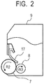
- FIG. 2 is a schematic configuration view for illustrating an example of a process cartridge using the developer carrying member according to this aspect as a developing member.
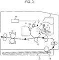
- FIG. 3 is a schematic configuration view for illustrating an example of an electrophotographic image forming apparatus having incorporated therein the process cartridge in a removable manner.
- the process cartridge illustrated in FIG. 2 includes a toner container 9, a developer carrying member 7, a developer-regulating member 17, and a developer-supplying member 8, and has such a configuration as to be removably mounted onto the main body of an electrophotographic image forming apparatus.
- an electrostatic latent image-bearing member 18, which is an image-bearing member having formed thereon an electrostatic latent image is rotated in a direction indicated by an arrow R1.
- the developer carrying member 7 rotates in a direction indicated by an arrow R2 to convey its developer to a developing region where the developer carrying member 7 and the electrostatic latent image-bearing member 18 face each other.
- the developer-supplying member 8 is in contact with the developer carrying member, and rotates in a direction indicated by an arrow R3 to supply the developer to the surface of the developer carrying member 7.
- a charging roller 6 serving as a charging member arranged so as to be capable of charging the electrostatic latent image-bearing member 18, a transfer member (transfer roller) 10, a cleaner container 11, a cleaning blade 12, a fixing unit 13, a pickup roller 14, and the like are arranged around the electrostatic latent image-bearing member 18.
- the electrostatic latent image-bearing member 18 is charged by the charging roller 6.
- a laser generator 16 applies laser light to the electrostatic latent image-bearing member 18 to perform exposure, and hence the electrostatic latent image corresponding to a target image is formed thereon.
- the electrostatic latent image on the electrostatic latent image-bearing member 18 is developed with the developer in the toner container 9 of the process cartridge serving as a developing unit to provide an image.
- a transfer material (paper) P is conveyed from a sheet-feeding portion 15 into the apparatus by the pickup roller 14 and the like, and the image is transferred onto the transfer material (paper) P by the transfer member (transfer roller) 10 brought into abutment with the electrostatic latent image-bearing member 18 through the transfer material (paper) P.
- the transfer material (paper) P having mounted thereon the image is conveyed to the fixing unit 13, and the developer is fixed onto the transfer material (paper) P.
- the developer remaining on the electrostatic latent image-bearing member 18 is scraped off by the cleaning blade 12, and is stored in the cleaner container 11.
- the developer-regulating member 17 is preferably brought into abutment with the developer carrying member 7 through the developer to regulate the thickness of a developer layer on the developer carrying member.
- a regulating blade may be suitably used as the developer-regulating member to be brought into abutment with the developer carrying member.
- a rubber elastic body such as a silicone rubber, a urethane rubber, or an NBR, a synthetic resin elastic body, such as polyethylene terephthalate, or a metal elastic body, such as a phosphor bronze plate or a SUS plate, may be used as a material for forming the above-mentioned regulating blade, and a composite thereof may also be used. Further, a structure obtained by bonding a charge-controlling material, such as a resin, a rubber, a metal oxide, or a metal, to an elastic support, such as a rubber, a synthetic resin, or a metal elastic body, may be used for the purpose of controlling the chargeability of the developer.
- a charge-controlling material such as a resin, a rubber, a metal oxide, or a metal
- the regulating blade is used so that its charge-controlling material portion may serve as a portion to be brought into abutment with the developer carrying member.
- Such regulating blade is particularly preferably a blade obtained by bonding the resin or the rubber to the metal elastic body.
- a product that can be easily charged to positive polarity such as a urethane rubber, a urethane resin, a polyamide resin, or a nylon resin, is preferred as such resin or rubber.
- the following materials for forming an NBR/hydrin elastic layer were mixed with a 6-liter pressure kneader (product name: TD6-15MDX, manufactured by Toshin Co., Ltd.) at a filling ratio of 70 vol% and a blade revolution number of 30 rpm for 16 minutes to provide a mixture 1.
- a primer (product name: METALOC U-20, manufactured by Toyokagaku Kenkyusho Co., Ltd.) was applied to a ground and aluminum-made cylindrical tube having an outer diameter of 13 mm and an arithmetic average roughness Ra of 0.2 ⁇ m, and was baked thereon to provide a substrate.
- the substrate was placed in a mold, and the mixture 2 was poured into a cavity formed in the mold. Subsequently, the mold was heated to heat the NBR/hydrin rubber at a temperature of 160°C for 40 minutes, thereby curing the rubber.
- the substrate having the cured NBR/hydrin rubber layer formed on its peripheral surface was removed from the mold.
- an elastic roller K-1 in which the NBR/hydrin elastic layer having a thickness of 0.5 mm and a diameter of 14 mm was formed on the outer periphery of the substrate was produced.
- a primer (product name: HAMATITE No. 40, manufactured by The Yokohama Rubber Co., Ltd.) was applied to a ground and aluminum-made cylindrical tube having an outer diameter of 13 mm and an arithmetic average roughness Ra of 0.2 ⁇ m, and was baked thereon to provide a substrate.
- the substrate was placed in a mold, and a urethane rubber composition obtained by mixing the following materials was poured into a cavity formed in the mold.
- the mold was heated to heat the urethane rubber at a temperature of 120°C for 75 minutes, thereby curing the rubber.
- the substrate having the cured urethane rubber layer formed on its peripheral surface was removed from the mold.
- an elastic roller K-2 in which the urethane rubber elastic layer having a thickness of 0.5 mm and a diameter of 14 mm was formed on the outer periphery of the substrate was produced.
- a synthesis example of an isocyanate group-terminated prepolymer that is a raw material for synthesizing the urethane resin of a surface layer is described.
- raw material polyols B-1 to B-3 to be used in the synthesis of the isocyanate group-terminated prepolymer were synthesized by the following methods.
- the reaction liquid was cooled to 100°C, and a pressure in the flask was reduced to 150 mmHg (20.0 kPa) over 1 hour. Subsequently, the pressure was reduced from 150 mmHg to 40 mmHg (5.3 kPa) over 30 minutes. Thus, a polyester oligomer was obtained.
- to copolymerize the polycarbonate 76.7 g (0.65 mol) of diethyl carbonate (manufactured by Mitsui Fine Chemicals, Inc.) and 1.0 mg of zinc acetate dihydrate (manufactured by Nacalai Tesque, Inc.) were added thereto, and the mixture was subjected to a reaction under reduced pressure. After the reaction had been performed for 2 hours, the raw material polyol B-1 was obtained.
- the raw material polyols B-2 and B-3 were each synthesized in the same manner as in the synthesis of the raw material polyol B-1 described above except that the raw materials to be used in the reactions and their mixing amounts were changed as shown in Table 1 below.
- Table 1 Raw material polyol No.
- Polymeric MDI (product name: MILLIONATE MR, manufactured by Tosoh Corporation) was prepared as a raw material isocyanate C-1 for preparing isocyanate group-terminated prepolymers to be described later by being caused to react with the above-mentioned raw material polyols.
- the mixture was subjected to a reaction at a temperature of 65°C for 2 hours.
- the resultant reaction mixture was cooled to room temperature to provide an isocyanate group-terminated prepolymer A-1 having a solid content of 50% and an isocyanate group content of 6.0 mass%.
- Isocyanate group-terminated prepolymers A-2 and A-3 were each obtained as a solution having a solid content of 50% in the same manner as in the synthesis of the isocyanate group-terminated prepolymer A-1 except that the kinds and mixing amounts of the raw material polyol and the raw material isocyanate to be used in the synthesis, and the reaction time were changed as shown in Table 2.
- the column "Isocyanate group concentration" shows a value when the solid content of an isocyanate group-terminated prepolymer is set to 100 mass%.
- Table 2 Isocyanate group-terminated prepolymer No.
- Raw material polyol Raw material isocyanate Reaction time (hours) Isocyanate group concentration (mass%) Kind Part(s) by mass Kind Part(s) by mass A-1 B-1 100.0
- Polymeric MDI "MILLIONATE MR" manufactured by Tosoh Corporation) 30.2 3.0 12.0
- Polyol compounds D-1 to D-3 shown in Table 3 below were prepared.
- Table 3 Polyol compound No. Product name Hydroxy value (mgKOH/g)
- D-1 TRIMETHYLOLETHANE manufactured by Tokyo Chemical Industry Co., Ltd.
- 1,648 D-3 KURARAY POLYOL P-2050 (manufactured by Kuraray Co., Ltd.) 56
- Binder resins E-1 to E-4 were produced according to such formulation as shown in the following table, and their SP values were measured.
- Table 4 Binder resin Isocyanate group-terminated prepolymer Polyol compound SP value No. Part(s) by mass No. Part(s) by mass E-1 A-1 95.4 D-1 4.6 10.1 E-2 A-2 95.4 D-2 4.6 11.0 E-3 A-1 96.9 D-1 3.1 9.2 E-4 A-3 60.6 D-3 39.4 8.3
- a paint F-1 for forming a surface layer was prepared.
- the paint F-1 was applied to a ground and aluminum-made conductive support of a cylindrical tube shape having an outer diameter of 14 mm ⁇ and a center line average roughness Ra of 0.2 ⁇ m by a spray method to form a resin coating layer thereon. Subsequently, the resin coating layer was cured through heating in a hot air drying furnace at 150°C for 30 minutes to form the surface layer (thickness: 10 ⁇ m) of the paint on the surface of the support. Thus, a developing roller No. H-1 according to Example 1 was produced.
- the developing roller H-1 was subjected to the following evaluations.
- the contents of electroconductive particles in the first region and second region of the surface layer were calculated as described below.
- the carbon black area ratios in the respective regions were calculated for each of the six sectional samples as described above, and the averages of the calculated values were adopted as the contents A1% and A2% of the electroconductive particles in the first region and the second region, respectively.
- Three conductive tapes each having a width of 12 mm were wound around the surface of the developing roller H-1 at intervals of 8 mm, and a conductive tape D2 positioned at the center out of the three conductive tapes, and the mandrel of the developing roller H-1 were used as main electrodes in the measurement of the volume resistivity of the roller, while two conductive tapes D1 and D3 outside the tape D2 were used as guard electrodes therein.
- the developing roller H-1 had been left to stand in an evaluation environment (having a temperature of 23°C and a relative humidity of 50%) for 12 hours, the measurement was performed under the environment.
- the measurement was performed with an AC impedance analyzer (an impedance analyzer Model 1260 and a dielectric constant-measuring interface Model 1296 manufactured by Solartron Analytical). An AC voltage of 100 mV was superimposed on a DC voltage of 0 V, and the complex impedance characteristics of the roller were measured for a frequency change from 1 MHz to 1 Hz. A resistance component was calculated by analyzing the results of the measurement with impedance analysis software ZView. The volume resistivity was calculated from the component and the shape of the sample that had been separately determined.
- Paints F-2 to F-9 for forming surface layers were each produced in the same manner as in Example 1 except that materials shown in each of Table 5 and Table 6 below were used as surface layer materials. Then, the respective paints were applied, dried, and heated in the same manner as in Example 1 to produce developing rollers H-2 to H-13 according to Examples 2 to 13.
- the developing rollers H-5 and H-6 according to Example 5 and Example 6 were produced by using the elastic rollers K-1 and K-2 produced in advance instead of the aluminum-made cylindrical tube of Example 1, respectively.
- a paint G-1 for forming a surface layer according to Comparative Example 1 was prepared in the same manner as in the method of preparing the paint for forming a surface layer according to Example 1.
- the paint for forming a surface layer was applied to the surface of the aluminum-made conductive support of a cylindrical tube shape, and was dried to form a surface layer in the same manner as in Example 1.
- a developing roller J-1 of Comparative Example 1 was produced.
- Paints G-2 to G-4 for forming surface layers were each produced in the same manner as in Comparative Example 1 except that materials shown in Table 7 below were used as surface layer materials. Then, each of the paints was applied to the aluminum-made conductive support of a cylindrical tube shape, dried, and heated in the same manner as in Comparative Example 1. Thus, developing rollers J-2 to J-4 according to Comparative Examples 2 to 4 were produced.
- Each of the developing rollers of Examples and Comparative Examples was evaluated by performing an endurance test for each of the following evaluation items as described below.
- the developing roller of a cartridge 37Y for a laser printer manufactured by Hewlett-Packard Company
- a laser printer product name: HP LaserJet Enterprise M609dn, manufactured by Hewlett-Packard Company
- the roller was subjected to endurance evaluations for a blotch image and the abrasion resistance of the surface layer in a low-temperature and low-humidity (L/L) environment having a temperature of 15°C and a humidity of 10%.
- L/L low-temperature and low-humidity
- the developing rollers H-2 to H-13 and the developing rollers J-1 to J-4 were similarly evaluated.
- the physical properties of the surface layers of the resultant developer carrying members, and the evaluation results of the developer carrying members are shown in Table 8 and Table 9.
- the developer carrying members of Examples provided satisfactory results in terms of both of image and durability.
- the surface of the developer carrying member after the endurance test was observed with a laser microscope (product name: VKX-100, manufactured by Keyence Corporation) at a magnification of 200, and the degree of its toner contamination was evaluated based on the following criteria.
- the area ratio of a contaminated portion with respect to the entirety of an observed image was calculated, and the calculation was performed for N images where N represented 12, followed by the evaluation of the average of the calculated results.
- the shaved amount of the thickness of the surface layer of the developer carrying member after the endurance test as compared to the thickness before the test was measured as follows: fixed points on the layer that had been observed in advance before the endurance were observed after the endurance again, and their surface shapes before and after the endurance were observed. In the measurement, the observation was performed with a laser microscope (product name: VKX-100, manufactured by Keyence Corporation) at a magnification of 50. N points where N represented 3 were used as the fixed points, and the shaved amount was calculated by averaging their respective deformation amounts.
Landscapes
- Physics & Mathematics (AREA)
- General Physics & Mathematics (AREA)
- Engineering & Computer Science (AREA)
- General Engineering & Computer Science (AREA)
- Mechanical Engineering (AREA)
- Dry Development In Electrophotography (AREA)
Abstract
Description
- The present disclosure is directed to a developer carrying member to be used in an electrophotographic apparatus, and a process cartridge and an electrophotographic image forming apparatus each including the developer carrying member.
- In an electrophotographic image forming apparatus, an electrophotographic photosensitive member (hereinafter sometimes referred to as "photosensitive member") is charged by a charging roller and exposed, and as a result, an electrostatic latent image is formed on the photosensitive member. Next, toner in a developer container is applied onto a developer carrying member by a toner-supplying roller and a toner-regulating member. Next, the toner is conveyed by the developer carrying member to a developing region. The electrostatic latent image on the photosensitive member is developed with the toner conveyed to the developing region in an abutting portion between the photosensitive member and the developer carrying member, or a portion close thereto. After that, the toner on the photosensitive member is transferred onto recording paper by transferring means, and is fixed by heat and a pressure, while the toner remaining on the photosensitive member is removed from the top of the photosensitive member by cleaning means.
- Incidentally, as the formation of an electrophotographic image is repeated, a so-called charge-up phenomenon in which the charge quantity of the toner carried on the outer surface of the developer carrying member becomes excessively high owing to its contact with the developer carrying member may occur. When the charge-up phenomenon occurs, the toner sticks onto the outer surface of the developer carrying member, and toner to be newly supplied thereonto is hardly charged, and hence the charged state of the toner becomes nonuniform to reduce image quality in some cases.
- In
Patent Literature 1, there is a disclosure of a developer carrying member having formed on its surface a film containing crystalline graphite, the crystalline graphite being exposed to the surface of the film. - PTL 1:
Japanese Patent Application Laid-Open No. H2-105181 - At least one aspect of the present disclosure is directed to providing a developer carrying member that can stably provide a high-quality image. Another aspect of the present disclosure is directed to providing a process cartridge conducive to the formation of a high-quality electrophotographic image. Another aspect of the present disclosure is directed to providing an electrophotographic image forming apparatus that can stably form a high-quality electrophotographic image.
- According to one aspect of the present disclosure, there is provided a developer carrying member including an electroconductive support and a surface layer in the stated order, the surface layer contains a binder resin and electroconductive particles, and a content of the electroconductive particles in a region from a surface of the surface layer opposite to an outer surface thereof on a side facing the electroconductive support to a depth of 150 nm is 1% or more and 25% or less, and wherein the surface layer has a volume resistivity of 1.0×10⁻² Ω·cm or more and 1.0×10² Ω·cm or less.
- According to another aspect of the present invention, there is provided a process cartridge removably mounted onto a main body of an electrophotographic apparatus, the process cartridge including at least: a toner container containing toner; and a developer carrying member configured to convey the toner, wherein the developer carrying member is the above-mentioned developer carrying member.
- According to another aspect of the present invention, there is provided an electrophotographic apparatus including at least: an electrophotographic photosensitive member; a charging member arranged so as to be capable of charging the electrophotographic photosensitive member; and a developer carrying member configured to supply toner to the electrophotographic photosensitive member, wherein the developer carrying member is the above-mentioned developer carrying member.
- According to one aspect of the present disclosure, there can be obtained the developer carrying member that can stably provide a high-quality electrophotographic image. According to another aspect of the present disclosure, there can be obtained the process cartridge conducive to the formation of a high-quality electrophotographic image. According to another aspect of the present disclosure, there can be obtained the electrophotographic image forming apparatus that can stably form a high-quality electrophotographic image.
-
- [
FIG. 1A ]
FIG. 1A is a conceptual view for illustrating an example of a developer carrying member of the present disclosure. - [
FIG. 1B ]
FIG. IB is a conceptual view for illustrating an example of the developer carrying member of the present disclosure. - [
FIG. 1C ]
FIG. 1C is a conceptual view for illustrating an example of the developer carrying member of the present disclosure. - [
FIG. 2 ]
FIG. 2 is a schematic configuration view for illustrating an example of a process cartridge of the present disclosure. - [
FIG. 3 ]
FIG. 3 is a schematic configuration view for illustrating an example of an electrophotographic apparatus of the present disclosure. - An investigation by the inventors has found that in the case of the developer carrying member according to
Patent Literature 1, the carrying member having formed on its surface the film containing the crystalline graphite so that the graphite may be exposed to its surface, toner is liable to stick to the toner-carrying surface (hereinafter sometimes referred to as "outer surface") of the developer carrying member. - This is probably because of the fact that the film containing the crystalline graphite so that the graphite may be exposed to its surface forms the outer surface of the developer carrying member, and hence a reflection force acting between the toner and the film becomes larger.
- An example of a force acting between the toner and the surface of the developer carrying member is the reflection force. The reflection force may be represented by the equation (A). That is, the reflection force is an electric force acting on the toner, which is positioned at a distance of "a" from the surface of the developer carrying member and has a charge of -q, in the case where it is assumed that a fictitious charge "q'", which is positioned in the surface of the developer carrying member at a distance of "a" from the surface and has a charge of +q, is present. A larger reflection force means a larger adhesive force of the toner to the surface of the developer carrying member, and as the distance "a" becomes smaller, the reflection force acting on the toner becomes larger. The reflection force may be a cause for the charge-up described above.
- [Math. 1]

- F: The reflection force between the toner and the developer carrying member
- "q": The charge
- "a": The distance between the charge and the surface of the developer carrying member
- ε0: A dielectric constant of vacuum
- εr: The relative dielectric constant of the developer carrying member
- As is apparent from the equation (A), as the absolute value of the charge "q" becomes larger, and as the distance "a" between the charge and the surface of the developer carrying member becomes smaller, the reflection force F becomes larger. In addition, as the relative dielectric constant εr of the developer carrying member becomes smaller, the reflection force F becomes smaller. Accordingly, the reflection force can be reduced by reducing the dielectric constant of the vicinity of the outer surface of the developer carrying member having a large influence on the reflection force. In general, the relative dielectric constant of an electroconductive particle is larger than that of a resin. Accordingly, a reduction in content of the electroconductive particles present near the outer surface of the developer carrying member may be effective in reducing the reflection force.
- Meanwhile, when the toner is excessively charged, the developer carrying member has a function of optimizing the charge of the toner by receiving the charge. The incorporation of a certain amount of the electroconductive particles into the vicinity of the outer surface of the developer carrying member in contact with the toner is effective in more sufficiently expressing the function.
- As described above, a configuration required for the developer carrying member to reduce the reflection force and a configuration required for the carrying member to suppress the charge-up of the toner are contrary to each other.
- In view of the foregoing, the inventors have made investigations with a view to obtaining a developer carrying member that can achieve both of a reduction in reflection force and the suppression of the charge-up of the toner at high levels. As a result, the inventors have found that a developer carrying member having the following configuration is conducive to the achievement of the object:
- a developer carrying member including an electroconductive support and a surface layer in the stated order, in which the surface layer contains a binder resin and electroconductive particles, and the content of the electroconductive particles in a region from the surface of the surface layer opposite to the outer surface thereof on a side facing the electroconductive support to a depth of 150 nm is 1% or more and 25% or less, and in which the surface layer has a volume resistivity of 1.0×10⁻² Ω·cm or more and 1.0×10² Ω·cm or less.
- That is, an investigation by the inventors has found that the content of the electroconductive particles in the region from the outer surface of the developer carrying member to a depth of 150 nm mainly dominates the reflection force between the developer carrying member and the toner present on the outer surface. In addition, the inventors have found that the setting of the content of the electroconductive particles in the region to 1% or more and 25% or less can reduce the reflection force, and hence can suppress the sticking of the toner.
- In addition, the inventors have found that when the volume resistivity of the surface layer for forming the outer surface of the developer carrying member is set to 1.0×10⁻² Ω·cm or more and 1.0×10² Ω·cm or less on condition that the above-mentioned requirement is satisfied, the charge-up of the toner can also be suppressed.
- Sectional views of a roller-shaped developer carrying member according to one aspect of the present disclosure in a direction perpendicular to its shaft direction are illustrated in
FIG. 1A to FIG. 1C . As illustrated inFIG. 1A , a developingroller 1 has asurface layer 3 formed on the outer peripheral surface of a columnar or hollow cylindricalconductive support 2. - As another configuration of the
developer carrying member 1, as illustrated inFIG. 1B , the carrying member includes the columnar or hollow cylindricalconductive support 2 and thesurface layer 3, and further includes anelastic layer 4 serving as an option between theelectroconductive support 2 and thesurface layer 3. That is, the developer carrying member includes the electroconductive support, the elastic layer serving as an option on the electroconductive support, and the surface layer on the elastic layer. Further, the carrying member may be a three-layer structure in which anintermediate layer 5 is arranged between thesurface layer 3 and theelastic layer 4 as illustrated inFIG. 1C , or a multilayer structure in which the plurality ofintermediate layers 5 are arranged therebetween. A known intermediate layer for a developer carrying member may be used as the intermediate layer. - The electroconductive support functions as the electrode and support member of the developer carrying member, and includes, for example, any one of the following conductive materials: a metal or an alloy, such as aluminum, a copper alloy, or stainless steel; iron subjected to plating treatment with chromium or nickel; and a synthetic resin having conductivity. The electroconductive support may be solid or hollow. In addition, the electroconductive support may be subjected to surface treatment or surface application, such as alumite treatment or primer application, for improving adhesiveness between the electroconductive support and the surface layer.
- When the developer carrying member and any other member, such as a photosensitive member or a developer-regulating blade, are brought into abutment with each other, the elastic layer serving as an option imparts elasticity to the developer carrying member for facilitating the formation of a nip having a predetermined width.
- A material known as a material for an elastic layer or a material that may be utilized for an elastic layer may be used as a material for forming the elastic layer. In normal cases, the elastic layer is preferably formed of a molded body of a rubber material. Examples of the rubber material include the following materials.
- An ethylene-propylene-diene copolymer rubber (EPDM), an acrylonitrile-butadiene rubber (NBR), a chloroprene rubber (CR), a natural rubber (NR), an isoprene rubber (IR), a styrene-butadiene rubber (SBR), a fluorine rubber, a silicone rubber, an epichlorohydrin rubber, a hydrogenated NBR, and a urethane rubber.
- Those materials may be used alone or as a mixture thereof.
- Various additives, such as a conductivity-imparting agent, a non-electroconductive filler, a crosslinking agent, and a catalyst, are appropriately blended into the
elastic layer 4. Fine particles of carbon black, of a conductive metal, such as aluminum or copper, or of a conductive metal oxide, such as zinc oxide, tin oxide, or titanium oxide, may be used as the conductivity-imparting agent. At least one kind of those agents may be used. Of those, the carbon black is particularly preferred because the carbon black is relatively easily available and provides satisfactory conductivity. When the carbon black is used as the conductivity-imparting agent, the carbon black is preferably blended in an amount of 2 parts by mass or more and 50 parts by mass or less with respect to 100 parts by mass of the rubber material in the material for forming the elastic layer. - Examples of the non-electroconductive filler include silica, quartz powder, titanium oxide, zinc oxide, and calcium carbonate. At least one kind of those fillers may be used. Examples of the crosslinking agent include di-t-butyl peroxide, 2,5-dimethyl-2,5-di(t-butylperoxy)hexane, and dicumyl peroxide. At least one kind of those agents may be used.
- The content of the electroconductive particles in the region from the surface (hereinafter sometimes referred to as "first surface") of the surface layer opposite to the surface (hereinafter sometimes referred to as "second surface") thereof on the side facing the electroconductive support to a depth of 150 nm is 1% or more and 25% or less. The first surface is a surface, which forms the outer surface of the developer carrying member, and which is brought into contact with toner and has formed thereon the layer of the toner in an electrophotographic image-forming step. The region from the first surface of the surface layer to a depth of 150 nm is hereinafter sometimes simply referred to as "first region."
- When the content of the electroconductive particles in the first region of the surface layer is 1% or more and 25% or less, charge-imparting performance to the toner can be maintained, and the adhesion of the toner to the first surface can be significantly suppressed.
- In addition, when the content of the electroconductive particles in the first region is represented by A1 (%), and the content of the electroconductive particles in a region (hereinafter sometimes referred to as "second region") from a depth of 150 nm from the first surface of the surface layer to a depth of 300 nm therefrom is represented by A2 (%), the surface layer preferably satisfies a relationship of A1<A2.
- When the toner is carried on the first surface, a distance between each of the electroconductive particles in the second region and the toner on the first surface is large, and hence their contribution to the reflection force F is small.
- Meanwhile, the surface layer needs to have predetermined conductivity so that a charge can be flowed from the first surface toward the second surface for suppressing excessive charging of the toner. When the A2 is set to be larger than the A1, the volume resistivity of the surface layer can be reduced while the reflection force F is suppressed from increasing.
- A method of calculating the contents of the electroconductive particles in the first region and the second region is described below.
- (i) The surface layer of the developer carrying member is cut with a razor in a direction perpendicular to the electroconductive support, and sectional samples of thin slices each having a thickness of 1.5 µm are produced from the layer with a microtome in an environment at a temperature of -120°C established by using liquid nitrogen. The sectional samples are collected from a total of six sites formed of: three sites for dividing the surface layer in four equal parts in the longitudinal direction of the developer carrying member; and three sites obtained by rotating the sites by 180° each.
- (ii) A secondary electron image is obtained for each of the sectional samples with a scanning electron microscope (e.g., a microscope available under the product name "Ultra-Plus" from Carl Zeiss AG) under the following conditions. Observation conditions: a magnification of 20,000, an acceleration voltage of 1.0 kV (section), and a work D of 3.5 mm
- (iii) The resultant secondary electron image is binarized with image processing software (e.g., "Image J," open source) by Otsu's method, and the area ratio of carbon black serving as the electroconductive particles in each of a rectangular region of the sectional sample measuring 150 nm in a depth direction from the first surface of the surface layer by 5,000 nm in a lateral direction, and a rectangular region thereof ranging from a depth of 150 nm from the first surface of the surface layer to a depth of 300 nm therefrom, and measuring 5,000 nm in the lateral direction is calculated with image processing software (product name: Luzex-AP, manufactured by Nireco Corporation).
- The carbon black area ratios in the respective regions are calculated for each of the six sectional samples as described above, and the averages of the calculated values are adopted as the contents A1% and A2% of the electroconductive particles in the first region and the second region, respectively.
- In addition, the volume resistivity of the developer carrying member is 1.0×10⁻² Ω·cm or more and 1.0×10² Ω·cm or less. With such configuration, the charge-up of the toner to be carried on the first surface can be effectively suppressed. A method of measuring the volume resistivity of the developer carrying member is described below.
- Three conductive tapes each having a width of 12 mm are wound around the surface of the developer carrying member at intervals of 8 mm, and a conductive tape D2 positioned at the center out of the three conductive tapes, and the mandrel of the developer carrying member are used as main electrodes in the measurement, while two conductive tapes D1 and D3 outside the tape D2 are used as guard electrodes therein. After the developer carrying member has been left to stand in an evaluation environment (having a temperature of 23°C and a relative humidity of 50%) for 12 hours, the measurement is performed under the environment. The measurement is performed with an AC impedance analyzer (an impedance analyzer Model 1260 and a dielectric constant-measuring interface Model 1296 manufactured by Solartron Analytical). An AC voltage of 100 mV is superimposed on a DC voltage of 0 V, and the complex impedance characteristics of the carrying member are measured for a frequency change from 1 MHz to 1 Hz.
- A resistance component is calculated by analyzing the results of the measurement with impedance analysis software ZView. The volume resistivity is calculated from the component and the shape of the sample that has been separately determined.
- Although a method of forming the surface layer is not particularly limited, examples thereof include spraying with, immersion in, and roll coating with a paint. Such a dip coating method as described in
Japanese Patent Application Laid-Open No. 57-5047 - At the time of the production of the surface layer according to this aspect, a raw material having a solubility parameter (SP) value of 9.0 or more is preferably selected as a raw material for the binder resin in the surface layer. The inventors have assumed a reason for the foregoing to be as described below.
- When a paint for forming the surface layer containing the raw material for the binder resin and the electroconductive particles is applied to the outer surface of the electroconductive support to form a coating film of the paint, in the case where the paint contains the raw material for the binder resin having a SP value of 9.0 or more, the wettability of the paint to the electroconductive support is low, and hence a force for keeping the raw material for the binder resin away from the electroconductive support acts in the coating film. In that case, the raw material for the binder resin in the coating film is easily biased toward the surface of the coating film on a side distant from the electroconductive support. As a result, in the coating film, the ratio of the electroconductive particles on the side distant from the electroconductive support becomes relatively lower than that on a side close to the electroconductive support. In addition, the curing of the coating film in such state may form the surface layer according to this aspect.
- Accordingly, the wettability of the raw material for the binder resin having a SP value of 9.0 or more to the application target surface to which the paint is applied only needs to be poor. Accordingly, as long as the condition is satisfied, the application target surface does not need to be the outer surface of the electroconductive support, and may be, for example, the outer surface (surface opposite to the electroconductive support) of the elastic layer formed on the electroconductive support.
- For example, a case in which the surface layer contains a urethane resin as the binder resin is described. In this case, the developer carrying member according to this aspect may be obtained by: directly applying, as the paint for forming the surface layer, a paint containing a polyisocyanate and a polyol, and having a SP value of 9.0 or more onto an electroconductive support whose outer surface contains at least one selected from aluminum and alumina to form a coating film of the paint; and then curing the coating film. In the developer carrying member thus formed, the surface layer is directly formed on the surface of the electroconductive support, and the surface layer contains a cured product of the paint for forming the surface layer containing the polyisocyanate, the polyol, and the electroconductive particles.
- A method of measuring the SP value of the raw material for the binder resin is described by taking a case in which the binder resin is the urethane resin as an example. A raw material for the urethane resin is a mixture of the polyisocyanate and the polyol. Accordingly, a mixture containing the polyisocyanate and the polyol at the same quantity ratio as a quantity ratio between the polyisocyanate and the polyol in the paint for forming the surface layer is prepared. 0.5 Gram of the mixture is loaded into a 100-milliliter beaker, and 10 ml of the following good solvent is added with a volumetric pipette to dissolve the mixture, thereby preparing a titration mixture.
- Next, the following poor solvent is dropped into the titration mixture with a 50-milliliter burette, and the volume fraction (ϕpl) of the poor solvent at the time point when turbidity occurs is recorded. In addition, deionized water is dropped into the titration mixture, and the volume fraction (ϕph) of the deionized water at the time point when turbidity occurs is recorded. The measurement is performed at a liquid temperature of 20°C.
- Good solvent: methyl ethyl ketone (SP value obtained by Hansen measurement: δg=9.77)
- Poor solvent: hexane (SP value: δpl=7.24), deionized water (SP value: δph=23.50)
- The SP values (δml and δmh) of the mixed forms at the turbidity points each produced by dropping the poor solvent or the deionized water may be represented as the volume averages of the SP values of the poor solvent and the good solvent as represented by the
following equation 1 andequation 2, respectively. In addition, the SP value δpoly of the mixture is a value intermediate between the δml and the δmh, and hence may be determined by theequation 3.


- Although the binder resin is not particularly limited, specific examples thereof may include a polyurethane resin, an acrylic resin, a urea resin, a melamine resin, an alkyd resin, a phenol resin, a polyamide resin, an epoxy resin, and a polyester resin.
- Of those, the polyurethane resin or the polyamide resin is preferred from the viewpoint of the ease with which a resin having the above-mentioned SP value is synthesized. Further, a urethane resin may be particularly suitably used because the resin has a low dielectric constant and easily provides satisfactory abrasion resistance.
- The urethane resin is obtained by causing a polyisocyanate and a polyol to react with each other. In addition, high-polarity materials are preferably selected so that a SP value of 9.0 or more may be obtained.
- A polyisocyanate known as a polyisocyanate for synthesizing a urethane resin or a polyisocyanate that may be used for synthesizing a urethane resin may be used as the polyisocyanate. Examples of the polyisocyanate include isocyanate compounds including: aliphatic polyisocyanates, such as ethylene diisocyanate and 1,6-hexamethylene diisocyanate (HDI); alicyclic polyisocyanates, such as isophorone diisocyanate (IPDI), cyclohexane-1,3-diisocyanate, and cyclohexane-1,4-diisocyanate; aromatic isocyanates, such as 2,4-tolylene diisocyanate, 2,6-tolylene diisocyanate (TDI), 4,4'-diphenylmethane diisocyanate (MDI), polymeric diphenylmethane diisocyanate, xylylene diisocyanate, and naphthalene diisocyanate; and copolymerized products, isocyanurate bodies, TMP adducts, biuret bodies, and block bodies thereof. At least one kind of those materials may be used.
- A polyol (polycarbonate polyol/polyether polyol/polyester polyol) known as a polyol for synthesizing a urethane resin or a polyol that may be used for synthesizing a urethane resin may be used as the polyol. The polyol has a plurality of hydroxy groups in a molecule thereof, and the hydroxy groups react with the polyisocyanate.
- At least one kind selected from a polycarbonate diol and a polycarbonate triol may be used as the polycarbonate polyol. Of those, the polycarbonate diol is preferred. An example of the polycarbonate diol may be such a polycarbonate diol that both terminals of a structure obtained by repeated bonding of alkylene chains each of which may have a moiety for forming part of a cyclic hydrocarbon structure through carbonate bonds are hydroxy groups.
- Examples of the alkylene chain of the polycarbonate diol that may have a moiety for forming part of the cyclic hydrocarbon structure may include: a linear or branched alkylene group having 3 or more and 8 or less carbon atoms; and an alkylene group having 4 or more and 8 or less carbon atoms, the group including a cyclic hydrocarbon structure having 4 or more and 6 or less carbon atoms.
- Examples of the polycarbonate diol include the following polycarbonate diols: polynonamethylene carbonate diol, poly(2-methyl-octamethylene)carbonate diol, polyhexamethylene carbonate diol, polypentamethylene carbonate diol, poly(3-methylpentamethylene)carbonate diol, polytetramethylene carbonate diol, polytrimethylene carbonate diol, poly(1,4-cyclohexanedimethylenecarbonate) diol, poly(2-ethyl-2-butyl-trimethylene)carbonate diol, and random or block copolymers thereof. At least one kind of those polycarbonate diols may be used.
- Examples of a polyester-polycarbonate-copolymerized polyol include the following copolymers: a copolymer obtained by subjecting the above-mentioned polycarbonate polyol to polycondensation with a lactone, such as ε-caprolactone; and a copolymer of the polycarbonate polyol and a polyester obtained by subjecting an alkanediol and a dicarboxylic acid to polycondensation. Examples of the alkanediol for forming the polyester may include alkanediols each having 4 to 6 carbon atoms, such as 1,4-butanediol, 1,5-pentanediol, 1,6-hexanediol, 3-methylpentanediol, and neopentyl glycol. At least one kind of those alkanediols may be used.
- In addition, examples of the dicarboxylic acid may include adipic acid, sebacic acid, suberic acid, glutaric acid, and pimelic acid. At least one kind of those acids may be used.
- The polycarbonate polyol may be synthesized by a known method. The polycarbonate polyol may be obtained by, for example, a dehydrochlorination reaction between a low-molecular weight alcohol having 1 to 8 carbon atoms to be used in the synthesis of a polyester polyol and phosgene, or an ester exchange reaction between the low-molecular weight alcohol and dimethyl carbonate, diethyl carbonate, diphenyl carbonate, or the like.
- In addition, the polyester-polycarbonate-copolymerized polyol may be obtained by a method including causing a carbonate compound for copolymerizing a polycarbonate to react with a polyester oligomer obtained by causing a diol and a dicarboxylic acid to react with each other.
- An example of the diol to be used in the method may be a diol having an alkylene chain that may have a cyclic structure. Examples of the diol having an alkylene chain that may have a moiety for forming part of a cyclic structure may include 1,3-propanediol, 1,4-butanediol, 1,6-hexanediol, 1,4-bis(hydroxymethyl)cyclohexane, 1,4-bis(hydroxyethyl)cyclohexane, 3-methyl-1,5-pentanediol, 1,4-benzenedimethanol, and 1,8-octanediol. At least one kind of those diols may be used.
- Examples of the dicarboxylic acid in the above-mentioned method may include adipic acid, sebacic acid, suberic acid, glutaric acid, and pimelic acid. At least one kind of those acids may be used.
- A carbonic acid ester of a lower alcohol having 1 to 3 carbon atoms may be used as the carbonate compound in the above-mentioned method. Examples of the carbonic acid ester may include dimethyl carbonate and diethyl carbonate.
- Examples of the polyether polyol include polyethylene glycol, polypropylene glycol, and polytetramethylene glycol.
- In addition, an example of a polyester polyol free of any carbonate bond is a polyester polyol obtained by a condensation reaction between a diol component, such as 1,4-butanediol, 3-methyl-1,4-pentanediol, or neopentyl glycol, or a triol component, such as trimethylolpropane, and a dicarboxylic acid, such as adipic acid, phthalic anhydride, terephthalic acid, or hexahydroxyphthalic acid. The polyether polyol and the polyester polyol may each be provided as a prepolymer whose chain has been extended with an isocyanate, such as 2,4-tolylene diisocyanate (TDI), 1,4-diphenylmethane diisocyanate (MDI), or isophorone diisocyanate (IPDI), in advance as required.
- The ratio (L/M) of the number (L) of isocyanate groups to the number (M) of hydroxy groups in the urethane resin is preferably from 1.0 to 2.0. The ratio L/M is preferably 2.0 or less because as the ratio L/M becomes smaller, the SP value of the resin becomes larger. Meanwhile, when the ratio L/M is set to 1.0 or more, the amount of an unreacted component of the polyol component can be reduced, and hence the film formability of the paint is hardly impaired.
- The thickness of the surface layer preferably falls within the range of from 5.0 µm or more to 50.0 µm or less. When the thickness is 5.0 µm or more, the surface layer can uniformly cover the entirety of the surface of the electroconductive support. Accordingly, the electroconductive support is prevented from being partially exposed, and hence a triboelectric charge can be uniformly imparted to the developer of the developer carrying member. In addition, when the thickness is 50.0 µm or less, it becomes easier to stably control the surface roughness of the layer.
- A blending agent, a conductivity-imparting agent, a non-electroconductive filler, a crosslinking agent, or a catalyst may be added to the surface layer. Examples of the blending agent include a filler, a softening agent, a processing aid, a tackifier, an antitack agent, and a foaming agent to be generally used in resins. Examples of the non-electroconductive filler include silica, quartz powder, titanium oxide, and calcium carbonate. Although the crosslinking agent is not particularly limited, examples thereof include tetraethoxysilane, di-t-butyl peroxide, 2,5-dimethyl-2,5-di(t-butylperoxy)hexane, and dicumyl peroxide.
- Carbon black, conductive metal particles, such as aluminum particles and copper, and conductive metal oxide particles, such as zinc oxide, tin oxide, and titanium oxide, may be used as the electroconductive particles. Those particles may be used alone or as a mixture thereof. Of those, the carbon black is preferred because satisfactory electron conductivity is obtained. In addition, when the urethane resin is used as the binder resin, acidic carbon black having a pH value of 7.0 or less out of various kinds of the carbon black may be particularly suitably used. This is because of the following reason. The acidic carbon black has satisfactory dispersibility in the paint for forming the surface layer containing the polyisocyanate and the polyol that are raw materials for the urethane resin. Accordingly, the migration of the raw materials for the binder resin from a side close to the application target surface to a side distant from the application target surface in the coating film at the time of the application of the paint to the application target surface is hardly inhibited, and hence the surface layer according to this aspect is easily formed.
- When the carbon black is used as the electroconductivity-imparting agent, the carbon black is preferably blended in an amount of 1 part by mass or more and 50 parts by mass or less with respect to 100 parts by mass of the binder resin materials in the paint for forming the surface layer.
- When the surface layer of the developer carrying member is required to have a surface roughness, fine particles for roughness control may be added to the surface layer. The volume-average particle diameter of the fine particles for roughness control is preferably from 3 µm to 20 µm because a developer carrying member having an excellent toner-conveying ability is obtained. In addition, the amount of the fine particles to be added to the surface layer is preferably from 1 part to 50 parts with respect to 100 parts by mass of the resin solid content of the surface layer because the effects of the present disclosure are not impaired. Fine particles of a polyurethane resin, a polyester resin, a polyether resin, a polyamide resin, an acrylic resin, or a phenol resin may be used as the fine particles for roughness control.
- The developer carrying member according to this aspect may be applied to any one of, for example, a noncontact-type developing apparatus and a contact-type developing apparatus each using a magnetic one-component developer or a nonmagnetic one-component developer, and a developing apparatus using a two-component developer.
- A process cartridge and an electrophotographic image forming apparatus according to one aspect of the present disclosure are described in detail with reference to the drawings.
FIG. 2 is a schematic configuration view for illustrating an example of a process cartridge using the developer carrying member according to this aspect as a developing member. In addition,FIG. 3 is a schematic configuration view for illustrating an example of an electrophotographic image forming apparatus having incorporated therein the process cartridge in a removable manner. - The process cartridge illustrated in
FIG. 2 includes atoner container 9, adeveloper carrying member 7, a developer-regulatingmember 17, and a developer-supplyingmember 8, and has such a configuration as to be removably mounted onto the main body of an electrophotographic image forming apparatus. InFIG. 3 , an electrostatic latent image-bearingmember 18, which is an image-bearing member having formed thereon an electrostatic latent image, is rotated in a direction indicated by an arrow R1. Thedeveloper carrying member 7 rotates in a direction indicated by an arrow R2 to convey its developer to a developing region where thedeveloper carrying member 7 and the electrostatic latent image-bearingmember 18 face each other. In addition, the developer-supplyingmember 8 is in contact with the developer carrying member, and rotates in a direction indicated by an arrow R3 to supply the developer to the surface of thedeveloper carrying member 7. - A charging
roller 6 serving as a charging member arranged so as to be capable of charging the electrostatic latent image-bearingmember 18, a transfer member (transfer roller) 10, acleaner container 11, acleaning blade 12, a fixingunit 13, apickup roller 14, and the like are arranged around the electrostatic latent image-bearingmember 18. The electrostatic latent image-bearingmember 18 is charged by the chargingroller 6. Then, alaser generator 16 applies laser light to the electrostatic latent image-bearingmember 18 to perform exposure, and hence the electrostatic latent image corresponding to a target image is formed thereon. The electrostatic latent image on the electrostatic latent image-bearingmember 18 is developed with the developer in thetoner container 9 of the process cartridge serving as a developing unit to provide an image. The development performed here is so-called reversal development in which the exposed portion is developed with the developer. A transfer material (paper) P is conveyed from a sheet-feedingportion 15 into the apparatus by thepickup roller 14 and the like, and the image is transferred onto the transfer material (paper) P by the transfer member (transfer roller) 10 brought into abutment with the electrostatic latent image-bearingmember 18 through the transfer material (paper) P. The transfer material (paper) P having mounted thereon the image is conveyed to the fixingunit 13, and the developer is fixed onto the transfer material (paper) P. In addition, the developer remaining on the electrostatic latent image-bearingmember 18 is scraped off by thecleaning blade 12, and is stored in thecleaner container 11. - The developer-regulating
member 17 is preferably brought into abutment with thedeveloper carrying member 7 through the developer to regulate the thickness of a developer layer on the developer carrying member. A regulating blade may be suitably used as the developer-regulating member to be brought into abutment with the developer carrying member. - A rubber elastic body, such as a silicone rubber, a urethane rubber, or an NBR, a synthetic resin elastic body, such as polyethylene terephthalate, or a metal elastic body, such as a phosphor bronze plate or a SUS plate, may be used as a material for forming the above-mentioned regulating blade, and a composite thereof may also be used. Further, a structure obtained by bonding a charge-controlling material, such as a resin, a rubber, a metal oxide, or a metal, to an elastic support, such as a rubber, a synthetic resin, or a metal elastic body, may be used for the purpose of controlling the chargeability of the developer. In this case, the regulating blade is used so that its charge-controlling material portion may serve as a portion to be brought into abutment with the developer carrying member. Such regulating blade is particularly preferably a blade obtained by bonding the resin or the rubber to the metal elastic body. A product that can be easily charged to positive polarity, such as a urethane rubber, a urethane resin, a polyamide resin, or a nylon resin, is preferred as such resin or rubber.
- Specific Examples and Comparative Examples are described below.
- The following materials for forming an NBR/hydrin elastic layer were mixed with a 6-liter pressure kneader (product name: TD6-15MDX, manufactured by Toshin Co., Ltd.) at a filling ratio of 70 vol% and a blade revolution number of 30 rpm for 16 minutes to provide a
mixture 1. - Acrylonitrile-butadiene rubber (product name: N230SV, manufactured by JSR Corporation): 60 parts by mass
- Epichlorohydrin rubber (product name: EPION 310, manufactured by Osaka Soda Co., Ltd.): 40 parts by mass
- Zinc stearate: 1 part by mass
- Zinc oxide: 5 parts by mass
- Calcium carbonate (product name: NANOX #30, manufactured by Maruo Calcium Co., Ltd.): 20 parts by mass
- Carbon black (product name: TOKABLACK #7400, manufactured by Tokai Carbon Co., Ltd.): 40 parts by mass
- Next, the following materials were subjected to transverse crosscutting with open rolls each having a roll diameter of 12 inches (0.30 m) at a front roll revolution number of 10 rpm, a rear roll revolution number of 8 rpm, and a roll interval of 2 mm a total of 20 times. After that, the resultant was subj ected to
tight milling 10 times while the roll interval was set to 0.5 mm. Thus, amixture 2 was obtained. - Mixture 1: 200 parts by mass
- Sulfur: 1.2 parts by mass
- Tetrabenzylthiuram disulfide (product name: NOCCELER TBzTD, manufactured by Ouchi Shinko Chemical Industrial Co., Ltd.): 4.5 parts by mass
- A primer (product name: METALOC U-20, manufactured by Toyokagaku Kenkyusho Co., Ltd.) was applied to a ground and aluminum-made cylindrical tube having an outer diameter of 13 mm and an arithmetic average roughness Ra of 0.2 µm, and was baked thereon to provide a substrate. The substrate was placed in a mold, and the
mixture 2 was poured into a cavity formed in the mold. Subsequently, the mold was heated to heat the NBR/hydrin rubber at a temperature of 160°C for 40 minutes, thereby curing the rubber. The substrate having the cured NBR/hydrin rubber layer formed on its peripheral surface was removed from the mold. Thus, an elastic roller K-1 in which the NBR/hydrin elastic layer having a thickness of 0.5 mm and a diameter of 14 mm was formed on the outer periphery of the substrate was produced. - The following materials were mixed, and were caused to react with each other at 175°C for 12 hours. After that, the resultant was subjected to a reaction under a reduced pressure of 10 mmHg (1.3 kPa) at 210°C for 12 hours to provide a condensation-polymerized diol for producing a urethane elastic layer.
- Raw material diol; 3-methyl-1,5-pentanediol (manufactured by Tokyo Chemical Industry Co., Ltd.): 100 parts by mass
- Dibasic acid; adipic acid (manufactured by Tokyo Chemical Industry Co., Ltd.): 108.3 parts by mass
- A primer (product name: HAMATITE No. 40, manufactured by The Yokohama Rubber Co., Ltd.) was applied to a ground and aluminum-made cylindrical tube having an outer diameter of 13 mm and an arithmetic average roughness Ra of 0.2 µm, and was baked thereon to provide a substrate. The substrate was placed in a mold, and a urethane rubber composition obtained by mixing the following materials was poured into a cavity formed in the mold.
- Isocyanate (product name: DURANATE TPA-100, manufactured by Asahi Kasei Corporation): 7.37 parts by mass
- Diol for producing a urethane elastic layer: 100 parts by mass
- Quaternary ammonium salt (product name: TETRABUTYLAMMONIUM BROMIDE, manufactured by Tokyo Chemical Industry Co., Ltd.): 0.20 part by mass
- Subsequently, the mold was heated to heat the urethane rubber at a temperature of 120°C for 75 minutes, thereby curing the rubber. The substrate having the cured urethane rubber layer formed on its peripheral surface was removed from the mold. Thus, an elastic roller K-2 in which the urethane rubber elastic layer having a thickness of 0.5 mm and a diameter of 14 mm was formed on the outer periphery of the substrate was produced.
- A synthesis example of an isocyanate group-terminated prepolymer that is a raw material for synthesizing the urethane resin of a surface layer is described. First, raw material polyols B-1 to B-3 to be used in the synthesis of the isocyanate group-terminated prepolymer were synthesized by the following methods.
- 100.0 Grams (0.50 mol) of adipic acid (manufactured by Tokyo Chemical Industry Co., Ltd.) serving as a dicarboxylic acid, 87.0 g (1.14 mol) of 1,3-propanediol (manufactured by Tokyo Chemical Industry Co., Ltd.) serving as a diol, and 20.0 mg of a tetra-n-butyl orthotitanate tetramer (manufactured by Tokyo Chemical Industry Co., Ltd.) were loaded into a three-necked flask including a stirring machine and a temperature gauge, and were caused to react with each other under a nitrogen atmosphere at 160°C for 4 hours.
- Next, under the nitrogen atmosphere, the reaction liquid was cooled to 100°C, and a pressure in the flask was reduced to 150 mmHg (20.0 kPa) over 1 hour. Subsequently, the pressure was reduced from 150 mmHg to 40 mmHg (5.3 kPa) over 30 minutes. Thus, a polyester oligomer was obtained. Next, to copolymerize the polycarbonate, 76.7 g (0.65 mol) of diethyl carbonate (manufactured by Mitsui Fine Chemicals, Inc.) and 1.0 mg of zinc acetate dihydrate (manufactured by Nacalai Tesque, Inc.) were added thereto, and the mixture was subjected to a reaction under reduced pressure. After the reaction had been performed for 2 hours, the raw material polyol B-1 was obtained.
- The raw material polyols B-2 and B-3 were each synthesized in the same manner as in the synthesis of the raw material polyol B-1 described above except that the raw materials to be used in the reactions and their mixing amounts were changed as shown in Table 1 below.
Table 1 Raw material polyol No. Dicarboxylic acid Diol Diethyl carbonate Hydroxy value (mgKOH/g) Kind Part(s) by mass Kind Part(s) by mass Kind Part(s) by mass B-1 Adipic acid (manufactured by Tokyo Chemical Industry Co., Ltd.) 100.0 1,3-Propanediol (manufactured by Tokyo Chemical Industry Co., Ltd.) 110.0 Diethyl carbonate (manufactured by Mitsui Fine Chemicals, Inc.) 113.0 56.0 B-2 Adipic acid (manufactured by Tokyo Chemical Industry Co., Ltd.) 100.0 Diethylene glycol (manufactured by Tokyo Chemical Industry Co., Ltd.) 175.0 136.0 56.0 B-3 Sebacic acid (manufactured by Tokyo Chemical Industry Co., Ltd.) 100.0 1,3-Propanediol (manufactured by Tokyo Chemical Industry Co., Ltd.) 97.0 91.6 56.0 - Polymeric MDI (product name: MILLIONATE MR, manufactured by Tosoh Corporation) was prepared as a raw material isocyanate C-1 for preparing isocyanate group-terminated prepolymers to be described later by being caused to react with the above-mentioned raw material polyols.
- Under a nitrogen atmosphere, 30.8 parts by mass of the raw material isocyanate C-1 was dissolved in methyl ethyl ketone (hereinafter referred to as "MEK") in a reaction vessel so that the final solid content became 50%. After that, 100.0 parts by mass of the raw material polyol B-1 was gradually dropped into the solution while a temperature in the reaction vessel was held at 65°C.
- After the completion of the dropping, the mixture was subjected to a reaction at a temperature of 65°C for 2 hours. The resultant reaction mixture was cooled to room temperature to provide an isocyanate group-terminated prepolymer A-1 having a solid content of 50% and an isocyanate group content of 6.0 mass%.
- Isocyanate group-terminated prepolymers A-2 and A-3 were each obtained as a solution having a solid content of 50% in the same manner as in the synthesis of the isocyanate group-terminated prepolymer A-1 except that the kinds and mixing amounts of the raw material polyol and the raw material isocyanate to be used in the synthesis, and the reaction time were changed as shown in Table 2. The column "Isocyanate group concentration" shows a value when the solid content of an isocyanate group-terminated prepolymer is set to 100 mass%.
Table 2 Isocyanate group-terminated prepolymer No. Raw material polyol Raw material isocyanate Reaction time (hours) Isocyanate group concentration (mass%) Kind Part(s) by mass Kind Part(s) by mass A-1 B-1 100.0 Polymeric MDI "MILLIONATE MR" (manufactured by Tosoh Corporation) 30.2 3.0 12.0 A-2 B-2 100.0 39.8 2.0 14.1 A-3 B-3 100.0 19.8 2.0 9.8 - Polyol compounds D-1 to D-3 shown in Table 3 below were prepared.
Table 3 Polyol compound No. Product name Hydroxy value (mgKOH/g) D-1 TRIMETHYLOLETHANE (manufactured by Tokyo Chemical Industry Co., Ltd.) 1,400 D-2 PENTAERYTHRITOL (manufactured by Tokyo Chemical Industry Co., Ltd.) 1,648 D-3 KURARAY POLYOL P-2050 (manufactured by Kuraray Co., Ltd.) 56 - Binder resins E-1 to E-4 were produced according to such formulation as shown in the following table, and their SP values were measured.
Table 4 Binder resin Isocyanate group-terminated prepolymer Polyol compound SP value No. Part(s) by mass No. Part(s) by mass E-1 A-1 95.4 D-1 4.6 10.1 E-2 A-2 95.4 D-2 4.6 11.0 E-3 A-1 96.9 D-1 3.1 9.2 E-4 A-3 60.6 D-3 39.4 8.3 - The following materials were stirred and mixed as surface layer materials.
- Isocyanate group-terminated compound: isocyanate group-terminated prepolymer A-1: 95.4 parts by mass
- Polyol compound: D-1: 4.6 parts by mass
- Carbon black (product name: MA-230, manufactured by Mitsubishi Chemical Corporation): 25.0 parts by mass
- Urethane resin fine particles (product name: ART PEARL C-400, manufactured by Negami Chemical Industrial Co., Ltd.): 10.0 parts by mass
- Next, methyl ethyl ketone was added to the mixture so that the total solid content ratio became 30 mass%, followed by mixing with a sand mill. Next, the viscosity of the resultant was further adjusted to from 10 mPa·s to 13 mPa·s with MEK. Thus, a paint F-1 for forming a surface layer was prepared.
- The paint F-1 was applied to a ground and aluminum-made conductive support of a cylindrical tube shape having an outer diameter of 14 mmϕ and a center line average roughness Ra of 0.2 µm by a spray method to form a resin coating layer thereon. Subsequently, the resin coating layer was cured through heating in a hot air drying furnace at 150°C for 30 minutes to form the surface layer (thickness: 10 µm) of the paint on the surface of the support. Thus, a developing roller No. H-1 according to Example 1 was produced.
- The developing roller H-1 was subjected to the following evaluations.
- The contents of electroconductive particles in the first region and second region of the surface layer were calculated as described below.
- (i) The surface layer of the developing roller H-1 is cut with a razor in a direction perpendicular to the electroconductive support, and sectional samples of thin slices each having a thickness of 1.5 µm are produced from the layer with a microtome in an environment at a temperature of -120°C established by using liquid nitrogen. The samples for observation were collected from a total of six sites formed of: three sites for dividing the surface layer in four equal parts in the longitudinal direction of the developing roller; and three sites obtained by rotating the sites by 180° each.
- (ii) A secondary electron image was obtained for each of the sectional samples with a scanning electron microscope (e.g., a microscope available under the product name "Ultra-Plus" from Carl Zeiss AG) under the following conditions.
Observation conditions: a magnification of 20,000, an acceleration voltage of 1.0 kV (section), and a work D of 3.5 mm - (iii) The resultant secondary electron image was binarized with image processing software (e.g., "Image J," open source) by Otsu's method, and the area ratio of the carbon black serving as the electroconductive particles in each of a rectangular region of the sectional sample measuring 150 nm in a depth direction from the first surface of the surface layer by 5,000 nm in a lateral direction, and a rectangular region thereof ranging from a depth of 150 nm from the first surface of the surface layer to a depth of 300 nm therefrom, and measuring 5,000 nm in the lateral direction was calculated with image processing software (product name: Luzex-AP, manufactured by Nireco Corporation).
- The carbon black area ratios in the respective regions were calculated for each of the six sectional samples as described above, and the averages of the calculated values were adopted as the contents A1% and A2% of the electroconductive particles in the first region and the second region, respectively.
- Three conductive tapes each having a width of 12 mm were wound around the surface of the developing roller H-1 at intervals of 8 mm, and a conductive tape D2 positioned at the center out of the three conductive tapes, and the mandrel of the developing roller H-1 were used as main electrodes in the measurement of the volume resistivity of the roller, while two conductive tapes D1 and D3 outside the tape D2 were used as guard electrodes therein. After the developing roller H-1 had been left to stand in an evaluation environment (having a temperature of 23°C and a relative humidity of 50%) for 12 hours, the measurement was performed under the environment. The measurement was performed with an AC impedance analyzer (an impedance analyzer Model 1260 and a dielectric constant-measuring interface Model 1296 manufactured by Solartron Analytical). An AC voltage of 100 mV was superimposed on a DC voltage of 0 V, and the complex impedance characteristics of the roller were measured for a frequency change from 1 MHz to 1 Hz. A resistance component was calculated by analyzing the results of the measurement with impedance analysis software ZView. The volume resistivity was calculated from the component and the shape of the sample that had been separately determined.
- Paints F-2 to F-9 for forming surface layers were each produced in the same manner as in Example 1 except that materials shown in each of Table 5 and Table 6 below were used as surface layer materials. Then, the respective paints were applied, dried, and heated in the same manner as in Example 1 to produce developing rollers H-2 to H-13 according to Examples 2 to 13. The developing rollers H-5 and H-6 according to Example 5 and Example 6 were produced by using the elastic rollers K-1 and K-2 produced in advance instead of the aluminum-made cylindrical tube of Example 1, respectively.
Table 5 Paint Binder resin Carbon black Urethane resin particles Isocyanate group-terminated prepolymer Polyol compound SP value No. Part(s) by mass No. Part(s) by mass Product name Part(s) by mass Product name Part(s) by mass F-1 A-1 95.4 D-1 4.6 10.1 MA-230 (manufactured by Mitsubishi Chemical Corporation) 25.0 ART PEARL C-400 (manufac tured by Negami Chemical Industrial Co., Ltd.) 10.0 F-2 A-1 95.4 D-1 4.6 10.1 5.0 F-3 A-1 95.4 D-1 4.6 10.1 10.0 F-4 A-1 95.4 D-1 4.6 10.1 40.0 F-5 A-2 95.4 D-2 4.6 11.0 25.0 F-6 A-1 96.9 D-1 3.1 9.2 25.0 F-7 A-3 60.6 D-3 39.4 8.3 30.0 F-8 A-1 95.4 D-1 4.6 10.1 #30 (manufactured by Mitsubishi Chemical Corporation) 25.0 Table 6 Paint Binder resin Carbon black Urethane resin particles Kind Part(s) by mass SP value Product name Part(s) by mass Product name Part(s) by mass F-9 N-Methoxymethylated 6-nylon "TORESIN F-30K," manufactured by Nagase ChemteX Corporation 100.0 10.5 MA-230 (manufactured by Mitsubishi Chemical Corporation) 25.0 ART PEARL C-400 (manufactured by Negami Chemical Industrial Co., Ltd.) 10.0 - 4.6 Parts by mass of the polyol compound D-1, 95.4 parts by mass of the isocyanate group-terminated prepolymer A-1, 75.0 parts by mass of carbon black (product name: MA-230, manufactured by Mitsubishi Chemical Corporation), and 10.0 parts by mass of urethane resin fine particles (product name: ART PEARL C-400, manufactured by Negami Chemical Industrial Co., Ltd.) were stirred and mixed as surface layer materials.
- After that, a paint G-1 for forming a surface layer according to Comparative Example 1 was prepared in the same manner as in the method of preparing the paint for forming a surface layer according to Example 1. The paint for forming a surface layer was applied to the surface of the aluminum-made conductive support of a cylindrical tube shape, and was dried to form a surface layer in the same manner as in Example 1. Thus, a developing roller J-1 of Comparative Example 1 was produced.
- Paints G-2 to G-4 for forming surface layers were each produced in the same manner as in Comparative Example 1 except that materials shown in Table 7 below were used as surface layer materials. Then, each of the paints was applied to the aluminum-made conductive support of a cylindrical tube shape, dried, and heated in the same manner as in Comparative Example 1. Thus, developing rollers J-2 to J-4 according to Comparative Examples 2 to 4 were produced.
Table 7 Paint Binder resin Carbon black Urethane resin particles Isocyanate group-terminated prepolymer Polyol compound SP value No. Part(s) by mass No. Part(s) by mass Product name Part(s) by mass Product name Part(s) by mass G-1 A-1 95.4 D-1 4.6 10.1 MA-230 (manufactured by Mitsubishi Chemical Corporation) 75.0 ART PEARL C-400 (manufactured by Negami Chemical Industrial Co., Ltd.) 10.0 G-2 A-1 95.4 D-1 4.6 10.1 0.0 G-3 A-3 60.6 D-3 39.4 8.3 75.0 G-4 A-3 60.6 D-3 39.4 8.3 15.0 - Each of the developing rollers of Examples and Comparative Examples was evaluated by performing an endurance test for each of the following evaluation items as described below. The developing roller of a cartridge 37Y for a laser printer (manufactured by Hewlett-Packard Company) was replaced with the developing roller H-1 according to Example 1. Next, a laser printer (product name: HP LaserJet Enterprise M609dn, manufactured by Hewlett-Packard Company) was loaded with the cartridge. The roller was subjected to endurance evaluations for a blotch image and the abrasion resistance of the surface layer in a low-temperature and low-humidity (L/L) environment having a temperature of 15°C and a humidity of 10%. The developing rollers H-2 to H-13 and the developing rollers J-1 to J-4 were similarly evaluated. The physical properties of the surface layers of the resultant developer carrying members, and the evaluation results of the developer carrying members are shown in Table 8 and Table 9. The developer carrying members of Examples provided satisfactory results in terms of both of image and durability.
- The surface of the developer carrying member after the endurance test was observed with a laser microscope (product name: VKX-100, manufactured by Keyence Corporation) at a magnification of 200, and the degree of its toner contamination was evaluated based on the following criteria. The area ratio of a contaminated portion with respect to the entirety of an observed image was calculated, and the calculation was performed for N images where N represented 12, followed by the evaluation of the average of the calculated results.
- A: The area ratio of the contaminated portion is less than 3%, that is, only slight contamination is observed.
- B: The area ratio of the contaminated portion is 3% or more and less than 10%, that is, contamination is observed to some extent.
- C: The area ratio of the contaminated portion is 10% or more, that is, remarkable contamination is observed.
- Various images, such as a solid black image, a halftone image, and a line image, were formed, and an evaluation result was evaluated based on the following criteria with reference to visual observation of images, such as wavy unevenness and a blotch (spot-like unevenness), on the formed images, and a toner coating failure on a developing sleeve at the time of the performance of the image formation.
- A: None of the wavy unevenness, the blotch, and the toner coating failure can be observed on the images and the sleeve.
- B: The toner coating failure can be slightly observed on the sleeve, but substantially none of the wavy unevenness and the blotch can be observed on the images.
- C: The wavy unevenness and the blotch can be observed on the halftone image or the solid black image.
- D: The wavy unevenness and the blotch can be observed on the entirety of the solid black image.
- The shaved amount of the thickness of the surface layer of the developer carrying member after the endurance test as compared to the thickness before the test was measured as follows: fixed points on the layer that had been observed in advance before the endurance were observed after the endurance again, and their surface shapes before and after the endurance were observed. In the measurement, the observation was performed with a laser microscope (product name: VKX-100, manufactured by Keyence Corporation) at a magnification of 50. N points where N represented 3 were used as the fixed points, and the shaved amount was calculated by averaging their respective deformation amounts.
- The evaluation results of the developing rollers H-1 to H-13 and J-1 to J-4 are shown in Table 8 and Table 9.
Table 8 Example No. Developing roller No. Elastic layer Surface layer Evaluation Presence or absence Kind Thickness (µm) Paint A1 (%) A2 (%) Rv (Ω·cm) Thickness (µm) Contamination resistance evaluation rank Image (blotch) evaluation rank Shaved amount (µm) 1 H-1 Absent - - F-1 17.2 21.5 3.8E+00 10 A A 1.5 2 H-2 Absent - - F-2 1.0 1.8 9.8E+01 10 A B 1.7 3 H-3 Absent - - F-3 10.1 13.2 5.7E+01 10 A B 1.6 4 H-4 Absent - - F-4 24.8 32.3 5.6E-01 10 B A 1.8 5 H-5 Present K-1 500 F-1 20.1 21.4 4.6E+00 10 B B 1.7 6 H-6 Present K-2 500 F-1 21.3 21.6 5.4E+00 10 B B 1.7 7 H-7 Absent - - F-5 16.0 21.4 3.2E+00 10 A A 1.6 8 H-8 Absent - - F-6 18.0 21.4 4.2E+00 10 A A 1.7 9 H-9 Absent - - F-8 23.3 24.2 1.2E+00 10 B A 2.4 10 H-10 Absent - - F-1 17.2 21.5 3.8E+00 3 A A 2.5 11 H-11 Absent - - F-1 17.2 21.5 3.8E+00 53 A A 2.7 12 H-12 Absent - - F-9 17.6 21.6 3.9E+00 10 A A 2.8 13 H-13 Absent - - F-7 24.9 26.4 5.0E+01 10 B B 2.2 Table 9 Comparative Example No. Developing roller No. Elastic layer Surface layer Evaluation Presence or absence Kind Thickness (µm) Paint A1 (%) A2 (%) Rv (Ω·cm) Thickness (µm) Contamination resistance evaluation rank Image (blotch) evaluation rank Shaved amount 1 J-1 Absent - - G-1 40.1 40.0 1.2E-01 10 C A 2.0 2 J-2 Absent - - G-2 0.0 0.0 >1.0E+06 10 B D 1.8 3 J-3 Absent - - G-3 40.2 40.2 4.8E-01 10 C B 2.0 4 J-4 Absent - - G-4 20.1 19.8 2.5E+04 10 A C 1.8 - The present invention is not limited to the embodiments described above, and various changes and modifications can be made without departing from the spirit and scope of the present invention. The following claims are appended hereto in order to make the scope of the present invention public.
- The present application claims priority based on
Japanese Patent Application No. 2019-042260 filed on March 8, 2019 Japanese Patent Application No. 2020-019611 filed on February 7, 2020 -
- 1
- developer carrying member
- 2
- electroconductive support
- 3
- surface layer
Claims (9)
- A developer carrying member comprising:an electroconductive support; anda surface layer in the stated order,wherein the surface layer contains a binder resin and electroconductive particles, and a content of the electroconductive particles in a region from a surface of the surface layer opposite to an outer surface thereof on a side facing the electroconductive support to a depth of 150 nm is 1% or more and 25% or less, andwherein the surface layer has a volume resistivity of 1.0×10⁻² Ω·cm or more and 1.0×10² Ω·cm or less.
- The developer carrying member according to claim 1, wherein the surface layer is directly formed on the electroconductive support.
- The developer carrying member according to claim 1 or 2, wherein the binder resin contains a urethane resin.
- The developer carrying member according to claim 3, wherein the surface layer contains a cured product of a paint for forming the surface layer, the paint containing a polyisocyanate, a polyol, and the electroconductive particles.
- The developer carrying member according to claim 4, wherein a mixture containing the polyisocyanate and the polyol in the same content ratio as that in the paint has a SP value of 9.0 or more.
- The developer carrying member according to any one of claims 1 to 5, wherein the electroconductive support has an outer surface containing at least one of aluminum or alumina.
- The developer carrying member according to any one of claims 1 to 6, wherein the electroconductive particles are carbon black having a pH of 7.0 or less.
- A process cartridge removably mounted onto a main body of an electrophotographic apparatus, the process cartridge comprising at least:a toner container containing toner; anda developer carrying member configured to convey the toner,wherein the developer carrying member is the developer carrying member of any one of claims 1 to 7.
- An electrophotographic image forming apparatus comprising at least:an electrophotographic photosensitive member;a charging member arranged so as to be capable of charging the electrophotographic photosensitive member; anda developer carrying member configured to supply toner to the electrophotographic photosensitive member,wherein the developer carrying member is the developer carrying member of any one of claims 1 to 7.
Applications Claiming Priority (3)
| Application Number | Priority Date | Filing Date | Title |
|---|---|---|---|
| JP2019042260 | 2019-03-08 | ||
| JP2020019611A JP2020149045A (en) | 2019-03-08 | 2020-02-07 | Developer carrier, process cartridge and electrophotographic image forming apparatus |
| PCT/JP2020/009017 WO2020184312A1 (en) | 2019-03-08 | 2020-03-04 | Developer-supporting body, process cartridge, and electrophotographic image forming apparatus |
Publications (2)
| Publication Number | Publication Date |
|---|---|
| EP3936942A1 true EP3936942A1 (en) | 2022-01-12 |
| EP3936942A4 EP3936942A4 (en) | 2022-12-28 |
Family
ID=72427045
Family Applications (1)
| Application Number | Title | Priority Date | Filing Date |
|---|---|---|---|
| EP20770722.5A Withdrawn EP3936942A4 (en) | 2019-03-08 | 2020-03-04 | Developer-supporting body, process cartridge, and electrophotographic image forming apparatus |
Country Status (3)
| Country | Link |
|---|---|
| US (1) | US11256191B2 (en) |
| EP (1) | EP3936942A4 (en) |
| WO (1) | WO2020184312A1 (en) |
Family Cites Families (32)
| Publication number | Priority date | Publication date | Assignee | Title |
|---|---|---|---|---|
| JPS575047A (en) | 1980-06-13 | 1982-01-11 | Ricoh Co Ltd | Coating method by dipping |
| JP2901069B2 (en) | 1988-10-14 | 1999-06-02 | キヤノン株式会社 | Developing device |
| JPH06289724A (en) | 1993-03-31 | 1994-10-18 | Canon Inc | Image forming device and process cartridge |
| JPH08106212A (en) | 1994-10-05 | 1996-04-23 | Canon Inc | Development device |
| JP3297549B2 (en) | 1994-12-07 | 2002-07-02 | キヤノン株式会社 | Developing sleeve and developing device |
| JP3997016B2 (en) * | 1997-12-19 | 2007-10-24 | キヤノン株式会社 | Developer carrying member, developing device, device unit, and image forming method |
| US6154625A (en) | 1997-12-19 | 2000-11-28 | Canon Kabushiki Kaisha | Developing apparatus, apparatus unit, and image forming method |
| JP3943885B2 (en) | 2001-10-04 | 2007-07-11 | キヤノン株式会社 | Image forming method |
| JP4448174B2 (en) * | 2005-07-21 | 2010-04-07 | キヤノン株式会社 | Developer carrier and developing device |
| JP5247616B2 (en) | 2008-07-29 | 2013-07-24 | キヤノン株式会社 | Developer carrying member, method for producing the same, developing device, and developing method |
| JP4494518B1 (en) | 2008-12-24 | 2010-06-30 | キヤノン株式会社 | Developer carrier and developing device |
| JP2010156923A (en) * | 2009-01-05 | 2010-07-15 | Seiko Epson Corp | Developing roller and development apparatus |
| CN102834784B (en) | 2010-04-09 | 2014-12-10 | 佳能株式会社 | Developer support, process for producing same, and developing device |
| JP4818476B1 (en) * | 2010-04-23 | 2011-11-16 | キヤノン株式会社 | Developer carrier and developing device using the same |
| JP2012008237A (en) * | 2010-06-23 | 2012-01-12 | Canon Inc | Developing roller and method for manufacturing the same |
| JP5748617B2 (en) | 2011-09-01 | 2015-07-15 | キヤノン株式会社 | Conductive member, electrophotographic process cartridge, and electrophotographic apparatus |
| JP5748619B2 (en) * | 2011-09-06 | 2015-07-15 | キヤノン株式会社 | Developer carrier |
| WO2013065244A1 (en) | 2011-10-31 | 2013-05-10 | キヤノン株式会社 | Developer carrier, method for producing same, and developing apparatus |
| JP5843744B2 (en) | 2011-10-31 | 2016-01-13 | キヤノン株式会社 | Developer carrying member, method for producing the same, and developing device |
| JP5631447B2 (en) | 2012-06-27 | 2014-11-26 | キヤノン株式会社 | Electrophotographic member, process cartridge, and electrophotographic apparatus |
| JP6113014B2 (en) | 2012-07-31 | 2017-04-12 | キヤノン株式会社 | Electrophotographic member, method for producing electrophotographic member, and electrophotographic apparatus |
| WO2015098117A1 (en) | 2013-12-27 | 2015-07-02 | キヤノン株式会社 | Charging member, process cartridge, and electrophotographic image formation device |
| US9921513B2 (en) | 2014-12-09 | 2018-03-20 | Canon Kabushiki Kaisha | Charging member, process cartridge, and electrophotographic apparatus |
| US10078286B2 (en) | 2015-04-10 | 2018-09-18 | Canon Kabushiki Kaisha | Charging member, process cartridge and electrophotographic apparatus |
| US9989879B2 (en) | 2015-06-26 | 2018-06-05 | Canon Kabushiki Kaisha | Charging member, process cartridge and electrophotographic image forming apparatus |
| JP6512971B2 (en) | 2015-07-09 | 2019-05-15 | キヤノン株式会社 | Electrophotographic member, developing device and image forming apparatus |
| US10459356B2 (en) | 2016-10-07 | 2019-10-29 | Canon Kabushiki Kaisha | Charging member, process cartridge and electrophotographic image forming apparatus |
| JP6784589B2 (en) | 2016-12-21 | 2020-11-11 | キヤノン株式会社 | Charging member, manufacturing method of charging member, process cartridge and electrophotographic image forming apparatus |
| JP6722158B2 (en) | 2017-09-05 | 2020-07-15 | 株式会社三共 | Amusement machine |
| US10935903B2 (en) * | 2018-04-19 | 2021-03-02 | Canon Kabushiki Kaisha | Developing roller, process cartridge and image forming apparatus |
| JP7018846B2 (en) | 2018-07-31 | 2022-02-14 | 株式会社日立製作所 | Circulation type multi-car elevator and circulation type multi-car elevator control method |
| JP7199881B2 (en) | 2018-08-31 | 2023-01-06 | キヤノン株式会社 | Development roller, electrophotographic process cartridge and electrophotographic image forming apparatus |
-
2020
- 2020-03-04 WO PCT/JP2020/009017 patent/WO2020184312A1/en not_active Ceased
- 2020-03-04 EP EP20770722.5A patent/EP3936942A4/en not_active Withdrawn
-
2021
- 2021-08-26 US US17/412,539 patent/US11256191B2/en not_active Expired - Fee Related
Also Published As
| Publication number | Publication date |
|---|---|
| EP3936942A4 (en) | 2022-12-28 |
| US11256191B2 (en) | 2022-02-22 |
| WO2020184312A1 (en) | 2020-09-17 |
| US20210389691A1 (en) | 2021-12-16 |
Similar Documents
| Publication | Publication Date | Title |
|---|---|---|
| US8600273B2 (en) | Developing roller, process cartridge, and electrophotographic apparatus | |
| US12259674B2 (en) | Electroconductive member, process cartridge, and electrophotographic image formation device | |
| EP3026494B1 (en) | Electroconductive member for electrophotography, process cartridge, and electrophotographic image-forming apparatus | |
| EP2869130B1 (en) | Development member, process cartridge, and electrophotography device | |
| JP5893776B2 (en) | Developer carrying member, electrophotographic process cartridge, and electrophotographic image forming apparatus | |
| EP2660658B1 (en) | Developing roller, process cartridge and electrophotographic apparatus | |
| US8706011B2 (en) | Developing member, process cartridge, and electrophotographic apparatus | |
| CN105319898B (en) | Developer bearing member, electronic photography process cartridge and electrophotographic image-forming apparatus | |
| EP2881797B1 (en) | Electrophotographic member and electrophotographic apparatus | |
| EP3683628A1 (en) | Developer carrier, process cartridge, and electrophotographic device | |
| EP2730978B1 (en) | Developing roller | |
| US11256191B2 (en) | Developer carrying member, process cartridge, and electrophotographic image forming apparatus | |
| JP5700972B2 (en) | Developing roller, developing device, and electrophotographic apparatus | |
| JP4324009B2 (en) | Developing roller for electrophotographic apparatus, manufacturing method thereof, process cartridge, and electrophotographic apparatus | |
| JP5361342B2 (en) | Developing roller, developing roller manufacturing method, process cartridge, and electrophotographic image forming apparatus | |
| JP2020149045A (en) | Developer carrier, process cartridge and electrophotographic image forming apparatus | |
| JP4865318B2 (en) | Developing roller, manufacturing method thereof, process cartridge, and image forming apparatus |
Legal Events
| Date | Code | Title | Description |
|---|---|---|---|
| STAA | Information on the status of an ep patent application or granted ep patent |
Free format text: STATUS: THE INTERNATIONAL PUBLICATION HAS BEEN MADE |
|
| PUAI | Public reference made under article 153(3) epc to a published international application that has entered the european phase |
Free format text: ORIGINAL CODE: 0009012 |
|
| STAA | Information on the status of an ep patent application or granted ep patent |
Free format text: STATUS: REQUEST FOR EXAMINATION WAS MADE |
|
| 17P | Request for examination filed |
Effective date: 20211008 |
|
| AK | Designated contracting states |
Kind code of ref document: A1 Designated state(s): AL AT BE BG CH CY CZ DE DK EE ES FI FR GB GR HR HU IE IS IT LI LT LU LV MC MK MT NL NO PL PT RO RS SE SI SK SM TR |
|
| DAV | Request for validation of the european patent (deleted) | ||
| DAX | Request for extension of the european patent (deleted) | ||
| A4 | Supplementary search report drawn up and despatched |
Effective date: 20221129 |
|
| RIC1 | Information provided on ipc code assigned before grant |
Ipc: F16C 13/00 20060101ALI20221123BHEP Ipc: G03G 15/08 20060101AFI20221123BHEP |
|
| STAA | Information on the status of an ep patent application or granted ep patent |
Free format text: STATUS: THE APPLICATION HAS BEEN WITHDRAWN |
|
| 18W | Application withdrawn |
Effective date: 20230130 |