EP3936841A1 - Spectral imager and process using the same - Google Patents
Spectral imager and process using the same Download PDFInfo
- Publication number
- EP3936841A1 EP3936841A1 EP20305786.4A EP20305786A EP3936841A1 EP 3936841 A1 EP3936841 A1 EP 3936841A1 EP 20305786 A EP20305786 A EP 20305786A EP 3936841 A1 EP3936841 A1 EP 3936841A1
- Authority
- EP
- European Patent Office
- Prior art keywords
- optical
- entrance
- optical head
- spectral imager
- spectral
- Prior art date
- Legal status (The legal status is an assumption and is not a legal conclusion. Google has not performed a legal analysis and makes no representation as to the accuracy of the status listed.)
- Granted
Links
Images

Classifications
-
- G—PHYSICS
- G01—MEASURING; TESTING
- G01J—MEASUREMENT OF INTENSITY, VELOCITY, SPECTRAL CONTENT, POLARISATION, PHASE OR PULSE CHARACTERISTICS OF INFRARED, VISIBLE OR ULTRAVIOLET LIGHT; COLORIMETRY; RADIATION PYROMETRY
- G01J3/00—Spectrometry; Spectrophotometry; Monochromators; Measuring colours
- G01J3/02—Details
- G01J3/0286—Constructional arrangements for compensating for fluctuations caused by temperature, humidity or pressure, or using cooling or temperature stabilization of parts of the device; Controlling the atmosphere inside a spectrometer, e.g. vacuum
-
- G—PHYSICS
- G01—MEASURING; TESTING
- G01J—MEASUREMENT OF INTENSITY, VELOCITY, SPECTRAL CONTENT, POLARISATION, PHASE OR PULSE CHARACTERISTICS OF INFRARED, VISIBLE OR ULTRAVIOLET LIGHT; COLORIMETRY; RADIATION PYROMETRY
- G01J3/00—Spectrometry; Spectrophotometry; Monochromators; Measuring colours
- G01J3/02—Details
- G01J3/0205—Optical elements not provided otherwise, e.g. optical manifolds, diffusers, windows
- G01J3/0208—Optical elements not provided otherwise, e.g. optical manifolds, diffusers, windows using focussing or collimating elements, e.g. lenses or mirrors; performing aberration correction
-
- G—PHYSICS
- G01—MEASURING; TESTING
- G01J—MEASUREMENT OF INTENSITY, VELOCITY, SPECTRAL CONTENT, POLARISATION, PHASE OR PULSE CHARACTERISTICS OF INFRARED, VISIBLE OR ULTRAVIOLET LIGHT; COLORIMETRY; RADIATION PYROMETRY
- G01J3/00—Spectrometry; Spectrophotometry; Monochromators; Measuring colours
- G01J3/02—Details
- G01J3/0205—Optical elements not provided otherwise, e.g. optical manifolds, diffusers, windows
- G01J3/0218—Optical elements not provided otherwise, e.g. optical manifolds, diffusers, windows using optical fibers
- G01J3/0221—Optical elements not provided otherwise, e.g. optical manifolds, diffusers, windows using optical fibers the fibers defining an entry slit
-
- G—PHYSICS
- G01—MEASURING; TESTING
- G01J—MEASUREMENT OF INTENSITY, VELOCITY, SPECTRAL CONTENT, POLARISATION, PHASE OR PULSE CHARACTERISTICS OF INFRARED, VISIBLE OR ULTRAVIOLET LIGHT; COLORIMETRY; RADIATION PYROMETRY
- G01J3/00—Spectrometry; Spectrophotometry; Monochromators; Measuring colours
- G01J3/12—Generating the spectrum; Monochromators
- G01J3/14—Generating the spectrum; Monochromators using refracting elements, e.g. prisms
-
- G—PHYSICS
- G01—MEASURING; TESTING
- G01J—MEASUREMENT OF INTENSITY, VELOCITY, SPECTRAL CONTENT, POLARISATION, PHASE OR PULSE CHARACTERISTICS OF INFRARED, VISIBLE OR ULTRAVIOLET LIGHT; COLORIMETRY; RADIATION PYROMETRY
- G01J3/00—Spectrometry; Spectrophotometry; Monochromators; Measuring colours
- G01J3/12—Generating the spectrum; Monochromators
- G01J3/18—Generating the spectrum; Monochromators using diffraction elements, e.g. grating
-
- G—PHYSICS
- G01—MEASURING; TESTING
- G01J—MEASUREMENT OF INTENSITY, VELOCITY, SPECTRAL CONTENT, POLARISATION, PHASE OR PULSE CHARACTERISTICS OF INFRARED, VISIBLE OR ULTRAVIOLET LIGHT; COLORIMETRY; RADIATION PYROMETRY
- G01J3/00—Spectrometry; Spectrophotometry; Monochromators; Measuring colours
- G01J3/28—Investigating the spectrum
- G01J3/2803—Investigating the spectrum using photoelectric array detector
-
- G—PHYSICS
- G01—MEASURING; TESTING
- G01J—MEASUREMENT OF INTENSITY, VELOCITY, SPECTRAL CONTENT, POLARISATION, PHASE OR PULSE CHARACTERISTICS OF INFRARED, VISIBLE OR ULTRAVIOLET LIGHT; COLORIMETRY; RADIATION PYROMETRY
- G01J3/00—Spectrometry; Spectrophotometry; Monochromators; Measuring colours
- G01J3/28—Investigating the spectrum
- G01J3/2823—Imaging spectrometer
-
- G—PHYSICS
- G01—MEASURING; TESTING
- G01J—MEASUREMENT OF INTENSITY, VELOCITY, SPECTRAL CONTENT, POLARISATION, PHASE OR PULSE CHARACTERISTICS OF INFRARED, VISIBLE OR ULTRAVIOLET LIGHT; COLORIMETRY; RADIATION PYROMETRY
- G01J3/00—Spectrometry; Spectrophotometry; Monochromators; Measuring colours
- G01J3/02—Details
- G01J3/04—Slit arrangements slit adjustment
Definitions
- the invention relates to a spectral imager and a process using such spectral imager.
- Spectral imagers are well-known devices useful for analysing scene contents both spectrally and through imaging. In particular, they are used for space missions on-board satellites for analysing atmosphere compounds or Earth surface composition from space.
- a spectral imager comprises a radiation collecting optics, a spectrometer and a two-dimensional photodetector.
- the radiation collecting optics forms an image of the scene in an intermediate focal plane, and a field mask with a slit-shaped aperture is located in this intermediate focal plane for selecting a thin strip within the scene image.
- the spectrometer reimages the selected scene strip on the photodetector, while producing a spectral spreading perpendicular to the direction of the image strip.
- the spectral imager combines an imaging operation with spectral analyses which relate respectively to separate pixels in the image strip.
- the width of the slit-shaped aperture of the field mask is selected so that the slit is imaged by the spectrometer on a single row of photosensitive elements of the two-dimensional photodetector.
- the radiation collecting optics may be a telescope for space applications, and the spectrometer may be based on a grating or prism.
- the grating or prism is implemented with a collimated radiation beam, i.e. this grating or prism is inserted between a collimating optics and an output re-imaging optics.
- the instrument spectral response function varies depending on variations that may exist in a radiation intensity distribution within the slit aperture of the field mask, both along the longitudinal and transverse directions of the slit.
- uncertainty exists when inferring spectral intensity values from the detection signals that are outputted by the photosensitive elements of the photodetector.
- a two-dimensional slit homogenizer within the spectral imager.
- document EP 3 605 045 discloses such implementation of a two-dimensional slit homogenizer.
- an object of the present invention consists in providing a novel spectral imager which alleviates at least one of the preceding issues.
- one object of the invention may consist in providing two-dimensional slit homogenization in a simple and reliable manner.
- a first aspect of the present invention proposes a spectral imager suitable for providing an image of a scene within a detection plane along a slit-along direction, and for producing simultaneously a spectral spreading along a slit-across direction which is perpendicular to the slit-along direction in the detection plane, this spectral imager comprising:
- the invention spectral imager further comprises:
- the optical fibre bundle is arranged so that the entrance optical head is located in the intermediate focal plane, and the output optical head forms the slit track.
- the entrance optical head of the optical fibre bundle collects radiation from the intermediate image as formed by the radiation collecting optics.
- the entrance optical head may also serve as a field mask, with the slit-shaped aperture formed by the alignment of the optical fibre entrance ends in the entrance optical head.
- the entrance optical head may be combined with a field mask which has a slit-shaped aperture that matches a common outline of all the entrance ends of the optical fibres in the entrance optical head.
- the slit track formed by the output ends of the optical fibres constitutes the entrance of the spectrometer.
- a length of the optical fibres in the optical fibre bundle between the entrance optical head and the output optical head is comprised between 40 cm (centimetre) and 2 m (meter). Thanks to the minimum length value of 40 cm, a near-field homogenization is obtained which makes the radiation intensity distribution almost uniform across the output end of each optical fibre, whatever the actual radiation intensity distribution across the entrance end of the optical fibre as produced by the imaging operation of the radiation collecting optics.
- the invention spectral imager may further comprise:
- the bundle shape control means may be adapted for maintaining curvatures of each one of the optical fibres within two planes that are angularly separated, with curvature radii comprised between 0.5 cm and 20 cm for each plane. Thanks to the maximum curvature radius of 20 cm, a far-field homogenization is obtained which makes the radiation intensity distribution almost uniform at a location within the spectrometer, whatever the actual radiation intensity distribution across the entrance end of each optical fibre. This allows using efficiently a transverse extension of a radiation-dispersing element that is implemented in the spectrometer.
- the minimum curvature radius ensures that the losses which affect the guided radiation propagation are maintained at a low level, and that each optical fibre does not break.
- both planes in which the curvatures of the optical fibres are determined according to the invention may be perpendicular to each other.
- the near-field and far-field homogenizations make the instrument spectral response function of the invention spectral imager independent or almost independent from intensity variations existing in the intermediate image of the scene.
- a second aspect of the invention proposes a process for optically analysing a portion of the Earth, using a spectral imager that is in accordance with the first invention aspect.
- the spectral imager is located on-board a satellite.
- the spectral imager that is used for such process may have a spectral operation range suitable for analysing a CO 2 -content that exists at a location on the Earth.
- the invention process may be implemented with moving a line-of-sight of the spectral imager towards the Earth portion so that an image movement on the photodetector has a component parallel to the slit-across direction.
- a plurality of successive images is captured while the line-of-sight is moved.
- Reference number 100 in Figure 1 generally denotes a spectral imager that is in accordance with the present invention.
- a radiation collecting optics 1 forms an image of a scene S in an intermediate focal plane IFP.
- the radiation collecting optics 1 may be a telescope, such as an anastigmatic three-mirror telescope for example.
- any other telescope type may also be used.
- the spectral imager 100 may be combined with a scanning device suitable for varying a line-of-sight of this spectral imager so that the scene image moves according to the arrow SCAN in the intermediate focal plane IFP. Any type of scanning device may be used, including a rotating entrance mirror or a scanning operation that is produced by the orbit and attitude control system of the satellite.
- the spectral imager 100 also comprises a spectrometer 2 which may be of a common type appropriate for the spectral range desired.
- the spectrometer 2 may comprise in series along a propagation direction of radiation in the spectral imager 100: a collimator 21, a radiation-dispersing element 22, a re-imager 23 and a photodetector 24.
- the collimator 21 and the re-imager 23 may each be comprised of several optical components, such as mirrors.
- the radiation-dispersing element 22 may be a grating of any type, operating through transmission or reflection. Alternatively, it may be a prism.
- the collimator 21 is arranged so that the radiation which originates from the intermediate focal plane IFP is collimated at the radiation-dispersing element 22.
- the re-imager 23 produces a final image of the scene S in a detection plane DP.
- the photodetector 24 is of matrix type, comprised of an array of photosensitive elements distributed in row and columns in a usual manner. It is arranged so that the array of the photosensitive elements is superposed to the detection plane DP. Due to the radiation-dispersing element 22, a respective image of the scene S is formed in the detection plane DP for each wavelength value, all images being offset with respect to each other according to the spectral dispersing efficiency of the radiation-dispersing element 22. SCD indicates the direction of such spectral offset in the detection plane DP, as resulting from the orientation of the radiation-dispersing element 22.
- the scene S is imaged in the detection plane DP along a direction SLD that is perpendicular to the SCD direction.
- the rows and columns of the photodetector 24 are parallel and perpendicular to the directions SLD and SCD.
- the spectral spreading that is produced along a column parallel to the SCD direction relates to one and same scene point imaged as a pixel, and the scanning of the line-of-sight according to the arrow SCAN makes the image content to move parallel to the SCD direction in the detection plane DP.
- the intermediate image of the scene S which is produced by the radiation collecting optics 1 in the intermediate focal plane IFP is filtered in a manner similar as that produced by a slit-apertured field mask.
- the slit-shaped aperture of such field mask is to be oriented with the transverse slit direction imaged parallel to the SCD direction by the spectrometer 2, and the longitudinal slit direction imaged parallel to the SLD direction. For this reason, the SCD direction is called slit-across direction and the SLD direction is called slit-along direction.
- an optical fibre bundle 3 is inserted in the spectral imager 100, between the intermediate focal plane IFP and the optical entrance of the spectrometer 2.
- This optical fibre bundle 3 contains a plurality of independent optical fibres, for example 123 optical fibres, which are gathered in a single pack, preferably with a generally circular bundle cross-sectional area in a main length portion 30 of this bundle. All the optical fibres may have one and same length value in the bundle 3, and extend between an entrance optical head 31 of the bundle 3 and an output optical head 32 of the bundle 3. Whatever the transverse arrangement of the optical fibres in the main length portion 30 of the bundle 3, the optical fibres are re-arranged according to an alignment design in the entrance optical head 31 and in the output optical head 32.
- a peripheral coating that may be provided around each optical fibre in the main length portion 30 of the bundle 3 may be removed at the entrance and output optical heads 31 and 32, so that ends of the optical fibres are adjacent or almost adjacent in these latter.
- entrance ends of the optical fibres at the entrance optical head 31 constitute all together an optical slit which is substantially equivalent to a slit-aperture of a field mask.
- the entrance optical head 31 is placed in the intermediate focal plane IFP.
- the optical fibres at the entrance optical head 31 may be combined with an actual field mask having a slit-aperture that sensibly matches a total area of the entrance ends of the optical fibres.
- reference numbers 301, 302 and 303 refer to three of the optical fibres.
- the optical fibre entrance ends are aligned in the intermediate focal plane IFP along a direction D 1 which is preferably perpendicular to the moving direction SCAN that is effective for the intermediate image when the line-of-sight of the spectral imager 100 is moved with respect to the scene S.
- the output ends of the optical fibres of the bundle 3 within the output optical head 32 may be aligned within the optical entrance of the spectrometer 2.
- An alignment direction at this stage in the spectral imager 100 is denoted D 2 . It may be oriented so that an image of the alignment direction D 2 formed by the spectrometer 2 in the detection plane DP is perpendicular to the spectral dispersion direction which is produced by the radiation-dispersing element 22, i.e. parallel to the SLD direction. In this way, the output ends of the optical fibres form a slit track which serves as a spectrometer entrance slit. It is not necessary that the fibre output ends are arranged exactly as a rectilinear segment in the output optical head 32.
- the slit track formed by the alignment of the fibre output ends in the output optical head 32 may be curved, and designed so that the image of the slit track through the spectrometer 2, in the detection plane DP, is rectilinear.
- a field distortion of the spectrometer 2 can be compensated for by an appropriate shape of the slit track, i.e. an appropriate curved arrangement of the output ends of the optical fibres 301, 302, 303... in the output optical head 32.
- an appropriate shape of the slit track i.e. an appropriate curved arrangement of the output ends of the optical fibres 301, 302, 303... in the output optical head 32.
- the optical operation of the spectral imager is unchanged.
- each support 31 S , 32 S may be a small rigid plate, possibly provided with a curvature for the output optical head 32.
- the spatial separation produced by the optical fibre bundle 3 between the radiation collecting optics 1 and the spectrometer 2 allows the spectrometer 2 to be decoupled mechanically and/or thermally from the radiation collecting optics 1.
- the spectrometer 2 For the structural aspects driven by the launch environment constraints they can be considered as separated entities, which separation facilitates the design and testing.
- the alignment requirements between the two units are easier to meet..
- the bundle 3 has a small cross-sectional area, and because its thermal conduction is low, it is compatible with providing a thermal insulation between the optics 1 and the spectrometer 2.
- the optics 1 may be controlled for having a temperature value of about 293 K
- the spectrometer 2 may be controlled for having another temperature value of about 230 K.
- Reference number 10 denotes first temperature control means that may be dedicated to the radiation collecting optics 1
- reference signs 20 and 20' denote other temperature control means that may be dedicated respectively to the spectrometer 2 and the photodetector 24.
- the length of each optical fibre in the bundle 3 is greater than 40 cm, for example equal to about 1 m. Thanks to this minimum length value, the distribution of the radiation intensity across each optical fibre at its output end is almost uniform, whatever any variation that may exist in the radiation intensity across the same optical fibre at its entrance end in the intermediate focal plane IFP.
- This first effect of the optical fibre bundle 3 may be called near-field homogenization.
- the optical fibre bundle 3 is bent within two planes between its entrance optical head 31 and output optical head 32.
- These planes have the reference numbers 41 and 42 in Figure 2 .
- the planes 41 and 42 are perpendicular to each other. They may be formed by two walls which are equipped with cleats 43 suitable for maintaining the bundle 3 along a curved path on the wall 41 and then on the wall 42.
- the Man skilled in the art will understand that the exact path shape does not matter really, provided that sufficient curvatures are produced in each plane.
- the path shape for the bundle 3 may be wavy with three alternated turns on each one of the walls 41 and 42.
- the bundle 3 can be maintained for forming one or several first loops parallel to the wall 41, and then one or several second loops parallel to the wall 42. Opposite loop orientations may also be combined on each wall.
- R C1 and R C2 denote the respective curvature radii parallel to the walls 41 and 42. For example, R C1 and R C2 may be each equal to about 5 cm.
- This second effect of the optical fibre bundle 3 when implemented according to the invention may be called far-field homogenization.
- the walls 41 and 42 and the cleats 43 correspond to the bundle shape control means as mentioned in the general part of this description.
- the bundle shape control means are generally denoted by the reference number 40.
- the optical fibres 301, 302, 303... may preferably be arranged according to a circular packing in the main length portion 30 of the bundle 3 between the entrance and output optical heads 31 and 32, for making it easier to bend the bundle 3 at the cleats 43.
- Such bundle shape control means 40 produce efficient far-field homogenization, so that the instrument spectral response function of the spectral imager 100 is not affected by radiation intensity variations that may exist across the entrance end of each optical fibre. Put another way, the instrument spectral response function of the spectral imager 100 is not affected by sharp image content variations possibly existing in the intermediate focal plane IFP.
- FIG 3 shows the entrance ends of the optical fibres 301, 302, 303... at the entrance optical head 31 for a preferred embodiment of the invention.
- Each optical fibre 301, 302, 302... may have a rectangular core CR, which is surrounded by a cladding CL.
- Possible dimensions may be about 100 ⁇ m (micrometre) x 300 ⁇ m for the core cross-section, and 40 ⁇ m for the cladding thickness.
- Such cross-sectional dimensions correspond to optical fibres of multimode type.
- the distance d between central axes of neighbouring optical fibres in the entrance optical head 31 may be about 420 ⁇ m, for allowing a good spatial resolution value for the spectral imager 100 in the detection plane DP.
- such rectangular cross-sectional shape of the optical fibres may be combined with a binning implementation of the photosensitive elements of the photodetector 24.
- a potting and/or an external coating of the optical fibres that exists in the main length portion 30 of the bundle 3 between the heads 31 and 32 may have been removed at these heads partially or totally.
- Reference sign CT denotes a coating restored in the entrance optical head 31 for maintaining fixedly the optical fibres 301, 302, 303... on the rigid supporting plate 31 S .
- Such spectral imager may be useful for many applications, including space applications, for example for missions dedicated to imaging and spectral analysis of a composition existing at the surface of the Earth.
- the spectral imager 100 may be situated on-board a satellite in orbit around the Earth.
- Such missions may concern the atmospheric composition as well as landscape composition at the Earth surface.
Landscapes
- Physics & Mathematics (AREA)
- Spectroscopy & Molecular Physics (AREA)
- General Physics & Mathematics (AREA)
- Spectrometry And Color Measurement (AREA)
Abstract
Description
- The invention relates to a spectral imager and a process using such spectral imager.
- Spectral imagers are well-known devices useful for analysing scene contents both spectrally and through imaging. In particular, they are used for space missions on-board satellites for analysing atmosphere compounds or Earth surface composition from space.
- In a known manner, a spectral imager comprises a radiation collecting optics, a spectrometer and a two-dimensional photodetector. The radiation collecting optics forms an image of the scene in an intermediate focal plane, and a field mask with a slit-shaped aperture is located in this intermediate focal plane for selecting a thin strip within the scene image. The spectrometer reimages the selected scene strip on the photodetector, while producing a spectral spreading perpendicular to the direction of the image strip. In this way, the spectral imager combines an imaging operation with spectral analyses which relate respectively to separate pixels in the image strip. In some of the existing spectral imagers, the width of the slit-shaped aperture of the field mask is selected so that the slit is imaged by the spectrometer on a single row of photosensitive elements of the two-dimensional photodetector.
- The radiation collecting optics may be a telescope for space applications, and the spectrometer may be based on a grating or prism. Commonly, the grating or prism is implemented with a collimated radiation beam, i.e. this grating or prism is inserted between a collimating optics and an output re-imaging optics.
- In such spectral imagers, the instrument spectral response function, or ISRF, varies depending on variations that may exist in a radiation intensity distribution within the slit aperture of the field mask, both along the longitudinal and transverse directions of the slit. As a consequence, uncertainty exists when inferring spectral intensity values from the detection signals that are outputted by the photosensitive elements of the photodetector. For mitigating or suppressing such effect of non-uniform scenes on the instrument spectral response function, it is known implementing a two-dimensional slit homogenizer within the spectral imager. For example, document
EP 3 605 045 discloses such implementation of a two-dimensional slit homogenizer. - However, other issues remain which make the design of such spectral imagers complex and/or deteriorate the expected instrument performances. In particular, the following ones are also important:
- the arrangement of the radiation collecting optics and the spectrometer with respect to each other is fixed by optical alignment requirements, and the resulting instrument structure is difficult to integrate within a satellite;
- it is difficult to control separate temperature values for the radiation collecting optics and the spectrometer, as such temperature values are best appropriate for each part of the spectral imager;
- qualification of the full instrument to withstand launch environment while keeping the radiation collecting optics and spectrometer aligned is complex.
- Starting from this situation, an object of the present invention consists in providing a novel spectral imager which alleviates at least one of the preceding issues.
- In particular, one object of the invention may consist in providing two-dimensional slit homogenization in a simple and reliable manner.
- For meeting at least one of these objects or others, a first aspect of the present invention proposes a spectral imager suitable for providing an image of a scene within a detection plane along a slit-along direction, and for producing simultaneously a spectral spreading along a slit-across direction which is perpendicular to the slit-along direction in the detection plane, this spectral imager comprising:
- a radiation collecting optics, which is adapted for producing an intermediate image of the scene within an intermediate focal plane;
- a spectrometer, which is suitable for imaging a content of a slit track in the detection plane along the slit-along direction, and for producing simultaneously the spectral spreading along the slit-across direction with radiation that originates from the slit track; and
- a photodetector which comprises a two-dimensional array of photosensitive elements, and which is arranged in the detection plane so that rows of the photosensitive elements are parallel to the slit-along direction.
- The invention spectral imager further comprises:
- an optical fibre bundle, which comprises a plurality of optical fibres extending each from an entrance optical head to an output optical head, the optical fibres having respective entrance ends aligned within the entrance optical head, and respective output ends aligned within the output optical head.
- According to a first feature of the invention, the optical fibre bundle is arranged so that the entrance optical head is located in the intermediate focal plane, and the output optical head forms the slit track. In this manner, the entrance optical head of the optical fibre bundle collects radiation from the intermediate image as formed by the radiation collecting optics. Possibly, the entrance optical head may also serve as a field mask, with the slit-shaped aperture formed by the alignment of the optical fibre entrance ends in the entrance optical head. Alternatively, the entrance optical head may be combined with a field mask which has a slit-shaped aperture that matches a common outline of all the entrance ends of the optical fibres in the entrance optical head. The slit track formed by the output ends of the optical fibres constitutes the entrance of the spectrometer.
- According to a second feature of the invention, a length of the optical fibres in the optical fibre bundle between the entrance optical head and the output optical head is comprised between 40 cm (centimetre) and 2 m (meter). Thanks to the minimum length value of 40 cm, a near-field homogenization is obtained which makes the radiation intensity distribution almost uniform across the output end of each optical fibre, whatever the actual radiation intensity distribution across the entrance end of the optical fibre as produced by the imaging operation of the radiation collecting optics.
- According to a further feature of the invention which is optional, the invention spectral imager may further comprise:
- bundle shape control means, that are suitable for fixedly determining a shape of the optical fibres between the entrance optical head and the output optical head.
- In such case, the bundle shape control means may be adapted for maintaining curvatures of each one of the optical fibres within two planes that are angularly separated, with curvature radii comprised between 0.5 cm and 20 cm for each plane. Thanks to the maximum curvature radius of 20 cm, a far-field homogenization is obtained which makes the radiation intensity distribution almost uniform at a location within the spectrometer, whatever the actual radiation intensity distribution across the entrance end of each optical fibre. This allows using efficiently a transverse extension of a radiation-dispersing element that is implemented in the spectrometer. The minimum curvature radius ensures that the losses which affect the guided radiation propagation are maintained at a low level, and that each optical fibre does not break. Preferably, both planes in which the curvatures of the optical fibres are determined according to the invention may be perpendicular to each other.
- The near-field and far-field homogenizations make the instrument spectral response function of the invention spectral imager independent or almost independent from intensity variations existing in the intermediate image of the scene.
- Additional benefits of the invention spectral imager are:
- the arrangement of the spectrometer with respect to the radiation collecting optics can be adapted for meeting external requirements, in particular requirements due to integration of the spectral imager in a satellite;
- the optical alignment requirement of the spectrometer with respect to the radiation collecting optics is replaced by alignment requirements of the entrance optical head with respect to the radiation collecting optics and of the output optical head with respect to spectrometer, which are easier to meet;
- the optical fibre bundle insulates the radiation collecting optics and the spectrometer from each other with respect to vibration transmission; and
- the optical fibre bundle makes it easier to insulate thermally the radiation collecting optics and the spectrometer from each other.
- In preferred embodiments of the invention, any of the following features may be reproduced, separately or in combination of several of them:
- the fibre length of each optical fibre between the entrance optical head and the output optical head may be comprised between 50 cm and 1.1 m;
- the curvature radius of each optical fibre may be comprised between 2 cm and 10 cm for each plane;
- the bundle shape control means may be adapted for maintaining each one of the optical fibres along a wavy path in each of the planes, with two or three turns in each plane, two successive turns in each plane being separated by a change in a curvature direction of the optical fibre;
- the optical fibres may be gathered in the optical fibre bundle with a circular cross-sectional bundle shape at at least one location between the entrance optical head and the output optical head. Collective bending of the optical fibres through bending of the bundle by the bundle shape control means is thus easier;
- each optical fibre may have an individual core cross-section that is square or rectangular. The common outline of the optical fibres in the entrance optical head can thus match in an improved manner a slit shape. In addition, the individual core cross-sectional shape of each optical fibre, when square or rectangular, can match the radiation entrance window of each photosensitive element of the photodetector;
- the optical fibres may be aligned in the entrance optical head according to a rectilinear segment, and aligned in the output optical head according to a curved track for compensating for a field distortion of the spectrometer. In this way, an image of the rectilinear segment at the entrance optical head can be rectilinear in the detection plane;
- the optical fibre bundle may comprise more than 50 optical fibres, preferably between 63 and 257 optical fibres. The spectral imager can thus have a good spatial resolution;
- the spectral imager may further comprise temperature control means arranged so that, during an operation of the spectral imager, a temperature value of the entrance optical head of the optical fibre bundle is higher than 270 K (Kelvin), preferably below 320 K, and another temperature value of the output optical head of the optical fibre bundle is lower than 260 K, preferably higher than 200 K;
- the optical fibres may be fixedly supported by a first rigid element at the entrance optical head, and fixedly supported by a second rigid element at the output optical head, the first and second rigid elements being separated and distant from each other. Improved vibration-insulation can be achieved in this way;
- the optical fibres may be of multimode type for radiation that is processed and detected by the spectral imager;
- each optical fibre may be comprised of a core and a cladding, and surrounded with a coating which is external to the cladding in at least an intermediate length portion of the optical fibre bundle between the entrance optical head and the output optical head, and an inter-core distance value between neighbouring ones of the optical fibres within the entrance and output optical heads may be smaller than another inter-core distance value between neighbouring ones of the optical fibres as existing in the intermediate length portion of the optical fibre bundle. This may be achieved by partial or total removal of the coating at the entrance and output optical heads. Better spatial sampling can be obtained in this way; and
- the spectral imager may be of single-band type or multiple-band type.
- A second aspect of the invention proposes a process for optically analysing a portion of the Earth, using a spectral imager that is in accordance with the first invention aspect. For such process, the spectral imager is located on-board a satellite.
- For example, the spectral imager that is used for such process may have a spectral operation range suitable for analysing a CO2-content that exists at a location on the Earth.
- The invention process may be implemented with moving a line-of-sight of the spectral imager towards the Earth portion so that an image movement on the photodetector has a component parallel to the slit-across direction. In such implementations of push-broom type, a plurality of successive images is captured while the line-of-sight is moved.
- These and other features of the invention will be now described with reference to the appended figures, which relate to preferred but not-limiting embodiments of the invention.
-
-
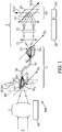
Figure 1 is a general diagram of a spectral imager according to the invention; -
Figure 2 shows optical fibre bending as possibly implemented in accordance with the present invention; and -
Figure 3 illustrates a possible optical fibre arrangement in an entrance optical head used in the spectral imager ofFigure 1 . - For clarity sake, element sizes which appear in these figures do not correspond to actual dimensions or dimension ratios. Also, some of the components used in the invention are represented using symbols. Furthermore, same reference numbers which are indicated in several figures denote identical elements of elements with identical function.
-
Reference number 100 inFigure 1 generally denotes a spectral imager that is in accordance with the present invention. A radiation collecting optics 1 forms an image of a scene S in an intermediate focal plane IFP. In particular, when thespectral imager 100 is intended to be used on-board a satellite for analysing a scene content existing at the surface of the Earth, the radiation collecting optics 1 may be a telescope, such as an anastigmatic three-mirror telescope for example. However, any other telescope type may also be used. Thespectral imager 100 may be combined with a scanning device suitable for varying a line-of-sight of this spectral imager so that the scene image moves according to the arrow SCAN in the intermediate focal plane IFP. Any type of scanning device may be used, including a rotating entrance mirror or a scanning operation that is produced by the orbit and attitude control system of the satellite. - The
spectral imager 100 also comprises aspectrometer 2 which may be of a common type appropriate for the spectral range desired. For example, thespectrometer 2 may comprise in series along a propagation direction of radiation in the spectral imager 100: acollimator 21, a radiation-dispersingelement 22, a re-imager 23 and aphotodetector 24. Although represented each as a single lens for clarity sake of the figure, thecollimator 21 and the re-imager 23 may each be comprised of several optical components, such as mirrors. The radiation-dispersingelement 22 may be a grating of any type, operating through transmission or reflection. Alternatively, it may be a prism. Advantageously, thecollimator 21 is arranged so that the radiation which originates from the intermediate focal plane IFP is collimated at the radiation-dispersingelement 22. The re-imager 23 produces a final image of the scene S in a detection plane DP. Thephotodetector 24 is of matrix type, comprised of an array of photosensitive elements distributed in row and columns in a usual manner. It is arranged so that the array of the photosensitive elements is superposed to the detection plane DP. Due to the radiation-dispersingelement 22, a respective image of the scene S is formed in the detection plane DP for each wavelength value, all images being offset with respect to each other according to the spectral dispersing efficiency of the radiation-dispersingelement 22. SCD indicates the direction of such spectral offset in the detection plane DP, as resulting from the orientation of the radiation-dispersingelement 22. - According to the standard operation of a spectral imager, the scene S is imaged in the detection plane DP along a direction SLD that is perpendicular to the SCD direction. The rows and columns of the
photodetector 24 are parallel and perpendicular to the directions SLD and SCD. Thus, the spectral spreading that is produced along a column parallel to the SCD direction relates to one and same scene point imaged as a pixel, and the scanning of the line-of-sight according to the arrow SCAN makes the image content to move parallel to the SCD direction in the detection plane DP. For such operation, it is necessary that the intermediate image of the scene S which is produced by the radiation collecting optics 1 in the intermediate focal plane IFP is filtered in a manner similar as that produced by a slit-apertured field mask. The slit-shaped aperture of such field mask is to be oriented with the transverse slit direction imaged parallel to the SCD direction by thespectrometer 2, and the longitudinal slit direction imaged parallel to the SLD direction. For this reason, the SCD direction is called slit-across direction and the SLD direction is called slit-along direction. - According to the invention, an optical fibre bundle 3 is inserted in the
spectral imager 100, between the intermediate focal plane IFP and the optical entrance of thespectrometer 2. This optical fibre bundle 3 contains a plurality of independent optical fibres, for example 123 optical fibres, which are gathered in a single pack, preferably with a generally circular bundle cross-sectional area in amain length portion 30 of this bundle. All the optical fibres may have one and same length value in the bundle 3, and extend between an entranceoptical head 31 of the bundle 3 and an outputoptical head 32 of the bundle 3. Whatever the transverse arrangement of the optical fibres in themain length portion 30 of the bundle 3, the optical fibres are re-arranged according to an alignment design in the entranceoptical head 31 and in the outputoptical head 32. Preferably, a peripheral coating that may be provided around each optical fibre in themain length portion 30 of the bundle 3 may be removed at the entrance and outputoptical heads optical head 31 constitute all together an optical slit which is substantially equivalent to a slit-aperture of a field mask. The entranceoptical head 31 is placed in the intermediate focal plane IFP. - Possibly, the optical fibres at the entrance
optical head 31 may be combined with an actual field mask having a slit-aperture that sensibly matches a total area of the entrance ends of the optical fibres. In the figures,reference numbers spectral imager 100 is moved with respect to the scene S. - The output ends of the optical fibres of the bundle 3 within the output
optical head 32 may be aligned within the optical entrance of thespectrometer 2. An alignment direction at this stage in thespectral imager 100 is denoted D2. It may be oriented so that an image of the alignment direction D2 formed by thespectrometer 2 in the detection plane DP is perpendicular to the spectral dispersion direction which is produced by the radiation-dispersingelement 22, i.e. parallel to the SLD direction. In this way, the output ends of the optical fibres form a slit track which serves as a spectrometer entrance slit. It is not necessary that the fibre output ends are arranged exactly as a rectilinear segment in the outputoptical head 32. Advantageously, the slit track formed by the alignment of the fibre output ends in the outputoptical head 32 may be curved, and designed so that the image of the slit track through thespectrometer 2, in the detection plane DP, is rectilinear. In this way, a field distortion of thespectrometer 2 can be compensated for by an appropriate shape of the slit track, i.e. an appropriate curved arrangement of the output ends of theoptical fibres optical head 32. Except a spatial separation thus obtained between the intermediate focal plane IFP and the optical entrance of thespectrometer 2, the optical operation of the spectral imager is unchanged. - At the entrance and output
optical heads optical fibres reference signs support optical head 32. - The spatial separation produced by the optical fibre bundle 3 between the radiation collecting optics 1 and the
spectrometer 2 allows thespectrometer 2 to be decoupled mechanically and/or thermally from the radiation collecting optics 1. For the structural aspects driven by the launch environment constraints they can be considered as separated entities, which separation facilitates the design and testing. The alignment requirements between the two units are easier to meet.. Also, because the bundle 3 has a small cross-sectional area, and because its thermal conduction is low, it is compatible with providing a thermal insulation between the optics 1 and thespectrometer 2. Thus, the optics 1 may be controlled for having a temperature value of about 293 K, and thespectrometer 2 may be controlled for having another temperature value of about 230K. Reference number 10 denotes first temperature control means that may be dedicated to the radiation collecting optics 1, andreference signs 20 and 20' denote other temperature control means that may be dedicated respectively to thespectrometer 2 and thephotodetector 24. - According to the invention, the length of each optical fibre in the bundle 3 is greater than 40 cm, for example equal to about 1 m. Thanks to this minimum length value, the distribution of the radiation intensity across each optical fibre at its output end is almost uniform, whatever any variation that may exist in the radiation intensity across the same optical fibre at its entrance end in the intermediate focal plane IFP. This first effect of the optical fibre bundle 3 may be called near-field homogenization.
- According to an additional invention feature which is optional, the optical fibre bundle 3 is bent within two planes between its entrance
optical head 31 and outputoptical head 32. These planes have thereference numbers Figure 2 . Preferably, theplanes cleats 43 suitable for maintaining the bundle 3 along a curved path on thewall 41 and then on thewall 42. The Man skilled in the art will understand that the exact path shape does not matter really, provided that sufficient curvatures are produced in each plane. For example, the path shape for the bundle 3 may be wavy with three alternated turns on each one of thewalls wall 41, and then one or several second loops parallel to thewall 42. Opposite loop orientations may also be combined on each wall. RC1 and RC2 denote the respective curvature radii parallel to thewalls element 22, is almost uniform whatever any variation that may exist in the radiation intensity across the same optical fibre at its entrance end in the intermediate focal plane IFP. This second effect of the optical fibre bundle 3 when implemented according to the invention may be called far-field homogenization. Thewalls cleats 43 correspond to the bundle shape control means as mentioned in the general part of this description. The bundle shape control means are generally denoted by thereference number 40. Theoptical fibres main length portion 30 of the bundle 3 between the entrance and outputoptical heads cleats 43. Such bundle shape control means 40 produce efficient far-field homogenization, so that the instrument spectral response function of thespectral imager 100 is not affected by radiation intensity variations that may exist across the entrance end of each optical fibre. Put another way, the instrument spectral response function of thespectral imager 100 is not affected by sharp image content variations possibly existing in the intermediate focal plane IFP. -
Figure 3 shows the entrance ends of theoptical fibres optical head 31 for a preferred embodiment of the invention. Eachoptical fibre optical head 31 may be about 420 µm, for allowing a good spatial resolution value for thespectral imager 100 in the detection plane DP. Possibly, such rectangular cross-sectional shape of the optical fibres may be combined with a binning implementation of the photosensitive elements of thephotodetector 24. For obtaining such value for the inter-fibre distance at the entranceoptical head 31, and also at the outputoptical head 32, a potting and/or an external coating of the optical fibres that exists in themain length portion 30 of the bundle 3 between theheads optical head 31 for maintaining fixedly theoptical fibres plate 31S. - Such spectral imager may be useful for many applications, including space applications, for example for missions dedicated to imaging and spectral analysis of a composition existing at the surface of the Earth. For such missions, the
spectral imager 100 may be situated on-board a satellite in orbit around the Earth. Such missions may concern the atmospheric composition as well as landscape composition at the Earth surface.
Claims (14)
- Spectral imager (100) suitable for providing an image of a scene (S) within a detection plane (DP) along a slit-along direction (SLD), and for producing simultaneously a spectral spreading along a slit-across (SCD) direction which is perpendicular to the slit-along direction in the detection plane, said spectral imager comprising:- a radiation collecting optics (1), adapted for producing an intermediate image of the scene (S) within an intermediate focal plane (IFP);- a spectrometer (2), suitable for imaging a content of a slit track in the detection plane (DP) along the slit-along direction (SLD), and for producing the spectral spreading along the slit-across direction (SCD) with radiation that originates from the slit track; and- a photodetector (24) which comprises a two-dimensional array of photosensitive elements, and which is arranged in the detection plane (DP) so that rows of the photosensitive elements are parallel to the slit-along direction (SLD),the spectral imager (100) being characterized in that it also comprises:- an optical fibre bundle (3), which comprises a plurality of optical fibres (301, 302, 303...) extending each from an entrance optical head (31) to an output optical head (32), the optical fibres having respective entrance ends aligned within the entrance optical head, and respective output ends aligned within the output optical head,the optical fibre bundle (3) being arranged so that the entrance optical head (31) is located in the intermediate focal plane (IFP), and the output optical head (32) forms the slit track, and
a length of the optical fibres (301, 302, 303...) in the optical fibre bundle (3) between the entrance optical head (31) and the output optical head (32) being comprised between 40 cm and 2 m. - Spectral imager (100) according to Claim 1, further comprising:- bundle shape control means (40), that are suitable for fixedly determining a shape of the optical fibres (301, 302, 303...) between the entrance optical head (31) and the optical output head (32),the bundle shape control means (40) being adapted for maintaining curvatures of each one of the optical fibres (301, 302, 303...) within two planes (41, 42) that are angularly separated, with curvature radii comprised between 0.5 cm and 20 cm for each plane.
- Spectral imager (100) according to Claim 2, wherein the bundle shape control means (40) are adapted for maintaining each one of the optical fibres (301, 302, 303...) along a wavy path in each of the planes (41, 42), with two or three turns in each plane, two successive turns in each plane being separated by a change in a curvature direction of said optical fibre.
- Spectral imager (100) according to any one of the preceding claims, wherein the optical fibres (301, 302, 303...) are gathered in the optical fibre bundle (3) with a circular cross-sectional bundle shape at at least one location between the entrance optical head (31) and the output optical head (32).
- Spectral imager (100) according to any one of the preceding claims, wherein each optical fibre (301, 302, 303...) has an individual core cross-section that is square or rectangular.
- Spectral imager (100) according to any one of the preceding claims, wherein the optical fibres (301, 302, 303...) are aligned in the entrance optical head (31) according to a rectilinear segment, and are aligned in the output optical head (32) according to a curved track for compensating for a field distortion of the spectrometer (2), so that an image of the rectilinear segment at the entrance optical head is rectilinear in the detection plane (DP).
- Spectral imager (100) according to any one of the preceding claims, wherein the optical fibre bundle (3) comprises more than 50 optical fibres (301, 302, 303...), preferably between 63 and 257 optical fibres.
- Spectral imager (100) according to any one of the preceding claims, further comprising temperature control means (10, 20, 20') arranged so that, during an operation of the spectral imager, a temperature value of the entrance optical head (31) of the optical fibre bundle (3) is higher than 270 K, and another temperature value of the output optical head (32) of said optical fibre bundle is lower than 260 K.
- Spectral imager (100) according to any one of the preceding claims, wherein the optical fibres (301, 302, 303...) are fixedly supported by a first rigid element (31S) at the entrance optical head (31), and fixedly supported by a second rigid element (32S) at the output optical head (32), said first and second rigid elements being separated and distant from each other.
- Spectral imager (100) according to any one of the preceding claims, wherein the optical fibres (301, 302, 303...) are of multimode type for radiation that is processed and detected by said spectral imager.
- Spectral imager (100) according to any one of the preceding claims, wherein each optical fibre (301, 302, 303...) is comprised of a core (CR) and a cladding (CL), and is surrounded with a coating which is external to the cladding in at least an intermediate length portion (30) of the optical fibre bundle (3) between the entrance optical head (31) and the output optical head (32), and an inter-core distance value between neighbouring ones of the optical fibres within the entrance and output optical heads is smaller than another inter-core distance value between neighbouring ones of the optical fibres as existing in the intermediate length portion of the optical fibre bundle.
- Process for optically analysing a portion of the Earth, using a spectral imager (100) that is in accordance with any one of the preceding claims, said spectral imager being on-board a satellite.
- Process according to claim 12, wherein a spectral operation range of the spectral imager (100) is suitable for analysing a CO2-content existing at a location on the Earth.
- Process according to claim 12 or 13, implemented with moving a line-of-sight of the spectral imager (100) towards the Earth portion so that an image movement on the photodetector (24) has a component parallel to the slit-across direction (SCD), and a plurality of images is captured while the line-of-sight is moved.
Priority Applications (1)
| Application Number | Priority Date | Filing Date | Title |
|---|---|---|---|
| EP20305786.4A EP3936841B1 (en) | 2020-07-08 | 2020-07-08 | Spectral imager and process using the same |
Applications Claiming Priority (1)
| Application Number | Priority Date | Filing Date | Title |
|---|---|---|---|
| EP20305786.4A EP3936841B1 (en) | 2020-07-08 | 2020-07-08 | Spectral imager and process using the same |
Publications (3)
| Publication Number | Publication Date |
|---|---|
| EP3936841A1 true EP3936841A1 (en) | 2022-01-12 |
| EP3936841B1 EP3936841B1 (en) | 2024-06-05 |
| EP3936841C0 EP3936841C0 (en) | 2024-06-05 |
Family
ID=72615765
Family Applications (1)
| Application Number | Title | Priority Date | Filing Date |
|---|---|---|---|
| EP20305786.4A Active EP3936841B1 (en) | 2020-07-08 | 2020-07-08 | Spectral imager and process using the same |
Country Status (1)
| Country | Link |
|---|---|
| EP (1) | EP3936841B1 (en) |
Cited By (1)
| Publication number | Priority date | Publication date | Assignee | Title |
|---|---|---|---|---|
| EP4560276A1 (en) | 2023-11-23 | 2025-05-28 | Thales | Optical component for an observation or measuring instrument for homogenising non-uniformities of a spatial sample for multi-spectral observation |
Citations (4)
| Publication number | Priority date | Publication date | Assignee | Title |
|---|---|---|---|---|
| US5768040A (en) * | 1995-10-06 | 1998-06-16 | Orbital Sciences Corporation | Wide field-of-view imaging spectrometer |
| US20040178329A1 (en) * | 2003-03-13 | 2004-09-16 | The Boeing Company | Remote sensing apparatus and method |
| CN102435311B (en) * | 2011-09-07 | 2014-05-07 | 杭州远方光电信息股份有限公司 | Optical fiber bundle spectrometer |
| EP3605045A1 (en) | 2018-07-30 | 2020-02-05 | Nederlandse Organisatie voor toegepast- natuurwetenschappelijk onderzoek TNO | Slit homogenizer for spectral imaging |
-
2020
- 2020-07-08 EP EP20305786.4A patent/EP3936841B1/en active Active
Patent Citations (4)
| Publication number | Priority date | Publication date | Assignee | Title |
|---|---|---|---|---|
| US5768040A (en) * | 1995-10-06 | 1998-06-16 | Orbital Sciences Corporation | Wide field-of-view imaging spectrometer |
| US20040178329A1 (en) * | 2003-03-13 | 2004-09-16 | The Boeing Company | Remote sensing apparatus and method |
| CN102435311B (en) * | 2011-09-07 | 2014-05-07 | 杭州远方光电信息股份有限公司 | Optical fiber bundle spectrometer |
| EP3605045A1 (en) | 2018-07-30 | 2020-02-05 | Nederlandse Organisatie voor toegepast- natuurwetenschappelijk onderzoek TNO | Slit homogenizer for spectral imaging |
Non-Patent Citations (2)
| Title |
|---|
| UTO KUNIAKI ET AL: "Development of a Low-Cost Hyperspectral Whiskbroom Imager Using an Optical Fiber Bundle, a Swing Mirror, and Compact Spectrometers", IEEE JOURNAL OF SELECTED TOPICS IN APPLIED EARTH OBSERVATIONS AND REMOTE SENSING, IEEE, USA, vol. 9, no. 9, 2 September 2016 (2016-09-02), pages 3909 - 3925, XP011624723, ISSN: 1939-1404, [retrieved on 20161003], DOI: 10.1109/JSTARS.2016.2592987 * |
| WEI LIDONG ET AL: "Study of wide-field imaging spectrometer based on Fery prism with optical fiber array", PROCEEDINGS OF SPIE; [PROCEEDINGS OF SPIE; ISSN 0277-786X; VOL. 8615], SPIE, 1000 20TH ST. BELLINGHAM WA 98225-6705 USA, vol. 10785, 25 September 2018 (2018-09-25), pages 107851P - 107851P, XP060111798, ISBN: 978-1-5106-2099-5, DOI: 10.1117/12.2325595 * |
Cited By (2)
| Publication number | Priority date | Publication date | Assignee | Title |
|---|---|---|---|---|
| EP4560276A1 (en) | 2023-11-23 | 2025-05-28 | Thales | Optical component for an observation or measuring instrument for homogenising non-uniformities of a spatial sample for multi-spectral observation |
| FR3155913A1 (en) | 2023-11-23 | 2025-05-30 | Thales | Optical component for an observation or measurement instrument for homogenizing non-uniformities of a spatial sample for multi-spectral observation |
Also Published As
| Publication number | Publication date |
|---|---|
| EP3936841B1 (en) | 2024-06-05 |
| EP3936841C0 (en) | 2024-06-05 |
Similar Documents
| Publication | Publication Date | Title |
|---|---|---|
| Sierk et al. | The Copernicus CO2M mission for monitoring anthropogenic carbon dioxide emissions from space | |
| US7808635B2 (en) | Wide swath imaging spectrometer utilizing a multi-modular design | |
| Nieke et al. | Imaging spaceborne and airborne sensor systems in the beginning of the next century | |
| US5768040A (en) | Wide field-of-view imaging spectrometer | |
| CN111174914A (en) | A video hyperspectral imager based on array slit scanning | |
| US8203710B1 (en) | Compact wide field fast hyperspectral imager | |
| EP3936841B1 (en) | Spectral imager and process using the same | |
| Lites et al. | The solar-B spectro-polarimeter | |
| EP3415882A1 (en) | Imaging spectrophotometer and satellite comprising the same | |
| US6185037B1 (en) | Optical reconnaissance system | |
| US8415599B2 (en) | Device for measuring the defects of an imaging instrument with two opto-electronic sensors | |
| US20240264460A1 (en) | Serpentine Integrated Grating and Associated Devices | |
| CN109844471B (en) | Spectrophotometric device with multiple spectral measurement bands | |
| Blechinger et al. | High-resolution imaging spectrometer (HRIS): Optics, focal plane, and calibration | |
| Filacchione et al. | The Integral-Field Imager and Spectrometer for planetary exploration (ƒISPEx) | |
| KR101561714B1 (en) | Compact stereoscopic imaging device | |
| RU2529052C2 (en) | Space telescope | |
| US11480806B2 (en) | Cassegrain telescope with a segmented focal plane | |
| CN119958695B (en) | Airborne high-frequency linear array sweeping imaging spectroscopic system based on optical waveguide devices | |
| JP2005062202A (en) | Spectrometer | |
| Lobb | Wide-angle optical systems with moderate spectral resolution, for monitoring the oceans from low Earth orbit | |
| Walker et al. | Echelle spectrographs for 8-m class telescopes | |
| Swanson et al. | Anamorphic imaging spectrometer | |
| CN120831173A (en) | Dispersion polarization spectrum imaging system and method based on Savart polarizer channel | |
| Delabre et al. | CODEX optics |
Legal Events
| Date | Code | Title | Description |
|---|---|---|---|
| PUAI | Public reference made under article 153(3) epc to a published international application that has entered the european phase |
Free format text: ORIGINAL CODE: 0009012 |
|
| STAA | Information on the status of an ep patent application or granted ep patent |
Free format text: STATUS: THE APPLICATION HAS BEEN PUBLISHED |
|
| AK | Designated contracting states |
Kind code of ref document: A1 Designated state(s): AL AT BE BG CH CY CZ DE DK EE ES FI FR GB GR HR HU IE IS IT LI LT LU LV MC MK MT NL NO PL PT RO RS SE SI SK SM TR |
|
| B565 | Issuance of search results under rule 164(2) epc |
Effective date: 20210113 |
|
| STAA | Information on the status of an ep patent application or granted ep patent |
Free format text: STATUS: REQUEST FOR EXAMINATION WAS MADE |
|
| 17P | Request for examination filed |
Effective date: 20220706 |
|
| RBV | Designated contracting states (corrected) |
Designated state(s): AL AT BE BG CH CY CZ DE DK EE ES FI FR GB GR HR HU IE IS IT LI LT LU LV MC MK MT NL NO PL PT RO RS SE SI SK SM TR |
|
| GRAP | Despatch of communication of intention to grant a patent |
Free format text: ORIGINAL CODE: EPIDOSNIGR1 |
|
| STAA | Information on the status of an ep patent application or granted ep patent |
Free format text: STATUS: GRANT OF PATENT IS INTENDED |
|
| RIC1 | Information provided on ipc code assigned before grant |
Ipc: G01J 3/04 20060101ALN20240222BHEP Ipc: G01J 3/18 20060101ALI20240222BHEP Ipc: G01J 3/14 20060101ALI20240222BHEP Ipc: H04N 1/195 20060101ALI20240222BHEP Ipc: G01J 3/02 20060101ALI20240222BHEP Ipc: G01J 3/28 20060101AFI20240222BHEP |
|
| INTG | Intention to grant announced |
Effective date: 20240311 |
|
| GRAS | Grant fee paid |
Free format text: ORIGINAL CODE: EPIDOSNIGR3 |
|
| GRAA | (expected) grant |
Free format text: ORIGINAL CODE: 0009210 |
|
| STAA | Information on the status of an ep patent application or granted ep patent |
Free format text: STATUS: THE PATENT HAS BEEN GRANTED |
|
| AK | Designated contracting states |
Kind code of ref document: B1 Designated state(s): AL AT BE BG CH CY CZ DE DK EE ES FI FR GB GR HR HU IE IS IT LI LT LU LV MC MK MT NL NO PL PT RO RS SE SI SK SM TR |
|
| REG | Reference to a national code |
Ref country code: CH Ref legal event code: EP |
|
| REG | Reference to a national code |
Ref country code: DE Ref legal event code: R096 Ref document number: 602020031924 Country of ref document: DE |
|
| REG | Reference to a national code |
Ref country code: IE Ref legal event code: FG4D |
|
| U01 | Request for unitary effect filed |
Effective date: 20240605 |
|
| U07 | Unitary effect registered |
Designated state(s): AT BE BG DE DK EE FI FR IT LT LU LV MT NL PT SE SI Effective date: 20240613 |
|
| U1N | Appointed representative for the unitary patent procedure changed after the registration of the unitary effect |
Representative=s name: PLASSERAUD IP; FR |
|
| U20 | Renewal fee for the european patent with unitary effect paid |
Year of fee payment: 5 Effective date: 20240827 |
|
| PG25 | Lapsed in a contracting state [announced via postgrant information from national office to epo] |
Ref country code: HR Free format text: LAPSE BECAUSE OF FAILURE TO SUBMIT A TRANSLATION OF THE DESCRIPTION OR TO PAY THE FEE WITHIN THE PRESCRIBED TIME-LIMIT Effective date: 20240605 |
|
| PG25 | Lapsed in a contracting state [announced via postgrant information from national office to epo] |
Ref country code: GR Free format text: LAPSE BECAUSE OF FAILURE TO SUBMIT A TRANSLATION OF THE DESCRIPTION OR TO PAY THE FEE WITHIN THE PRESCRIBED TIME-LIMIT Effective date: 20240906 |
|
| PG25 | Lapsed in a contracting state [announced via postgrant information from national office to epo] |
Ref country code: ES Free format text: LAPSE BECAUSE OF FAILURE TO SUBMIT A TRANSLATION OF THE DESCRIPTION OR TO PAY THE FEE WITHIN THE PRESCRIBED TIME-LIMIT Effective date: 20240605 |
|
| PG25 | Lapsed in a contracting state [announced via postgrant information from national office to epo] |
Ref country code: NO Free format text: LAPSE BECAUSE OF FAILURE TO SUBMIT A TRANSLATION OF THE DESCRIPTION OR TO PAY THE FEE WITHIN THE PRESCRIBED TIME-LIMIT Effective date: 20240905 Ref country code: HR Free format text: LAPSE BECAUSE OF FAILURE TO SUBMIT A TRANSLATION OF THE DESCRIPTION OR TO PAY THE FEE WITHIN THE PRESCRIBED TIME-LIMIT Effective date: 20240605 Ref country code: GR Free format text: LAPSE BECAUSE OF FAILURE TO SUBMIT A TRANSLATION OF THE DESCRIPTION OR TO PAY THE FEE WITHIN THE PRESCRIBED TIME-LIMIT Effective date: 20240906 Ref country code: ES Free format text: LAPSE BECAUSE OF FAILURE TO SUBMIT A TRANSLATION OF THE DESCRIPTION OR TO PAY THE FEE WITHIN THE PRESCRIBED TIME-LIMIT Effective date: 20240605 Ref country code: RS Free format text: LAPSE BECAUSE OF FAILURE TO SUBMIT A TRANSLATION OF THE DESCRIPTION OR TO PAY THE FEE WITHIN THE PRESCRIBED TIME-LIMIT Effective date: 20240905 |
|
| PG25 | Lapsed in a contracting state [announced via postgrant information from national office to epo] |
Ref country code: PL Free format text: LAPSE BECAUSE OF FAILURE TO SUBMIT A TRANSLATION OF THE DESCRIPTION OR TO PAY THE FEE WITHIN THE PRESCRIBED TIME-LIMIT Effective date: 20240605 |
|
| PG25 | Lapsed in a contracting state [announced via postgrant information from national office to epo] |
Ref country code: IS Free format text: LAPSE BECAUSE OF FAILURE TO SUBMIT A TRANSLATION OF THE DESCRIPTION OR TO PAY THE FEE WITHIN THE PRESCRIBED TIME-LIMIT Effective date: 20241005 |
|
| PG25 | Lapsed in a contracting state [announced via postgrant information from national office to epo] |
Ref country code: CZ Free format text: LAPSE BECAUSE OF FAILURE TO SUBMIT A TRANSLATION OF THE DESCRIPTION OR TO PAY THE FEE WITHIN THE PRESCRIBED TIME-LIMIT Effective date: 20240605 |
|
| PG25 | Lapsed in a contracting state [announced via postgrant information from national office to epo] |
Ref country code: RO Free format text: LAPSE BECAUSE OF FAILURE TO SUBMIT A TRANSLATION OF THE DESCRIPTION OR TO PAY THE FEE WITHIN THE PRESCRIBED TIME-LIMIT Effective date: 20240605 Ref country code: SK Free format text: LAPSE BECAUSE OF FAILURE TO SUBMIT A TRANSLATION OF THE DESCRIPTION OR TO PAY THE FEE WITHIN THE PRESCRIBED TIME-LIMIT Effective date: 20240605 |
|
| PG25 | Lapsed in a contracting state [announced via postgrant information from national office to epo] |
Ref country code: SM Free format text: LAPSE BECAUSE OF FAILURE TO SUBMIT A TRANSLATION OF THE DESCRIPTION OR TO PAY THE FEE WITHIN THE PRESCRIBED TIME-LIMIT Effective date: 20240605 |
|
| PG25 | Lapsed in a contracting state [announced via postgrant information from national office to epo] |
Ref country code: SM Free format text: LAPSE BECAUSE OF FAILURE TO SUBMIT A TRANSLATION OF THE DESCRIPTION OR TO PAY THE FEE WITHIN THE PRESCRIBED TIME-LIMIT Effective date: 20240605 Ref country code: SK Free format text: LAPSE BECAUSE OF FAILURE TO SUBMIT A TRANSLATION OF THE DESCRIPTION OR TO PAY THE FEE WITHIN THE PRESCRIBED TIME-LIMIT Effective date: 20240605 Ref country code: RO Free format text: LAPSE BECAUSE OF FAILURE TO SUBMIT A TRANSLATION OF THE DESCRIPTION OR TO PAY THE FEE WITHIN THE PRESCRIBED TIME-LIMIT Effective date: 20240605 Ref country code: PL Free format text: LAPSE BECAUSE OF FAILURE TO SUBMIT A TRANSLATION OF THE DESCRIPTION OR TO PAY THE FEE WITHIN THE PRESCRIBED TIME-LIMIT Effective date: 20240605 Ref country code: IS Free format text: LAPSE BECAUSE OF FAILURE TO SUBMIT A TRANSLATION OF THE DESCRIPTION OR TO PAY THE FEE WITHIN THE PRESCRIBED TIME-LIMIT Effective date: 20241005 Ref country code: CZ Free format text: LAPSE BECAUSE OF FAILURE TO SUBMIT A TRANSLATION OF THE DESCRIPTION OR TO PAY THE FEE WITHIN THE PRESCRIBED TIME-LIMIT Effective date: 20240605 |
|
| REG | Reference to a national code |
Ref country code: CH Ref legal event code: PL |
|
| PG25 | Lapsed in a contracting state [announced via postgrant information from national office to epo] |
Ref country code: MC Free format text: LAPSE BECAUSE OF FAILURE TO SUBMIT A TRANSLATION OF THE DESCRIPTION OR TO PAY THE FEE WITHIN THE PRESCRIBED TIME-LIMIT Effective date: 20240605 |
|
| PG25 | Lapsed in a contracting state [announced via postgrant information from national office to epo] |
Ref country code: MC Free format text: LAPSE BECAUSE OF FAILURE TO SUBMIT A TRANSLATION OF THE DESCRIPTION OR TO PAY THE FEE WITHIN THE PRESCRIBED TIME-LIMIT Effective date: 20240605 |
|
| PLBE | No opposition filed within time limit |
Free format text: ORIGINAL CODE: 0009261 |
|
| STAA | Information on the status of an ep patent application or granted ep patent |
Free format text: STATUS: NO OPPOSITION FILED WITHIN TIME LIMIT |
|
| PG25 | Lapsed in a contracting state [announced via postgrant information from national office to epo] |
Ref country code: CH Free format text: LAPSE BECAUSE OF NON-PAYMENT OF DUE FEES Effective date: 20240731 |
|
| 26N | No opposition filed |
Effective date: 20250306 |
|
| PG25 | Lapsed in a contracting state [announced via postgrant information from national office to epo] |
Ref country code: IE Free format text: LAPSE BECAUSE OF NON-PAYMENT OF DUE FEES Effective date: 20240708 |
|
| U20 | Renewal fee for the european patent with unitary effect paid |
Year of fee payment: 6 Effective date: 20250728 |
|
| PGFP | Annual fee paid to national office [announced via postgrant information from national office to epo] |
Ref country code: GB Payment date: 20250722 Year of fee payment: 6 |
|
| PG25 | Lapsed in a contracting state [announced via postgrant information from national office to epo] |
Ref country code: CY Free format text: LAPSE BECAUSE OF FAILURE TO SUBMIT A TRANSLATION OF THE DESCRIPTION OR TO PAY THE FEE WITHIN THE PRESCRIBED TIME-LIMIT; INVALID AB INITIO Effective date: 20200708 |
|
| PG25 | Lapsed in a contracting state [announced via postgrant information from national office to epo] |
Ref country code: HU Free format text: LAPSE BECAUSE OF FAILURE TO SUBMIT A TRANSLATION OF THE DESCRIPTION OR TO PAY THE FEE WITHIN THE PRESCRIBED TIME-LIMIT; INVALID AB INITIO Effective date: 20200708 |
|
| PG25 | Lapsed in a contracting state [announced via postgrant information from national office to epo] |
Ref country code: TR Free format text: LAPSE BECAUSE OF FAILURE TO SUBMIT A TRANSLATION OF THE DESCRIPTION OR TO PAY THE FEE WITHIN THE PRESCRIBED TIME-LIMIT Effective date: 20240605 |