EP3936831A1 - Calibration bracket - Google Patents
Calibration bracket Download PDFInfo
- Publication number
- EP3936831A1 EP3936831A1 EP20772809.8A EP20772809A EP3936831A1 EP 3936831 A1 EP3936831 A1 EP 3936831A1 EP 20772809 A EP20772809 A EP 20772809A EP 3936831 A1 EP3936831 A1 EP 3936831A1
- Authority
- EP
- European Patent Office
- Prior art keywords
- support rod
- calibration
- connecting shaft
- base
- angle adjustment
- Prior art date
- Legal status (The legal status is an assumption and is not a legal conclusion. Google has not performed a legal analysis and makes no representation as to the accuracy of the status listed.)
- Granted
Links
Images




Classifications
-
- G—PHYSICS
- G01—MEASURING; TESTING
- G01D—MEASURING NOT SPECIALLY ADAPTED FOR A SPECIFIC VARIABLE; ARRANGEMENTS FOR MEASURING TWO OR MORE VARIABLES NOT COVERED IN A SINGLE OTHER SUBCLASS; TARIFF METERING APPARATUS; MEASURING OR TESTING NOT OTHERWISE PROVIDED FOR
- G01D18/00—Testing or calibrating apparatus or arrangements provided for in groups G01D1/00 - G01D15/00
-
- F—MECHANICAL ENGINEERING; LIGHTING; HEATING; WEAPONS; BLASTING
- F16—ENGINEERING ELEMENTS AND UNITS; GENERAL MEASURES FOR PRODUCING AND MAINTAINING EFFECTIVE FUNCTIONING OF MACHINES OR INSTALLATIONS; THERMAL INSULATION IN GENERAL
- F16M—FRAMES, CASINGS OR BEDS OF ENGINES, MACHINES OR APPARATUS, NOT SPECIFIC TO ENGINES, MACHINES OR APPARATUS PROVIDED FOR ELSEWHERE; STANDS; SUPPORTS
- F16M13/00—Other supports for positioning apparatus or articles; Means for steadying hand-held apparatus or articles
- F16M13/02—Other supports for positioning apparatus or articles; Means for steadying hand-held apparatus or articles for supporting on, or attaching to, an object, e.g. tree, gate, window-frame, cycle
- F16M13/022—Other supports for positioning apparatus or articles; Means for steadying hand-held apparatus or articles for supporting on, or attaching to, an object, e.g. tree, gate, window-frame, cycle repositionable
-
- F—MECHANICAL ENGINEERING; LIGHTING; HEATING; WEAPONS; BLASTING
- F16—ENGINEERING ELEMENTS AND UNITS; GENERAL MEASURES FOR PRODUCING AND MAINTAINING EFFECTIVE FUNCTIONING OF MACHINES OR INSTALLATIONS; THERMAL INSULATION IN GENERAL
- F16M—FRAMES, CASINGS OR BEDS OF ENGINES, MACHINES OR APPARATUS, NOT SPECIFIC TO ENGINES, MACHINES OR APPARATUS PROVIDED FOR ELSEWHERE; STANDS; SUPPORTS
- F16M11/00—Stands or trestles as supports for apparatus or articles placed thereon ; Stands for scientific apparatus such as gravitational force meters
- F16M11/02—Heads
- F16M11/04—Means for attachment of apparatus; Means allowing adjustment of the apparatus relatively to the stand
- F16M11/06—Means for attachment of apparatus; Means allowing adjustment of the apparatus relatively to the stand allowing pivoting
- F16M11/12—Means for attachment of apparatus; Means allowing adjustment of the apparatus relatively to the stand allowing pivoting in more than one direction
- F16M11/14—Means for attachment of apparatus; Means allowing adjustment of the apparatus relatively to the stand allowing pivoting in more than one direction with ball-joint
-
- F—MECHANICAL ENGINEERING; LIGHTING; HEATING; WEAPONS; BLASTING
- F16—ENGINEERING ELEMENTS AND UNITS; GENERAL MEASURES FOR PRODUCING AND MAINTAINING EFFECTIVE FUNCTIONING OF MACHINES OR INSTALLATIONS; THERMAL INSULATION IN GENERAL
- F16M—FRAMES, CASINGS OR BEDS OF ENGINES, MACHINES OR APPARATUS, NOT SPECIFIC TO ENGINES, MACHINES OR APPARATUS PROVIDED FOR ELSEWHERE; STANDS; SUPPORTS
- F16M11/00—Stands or trestles as supports for apparatus or articles placed thereon ; Stands for scientific apparatus such as gravitational force meters
- F16M11/02—Heads
- F16M11/18—Heads with mechanism for moving the apparatus relatively to the stand
-
- F—MECHANICAL ENGINEERING; LIGHTING; HEATING; WEAPONS; BLASTING
- F16—ENGINEERING ELEMENTS AND UNITS; GENERAL MEASURES FOR PRODUCING AND MAINTAINING EFFECTIVE FUNCTIONING OF MACHINES OR INSTALLATIONS; THERMAL INSULATION IN GENERAL
- F16M—FRAMES, CASINGS OR BEDS OF ENGINES, MACHINES OR APPARATUS, NOT SPECIFIC TO ENGINES, MACHINES OR APPARATUS PROVIDED FOR ELSEWHERE; STANDS; SUPPORTS
- F16M11/00—Stands or trestles as supports for apparatus or articles placed thereon ; Stands for scientific apparatus such as gravitational force meters
- F16M11/20—Undercarriages with or without wheels
- F16M11/2007—Undercarriages with or without wheels comprising means allowing pivoting adjustment
- F16M11/2021—Undercarriages with or without wheels comprising means allowing pivoting adjustment around a horizontal axis
-
- F—MECHANICAL ENGINEERING; LIGHTING; HEATING; WEAPONS; BLASTING
- F16—ENGINEERING ELEMENTS AND UNITS; GENERAL MEASURES FOR PRODUCING AND MAINTAINING EFFECTIVE FUNCTIONING OF MACHINES OR INSTALLATIONS; THERMAL INSULATION IN GENERAL
- F16M—FRAMES, CASINGS OR BEDS OF ENGINES, MACHINES OR APPARATUS, NOT SPECIFIC TO ENGINES, MACHINES OR APPARATUS PROVIDED FOR ELSEWHERE; STANDS; SUPPORTS
- F16M11/00—Stands or trestles as supports for apparatus or articles placed thereon ; Stands for scientific apparatus such as gravitational force meters
- F16M11/20—Undercarriages with or without wheels
- F16M11/24—Undercarriages with or without wheels changeable in height or length of legs, also for transport only, e.g. by means of tubes screwed into each other
-
- G—PHYSICS
- G01—MEASURING; TESTING
- G01D—MEASURING NOT SPECIALLY ADAPTED FOR A SPECIFIC VARIABLE; ARRANGEMENTS FOR MEASURING TWO OR MORE VARIABLES NOT COVERED IN A SINGLE OTHER SUBCLASS; TARIFF METERING APPARATUS; MEASURING OR TESTING NOT OTHERWISE PROVIDED FOR
- G01D11/00—Component parts of measuring arrangements not specially adapted for a specific variable
- G01D11/30—Supports specially adapted for an instrument; Supports specially adapted for a set of instruments
-
- G—PHYSICS
- G01—MEASURING; TESTING
- G01S—RADIO DIRECTION-FINDING; RADIO NAVIGATION; DETERMINING DISTANCE OR VELOCITY BY USE OF RADIO WAVES; LOCATING OR PRESENCE-DETECTING BY USE OF THE REFLECTION OR RERADIATION OF RADIO WAVES; ANALOGOUS ARRANGEMENTS USING OTHER WAVES
- G01S17/00—Systems using the reflection or reradiation of electromagnetic waves other than radio waves, e.g. lidar systems
- G01S17/88—Lidar systems specially adapted for specific applications
- G01S17/93—Lidar systems specially adapted for specific applications for anti-collision purposes
- G01S17/931—Lidar systems specially adapted for specific applications for anti-collision purposes of land vehicles
-
- G—PHYSICS
- G01—MEASURING; TESTING
- G01S—RADIO DIRECTION-FINDING; RADIO NAVIGATION; DETERMINING DISTANCE OR VELOCITY BY USE OF RADIO WAVES; LOCATING OR PRESENCE-DETECTING BY USE OF THE REFLECTION OR RERADIATION OF RADIO WAVES; ANALOGOUS ARRANGEMENTS USING OTHER WAVES
- G01S7/00—Details of systems according to groups G01S13/00, G01S15/00, G01S17/00
- G01S7/48—Details of systems according to groups G01S13/00, G01S15/00, G01S17/00 of systems according to group G01S17/00
- G01S7/497—Means for monitoring or calibrating
- G01S7/4972—Alignment of sensor
-
- G—PHYSICS
- G01—MEASURING; TESTING
- G01S—RADIO DIRECTION-FINDING; RADIO NAVIGATION; DETERMINING DISTANCE OR VELOCITY BY USE OF RADIO WAVES; LOCATING OR PRESENCE-DETECTING BY USE OF THE REFLECTION OR RERADIATION OF RADIO WAVES; ANALOGOUS ARRANGEMENTS USING OTHER WAVES
- G01S7/00—Details of systems according to groups G01S13/00, G01S15/00, G01S17/00
- G01S7/02—Details of systems according to groups G01S13/00, G01S15/00, G01S17/00 of systems according to group G01S13/00
- G01S7/40—Means for monitoring or calibrating
- G01S7/4052—Means for monitoring or calibrating by simulation of echoes
- G01S7/4082—Means for monitoring or calibrating by simulation of echoes using externally generated reference signals, e.g. via remote reflector or transponder
- G01S7/4086—Means for monitoring or calibrating by simulation of echoes using externally generated reference signals, e.g. via remote reflector or transponder in a calibrating environment, e.g. anechoic chamber
Definitions
- the present application relates to the technical field of vehicle maintenance and repair as well as device calibration, and in particular, to a calibration bracket.
- An advanced driver assistant system (ADAS for short) is an active security technology of collecting environmental data inside and outside a vehicle at the prime time by using various sensors mounted to the vehicle to perform technical processing such as identification, detection, and tracking of static and dynamic objects, enabling a driver to perceive a potential danger as quickly as possible, thereby attracting attention and improving security.
- the ADAS is mainly used to detect light, heat, pressure, or other variables for monitoring a state of the vehicle by using a vehicle-mounted camera, radar, a laser, an ultrasonic wave and the like.
- vibration, collision, environmental temperature and humidity, and the like change physical mounting states of the foregoing sensors, and therefore irregular correction or calibration is required.
- embodiments of the present invention provide a calibration bracket capable of flexibly adjusting angles.
- the embodiments of the present invention adopt the following technical solution to resolve the technical problem.
- a calibration bracket including:
- the base includes a limiting portion configured to limit a range of movement of the angle adjustment structure.
- the base includes a positioning portion configured to fix the angle adjustment structure to a specific position within the range of movement or fix the angle adjustment structure to any position within the range of movement.
- the limiting portion includes a top face and an abutting face; and in a first position, the main rod abuts against the top face, and in a second position, the angle adjustment structure abuts against the abutting face, the range of movement of the angle adjustment structure being between the first position and the second position.
- the top face is substantially parallel to the ground plane on which the base is located.
- an angle of the support rod relative to the ground plane on which the base is located is greater than 90 degrees.
- the base includes two hinge portions;
- the hanger includes a connecting shaft and a movable shaft
- a receiving cavity is provided on the connecting shaft, the receiving cavity being configured to receive a universal ball, the universal ball being rotatable in any direction in the receiving cavity; and the movable shaft is connected to the universal ball and is rotatable about a center of the universal ball relative to the connecting shaft.
- the hanger further includes a locking structure; and the locking structure is configured to fix a position of the movable shaft relative to the connecting shaft.
- the locking structure includes a locking screw, a screw hole mated with the locking screw being provided on the connecting shaft, the locking screw passing through the screw hole to abut against the universal ball to fix the position of the movable shaft relative to the connecting shaft.
- a receiving groove is provided on the connecting shaft, the receiving groove being in communication with the receiving cavity; and when an axis of the connecting shaft is perpendicular to an axis of the movable shaft, the movable shaft is received in the receiving groove.
- a spirit level is disposed on the hanger, the spirit level being configured to keep the axis of the movable shaft horizontal.
- the support rod is inserted into the connecting shaft.
- the connecting shaft is movable in a length direction of the support rod.
- the support rod in the embodiment of the present invention is movably connected to the base, and the support rod is rotatable relative to the base.
- a range of angular rotation of the support rod is controlled by limiting positions in which the main rod of the support rod and the angle adjustment structure abut against the base, so that the support rod can flexibly adjust the angle within the range of angular rotation.
- the hanger is mounted to the support rod and is configured to hang a calibration element on the support rod, so that a calibration angle of the calibration element can be flexibly adjusted.
- a calibration bracket 100 in the embodiment of the present application is configured to calibrate an advanced driver assistant system of a vehicle. Before calibration, the calibration bracket 100 is first positioned, so that the calibration bracket is in a preset position relative to the vehicle. Since a calibration element 40 is hung on the calibration bracket 100, the calibration element 40 may be caused to be aligned to a to-be-calibrated device of the vehicle, such as a camera, a radar, and the like.
- the calibration element may be a multi-line laser emitter 200, a calibration target, a radar reflection or absorption device, or the like.
- the calibration bracket 100 provided in one of the embodiments of the present invention includes a base 10, a support rod 20, a hanger 30 and a calibration element 40.
- the base 10 is hinged to the support rod 20, the support rod 20 is rotatable about the hinge shaft relative to the base 10, the hanger 30 is connected to the support rod 20, and the calibration element 40 is hung on the hanger 30.
- the hinged connection of the base 10 and the support rod 20 means that the base 10 and the support rod 20 are separable or inseparable, and the support rod 20 is movable relative to the base 10.
- the support rod 20 is rotatable about a hinge shaft relative to the base 10.
- the hinge shaft may be disposed as a shaft in a specific direction according to a mechanism between the base 10 and the support rod 20 or disposed as a universal shaft.
- the base 10 includes a limiting portion 11 and a hinge portion 12.
- the limiting portion 11 includes a bottom plate 110, an arc-shaped portion and a column.
- the bottom plate 110 is used to be placed on the ground plane.
- An arc-shaped portion bulges upward on the bottom plate 110, and the arc-shaped portion has an upper surface 112 and an arc face 114.
- the upper surface 112 faces away from the bottom plate 110, and the arc face 114 is connected between the upper surface 112 and the bottom plate 110.
- the column protrudes from the upper surface 112 of the arc-shaped portion toward a direction away from the bottom plate 110.
- the column has a top face 116 and an abutting face 118.
- the top face 116 faces away from the arc-shaped portion 112, and the abutting face 118 is connected between the top face 116 and the arc-shaped portion 112.
- the top face 116 is substantially parallel to the ground plane on which the base 10 is located.
- the hinge portion 12 is provided on the limiting portion 11, and a number of the hinge portions 12 is two. Both the hinge portions 12 extend from the bottom plate 110 toward the direction in which the column protrudes. A first through hole 120 is formed on each of the two hinge portions 12, and axes of the two first through holes 120 coincide with each other.
- a positioning portion 13 is further provided on the base 10.
- the positioning portion 13 includes a hinge shaft 130 and a locking member 132.
- the hinge shaft 130 is inserted into the locking member 132 for fixing the base 10 and the support rod 20.
- the support rod is rotatable about the hinge shaft 130 relative to the bottom rod to adjust an angle of the bottom rod relative to the ground plane.
- the bottom rod is adjusted to be perpendicular to the ground plane before calibration to ensure that the calibration element is perpendicular to the ground plane.
- the angle of the bottom rod relative to the ground plane is adjusted, according to calibration requirements, to the angle required by the calibration.
- the ground plane may be understood as a horizontal plane or a plane used to support a vehicle.
- the support rod 20 includes a main rod 21 and an angle adjustment structure 22.
- One end of the main rod 21 is connected to the angle adjustment structure 22, and one side of the angle adjustment structure 22 protrudes from the main rod 21.
- a second through hole 220 is provided on the angle adjustment structure 22, and the second through hole 220 is provided on the one side of the angle adjustment structure 22 protruding from the main rod 21, that is, rotation of the main rod 21 about an axis of the second through hole 220 is eccentric rotation.
- the angle adjustment structure 22 has a bottom surface 222, the bottom surface 222 is disposed at one end of the angle adjustment structure 22 away from the main rod 21, and the bottom surface 222 is perpendicular to a length direction of the main rod 21.
- a first limiting face 224 is connected to one side of the bottom surface 222 protruding toward the angle adjustment structure 22, and a second limiting face 226 is connected to one side of the bottom surface 222 protruding away from the angle adjustment structure 22.
- the first limiting face 224 and the second limiting face 226 are inclined in different directions relative to the bottom surface 222.
- An included angle formed by the first limiting face 224 and the length direction of the main rod 21 is an acute angle
- an included angle formed by the second limiting face 226 and the length direction of the main rod 21 is an obtuse angle.
- a sliding rod 23 is provided at an other end of the main rod 21, a cross section of the sliding rod 23 is rectangular, and the cross section of the sliding rod 23 is smaller than a cross section of the main rod 21.
- a limiting block 24 is provided at one end of the sliding rod 23 facing away from the main rod 21, a cross section of the limiting block 24 is larger than the cross section of the sliding rod 23, and the limiting block 24 is locked to one end of the sliding rod 23 by using a fastener 25.
- the hanger 30 is sleeved on the sliding rod 23, and the hanger 30 is movable relative to the sliding rod 23 in a length direction of the sliding rod 23.
- the moving range of the hanger 30 is a distance between the main rod 21 and the limiting block 24.
- the angle adjustment structure 22 of the support rod 20 is connected to the hinge portion 12 of the base 10 by using the hinge shaft 130.
- the angle adjustment structure 22 is rotatable about an axis of the hinge shaft 130 relative to the base 10, and the limiting portion 11 of the base 10 is used to limit the rotation range of the angle adjustment structure 22.
- the angle adjustment structure 22 is provided between the two hinge portions 12, the axis of the second through hole 220 coinciding with the axes of the two first through holes 120, and one end of the hinge shaft 130 successively passes through one of the first through holes 120, the second through hole 220 and the other of the first through holes 120, so that the support rod 20 can rotate about the axis of the hinge shaft 130 relative to the base 10.
- the base 10 and the support rod 20 are locked by using the locking member 132 provided on the hinge shaft 130, so that the support rod 20 is fixed relative to the base 10 with a range of angular rotation.
- the locking member 132 may be a fastening nut, an elastic collar, and the like, as long as the support rod 20 can be fixed to the base 10.
- the positioning portion 13 may further include a first positioning bump 134, and two of the first positioning bumps 134 are provided on an inner side of the hinge portion 12.
- a second positioning bump 228 is provided on each of faces of the angle adjustment structure 22 facing the hinge portion 12, and positions of the second positioning bumps 228 correspond to positions of the first positioning bumps 134.
- the hanger 30 includes a connecting shaft 31, a movable shaft 32 and a universal ball 33.
- the connecting shaft 31 is connected to the support rod 20
- the universal ball 33 is connected to the connecting shaft 31 and the movable shaft 32, and the movable shaft 32 can rotate about the center of the universal ball 33 relative to the connecting shaft 31.
- a ring sleeve is provided at one end of the connecting shaft 31, and the ring sleeve includes an annular portion 310 and two locking portions 312.
- the annular portion 310 is sleeved on the sliding rod 23, and the annular portion 23 is movable relative to the sliding rod 23 in the length direction of the sliding rod 23.
- the annular portion 310 is in a non-closed ring shape, a cross section formed by an inner wall of the annular portion 310 is rectangular, the inner wall of the annular portion 310 is in contact with the sliding rod 23, and the inner wall of the annular portion 310 is adapted to the shape of the sliding rod 23.
- a gap slot 314 is provided on the annular portion 310.
- the two locking portions 312 extend outward from an outer wall of the annular portion 310, the two locking portions 312 are respectively provided on two ends of the gap slot 314, and there is a gap between the two locking portions 312.
- a third through hole 316 is provided on each of the two locking portions 312, axes of the two third through holes 316 coincide with each other.
- a locking apparatus (not shown) is used to pass through the two third through holes 316 to press against the two locking portions 312 to reduce the gap between the two locking portions 312 and the gap of the gap slot 314, and the annular portion 310 is locked and fixed to the support rod 20.
- the locking apparatus uses a bolt and a nut to mate with each other, one end of the bolt passes through the two third through holes 316, and then the nut is used for locking.
- the sliding rod 23 and the inner wall of the annular portion 310 are disposed as other shapes, for example, polygons with mutually mated sections, so that the annular portion 310 can move only in the length direction of the sliding rod 23 relative to the sliding rod 23, and the annular portion 310 can be prevented from moving toward other directions relative to the sliding rod 23.
- the "mutually matched" herein does not necessarily require that the cross-section shape of the sliding rod 23 is the same as the shape formed by the inner wall of the annular portion 310.
- the shape formed by the inner wall of the annular portion 310 may be set as a hexagon, and the cross-section shape of the sliding rod 23 may be set as a quadrilateral connected to the hexagon.
- the annular portion 310 can move only in the length direction of the sliding rod 23 relative to the sliding rod 23.
- the inner walls of the sliding rod 23 and the annular portion 310 may also be elliptical cylindrical tubes that mate with each other, and the elliptical cross-section may also restrict the relative rotation between the two to a certain extent.
- a spherical receiving cavity is provided at an other end of the connecting shaft 31, the universal ball 33 is partially received in the receiving cavity, and the universal ball 33 is rotatable in any direction in the receiving cavity.
- a receiving groove 318 is provided on an upper side of the receiving cavity of the connecting shaft 31, the receiving groove 318 being in communication with the receiving cavity.
- a connecting rod 320 is provided at one end of the movable shaft 32, the connecting rod 320 is fixed with the universal ball 33, and the connecting rod 320 is rotatable about the center of the universal ball 33 in a plurality of directions relative to the connecting shaft 31.
- An other end of the movable shaft 32 is used to hang the calibration element, thereby implementing multi-directional adjustment of the angle of the calibration element and flexible rotation.
- a locking structure is provided on the connecting shaft 31, the locking structure includes a locking screw 34, and a screw hole adapted to the locking screw 34 is provided on the connecting shaft 31.
- An axis of the screw hole and the axis of the connecting shaft 31 are perpendicular to each other, and the screw hole passes through an outer wall of the connecting shaft 31 to be in communication with the receiving cavity.
- One end of the locking screw 34 passes through the screw hole to abut against and lock the universal ball 33, so that relative positions of the movable shaft 32 and the connecting shaft 31 are fixed.
- a steering mechanism of the hanger may further be other mechanisms besides the universal ball.
- a mechanism that can implement steering at a specific angle or steering at any angle falls within the protection scope of the present application.
- the hanger does not include a steering mechanism, that is, the angle of the calibration element relative to the support rod is fixed when being hung on the hanger.
- the hanger 30 may be disposed as a beam structure, and the beam structure is arranged horizontally.
- the calibration element 40 is hung on the beam structure, and the calibration element can move along the beam structure.
- the beam structure is sleeved on the support rod 20, and the beam structure can move in the length direction of the support rod 20, so that the calibration element 40 can move up and down or left and right.
- hanging refers to supporting the calibration element 40 in any form.
- the calibration element 40 may be directly or indirectly fixed to the support rod 20 or may be movably connected to the support rod 20, as long as the support rod 20 supports the calibration element 40.
- the calibration element 40 includes a spirit level 41 and a pattern plate 42.
- the spirit level 41 is disposed on the hanger 30, one end of the spirit level 41 is connected to the movable shaft 32, the spirit level 41 is rotatable about the center of the universal ball 33 in a plurality of directions relative to the connecting shaft 31, and the spirit level 41 is configured to keep the axis of the movable shaft 32 horizontal.
- An other end of the spirit level 41 is connected to the pattern plate 42, and a spirit level bead 410 is mounted to an upper side of the spirit level 41.
- the pattern plate 42 is in a vertical state.
- the pattern plate 42 may also be a mirror, a laser emitter or the like.
- the main rod 21 abuts against a top face of the column.
- the first limiting face 224 of the angle adjustment structure 22 abuts against an abutting face of the column.
- the second limiting face 226 of the angle adjustment structure 22 abuts against an arc face of the arc-shaped portion 112.
- an included angle between the support rod 20 and the horizontal plane is 0 degrees, which can fold the base 10 and the support rod 20, so as to save a volume of the calibration bracket 100 not in use and facilitate movement and transportation.
- an included angle O between the support rod 20 and the horizontal plane is greater than 90 degrees.
- the included angle between the support rod 20 and the horizontal plane is set to 135 degrees, that is, the range of angular rotation of the support rod 20 is from 0 to 135 degrees, so that the support rod 20 is rotatable within a relatively large angle range, and it can be ensured that the limiting between the angle adjustment structure 22 and the limiting portion 11 is reliable.
- the cross section of the main rod 21 is set to be rectangular, and in the first position, one side face of the main rod 21 abuts against the top face of the column.
- the support rod 20 is rotated to be adjusted to a proper angle, and the universal ball 33 is rotated to cause the spirit level 41 to be in a horizontal state and the pattern plate 42 to be in a vertical state.
- the pattern plate 42 is rotatable in a plurality of directions in the vertical state, and then the ring sleeve is moved to adjust a height of the pattern plate 42.
- the support rod 20 can rotate relative to the base 10, and the main rod 21, the first limiting face 224, the second limiting face 226, the column and the arc-shaped portion 112 are limited to control the range of angular rotation of the support rod 20.
- the joint 40 may be adjusted to maintain the pattern plate 42 vertical and adjust angles in a plurality of directions, and the pattern plate 42 can move the ring sleeve of the hanger 30 to adjust the height when being in a vertical state.
- the support rod 20 can freely adjust the angle within the range of angular rotation, and the pattern plate 42 can adjust the direction and height when being in the vertical state, which can meet various special calibration angles.
Landscapes
- Engineering & Computer Science (AREA)
- General Engineering & Computer Science (AREA)
- Physics & Mathematics (AREA)
- General Physics & Mathematics (AREA)
- Mechanical Engineering (AREA)
- Computer Networks & Wireless Communication (AREA)
- Radar, Positioning & Navigation (AREA)
- Remote Sensing (AREA)
- Electromagnetism (AREA)
- Pivots And Pivotal Connections (AREA)
Abstract
Description
- The present application claims priority to
Chinese Patent Application No. 201910214908.5, entitled "CALIBRATION BRACKET" filed with National Intellectual Property Administration, PRC on March 20, 2019 - The present application relates to the technical field of vehicle maintenance and repair as well as device calibration, and in particular, to a calibration bracket.
- An advanced driver assistant system (ADAS for short) is an active security technology of collecting environmental data inside and outside a vehicle at the prime time by using various sensors mounted to the vehicle to perform technical processing such as identification, detection, and tracking of static and dynamic objects, enabling a driver to perceive a potential danger as quickly as possible, thereby attracting attention and improving security. The ADAS is mainly used to detect light, heat, pressure, or other variables for monitoring a state of the vehicle by using a vehicle-mounted camera, radar, a laser, an ultrasonic wave and the like. During use of the vehicle, vibration, collision, environmental temperature and humidity, and the like change physical mounting states of the foregoing sensors, and therefore irregular correction or calibration is required.
- During correction or calibration of the foregoing sensors, calibration elements are usually hung on the calibration bracket to correct or calibrate the sensors on the vehicle. However, most of the current calibration brackets cannot adjust angles flexibly and cannot meet special calibration angles.
- In order to resolve the foregoing technical problems, embodiments of the present invention provide a calibration bracket capable of flexibly adjusting angles.
- The embodiments of the present invention adopt the following technical solution to resolve the technical problem.
- According to a first aspect, a calibration bracket is provided, including:
- a base;
- a support rod including a main rod and an angle adjustment structure, the main rod being connected to the angle adjustment structure, and the angle adjustment structure being movably connected to the base and being configured to adjust an angle of the main rod relative to a ground plane on which the base is located; and
- a hanger mounted to the support rod, the hanger being configured to hang a calibration element, the calibration element being configured to calibrate a device in a driver assistant system of a vehicle.
- Optionally, the base includes a limiting portion configured to limit a range of movement of the angle adjustment structure.
- Optionally, the base includes a positioning portion configured to fix the angle adjustment structure to a specific position within the range of movement or fix the angle adjustment structure to any position within the range of movement.
- Optionally, the limiting portion includes a top face and an abutting face; and
in a first position, the main rod abuts against the top face, and in a second position, the angle adjustment structure abuts against the abutting face, the range of movement of the angle adjustment structure being between the first position and the second position. - Optionally, the top face is substantially parallel to the ground plane on which the base is located.
- Optionally, when the angle adjustment structure abuts against the abutting face, an angle of the support rod relative to the ground plane on which the base is located is greater than 90 degrees.
- Optionally, the base includes two hinge portions;
- the limiting portion is disposed between the two hinge portions; and
- a first through hole is provided on each of the two hinge portions, and a second through hole is provided on the limiting portion, an axis of the second through hole coinciding with axes of the two first through holes, and a hinge shaft passing through the first through holes and the second through hole to connect the limiting portion to the two hinge portions.
- Optionally, the hanger includes a connecting shaft and a movable shaft;
- the connecting shaft is configured to be connected to the support rod; and
- the movable shaft is connected to the connecting shaft, the movable shaft is rotatable relative to the connecting shaft to adjust an angle of the movable shaft relative to the support rod, and the connecting shaft is configured to hang the calibration element.
- Optionally, a receiving cavity is provided on the connecting shaft, the receiving cavity being configured to receive a universal ball, the universal ball being rotatable in any direction in the receiving cavity; and
the movable shaft is connected to the universal ball and is rotatable about a center of the universal ball relative to the connecting shaft. - Optionally, the hanger further includes a locking structure; and
the locking structure is configured to fix a position of the movable shaft relative to the connecting shaft. - Optionally, the locking structure includes a locking screw, a screw hole mated with the locking screw being provided on the connecting shaft, the locking screw passing through the screw hole to abut against the universal ball to fix the position of the movable shaft relative to the connecting shaft.
- Optionally, a receiving groove is provided on the connecting shaft, the receiving groove being in communication with the receiving cavity; and
when an axis of the connecting shaft is perpendicular to an axis of the movable shaft, the movable shaft is received in the receiving groove. - Optionally, a spirit level is disposed on the hanger, the spirit level being configured to keep the axis of the movable shaft horizontal.
- Optionally, the support rod is inserted into the connecting shaft.
- Optionally, the connecting shaft is movable in a length direction of the support rod.
- Compared with the prior art, the support rod in the embodiment of the present invention is movably connected to the base, and the support rod is rotatable relative to the base. A range of angular rotation of the support rod is controlled by limiting positions in which the main rod of the support rod and the angle adjustment structure abut against the base, so that the support rod can flexibly adjust the angle within the range of angular rotation. The hanger is mounted to the support rod and is configured to hang a calibration element on the support rod, so that a calibration angle of the calibration element can be flexibly adjusted.
- One or more embodiments are described by way of example with reference to the corresponding figures in the accompanying drawings, and the exemplary descriptions are not to be construed as limiting the embodiments. Elements in the accompanying drawings that have same reference numerals are represented as similar elements, and unless otherwise particularly stated, the figures in the accompanying drawings are not drawn to scale.
-
FIG. 1 is a schematic structural diagram of a calibration bracket according to an embodiment of the present invention. -
FIG. 2 is a schematic structural diagram of a base of the calibration bracket shown inFIG. 1 . -
FIG. 3 is a schematic structural diagram of a support rod of the calibration bracket shown inFIG. 1 . -
FIG. 4 is a schematic exploded view of the support rod of the calibration bracket shown inFIG. 1 . -
FIG. 5 is a schematic assembly diagram of the base shown inFIG. 2 and the support rod shown inFIG. 3 . -
FIG. 6 is a schematic structural diagram of the base according to another embodiment of the present invention. -
FIG. 7 is a schematic assembly diagram of the base and the support rod according to another embodiment of the present invention. -
FIG. 8 is a schematic structural diagram of a hanger of the calibration bracket shown inFIG. 1 . -
FIG. 9 is a schematic structural diagram of a ring sleeve of the hanger shown inFIG. 8 . -
FIG. 10 is a schematic structural diagram of the hanger shown inFIG. 8 in a first state. -
FIG. 11 is a schematic structural diagram of the hanger shown inFIG. 9 in a second state. -
FIG. 12 is a schematic structural diagram of a spirit level and a pattern plate of the calibration bracket shown inFIG. 1 . -
FIG. 13 is a schematic structural diagram of the calibration bracket shown inFIG. 1 in a first position. -
FIG. 14 is a schematic structural diagram of the calibration bracket shown inFIG. 1 in a second position. - For ease of understanding the present invention, the present invention is described in more detail below with reference to the accompanying drawings and specific embodiments. It should be noted that, when a component is expressed as "being fixed to" another component, the component may be directly on the another component, or one or more intermediate components may exist between the component and the another component. When one component is expressed as "being connected to" another component, the component may be directly connected to the another component, or one or more intermediate components may exist between the component and the another component. The terms "vertical", "horizontal", "left", "right", "inner", "outside", and similar expressions used in this specification are merely used for an illustrative purpose.
- Unless otherwise defined, meanings of all technical and scientific terms used in this specification are the same as those usually understood by a person skilled in art of the present invention. Terms used in the specification of the present invention are merely intended to describe objectives of the specific embodiment, and are not intended to limit the present invention. A term "and/or" used in this specification includes any or all combinations of one or more related listed items.
- In addition, technical features involved in different embodiments of the present invention described below may be combined together if there is no conflict.
- A
calibration bracket 100 in the embodiment of the present application is configured to calibrate an advanced driver assistant system of a vehicle. Before calibration, thecalibration bracket 100 is first positioned, so that the calibration bracket is in a preset position relative to the vehicle. Since acalibration element 40 is hung on thecalibration bracket 100, thecalibration element 40 may be caused to be aligned to a to-be-calibrated device of the vehicle, such as a camera, a radar, and the like. Correspondingly, the calibration element may be a multi-line laser emitter 200, a calibration target, a radar reflection or absorption device, or the like. - Referring to
FIG. 1 , thecalibration bracket 100 provided in one of the embodiments of the present invention includes abase 10, asupport rod 20, ahanger 30 and acalibration element 40. Thebase 10 is hinged to thesupport rod 20, thesupport rod 20 is rotatable about the hinge shaft relative to thebase 10, thehanger 30 is connected to thesupport rod 20, and thecalibration element 40 is hung on thehanger 30. - The hinged connection of the
base 10 and thesupport rod 20 means that thebase 10 and thesupport rod 20 are separable or inseparable, and thesupport rod 20 is movable relative to thebase 10. For example, thesupport rod 20 is rotatable about a hinge shaft relative to thebase 10. Here, the hinge shaft may be disposed as a shaft in a specific direction according to a mechanism between the base 10 and thesupport rod 20 or disposed as a universal shaft. Referring toFIG. 2 , thebase 10 includes a limitingportion 11 and ahinge portion 12. The limitingportion 11 includes abottom plate 110, an arc-shaped portion and a column. Thebottom plate 110 is used to be placed on the ground plane. An arc-shaped portion bulges upward on thebottom plate 110, and the arc-shaped portion has anupper surface 112 and anarc face 114. Theupper surface 112 faces away from thebottom plate 110, and thearc face 114 is connected between theupper surface 112 and thebottom plate 110. The column protrudes from theupper surface 112 of the arc-shaped portion toward a direction away from thebottom plate 110. The column has atop face 116 and anabutting face 118. Thetop face 116 faces away from the arc-shapedportion 112, and theabutting face 118 is connected between thetop face 116 and the arc-shapedportion 112. Preferably, thetop face 116 is substantially parallel to the ground plane on which thebase 10 is located. Thehinge portion 12 is provided on the limitingportion 11, and a number of thehinge portions 12 is two. Both thehinge portions 12 extend from thebottom plate 110 toward the direction in which the column protrudes. A first throughhole 120 is formed on each of the twohinge portions 12, and axes of the two first throughholes 120 coincide with each other. - A positioning
portion 13 is further provided on thebase 10. The positioningportion 13 includes ahinge shaft 130 and a lockingmember 132. Thehinge shaft 130 is inserted into the lockingmember 132 for fixing thebase 10 and thesupport rod 20. - When the locking
member 132 is locked, pressure is applied to the hinge portion, so that thehinge portion 12 abuts against the support rod and then fixes the support rod relative to thebase 10. When the lockingmember 132 is not locked, the support rod is rotatable about thehinge shaft 130 relative to the bottom rod to adjust an angle of the bottom rod relative to the ground plane. For example, the bottom rod is adjusted to be perpendicular to the ground plane before calibration to ensure that the calibration element is perpendicular to the ground plane. Alternatively, during the calibration, the angle of the bottom rod relative to the ground plane is adjusted, according to calibration requirements, to the angle required by the calibration. Here, the ground plane may be understood as a horizontal plane or a plane used to support a vehicle. - Referring to
FIG. 3 and FIG. 4 together, thesupport rod 20 includes amain rod 21 and anangle adjustment structure 22. One end of themain rod 21 is connected to theangle adjustment structure 22, and one side of theangle adjustment structure 22 protrudes from themain rod 21. A second throughhole 220 is provided on theangle adjustment structure 22, and the second throughhole 220 is provided on the one side of theangle adjustment structure 22 protruding from themain rod 21, that is, rotation of themain rod 21 about an axis of the second throughhole 220 is eccentric rotation. Theangle adjustment structure 22 has abottom surface 222, thebottom surface 222 is disposed at one end of theangle adjustment structure 22 away from themain rod 21, and thebottom surface 222 is perpendicular to a length direction of themain rod 21. A first limitingface 224 is connected to one side of thebottom surface 222 protruding toward theangle adjustment structure 22, and a second limitingface 226 is connected to one side of thebottom surface 222 protruding away from theangle adjustment structure 22. The first limitingface 224 and the second limitingface 226 are inclined in different directions relative to thebottom surface 222. An included angle formed by the first limitingface 224 and the length direction of themain rod 21 is an acute angle, and an included angle formed by the second limitingface 226 and the length direction of themain rod 21 is an obtuse angle. - A sliding
rod 23 is provided at an other end of themain rod 21, a cross section of the slidingrod 23 is rectangular, and the cross section of the slidingrod 23 is smaller than a cross section of themain rod 21. A limitingblock 24 is provided at one end of the slidingrod 23 facing away from themain rod 21, a cross section of the limitingblock 24 is larger than the cross section of the slidingrod 23, and the limitingblock 24 is locked to one end of the slidingrod 23 by using afastener 25. Thehanger 30 is sleeved on the slidingrod 23, and thehanger 30 is movable relative to the slidingrod 23 in a length direction of the slidingrod 23. The moving range of thehanger 30 is a distance between themain rod 21 and the limitingblock 24. - Referring to
FIG. 5 , when thesupport rod 20 is assembled with thebase 10, theangle adjustment structure 22 of thesupport rod 20 is connected to thehinge portion 12 of the base 10 by using thehinge shaft 130. Theangle adjustment structure 22 is rotatable about an axis of thehinge shaft 130 relative to thebase 10, and the limitingportion 11 of thebase 10 is used to limit the rotation range of theangle adjustment structure 22. Theangle adjustment structure 22 is provided between the twohinge portions 12, the axis of the second throughhole 220 coinciding with the axes of the two first throughholes 120, and one end of thehinge shaft 130 successively passes through one of the first throughholes 120, the second throughhole 220 and the other of the first throughholes 120, so that thesupport rod 20 can rotate about the axis of thehinge shaft 130 relative to thebase 10. When thesupport rod 20 is rotated to a proper position, thebase 10 and thesupport rod 20 are locked by using the lockingmember 132 provided on thehinge shaft 130, so that thesupport rod 20 is fixed relative to the base 10 with a range of angular rotation. It may be understood that the lockingmember 132 may be a fastening nut, an elastic collar, and the like, as long as thesupport rod 20 can be fixed to thebase 10. - Referring to
FIG. 6 andFIG. 7 , in some other embodiments, the positioningportion 13 may further include afirst positioning bump 134, and two of the first positioning bumps 134 are provided on an inner side of thehinge portion 12. Asecond positioning bump 228 is provided on each of faces of theangle adjustment structure 22 facing thehinge portion 12, and positions of the second positioning bumps 228 correspond to positions of the first positioning bumps 134. When theangle adjustment structure 22 is rotated until an included angle between the length direction of thesupport rod 20 and a bottom face of thebase 10 is about 90 degrees, thefirst positioning bump 134 is in contact with thesecond positioning bump 228, so that thesupport rod 20 is fixed to thebase 10, thereby implementing the limiting between thesupport rod 20 and thebase 10. - Referring to
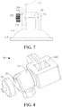
FIG. 8 to FIG. 11 together, thehanger 30 includes a connectingshaft 31, amovable shaft 32 and auniversal ball 33. The connectingshaft 31 is connected to thesupport rod 20, theuniversal ball 33 is connected to the connectingshaft 31 and themovable shaft 32, and themovable shaft 32 can rotate about the center of theuniversal ball 33 relative to the connectingshaft 31. - A ring sleeve is provided at one end of the connecting
shaft 31, and the ring sleeve includes anannular portion 310 and two lockingportions 312. Theannular portion 310 is sleeved on the slidingrod 23, and theannular portion 23 is movable relative to the slidingrod 23 in the length direction of the slidingrod 23. Theannular portion 310 is in a non-closed ring shape, a cross section formed by an inner wall of theannular portion 310 is rectangular, the inner wall of theannular portion 310 is in contact with the slidingrod 23, and the inner wall of theannular portion 310 is adapted to the shape of the slidingrod 23. Agap slot 314 is provided on theannular portion 310. The two lockingportions 312 extend outward from an outer wall of theannular portion 310, the two lockingportions 312 are respectively provided on two ends of thegap slot 314, and there is a gap between the two lockingportions 312. A third throughhole 316 is provided on each of the two lockingportions 312, axes of the two third throughholes 316 coincide with each other. A locking apparatus (not shown) is used to pass through the two third throughholes 316 to press against the two lockingportions 312 to reduce the gap between the two lockingportions 312 and the gap of thegap slot 314, and theannular portion 310 is locked and fixed to thesupport rod 20. Preferably, the locking apparatus uses a bolt and a nut to mate with each other, one end of the bolt passes through the two third throughholes 316, and then the nut is used for locking. - It may be understood that, in some other embodiments, the sliding
rod 23 and the inner wall of theannular portion 310 are disposed as other shapes, for example, polygons with mutually mated sections, so that theannular portion 310 can move only in the length direction of the slidingrod 23 relative to the slidingrod 23, and theannular portion 310 can be prevented from moving toward other directions relative to the slidingrod 23. The "mutually matched" herein does not necessarily require that the cross-section shape of the slidingrod 23 is the same as the shape formed by the inner wall of theannular portion 310. For example, the shape formed by the inner wall of theannular portion 310 may be set as a hexagon, and the cross-section shape of the slidingrod 23 may be set as a quadrilateral connected to the hexagon. In this way, theannular portion 310 can move only in the length direction of the slidingrod 23 relative to the slidingrod 23. The inner walls of the slidingrod 23 and theannular portion 310 may also be elliptical cylindrical tubes that mate with each other, and the elliptical cross-section may also restrict the relative rotation between the two to a certain extent. - A spherical receiving cavity is provided at an other end of the connecting
shaft 31, theuniversal ball 33 is partially received in the receiving cavity, and theuniversal ball 33 is rotatable in any direction in the receiving cavity. A receivinggroove 318 is provided on an upper side of the receiving cavity of the connectingshaft 31, the receivinggroove 318 being in communication with the receiving cavity. A connectingrod 320 is provided at one end of themovable shaft 32, the connectingrod 320 is fixed with theuniversal ball 33, and the connectingrod 320 is rotatable about the center of theuniversal ball 33 in a plurality of directions relative to the connectingshaft 31. An other end of themovable shaft 32 is used to hang the calibration element, thereby implementing multi-directional adjustment of the angle of the calibration element and flexible rotation. When an axis of themovable shaft 32 is perpendicular to an axis of the connectingshaft 31, the connectingrod 320 is received in the receivinggroove 318, so that themovable shaft 32 can be folded relative to the connectingshaft 31, so as to save space and facilitate shipment. A locking structure is provided on the connectingshaft 31, the locking structure includes a lockingscrew 34, and a screw hole adapted to the lockingscrew 34 is provided on the connectingshaft 31. An axis of the screw hole and the axis of the connectingshaft 31 are perpendicular to each other, and the screw hole passes through an outer wall of the connectingshaft 31 to be in communication with the receiving cavity. One end of the lockingscrew 34 passes through the screw hole to abut against and lock theuniversal ball 33, so that relative positions of themovable shaft 32 and the connectingshaft 31 are fixed. - It may be understood that a steering mechanism of the hanger may further be other mechanisms besides the universal ball. For example, a mechanism that can implement steering at a specific angle or steering at any angle falls within the protection scope of the present application. Alternatively, the hanger does not include a steering mechanism, that is, the angle of the calibration element relative to the support rod is fixed when being hung on the hanger.
- In some other embodiments, the
hanger 30 may be disposed as a beam structure, and the beam structure is arranged horizontally. Thecalibration element 40 is hung on the beam structure, and the calibration element can move along the beam structure. The beam structure is sleeved on thesupport rod 20, and the beam structure can move in the length direction of thesupport rod 20, so that thecalibration element 40 can move up and down or left and right. - It should be noted that hanging refers to supporting the
calibration element 40 in any form. For example, thecalibration element 40 may be directly or indirectly fixed to thesupport rod 20 or may be movably connected to thesupport rod 20, as long as thesupport rod 20 supports thecalibration element 40. - Referring to
FIG. 12 , thecalibration element 40 includes aspirit level 41 and apattern plate 42. Thespirit level 41 is disposed on thehanger 30, one end of thespirit level 41 is connected to themovable shaft 32, thespirit level 41 is rotatable about the center of theuniversal ball 33 in a plurality of directions relative to the connectingshaft 31, and thespirit level 41 is configured to keep the axis of themovable shaft 32 horizontal. An other end of thespirit level 41 is connected to thepattern plate 42, and aspirit level bead 410 is mounted to an upper side of thespirit level 41. When thespirit level bead 410 is in a horizontal state, thepattern plate 42 is in a vertical state. It may be understood that, in some other embodiments, thepattern plate 42 may also be a mirror, a laser emitter or the like. - Referring to
FIG. 13 andFIG. 14 , when thesupport rod 20 rotates about thehinge shaft 130 toward thepattern plate 42 to a first position, themain rod 21 abuts against a top face of the column. When thesupport rod 20 rotates about thehinge shaft 130 in a direction away from thepattern plate 42 to a second position, the first limitingface 224 of theangle adjustment structure 22 abuts against an abutting face of the column. The second limitingface 226 of theangle adjustment structure 22 abuts against an arc face of the arc-shapedportion 112. Preferably, when thesupport rod 20 rotates to the first position, an included angle between thesupport rod 20 and the horizontal plane is 0 degrees, which can fold thebase 10 and thesupport rod 20, so as to save a volume of thecalibration bracket 100 not in use and facilitate movement and transportation. When thesupport rod 20 is in the second position, an included angle O between thesupport rod 20 and the horizontal plane is greater than 90 degrees. Preferably, the included angle between thesupport rod 20 and the horizontal plane is set to 135 degrees, that is, the range of angular rotation of thesupport rod 20 is from 0 to 135 degrees, so that thesupport rod 20 is rotatable within a relatively large angle range, and it can be ensured that the limiting between theangle adjustment structure 22 and the limitingportion 11 is reliable. Preferably, the cross section of themain rod 21 is set to be rectangular, and in the first position, one side face of themain rod 21 abuts against the top face of the column. - In using the
calibration bracket 100, thesupport rod 20 is rotated to be adjusted to a proper angle, and theuniversal ball 33 is rotated to cause thespirit level 41 to be in a horizontal state and thepattern plate 42 to be in a vertical state. Thepattern plate 42 is rotatable in a plurality of directions in the vertical state, and then the ring sleeve is moved to adjust a height of thepattern plate 42. - In this embodiment, the
support rod 20 can rotate relative to thebase 10, and themain rod 21, the first limitingface 224, the second limitingface 226, the column and the arc-shapedportion 112 are limited to control the range of angular rotation of thesupport rod 20. The joint 40 may be adjusted to maintain thepattern plate 42 vertical and adjust angles in a plurality of directions, and thepattern plate 42 can move the ring sleeve of thehanger 30 to adjust the height when being in a vertical state. Thesupport rod 20 can freely adjust the angle within the range of angular rotation, and thepattern plate 42 can adjust the direction and height when being in the vertical state, which can meet various special calibration angles. - Finally, it should be noted that the foregoing embodiments are merely used for describing the technical solutions of the present invention, but are not intended to limit the present invention. Under the concept of the present invention, the technical features in the foregoing embodiments or different embodiments may be combined, the steps may be implemented in any sequence, and there may be many other changes in different aspects of the present invention as described above. For brevity, those are not provided in detail. Although the present invention is described in detail with reference to the foregoing embodiments, a person of ordinary skill in the art should understand that they may still make modifications to the technical solutions described in the foregoing embodiments or make equivalent replacements to some technical features thereof, without departing from the scope of the technical solutions of the embodiments of the present invention.
Claims (15)
- A calibration bracket, comprising:a base;a support rod comprising a main rod and an angle adjustment structure, the main rod being connected to the angle adjustment structure, and the angle adjustment structure being movably connected to the base and being configured to adjust an angle of the main rod relative to a ground plane on which the base is located;anda hanger mounted to the support rod, the hanger being configured to hang a calibration element, the calibration element being configured to calibrate a device in a driver assistant system of a vehicle.
- The calibration bracket according to claim 1, wherein
the base comprises a limiting portion configured to limit a range of movement of the angle adjustment structure. - The calibration bracket according to claim 1 or 2, wherein
the base comprises a positioning portion configured to fix the angle adjustment structure to a specific position within the range of movement or fix the angle adjustment structure to any position within the range of movement. - The calibration bracket according to claim 2 or 3, whereinthe limiting portion comprises a top face and an abutting face; andin a first position, the main rod abuts against the top face, and in a second position, the angle adjustment structure abuts against the abutting face, the range of movement of the angle adjustment structure being between the first position and the second position.
- The calibration bracket according to claim 4, wherein
the top face is substantially parallel to the ground plane on which the base is located. - The calibration bracket according to claim 4, wherein
when the angle adjustment structure abuts against the abutting face, an angle of the support rod relative to the ground plane on which the base is located is greater than 90 degrees. - The calibration bracket according to any of claims 1 to 6, whereinthe base comprises two hinge portions;the limiting portion is disposed between the two hinge portions; anda first through hole is provided on each of the two hinge portions, and a second through hole is provided on the limiting portion, an axis of the second through hole coinciding with axes of the two first through holes, and a hinge shaft passing through the first through holes and the second through hole to connect the limiting portion to the two hinge portions.
- The calibration bracket according to any of claims 1 to 7, whereinthe hanger comprises a connecting shaft and a movable shaft;the connecting shaft is configured to be connected to the support rod; andthe movable shaft is connected to the connecting shaft, the movable shaft is rotatable relative to the connecting shaft to adjust an angle of the movable shaft relative to the support rod, and the connecting shaft is configured to hang the calibration element.
- The calibration bracket according to claim 8, whereina receiving cavity is provided on the connecting shaft, the receiving cavity being configured to receive a universal ball, the universal ball being rotatable in any direction in the receiving cavity; andthe movable shaft is connected to the universal ball and is rotatable about a center of the universal ball relative to the connecting shaft.
- The calibration bracket according to claim 8 or 9, whereinthe hanger further comprises a locking structure; andthe locking structure is configured to fix a position of the movable shaft relative to the connecting shaft.
- The calibration bracket according to claim 10, wherein
the locking structure comprises a locking screw, a screw hole mated with the locking screw being provided on the connecting shaft, the locking screw passing through the screw hole to abut against the universal ball to fix the position of the movable shaft relative to the connecting shaft. - The calibration bracket according to claim 11, whereina receiving groove is provided on the connecting shaft, the receiving groove being in communication with the receiving cavity; andwhen an axis of the connecting shaft is perpendicular to an axis of the movable shaft, the movable shaft is received in the receiving groove.
- The calibration bracket according to any of claims 8 to 12, wherein
a spirit level is disposed on the hanger, the spirit level being configured to keep the axis of the movable shaft horizontal. - The calibration bracket according to any of claims 8 to 13, wherein
the support rod is inserted into the connecting shaft. - The calibration bracket according to any of claims 8 to 14, wherein
the connecting shaft is movable in a length direction of the support rod.
Applications Claiming Priority (2)
| Application Number | Priority Date | Filing Date | Title |
|---|---|---|---|
| CN201910214908.5A CN111721347A (en) | 2019-03-20 | 2019-03-20 | A calibration bracket |
| PCT/CN2020/080445 WO2020187323A1 (en) | 2019-03-20 | 2020-03-20 | Calibration bracket |
Publications (3)
| Publication Number | Publication Date |
|---|---|
| EP3936831A1 true EP3936831A1 (en) | 2022-01-12 |
| EP3936831A4 EP3936831A4 (en) | 2022-05-04 |
| EP3936831B1 EP3936831B1 (en) | 2024-07-31 |
Family
ID=72519676
Family Applications (1)
| Application Number | Title | Priority Date | Filing Date |
|---|---|---|---|
| EP20772809.8A Active EP3936831B1 (en) | 2019-03-20 | 2020-03-20 | Calibration bracket |
Country Status (4)
| Country | Link |
|---|---|
| US (1) | US12487107B2 (en) |
| EP (1) | EP3936831B1 (en) |
| CN (1) | CN111721347A (en) |
| WO (1) | WO2020187323A1 (en) |
Families Citing this family (5)
| Publication number | Priority date | Publication date | Assignee | Title |
|---|---|---|---|---|
| CN112228745A (en) * | 2020-10-20 | 2021-01-15 | 温州万真网络科技有限公司 | Underwater video transmission device |
| US11800055B2 (en) * | 2020-12-23 | 2023-10-24 | Plantronics, Inc. | Adjustable mounting system for a telepresence device |
| CN114278845B (en) * | 2021-12-15 | 2024-02-13 | 中建港航局集团有限公司 | Mounting structure of container yard monitor rod |
| CN115717671A (en) * | 2022-10-26 | 2023-02-28 | 广西壮族自治区生态环境监测中心 | A three-dimensional monitoring device for atmospheric fine particles |
| CN119439638B (en) * | 2024-10-24 | 2025-11-28 | 上海琮光半导体科技有限公司 | Calibration mechanism of photoetching machine |
Family Cites Families (26)
| Publication number | Priority date | Publication date | Assignee | Title |
|---|---|---|---|---|
| US4930340A (en) * | 1989-09-19 | 1990-06-05 | Kelsey-Hayes Company | Calibration bracket for vehicle height sensor |
| US5279488A (en) * | 1992-07-09 | 1994-01-18 | James Fleming | Adjustable workstation for vehicles |
| DE202005000768U1 (en) * | 2004-11-29 | 2005-03-31 | Richter Harald | Device with universally adjustable retaining plate |
| CN201141918Y (en) * | 2008-01-04 | 2008-10-29 | 核工业北京地质研究院 | Standard source holder for calibrating radioactive radiometers |
| TWI347297B (en) * | 2008-10-09 | 2011-08-21 | Hon Hai Prec Ind Co Ltd | Height adjustable stand |
| JP2011219352A (en) | 2010-03-24 | 2011-11-04 | Nippon Electric Glass Co Ltd | Method for manufacturing glass plate laminated body, glass plate bonding method, and glass plate laminated body manufactured using the manufacturing method |
| CN202089156U (en) * | 2011-05-24 | 2011-12-28 | 温岭东方红车料有限公司 | Resilient clamp for connecting bicycle saddle and tool kit |
| CN102840427B (en) * | 2012-08-27 | 2014-05-28 | 北京无线电计量测试研究所 | Bracket for calibrating field uniformity of transient electromagnetic field |
| CN102830288B (en) * | 2012-08-27 | 2014-11-19 | 北京无线电计量测试研究所 | Support for calibrating field uniformity of transient electromagnetic field |
| CN202791221U (en) * | 2012-09-03 | 2013-03-13 | 上海望望文化发展有限公司 | Telescopic touch displayer |
| CN103498999B (en) * | 2013-09-26 | 2016-04-20 | 深圳宝龙达信息技术股份有限公司 | Electronic device stand |
| CN103645455B (en) * | 2013-12-19 | 2016-08-24 | 北京无线电计量测试研究所 | Probe correcting device |
| CN104313987B (en) * | 2014-10-22 | 2016-07-06 | 江苏苏科畅联科技有限公司 | The mobile caliberating device of a kind of FWD and mobile scaling method |
| US9794552B1 (en) * | 2014-10-31 | 2017-10-17 | Lytx, Inc. | Calibration of advanced driver assistance system |
| CN204845765U (en) * | 2015-07-06 | 2015-12-09 | 陈工 | A support for dull and stereotyped electronic equipment |
| CN105300711B (en) * | 2015-10-10 | 2018-01-30 | 深圳市元征科技股份有限公司 | Four-wheel position finder caliberating device |
| CN105758558A (en) * | 2016-03-24 | 2016-07-13 | 中国科学院寒区旱区环境与工程研究所 | Thermistor temperature sensor calibrating apparatus |
| CN205748613U (en) * | 2016-06-22 | 2016-11-30 | 浙江理工大学 | A kind of small-range parallel girder load sensor demarcates support |
| CN207231455U (en) * | 2017-09-28 | 2018-04-13 | 公安部四川消防研究所 | Vertical adjustment base applied to the Experimental Calibration system of vertical Light deformation amount |
| CN207318527U (en) * | 2017-10-21 | 2018-05-04 | 福建新大陆支付技术有限公司 | Non-contact card adjustable height test bracket |
| CN107727036A (en) * | 2017-11-28 | 2018-02-23 | 黄石佳鼎自动化科技有限公司 | A kind of demarcation support of displacement transducer |
| CN107966690B (en) * | 2018-01-12 | 2024-05-24 | 深圳市道通科技股份有限公司 | Vehicle-mounted radar calibration equipment |
| CN109278066B (en) * | 2018-10-30 | 2023-11-03 | 武汉工程大学 | A multi-robot base coordinate system geometric calibration tooling and calibration method |
| CN210036785U (en) * | 2019-03-20 | 2020-02-07 | 深圳市道通合创软件开发有限公司 | Calibration support |
| PL3929542T3 (en) * | 2020-06-26 | 2023-11-06 | Sick Engineering Gmbh | Testing an ultrasound flow meter |
| US20220049954A1 (en) * | 2020-08-12 | 2022-02-17 | Autel Intelligent Technology Corp., Ltd. | Calibration system and calibration bracket thereof |
-
2019
- 2019-03-20 CN CN201910214908.5A patent/CN111721347A/en active Pending
-
2020
- 2020-03-20 WO PCT/CN2020/080445 patent/WO2020187323A1/en not_active Ceased
- 2020-03-20 EP EP20772809.8A patent/EP3936831B1/en active Active
-
2021
- 2021-09-10 US US17/447,370 patent/US12487107B2/en active Active
Also Published As
| Publication number | Publication date |
|---|---|
| CN111721347A (en) | 2020-09-29 |
| US20210404846A1 (en) | 2021-12-30 |
| EP3936831B1 (en) | 2024-07-31 |
| US12487107B2 (en) | 2025-12-02 |
| EP3936831A4 (en) | 2022-05-04 |
| WO2020187323A1 (en) | 2020-09-24 |
Similar Documents
| Publication | Publication Date | Title |
|---|---|---|
| US12487107B2 (en) | Calibration bracket | |
| US20230011610A1 (en) | Calibration bracket | |
| CN215767682U (en) | Calibration equipment and calibration system | |
| US5184521A (en) | Gyroscopically stabilized apparatus | |
| US11307294B2 (en) | Scanning assembly for a detection system | |
| US6154317A (en) | Device for stabilizing of a remotely controlled sensor, like a camera | |
| CN104696690B (en) | Onboard holder | |
| US20100229452A1 (en) | Firearm system having camera unit with adjustable optical axis | |
| WO2017129137A1 (en) | Gimbal of unmanned aerial vehicle and bearing support thereof | |
| US20170146893A1 (en) | Gimbal locking device and gimbal assembly using same | |
| CA1232443A (en) | Sightline stabilisation apparatus | |
| JP3695096B2 (en) | Hot wire sensor | |
| US20040159754A1 (en) | Universal adjusting mechanism for tripods | |
| US6202571B1 (en) | Lock mechanism for folding leg | |
| US10314192B2 (en) | Display apparatus | |
| GB2322437A (en) | Pivotable search device | |
| US20110198467A1 (en) | Adjustable mount holder | |
| CN210036785U (en) | Calibration support | |
| WO2020147723A1 (en) | Laser emitter, and apparatus and method for aligning calibration device | |
| KR101513199B1 (en) | Altitude adjusting apparatus of equatorial mount for astronomical telescope | |
| CN207830863U (en) | PTZ level regulating device | |
| US6853349B1 (en) | Method and device for prevention of gimbal-locking | |
| ES3015608T3 (en) | Arrangement and method for autoalignment of a stabilized subsystem | |
| CN211824509U (en) | Calibration support | |
| KR101848205B1 (en) | Apparatus for connecting hanger |
Legal Events
| Date | Code | Title | Description |
|---|---|---|---|
| STAA | Information on the status of an ep patent application or granted ep patent |
Free format text: STATUS: THE INTERNATIONAL PUBLICATION HAS BEEN MADE |
|
| PUAI | Public reference made under article 153(3) epc to a published international application that has entered the european phase |
Free format text: ORIGINAL CODE: 0009012 |
|
| STAA | Information on the status of an ep patent application or granted ep patent |
Free format text: STATUS: REQUEST FOR EXAMINATION WAS MADE |
|
| 17P | Request for examination filed |
Effective date: 20211004 |
|
| AK | Designated contracting states |
Kind code of ref document: A1 Designated state(s): AL AT BE BG CH CY CZ DE DK EE ES FI FR GB GR HR HU IE IS IT LI LT LU LV MC MK MT NL NO PL PT RO RS SE SI SK SM TR |
|
| A4 | Supplementary search report drawn up and despatched |
Effective date: 20220407 |
|
| RIC1 | Information provided on ipc code assigned before grant |
Ipc: F16M 11/20 20060101ALI20220401BHEP Ipc: F16M 11/14 20060101ALI20220401BHEP Ipc: F16M 11/24 20060101ALI20220401BHEP Ipc: G01S 7/52 20060101ALI20220401BHEP Ipc: G01S 7/497 20060101ALI20220401BHEP Ipc: G01S 7/40 20060101ALI20220401BHEP Ipc: G01D 11/30 20060101ALI20220401BHEP Ipc: G01D 18/00 20060101AFI20220401BHEP |
|
| DAV | Request for validation of the european patent (deleted) | ||
| DAX | Request for extension of the european patent (deleted) | ||
| RIC1 | Information provided on ipc code assigned before grant |
Ipc: F16M 11/20 20060101ALI20240426BHEP Ipc: F16M 11/14 20060101ALI20240426BHEP Ipc: F16M 11/24 20060101ALI20240426BHEP Ipc: G01S 7/52 20060101ALI20240426BHEP Ipc: G01S 7/497 20060101ALI20240426BHEP Ipc: G01S 7/40 20060101ALI20240426BHEP Ipc: G01D 11/30 20060101ALI20240426BHEP Ipc: G01D 18/00 20060101AFI20240426BHEP |
|
| GRAP | Despatch of communication of intention to grant a patent |
Free format text: ORIGINAL CODE: EPIDOSNIGR1 |
|
| STAA | Information on the status of an ep patent application or granted ep patent |
Free format text: STATUS: GRANT OF PATENT IS INTENDED |
|
| GRAS | Grant fee paid |
Free format text: ORIGINAL CODE: EPIDOSNIGR3 |
|
| GRAA | (expected) grant |
Free format text: ORIGINAL CODE: 0009210 |
|
| STAA | Information on the status of an ep patent application or granted ep patent |
Free format text: STATUS: THE PATENT HAS BEEN GRANTED |
|
| INTG | Intention to grant announced |
Effective date: 20240604 |
|
| AK | Designated contracting states |
Kind code of ref document: B1 Designated state(s): AL AT BE BG CH CY CZ DE DK EE ES FI FR GB GR HR HU IE IS IT LI LT LU LV MC MK MT NL NO PL PT RO RS SE SI SK SM TR |
|
| REG | Reference to a national code |
Ref country code: CH Ref legal event code: EP Ref country code: GB Ref legal event code: FG4D |
|
| REG | Reference to a national code |
Ref country code: DE Ref legal event code: R096 Ref document number: 602020034928 Country of ref document: DE |
|
| REG | Reference to a national code |
Ref country code: IE Ref legal event code: FG4D |
|
| REG | Reference to a national code |
Ref country code: LT Ref legal event code: MG9D |
|
| REG | Reference to a national code |
Ref country code: NL Ref legal event code: MP Effective date: 20240731 |
|
| PG25 | Lapsed in a contracting state [announced via postgrant information from national office to epo] |
Ref country code: PT Free format text: LAPSE BECAUSE OF FAILURE TO SUBMIT A TRANSLATION OF THE DESCRIPTION OR TO PAY THE FEE WITHIN THE PRESCRIBED TIME-LIMIT Effective date: 20241202 |
|
| REG | Reference to a national code |
Ref country code: AT Ref legal event code: MK05 Ref document number: 1708857 Country of ref document: AT Kind code of ref document: T Effective date: 20240731 |
|
| PG25 | Lapsed in a contracting state [announced via postgrant information from national office to epo] |
Ref country code: PT Free format text: LAPSE BECAUSE OF FAILURE TO SUBMIT A TRANSLATION OF THE DESCRIPTION OR TO PAY THE FEE WITHIN THE PRESCRIBED TIME-LIMIT Effective date: 20241202 |
|
| PG25 | Lapsed in a contracting state [announced via postgrant information from national office to epo] |
Ref country code: NO Free format text: LAPSE BECAUSE OF FAILURE TO SUBMIT A TRANSLATION OF THE DESCRIPTION OR TO PAY THE FEE WITHIN THE PRESCRIBED TIME-LIMIT Effective date: 20241031 |
|
| PG25 | Lapsed in a contracting state [announced via postgrant information from national office to epo] |
Ref country code: FI Free format text: LAPSE BECAUSE OF FAILURE TO SUBMIT A TRANSLATION OF THE DESCRIPTION OR TO PAY THE FEE WITHIN THE PRESCRIBED TIME-LIMIT Effective date: 20240731 Ref country code: NL Free format text: LAPSE BECAUSE OF FAILURE TO SUBMIT A TRANSLATION OF THE DESCRIPTION OR TO PAY THE FEE WITHIN THE PRESCRIBED TIME-LIMIT Effective date: 20240731 Ref country code: GR Free format text: LAPSE BECAUSE OF FAILURE TO SUBMIT A TRANSLATION OF THE DESCRIPTION OR TO PAY THE FEE WITHIN THE PRESCRIBED TIME-LIMIT Effective date: 20241101 Ref country code: PL Free format text: LAPSE BECAUSE OF FAILURE TO SUBMIT A TRANSLATION OF THE DESCRIPTION OR TO PAY THE FEE WITHIN THE PRESCRIBED TIME-LIMIT Effective date: 20240731 |
|
| PG25 | Lapsed in a contracting state [announced via postgrant information from national office to epo] |
Ref country code: BG Free format text: LAPSE BECAUSE OF FAILURE TO SUBMIT A TRANSLATION OF THE DESCRIPTION OR TO PAY THE FEE WITHIN THE PRESCRIBED TIME-LIMIT Effective date: 20240731 |
|
| PG25 | Lapsed in a contracting state [announced via postgrant information from national office to epo] |
Ref country code: LV Free format text: LAPSE BECAUSE OF FAILURE TO SUBMIT A TRANSLATION OF THE DESCRIPTION OR TO PAY THE FEE WITHIN THE PRESCRIBED TIME-LIMIT Effective date: 20240731 |
|
| PG25 | Lapsed in a contracting state [announced via postgrant information from national office to epo] |
Ref country code: IS Free format text: LAPSE BECAUSE OF FAILURE TO SUBMIT A TRANSLATION OF THE DESCRIPTION OR TO PAY THE FEE WITHIN THE PRESCRIBED TIME-LIMIT Effective date: 20241130 Ref country code: AT Free format text: LAPSE BECAUSE OF FAILURE TO SUBMIT A TRANSLATION OF THE DESCRIPTION OR TO PAY THE FEE WITHIN THE PRESCRIBED TIME-LIMIT Effective date: 20240731 |
|
| PG25 | Lapsed in a contracting state [announced via postgrant information from national office to epo] |
Ref country code: HR Free format text: LAPSE BECAUSE OF FAILURE TO SUBMIT A TRANSLATION OF THE DESCRIPTION OR TO PAY THE FEE WITHIN THE PRESCRIBED TIME-LIMIT Effective date: 20240731 |
|
| PG25 | Lapsed in a contracting state [announced via postgrant information from national office to epo] |
Ref country code: RS Free format text: LAPSE BECAUSE OF FAILURE TO SUBMIT A TRANSLATION OF THE DESCRIPTION OR TO PAY THE FEE WITHIN THE PRESCRIBED TIME-LIMIT Effective date: 20241031 Ref country code: ES Free format text: LAPSE BECAUSE OF FAILURE TO SUBMIT A TRANSLATION OF THE DESCRIPTION OR TO PAY THE FEE WITHIN THE PRESCRIBED TIME-LIMIT Effective date: 20240731 |
|
| PG25 | Lapsed in a contracting state [announced via postgrant information from national office to epo] |
Ref country code: RS Free format text: LAPSE BECAUSE OF FAILURE TO SUBMIT A TRANSLATION OF THE DESCRIPTION OR TO PAY THE FEE WITHIN THE PRESCRIBED TIME-LIMIT Effective date: 20241031 Ref country code: PL Free format text: LAPSE BECAUSE OF FAILURE TO SUBMIT A TRANSLATION OF THE DESCRIPTION OR TO PAY THE FEE WITHIN THE PRESCRIBED TIME-LIMIT Effective date: 20240731 Ref country code: NO Free format text: LAPSE BECAUSE OF FAILURE TO SUBMIT A TRANSLATION OF THE DESCRIPTION OR TO PAY THE FEE WITHIN THE PRESCRIBED TIME-LIMIT Effective date: 20241031 Ref country code: NL Free format text: LAPSE BECAUSE OF FAILURE TO SUBMIT A TRANSLATION OF THE DESCRIPTION OR TO PAY THE FEE WITHIN THE PRESCRIBED TIME-LIMIT Effective date: 20240731 Ref country code: LV Free format text: LAPSE BECAUSE OF FAILURE TO SUBMIT A TRANSLATION OF THE DESCRIPTION OR TO PAY THE FEE WITHIN THE PRESCRIBED TIME-LIMIT Effective date: 20240731 Ref country code: IS Free format text: LAPSE BECAUSE OF FAILURE TO SUBMIT A TRANSLATION OF THE DESCRIPTION OR TO PAY THE FEE WITHIN THE PRESCRIBED TIME-LIMIT Effective date: 20241130 Ref country code: HR Free format text: LAPSE BECAUSE OF FAILURE TO SUBMIT A TRANSLATION OF THE DESCRIPTION OR TO PAY THE FEE WITHIN THE PRESCRIBED TIME-LIMIT Effective date: 20240731 Ref country code: GR Free format text: LAPSE BECAUSE OF FAILURE TO SUBMIT A TRANSLATION OF THE DESCRIPTION OR TO PAY THE FEE WITHIN THE PRESCRIBED TIME-LIMIT Effective date: 20241101 Ref country code: FI Free format text: LAPSE BECAUSE OF FAILURE TO SUBMIT A TRANSLATION OF THE DESCRIPTION OR TO PAY THE FEE WITHIN THE PRESCRIBED TIME-LIMIT Effective date: 20240731 Ref country code: ES Free format text: LAPSE BECAUSE OF FAILURE TO SUBMIT A TRANSLATION OF THE DESCRIPTION OR TO PAY THE FEE WITHIN THE PRESCRIBED TIME-LIMIT Effective date: 20240731 Ref country code: BG Free format text: LAPSE BECAUSE OF FAILURE TO SUBMIT A TRANSLATION OF THE DESCRIPTION OR TO PAY THE FEE WITHIN THE PRESCRIBED TIME-LIMIT Effective date: 20240731 Ref country code: AT Free format text: LAPSE BECAUSE OF FAILURE TO SUBMIT A TRANSLATION OF THE DESCRIPTION OR TO PAY THE FEE WITHIN THE PRESCRIBED TIME-LIMIT Effective date: 20240731 |
|
| PG25 | Lapsed in a contracting state [announced via postgrant information from national office to epo] |
Ref country code: RO Free format text: LAPSE BECAUSE OF FAILURE TO SUBMIT A TRANSLATION OF THE DESCRIPTION OR TO PAY THE FEE WITHIN THE PRESCRIBED TIME-LIMIT Effective date: 20240731 Ref country code: SM Free format text: LAPSE BECAUSE OF FAILURE TO SUBMIT A TRANSLATION OF THE DESCRIPTION OR TO PAY THE FEE WITHIN THE PRESCRIBED TIME-LIMIT Effective date: 20240731 Ref country code: DK Free format text: LAPSE BECAUSE OF FAILURE TO SUBMIT A TRANSLATION OF THE DESCRIPTION OR TO PAY THE FEE WITHIN THE PRESCRIBED TIME-LIMIT Effective date: 20240731 |
|
| PG25 | Lapsed in a contracting state [announced via postgrant information from national office to epo] |
Ref country code: EE Free format text: LAPSE BECAUSE OF FAILURE TO SUBMIT A TRANSLATION OF THE DESCRIPTION OR TO PAY THE FEE WITHIN THE PRESCRIBED TIME-LIMIT Effective date: 20240731 |
|
| PG25 | Lapsed in a contracting state [announced via postgrant information from national office to epo] |
Ref country code: CZ Free format text: LAPSE BECAUSE OF FAILURE TO SUBMIT A TRANSLATION OF THE DESCRIPTION OR TO PAY THE FEE WITHIN THE PRESCRIBED TIME-LIMIT Effective date: 20240731 |
|
| PG25 | Lapsed in a contracting state [announced via postgrant information from national office to epo] |
Ref country code: IT Free format text: LAPSE BECAUSE OF FAILURE TO SUBMIT A TRANSLATION OF THE DESCRIPTION OR TO PAY THE FEE WITHIN THE PRESCRIBED TIME-LIMIT Effective date: 20240731 Ref country code: SK Free format text: LAPSE BECAUSE OF FAILURE TO SUBMIT A TRANSLATION OF THE DESCRIPTION OR TO PAY THE FEE WITHIN THE PRESCRIBED TIME-LIMIT Effective date: 20240731 |
|
| REG | Reference to a national code |
Ref country code: DE Ref legal event code: R097 Ref document number: 602020034928 Country of ref document: DE |
|
| PLBE | No opposition filed within time limit |
Free format text: ORIGINAL CODE: 0009261 |
|
| STAA | Information on the status of an ep patent application or granted ep patent |
Free format text: STATUS: NO OPPOSITION FILED WITHIN TIME LIMIT |
|
| 26N | No opposition filed |
Effective date: 20250501 |
|
| PG25 | Lapsed in a contracting state [announced via postgrant information from national office to epo] |
Ref country code: SE Free format text: LAPSE BECAUSE OF FAILURE TO SUBMIT A TRANSLATION OF THE DESCRIPTION OR TO PAY THE FEE WITHIN THE PRESCRIBED TIME-LIMIT Effective date: 20240731 |
|
| PG25 | Lapsed in a contracting state [announced via postgrant information from national office to epo] |
Ref country code: MC Free format text: LAPSE BECAUSE OF FAILURE TO SUBMIT A TRANSLATION OF THE DESCRIPTION OR TO PAY THE FEE WITHIN THE PRESCRIBED TIME-LIMIT Effective date: 20240731 |
|
| REG | Reference to a national code |
Ref country code: CH Ref legal event code: H13 Free format text: ST27 STATUS EVENT CODE: U-0-0-H10-H13 (AS PROVIDED BY THE NATIONAL OFFICE) Effective date: 20251023 |
|
| PG25 | Lapsed in a contracting state [announced via postgrant information from national office to epo] |
Ref country code: LU Free format text: LAPSE BECAUSE OF NON-PAYMENT OF DUE FEES Effective date: 20250320 |
|
| REG | Reference to a national code |
Ref country code: BE Ref legal event code: MM Effective date: 20250331 |
|
| PG25 | Lapsed in a contracting state [announced via postgrant information from national office to epo] |
Ref country code: BE Free format text: LAPSE BECAUSE OF NON-PAYMENT OF DUE FEES Effective date: 20250331 |
|
| PG25 | Lapsed in a contracting state [announced via postgrant information from national office to epo] |
Ref country code: CH Free format text: LAPSE BECAUSE OF NON-PAYMENT OF DUE FEES Effective date: 20250331 |
|
| PG25 | Lapsed in a contracting state [announced via postgrant information from national office to epo] |
Ref country code: IE Free format text: LAPSE BECAUSE OF NON-PAYMENT OF DUE FEES Effective date: 20250320 |
|
| PGFP | Annual fee paid to national office [announced via postgrant information from national office to epo] |
Ref country code: GB Payment date: 20260324 Year of fee payment: 7 |
|
| PGFP | Annual fee paid to national office [announced via postgrant information from national office to epo] |
Ref country code: DE Payment date: 20260320 Year of fee payment: 7 |
|
| PGFP | Annual fee paid to national office [announced via postgrant information from national office to epo] |
Ref country code: FR Payment date: 20260324 Year of fee payment: 7 |