EP3936799A1 - Refrigerator - Google Patents
Refrigerator Download PDFInfo
- Publication number
- EP3936799A1 EP3936799A1 EP21183731.5A EP21183731A EP3936799A1 EP 3936799 A1 EP3936799 A1 EP 3936799A1 EP 21183731 A EP21183731 A EP 21183731A EP 3936799 A1 EP3936799 A1 EP 3936799A1
- Authority
- EP
- European Patent Office
- Prior art keywords
- space
- insulating
- door
- contact
- refrigerator
- Prior art date
- Legal status (The legal status is an assumption and is not a legal conclusion. Google has not performed a legal analysis and makes no representation as to the accuracy of the status listed.)
- Pending
Links
- 239000012212 insulator Substances 0.000 claims abstract description 29
- 230000001154 acute effect Effects 0.000 claims description 4
- 238000005187 foaming Methods 0.000 description 111
- 239000007788 liquid Substances 0.000 description 103
- 238000002347 injection Methods 0.000 description 61
- 239000007924 injection Substances 0.000 description 61
- 230000008878 coupling Effects 0.000 description 40
- 238000010168 coupling process Methods 0.000 description 40
- 238000005859 coupling reaction Methods 0.000 description 40
- 230000004308 accommodation Effects 0.000 description 24
- 125000006850 spacer group Chemical group 0.000 description 10
- 239000006260 foam Substances 0.000 description 5
- 239000000463 material Substances 0.000 description 4
- 230000005540 biological transmission Effects 0.000 description 3
- 235000013305 food Nutrition 0.000 description 3
- 238000009434 installation Methods 0.000 description 3
- 238000000034 method Methods 0.000 description 3
- 230000004048 modification Effects 0.000 description 3
- 238000012986 modification Methods 0.000 description 3
- 230000008569 process Effects 0.000 description 3
- 230000001133 acceleration Effects 0.000 description 2
- 230000007423 decrease Effects 0.000 description 2
- 238000007599 discharging Methods 0.000 description 2
- 239000011521 glass Substances 0.000 description 2
- 238000009413 insulation Methods 0.000 description 2
- 229920003023 plastic Polymers 0.000 description 2
- 239000000853 adhesive Substances 0.000 description 1
- 230000001070 adhesive effect Effects 0.000 description 1
- 230000004888 barrier function Effects 0.000 description 1
- 230000015572 biosynthetic process Effects 0.000 description 1
- 230000001419 dependent effect Effects 0.000 description 1
- 230000000994 depressogenic effect Effects 0.000 description 1
- 230000008014 freezing Effects 0.000 description 1
- 238000007710 freezing Methods 0.000 description 1
- NLYAJNPCOHFWQQ-UHFFFAOYSA-N kaolin Chemical compound O.O.O=[Al]O[Si](=O)O[Si](=O)O[Al]=O NLYAJNPCOHFWQQ-UHFFFAOYSA-N 0.000 description 1
- 239000003507 refrigerant Substances 0.000 description 1
- 238000005057 refrigeration Methods 0.000 description 1
- 239000000243 solution Substances 0.000 description 1
- XLYOFNOQVPJJNP-UHFFFAOYSA-N water Substances O XLYOFNOQVPJJNP-UHFFFAOYSA-N 0.000 description 1
Images


Classifications
-
- F—MECHANICAL ENGINEERING; LIGHTING; HEATING; WEAPONS; BLASTING
- F25—REFRIGERATION OR COOLING; COMBINED HEATING AND REFRIGERATION SYSTEMS; HEAT PUMP SYSTEMS; MANUFACTURE OR STORAGE OF ICE; LIQUEFACTION SOLIDIFICATION OF GASES
- F25D—REFRIGERATORS; COLD ROOMS; ICE-BOXES; COOLING OR FREEZING APPARATUS NOT OTHERWISE PROVIDED FOR
- F25D23/00—General constructional features
- F25D23/02—Doors; Covers
-
- F—MECHANICAL ENGINEERING; LIGHTING; HEATING; WEAPONS; BLASTING
- F25—REFRIGERATION OR COOLING; COMBINED HEATING AND REFRIGERATION SYSTEMS; HEAT PUMP SYSTEMS; MANUFACTURE OR STORAGE OF ICE; LIQUEFACTION SOLIDIFICATION OF GASES
- F25D—REFRIGERATORS; COLD ROOMS; ICE-BOXES; COOLING OR FREEZING APPARATUS NOT OTHERWISE PROVIDED FOR
- F25D11/00—Self-contained movable devices, e.g. domestic refrigerators
-
- F—MECHANICAL ENGINEERING; LIGHTING; HEATING; WEAPONS; BLASTING
- F25—REFRIGERATION OR COOLING; COMBINED HEATING AND REFRIGERATION SYSTEMS; HEAT PUMP SYSTEMS; MANUFACTURE OR STORAGE OF ICE; LIQUEFACTION SOLIDIFICATION OF GASES
- F25D—REFRIGERATORS; COLD ROOMS; ICE-BOXES; COOLING OR FREEZING APPARATUS NOT OTHERWISE PROVIDED FOR
- F25D1/00—Devices using naturally cold air or cold water
-
- F—MECHANICAL ENGINEERING; LIGHTING; HEATING; WEAPONS; BLASTING
- F25—REFRIGERATION OR COOLING; COMBINED HEATING AND REFRIGERATION SYSTEMS; HEAT PUMP SYSTEMS; MANUFACTURE OR STORAGE OF ICE; LIQUEFACTION SOLIDIFICATION OF GASES
- F25D—REFRIGERATORS; COLD ROOMS; ICE-BOXES; COOLING OR FREEZING APPARATUS NOT OTHERWISE PROVIDED FOR
- F25D23/00—General constructional features
- F25D23/02—Doors; Covers
- F25D23/028—Details
-
- F—MECHANICAL ENGINEERING; LIGHTING; HEATING; WEAPONS; BLASTING
- F25—REFRIGERATION OR COOLING; COMBINED HEATING AND REFRIGERATION SYSTEMS; HEAT PUMP SYSTEMS; MANUFACTURE OR STORAGE OF ICE; LIQUEFACTION SOLIDIFICATION OF GASES
- F25D—REFRIGERATORS; COLD ROOMS; ICE-BOXES; COOLING OR FREEZING APPARATUS NOT OTHERWISE PROVIDED FOR
- F25D2201/00—Insulation
- F25D2201/10—Insulation with respect to heat
- F25D2201/12—Insulation with respect to heat using an insulating packing material
- F25D2201/126—Insulation with respect to heat using an insulating packing material of cellular type
-
- F—MECHANICAL ENGINEERING; LIGHTING; HEATING; WEAPONS; BLASTING
- F25—REFRIGERATION OR COOLING; COMBINED HEATING AND REFRIGERATION SYSTEMS; HEAT PUMP SYSTEMS; MANUFACTURE OR STORAGE OF ICE; LIQUEFACTION SOLIDIFICATION OF GASES
- F25D—REFRIGERATORS; COLD ROOMS; ICE-BOXES; COOLING OR FREEZING APPARATUS NOT OTHERWISE PROVIDED FOR
- F25D23/00—General constructional features
- F25D23/06—Walls
- F25D23/065—Details
- F25D23/066—Liners
Definitions
- This specification relates to a refrigerator.
- refrigerators are home appliances for storing foods at low temperature in an inner storage space covered by a refrigerator door.
- the inside of the storage space is cooled using cool air that is generated by being heat-exchanged with a refrigerant circulated in a refrigeration cycle to store the foods in an optimal state.
- the refrigerator door Since the storage space is sealed by the refrigerator door, the refrigerator door has to have an insulating function.
- the refrigerator door may define an insulating space therein, and a foaming liquid injected through an injection hole is hardened to provide an insulator in the insulating space.
- a door for a home appliance is disclosed in Korean Patent Publication No. 10-2017-0019341 (Published on February 21, 2017 ), which is a prior art document.
- the door may include a panel assembly and a frame assembly which has an opening and to which an edge of the panel assembly is connected to support panel assembly, and a foaming space is defined between the frame assembly and the panel assembly to accommodate an insulator.
- a plurality of foam injection holes into which the insulator is injected are provided in a top or bottom surface of the frame assembly.
- the foam injection holes are defined in the top or bottom surface of the frame assembly, and the foaming liquid passing through the foam injection holes are directly introduced into the foaming space.
- the hardened foaming liquid may act as resistance around the foam injection holes since it collides with the surrounding structures and may thereby reduce an injection rate of the foaming liquid. Finally, the foaming liquid may not be uniformly distributed into the foaming space.
- the foaming liquid spread to the surroundings may act as resistance of the foaming liquid that is to be subsequently injected.
- the frame assembly includes a rear frame disposed on a rear surface of the door and a side frame connected to the rear frame to define the foaming space.
- the panel assembly include a front panel, an intermediate panel, and a rear panel.
- a first end of the rear frame is in contact with the rear panel, and the side frame is in contact with the front panel to define the foaming space.
- the foaming liquid is injected into the space, and while the foaming liquid is hardened, the foaming liquid is expanded.
- the foaming liquid leaks between the first end of the rear frame and the rear panel.
- a refrigerator includes: a cabinet having a storage space; and a door configured to open and close the storage space.
- the door may include: a panel assembly including a front panel and an insulating panel spaced apart from the front panel; a door frame that is in contact with the front panel; and a door liner which is connected to the door frame and is in contact with the insulating panel, the door liner being configured to define an insulating space, in which an insulator is disposed, together with the panel assembly and the door frame.
- the door liner may include a contact surface that is in contact with the insulating panel.
- a recessed space may be defined on the contact surface.
- the recessed space may be recessed from the contact surface in a direction that is away from the insulating panel.
- the recessed space may be continuous along the contact surface.
- the door liner may include an inner body configured to define a liner opening that is covered by the insulating panel.
- the inner body may be in contact with the contact surface.
- the inner body may include: a first body; and a second body extending from the first body and having the contact surface and the recessed space.
- a portion of the second body, on which the contact surface is disposed may have a thickness greater than that of a portion of the second body, on which the contact surface is disposed.
- the second body may include: an outer surface configured to define the liner opening; and an inner surface configured to define the insulating space.
- the contact surface may be configured to connect the outer surface to the inner surface.
- the outer surface and the first body may be configured to define a continuous surface so as to define a straight line.
- An angle defined by the contact surface and the outer surface may be greater than that defined by the contact surface and the inner surface.
- An angle defined by the contact surface and the outer surface may be an acute angle, and an angle defined by the inner surface and the contact surface may be an obtuse angle.
- the recessed space may be disposed closer to the inner surface than the outer surface.
- a portion of the second body between the recessed space and the inner surface may have a width less than that of a portion of the second body between the recessed space and the outer surface.
- the recessed space may have a depth less than a minimum thickness of the second body.
- the recessed space may have a depth less than a maximum width of the recessed space.
- the maximum width of the recessed space may be less than a minimum distance between the recessed space and the outer surface.
- a distance between the inner surface and the outer surface may gradually increase from the first body toward the insulating panel.
- a distance from the recessed space to the inner surface may be less than that from the recessed space to the outer surface.
- the recessed space may have a depth greater than the distance from the recessed space to the inner surface.
- a refrigerator in another embodiment, includes: a cabinet having a storage space; and a door configured to open and close the storage space.
- the door may include: a panel assembly including a front panel and an insulating panel spaced apart from the front panel; a door frame connected to the panel assembly; and a door liner configured to define an insulating space, in which an insulator is disposed, together with the panel assembly and the door frame.
- the door frame may include an injection portion through which a foaming liquid for forming the insulator is injected.
- a portion of the injection portion may be configured to guide the foaming liquid from the outside of the insulating space to the insulating space, and the other portion of the injection portion may be configured to guide the foaming liquid so that the foaming liquid flows in the insulating space.
- the panel assembly may include: a front panel; and an insulating panel spaced apart from the front panel.
- a portion of the injection portion may include a guide tube through which the foaming liquid passes through the door frame, and the other portion of the injection portion may include a guide groove configured to guide the foaming liquid passing through the guide tube.
- the guide tube may be configured to guide the foaming liquid so that the foaming liquid flows into the insulating space in a first direction
- the guide groove may be configured to guide the foaming liquid so that at least a portion of the foaming liquid in the insulating space additionally flows in the first direction
- a cross-sectional area of the guide tube in a second direction perpendicular to the first direction may be greater than that of the guide groove.
- the door frame may include a first frame connected to a rear surface of the front panel.
- the first frame may include the injection portion.
- the first frame may define an outer appearance of an upper portion of the door.
- the first frame may include a front wall disposed to face the front panel; a rear wall spaced apart from the front wall; and a connection wall configured to connect a lower portion of the front wall to a lower portion of the rear wall, the connection wall being configured to define an accommodation space together with the front wall and the rear wall.
- connection wall may be configured to connect a lower portion of the front wall to a lower portion of the rear wall.
- the guide tube may extend from the connection wall to the accommodation space, and the guide groove may be defined by recessing a portion of the connection wall.
- connection wall may include: a first surface configured to define the accommodation space; and a second surface configured to define the insulating space.
- the guide tube may extend from the first surface.
- the guide groove may be defined by recessing the second surface toward the rear wall.
- connection wall may include: a first wall extending from a lower end of the front wall toward the rear wall; a second wall extending to be inclined downward from the first wall toward the rear wall; and a third wall configured to connect the second wall to the rear wall.
- the guide tube may extend from the first wall to the accommodation space.
- the guide groove may be defined in the second wall and the third wall.
- An upper portion of the door frame may include an opening, the opening may be covered by a frame cover coupled to the door frame, and when the frame cover may be coupled to the door frame, the frame cover is configured to cover the guide tube.
- a bottom surface of the frame cover may be seated on an end of the guide tube.
- a sensor module may be mounted in an accommodation space of the first frame. The sensor module may be configured to sense a knock applied to the front panel.
- the injection portion may include a first injection portion and a second injection portion, which are spaced apart from each other in a horizontal direction.
- the first frame may include: a first side wall and a second side wall, which are spaced apart from each other; and a hinge accommodation part having a recessed shape defined in the first side wall.
- the first injection portion and the second injection portion may be disposed between the hinge accommodation portion and the second side wall.
- the door liner may include: a gasket coupling portion having a recessed shape to be coupled to the gasket and extending in a closed loop shape; and an air hole defined in the closed loop region, in which the gasket coupling portion is disposed, configured to discharge air within the insulating space.
- the air hole may include: an inlet through which air of the insulating space is introduced; and an outlet through which air is discharged to the outside.
- the outlet may have a diameter less than that of the inlet.
- the gasket When the gasket is coupled to the gasket coupling portion, the gasket may be configured to cover the air hole.
- the door liner may include a contact surface that is in contact with the insulating panel, and a recessed space may be defined in the contact surface.
- the recessed space may be recessed from the contact surface in a direction that is away from the insulating panel.
- the recessed space may be continuous along the contact surface.
- the door liner may include an inner body configured to define a liner opening that is covered by the panel assembly.
- the inner body may be in contact with the contact surface.
- the inner body may include: a first body; and a second body extending from the first body and having the contact surface and the recessed space.
- a portion of the second body, on which the contact surface is disposed may have a thickness greater than that of a portion of the second body, on which the contact surface is disposed.
- the second body may include: an outer surface configured to define the liner opening; an inner surface configured to define the insulating space; and the contact surface configured to connect the outer surface to the inner surface.
- the outer surface and the first body may be configured to define a continuous surface so as to define a straight line.
- An angle defined by the contact surface and the outer surface may be greater than that defined by the contact surface and the inner surface.
- An angle defined by the contact surface and the outer surface may be an acute angle.
- An angle defined by the inner surface and the contact surface may be an obtuse angle.
- the recessed space may be disposed closer to inner surface than the outer surface.
- the recessed space may have a depth less than a minimum thickness of the second body.
- the recessed space may have a depth greater than a maximum width of the recessed space.
- the maximum width of the recessed space may be less than a minimum distance between the recessed space and the outer surface.
- a distance between the inner surface and the outer surface may gradually increase from the first body toward the insulating panel.
- first, second, A, B, (a) and (b) may be used.
- Each of the terms is merely used to distinguish the corresponding component from other components, and does not delimit an essence, an order or a sequence of the corresponding component. It should be understood that when one component is “connected”, “coupled” or “joined” to another component, the former may be directly connected or jointed to the latter or may be “connected”, coupled” or “joined” to the latter with a third component interposed therebetween.
- Fig. 1 is a perspective view illustrating a refrigerator according to an embodiment.
- a refrigerator 1 may include a cabinet 10 defining a storage space and a refrigerator door 20 for opening and closing the storage space.
- the storage space may include one or more storage areas, wherein the one or more storage areas may be arranged in a vertical direction or in left and right direction side by side to each other.
- refrigerator doors 20 There may be one or more refrigerator doors 20.
- the number of refrigerator doors 20 may vary according to the number of storage areas. For example, when the plurality of storage areas are arranged in the vertical direction, the first storage area doors 21 and 22 may open and close the upper first storage area, and the second storage area doors 23 and 23 may open and close the lower second storage area.
- the first storage area may be, for example, a refrigerating area, and the second storage area may be a freezing area, and vice versa.
- one storage area may be opened and closed by one door or a plurality of doors in a rotating or sliding (drawer type) manner.
- the upper first storage area is opened and closed by rotating the first storage area doors 21 and 22 arranged in the left and right directions.
- the rotation is allowed by hinges 26.
- At least one of the hinges 26 may be at least partially covered by a hinge cover 28.
- the hinge provided at the upper portion of the door may be covered by the hinge cover 28
- the first storage area doors 21 and 22 may include a left door and a right door.
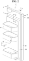
- Fig. 2 is a rear perspective view of the first storage area door 21 according to an embodiment
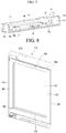
- Fig. 3 is an exploded perspective view of the first storage space door 21 of Fig. 2
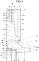
- Fig. 4 is a cross-sectional view taken of the upper portion of the first storage space door 21 along line 4-4 of Fig. 2 .
- a rear surface of the first storage area door 21 disposed at the right side is illustrated.
- the first storage area door 21 includes a door frame 300 defining an outer appearance thereof, a panel assembly 100 coupled to the door frame 300, and a door liner 200 defining an insulating space 410, in which the insulator 400 is disposed, together with the door frame 300 and the panel assembly 100.
- the door frame 300 may be provided or assembled in the shape of a rectangular frame having an opening, and the panel assembly 100 or the door liner 200 may cover the opening of the door frame 300.
- the door liner 200 may include a liner opening 201.
- the panel assembly 100 may cover the liner opening 201.
- the panel assembly 100 may include a front panel 110.
- the front panel 110 may define an outer appearance of a front surface of the first storage area door 21.
- the front panel 110 may be made of a glass material and/or a transparent plastic material.
- the front panel 110 may include a first portion 111 and a second portion 112 disposed outside the first portion 111.
- the second portion 112 is disposed to at least partly or fully surround the first portion 111.
- a printed layer may be disposed along a circumference of an edge of a rear surface of the front panel 110, and the first portion 111 and the second portion 112 may be distinguished from each other by the printed layer.
- the printed layer may be referred to as a bezel. That is, a portion of the front panel 110 at which the printed layer is provided may be defined as the second portion 112.
- the first portion 111 may be a portion through which light irradiated from a lighting unit 250 may be transmitted.
- the printed layer may restrict or block the light transmission through the second portion 112. So, the second portion 112 is opaque or non transparent.
- the panel assembly 100 may further include one or more insulating panels 120 and 130 disposed behind the front panel 110.
- insulating panels are illustrated to be disposed behind the front panel 110, but the invention also works with only one insulating panel disposed behind the front panel 110.
- the one or more insulating panels may include the first insulating panel 120 and the second insulating panel 130.
- the first insulating panel 120 may be disposed behind the front panel 110, and the second insulating panel 130 may be disposed between the front panel 110 and the first insulating panel 120.
- a spacer 140 may be provided between the front panel 110 and the second insulating panel 130, and an insulating space is provided between the front panel 110 and the second insulating panel 130.
- An insulating gas may be injected into the insulating space, or the insulating space may be in a vacuum state to define a vacuum insulating space.
- a further spacer 140 may be provided between the second insulating panel 130 and the first insulating panel 120, and an insulating space is provided between the second insulating panel 130 and the first insulating panel 120.
- An insulating gas may be injected into the insulating space, or the insulating space may be in a vacuum state to define a vacuum insulating space.
- Each of the insulating panels 120 and 130 may be made of a glass material and/or a transparent plastic material.
- the spacer 140 may be disposed to face the second portion 112 so that the spacer 140 is not exposed to the outside. Thus, a user cannot see the one or more spacer 140.
- the one or more insulating panels 120 and 130 may be larger in size than the first portion 111 of the front panel 110.
- a left and right width and a height of the front panel 110 may be greater than a left and right width and a height of the respective insulating panels 120 and 130.
- the spacer 140 may be disposed at a position that is spaced a predetermined distance inward from an outer end of the front panel 110. That is, the spacer 140 may be disposed between a boundary line 113 between the first portion 111 and the second portion 112 and the outer end of the front panel 110.
- the first storage area door 21 may further include a heater frame 390 attached to the rear surface of the front panel 110, preferably by an adhesion portion.
- the heater frame 390 may be provided in form of a rectangular frame, be disposed behind the front panel 110, and be disposed between the front panel 110 and the one or more first or second insulating panel 120, 130 outside the spacer 140 to surround the spacer 140. That is, the spacer 140 may be disposed in a region defined by the heater frame 390.
- a groove 392 for accommodating a heater 394 may be defined in a front surface of the heater frame 390.
- the heater 394 may be provided therein and may provide heat to the front panel 110 to prevent water droplets from being generated on the front panel 110.
- the heater frame 390 may be attached to a rear surface of the second portion 112 of the front panel 110 so that the heater frame 390 is not exposed to the outside.
- the door frame 300 may be provided by a single frame or by an assembling a plurality of frames.
- the door frame 300 may be fixed to the rear surface of the front panel 110, preferably by an adhesion portion 330.
- the adhesion portion 330 may be, for example, an adhesive or a double-sided tape.
- the adhesion portion 330 may be disposed on the rear surface of the second portion 112 of the front panel 110 so that the adhesion portion 330 is not exposed to the outside.
- the door frame 300 may cover a circumferential surface (including a top surface, a bottom surface, and both side surfaces) of the front panel 110.
- the door frame 300 may include an upper frame 310 (or a first frame).
- the upper frame 310 may define an outer appearance of an upper portion of the first storage area door 21.
- the door frame 300 may further include a lower frame 340 (or a second frame) spaced apart from the upper frame 310.
- the door frame 300 may further include a pair of side frames 350 and 360 connecting the upper frame 310 to the lower frame 340.
- the upper frame 310 may have an accommodation space 310a in which various components such as an electric wire are disposed, and the accommodation space 310a may be covered by the frame cover 320.
- Each of the side frames 350 and 360 may include a side surface portion 352 that is in contact with side surfaces of the upper frame 310 and the lower frame 340 and a front surface portion 354, which extends from the side surface portion 352 in a direction crossing the side surface portion 352 and is in contact with a front wall 311 of the upper frame 310 and a front wall 342 of the lower frame 340.
- the front surface portion 354 may extend from the side surface portion 352 at a position spaced a predetermined distance backward from a front end of the side surface portion 352.
- a front surface of the front surface portion 354 may adhere to a rear surface of the front panel 110 by the adhesion portion.
- a rear surface of the front surface portion 354 may be in contact with front surfaces of the upper frame 310 and the lower frame 340 and be coupled to the upper frame 310 and the lower frame 340 by a coupling member such as, for example, a screw.
- a slot 362 providing a space in which a hinge 26 is disposed may be provided in any one of the pair of side frames 350 and 360.
- the door liner 200 may include an inner body 202 defining the liner opening 201.
- the inner body 202 may include an upper body, a lower body, and a pair of side bodies.
- a coupling protrusion 207 may be provided on each of the side bodies of the inner body 202 for the coupling of a basket 50.
- the coupling protrusion 207 may be provided on each of the side bodies 205.
- a plurality of coupling protrusions 207 may be disposed to be spaced apart from each other in the vertical direction.
- a protrusion groove 52 that receives the coupling protrusion 207 may be defined in each of both side walls of the basket 50.
- the coupling protrusion 207 may be accommodated in the protrusion groove 52 so that the basket 50 is supported by the protrusion groove 52.
- the basket 50 In a state in which the basket 50 is mounted on the door liner 200, at least a portion of the basket 50 may be disposed to face the first portion 111 of the front panel 110. Thus, when the lighting unit 250 operates, the basket 50 and the foods accommodated in the basket 50 may be visible from the outside by the light passing through the first part 111.
- An end 202a of the inner body 202 may be in contact with the panel assembly 100.
- the end 202a of the inner body 202 may be in contact with the rear surface of the first insulating panel 120.
- the end 202a of the inner body 202 may be in contact with a position spaced a predetermined distance inward from the outer end the first insulating panel 120.
- the door liner 200 may further include an outer body 210 and a connection body 209 connecting the outer body 210 to the inner body 202.
- the door liner 200 may include a gasket coupling portion 211 to which the gasket 450 is coupled.
- the gasket coupling portion 211 may be provided in a recessed shape, and the outer body 210 and the connection body 209 may provide the gasket coupling portion 211.
- the gasket coupling portion 211 may extend in a closed loop shape.
- the lighting unit 250 may be installed on the door liner 200.
- the lighting unit 250 may be installed on the inner body 202.
- a portion of the lighting unit 250 may be disposed to face the opening 201.
- the door liner 200 may further include a liner extension portion 212 that is bent around the outer body 210 to extend and is in contact with the door frame 300.
- the liner extension portion 212 may extend from the outer body 210 in a direction crossing the outer body 210.
- the liner extension portion 212 may be in contact with a frame extension portion 319 provided on the rear wall 312 of the upper frame 310 and the rear wall 344 (see Fig. 13 ) of the lower frame 340.
- the liner extension portion 212 and the frame extension portion 319 may adhere to each other by the adhesion portion.
- the adhesion portion may be provided on a portion or the whole of the contact portions between the liner extension portion 212 and the door frame 300.
- the liner extension portion 212 and the frame extension portion 319 may be in contact with each other without the adhesion portion.
- the two members are in contact with each other even when the two members are coupled to each other in a state in which the adhesion portion is disposed between the two members.
- the liner extension portion 212 may be in contact with a rear side of each of the side frames 350 and 360.
- the insulating space 410, in which the insulator 400 is disposed may be defined by the door frame 300, the panel assembly 100, and the door liner 200.
- the door frame 300 may include an injection portion for injecting the foaming liquid.
- the injection portion will be described later with reference to the drawings.
- the insulator 400 may be disposed in the insulating space 410.
- the foaming liquid is combined with a structure that is in contact with the foaming liquid. That is, the foaming liquid not only serves for insulation, but also serves as a connection portion that connects two spaced structures to each other.
- a portion of the insulator 400 may be disposed to surround the insulating panels 120 and 130 in the panel assembly 100, and in particular may be in contact with a rear surface of the first insulating panel 120.
- a portion of the insulator 400 that is in contact with the rear surface of the first insulating panel 120 is in contact with the inner body 202 of the door liner 200.
- the insulator 400 serves to connect the door liner 200 to the panel assembly 100.
- the other portion of the insulator 400 is in contact with the frame extension portion 319 the upper frame 310 and the outer body 210 of the door liner 200.
- the insulator 400 connects the door liner 200 to the upper frame 310.
- a rib 214 extending upwardly to the upper side of the door may be provided on a top surface of the outer body 210.
- the rib 214 is disposed to be spaced apart from the liner extension portion 212.
- the rib 214 may be disposed to be spaced apart from the liner extension portion 212 in a forward direction toward the front panel 110.
- a space, in which the frame extension portion 319 disposed is defined in a gap between the rib 214 and the liner extension portion 212.
- the frame extension portion 319 is seated on the outer body 210 between the rib 214 and the liner extension portion 212.
- a sensor module 60 may be mounted in the upper portion of the door.
- the sensor module 60 may be mounted on the upper frame 310.
- the sensor module 60 may sense an knock input.
- the sensed knock input is an effective knock input, i.e. a known knock pattern
- the lighting unit 250 may operate while the first storage area door 21 is closed.
- the sensor module 60 may include a sensor element 620 and a sensor PCB 610 on which the sensor element 620 is installed.
- the sensor element 620 may be, for example, an acceleration sensor.
- vibration is generated in the front panel 110 by the knock, and the vibration generated in the front panel 110 is transmitted to the acceleration sensor through the front wall 311 of the upper frame 310 and the sensor PCB 610.
- the lighting unit 250 may operate.
- the upper frame 310 may include the front wall 311 and a rear wall 312 disposed to face the front wall 311.
- a vertical length of the front wall 311 is less than that of the rear wall 312.
- a lower end of the front wall 311 may be disposed higher than a lower end of the rear wall 312.
- a lower side of the front wall 311 and a lower side of the rear wall 312 may be connected to each other by a connection wall 315.
- the front wall 311 may include a protrusion rib 311a that protrudes forward, and the protrusion rib 311a may be attached to a rear surface of the front panel 110 by the adhesion portion 330. That is, the front wall 311 may be connected to the rear surface of the front panel 110.
- a plurality of protrusion ribs 311a may be disposed to be spaced apart from each other in the vertical direction, and each of the protrusion ribs 311a may extend lengthily in the horizontal direction.
- the sensor module 60 may be installed on the front wall 311 in the upper frame 310. When the sensor module 60 is installed on the front wall 311, the sensor module 60 may face the protrusion rib 311a.
- Fig. 5 is a perspective view of the upper frame when viewed downward from a front side of the upper frame according to an embodiment
- Fig. 6 is a perspective view of the upper frame when viewed downward from a rear side of the upper frame according to an embodiment
- Fig. 7 is a perspective view of the upper frame when viewed from an upper side of the upper frame according to an embodiment.
- the upper frame 310 may include a front wall 311 and a rear wall 312, a pair of side walls 313a and 313b connecting the front wall 311 to the rear wall 312, and a connection wall 315 connecting a lower portion of the front wall 311, a lower portion of the rear wall 312, and lower portions of the pair of side walls 313a and 313b to each other.
- the upper portion of the upper frame 310 includes an opening 310b.
- the walls 311, 312, 313a, 313b, and 315 of the upper frame 310 define an accommodation space 310a.
- the accommodation space 310a is partitioned from the insulating space 410.
- the sensor module 60 may be accommodated in the accommodation space 310a through the opening 310b.
- a hinge accommodation portion 314a having a shape that is recessed so that the hinge 26 is disposed may be defined in the rear wall 312 of the upper frame 310, and a guide 314 through which a shaft (not shown) provided on the hinge 26 passes may be provided below the hinge accommodation portion 314a.
- the upper frame 310 may include a coupling boss 318 coupled to the frame cover 320.
- a coupling member may pass through the frame cover 320 from an upper side of the frame cover 320 and then be coupled to the coupling boss 318.
- connection wall 315 may be bent one or more times.
- the connection wall 315 may include a first wall 315a extending from the front wall 311 toward the rear wall 312, a second wall 315b extending to be inclined downward from the first wall 315a toward the rear wall 312, and a third wall connecting the second wall 315a to the rear wall 312.
- a portion of the front wall 311 may be spaced apart from the rear surface of the front panel 110 so that the insulator 400 is disposed between the front wall 311 and the rear surface of the front panel 110. That is, a portion of the front wall 311 may be in contact with the insulator 400.
- connection wall 315 may also be in contact with the insulator 400.
- each of the first to third walls 315a, 315b, and 315c may be in contact with the insulator 400.
- the upper frame 310 may include one or more injection portions 316 and 317 for injecting the foaming liquid.
- the upper frame 310 may include the plurality of injection portions 316 and 317 so that the foaming liquid is uniformly distributed in the insulating space 410.
- the plurality of injection portions 316 and 317 may include a first injection portion 316 and a second injection portion 317, which are spaced apart from each other in a horizontal direction.
- first and second injection portions 316 and 317 may be disposed to be spaced apart from each other in a left and right direction in the upper frame 310.
- the first injection portion 316 and the second injection portion 317 may be disposed between the first side wall 313a and the second side wall 313b.
- the first injection portion 316 may be disposed close to the first side wall 313a
- the second injection portion 317 may be disposed close to the second side wall 313b.
- the second side wall 313b is disposed close to the hinge accommodation portion 314a.
- the first injection portion 316 and the second injection portion 317 serve to guide the foaming liquid, which is injected through a foaming liquid injection nozzle (not shown) disposed above the upper frame 310, to a lower side of the upper frame in the process of injecting the foaming liquid.
- the first injection portion 316 may include a first guide tube 316a disposed in the accommodation space 310a and a first guide groove 316c disposed below the first guide tube 316a.
- the first guide tube 316a and the first guide groove 316c provide a passage through which the foaming liquid flows.
- the first guide tube 316a may be spaced apart from the front wall 311, the pair of side walls 313, and the rear wall 312.
- the first guide tube 316a may include a first inlet 316b.
- the first guide tube 316a may extend in the vertical direction within the accommodation space 310a.
- the first guide tube 316a may extend upward from the connection wall 315.
- the first guide tube 316a is disposed in the accommodation space 310a defined by the upper frame 310, and the first guide groove 316c is disposed outside the upper frame 310.
- the first guide tube 316a may guide the foaming liquid from the outside of the insulating space 410 to the insulating space 410, and the first guide groove 316c may continuously guide the foaming liquid (the foaming liquid passing through the first guide tube 316a) discharged from the upper frame 310 downward in the insulating space 410.
- the outside of the insulating space 410 is substantially the inner space of the upper frame 310.
- the foaming liquid in the first guide tube 316a, the foaming liquid may be guided to flow in a first direction, and in the first guide groove 316c, at least a portion of the foaming liquid may be guided to additionally flow in the first direction in the insulating space 410.
- the first guide groove 316c may be defined.
- connection wall 315 may include a first surface defining the accommodation space 310a and a second surface defining the insulating space 410.
- the first guide tube 316a may extend from the first surface, and the first guide groove 316c may be defined by recessing the second surface.
- the first guide groove 316c may be recessed from the second surface toward the rear wall 312.
- the first guide groove 316c may extend vertically from the connection wall 315.
- the first guide groove 316c may be defined in the second wall 315b and the third wall 315c.
- the first guide tube 316a may extend from the first wall 315a.
- the first guide groove 316c may include a first outlet 316d.
- the first outlet 316d may be disposed on the third wall 315c.
- a horizontal cross-section of the first guide tube 316a may have a circular shape, and a horizontal cross-section of the first guide groove 316c may have a semicircular shape or a shape similar to the semicircular shape. That is, a cross-sectional area of the first guide tube 316a in a second direction perpendicular to the first direction is greater than a cross-sectional area of the first guide groove 316c.
- the second injection portion 317 may have substantially the same shape as the first injection portion 316.
- the second injection portion 317 may be disposed at a position avoiding the hinge accommodation portion 314a.
- the first injection portion 316 and the second injection portion 317 may be disposed between the hinge accommodation portion 314a and the first side wall 313a.
- the second injection portion 317 may include a second guide tube 317a disposed in the space 310a and a second guide groove 317c disposed below the second guide tube 317a.
- a distance between a reference line and the second guide tube 317a may be less than a distance between the reference line and the first guide tube 316a based on the reference line that bisects the upper frame 310 in the left and right direction.
- Each of the second guide tube 317a and the second guide groove 317c provides a passage through which the foaming liquid flows.
- the second guide tube 317a may be spaced apart from the front wall 311, the pair of side walls 313, and the rear wall 312.
- the second guide tube 317a may include a second inlet 317b.
- the second guide tube 317a may extend in the vertical direction in the accommodation space 310a.
- the second guide tube 317a may extend upward from the connection wall 315.
- the second guide tube 317a may be disposed inside the upper frame 310, and the second guide groove 317c may be disposed outside the upper frame 310.
- the second guide tube 317a may guide the foaming liquid from the outside of the insulating space 410 to the insulating space 410, and the second guide groove 317c may continuously guide the foaming liquid discharged from the upper frame 310 downward in the insulating space 410.
- the foaming liquid in the second guide tube 317a, the foaming liquid may be guided to flow in a first direction, and in the second guide groove 317c, the foaming liquid may be guided to additionally flow in the first direction in the insulating space 410.
- connection wall 315 As a portion of the connection wall 315 is recessed toward the rear wall 312, the second guide groove 317c may be defined.
- the second guide groove 317c may extend vertically from the connection wall 315.
- the second guide groove 317c may be defined in the second wall 315b and the third wall 315c.
- the second guide tube 317a may extend from the first surface of the connection wall 315, and the second guide groove 317c may be defined by recessing the second surface of the connection wall 315.
- the second guide groove 317c may be recessed toward the rear wall 312 from the second surface.
- the second guide groove 317c includes a first outlet 317d.
- the first outlet 317d may be disposed on the third wall 315c.
- a horizontal cross-section of the second guide tube 317 may have a circular shape, and a horizontal cross-section of the second guide groove 317a may have a semicircular shape. That is, a cross-sectional area of the second guide tube 317a in a second direction perpendicular to the first direction is greater than a cross-sectional area of the second guide groove 317c.
- Fig. 8 is a view illustrating a state in which the first storage area door 21 without the door liner 200 assembled
- Fig. 9 is a cross-sectional view taken along line 9-9 of Fig. 2
- Fig. 10 is a cross-sectional view taken along line 10-10 of Fig. 2
- Fig. 11 is a perspective view illustrating an arrangement of the first injection portion and the door liner.
- the insulating space 410 may include first to fourth spaces 411, 412, 413, and 414.
- the first space 411 may be a space defined by one side surface of each of the insulating panel 120 and 130 and the first side frame 350.
- the first space 411 may extend in the vertical direction.
- the first outlet 316d of the first injection portion 316 may be disposed to face the first space 411.
- the first outlet 316d of the first injection portion 316 may be disposed above the first space 411.
- the second space 412 may be a space defined by the other side surface of each of the insulating panels 120 and 130 and the second side frame 360.
- the second space 412 may extend in the vertical direction.
- the third space 413 may be a space defined by a bottom surface of each of the insulating panels 120 and 130 and the lower frame 340. Also, the third space 413 may be a space defined by each of the side frames 350 and 360 and the lower frame 340.
- the third space 413 may allow the first space 411 and the second space 412 to communicate with each other.
- the fourth space 414 may be a space defined by a top surface of each of the insulating panels 120 and 130 and the upper frame 310.
- the fourth space 414 may allow the first space 411 and the second space 412 to communicate with each other.
- the first guide groove 316c and the second guide groove 317c are disposed in the insulating space. That is, according to this embodiment, the outlets 316d and 317d of the injection portions 316 and 317 are disposed in the insulating space 410.
- the outlets 316d and 317d of the injection portions 316 and 317 are disposed in the insulating space 410, straightness of the injected foaming liquid may be improved. That is, even in a state in which the foaming liquid is introduced into the insulating space 410, the foaming liquid may straightly flow to the outlets 316d and 317d by the first guide grooves 316c and 317c. For example, the straightness of the foaming liquid in the vertical direction may be improved.
- the first storage area door 21 is provided to be longer in the vertical direction than the left and right width, and each of the first space 411 and the second space 412 extending in the vertical direction has a narrow horizontal cross-section due to the presence of the panel assembly 100. If the foaming liquid is not quickly filled in the insulating space 410, there is a limitation in that the foaming liquid may be hardened before being filled in the insulating space 410 as a whole.
- the foaming liquid may be quickly and uniformly distributed in the insulating space 410, and thus, the foaming liquid may be filled in the insulating space 410 as a whole.
- a portion of the first outlet 316d of the first injection portion 316 may be disposed to face the door liner 200, and the other portion may be disposed to face the first space 411.
- a portion of the foaming liquid injected through the first injection portion 316 may move directly to the first space 411 (see an arrow A), and the other portion may collide with the door liner 200 to move to the fourth space 414 (see an arrow B).
- an amount of foaming liquid flowing into the first space 411 is greater than that of the foaming liquid flowing into the fourth space 414.
- the second outlet 317d of the second injection portion 317 may be disposed to face the door liner 200.
- the second outlet 317d of the second injection portion 317 may be disposed to face the gasket coupling portion 211.
- a portion of the second inlet 317b may be disposed to face at least one insulating panel, and the other portion may be disposed to face the door liner 200.
- the foaming liquid injected through the second injection portion 317 collides with the at least one insulating panel or the door liner 200.
- a portion of the foaming liquid may move to the second space 412 (see an arrow C), and the other portion may be filled in the fourth space 414 (see an arrow D).
- the foaming liquid injected through the first injection portion 316 and the second injection portion 317 flows into the third space 413 through the first space 411 and the second space 412 so as to be filled first into the third space 413 and then and then filled into the first space 411 and the second space 412.
- the foaming liquid is filled in the first space 411 and the second space 412, the foaming liquid is filled in the fourth space 414.
- the supply of the foaming liquid may be finished.
- a portion of the insulator 400 may be filled in the guide grooves 316c and 317c.
- the foaming liquid may be disposed in the guide tubes 316a and 317a to prevent the foaming liquid from overflowing to the outside of the upper frame 310.
- a sensor module 60 within the accommodation space 310a may be prevented from being in contact with the foaming liquid or the insulator within the guide tubes 316a and 317a.
- the sensor module 60 is accessible through the opening 310b of the upper frame 310 even after the formation of the insulator 400 is completed, service of the sensor module 60 is possible.
- each of the injection portions 316 and 317 may be covered by the frame cover 320 when the frame cover 320 is coupled to the upper frame 310.
- an upper end of each of the guide tubes 316a and 317a may be in contact with the bottom surface of the frame cover 320.
- Fig. 12 is a cross-sectional view taken along line 12-12 of Fig. 2 .
- the lighting unit 250 may be installed on the door liner 200.
- the lighting unit 250 may be installed on the inner body 202.
- the lighting unit 250 may include a case 251 and a cover 252 that covers the case 251.
- the cover 252 may extend lengthily in the left and right direction along the door liner 200 and may be installed on the inner body 202. A portion of the cover 252 may be in contact with the first insulating panel 120. That is, in the state in which the cover 252 is installed on the inner body 202, the cover 252 and a portion of the inner body 202 may be in contact with the first insulating panel 120.
- the case 251 defines a space for accommodating a light emitting unit PCB 254 in which a plurality of light emitting units 256 are installed.
- the case 251 includes a reflective surface 253 on which a surface facing the light emitting unit PCB 254 is rounded or inclined. The light irradiated from the light emitting unit 256 is reflected by the reflective surface 253 and is directed to the cover 252.
- the cover 252 may be provided to be transparent or translucent so that the light reflected from the reflective surface 253 and then spread may be transmitted.
- the light emitting unit 256 irradiates light in a direction away from the first insulating panel 120, and the irradiated light is reflected from the reflective surface 253 to passes through the cover 252 and then is transmitted toward a linear opening 201 of the door liner 200.
- FIG. 13 is a cross-sectional view taken along line 13-13 of Fig. 2 .
- the door liner 200 may include air holes 230 and 232 through which air present in the insulating space 410 is discharged when the foaming liquid is injected into the insulating space 410.
- the air holes 230 and 232 may include a first air hole 230 for discharging the air of the fourth space 414 to the outside.
- a plurality of first air holes 230 may be defined to be spaced apart in the horizontal direction.
- the gasket coupling portion 211 may extend along a circumference of the door liner 200, and a portion of the gasket coupling portion 211 may be disposed higher than the lighting unit 250. A portion of the gasket coupling portion 211 disposed higher than the lighting unit 250 may be referred to as a first coupling portion 211a.
- the first air hole 230 may be disposed lower than the first coupling portion 211a at a position close to the first coupling portion 211a. That is, the first air hole 230 may be disposed radially inside the gasket coupling portion 211. In another aspect, the first air hole 230 may be disposed inside an area defined by the gasket coupling portion 211.
- the plurality of first air holes 230 may be covered by the gasket.
- the plurality of first air holes 230 may be prevented from being exposed to the outside.
- the first air hole 230 may have a cross-sectional area that gradually decreases in a direction away from the insulating space 410.
- the first air hole 230 may include an inlet 230a through which the air of the insulating space 410 is introduced and an outlet 230b through which the air is discharged to the outside.
- the inlet 230a may have a size less than that of the outlet 230b.
- the foaming liquid may be prevented from being introduced.
- the air holes 230 and 232 may include a second air hole 232 for discharging the air of the third space 413 to the outside.
- a plurality of second air holes 232 may be disposed to be spaced apart in the horizontal direction.
- the other portion of the gasket coupling portion 211 may be disposed adjacent to the lower frame 340.
- the other portion of the gasket coupling portion 211 disposed adjacent to the lower frame 340 may be referred to as a second coupling portion 211b.
- the second air hole 232 may be disposed higher than the second coupling portion 211b at a position close to the second coupling portion 211b. That is, the second air hole 232 may be disposed radially inside the gasket coupling portion 211. In another aspect, the second air hole 232 may be disposed inside an area defined by the gasket coupling portion 211.
- the plurality of second air holes 232 may be covered by the gasket.
- the plurality of second air holes 232 may be prevented from being exposed to the outside.
- the second air hole 232 may have a cross-sectional area that gradually decreases in a direction away from the insulating space 410.
- the second air hole 232 may include an inlet 232a through which the air of the insulating space 410 is introduced and an outlet 232b through which the air is discharged to the outside.
- the inlet 232a may have a size less than that of the outlet 232b.
- the foaming liquid may be prevented from being introduced.
- Fig. 14 is a view illustrating an inner body of the door liner according to an embodiment
- Fig. 15 is a cross-sectional view taken along line 15-15 of Fig. 2
- Fig. 16 is a view illustrating a state in which the insulator is disposed in a recessed space of the door liner.
- an inner body 202 of the door liner 200 includes a first body 203 and a second body 204 extending from a first body 203.
- the coupling protrusion 207 may be disposed on the first body 203.
- An installation opening 206 for installing the lighting unit 250 may be provided on the first body 203 and the second body 204.
- the installation opening 206 may be defined by being recessed from the second body 204 toward the first body 203.
- the second body 204 may be in contact with the rear surface 120a of the first insulating panel 120.
- the lighting unit 250 in the state in which the lighting unit 250 is disposed in the installation opening 206, the lighting unit 250 may be in contact with the rear surface 120a of the first insulating panel 120.
- the second body 204 may have a thickness greater than that of the first body 202.
- the second body 204 may increase in thickness as a distance from the first body 202 increases.
- a portion of the second body 204, which is connected to the first body 202 may have a thickness greater than that of a portion of the second body 204, which is in contact with the first insulating panel 120.
- the second body 204 may include an inner surface 204b defining the insulating space 410 and an outer surface 204c facing the inner surface 204b.
- the outer surface 204c may define the liner opening 201.
- the inner surface 204b may be in contact with the insulator 400 in the insulating space 410.
- a distance between the outer surface 204c and the inner surface 204b may increase as approaching the first insulating panel 120.
- a distance between the outer surface 204c and the inner surface 204b at the portion of the second body 204, which is connected to the first body 202 may be greater than that between the outer surface 204c and the inner surface 204b at the portion of the second body 204, which is in contact with the first insulating panel 120.
- the outer surface 204c may be continued from the first body 203 to define a straight line.
- the user may see the outer surface 204c from the inner body 202. Since the outer surface 204c of the second body 204 defines a continuous surface with the first body 203, there is no height difference on the inner body 202, and thus, the inner body 202 is simple and elegant.
- the outer surface 204c of the second body 204 defines the continuous surface with the first body 203, a size of the second portion 112 in the front panel 110 may be reduced. As a result, the size of the first portion 111 serving as the transmission portion may increase.
- the outer surface 204b is continued from the first body 202, but may extend to be inclined at a predetermined angle from the first body 202.
- the second body 204 may include a contact surface 204d that is in contact with the rear surface 120a of the first insulating panel 120.
- the contact surface 204d may be in contact with the rear surface 120a of the first insulating panel 120 at a position spaced a predetermined distance inward from an edge 120b of the first insulating panel 120.
- the contact surface 204d may be disposed to face the second portion 112 of the front panel 110.
- An angle ⁇ 1 defined between the inner surface 204b and the rear surface 120a of the first insulating panel 120 in the state in which the contact surface 204d is in contact with the rear surface 120a of the first insulating panel 120 may be less than about 90 degrees.
- the angle between the inner surface 204b and the contact surface 204d may be an obtuse angle.
- An angle between the contact surface 204d and the outer surface 204c may be an acute angle.
- the angle between the contact surface 204d and the inner surface 204b may be greater than that between the contact surface 204d and the outer surface 204c.
- a recessed space 204a may be defined in the contact surface 204d.
- the recessed space 204a may be recessed from the contact surface 204b in a direction away from the first insulating panel 120.
- the recessed space 204a may be recessed from the contact surface 204b toward the first body 203.
- the recessed space 204a may be continued along the contact surface 204d in the inner body 202.
- the leaking foaming liquid may be accommodated in the recessed space 204a.
- the insulator disposed in the recessed space 204a serves as a barrier that prevents the foaming solution from additionally leaking.
- the portion 400a of the insulator 400 disposed in the recessed space 204a may prevent the foaming liquid from leaking between the contact surface 204d and the rear surface 120a of the first thermal insulating panel 120.
- the foaming liquid may be prevented from leaking from the recessed space 204a to the outer surface 204c by the rapid curing of the foaming liquid.
- the hardened foaming liquid serves to connect the second body 204 to the rear surface 120a of the first insulating panel 120.
- coupling force between the door liner 200 and the first insulating panel 120 may increase.
- the recessed space 204a may be disposed closer to the inner surface 204b than the outer surface 204c.
- a width W1 of a portion between the recessed space 204a and the inner surface 204b is greater than a width W2 of a portion between the recessed space 204a and the outer surface 204b.
- a distance between the recessed space 204a and the inner surface 204b may be less than a distance between the recessed space 204a and the outer surface 204b.
- the foaming liquid leaking from the inner surface 204b toward the depressed space 204a may quickly move to the recessed space 204a and then hardened.
- the foaming liquid of the recessed space 204a may be effectively prevented from leaking toward the outer surface 204b.
- a minimum thickness of the second body 204 may be greater than a depth D of the recessed space 204a.
- a maximum width of the recessed space 204a may be less than a minimum distance between the recessed space 204a and the outer surface 204c.
- the depth D of the recessed space 204a may be greater than a maximum width of the recessed space 204a.
- the foaming liquid leaking into the recessed space 204a may be prevented from leaking to the outside before being hardened in the recessed space 204a.
- the straightness of the foaming liquid is maintained in the insulating space, and thus the foaming liquid may be uniformly distributed inside the refrigerator door.
- the injection portion may be prevented that the injection portion from being blocked in the process of injecting the foaming liquid.
- the space inside the upper frame may be partitioned from the injection portion, and thus, the service of the components inside the upper frame may be easy.
- the foaming liquid may be prevented from leaking in the state in which injection of the foaming liquid is completed.
- the foaming liquid When the foaming liquid moves to the recessed space of the door liner, the foaming liquid may connect the door liner to the insulating panel to increase in coupling force between the door liner and the insulating panel.
Abstract
Provided is a refrigerator. The refrigerator includes a cabinet having a storage space and a door configured to open and close the storage space. The door includes a panel assembly including a front panel and an insulating panel spaced apart from the front panel, a door frame that is in contact with the front panel, and a door liner which is connected to the door frame and is in contact with the insulating panel, the door liner being configured to define an insulating space, in which an insulator is disposed, together with the panel assembly and the door frame. The door liner includes a contact surface that is in contact with the insulating panel, and a recessed space is defined on the contact surface.
Description
- This specification relates to a refrigerator.
- In general, refrigerators are home appliances for storing foods at low temperature in an inner storage space covered by a refrigerator door. Here, the inside of the storage space is cooled using cool air that is generated by being heat-exchanged with a refrigerant circulated in a refrigeration cycle to store the foods in an optimal state.
- Since the storage space is sealed by the refrigerator door, the refrigerator door has to have an insulating function.
- To allow the refrigerator door to have the insulating function, the refrigerator door may define an insulating space therein, and a foaming liquid injected through an injection hole is hardened to provide an insulator in the insulating space.
- A door for a home appliance is disclosed in
Korean Patent Publication No. 10-2017-0019341 (Published on February 21, 2017 - The door may include a panel assembly and a frame assembly which has an opening and to which an edge of the panel assembly is connected to support panel assembly, and a foaming space is defined between the frame assembly and the panel assembly to accommodate an insulator.
- A plurality of foam injection holes into which the insulator is injected are provided in a top or bottom surface of the frame assembly.
- However, according to the prior art document, the foam injection holes are defined in the top or bottom surface of the frame assembly, and the foaming liquid passing through the foam injection holes are directly introduced into the foaming space.
- However, a portion of the foaming liquid that is directly introduced into the foaming space, but another of the foaming liquid is spread to the surroundings, and the other portion is hardened by colliding with surrounding structures.
- Here, the hardened foaming liquid may act as resistance around the foam injection holes since it collides with the surrounding structures and may thereby reduce an injection rate of the foaming liquid. Finally, the foaming liquid may not be uniformly distributed into the foaming space.
- Also, the foaming liquid spread to the surroundings may act as resistance of the foaming liquid that is to be subsequently injected.
- The frame assembly includes a rear frame disposed on a rear surface of the door and a side frame connected to the rear frame to define the foaming space. The panel assembly include a front panel, an intermediate panel, and a rear panel.
- A first end of the rear frame is in contact with the rear panel, and the side frame is in contact with the front panel to define the foaming space.
- The foaming liquid is injected into the space, and while the foaming liquid is hardened, the foaming liquid is expanded. However, according to the prior art document, there is a limitation that the foaming liquid leaks between the first end of the rear frame and the rear panel.
- It is an object of the present invention to provide a refrigerator in which a foaming liquid is prevented from leaking in a state in which the foaming liquid is completely injected.
- Optionally or additionally, it is an object of the present invention to also provide a refrigerator in which coupling force between a door liner and an insulating panel increases.
- Optionally or additionally, it is an object of the present invention to also provide a refrigerator in which a transmission portion, through which light is capable of being transmitted, is maximized in size.
- Optionally or additionally, it is an object of the present invention to also provide a refrigerator in which a foaming liquid is maintained in straightness even in an insulating space so as to be uniformly distributed into a refrigerator door.
- Optionally or additionally, it is an object of the present invention to also provide a refrigerator in which an injection portion is prevented from being blocked while a foaming liquid is injected.
- Optionally or additionally, it is an object of the present invention to also provide a refrigerator in which an inner space of an upper frame is partitioned from a foam injection portion to facilitate a service of components within the upper frame.
- The object is solved by the features of the independent claims. Preferred embodiments are given in the dependent claims.
- In one embodiment, a refrigerator includes: a cabinet having a storage space; and a door configured to open and close the storage space.
- The door may include: a panel assembly including a front panel and an insulating panel spaced apart from the front panel; a door frame that is in contact with the front panel; and a door liner which is connected to the door frame and is in contact with the insulating panel, the door liner being configured to define an insulating space, in which an insulator is disposed, together with the panel assembly and the door frame.
- The door liner may include a contact surface that is in contact with the insulating panel.
- A recessed space may be defined on the contact surface.
- The recessed space may be recessed from the contact surface in a direction that is away from the insulating panel.
- The recessed space may be continuous along the contact surface.
- The door liner may include an inner body configured to define a liner opening that is covered by the insulating panel.
- The inner body may be in contact with the contact surface.
- The inner body may include: a first body; and a second body extending from the first body and having the contact surface and the recessed space.
- A portion of the second body, on which the contact surface is disposed, may have a thickness greater than that of a portion of the second body, on which the contact surface is disposed.
- The second body may include: an outer surface configured to define the liner opening; and an inner surface configured to define the insulating space.
- The contact surface may be configured to connect the outer surface to the inner surface.
- The outer surface and the first body may be configured to define a continuous surface so as to define a straight line.
- An angle defined by the contact surface and the outer surface may be greater than that defined by the contact surface and the inner surface.
- An angle defined by the contact surface and the outer surface may be an acute angle, and an angle defined by the inner surface and the contact surface may be an obtuse angle.
- The recessed space may be disposed closer to the inner surface than the outer surface.
- In the second body, a portion of the second body between the recessed space and the inner surface may have a width less than that of a portion of the second body between the recessed space and the outer surface.
- The recessed space may have a depth less than a minimum thickness of the second body. The recessed space may have a depth less than a maximum width of the recessed space.
- The maximum width of the recessed space may be less than a minimum distance between the recessed space and the outer surface.
- A distance between the inner surface and the outer surface may gradually increase from the first body toward the insulating panel.
- A distance from the recessed space to the inner surface may be less than that from the recessed space to the outer surface.
- The recessed space may have a depth greater than the distance from the recessed space to the inner surface.
- In another embodiment, a refrigerator includes: a cabinet having a storage space; and a door configured to open and close the storage space.
- The door may include: a panel assembly including a front panel and an insulating panel spaced apart from the front panel; a door frame connected to the panel assembly; and a door liner configured to define an insulating space, in which an insulator is disposed, together with the panel assembly and the door frame.
- The door frame may include an injection portion through which a foaming liquid for forming the insulator is injected.
- A portion of the injection portion may be configured to guide the foaming liquid from the outside of the insulating space to the insulating space, and the other portion of the injection portion may be configured to guide the foaming liquid so that the foaming liquid flows in the insulating space.
- The panel assembly may include: a front panel; and an insulating panel spaced apart from the front panel.
- A portion of the injection portion may include a guide tube through which the foaming liquid passes through the door frame, and the other portion of the injection portion may include a guide groove configured to guide the foaming liquid passing through the guide tube.
- The guide tube may be configured to guide the foaming liquid so that the foaming liquid flows into the insulating space in a first direction, and the guide groove may be configured to guide the foaming liquid so that at least a portion of the foaming liquid in the insulating space additionally flows in the first direction.
- A cross-sectional area of the guide tube in a second direction perpendicular to the first direction may be greater than that of the guide groove.
- The door frame may include a first frame connected to a rear surface of the front panel. The first frame may include the injection portion. The first frame may define an outer appearance of an upper portion of the door.
- The first frame may include a front wall disposed to face the front panel; a rear wall spaced apart from the front wall; and a connection wall configured to connect a lower portion of the front wall to a lower portion of the rear wall, the connection wall being configured to define an accommodation space together with the front wall and the rear wall.
- The connection wall may be configured to connect a lower portion of the front wall to a lower portion of the rear wall.
- The guide tube may extend from the connection wall to the accommodation space, and the guide groove may be defined by recessing a portion of the connection wall.
- The connection wall may include: a first surface configured to define the accommodation space; and a second surface configured to define the insulating space. The guide tube may extend from the first surface. The guide groove may be defined by recessing the second surface toward the rear wall.
- The connection wall may include: a first wall extending from a lower end of the front wall toward the rear wall; a second wall extending to be inclined downward from the first wall toward the rear wall; and a third wall configured to connect the second wall to the rear wall.
- The guide tube may extend from the first wall to the accommodation space. The guide groove may be defined in the second wall and the third wall.
- An upper portion of the door frame may include an opening, the opening may be covered by a frame cover coupled to the door frame, and when the frame cover may be coupled to the door frame, the frame cover is configured to cover the guide tube.
- A bottom surface of the frame cover may be seated on an end of the guide tube. A sensor module may be mounted in an accommodation space of the first frame. The sensor module may be configured to sense a knock applied to the front panel.
- The injection portion may include a first injection portion and a second injection portion, which are spaced apart from each other in a horizontal direction.
- The first frame may include: a first side wall and a second side wall, which are spaced apart from each other; and a hinge accommodation part having a recessed shape defined in the first side wall. The first injection portion and the second injection portion may be disposed between the hinge accommodation portion and the second side wall.
- The door liner may include: a gasket coupling portion having a recessed shape to be coupled to the gasket and extending in a closed loop shape; and an air hole defined in the closed loop region, in which the gasket coupling portion is disposed, configured to discharge air within the insulating space.
- The air hole may include: an inlet through which air of the insulating space is introduced; and an outlet through which air is discharged to the outside. The outlet may have a diameter less than that of the inlet.
- When the gasket is coupled to the gasket coupling portion, the gasket may be configured to cover the air hole.
- The door liner may include a contact surface that is in contact with the insulating panel, and a recessed space may be defined in the contact surface.
- The recessed space may be recessed from the contact surface in a direction that is away from the insulating panel.
- The recessed space may be continuous along the contact surface.
- The door liner may include an inner body configured to define a liner opening that is covered by the panel assembly. The inner body may be in contact with the contact surface.
- The inner body may include: a first body; and a second body extending from the first body and having the contact surface and the recessed space.
- A portion of the second body, on which the contact surface is disposed, may have a thickness greater than that of a portion of the second body, on which the contact surface is disposed.
- The second body may include: an outer surface configured to define the liner opening; an inner surface configured to define the insulating space; and the contact surface configured to connect the outer surface to the inner surface.
- The outer surface and the first body may be configured to define a continuous surface so as to define a straight line.
- An angle defined by the contact surface and the outer surface may be greater than that defined by the contact surface and the inner surface.
- An angle defined by the contact surface and the outer surface may be an acute angle. An angle defined by the inner surface and the contact surface may be an obtuse angle.
- The recessed space may be disposed closer to inner surface than the outer surface.
- The recessed space may have a depth less than a minimum thickness of the second body. The recessed space may have a depth greater than a maximum width of the recessed space. The maximum width of the recessed space may be less than a minimum distance between the recessed space and the outer surface.
- A distance between the inner surface and the outer surface may gradually increase from the first body toward the insulating panel.
- The details of one or more embodiments are set forth in the accompanying drawings and the description below. Other features will be apparent from the description and drawings, and from the claims.
-
-
Fig. 1 is a perspective view illustrating a refrigerator according to an embodiment. -
Fig. 2 is a rear perspective view of a first storage area door according to an embodiment. -
Fig. 3 is an explode perspective view of the first storage area door ofFig. 2 . -
Fig. 4 is a cross-sectional view taken along line 4-4 ofFig. 2 . -
Fig.5 view of upper frame downward from front side of the upper frame of an embodiment. -
Fig. 6 is a perspective view of the upper frame when viewed downward from a rear side of the upper frame of an embodiment. -
Fig. 7 is a perspective view of the upper frame when viewed from an upper side of the upper frame of an embodiment. -
Fig. 8 is a state in which the first storage area door except for the door liner is assembled. -
Fig. 9 is a cross-sectional view taken along line 9-9 ofFig. 2 . -
Fig. 10 is a cross-sectional view taken along line 10-10 ofFig. 2 . -
Fig. 11 is a perspective view illustrating an arrangement of a first injection portion and the door liner. -
Fig. 12 is a cross-sectional view taken along line 12-12 ofFig. 2 . -
Fig. 13 is a cross-sectional view taken along line 13-13 ofFig. 2 . -
Fig. 14 is a view illustrating an inner body of the door liner according to an embodiment. -
Fig. 15 is a cross-sectional view taken along line 15-15 ofFig. 2 . -
Fig. 16 is a view illustrating a state in which an insulator is disposed in a recessed space of the door liner. - Hereinafter, some embodiments of the present disclosure will be described in detail with reference to the accompanying drawings. It should be noted that when components in the drawings are designated by reference numerals, the same components have the same reference numerals as far as possible even though the components are illustrated in different drawings. Further, in description of embodiments of the present disclosure, when it is determined that detailed descriptions of well-known configurations or functions disturb understanding of the embodiments of the present disclosure, the detailed descriptions will be omitted.
- Also, in the description of the embodiments of the present disclosure, the terms such as first, second, A, B, (a) and (b) may be used. Each of the terms is merely used to distinguish the corresponding component from other components, and does not delimit an essence, an order or a sequence of the corresponding component. It should be understood that when one component is "connected", "coupled" or "joined" to another component, the former may be directly connected or jointed to the latter or may be "connected", coupled" or "joined" to the latter with a third component interposed therebetween.
-
Fig. 1 is a perspective view illustrating a refrigerator according to an embodiment. - Referring to
Fig. 1 , arefrigerator 1 according to this embodiment may include acabinet 10 defining a storage space and arefrigerator door 20 for opening and closing the storage space. - The storage space may include one or more storage areas, wherein the one or more storage areas may be arranged in a vertical direction or in left and right direction side by side to each other.
- There may be one or
more refrigerator doors 20. The number ofrefrigerator doors 20 may vary according to the number of storage areas. For example, when the plurality of storage areas are arranged in the vertical direction, the firststorage area doors 21 and 22 may open and close the upper first storage area, and the secondstorage area doors - In this case, one storage area may be opened and closed by one door or a plurality of doors in a rotating or sliding (drawer type) manner.
- In
Fig. 1 , for example, the upper first storage area is opened and closed by rotating the firststorage area doors 21 and 22 arranged in the left and right directions. The rotation is allowed by hinges 26. At least one of thehinges 26 may be at least partially covered by ahinge cover 28. In particular the hinge provided at the upper portion of the door may be covered by thehinge cover 28 - The first
storage area doors 21 and 22 may include a left door and a right door. -
Fig. 2 is a rear perspective view of the firststorage area door 21 according to an embodiment,Fig. 3 is an exploded perspective view of the firststorage space door 21 ofFig. 2 , andFig. 4 is a cross-sectional view taken of the upper portion of the firststorage space door 21 along line 4-4 ofFig. 2 . - In
Fig. 2 , for example, a rear surface of the firststorage area door 21 disposed at the right side is illustrated. - Hereinafter, the right first
storage area door 21 will be described with reference toFigs.2-4 . - The first
storage area door 21 includes adoor frame 300 defining an outer appearance thereof, apanel assembly 100 coupled to thedoor frame 300, and adoor liner 200 defining an insulatingspace 410, in which theinsulator 400 is disposed, together with thedoor frame 300 and thepanel assembly 100. - The
door frame 300 may be provided or assembled in the shape of a rectangular frame having an opening, and thepanel assembly 100 or thedoor liner 200 may cover the opening of thedoor frame 300. - The
door liner 200 may include aliner opening 201. Thepanel assembly 100 may cover theliner opening 201. - The
panel assembly 100 may include afront panel 110. Thefront panel 110 may define an outer appearance of a front surface of the firststorage area door 21. - The
front panel 110 may be made of a glass material and/or a transparent plastic material. - The
front panel 110 may include afirst portion 111 and asecond portion 112 disposed outside thefirst portion 111. Thesecond portion 112 is disposed to at least partly or fully surround thefirst portion 111. - A printed layer may be disposed along a circumference of an edge of a rear surface of the
front panel 110, and thefirst portion 111 and thesecond portion 112 may be distinguished from each other by the printed layer. The printed layer may be referred to as a bezel. That is, a portion of thefront panel 110 at which the printed layer is provided may be defined as thesecond portion 112. - The
first portion 111 may be a portion through which light irradiated from alighting unit 250 may be transmitted. The printed layer may restrict or block the light transmission through thesecond portion 112. So, thesecond portion 112 is opaque or non transparent. - The
panel assembly 100 may further include one or moreinsulating panels front panel 110. - In
Fig. 4 , for example, two insulating panels are illustrated to be disposed behind thefront panel 110, but the invention also works with only one insulating panel disposed behind thefront panel 110. - The one or more insulating panels may include the first
insulating panel 120 and the secondinsulating panel 130. - The first
insulating panel 120 may be disposed behind thefront panel 110, and the secondinsulating panel 130 may be disposed between thefront panel 110 and the firstinsulating panel 120. - A
spacer 140 may be provided between thefront panel 110 and the secondinsulating panel 130, and an insulating space is provided between thefront panel 110 and the secondinsulating panel 130. An insulating gas may be injected into the insulating space, or the insulating space may be in a vacuum state to define a vacuum insulating space. - A
further spacer 140 may be provided between the secondinsulating panel 130 and the firstinsulating panel 120, and an insulating space is provided between the secondinsulating panel 130 and the firstinsulating panel 120. An insulating gas may be injected into the insulating space, or the insulating space may be in a vacuum state to define a vacuum insulating space. - Each of the insulating
panels - The
spacer 140 may be disposed to face thesecond portion 112 so that thespacer 140 is not exposed to the outside. Thus, a user cannot see the one or more spacer 140. The one or moreinsulating panels first portion 111 of thefront panel 110. - A left and right width and a height of the
front panel 110 may be greater than a left and right width and a height of the respective insulatingpanels - Thus, the
spacer 140 may be disposed at a position that is spaced a predetermined distance inward from an outer end of thefront panel 110. That is, thespacer 140 may be disposed between aboundary line 113 between thefirst portion 111 and thesecond portion 112 and the outer end of thefront panel 110. - The first
storage area door 21 may further include aheater frame 390 attached to the rear surface of thefront panel 110, preferably by an adhesion portion. Theheater frame 390 may be provided in form of a rectangular frame, be disposed behind thefront panel 110, and be disposed between thefront panel 110 and the one or more first or secondinsulating panel spacer 140 to surround thespacer 140. That is, thespacer 140 may be disposed in a region defined by theheater frame 390. - A
groove 392 for accommodating aheater 394 may be defined in a front surface of theheater frame 390. Theheater 394 may be provided therein and may provide heat to thefront panel 110 to prevent water droplets from being generated on thefront panel 110. Theheater frame 390 may be attached to a rear surface of thesecond portion 112 of thefront panel 110 so that theheater frame 390 is not exposed to the outside. - The
door frame 300 may be provided by a single frame or by an assembling a plurality of frames. - The
door frame 300 may be fixed to the rear surface of thefront panel 110, preferably by anadhesion portion 330. Theadhesion portion 330 may be, for example, an adhesive or a double-sided tape. - The
adhesion portion 330 may be disposed on the rear surface of thesecond portion 112 of thefront panel 110 so that theadhesion portion 330 is not exposed to the outside. - In the state in which the
door frame 300 is attached to thefront panel 110, thedoor frame 300 may cover a circumferential surface (including a top surface, a bottom surface, and both side surfaces) of thefront panel 110. - The
door frame 300 may include an upper frame 310 (or a first frame). Theupper frame 310 may define an outer appearance of an upper portion of the firststorage area door 21. - The
door frame 300 may further include a lower frame 340 (or a second frame) spaced apart from theupper frame 310. Thedoor frame 300 may further include a pair of side frames 350 and 360 connecting theupper frame 310 to thelower frame 340. - The
upper frame 310 may have anaccommodation space 310a in which various components such as an electric wire are disposed, and theaccommodation space 310a may be covered by theframe cover 320. - Each of the side frames 350 and 360 may include a
side surface portion 352 that is in contact with side surfaces of theupper frame 310 and thelower frame 340 and afront surface portion 354, which extends from theside surface portion 352 in a direction crossing theside surface portion 352 and is in contact with afront wall 311 of theupper frame 310 and afront wall 342 of thelower frame 340. - The
front surface portion 354 may extend from theside surface portion 352 at a position spaced a predetermined distance backward from a front end of theside surface portion 352. - A front surface of the
front surface portion 354 may adhere to a rear surface of thefront panel 110 by the adhesion portion. - A rear surface of the
front surface portion 354 may be in contact with front surfaces of theupper frame 310 and thelower frame 340 and be coupled to theupper frame 310 and thelower frame 340 by a coupling member such as, for example, a screw. - A
slot 362 providing a space in which ahinge 26 is disposed may be provided in any one of the pair of side frames 350 and 360. - The
door liner 200 may include aninner body 202 defining theliner opening 201. Theinner body 202 may include an upper body, a lower body, and a pair of side bodies. - A
coupling protrusion 207 may be provided on each of the side bodies of theinner body 202 for the coupling of abasket 50. For example, thecoupling protrusion 207 may be provided on each of theside bodies 205. In each of the side bodies, a plurality ofcoupling protrusions 207 may be disposed to be spaced apart from each other in the vertical direction. Aprotrusion groove 52 that receives thecoupling protrusion 207 may be defined in each of both side walls of thebasket 50. - Thus, when the
basket 50 moves downward in a state in which thebasket 50 is disposed in theliner opening 201 of theinner body 202, thecoupling protrusion 207 may be accommodated in theprotrusion groove 52 so that thebasket 50 is supported by theprotrusion groove 52. - In a state in which the
basket 50 is mounted on thedoor liner 200, at least a portion of thebasket 50 may be disposed to face thefirst portion 111 of thefront panel 110. Thus, when thelighting unit 250 operates, thebasket 50 and the foods accommodated in thebasket 50 may be visible from the outside by the light passing through thefirst part 111. - An
end 202a of theinner body 202 may be in contact with thepanel assembly 100. For example, theend 202a of theinner body 202 may be in contact with the rear surface of the firstinsulating panel 120. - Here, the
end 202a of theinner body 202 may be in contact with a position spaced a predetermined distance inward from the outer end the firstinsulating panel 120. - The
door liner 200 may further include anouter body 210 and aconnection body 209 connecting theouter body 210 to theinner body 202. - The
door liner 200 may include agasket coupling portion 211 to which thegasket 450 is coupled. Thegasket coupling portion 211 may be provided in a recessed shape, and theouter body 210 and theconnection body 209 may provide thegasket coupling portion 211. Thegasket coupling portion 211 may extend in a closed loop shape. - The
lighting unit 250 may be installed on thedoor liner 200. For example, thelighting unit 250 may be installed on theinner body 202. A portion of thelighting unit 250 may be disposed to face theopening 201. - The
door liner 200 may further include aliner extension portion 212 that is bent around theouter body 210 to extend and is in contact with thedoor frame 300. Theliner extension portion 212 may extend from theouter body 210 in a direction crossing theouter body 210. - The
liner extension portion 212 may be in contact with aframe extension portion 319 provided on therear wall 312 of theupper frame 310 and the rear wall 344 (seeFig. 13 ) of thelower frame 340. - The
liner extension portion 212 and theframe extension portion 319 may adhere to each other by the adhesion portion. In this case, the adhesion portion may be provided on a portion or the whole of the contact portions between theliner extension portion 212 and thedoor frame 300. Alternatively, theliner extension portion 212 and theframe extension portion 319 may be in contact with each other without the adhesion portion. - In this embodiment, it will be defined and described that the two members are in contact with each other even when the two members are coupled to each other in a state in which the adhesion portion is disposed between the two members.
- Also, the
liner extension portion 212 may be in contact with a rear side of each of the side frames 350 and 360. - The insulating
space 410, in which theinsulator 400 is disposed may be defined by thedoor frame 300, thepanel assembly 100, and thedoor liner 200. - The
door frame 300 may include an injection portion for injecting the foaming liquid. The injection portion will be described later with reference to the drawings. - As the foaming liquid is injected through the injection portion, and the foaming liquid is hardened, the
insulator 400 may be disposed in the insulatingspace 410. - In the process of curing the foaming liquid, the foaming liquid is combined with a structure that is in contact with the foaming liquid. That is, the foaming liquid not only serves for insulation, but also serves as a connection portion that connects two spaced structures to each other.
- For example, a portion of the
insulator 400 may be disposed to surround the insulatingpanels panel assembly 100, and in particular may be in contact with a rear surface of the firstinsulating panel 120. - A portion of the
insulator 400 that is in contact with the rear surface of the firstinsulating panel 120 is in contact with theinner body 202 of thedoor liner 200. Thus, theinsulator 400 serves to connect thedoor liner 200 to thepanel assembly 100. - Also, the other portion of the
insulator 400 is in contact with theframe extension portion 319 theupper frame 310 and theouter body 210 of thedoor liner 200. Thus, theinsulator 400 connects thedoor liner 200 to theupper frame 310. - A
rib 214 extending upwardly to the upper side of the door may be provided on a top surface of theouter body 210. Therib 214 is disposed to be spaced apart from theliner extension portion 212. - For example, the
rib 214 may be disposed to be spaced apart from theliner extension portion 212 in a forward direction toward thefront panel 110. A space, in which theframe extension portion 319 disposed is defined in a gap between therib 214 and theliner extension portion 212. - Thus, the
frame extension portion 319 is seated on theouter body 210 between therib 214 and theliner extension portion 212. - A
sensor module 60 may be mounted in the upper portion of the door. In particular thesensor module 60 may be mounted on theupper frame 310. Thesensor module 60 may sense an knock input. When the sensed knock input is an effective knock input, i.e. a known knock pattern, thelighting unit 250 may operate while the firststorage area door 21 is closed. - The
sensor module 60 may include asensor element 620 and asensor PCB 610 on which thesensor element 620 is installed. - The
sensor element 620 may be, for example, an acceleration sensor. When a knock is applied to the front surface of thefront panel 110, vibration is generated in thefront panel 110 by the knock, and the vibration generated in thefront panel 110 is transmitted to the acceleration sensor through thefront wall 311 of theupper frame 310 and thesensor PCB 610. - When an intensity of the vibration generated by knocking two or more times within a predetermined time is equal to or greater than a reference intensity, it is determined as an effective knock input, and in this case, the
lighting unit 250 may operate. - The
upper frame 310 may include thefront wall 311 and arear wall 312 disposed to face thefront wall 311. - A vertical length of the
front wall 311 is less than that of therear wall 312. A lower end of thefront wall 311 may be disposed higher than a lower end of therear wall 312. A lower side of thefront wall 311 and a lower side of therear wall 312 may be connected to each other by aconnection wall 315. - The
front wall 311 may include aprotrusion rib 311a that protrudes forward, and theprotrusion rib 311a may be attached to a rear surface of thefront panel 110 by theadhesion portion 330. That is, thefront wall 311 may be connected to the rear surface of thefront panel 110. - Here, a plurality of
protrusion ribs 311a may be disposed to be spaced apart from each other in the vertical direction, and each of theprotrusion ribs 311a may extend lengthily in the horizontal direction. - The
sensor module 60 may be installed on thefront wall 311 in theupper frame 310. When thesensor module 60 is installed on thefront wall 311, thesensor module 60 may face theprotrusion rib 311a. -
Fig. 5 is a perspective view of the upper frame when viewed downward from a front side of the upper frame according to an embodiment, andFig. 6 is a perspective view of the upper frame when viewed downward from a rear side of the upper frame according to an embodiment.Fig. 7 is a perspective view of the upper frame when viewed from an upper side of the upper frame according to an embodiment. - Referring to
Figs. 4 to 7 , theupper frame 310 may include afront wall 311 and arear wall 312, a pair ofside walls front wall 311 to therear wall 312, and aconnection wall 315 connecting a lower portion of thefront wall 311, a lower portion of therear wall 312, and lower portions of the pair ofside walls - Thus, the upper portion of the
upper frame 310 includes anopening 310b. Thewalls upper frame 310 define anaccommodation space 310a. Theaccommodation space 310a is partitioned from the insulatingspace 410. - Thus, the
sensor module 60 may be accommodated in theaccommodation space 310a through theopening 310b. - A
hinge accommodation portion 314a having a shape that is recessed so that thehinge 26 is disposed may be defined in therear wall 312 of theupper frame 310, and aguide 314 through which a shaft (not shown) provided on thehinge 26 passes may be provided below thehinge accommodation portion 314a. - The
upper frame 310 may include acoupling boss 318 coupled to theframe cover 320. In a state in which a portion of theframe cover 320 is seated on a top surface of thecoupling boss 318, a coupling member may pass through theframe cover 320 from an upper side of theframe cover 320 and then be coupled to thecoupling boss 318. - The
connection wall 315 may be bent one or more times. For example, theconnection wall 315 may include afirst wall 315a extending from thefront wall 311 toward therear wall 312, asecond wall 315b extending to be inclined downward from thefirst wall 315a toward therear wall 312, and a third wall connecting thesecond wall 315a to therear wall 312. - A portion of the
front wall 311 may be spaced apart from the rear surface of thefront panel 110 so that theinsulator 400 is disposed between thefront wall 311 and the rear surface of thefront panel 110. That is, a portion of thefront wall 311 may be in contact with theinsulator 400. - The
connection wall 315 may also be in contact with theinsulator 400. For example, each of the first tothird walls insulator 400. - The
upper frame 310 may include one ormore injection portions - The
upper frame 310 may include the plurality ofinjection portions space 410. - The plurality of
injection portions first injection portion 316 and asecond injection portion 317, which are spaced apart from each other in a horizontal direction. - For example, the first and
second injection portions upper frame 310. - The
first injection portion 316 and thesecond injection portion 317 may be disposed between thefirst side wall 313a and thesecond side wall 313b. Here, thefirst injection portion 316 may be disposed close to thefirst side wall 313a, and thesecond injection portion 317 may be disposed close to thesecond side wall 313b. Thesecond side wall 313b is disposed close to thehinge accommodation portion 314a. - The
first injection portion 316 and thesecond injection portion 317 serve to guide the foaming liquid, which is injected through a foaming liquid injection nozzle (not shown) disposed above theupper frame 310, to a lower side of the upper frame in the process of injecting the foaming liquid. - The
first injection portion 316 may include afirst guide tube 316a disposed in theaccommodation space 310a and afirst guide groove 316c disposed below thefirst guide tube 316a. - The
first guide tube 316a and thefirst guide groove 316c provide a passage through which the foaming liquid flows. - The
first guide tube 316a may be spaced apart from thefront wall 311, the pair of side walls 313, and therear wall 312. - The
first guide tube 316a may include afirst inlet 316b. Thefirst guide tube 316a may extend in the vertical direction within theaccommodation space 310a. For example, thefirst guide tube 316a may extend upward from theconnection wall 315. - The
first guide tube 316a is disposed in theaccommodation space 310a defined by theupper frame 310, and thefirst guide groove 316c is disposed outside theupper frame 310. - The
first guide tube 316a may guide the foaming liquid from the outside of the insulatingspace 410 to the insulatingspace 410, and thefirst guide groove 316c may continuously guide the foaming liquid (the foaming liquid passing through thefirst guide tube 316a) discharged from theupper frame 310 downward in the insulatingspace 410. The outside of the insulatingspace 410 is substantially the inner space of theupper frame 310. - For example, in the
first guide tube 316a, the foaming liquid may be guided to flow in a first direction, and in thefirst guide groove 316c, at least a portion of the foaming liquid may be guided to additionally flow in the first direction in the insulatingspace 410. - As a portion of the
connection wall 315 is recessed toward therear wall 312, thefirst guide groove 316c may be defined. - For example, the
connection wall 315 may include a first surface defining theaccommodation space 310a and a second surface defining the insulatingspace 410. - The
first guide tube 316a may extend from the first surface, and thefirst guide groove 316c may be defined by recessing the second surface. For example, thefirst guide groove 316c may be recessed from the second surface toward therear wall 312. - The
first guide groove 316c may extend vertically from theconnection wall 315. Thefirst guide groove 316c may be defined in thesecond wall 315b and thethird wall 315c. Thefirst guide tube 316a may extend from thefirst wall 315a. - The
first guide groove 316c may include afirst outlet 316d. Thefirst outlet 316d may be disposed on thethird wall 315c. - A horizontal cross-section of the
first guide tube 316a may have a circular shape, and a horizontal cross-section of thefirst guide groove 316c may have a semicircular shape or a shape similar to the semicircular shape. That is, a cross-sectional area of thefirst guide tube 316a in a second direction perpendicular to the first direction is greater than a cross-sectional area of thefirst guide groove 316c. - The
second injection portion 317 may have substantially the same shape as thefirst injection portion 316. Thesecond injection portion 317 may be disposed at a position avoiding thehinge accommodation portion 314a. For example, thefirst injection portion 316 and thesecond injection portion 317 may be disposed between thehinge accommodation portion 314a and thefirst side wall 313a. - The
second injection portion 317 may include asecond guide tube 317a disposed in thespace 310a and asecond guide groove 317c disposed below thesecond guide tube 317a. A distance between a reference line and thesecond guide tube 317a may be less than a distance between the reference line and thefirst guide tube 316a based on the reference line that bisects theupper frame 310 in the left and right direction. - Each of the
second guide tube 317a and thesecond guide groove 317c provides a passage through which the foaming liquid flows. - The
second guide tube 317a may be spaced apart from thefront wall 311, the pair of side walls 313, and therear wall 312. - The
second guide tube 317a may include asecond inlet 317b. Thesecond guide tube 317a may extend in the vertical direction in theaccommodation space 310a. Thesecond guide tube 317a may extend upward from theconnection wall 315. - The
second guide tube 317a may be disposed inside theupper frame 310, and thesecond guide groove 317c may be disposed outside theupper frame 310. - The
second guide tube 317a may guide the foaming liquid from the outside of the insulatingspace 410 to the insulatingspace 410, and thesecond guide groove 317c may continuously guide the foaming liquid discharged from theupper frame 310 downward in the insulatingspace 410. - For example, in the
second guide tube 317a, the foaming liquid may be guided to flow in a first direction, and in thesecond guide groove 317c, the foaming liquid may be guided to additionally flow in the first direction in the insulatingspace 410. - As a portion of the
connection wall 315 is recessed toward therear wall 312, thesecond guide groove 317c may be defined. - The
second guide groove 317c may extend vertically from theconnection wall 315. Thesecond guide groove 317c may be defined in thesecond wall 315b and thethird wall 315c. - The
second guide tube 317a may extend from the first surface of theconnection wall 315, and thesecond guide groove 317c may be defined by recessing the second surface of theconnection wall 315. For example, thesecond guide groove 317c may be recessed toward therear wall 312 from the second surface. - The
second guide groove 317c includes afirst outlet 317d. Thefirst outlet 317d may be disposed on thethird wall 315c. - A horizontal cross-section of the
second guide tube 317 may have a circular shape, and a horizontal cross-section of thesecond guide groove 317a may have a semicircular shape. That is, a cross-sectional area of thesecond guide tube 317a in a second direction perpendicular to the first direction is greater than a cross-sectional area of thesecond guide groove 317c. -
Fig. 8 is a view illustrating a state in which the firststorage area door 21 without thedoor liner 200 assembled,Fig. 9 is a cross-sectional view taken along line 9-9 ofFig. 2 ,Fig. 10 is a cross-sectional view taken along line 10-10 ofFig. 2 , andFig. 11 is a perspective view illustrating an arrangement of the first injection portion and the door liner. - Referring to
Figs. 8 to 11 , in a state in which the firststorage area door 21 except for thedoor liner 200 is assembled, the insulatingspace 410 may include first tofourth spaces - The
first space 411 may be a space defined by one side surface of each of the insulatingpanel first side frame 350. Thefirst space 411 may extend in the vertical direction. - The
first outlet 316d of thefirst injection portion 316 may be disposed to face thefirst space 411. Thefirst outlet 316d of thefirst injection portion 316 may be disposed above thefirst space 411. - The
second space 412 may be a space defined by the other side surface of each of the insulatingpanels second side frame 360. Thesecond space 412 may extend in the vertical direction. - The
third space 413 may be a space defined by a bottom surface of each of the insulatingpanels lower frame 340. Also, thethird space 413 may be a space defined by each of the side frames 350 and 360 and thelower frame 340. - The
third space 413 may allow thefirst space 411 and thesecond space 412 to communicate with each other. - The
fourth space 414 may be a space defined by a top surface of each of the insulatingpanels upper frame 310. Thefourth space 414 may allow thefirst space 411 and thesecond space 412 to communicate with each other. - In a state in which the
door liner 200 is assembled, thefirst guide groove 316c and thesecond guide groove 317c are disposed in the insulating space. That is, according to this embodiment, theoutlets injection portions space 410. - According to this embodiment, when the
outlets injection portions space 410, straightness of the injected foaming liquid may be improved. That is, even in a state in which the foaming liquid is introduced into the insulatingspace 410, the foaming liquid may straightly flow to theoutlets first guide grooves - The first
storage area door 21 is provided to be longer in the vertical direction than the left and right width, and each of thefirst space 411 and thesecond space 412 extending in the vertical direction has a narrow horizontal cross-section due to the presence of thepanel assembly 100. If the foaming liquid is not quickly filled in the insulatingspace 410, there is a limitation in that the foaming liquid may be hardened before being filled in the insulatingspace 410 as a whole. - However, when the straightness of the foaming liquid is strengthened, like this embodiment, the foaming liquid may be quickly and uniformly distributed in the insulating
space 410, and thus, the foaming liquid may be filled in the insulatingspace 410 as a whole. - In the state in which the
door liner 200 is assembled, a portion of thefirst outlet 316d of thefirst injection portion 316 may be disposed to face thedoor liner 200, and the other portion may be disposed to face thefirst space 411. - Thus, a portion of the foaming liquid injected through the
first injection portion 316 may move directly to the first space 411 (see an arrow A), and the other portion may collide with thedoor liner 200 to move to the fourth space 414 (see an arrow B). - Here, an amount of foaming liquid flowing into the
first space 411 is greater than that of the foaming liquid flowing into thefourth space 414. - When the
door liner 200 is assembled, thesecond outlet 317d of thesecond injection portion 317 may be disposed to face thedoor liner 200. For example, thesecond outlet 317d of thesecond injection portion 317 may be disposed to face thegasket coupling portion 211. A portion of thesecond inlet 317b may be disposed to face at least one insulating panel, and the other portion may be disposed to face thedoor liner 200. - Thus, the foaming liquid injected through the
second injection portion 317 collides with the at least one insulating panel or thedoor liner 200. A portion of the foaming liquid may move to the second space 412 (see an arrow C), and the other portion may be filled in the fourth space 414 (see an arrow D). - The foaming liquid injected through the
first injection portion 316 and thesecond injection portion 317 flows into thethird space 413 through thefirst space 411 and thesecond space 412 so as to be filled first into thethird space 413 and then and then filled into thefirst space 411 and thesecond space 412. - After the foaming liquid is filled in the
first space 411 and thesecond space 412, the foaming liquid is filled in thefourth space 414. - After the
fourth space 414 is filled with the foaming liquid, the supply of the foaming liquid may be finished. - When curing of the foaming liquid is completed in the state in which the foaming liquid is filled in the
fourth space 414, a portion of theinsulator 400 may be filled in theguide grooves - Even if the foaming liquid overflows from the
fourth space 414 when the supply of the foaming liquid is finished, since theinjection portions guide tubes guide tubes upper frame 310. - Also, even if the foaming liquid is filled in the
guide tubes guide tubes accommodation space 310a of theupper frame 310, asensor module 60 within theaccommodation space 310a may be prevented from being in contact with the foaming liquid or the insulator within theguide tubes - Thus, since the
sensor module 60 is accessible through theopening 310b of theupper frame 310 even after the formation of theinsulator 400 is completed, service of thesensor module 60 is possible. - The
inlets injection portions frame cover 320 when theframe cover 320 is coupled to theupper frame 310. Although not limited, an upper end of each of theguide tubes frame cover 320. -
Fig. 12 is a cross-sectional view taken along line 12-12 ofFig. 2 . - Referring to
Fig. 12 , thelighting unit 250 may be installed on thedoor liner 200. For example, thelighting unit 250 may be installed on theinner body 202. - For example, the
lighting unit 250 may include acase 251 and acover 252 that covers thecase 251. - The
cover 252 may extend lengthily in the left and right direction along thedoor liner 200 and may be installed on theinner body 202. A portion of thecover 252 may be in contact with the firstinsulating panel 120. That is, in the state in which thecover 252 is installed on theinner body 202, thecover 252 and a portion of theinner body 202 may be in contact with the firstinsulating panel 120. - The
case 251 defines a space for accommodating a light emittingunit PCB 254 in which a plurality of light emittingunits 256 are installed. - The
case 251 includes areflective surface 253 on which a surface facing the light emittingunit PCB 254 is rounded or inclined. The light irradiated from thelight emitting unit 256 is reflected by thereflective surface 253 and is directed to thecover 252. - The
cover 252 may be provided to be transparent or translucent so that the light reflected from thereflective surface 253 and then spread may be transmitted. - For example, the
light emitting unit 256 irradiates light in a direction away from the firstinsulating panel 120, and the irradiated light is reflected from thereflective surface 253 to passes through thecover 252 and then is transmitted toward alinear opening 201 of thedoor liner 200. -
FIG. 13 is a cross-sectional view taken along line 13-13 ofFig. 2 . - Referring to
Figs. 9 ,12 and13 , thedoor liner 200 may includeair holes space 410 is discharged when the foaming liquid is injected into the insulatingspace 410. - The air holes 230 and 232 may include a
first air hole 230 for discharging the air of thefourth space 414 to the outside. For example, a plurality offirst air holes 230 may be defined to be spaced apart in the horizontal direction. - The
gasket coupling portion 211 may extend along a circumference of thedoor liner 200, and a portion of thegasket coupling portion 211 may be disposed higher than thelighting unit 250. A portion of thegasket coupling portion 211 disposed higher than thelighting unit 250 may be referred to as afirst coupling portion 211a. - The
first air hole 230 may be disposed lower than thefirst coupling portion 211a at a position close to thefirst coupling portion 211a. That is, thefirst air hole 230 may be disposed radially inside thegasket coupling portion 211. In another aspect, thefirst air hole 230 may be disposed inside an area defined by thegasket coupling portion 211. - When the gasket is coupled to the
gasket coupling portion 211, the plurality offirst air holes 230 may be covered by the gasket. Thus, the plurality offirst air holes 230 may be prevented from being exposed to the outside. - The
first air hole 230 may have a cross-sectional area that gradually decreases in a direction away from the insulatingspace 410. Alternatively, thefirst air hole 230 may include aninlet 230a through which the air of the insulatingspace 410 is introduced and anoutlet 230b through which the air is discharged to the outside. Here, theinlet 230a may have a size less than that of theoutlet 230b. - In this case, while the air may be introduced through the
inlet 230a, the foaming liquid may be prevented from being introduced. - The air holes 230 and 232 may include a
second air hole 232 for discharging the air of thethird space 413 to the outside. For example, a plurality ofsecond air holes 232 may be disposed to be spaced apart in the horizontal direction. - The other portion of the
gasket coupling portion 211 may be disposed adjacent to thelower frame 340. The other portion of thegasket coupling portion 211 disposed adjacent to thelower frame 340 may be referred to as asecond coupling portion 211b. - The
second air hole 232 may be disposed higher than thesecond coupling portion 211b at a position close to thesecond coupling portion 211b. That is, thesecond air hole 232 may be disposed radially inside thegasket coupling portion 211. In another aspect, thesecond air hole 232 may be disposed inside an area defined by thegasket coupling portion 211. - When the gasket is coupled to the
gasket coupling portion 211, the plurality ofsecond air holes 232 may be covered by the gasket. Thus, the plurality ofsecond air holes 232 may be prevented from being exposed to the outside. - The
second air hole 232 may have a cross-sectional area that gradually decreases in a direction away from the insulatingspace 410. Alternatively, thesecond air hole 232 may include aninlet 232a through which the air of the insulatingspace 410 is introduced and anoutlet 232b through which the air is discharged to the outside. Here, theinlet 232a may have a size less than that of theoutlet 232b. - In this case, while the air may be introduced through the
inlet 232a, the foaming liquid may be prevented from being introduced. -
Fig. 14 is a view illustrating an inner body of the door liner according to an embodiment,Fig. 15 is a cross-sectional view taken along line 15-15 ofFig. 2 , andFig. 16 is a view illustrating a state in which the insulator is disposed in a recessed space of the door liner. - Referring to
Figs. 3 ,12 , and14 to 16 , aninner body 202 of thedoor liner 200 according to this embodiment includes afirst body 203 and asecond body 204 extending from afirst body 203. - The
coupling protrusion 207 may be disposed on thefirst body 203. Aninstallation opening 206 for installing thelighting unit 250 may be provided on thefirst body 203 and thesecond body 204. Theinstallation opening 206 may be defined by being recessed from thesecond body 204 toward thefirst body 203. - The
second body 204 may be in contact with therear surface 120a of the firstinsulating panel 120. Here, in the state in which thelighting unit 250 is disposed in theinstallation opening 206, thelighting unit 250 may be in contact with therear surface 120a of the firstinsulating panel 120. - The
second body 204 may have a thickness greater than that of thefirst body 202. - The
second body 204 may increase in thickness as a distance from thefirst body 202 increases. Alternatively, a portion of thesecond body 204, which is connected to thefirst body 202, may have a thickness greater than that of a portion of thesecond body 204, which is in contact with the firstinsulating panel 120. - For example, the
second body 204 may include aninner surface 204b defining the insulatingspace 410 and anouter surface 204c facing theinner surface 204b. - The
outer surface 204c may define theliner opening 201. Theinner surface 204b may be in contact with theinsulator 400 in the insulatingspace 410. - A distance between the
outer surface 204c and theinner surface 204b may increase as approaching the firstinsulating panel 120. Alternatively, a distance between theouter surface 204c and theinner surface 204b at the portion of thesecond body 204, which is connected to thefirst body 202, may be greater than that between theouter surface 204c and theinner surface 204b at the portion of thesecond body 204, which is in contact with the firstinsulating panel 120. - The
outer surface 204c may be continued from thefirst body 203 to define a straight line. - When the first
storage area door 21 is opened, the user may see theouter surface 204c from theinner body 202. Since theouter surface 204c of thesecond body 204 defines a continuous surface with thefirst body 203, there is no height difference on theinner body 202, and thus, theinner body 202 is simple and elegant. - Also, since the
outer surface 204c of thesecond body 204 defines the continuous surface with thefirst body 203, a size of thesecond portion 112 in thefront panel 110 may be reduced. As a result, the size of thefirst portion 111 serving as the transmission portion may increase. - On the other hand, the
outer surface 204b is continued from thefirst body 202, but may extend to be inclined at a predetermined angle from thefirst body 202. - The
second body 204 may include acontact surface 204d that is in contact with therear surface 120a of the firstinsulating panel 120. - The
contact surface 204d may be in contact with therear surface 120a of the firstinsulating panel 120 at a position spaced a predetermined distance inward from anedge 120b of the firstinsulating panel 120. - The
contact surface 204d may be disposed to face thesecond portion 112 of thefront panel 110. - An angle θ1 defined between the
inner surface 204b and therear surface 120a of the firstinsulating panel 120 in the state in which thecontact surface 204d is in contact with therear surface 120a of the firstinsulating panel 120 may be less than about 90 degrees. Thus, the angle between theinner surface 204b and thecontact surface 204d may be an obtuse angle. - An angle between the
contact surface 204d and theouter surface 204c may be an acute angle. - The angle between the
contact surface 204d and theinner surface 204b may be greater than that between thecontact surface 204d and theouter surface 204c. - A recessed
space 204a may be defined in thecontact surface 204d. The recessedspace 204a may be recessed from thecontact surface 204b in a direction away from the firstinsulating panel 120. Alternatively, the recessedspace 204a may be recessed from thecontact surface 204b toward thefirst body 203. - The recessed
space 204a may be continued along thecontact surface 204d in theinner body 202. - Even if a portion of the foaming liquid injected into the
heat insulation space 410 leaks through between thecontact surface 204d and therear surface 120a of the firstinsulating panel 120, the leaking foaming liquid may be accommodated in the recessedspace 204a. - Since a gap between the
contact surface 204d and therear surface 120a of the firstinsulating panel 120 is very small, and a temperature of the foaming liquid is rapidly lowered while the foaming liquid passes through the gap, the foaming liquid is hardened in the recessedspace 204a while moving into the recessedspace 204a. - As illustrated in
Fig. 15 , when the foaming liquid leaking into the recessedspace 204a is hardened, and aportion 400a of theinsulator 400 is disposed in the recessedspace 204a, the insulator disposed in the recessedspace 204a serves as a barrier that prevents the foaming solution from additionally leaking. - That is, the
portion 400a of theinsulator 400 disposed in the recessedspace 204a may prevent the foaming liquid from leaking between thecontact surface 204d and therear surface 120a of the first thermal insulatingpanel 120. - In this embodiment, even if the foaming liquid leaks into the recessed
space 204a, the foaming liquid may be prevented from leaking from the recessedspace 204a to theouter surface 204c by the rapid curing of the foaming liquid. - Also, when the foaming liquid leaking into the recessed
space 204a is hardened, the hardened foaming liquid serves to connect thesecond body 204 to therear surface 120a of the firstinsulating panel 120. Thus, after the foaming is completed, coupling force between thedoor liner 200 and the firstinsulating panel 120 may increase. - The recessed
space 204a may be disposed closer to theinner surface 204b than theouter surface 204c. In thesecond body 204, a width W1 of a portion between the recessedspace 204a and theinner surface 204b is greater than a width W2 of a portion between the recessedspace 204a and theouter surface 204b. A distance between the recessedspace 204a and theinner surface 204b may be less than a distance between the recessedspace 204a and theouter surface 204b. - When the recessed
space 204a is closer to theinner surface 204b than theouter surface 204b, the foaming liquid leaking from theinner surface 204b toward thedepressed space 204a may quickly move to the recessedspace 204a and then hardened. Thus, when the recessedspace 204a is disposed away from theouter surface 204c, the foaming liquid of the recessedspace 204a may be effectively prevented from leaking toward theouter surface 204b. - A minimum thickness of the
second body 204 may be greater than a depth D of the recessedspace 204a. - A maximum width of the recessed
space 204a may be less than a minimum distance between the recessedspace 204a and theouter surface 204c. - The depth D of the recessed
space 204a may be greater than a maximum width of the recessedspace 204a. Thus, the foaming liquid leaking into the recessedspace 204a may be prevented from leaking to the outside before being hardened in the recessedspace 204a. - According to this embodiment, the straightness of the foaming liquid is maintained in the insulating space, and thus the foaming liquid may be uniformly distributed inside the refrigerator door.
- Also, it may be prevented that the injection portion from being blocked in the process of injecting the foaming liquid.
- Also, in the state in which the injection of the foaming liquid is completed, the space inside the upper frame may be partitioned from the injection portion, and thus, the service of the components inside the upper frame may be easy.
- Also, according to this embodiment, the foaming liquid may be prevented from leaking in the state in which injection of the foaming liquid is completed.
- When the foaming liquid moves to the recessed space of the door liner, the foaming liquid may connect the door liner to the insulating panel to increase in coupling force between the door liner and the insulating panel.
- Although embodiments have been described with reference to a number of illustrative embodiments thereof, it should be understood that numerous other modifications and embodiments can be devised by those skilled in the art that will fall within the spirit and scope of the principles of this disclosure. More particularly, various variations and modifications are possible in the component parts and/or arrangements of the subject combination arrangement within the scope of the disclosure, the drawings and the appended claims. In addition to variations and modifications in the component parts and/or arrangements, alternative uses will also be apparent to those skilled in the art.
Claims (15)
- A refrigerator comprising:a cabinet (10) having a storage space; anda door (20) for opening and closing the storage space, wherein the door (20) comprises:a panel assembly (100) comprising a front panel (110) and an insulating panel (120, 130) spaced apart from the front panel (110);a door frame (300) in contact with the front panel (110); anda door liner (200) connected to the door frame (300) and in contact with the insulating panel (120, 130),wherein the door liner (200), the panel assembly (100) and the door frame (300) defining an insulating space (410), in which an insulator (400) is disposed,wherein the door liner (200) comprises a contact surface (204d) in contact with the insulating panel (120, 130), wherein the contact surface (204d) comprises a recessed space (204a).
- The refrigerator of claim 1, wherein the recessed space (204a) is recessed from the contact surface (204d) in a direction away from the insulating panel (120, 130).
- The refrigerator of claim 1 or 2, wherein the recessed space (204a) is continuous along the contact surface (204d).
- The refrigerator of any one of claims 1 to 3, wherein the door liner (200) comprises an inner body (202) configured to define a liner opening (201) that is covered by the insulating panel (120, 130), wherein the insulating panel (120, 130) is in contact with the contact surface (204d).
- The refrigerator of claim 4, wherein the inner body (202) comprises:a first body (203); anda second body (204) extending from the first body (203) and having the contact surface (204d) and the recessed space (204a),wherein a thickness of a portion of the second body (204) is greater than that of the first body (203).
- The refrigerator of claim 5, wherein the second body (204) comprises:an outer surface (204c) configured to define the liner opening (201); andan inner surface (204b) configured to define the insulating space (400),wherein the contact surface (204d) is configured to connect the outer surface (204c) to the inner surface (204b), andthe outer surface (204c) and the first body (203) are configured to define a continuous surface so as to define a straight line.
- The refrigerator of claim 6, wherein an angle defined by the contact surface (204d) and the outer surface (204c) is greater than that defined by the contact surface (204d) and the inner surface (204b).
- The refrigerator of claim 6 or 7, wherein an angle defined by the contact surface (204d) and the outer surface (204c) is an acute angle, and an angle defined by the inner surface (204b) and the contact surface (204d) is an obtuse angle.
- The refrigerator of any one of claims 6 to 8, wherein the recessed space (204a) is disposed closer to the inner surface (204b) than the outer surface (204c).
- The refrigerator of claim any one of claims 6 to 9, wherein, in the second body (204), a width of a portion of the second body (204) between the recessed space (204a) and the inner surface (204b) is less than that of a portion of the second body (204) between the recessed space (204a) and the outer surface (204c).
- The refrigerator of any one of claims 6 to 10, wherein the recessed space (204a) has a depth less than a minimum thickness of the second body (204), or the recessed space (204a) has a depth greater than a maximum width of the recessed space (204a).
- The refrigerator of any one of claims 6 to 11, wherein a maximum width of the recessed space (204a) is less than a minimum distance between the recessed space (204a) and the outer surface (204c).
- The refrigerator of any one of claims 6 to 12, wherein a distance between the inner surface (204b) and the outer surface (204c) gradually increases from the first body (203) toward the insulating panel (120, 130).
- The refrigerator of claim 4, wherein the inner body (202) comprises:an outer surface (204c) configured to define the liner opening (201); andan inner surface (204b) configured to define the insulating space (400),wherein the contact surface (204d) is configured to connect the outer surface (204c) to the inner surface (204b), anda distance from the recessed space (204a) to the inner surface (204b) is less than that from the recessed space (204a) to the outer surface (204c).
- The refrigerator of claim 14, wherein the recessed space (204a) has a depth greater than the distance from the recessed space (204a) to the inner surface(204b).
Applications Claiming Priority (2)
| Application Number | Priority Date | Filing Date | Title |
|---|---|---|---|
| KR1020200082772A KR20220005222A (en) | 2020-07-06 | 2020-07-06 | Refrigerator |
| KR1020200082773A KR20220005223A (en) | 2020-07-06 | 2020-07-06 | Refrigerator |
Publications (1)
| Publication Number | Publication Date |
|---|---|
| EP3936799A1 true EP3936799A1 (en) | 2022-01-12 |
Family
ID=76765054
Family Applications (1)
| Application Number | Title | Priority Date | Filing Date |
|---|---|---|---|
| EP21183731.5A Pending EP3936799A1 (en) | 2020-07-06 | 2021-07-05 | Refrigerator |
Country Status (3)
| Country | Link |
|---|---|
| US (2) | US11885553B2 (en) |
| EP (1) | EP3936799A1 (en) |
| AU (2) | AU2021204714B2 (en) |
Families Citing this family (3)
| Publication number | Priority date | Publication date | Assignee | Title |
|---|---|---|---|---|
| EP3936801A1 (en) * | 2020-07-06 | 2022-01-12 | LG Electronics Inc. | Refrigerator |
| KR20220101524A (en) * | 2021-01-11 | 2022-07-19 | 엘지전자 주식회사 | A door for refrigerator |
| CN217764086U (en) * | 2022-04-29 | 2022-11-08 | 宁波韩电电器有限公司 | Refrigerator door body with perspective window |
Citations (9)
| Publication number | Priority date | Publication date | Assignee | Title |
|---|---|---|---|---|
| JPS4840863U (en) * | 1971-09-18 | 1973-05-24 | ||
| JPS6453886U (en) * | 1987-09-30 | 1989-04-03 | ||
| JPH0473580A (en) * | 1990-07-10 | 1992-03-09 | Matsushita Refrig Co Ltd | Refrigerator door |
| JPH08233443A (en) * | 1995-02-28 | 1996-09-13 | Sanyo Electric Co Ltd | Heat insulating door for refrigerator |
| KR20060036312A (en) * | 2004-10-25 | 2006-04-28 | 엘지전자 주식회사 | Door for refrigerator |
| JP2016173233A (en) * | 2016-07-08 | 2016-09-29 | シャープ株式会社 | Refrigerator |
| KR20170019341A (en) | 2015-07-15 | 2017-02-21 | 엘지전자 주식회사 | A Door for home appliance and home appliance, and Method for manufacturing the same |
| CN107976001A (en) * | 2017-12-26 | 2018-05-01 | 青岛乐克玻璃科技股份有限公司 | Novel energy-saving vacuum glass cold chain door body and preparation method thereof |
| CN108756639A (en) * | 2018-05-14 | 2018-11-06 | 浙江三星新材股份有限公司 | Moisture seal acrylic door body |
Family Cites Families (29)
| Publication number | Priority date | Publication date | Assignee | Title |
|---|---|---|---|---|
| US3411247A (en) * | 1966-10-10 | 1968-11-19 | Amerace Corp | Refrigerator door frame |
| JPS517186B2 (en) | 1971-09-27 | 1976-03-05 | ||
| US4080756A (en) * | 1975-10-09 | 1978-03-28 | Anthony's Manufacturing Company, Inc. | Insulated refrigerator door frame |
| US4891912A (en) * | 1987-07-07 | 1990-01-09 | Ardco, Inc. | Refrigerator door assembly with multiple gasket sealing arrangement |
| US5910083A (en) * | 1990-09-20 | 1999-06-08 | New Anthony, Inc. | Integral spacer for door rail |
| US5636484A (en) * | 1994-08-11 | 1997-06-10 | Odl Incorporated | Hurricane door light |
| US7043886B1 (en) * | 2003-01-07 | 2006-05-16 | Thermoseal Glass Corp. | Refrigerator door assembly |
| DE202005002231U1 (en) * | 2005-01-25 | 2006-06-08 | Liebherr-Hausgeräte Ochsenhausen GmbH | Fridge and / or freezer |
| AU2007276766A1 (en) * | 2006-07-24 | 2008-01-31 | Fortune Resources, Inc. | Decorative door for cooler |
| DE202007007319U1 (en) * | 2007-05-23 | 2007-07-26 | BSH Bosch und Siemens Hausgeräte GmbH | Door structure for household appliance e.g. cooler, has bent bars at transverse edges of door inner panel to engage into exterior opening grooves of closures at transverse edges of door outer panel |
| CN201277781Y (en) * | 2008-09-10 | 2009-07-22 | 海尔集团公司 | Refrigerator |
| KR20150071441A (en) * | 2013-12-18 | 2015-06-26 | 삼성전자주식회사 | Refrigerator |
| US9526353B2 (en) * | 2014-07-22 | 2016-12-27 | Richard Chubb | Door for a freezer cabinet |
| KR20160045545A (en) * | 2014-10-17 | 2016-04-27 | 엘지전자 주식회사 | Refrigerator |
| KR20160095374A (en) * | 2015-02-03 | 2016-08-11 | 엘지전자 주식회사 | Cooler having transparent dispaly |
| KR102562149B1 (en) * | 2015-07-14 | 2023-08-01 | 엘지전자 주식회사 | A Door for Refrigerator and Refrigerator |
| KR101892794B1 (en) * | 2015-08-25 | 2018-08-28 | 엘지전자 주식회사 | Refrigerator |
| KR101810760B1 (en) * | 2016-01-05 | 2017-12-19 | 엘지전자 주식회사 | Refirgerator and control merthod thereof |
| KR101856835B1 (en) * | 2016-01-05 | 2018-05-10 | 엘지전자 주식회사 | Refirgerator |
| KR101862564B1 (en) | 2016-01-05 | 2018-05-30 | 엘지전자 주식회사 | Refrigerator |
| CN105825774A (en) * | 2016-04-15 | 2016-08-03 | 宁波金格奥电器有限公司 | Method for removing film coated on screen |
| KR20180024352A (en) * | 2016-08-29 | 2018-03-08 | 엘지전자 주식회사 | Refrigerator |
| CN108613465B (en) * | 2016-12-12 | 2022-02-11 | 博西华电器(江苏)有限公司 | Refrigeration appliance and heat insulation door thereof |
| KR20180086644A (en) * | 2017-01-23 | 2018-08-01 | 엘지전자 주식회사 | Refrigerator and transparent panel assembly for refrigerator |
| CN110234831B (en) * | 2017-01-24 | 2021-07-23 | 菅常工业株式会社 | Shock absorber assembly and showcase for refrigeration and/or freezing |
| KR102259753B1 (en) * | 2017-03-24 | 2021-06-02 | 엘지전자 주식회사 | Refrigerator |
| EP3378360B1 (en) * | 2017-03-24 | 2022-07-27 | LG Electronics Inc. | Refrigerator |
| CN116447797A (en) * | 2018-11-08 | 2023-07-18 | Lg电子株式会社 | Panel assembly, refrigerator and household appliance |
| US11774164B2 (en) * | 2020-06-17 | 2023-10-03 | Lg Electronics Inc. | Refrigerator |
-
2021
- 2021-07-05 EP EP21183731.5A patent/EP3936799A1/en active Pending
- 2021-07-06 AU AU2021204714A patent/AU2021204714B2/en active Active
- 2021-07-06 US US17/368,167 patent/US11885553B2/en active Active
-
2023
- 2023-10-05 AU AU2023241324A patent/AU2023241324A1/en active Pending
- 2023-12-15 US US18/541,485 patent/US20240118013A1/en active Pending
Patent Citations (9)
| Publication number | Priority date | Publication date | Assignee | Title |
|---|---|---|---|---|
| JPS4840863U (en) * | 1971-09-18 | 1973-05-24 | ||
| JPS6453886U (en) * | 1987-09-30 | 1989-04-03 | ||
| JPH0473580A (en) * | 1990-07-10 | 1992-03-09 | Matsushita Refrig Co Ltd | Refrigerator door |
| JPH08233443A (en) * | 1995-02-28 | 1996-09-13 | Sanyo Electric Co Ltd | Heat insulating door for refrigerator |
| KR20060036312A (en) * | 2004-10-25 | 2006-04-28 | 엘지전자 주식회사 | Door for refrigerator |
| KR20170019341A (en) | 2015-07-15 | 2017-02-21 | 엘지전자 주식회사 | A Door for home appliance and home appliance, and Method for manufacturing the same |
| JP2016173233A (en) * | 2016-07-08 | 2016-09-29 | シャープ株式会社 | Refrigerator |
| CN107976001A (en) * | 2017-12-26 | 2018-05-01 | 青岛乐克玻璃科技股份有限公司 | Novel energy-saving vacuum glass cold chain door body and preparation method thereof |
| CN108756639A (en) * | 2018-05-14 | 2018-11-06 | 浙江三星新材股份有限公司 | Moisture seal acrylic door body |
Also Published As
| Publication number | Publication date |
|---|---|
| US11885553B2 (en) | 2024-01-30 |
| AU2021204714B2 (en) | 2023-07-06 |
| US20240118013A1 (en) | 2024-04-11 |
| AU2023241324A1 (en) | 2023-10-26 |
| AU2021204714A1 (en) | 2022-01-20 |
| US20220003482A1 (en) | 2022-01-06 |
Similar Documents
| Publication | Publication Date | Title |
|---|---|---|
| EP3936799A1 (en) | Refrigerator | |
| US20220154991A1 (en) | Refrigerator | |
| US11624540B2 (en) | Refrigerator | |
| US9752819B2 (en) | Refrigerator | |
| US11709007B2 (en) | Refrigerator | |
| KR102550258B1 (en) | Refrigerator | |
| EP4345405A2 (en) | Refrigerator | |
| AU2023214380A1 (en) | Refrigerator | |
| KR20220005222A (en) | Refrigerator | |
| EP3557164B1 (en) | Refrigerator | |
| KR20220005231A (en) | Refrigerator | |
| KR20220005332A (en) | Refrigerator | |
| KR102554593B1 (en) | home appliances | |
| KR20220005223A (en) | Refrigerator | |
| KR20220005220A (en) | Refrigerator | |
| KR20220007290A (en) | Door assembly and refrigerator having this |
Legal Events
| Date | Code | Title | Description |
|---|---|---|---|
| PUAI | Public reference made under article 153(3) epc to a published international application that has entered the european phase |
Free format text: ORIGINAL CODE: 0009012 |
|
| STAA | Information on the status of an ep patent application or granted ep patent |
Free format text: STATUS: REQUEST FOR EXAMINATION WAS MADE |
|
| 17P | Request for examination filed |
Effective date: 20210705 |
|
| AK | Designated contracting states |
Kind code of ref document: A1 Designated state(s): AL AT BE BG CH CY CZ DE DK EE ES FI FR GB GR HR HU IE IS IT LI LT LU LV MC MK MT NL NO PL PT RO RS SE SI SK SM TR |
|
| B565 | Issuance of search results under rule 164(2) epc |
Effective date: 20211202 |
|
| RBV | Designated contracting states (corrected) |
Designated state(s): AL AT BE BG CH CY CZ DE DK EE ES FI FR GB GR HR HU IE IS IT LI LT LU LV MC MK MT NL NO PL PT RO RS SE SI SK SM TR |