EP3936793A1 - Refrigerant container - Google Patents
Refrigerant container Download PDFInfo
- Publication number
- EP3936793A1 EP3936793A1 EP20765614.1A EP20765614A EP3936793A1 EP 3936793 A1 EP3936793 A1 EP 3936793A1 EP 20765614 A EP20765614 A EP 20765614A EP 3936793 A1 EP3936793 A1 EP 3936793A1
- Authority
- EP
- European Patent Office
- Prior art keywords
- pipe
- gas
- liquid
- phase
- refrigerant container
- Prior art date
- Legal status (The legal status is an assumption and is not a legal conclusion. Google has not performed a legal analysis and makes no representation as to the accuracy of the status listed.)
- Granted
Links
Images

















Classifications
-
- F—MECHANICAL ENGINEERING; LIGHTING; HEATING; WEAPONS; BLASTING
- F25—REFRIGERATION OR COOLING; COMBINED HEATING AND REFRIGERATION SYSTEMS; HEAT PUMP SYSTEMS; MANUFACTURE OR STORAGE OF ICE; LIQUEFACTION SOLIDIFICATION OF GASES
- F25B—REFRIGERATION MACHINES, PLANTS OR SYSTEMS; COMBINED HEATING AND REFRIGERATION SYSTEMS; HEAT PUMP SYSTEMS
- F25B43/00—Arrangements for separating or purifying gases or liquids; Arrangements for vaporising the residuum of liquid refrigerant, e.g. by heat
- F25B43/006—Accumulators
-
- F—MECHANICAL ENGINEERING; LIGHTING; HEATING; WEAPONS; BLASTING
- F25—REFRIGERATION OR COOLING; COMBINED HEATING AND REFRIGERATION SYSTEMS; HEAT PUMP SYSTEMS; MANUFACTURE OR STORAGE OF ICE; LIQUEFACTION SOLIDIFICATION OF GASES
- F25B—REFRIGERATION MACHINES, PLANTS OR SYSTEMS; COMBINED HEATING AND REFRIGERATION SYSTEMS; HEAT PUMP SYSTEMS
- F25B2400/00—Component parts or details not otherwise provided for in this subclass
- F25B2400/16—Receivers
- F25B2400/162—Receivers characterised by the plug or stop
-
- F—MECHANICAL ENGINEERING; LIGHTING; HEATING; WEAPONS; BLASTING
- F25—REFRIGERATION OR COOLING; COMBINED HEATING AND REFRIGERATION SYSTEMS; HEAT PUMP SYSTEMS; MANUFACTURE OR STORAGE OF ICE; LIQUEFACTION SOLIDIFICATION OF GASES
- F25B—REFRIGERATION MACHINES, PLANTS OR SYSTEMS; COMBINED HEATING AND REFRIGERATION SYSTEMS; HEAT PUMP SYSTEMS
- F25B2400/00—Component parts or details not otherwise provided for in this subclass
- F25B2400/23—Separators
-
- F—MECHANICAL ENGINEERING; LIGHTING; HEATING; WEAPONS; BLASTING
- F25—REFRIGERATION OR COOLING; COMBINED HEATING AND REFRIGERATION SYSTEMS; HEAT PUMP SYSTEMS; MANUFACTURE OR STORAGE OF ICE; LIQUEFACTION SOLIDIFICATION OF GASES
- F25B—REFRIGERATION MACHINES, PLANTS OR SYSTEMS; COMBINED HEATING AND REFRIGERATION SYSTEMS; HEAT PUMP SYSTEMS
- F25B2500/00—Problems to be solved
- F25B2500/01—Geometry problems, e.g. for reducing size
Definitions
- the present invention relates to refrigerant containers for use in the heat pump refrigeration cycles of car air-conditioners, for example (hereinafter referred to as heat pump systems).
- the present invention relates to a refrigerant container that is adapted to separate a refrigerant into a liquid-phase refrigerant and a gas-phase refrigerant and has both the function of a receiver that guides only the liquid-phase refrigerant after the separation to the side of an expansion valve, and the function of an accumulator that guides the gas-phase refrigerant (including oil) after the separation to the suction side of a compressor.
- Patent Literature 1 As a heat pump system forming a car air-conditioner, for example, as described in Patent Literature 1, for example, there is known a system that includes, in addition to a compressor, a condenser, an evaporator, an expansion valve, a flow channel switching valve, an on-off valve, and the like, a receiver adapted to perform gas-liquid separation for guiding only a liquid-phase refrigerant after the separation to the expansion valve, and an accumulator adapted to perform gas-liquid separation for guiding a gas-phase refrigerant (including oil) after the separation to the suction side of the compressor.
- a system that includes, in addition to a compressor, a condenser, an evaporator, an expansion valve, a flow channel switching valve, an on-off valve, and the like, a receiver adapted to perform gas-liquid separation for guiding only a liquid-phase refrigerant after the separation to the expansion valve, and an accumulator adapted to perform gas-liquid separation for guiding
- a refrigerant container including a tank capable of temporarily storing a refrigerant; and a gas/liquid inlet port, a liquid-phase outlet port, and a gas-phase outlet port that are provided in the upper portion of the tank, the refrigerant container being adapted to separate a refrigerant introduced through the gas/liquid inlet port into a liquid-phase refrigerant and a gas-phase refrigerant, and having the function of a receiver that guides only the liquid-phase refrigerant after the separation to the side of an expansion valve via the liquid-phase outlet port, and the function of an accumulator that guides the gas-phase refrigerant after the separation to the suction side of a compressor via the gas-phase outlet port together with oil contained in the liquid-phase refrigerant.
- an upper-face opening of the tank is hermetically closed by a cap member that includes the gas/liquid inlet port, the liquid-phase outlet port, and the gas-phase outlet port therein; a gas-liquid separator is disposed below the cap member in the tank, the gas-liquid separator having the shape of a conical hat or an inverted wide bowl and having a diameter smaller than the inside diameter of the tank; a gas/liquid outlet pipe is disposed between the cap member and the bottom of the tank, the gas/liquid outlet pipe being segmented into a downward-feed flow channel portion, an upward-feed inner pipe portion, and a liquid-phase inner pipe portion; and a strainer is provided at the lower end of the gas/liquid outlet pipe.
- the downward-feed flow channel portion is open at its upper end to the lower portion of the gas-liquid separator and is adapted to guide the gas-phase refrigerant in the upper portion of the tank to a portion around the bottom of the tank;
- the upward-feed inner pipe portion protrudes upward at its upper portion beyond the upper end of the downward-feed flow channel portion and is adapted to guide the gas-phase refrigerant from the downward-feed flow channel portion to the gas-phase outlet port;
- the liquid-phase inner pipe portion is adapted to guide the liquid-phase refrigerant around the bottom of the tank to the liquid-phase outlet port.
- the refrigerant container proposed above has a single gas/liquid outlet pipe that combines an outlet pipe for a receiver and an outlet pipe for an accumulator (which are usually provided as a double pipe structure) that are originally needed to have both the functions of the receiver and the accumulator.
- the receiver and the accumulator can share the tank portion, the inlet port portion, the gas-liquid separator portion, the outlet pipe portion, the strainer portion, and the like in common. Therefore, a reduction in the number of components and a reduction in the size can be achieved, for example.
- the cap member as well as the connected portion of the outlet pipe and the outlet ports has a complex structure, with a sideways L-shaped passage portion being required to be provided in the cap member, for example. This tends to increase the component costs and the machining and assembly costs.
- the present invention has been made in view of the foregoing circumstances, and it is an object of the present invention to provide a refrigerant container with a rational structure, the refrigerant container having both the functions of a receiver and an accumulator and having a simplified structure of a cap member, for example, and thus having reduced component costs and machining and assembly costs.
- a refrigerant container basically includes a closed-bottomed tubular tank with an upper-face opening hermetically closed by a cap portion including a gas/liquid inlet port, a liquid-phase outlet port, and a gas-phase outlet port; a gas-liquid separator disposed in the tank at a position below the cap portion, the gas-liquid separator facing the gas/liquid inlet port; an outlet pipe portion for a receiver, the outlet pipe portion for the receiver including a liquid-phase refrigerant drawing port and being adapted to guide only a liquid-phase refrigerant separated by the gas-liquid separator to a side of an expansion valve via the liquid-phase outlet port; an outlet pipe portion for an accumulator, the outlet pipe portion for the accumulator including an oil return hole and being adapted to guide a gas-phase refrigerant separated by the gas-liquid separator to a suction side of a compressor via the gas-phase outlet port together with oil contained in the liquid-phase refrigerant
- the strainer includes a tubular case portion adapted to be placed at a bottom of the tank, a baffle plate portion partially covering an upper-face opening of the tubular case portion, and a mesh filter covering at least a portion of the upper-face opening of the tubular case portion not covered with the baffle plate portion.
- the outlet pipe portion for the receiver and the outlet pipe portion for the accumulator are arranged side by side on the baffle plate portion.
- the outlet pipe portion for the receiver and the outlet pipe portion for the accumulator are arranged side by side on the baffle plate portion with a gap between the outlet pipe portion for the receiver and the outlet pipe portion for the accumulator.
- the liquid-phase outlet port has an intermediate large-diameter portion formed therein
- the gas-phase outlet port has an intermediate large-diameter portion formed therein
- upper ends of the outlet pipe portion for the receiver and the outlet pipe portion for the accumulator are fixed to the respective intermediate large-diameter portions of the liquid-phase outlet port and the gas-phase outlet port through pipe expansion.
- upper ends of the outlet pipe portion for the receiver and the outlet pipe portion for the accumulator are respectively inserted into the liquid-phase outlet port and the gas-phase outlet port, and portions of the outlet pipe portion for the receiver and the outlet pipe portion for the accumulator at positions below the inserted portions are fixed to the cap portion through swaging.
- the outlet pipe portion for the receiver includes a liquid-phase pipe with an upper end inserted into the liquid-phase outlet port, and a liquid-phase pipe holding portion provided on the baffle plate portion so as to hold the liquid-phase pipe.
- the gas-liquid separator has formed therein a through-hole, the through-hole being adapted to pass the upper end of the liquid-phase pipe, an upper portion of the liquid-phase pipe is provided with a lower-side latch portion adapted to engage with the gas-liquid separator on a lower side of the gas-liquid separator, and the gas-liquid separator is tightly held between a lower face of the cap portion and the lower-side latch portion.
- the upper portion of the liquid-phase pipe is provided with a flanged portion or a thick-walled portion as the lower-side latch portion.
- the outlet pipe portion for the accumulator includes a double pipe of an inner pipe and an outer pipe, the inner pipe having an upper end inserted into the gas-phase outlet port, and the outer pipe being provided on the baffle plate portion so as to hold the inner pipe.
- the outlet pipe portion for the accumulator includes a double pipe of an inner pipe and an outer pipe, the inner pipe having an upper end inserted into the gas-phase outlet port, and the outer pipe being integrated with the inner pipe, and a gas-phase pipe holding portion provided on the baffle plate portion so as to hold the double pipe.
- the gas-liquid separator has formed therein a through-hole, the through-hole being adapted to pass the upper end of the inner pipe, an upper portion of the inner pipe is provided with a lower-side latch portion adapted to engage with the gas-liquid separator on a lower side of the gas-liquid separator, and the gas-liquid separator is tightly held between a lower face of the cap portion and the lower-side latch portion.
- the upper portion of the inner pipe is provided with a flanged portion or a thick-walled portion as the lower-side latch portion.
- the gas-liquid separator is fixed to the cap portion through swaging.
- the gas-liquid separator is fixed to the cap portion through swaging at a position around the outlet pipe portion for the accumulator or the outlet pipe portion for the receiver.
- tubular case portion of the strainer is fitted into the bottom of the tank in a press-fit manner.
- the gas-liquid separator has formed therein a through-hole, the through-hole being adapted to pass the inner pipe of the outlet pipe portion for the accumulator, and at least one rib is provided between the inner pipe and the outer pipe of the outlet pipe portion for the accumulator, the least one rib coupling the inner pipe and the outer pipe together and serving as a lower-side latch portion adapted to engage with the gas-liquid separator on a lower side of the gas-liquid separator.
- outlet pipe portion for the receiver and the outlet pipe portion for the accumulator are integrally coupled together by at least an upper end of a coupling portion serving as the lower-side latch portion.
- a lower end of the coupling portion is coupled to the baffle plate portion.
- the outlet pipe portion for the accumulator includes a double pipe of the inner pipe and the outer pipe, the outer pipe being integrally provided on the baffle plate portion so as to hold the inner pipe.
- the at least one rib is provided on the outer pipe in a manner protruding radially inward, and an extension portion of the rib that extends upward beyond an upper end of the outer pipe serves as the lower-side latch portion.
- the inner pipe at a position above the lower-side latch portion is provided with an upper-side flanged portion, a large-diameter portion, or a thick-walled portion that serves as an upper-side pressing portion capable of pressing the gas-liquid separator from an upper side of the gas-liquid separator, and the gas-liquid separator is tightly held between the lower-side latch portion and the upper-side pressing portion.
- the outlet pipe portion for the accumulator includes a double pipe of the inner pipe and the outer pipe integrally provided with the inner pipe, and a gas-phase pipe holding portion integrally provided on the baffle plate portion so as to hold the double pipe.
- the inner pipe and the outer pipe are integrated by the at least one rib provided between the inner pipe and the outer pipe, and an extension portion of the rib that extends upward beyond an upper end of the outer pipe serves as the lower-side latch portion.
- the gas-liquid separator is tightly held between the lower-side latch portion and a lower face of the cap portion serving as an upper-side pressing portion capable of pressing the gas-liquid separator from an upper side of the gas-liquid separator.
- annular seal member is provided on the strainer so as to close a gap formed between an inner peripheral face of the tank and the strainer, the annular seal member being adapted to be always resiliently pressure-joined to the inner peripheral face of the tank.
- the annular seal member is attached to the tubular case portion so as to close a gap formed between the inner peripheral face of the tank and the tubular case portion.
- the annular seal member has a shape of an annular disk in a natural state, and when the annular seal member is inserted into the tank, an outer peripheral portion of the annular seal member flexes upward, and a resulting tubular flexure portion is always resiliently pressure-joined to the inner peripheral face of the tank.
- an outer periphery of the tubular case portion is provided with a seal holding portion including upper and lower holding plate portions, and an inner peripheral portion of the annular seal member is adapted to be fitted into and held between the upper and lower holding plate portions.
- annular seal member includes an annular pressure-joined portion with a semicircular cross-section or a C-shaped cross-section, the annular pressure-joined portion being adapted to be always resiliently pressure-joined to the inner peripheral face of the tank, and a pair of upper and lower tightly holding portions continuous with opposite ends of the annular pressure-joined portion and adapted to tightly hold the flanged portion.
- annular seal member in further another preferred embodiment, includes a tubular pressure-joined portion adapted to be always resiliently pressure-joined to the inner peripheral face of the tank, and a pair of upper and lower tightly holding portions continuous with an inner peripheral side of the tubular pressure-joined portion and adapted to tightly hold the flanged portion.
- annular protrusion protruding radially outward in a natural state and being adapted to be strongly pushed against the inner peripheral face of the tank when the annular seal member is inserted into the tank.
- a corner at a lower end of an outer peripheral side of the tubular pressure-joined portion is provided with a rounded or chamfered portion.
- the tubular case portion has a cutout portion formed therein, the cutout portion being adapted to circulate a refrigerant on an inner peripheral side and an outer peripheral side of the tubular case portion.
- the tubular case portion includes the annular seal member so as to close a gap formed between the inner peripheral face of the tank and the tubular case portion, the annular seal member including an annular inner peripheral coupling portion with a wave-like cross-section and a tubular contact portion, the annular inner peripheral coupling portion being coupled to the baffle plate portion and being elastically deformable in a radial direction and a vertical direction, and the tubular contact portion being continuous with an outer peripheral side of the annular inner peripheral coupling portion and being adapted to be in contact with the inner peripheral face and the bottom of the tank so that an end face of the tubular contact portion is always resiliently pressure-joined to the inner peripheral face and the bottom of the tank.
- the strainer, at least a part of the outlet pipe portion for the receiver, and at least a part of the outlet pipe portion for the accumulator are integrally molded using synthetic resin.
- the outlet pipe portion for the receiver includes a liquid-phase pipe with an upper end inserted into the liquid-phase outlet port
- the outlet pipe portion for the accumulator includes a double pipe of an inner pipe and an outer pipe, the inner pipe having an upper end inserted into the gas-phase outlet port, and the outer pipe holding the inner pipe, and the strainer, the liquid-phase pipe, and the outer pipe are integrally molded using synthetic resin.
- liquid-phase pipe and the outer pipe are integrally coupled together by a coupling portion.
- the coupling portion serves as a lower-side latch portion adapted to engage with the gas-liquid separator on a lower side of the gas-liquid separator.
- the coupling portion is also coupled to the strainer.
- the gas-liquid separator has through-holes formed therein, the through-holes being adapted to pass the liquid-phase pipe and the inner pipe, respectively, each of the liquid-phase pipe and the inner pipe is provided with a lower-side latch portion adapted to engage with the gas-liquid separator on a lower side of the gas-liquid separator, the inner pipe at a position above the lower-side latch portion is provided with an upper-side pressing portion capable of pressing the gas-liquid separator from an upper side of the gas-liquid separator, and the gas-liquid separator is tightly held between the lower-side latch portion and the upper-side pressing portion.
- At least one rib is provided on the outer pipe in a manner protruding radially inward, and an extension portion of the rib that extends upward beyond an upper end of the outer pipe serves as the lower-side latch portion.
- the inner pipe is provided with an upper-side flanged portion, a large-diameter portion, or a thick-walled portion as the upper-side pressing portion.
- the liquid-phase pipe is provided with a flanged portion, a large-diameter portion, a thick-walled portion, or a rib as the lower-side latch portion.
- the refrigerant container according to the present invention has both the functions of a receiver and an accumulator, and the receiver and the accumulator can share the tank portion, the inlet port portion, the gas-liquid separator portion, the strainer portion, and the like in common. Therefore, a rational structure with a small number of components can be provided.
- the outlet pipe portion for the receiver and the outlet pipe portion for the accumulator are arranged side by side on the baffle plate portion of the strainer, it is only necessary to provide the cap portion with a liquid-phase outlet port and a gas-phase outlet port that are straight and penetrate through the cap member in the vertical direction, for example. Therefore, in comparison with the aforementioned conventional refrigerant container proposed so far, it is possible to simplify the structure of the cap portion as well as the connected portions of the outlet pipes and the outlet ports, for example.
- components such as the cap portion, the outlet pipe portion for the receiver, the outlet pipe portion for the accumulator, the strainer (or the baffle plate portion), and the tank, are mechanically attached together through press fit, pipe expansion, or swaging that does not involve heating, for example.
- assembly can be carried out easily and promptly.
- an inexpensive synthetic resin material can be used as the material of the outlet pipe portion for the receiver, the outlet pipe portion for the accumulator, and the strainer (or the baffle plate portion) more than before.
- tubular case portion of the strainer is inserted (or fitted) into the tank in a press-fit manner so as to be placed at the bottom of the tank, it is possible to reliably and stably hold the strainer as well as the outlet pipe portion for the receiver and the outlet pipe portion for the accumulator, which are provided on the strainer, without additionally requiring a fastening means.
- the gas-liquid separator is not supported by engaging on its lower side with a lower-side latch portion that is formed by partially reducing the thickness of the outlet pipe.
- the outlet pipe portion for the accumulator is formed as a double pipe of an inner pipe and an outer pipe, and the gas-liquid separator is supported by engaging on its lower side with lower-side latch portions including ribs that are provided between the inner pipe and the outer pipe so as to couple the inner pipe and the outer pipe together.
- the ribs serving as the lower-side latch portions are integrally provided on the baffle plate portion or provided on the outlet pipe portion that is press-fitted into and held by the baffle plate portion, while the baffle plate portion is provided on the strainer that is substantially fixed to the tank (i.e., fitted into the tank in a press-fit manner).
- the refrigerant container of the present invention has an increased force of holding the gas-liquid separator (in particular, a support force acting from below) and thus has increased stability.
- the gas-liquid separator in particular, a support force acting from below
- backlash and tilt of the gas-liquid separator can be suppressed, and the desired gas-liquid separation performance can be obtained.
- the strainer (or the tubular case portion) is provided with an annular seal member that is adapted to be always resiliently pressure-joined to the inner peripheral face of the tank so as to close a gap formed between the inner peripheral face of the tank and the strainer (or the tubular case portion).
- annular seal member that is adapted to be always resiliently pressure-joined to the inner peripheral face of the tank so as to close a gap formed between the inner peripheral face of the tank and the strainer (or the tubular case portion).
- the strainer, at least a part of the outlet pipe portion for the receiver, and at least a part of the outlet pipe portion for the accumulator are integrally molded using synthetic resin.
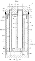
- Fig. 1 is a longitudinal cross-sectional view illustrating a first embodiment of a refrigerant container according to the present invention.
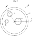
- Fig. 2 is a top view of a cap member portion of the refrigerant container illustrated in Fig. 1 .
- Fig. 3 is a partial cross-sectional view taken in the direction of arrows V-V passing through O in Fig. 2 .
- Fig. 4 is a longitudinal cross-sectional view of a strainer 40 integrally provided with a liquid-phase pipe holding portion 51 and an outer pipe 32 illustrated in Fig. 1 .
- Fig. 5 is a cross-sectional view taken in the direction of arrows A-A in Fig. 1 .
- a refrigerant container 1 of the first embodiment illustrated in the drawings is used for a heat pump system forming a car air-conditioner for an electric vehicle, for example.
- the refrigerant container 1 includes a closed-bottomed cylindrical tank 10 made of metal, such as stainless steel or aluminum alloy.
- the upper-face opening of the tank 10 is hermetically closed by a cap member (i.e., a cap portion) 12 made of the same metal.
- the refrigerant container 1 (or the tank 10) of the present embodiment is placed in a vertical position as illustrated in the drawings. That is, the refrigerant container 1 is placed with the cap member 12 positioned on the upper side and a bottom 13 of the tank 10 positioned on the lower side.
- the cap member 12 includes a gas/liquid inlet port 15, a stepped, small-diameter liquid-phase outlet port 16 having an intermediate large-diameter portion 16b, and a stepped, large-diameter gas-phase outlet port 17 having an intermediate large-diameter portion 17b, all of which penetrate through the cap member 12 such that they are open on the top and bottom sides thereof.
- the cap member 12 has a conduit connection adapter attached to its upper side, for example, such a conduit connection adapter as well as an internal screw portion for screwing the adapter is not illustrated.
- the liquid-phase outlet port 16 has coupled to its lower portion the upper end of an outlet pipe portion 20 (or a liquid-phase pipe 21 thereof) for a receiver that is adapted to guide only a liquid-phase refrigerant separated by the gas-liquid separator 18 to the side of an expansion valve via the liquid-phase outlet port 16.
- the gas-phase outlet port 17 has coupled to its lower portion the upper end of an outlet pipe portion 30 (or an inner pipe 31 thereof) for an accumulator with a double pipe structure, which includes the inner pipe 31 and the outer pipe 32, that is adapted to guide a gas-phase refrigerant separated by the gas-liquid separator 18 to the suction side of a compressor via the gas-phase outlet port 17 together with oil contained in the liquid-phase refrigerant (each member will be described in detail later).
- the strainer 40 for trapping foreign matter in the refrigerant is disposed at the bottom 13 of the tank 10.
- the strainer 40 includes a short cylindrical tubular case portion 42, which is adapted to be inserted (fitted) into the tank 10 in a press-fit manner so as to be placed at the bottom (i.e., the bottom face) 13 of the tank 10, and a cross-shaped baffle plate portion 43 integrally provided on the upper end of the tubular case portion 42 so as to partially cover the upper-face opening thereof.
- the cross-shaped baffle plate portion 43 has a plate-like shape as seen in a side view, and includes a sideways bridge portion 43a and a depthways bridge portion 43b as seen in a plan view ( Fig. 5 ).
- a reinforcing rib-like projection 43f is provided on the upper end face of the tubular case portion 42 and on the center of each of the upper faces of the sideways bridge portion 43a and the depthways bridge portion 43b.
- a portion around the left end of the sideways bridge portion 43a of the baffle plate portion 43 is integrally provided with the small-diameter short cylindrical liquid-phase pipe holding portion 51 that is adapted to have fixed thereto by press fit the lower end of the liquid-phase pipe 21 made of metal, such as aluminum alloy, and forming the outlet pipe portion 20 for the receiver.
- the outer pipe 32 forming the outlet pipe portion 30 for the accumulator is integrally provided on and extends from a portion where the sideways bridge portion 43a and the depthways bridge portion 43b cross each other on the right side of the center of the baffle plate portion 43.
- An oil return hole 35 is formed in the center of a portion of the baffle plate portion 43 provided with the outer pipe 32 (i.e., a portion corresponding to the bottom of the outer pipe 32). The diameter of the oil return hole 35 is set to about 1 mm, for example.
- a circular mesh filter 45 is integrally provided on the lower face side of the baffle plate portion 43 so as to cover the entire upper-face opening of the tubular case portion 42.
- the mesh filter 45 is produced using a metallic mesh or a mesh material of synthetic resin, for example. Accordingly, as is clearly seen in Fig. 5 , the mesh filter 45 is stretched across two pairs of (i.e., a total of four) large and small blade-shaped window portions 44a and 44b that are provided in portions of the upper-face opening of the tubular case portion 42 not covered with the baffle plate portion 43 and are defined by the tubular case portion 42, the sideways bridge portion 43a, and the depthways bridge portion 43b.
- the tubular case portion 42 of the strainer 40 is inserted into the tank 10 in a press-fit manner with the outer periphery of the tubular case portion 42 abutting the inner wall of the tank 10 so that the tubular case portion 42 is placed at the bottom 13 of the tank 10.
- the entire liquid-phase refrigerant falling from the upper portion of the tank 10 toward the bottom 13 passes through the mesh filter 45. This allows foreign matter in the liquid-phase refrigerant, which flows into the tubular case portion 42 via the mesh filter 45, to be trapped by the mesh filter 45 and thus removed from the circulating refrigerant.
- the mesh filter 45 is stretched across the four window portions 44a, 44a, 44b, and 44b in the present example, the mesh filter 45 may also be attached to the liquid-phase refrigerant drawing port 25 and the oil return hole 35.
- the mesh filter 45 need not cover the entire upper-face opening of the tubular case portion 42 as described above.
- the mesh filter 45 has only to cover at least a portion of the upper-face opening of the tubular case portion 42 not covered with the baffle plate portion 43.
- the aforementioned tubular case portion 42, baffle plate portion 43, liquid-phase pipe holding portion 51, and outer pipe 32 are integrally molded using synthetic resin.
- the mesh filter 45 is also integrated as an insert, for example.
- the inside diameter of the tank 10 is set to 60 to 90 mm
- the diameter of the tubular case portion 42 (or the baffle plate portion 43) is set substantially equal to the inside diameter of the tank 10
- the plate thickness of the baffle plate portion 43 is set to about 1 to 2 mm
- the height H ( Fig. 1 ) from the bottom face of the tank 10 to the baffle plate portion 43 (or the lower face thereof) is set to 5 to 10 mm.
- a plurality of (four in the example illustrated in the drawing) plate-like ribs 36 are provided in a manner protruding radially inward on the inner periphery of the lower portion of the outer pipe 32, which is integrally provided on the baffle plate portion 43, along the longitudinal direction (i.e., the vertical direction) and at equal angular intervals.
- the width (i.e., the radial width or the inward protrusion amount) of each plate-like rib 36 at a portion above its lower end 36m is slightly narrower the width of the lower end 36m.
- the inner pipe 31 (or the lower portion thereof) made of metal, such as aluminum alloy, is inserted in a press-fit manner on the inner peripheral side of a narrow-width portion 36n until the lower end of the inner pipe 31 engages with the upper end of the lower end 36m (i.e., a step portion adjacent to the narrow-width portion 36n) of each plate-like rib 36.
- the height (i.e., the vertical length) of each plate-like rib 36 is set to about 1/3 or 1/2 of the height of the outer pipe 32.
- the upper portion of the inner pipe 31 protrudes upward beyond the upper end of the outer pipe 32.
- the plate-like ribs 36 are provided on the side of the outer pipe 32 in the present example, the plate-like ribs 36 may be provided on the side of the inner pipe 31 or on both sides. In addition, it is needless to mention that the number of the plate-like ribs 36 is not limited to that illustrated in the drawing as long it is more than one.
- a pressure equalization hole 31f for preventing a liquid backflow to the side of the compressor while the system stops operation (ON ⁇ OFF) is provided in a portion of the inner pipe 31 at about the same level as the gas-liquid separator 18.
- liquid-phase pipe 21 (or the lower end thereof) made of metal, such as aluminum alloy, and forming the outlet pipe portion 20 for the receiver is press-fitted into and held by the liquid-phase pipe holding portion 51 that is integrally provided on the baffle plate portion 43 (until it abuts the baffle plate portion 43).
- the upper end (i.e., an expanded pipe portion) 21a of the outlet pipe portion 20 (or the liquid-phase pipe 21 thereof) for the receiver is expanded and fixed into the intermediate large-diameter portion 16b of the liquid-phase outlet port 16.
- the upper end (i.e., an expanded pipe portion) 31a of the outlet pipe portion 30 (or the inner pipe 31 thereof) for the accumulator is expanded and fixed into the intermediate large-diameter portion 17b of the gas-phase outlet port 17.
- the gas-liquid separator 18 is made of metal, such as stainless steel or aluminum alloy, and includes a disk-like ceiling portion 18a and a cylindrical peripheral wall portion 18b continuous with and extending downward from the outer periphery of the ceiling portion 18a.
- the gas-liquid separator 18 is disposed at a position below the lower end face of the gas/liquid inlet port 15 in the cap member 12 by a predetermined distance so as to cover the upper-end opening of the outer pipe 32 of the outlet pipe portion 30 for the accumulator (i.e., the upper portion of a space between the outer pipe 32 and the inner pipe 31, which is a downward-feed flow channel portion 33 described below) (i.e., so as to allow the upper end of the outer pipe 32 to be located between the ceiling portion 18a and the lower end of the peripheral wall portion 18b; see Fig. 3 ).
- the ceiling portion 18a of the gas-liquid separator 18 has through-holes 18u and 18v formed therein (side by side) that respectively allow the upper ends of the liquid-phase pipe 21 and the inner pipe 31, which are straight before being expanded, to be tightly inserted therethrough.
- the upper portions of the liquid-phase pipe 21 and the inner pipe 31 are respectively provided with flanged portions 21k and 31k, which have been subjected to compression bending, such as bulge forming, as lower-side latch portions adapted to engage with the gas-liquid separator 18 (or the peripheral edges of the through-holes 18u and 18v) on its lower side.
- the gas-liquid separator 18 is tightly held between the lower face of the cap member 12 (specifically, thick-walled cylindrical downward projections 12d and 12e provided in a protruding manner on the lower face of the cap member 12 around the liquid-phase outlet port 16 and the gas-phase outlet port 17) and the flanged portions 21k and 31k.
- the flanged portion 21k of the liquid-phase pipe 21 and the flanged portion 31k of the inner pipe 31 are located at the same level from the bottom 13 of the tank 10. Thus, the gas-liquid separator 18 (or the ceiling portion 18a thereof) is held horizontally.
- the flanged portions 21k and 31k are used as the lower-side latch portions in the present example, it is also possible to use thick-walled portions, which have been obtained by forming parts of the liquid-phase pipe 21 and the inner pipe 31 (i.e., at positions below the gas-liquid separator 18) to be thicker than the upper ends thereof passing through the through-holes 18u and 18v in the gas-liquid separator 18, so as to tightly hold the gas-liquid separator 18 between the lower face of the cap member 12 and the thick-walled portions, for example.
- a bag containing desiccants therein is usually disposed in the tank 10 by being wound around the outer pipe 32, for example.
- a bag containing desiccants therein and the like see Patent Literature 2, if necessary.
- the refrigerant container 1 with such a structure can be assembled as follows, for example.
- a refrigerant in a gas-liquid mixed state which has been introduced into the tank 10 from a condenser via the gas/liquid inlet port 15, collides with the gas-liquid separator 18 (or the ceiling portion 18a thereof) as illustrated in Fig. 3 , and diffuses radially, and is then separated into a liquid-phase refrigerant and a gas-phase refrigerant.
- the liquid-phase refrigerant (including oil) is guided into the lower space of the tank 10 by falling along the inner peripheral face of the tank 10, and the gas-phase refrigerant is guided into the upper space of the tank 10.
- one or more on-off valves provided in a refrigerant flow path are operated (see Patent Literature 2) so that the liquid-phase refrigerant guided to the lower space of the tank 10 passes through the mesh filter 45 of the strainer 40 and then accumulates in the tubular case portion 42.
- the mesh filter 45 When the liquid-phase refrigerant passes through the mesh filter 45, foreign matter, such as sludge, in the liquid-phase refrigerant is trapped by the mesh filter 45 and thus is removed from the circulating refrigerant.
- the liquid-phase refrigerant that has accumulated in the tubular case portion 42 is drawn into the liquid-phase pipe 21 through the liquid-phase refrigerant drawing port 25, and is then guided to the expansion valve via the liquid-phase outlet port 16.
- the refrigerant container 1 of the present embodiment functions as a receiver (also referred to as a receiver drier).
- one or more on-off valves provided in the refrigerant flow path are switched (see Patent Literature 2) so that the gas-phase refrigerant separated by the gas-liquid separator 18 is suctioned to the suction side of the compressor via the upper space of the tank 10 ⁇ a space between the outer pipe 32 and the inner pipe 31 (i.e., the downward-feed flow channel portion 33) ⁇ the lower end of the outer pipe 32 ⁇ the inside of the inner pipe 31 ⁇ the gas-phase outlet port 17, and thus is circulated.
- the liquid-phase refrigerant that has accumulated in the tubular case portion 42 hardly flows to the expansion valve due to the relationship of the pressure difference.
- oil that has accumulated in the tubular case portion 42 together with the liquid-phase refrigerant moves toward the bottom 13 of the tank 10 due to the difference in specific gravity, properties, and the like between the oil and the liquid-phase refrigerant, and is absorbed into the aforementioned gas-phase refrigerant to be suctioned to the suction side of the compressor via the downward-feed flow channel portion 33 ⁇ the lower end of the outer pipe 32 ⁇ the inside of the inner pipe 31 ⁇ the gas-phase outlet port 17.
- the oil is returned to the suction side of the compressor together with the gas-phase refrigerant through the oil return hole 35 provided in the baffle plate portion 43 at a position corresponding to the bottom of the outer pipe 32 ⁇ the inner pipe 31, and thus is circulated.
- the refrigerant container 1 of the present embodiment functions as an accumulator.
- the refrigerant container 1 of the present embodiment has both the functions of a receiver and an accumulator, and the receiver and the accumulator share the tank portion (i.e., the tank 10), the inlet port portion (i.e., the gas/liquid inlet port 15), the gas-liquid separation portion (i.e., the gas-liquid separator 18), and the strainer portion (i.e., the strainer 40) in common. Therefore, a rational structure with a small number of components can be provided.
- liquid-phase pipe holding portion 51 for the outlet pipe portion 20 for the receiver and the outer pipe 32 of the outlet pipe portion 30 for the accumulator are arranged side by side (with a gap therebetween) on the baffle plate portion 43 of the strainer 40.
- the liquid-phase pipe 21 is press-fitted into and held by the liquid-phase pipe holding portion 51, and the inner pipe 31 is press-fitted into and held by the outer pipe 32.
- components such as the cap member 12, the outlet pipe portion 20 for the receiver, the outlet pipe portion 30 for the accumulator, the strainer 40 (or the baffle plate portion 43), and the tank 10, are mechanically attached together through press fit, pipe expansion, or swaging that does not involve heating, for example.
- assembly can be carried out easily and promptly.
- an inexpensive synthetic resin material can be used as the material of the outlet pipe portion 20 for the receiver, the outlet pipe portion 30 for the accumulator, and the strainer 40 (or the baffle plate portion 43) more than before.
- tubular case portion 42 of the strainer 40 is inserted (or fitted) into the tank 10 in a press-fit manner so as to be placed at the bottom 13 of the tank 10, it is possible to reliably and stably hold the strainer 40 as well as the outlet pipe portion 20 for the receiver and the outlet pipe portion 30 for the accumulator, which are provided on the strainer 40, without additionally requiring a fastening means.
- Fig. 6 is a longitudinal cross-sectional view illustrating a second embodiment of a refrigerant container according to the present invention.
- Fig. 7 is a longitudinal cross-sectional view of a strainer 40' integrally provided with the liquid-phase pipe holding portion 51 and a gas-phase pipe holding portion 52 illustrated in Fig. 6 .
- Fig. 8 is a cross-sectional view taken in the direction of arrows B-B in Fig. 6 .
- a refrigerant container 2 of the second embodiment illustrated in the drawings differs from the refrigerant container 1 of the aforementioned first embodiment only in the portion related to an outlet pipe portion 30' for the accumulator.
- the other portions related to the outlet pipe portion 20 for the receiver and the like have the same structures as those of the refrigerant container 1 in the first embodiment. Therefore, portions corresponding to the respective portions of the refrigerant container 1 in the first embodiment are denoted by the same reference signs, and repeated description will be omitted.
- the differences will be mainly described.
- the baffle plate portion 43 of strainer 40' is provided with a large-diameter short cylindrical gas-phase pipe holding portion 52 instead of the outer pipe 32 of the refrigerant container 1 in the first embodiment.
- the gas-phase pipe holding portion 52 is adapted to have press-fitted thereinto the lower portion of an outer pipe 32' of a double pipe 30A that includes an inner pipe 31' and the outer pipe 32' (until it abuts the baffle plate portion 43).
- the oil return hole 35 is formed in the center of a portion of the baffle plate portion 43 corresponding to the bottom of the gas-phase pipe holding portion 52.
- the outlet pipe portion 30' for the accumulator includes the gas-phase pipe holding portion 52 and the double pipe 30A.
- the upper portion of the inner pipe 31' of the outlet pipe portion 30' for the accumulator protrudes upward beyond the upper end of the outer pipe 32', and the upper end 31a of the inner pipe 31' is expanded and fixed into the intermediate large-diameter portion 17b of the gas-phase outlet port 17 as in the first embodiment.
- the double pipe 30A of the present embodiment is integrally molded by extrusion using metal, such as aluminum alloy, for example.
- the inner pipe 31' and the outer pipe 32' of the double pipe 30A are integrally coupled together by a plurality of (three in the example illustrated in the drawing) plate-like ribs 37 that are provided radially at equal angular intervals in the longitudinal direction between the inner pipe 31' and the outer pipe 32'.
- the upper ends of the plurality of plate-like ribs 37 extend upward beyond the upper end of the outer pipe 32', and such extension portions 37e (or the upper ends thereof) are adapted to serve as lower-side latch portions for the gas-liquid separator 18 as with the flanged portion 31k of the first embodiment.
- Each of such extension portions 37e may also be referred to as a thick-walled portion formed thicker than the upper end thereof that passes through the through-holes 18v in the gas-liquid separator 18.
- the gas-liquid separator 18 is tightly held between the lower face of the cap member 12 (or the downward projections 12d and 12e thereof) and the flanged portion 21k provided on the liquid-phase pipe 21 as well as the extension portions 37e of the plurality of plate-like ribs 37 on the double pipe 30A.
- the inner pipe 31' and the outer pipe 32' are integrated via the plate-like ribs 37 in the present example, the inner pipe 31' and the outer pipe 32' may be formed separately (as separate members), and the plate-like ribs 37 may be provided on one or both of the inner pipe 31' and the outer pipe 32' as in the first embodiment.
- the refrigerant container 2 of the present second embodiment with such a structure can obtain operational advantages substantially similar to those of the refrigerant container 1 in the first embodiment.
- the baffle plate portion 43 of the strainer 40' is provided with the short cylindrical gas-phase pipe holding portion 52 instead of the long outer pipe 32 of the refrigerant container 1 in the first embodiment, the strainer 40' can be molded more easily than that of the first embodiment, resulting in a lower production cost.
- the assembly performance improves in comparison with the refrigerant container of the first embodiment in which the inner pipe and the outer pipe are formed separately and using different materials.
- the extension portions 37e of the plate-like ribs 37 are adapted to serve as the lower-side latch portions for the gas-liquid separator 18 as with the flanged portion 31k of the first embodiment, there is no need to provide the inner pipe 31' with the flanged portion 31k in the present embodiment.
- the machining and assembly costs can be suppressed.
- Fig. 9 is a longitudinal cross-sectional view illustrating a third embodiment of a refrigerant container according to the present invention.
- a refrigerant container 3 in the third embodiment illustrated in the drawing differs from the refrigerant container 1 in the aforementioned first embodiment in the method of fixedly attaching the liquid-phase pipe 21 and the inner pipe 31 to the cap member 12 and in the method of fixedly attaching the gas-liquid separator 18.
- Portions other than the portions related to the fixed attachment methods have the same structures as those of the refrigerant container 1 in the first embodiment. Therefore, portions corresponding to the respective portions of the refrigerant container 1 in the first embodiment are denoted by the same reference signs, and repeated description will be omitted.
- the differences will be mainly described.
- the liquid-phase pipe 21 forming the outlet pipe portion 20 for the receiver and the inner pipe 31 forming the outlet pipe portion 30 for the accumulator are substantially straight pipes without irregularities, steps, or protrusions over their entire length before being attached to the cap member 12. Even after the liquid-phase pipe 21 and the inner pipe 31 are attached to the cap member 12, their upper ends are only inserted into the lower portions (i.e., the lower large-diameter portions) of the liquid-phase outlet port 16 and the gas-phase outlet port 17, respectively, in the cap member 12, and are not expanded.
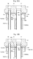
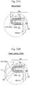
- Fig. 10A is a view illustrating the state in which the upper ends of the liquid-phase pipe 21 and the inner pipe 31 are respectively inserted into the lower portions of the liquid-phase outlet port 16 and the gas-phase outlet port 17 (i.e., the state before they are fixedly attached (fixed by swaging)).
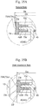
- Fig. 10B is a view illustrating the state in which the liquid-phase pipe 21, the inner pipe 31, and the gas-liquid separator 18 are fixedly attached to the cap member 12 by swaging (i.e., fixed by swaging).
- a short cylindrical portion 12i which has an inside diameter substantially equal to the outside diameter of the liquid-phase pipe 21, is provided in a downwardly protruding manner around the peripheral edge of the lower end of the liquid-phase outlet port 16 in the cap member 12.
- a thick-walled short cylindrical portion 12j which has an inside diameter substantially equal to the outside diameter of the inner pipe 31, is provided around the peripheral edge of the lower end of the gas-phase outlet port 17 in the cap member 12 (or the downward projection 12e thereof).
- a thin-walled short cylindrical portion 12k which has an outside diameter substantially equal to the opening diameter of the through-hole 18v' formed in the gas-liquid separator 18, is provided in a downwardly protruding manner, continuously with the lower end of the outer peripheral portion of the thick-walled short cylindrical portion 12j (that is, around the inner pipe 31 inserted into the gas-phase outlet port 17).
- the through-hole portion which is adapted to pass the liquid-phase pipe 21, in the gas-liquid separator 18 is a short cylindrical through-hole 18u' formed by partially bending the gas-liquid separator 18 downward to increase the holding property.
- the upper end of the liquid-phase pipe 21 is first inserted into the lower portion (i.e., the lower large-diameter portion) of the liquid-phase outlet port 16, and the short cylindrical portion 12i is swaged inward so as to attach the liquid-phase pipe 21 to the cap member 12 (i.e., a swaged portion 12i').
- the upper end of the inner pipe 31 is inserted into the lower portion (i.e., the lower large-diameter portion) of the gas-phase outlet port 17, and also, the liquid-phase pipe 21 and the inner pipe 31 are respectively passed through the through-holes 18u' and 18v' in the gas-liquid separator 18 from below.
- the gas-liquid separator 18 is moved until its ceiling face 18a abuts the downward projection 12e (or the lower face thereof) of the cap member 12.
- the thick-walled short cylindrical portion 12j and the thin-walled short cylindrical portion 12k are swaged using a swaging jig 65 as illustrated in Fig. 10B .
- the swaging jig 65 includes a cylindrical base portion 65a adapted to be slidably arranged around the inner pipe 31, an annular blade portion 65b provided in a protruding manner on the upper-end inner peripheral portion of the cylindrical base portion 65a and having a cutting edge, which has a substantially right triangular cross-section, and a flat face portion 65c extending to the outer peripheral side than does the annular blade portion 65b on the upper end face of the cylindrical base portion 65a.
- the inner peripheral side of the thick-walled short cylindrical portion 12j is bent radially inward so as to slightly bite into the inner pipe 31 (i.e., a swaged portion 12j'). Accordingly, the inner pipe 31 is attached to the cap member 12, and at the same time, the thin-walled short cylindrical portion 12k is bent outward by the flat face portion 65c (i.e., a swaged portion 12k').
- the peripheral edge of the through-hole 18v' in the gas-liquid separator 18 is sandwiched and held between the thin-walled short cylindrical portion 12k (i.e., the swaged portion 12k') and the lower face of the cap member 12 (or the downward projection 12e thereof).
- the lower end of the liquid-phase pipe 21 is press-fitted into the liquid-phase pipe holding portion 51, and also, the inner pipe 31 is press-fitted into the outer pipe 32 so that an assembly including the cap member 12, the liquid-phase pipe 21, the inner pipe 31, the gas-liquid separator 18, and the strainer 40 is obtained.
- the tank 10 is disposed around the interior member 60 (i.e., a portion other than and below the cap member 12) of the assembly (from below; see Fig. 9 ), and the strainer 40 is pushed into the tank 10 in a press-fit manner so as to be placed at the bottom 13 of the tank 10.
- the cap member 12 is joined to the upper end of the tank 10 by welding.
- the refrigerant container 3 of the present third embodiment with such a structure can obtain operational advantages substantially similar to those of the refrigerant container 1 in the first embodiment.
- liquid-phase pipe 21 and the inner pipe 31 need not be machined at all and the gas-liquid separator 18 need not be modified to a great degree, the machining and assembly costs can be further suppressed.
- the gas-liquid separator 18 is fixed to the cap member 12 by swaging at a position around the outlet pipe portion 30 (or the inner pipe 31 thereof) for the accumulator coupled to the gas-phase outlet port 17
- the gas-liquid separator 18 may be fixed to the cap member 12 by swaging at a position around the outlet pipe portion 20 (or the liquid-phase pipe 21 thereof) for the receiver coupled to the liquid-phase outlet port 16.
- Fig. 11 is a longitudinal cross-sectional view illustrating a fourth embodiment of a refrigerant container according to the present invention.
- a refrigerant container 4 in the fourth embodiment illustrated in the drawing differs from the refrigerant container 3 in the aforementioned third embodiment only in that the thick-walled short cylindrical portion 12j for fixing the inner pipe 31 to the cap member 12 by swaging is not provided and also in that an O-ring 67 is provided as a sealant between the gas-phase outlet port 17 in the cap member 12 and the upper end of the inner pipe 31. Therefore, portions corresponding to the respective portions of the refrigerant container 3 in the third embodiment are denoted by the same reference signs, and repeated description will be omitted. Hereinafter, the differences will be mainly described.
- the lower portion of the inner pipe 31 is press-fitted into the outer pipe 32 provided on the baffle plate portion 43 of the strainer 40.
- the upper end of the inner pipe 31 is only inserted into the lower portion (i.e., the lower large-diameter portion) of the gas-phase outlet port 17 and is not fixed.
- the O-ring 67 is provided as a sealant between the gas-phase outlet port 17 and the upper end of the inner pipe 31 (specifically, an inner peripheral groove provided in the gas-phase outlet port 17).
- the refrigerant container 4 of the present fourth embodiment with such a structure can obtain operational advantages substantially similar to those of the refrigerant container 1 in the first embodiment.
- the inner pipe 31 is not attached to the cap member 12 through pipe expansion or swaging, but the inner pipe 31 is fixedly held by fixing the strainer 40 (or the baffle plate portion 43 thereof) to the tank 10 in a press-fit manner and also fixing the inner pipe 31 to the outer pipe 32 integrally provided on the baffle plate portion 43 by press fit, and further providing the O-ring 67 between the gas-phase outlet port 17 in the cap member 12 and the upper end of the inner pipe 31. Therefore, the assembly step can be simplified and the production cost can be suppressed. In such a case, since the O-ring 67 is provided between the gas-phase outlet port 17 and the upper end of the inner pipe 31, there is no possibility that a refrigerant will undesirably leak from the gas-phase outlet port 17.
- Fig. 12 is a longitudinal cross-sectional view illustrating a fifth embodiment of a refrigerant container according to the present invention.
- Fig. 13 is a top view of a cap member portion of the refrigerant container illustrated in Fig. 12 .
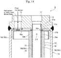
- Fig. 14 is a partial cross-sectional view taken in the direction of arrows V-V passing through O in Fig. 13 .
- Fig. 15 is a longitudinal cross-sectional view illustrating a strainer portion in Fig. 12 together with an outer pipe and a liquid-phase pipe, which are integrally provided on the strainer portion, and a gas-liquid separator.
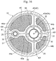
- Fig. 16 is a cross-sectional view taken in the direction of arrows A-A in Fig. 12 .
- a refrigerant container 5 of the fifth embodiment illustrated in the drawings is used for a heat pump system forming a car air-conditioner for an electric vehicle, for example.
- the refrigerant container 5 includes a closed-bottomed cylindrical tank 10 made of metal, such as stainless steel or aluminum alloy.
- the upper-face opening of the tank 10 is hermetically closed by a cap member (i.e., a cap portion) 12 made of the same metal.
- the refrigerant container 5 (or the tank 10) of the present embodiment is placed in a vertical position as illustrated in the drawings. That is, the refrigerant container 5 is placed with the cap member 12 positioned on the upper side and a bottom 13 of the tank 10 positioned on the lower side.
- the cap member 12 includes a gas/liquid inlet port 15, a stepped, small-diameter liquid-phase outlet port 16 having a lower large-diameter portion 16a, and a stepped, large-diameter gas-phase outlet port 17 having a lower large-diameter portion 17a, all of which penetrate through the cap member 12 such that they are open on the top and bottom sides thereof.
- the cap member 12 has a conduit connection adapter attached to its upper side, for example, such a conduit connection adapter as well as an internal screw portion for screwing the adapter is not illustrated.
- the lower large-diameter portion 16a of the liquid-phase outlet port 16 has inserted thereinto an upper end 21a of an outlet pipe portion 20 (or a liquid-phase pipe 21 thereof) for a receiver that is adapted to guide only a liquid-phase refrigerant separated by the gas-liquid separator 18 to the side of an expansion valve via the liquid-phase outlet port 16.
- the lower large-diameter portion 17a of the gas-phase outlet port 17 has inserted thereinto an upper end 31a of an outlet pipe portion 30 (or an inner pipe 31 thereof) for an accumulator with a double pipe structure, which includes the inner pipe 31 and the outer pipe 32 provided around the outer periphery of the inner pipe 31, that is adapted to guide a gas-phase refrigerant separated by the gas-liquid separator 18 to the suction side of a compressor via the gas-phase outlet port 17 together with oil contained in the liquid-phase refrigerant (which will be described in detail later).
- the gas-liquid separator 18 is made of metal, such as stainless steel or aluminum alloy, and includes a disk-like ceiling portion 18a and a cylindrical peripheral wall portion 18b continuous with and extending downward from the outer periphery of the ceiling portion 18a.
- the gas-liquid separator 18 is disposed at a position below the lower end face of the gas/liquid inlet port 15 in the cap member 12 by a predetermined distance so as to cover the upper-end opening of the outer pipe 32 of the outlet pipe portion 30 for the accumulator (i.e., the upper portion of a space between the outer pipe 32 and the inner pipe 31, which is a downward-feed flow channel portion 33 described below) (i.e., so as to allow the upper end of the outer pipe 32 to be located between the ceiling portion 18a and the lower end of the peripheral wall portion 18b; see Fig. 14 ).
- the ceiling portion 18a of the gas-liquid separator 18 has through-holes 18u and 18v formed therein (side by side) that respectively allow the upper end 21a of the straight liquid-phase pipe 21 and the upper end 31a of the straight inner pipe 31 to be tightly inserted therethrough (see also Fig. 15 ).
- the strainer 40 for trapping foreign matter in the refrigerant is disposed at the bottom 13 of the tank 10.
- the strainer 40 includes a short cylindrical tubular case portion 42, which is adapted to be inserted (fitted) into the tank 10 in a press-fit manner so as to be placed at the bottom (i.e., the bottom face) 13 of the tank 10, and a cross-shaped baffle plate portion 43 integrally provided on the upper end of the tubular case portion 42 so as to partially cover the upper-face opening thereof.
- the cross-shaped baffle plate portion 43 has a plate-like shape as seen in a side view, and includes a sideways bridge portion 43a and a depthways bridge portion 43b as seen in a plan view ( Fig. 16 ).
- a reinforcing rib-like projection 43f is provided on the upper end face of the tubular case portion 42 and on the center of each of the upper faces of the sideways bridge portion 43a and the depthways bridge portion 43b.
- a portion around the left end of the sideways bridge portion 43a of the baffle plate portion 43 is integrally provided with a small-diameter short cylindrical liquid-phase pipe holding portion 51 that is adapted to have fixed thereto by press fit the lower end of the liquid-phase pipe 21 made of metal, such as aluminum alloy, and forming the outlet pipe portion 20 for the receiver.
- a liquid-phase refrigerant drawing port 25 which has a diameter slightly smaller than the inside diameter of the liquid-phase pipe holding portion 51, is formed in a portion of the baffle plate portion 43 (or the sideways bridge portion 43a thereof) corresponding to the bottom of the liquid-phase pipe holding portion 51.
- the outer pipe 32 forming the outlet pipe portion 30 for the accumulator is integrally provided on and extends from a portion where the sideways bridge portion 43a and the depthways bridge portion 43b cross each other on the right side of the center of the baffle plate portion 43.
- An oil return hole 35 is formed in the center of a portion of the baffle plate portion 43 provided with the outer pipe 32 (i.e., a portion corresponding to the bottom of the outer pipe 32).
- the diameter of the oil return hole 35 is set to about 1 mm, for example.
- the outer pipe 32 has the straight inner pipe 31 made of metal, such as aluminum alloy, fixed thereto by press fit (which will be described in detail later).
- a circular mesh filter 45 is integrally provided on the lower face side of the baffle plate portion 43 so as to cover the entire upper-face opening of the tubular case portion 42.
- the mesh filter 45 is produced using a metallic mesh or a mesh material of synthetic resin, for example. Accordingly, as is clearly seen in Fig. 16 , the mesh filter 45 is stretched across two pairs of (i.e., a total of four) large and small blade-shaped window portions 44a and 44b that are provided in portions of the upper-face opening of the tubular case portion 42 not covered with the baffle plate portion 43 and are defined by the tubular case portion 42, the sideways bridge portion 43a, and the depthways bridge portion 43b.
- the tubular case portion 42 of the strainer 40 is inserted into the tank 10 in a press-fit manner with the outer periphery of the tubular case portion 42 abutting the inner wall of the tank 10 so that the tubular case portion 42 is placed at the bottom 13 of the tank 10.
- the entire liquid-phase refrigerant falling from the upper portion of the tank 10 toward the bottom 13 passes through the mesh filter 45. This allows foreign matter in the liquid-phase refrigerant, which flows into the tubular case portion 42 via the mesh filter 45, to be trapped by the mesh filter 45 and thus removed from the circulating refrigerant.
- the mesh filter 45 is stretched across the four window portions 44a, 44a, 44b, and 44b in the present example, the mesh filter 45 may also be attached to the liquid-phase refrigerant drawing port 25 and the oil return hole 35.
- the mesh filter 45 need not cover the entire upper-face opening of the tubular case portion 42 as described above.
- the mesh filter 45 has only to cover at least a portion of the upper-face opening of the tubular case portion 42 not covered with the baffle plate portion 43.
- the aforementioned tubular case portion 42, baffle plate portion 43, liquid-phase pipe holding portion 51, and outer pipe 32 are integrally molded using synthetic resin.
- the mesh filter 45 is also integrated as an insert, for example.
- the inside diameter of the tank 10 is set to 60 to 90 mm
- the diameter of the tubular case portion 42 (or the baffle plate portion 43) is set substantially equal to the inside diameter of the tank 10
- the plate thickness of the baffle plate portion 43 is set to about 1 to 2 mm
- the height H ( Fig. 12 ) from the bottom face of the tank 10 to the baffle plate portion 43 (or the lower face thereof) is set to 5 to 10 mm.
- the lower-side flanged portion 21b is used as the lower-side latch portion in the present example, it is also possible to use a large-diameter portion, which has a diameter larger than that of the upper end 21a passing through the through-hole 18u in the gas-liquid separator 18, a rib, which protrudes radially outward on the side below the through-hole 18u in the gas-liquid separator 18, or a thick-walled portion, for example, and allow it to engage with the gas-liquid separator 18 (or the peripheral edge of the through-hole 18u therein) on its lower side, for example.
- a plurality of (four in the example illustrated in the drawing) plate-like ribs 36 are provided in a manner protruding radially inward on the inner periphery of the outer pipe 32, which is integrally provided on the baffle plate portion 43, along the longitudinal direction (i.e., the vertical direction) and at equal angular intervals.
- Each plate-like rib 36 includes, from its lower end side to its upper end side, a lowermost wide-width portion 36a, which is adapted to have the lower end of the inner pipe 31 disposed thereon and engage therewith, a lower narrow-width portion 36b having a width (i.e., a radial width or an inward protrusion amount) slightly smaller than that of the lowermost wide-width portion 36a, and an upper narrow-width portion 36c having a width slightly smaller than that of the lower narrow-width portion 36b.
- a lowermost wide-width portion 36a which is adapted to have the lower end of the inner pipe 31 disposed thereon and engage therewith
- a lower narrow-width portion 36b having a width (i.e., a radial width or an inward protrusion amount) slightly smaller than that of the lowermost wide-width portion 36a
- an upper narrow-width portion 36c having a width slightly smaller than that of the lower narrow-width portion 36b.
- the inner pipe 31 (or the lower portion thereof) made of metal, such as aluminum alloy, is inserted and fixed on the inner peripheral side of the lower narrow-width portion 36b by press fit until the lower end of the inner pipe 31 engages with the upper end of the lowermost wide-width portion 36a (i.e., a step portion adjacent to the lower narrow-width portion 36b).
- the position of the upper end of the lower narrow-width portion 36b is set to about 1/3 or 1/2 of the height of the outer pipe 32
- the height (i.e., the vertical length) of the lower narrow-width portion 36b is set to about 1/4 or 1/3 of the height of the outer pipe 32
- a gap is formed between the inner end of the upper narrow-width portion 36c and the outer peripheral face of the inner pipe 31.
- the plate-like ribs 36 are provided on the side of the outer pipe 32 in the present example, the plate-like ribs 36 may be provided on the side of the inner pipe 31 or on both sides.
- the number of the plate-like ribs 36 provided between the inner pipe 31 and the outer pipe 32 is not limited to that illustrated in the drawing as long it is more than one.
- the upper ends of the plurality of plate-like ribs 36 extend upward beyond the upper end of the outer pipe 32, and such extension portions 36e (or the upper ends thereof) are adapted to serve as lower-side latch portions for the gas-liquid separator 18 as with the lower-side flanged portion 21b of the liquid-phase pipe 21 that is adapted to engage with the gas-liquid separator 18 (or the peripheral edge of the through-hole 18v therein) on its lower side.
- the lower-side flanged portion 21b (or the upper end thereof) of the liquid-phase pipe 21 and the extension portions 36e (or the upper ends thereof) of the plate-like ribs 36 are located at the same level from the bottom 13 of the tank 10. Thus, the gas-liquid separator 18 (or the ceiling portion 18a thereof) is held horizontally.
- the upper portion of the inner pipe 31 (at a predetermined position below its upper end 31a inserted into the lower large-diameter portion 17a of the gas-phase outlet port 17) is provided with an upper-side flanged portion 31b, which has been subjected to compression bending, such as bulge forming, as an upper-side pressing portion capable of pressing the gas-liquid separator 18 (or the peripheral edge of the through-hole 18v therein) from its upper side.
- the gas-liquid separator 18 is tightly held between the lower-side flanged portion 21b formed on the liquid-phase pipe 21 and the extension portions 36e of the plate-like ribs 36 formed on the outer pipe 32, each serving as the lower-side latch portion, and the upper-side flanged portion 31b formed on the inner pipe 31 and serving as the upper-side pressing portion.
- the upper-side flanged portion 31b is used as the upper-side pressing portion in the present example, it is also possible to use a large-diameter portion, which has a diameter larger than that of the upper end 31a passing through the through-hole 18v in the gas-liquid separator 18, or a thick-walled portion, for example, and allow it to engage with the gas-liquid separator 18 (or the peripheral edge of the through-hole 18v therein) on its upper side.
- a pressure equalization hole 31f for preventing a liquid backflow to the side of the compressor while the system stops operation (ON ⁇ OFF) is provided in a portion of the inner pipe 31 at about the same level as the gas-liquid separator 18.
- the upper end 21a of the outlet pipe portion 20 (or the liquid-phase pipe 21 thereof) for the receiver is inserted into the lower large-diameter portion 16a of the liquid-phase outlet port 16 (through the through-hole 18u in the gas-liquid separator 18).
- the upper end 31a of the outlet pipe portion 30 (or the inner pipe 31 thereof) for the accumulator is inserted into the lower large-diameter portion 17a of the gas-phase outlet port 17 (through the through-hole 18v in the gas-liquid separator 18).
- a bag containing desiccants therein is usually disposed in the tank 10 by being wound around the outer pipe 32, for example.
- a bag containing desiccants therein and the like see Patent Literature 2, if necessary.
- the refrigerant container 5 with such a structure can be assembled as follows, for example.
- a refrigerant in a gas-liquid mixed state which has been introduced into the tank 10 from a condenser via the gas/liquid inlet port 15, collides with the gas-liquid separator 18 (or the ceiling portion 18a thereof) as illustrated in Fig. 14 , and diffuses radially, and is then separated into a liquid-phase refrigerant and a gas-phase refrigerant.
- the liquid-phase refrigerant (including oil) is guided into the lower space of the tank 10 by falling along the inner peripheral face of the tank 10, and the gas-phase refrigerant is guided into the upper space of the tank 10.
- one or more on-off valves provided in a refrigerant flow path are operated (see Patent Literature 2) so that the liquid-phase refrigerant guided to the lower space of the tank 10 passes through the mesh filter 45 of the strainer 40 and then accumulates in the tubular case portion 42.
- the mesh filter 45 When the liquid-phase refrigerant passes through the mesh filter 45, foreign matter, such as sludge, in the liquid-phase refrigerant is trapped by the mesh filter 45 and thus is removed from the circulating refrigerant.
- the liquid-phase refrigerant that has accumulated in the tubular case portion 42 is drawn into the liquid-phase pipe 21 through the liquid-phase refrigerant drawing port 25, and is then guided to the expansion valve via the liquid-phase outlet port 16.
- the refrigerant container 5 of the present embodiment functions as a receiver (also referred to as a receiver drier).
- one or more on-off valves provided in the refrigerant flow path are switched (see Patent Literature 2) so that the gas-phase refrigerant separated by the gas-liquid separator 18 is suctioned to the suction side of the compressor via the upper space of the tank 10 ⁇ a space between the outer pipe 32 and the inner pipe 31 (i.e., the downward-feed flow channel portion 33) ⁇ the lower end of the outer pipe 32 ⁇ the inside of the inner pipe 31 ⁇ the gas-phase outlet port 17, and thus is circulated.
- the liquid-phase refrigerant that has accumulated in the tubular case portion 42 hardly flows to the expansion valve due to the relationship of the pressure difference.
- oil that has accumulated in the tubular case portion 42 together with the liquid-phase refrigerant moves toward the bottom 13 of the tank 10 due to the difference in specific gravity, properties, and the like between the oil and the liquid-phase refrigerant, and is absorbed into the aforementioned gas-phase refrigerant to be suctioned to the suction side of the compressor via the downward-feed flow channel portion 33 ⁇ the lower end of the outer pipe 32 ⁇ the inside of the inner pipe 31 ⁇ the gas-phase outlet port 17.
- the oil is returned to the suction side of the compressor together with the gas-phase refrigerant through the oil return hole 35 provided in the baffle plate portion 43 at a position corresponding to the bottom of the outer pipe 32 ⁇ the inner pipe 31, and thus is circulated.
- the refrigerant container 5 of the present embodiment functions as an accumulator.
- the refrigerant container 5 of the present embodiment has both the functions of a receiver and an accumulator, and the receiver and the accumulator share the tank portion (i.e., the tank 10), the inlet port portion (i.e., the gas/liquid inlet port 15), the gas-liquid separation portion (i.e., the gas-liquid separator 18), and the strainer portion (i.e., the strainer 40) in common. Therefore, a rational structure with a small number of components can be provided.
- liquid-phase pipe holding portion 51 for the outlet pipe portion 20 for the receiver and the outer pipe 32 of the outlet pipe portion 30 for the accumulator are arranged side by side (with a gap therebetween) on the baffle plate portion 43 of the strainer 40.
- the liquid-phase pipe 21 is press-fitted into and held by the liquid-phase pipe holding portion 51, and the inner pipe 31 is press-fitted into and held by the outer pipe 32.
- the gas-liquid separator is not supported by engaging on its lower side with a lower-side latch portion that is formed by partially reducing the thickness of the outlet pipe.
- the outlet pipe portion 30 for the accumulator is formed as a double pipe (structure) of the inner pipe 31 and the outer pipe 32, and the gas-liquid separator 18 is supported by engaging on its lower side with lower-side latch portions including the extension portions 36e of the plurality of plate-like ribs 36 that are provided between the inner pipe 31 and the outer pipe 32 (specifically, on the inner periphery of the outer pipe 32) so as to couple the inner pipe 31 and the outer pipe 32 together (and the lower-side flanged portion 21b provided on the liquid-phase pipe 21).
- the refrigerant container 5 of the present embodiment has an increased force of holding the gas-liquid separator 18 (in particular, a support force acting from below) and thus has increased stability.
- the gas-liquid separator 18 in particular, a support force acting from below
- backlash and tilt of the gas-liquid separator 18 can be suppressed, and the desired gas-liquid separation performance can be obtained.
- components such as the cap member 12, the outlet pipe portion 20 for the receiver, the outlet pipe portion 30 for the accumulator, the strainer 40 (or the baffle plate portion 43), and the tank 10, are mechanically attached together by press fit that does not involve heating, for example.
- press fit that does not involve heating, for example.
- an inexpensive synthetic resin material can be used as the material of the outlet pipe portion 20 for the receiver, the outlet pipe portion 30 for the accumulator, and the strainer 40 (or the baffle plate portion 43) more than before.
- tubular case portion 42 of the strainer 40 is inserted (or fitted) into the tank 10 in a press-fit manner so as to be placed at the bottom 13 of the tank 10, it is possible to reliably and stably hold the strainer 40 as well as the outlet pipe portion 20 for the receiver and the outlet pipe portion 30 for the accumulator, which are provided on the strainer 40, without additionally requiring a fastening means.
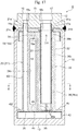
- Fig. 17 is a longitudinal cross-sectional view illustrating a sixth embodiment of a refrigerant container according to the present invention.
- Fig. 18 is a longitudinal cross-sectional view illustrating a strainer portion in Fig. 17 together with a liquid-phase pipe and an outer pipe.
- Fig. 19 is a cross-sectional view taken in the direction of arrows B-B in Fig. 17 .
- a refrigerant container 6 of the sixth embodiment illustrated in the drawings differs from the refrigerant container 5 of the aforementioned fifth embodiment mainly in the portion related to an outlet pipe portion 20' for the receiver.
- the other portions related to the outlet pipe portion 30 for the accumulator and the like basically have the same structures as those of the refrigerant container 5 in the fifth embodiment. Therefore, portions corresponding to the respective portions of the refrigerant container 5 in the fifth embodiment are denoted by the same reference signs, and repeated description will be omitted.
- the differences will be mainly described.
- the outlet pipe portion 20' for the receiver includes only a liquid-phase pipe 21' that is integrally provided on and extends from the baffle plate portion 43 of the strainer 40.
- the right side face portion of the liquid-phase pipe 21' and the left side face portion of the outer pipe 32 that is also integrally provided on the baffle plate portion 43 are integrally coupled together by a frame-shaped rectangular coupling plate (i.e., coupling portion) 24, which has an elongated rounded rectangular opening 24a in the center, for reinforcement purposes, for example.
- the coupling plate 24 is integrally coupled at its lower side portion (i.e., lower end) to the sideways bridge portion 43a of the baffle plate portion 43, is integrally coupled at its right side portion to the left side face portion of the outer pipe 32 (or the plate-like rib 36 on the left side coupled thereto), and is integrally coupled at its left side portion to the right side face portion of the liquid-phase pipe 21'.
- the upper end face of the coupling plate 24 (or the upper side portion thereof) is flush with (at the same level as) the upper end faces of the extension portions 36e of the plate-like ribs 36.
- the upper end of the liquid-phase pipe 21' at a position above the upper end face of the coupling plate 24 is formed slightly thinner than the other portions of the liquid-phase pipe 21' (that is, a portion of the liquid-phase pipe 21' at a position below the upper end face of the coupling plate 24 is formed slightly thicker than the other portions of the liquid-phase pipe 21').
- a stepped face (i.e., a shoulder face) 21c defined by an upper-end thin-walled portion 21a' and a portion below the upper-end thin-walled portion 21a' (i.e., a thick-walled portion or a large-diameter portion) of the liquid-phase pipe 21' is flush with (at the same level as) the upper end face of the coupling plate 24.
- the tubular case portion 42 of the strainer 40, the baffle plate portion 43, the outlet pipe portion 20' (or the liquid-phase pipe 21') for the receiver, and the outer pipe 32 of the outlet pipe portion 30 for the accumulator are integrally molded using synthetic resin.
- the liquid-phase pipe 21' is not provided with the lower-side flanged portion 21b in the fifth embodiment.
- the stepped face (i.e., the shoulder face) 21c of the liquid-phase pipe 21', the coupling plate 24 (or the upper end face thereof), and the extension portions 36e of the plate-like ribs 36 are provided as lower-side latch portions that are adapted to engage with the gas-liquid separator 18 on its lower side.
- the opening 24a in the aforementioned coupling plate 24 is used for winding a bag containing desiccants therein around the outer pipe 32 and thus allowing the bag to be held thereon, for example.
- a bag containing desiccants therein and the like see Patent Literature 2, if necessary.
- reductions in the weight and material cost can also be achieved, for example.
- the refrigerant container 6 with such a structure can be assembled as follows, for example.
- the refrigerant container 6 of the present sixth embodiment with such a structure can obtain operational advantages substantially similar to those of the refrigerant container 5 in the fifth embodiment.
- the tubular case portion 42 of the strainer 40, the baffle plate portion 43, the outlet pipe portion 20' (or the liquid-phase pipe 21') for the receiver, and the outer pipe 32 of the outlet pipe portion 30 for the accumulator are integrally molded using synthetic resin, there is no need to separately prepare the liquid-phase pipe 21' made of metal. Therefore, it is possible to reduce the number of components and production steps, and increase the proportion of synthetic resin portions that can be produced at a lower cost than metal components as compared to the refrigerant container 5 in the fifth embodiment. This can further suppress the component costs and the machining and assembly costs.
- the liquid-phase pipe 21' and the outer pipe 32 are integrally coupled together by the coupling plate 24, and the coupling plate 24 serves as a reinforcing member for the outlet pipe portion 20' (or the liquid-phase pipe 21') for the receiver and also as a lower-side latch portion.
- the coupling plate 24 serves as a reinforcing member for the outlet pipe portion 20' (or the liquid-phase pipe 21') for the receiver and also as a lower-side latch portion.
- Fig. 20 is a longitudinal cross-sectional view illustrating a seventh embodiment of a refrigerant container according to the present invention.
- Fig. 21 is a cross-sectional view taken in the direction of arrows C-C in Fig. 20 .
- a refrigerant container 7 of the seventh embodiment illustrated in the drawings also, portions corresponding to the respective portions of the refrigerant containers 5 and 6 in the aforementioned fifth and sixth embodiments are denoted by the same or related reference signs, and repeated description will be omitted. Hereinafter, the differences will be mainly described.
- the baffle plate portion 43 is integrally provided with the liquid-phase pipe 21' and the gas-phase pipe holding portion 52 instead of the liquid-phase pipe holding portion 51 and the outer pipe 32 in the fifth embodiment.
- the outlet pipe portion 20' for the receiver includes only the liquid-phase pipe 21' that is integrally provided on and extends from the baffle plate portion 43 of the strainer 40'.
- one or more (three in the example illustrated in the drawing) plate-like ribs 26 are provided radially at equal angular intervals on the outer peripheral portion of the liquid-phase pipe 21'.
- the plate-like ribs 26 are provided along the longitudinal direction across a region from the lower end of the liquid-phase pipe 21' (or the baffle plate portion 43) to the stepped face (i.e., the shoulder face) 21c at the lower end of the upper-end thin-walled portion 21a'.
- the plate-like ribs 26 are adapted to serve the function of reinforcing the liquid-phase pipe 21' and also serve the function of a lower-side latch portion for the gas-liquid separator 18.
- the baffle plate portion 43 of the strainer 40' is integrally provided with the large-diameter short cylindrical gas-phase pipe holding portion 52 instead of the outer pipe 32 in the refrigerant container 5 of the fifth embodiment.
- the gas-phase pipe holding portion 52 is adapted to have press-fitted thereinto the lower portion of the outer pipe 32' of the double pipe 30A that includes the inner pipe 31' and the outer pipe 32' provided on the outer periphery of the inner pipe 31' (until it abuts the baffle plate portion 43).
- the oil return hole 35 is formed in the center of a portion of the baffle plate portion 43 corresponding to the bottom of the gas-phase pipe holding portion 52.
- the outlet pipe portion 30' for the accumulator includes the gas-phase pipe holding portion 52 and the double pipe 30A.
- the upper portion of the inner pipe 31' of the outlet pipe portion 30' for the accumulator protrudes upward beyond the upper end of the outer pipe 32'.
- An upper end 31a' of the inner pipe 31' is inserted into the lower large-diameter portion 17a of the gas-phase outlet port 17 as in the fifth and sixth embodiments.
- the double pipe 30A of the present embodiment is integrally molded by extrusion using metal, such as aluminum alloy, for example.
- the inner pipe 31' and the outer pipe 32' of the double pipe 30A are integrally coupled together by a plurality of (three in the example illustrated in the drawing) plate-like ribs 37 that are provided radially at equal angular intervals in the longitudinal direction between the inner pipe 31' and the outer pipe 32'.
- the upper ends of the plurality of plate-like ribs 37 extend upward beyond the upper end of the outer pipe 32', and such extension portions 37e (or the upper ends thereof) are adapted to serve as lower-side latch portions for the gas-liquid separator 18 as with the extension portions 36e of the fifth embodiment.
- the stepped face (i.e., the shoulder face) 21c of the liquid-phase pipe 21', the upper end faces of the plate-like ribs 26, and the upper end faces of the extension portions 37e of the plate-like ribs 37 on the double pipe 30A are located at the same level.
- the inner pipe 31' and the outer pipe 32' are integrated via the plate-like ribs 37 in the present example, the inner pipe 31' and the outer pipe 32' may be formed separately (as separate members) and the plate-like ribs 37 may be provided on one or both of the inner pipe 31' and the outer pipe 32' as in the fifth and sixth embodiments.
- the number of the plate-like ribs 37 is not limited to that illustrated in the drawing as long it is more than one.
- the gas-liquid separator 18 is tightly held between the lower face of the cap member 12 (specifically, the thick-walled cylindrical downward projection 12e provided on the lower face of the cap member 12 in a manner protruding from the periphery of the gas-phase outlet port 17) and the extension portions 37e of the plate-like ribs 37 serving as the lower-side latch portions. That is, in the present embodiment, the lower face of the cap member 12 (or the downward projection 12e thereof) serves as an upper-side pressing portion capable of pressing the gas-liquid separator 18 (or the peripheral edge of the through-hole 18v therein) from its upper side.
- the tubular case portion 42 and the baffle plate portion 43 of the strainer 40', the outlet pipe portion 20' (or the liquid-phase pipe 21') for the receiver, and the gas-phase pipe holding portion 52 for the outlet pipe portion 30' for the accumulator are integrally molded using synthetic resin.
- the metal double pipe 30A with an integral structure is used as the outlet pipe portion 30' for the accumulator, for example.
- the stepped face (i.e., the shoulder face) 21c of the liquid-phase pipe 21', the plate-like ribs 26, and the extension portions 37e of the plate-like ribs 37 are provided as the lower-side latch portions adapted to engage with the gas-liquid separator 18 on its lower side.
- the lower face of the cap member 12 (or the downward projection 12e thereof) serves as the upper-side pressing portion capable of pressing the gas-liquid separator 18 from its upper side.
- the upper-side pressing portion is provided only on the side of the outlet pipe portion 30' for the accumulator (that is, around the peripheral edge of the through-hole 18v) in the present example, it is also possible to provide an upper-side pressing portion with the same shape as the downward projection 12e on the side of the outlet pipe portion 20' for the receiver (that is, around the peripheral edge of the through-hole 18u) or on each of the side of the outlet pipe portion 30' for the accumulator and the side of the outlet pipe portion 20' for the receiver, for example, and allow the upper-side pressing portion to press the gas-liquid separator 18 (or the peripheral edge of the through-hole 18u therein or the peripheral edges of the through-holes 18u and 18v therein) from its upper side.
- the refrigerant container 7 with such a structure can be assembled as follows, for example.
- the refrigerant container 7 of the present seventh embodiment with such a structure can obtain operational advantages substantially similar to those of the refrigerant container 5 in the fifth embodiment.
- the metal double pipe 30A integrally molded by extrusion is used as the outlet pipe portion 30' for the accumulator, for example, it is possible to increase the assembly performance, rigidity, and the stability of holding the gas-liquid separator 18, for example, in comparison with the refrigerant containers of the fifth and sixth embodiments in which the inner pipe and the outer pipe are formed separately and using different materials.
- Fig. 22 is a longitudinal cross-sectional view illustrating an eighth embodiment of a refrigerant container according to the present invention.
- a refrigerant container 8 of the eighth embodiment illustrated in the drawing also, portions corresponding to the respective portions of the refrigerant containers 5, 6, and 7 in the aforementioned fifth, sixth, seventh embodiments are denoted by the same or related reference signs, and repeated description will be omitted. Hereinafter, the differences will be mainly described.
- the outlet pipe portion 20 for the receiver has the same structure as that of the fifth embodiment, and the outlet pipe portion 30' for the accumulator has the same structure as that of the seventh embodiment.
- the small-diameter short cylindrical liquid-phase pipe holding portion 51 is integrally provided on a portion around the left end of the baffle plate portion 43, and the lower end of the liquid-phase pipe 21, which has the lower-side flanged portion 21b as a lower-side latch portion, is press-fitted into the liquid-phase pipe holding portion 51.
- the large-diameter short cylindrical gas-phase pipe holding portion 52 is integrally provided on a portion around the right end of the baffle plate portion 43, and the lower end of the outer pipe 32' of the metal double pipe 30A is fixed into the gas-phase pipe holding portion 52 by press fit, for example.
- an extension portion(s) 37e of one or more plate-like ribs 37 which serve(s) as a lower-side latch portion(s), is/are provided in the double pipe 30A (i.e., between the inner pipe 31' and the outer pipe 32' thereof) to tightly hold the gas-liquid separator 18.
- the lower end of the cap member 12 (or the downward projection 12e thereof) serves as an upper-side pressing portion capable of pressing the gas-liquid separator 18 from its upper side.
- the liquid-phase pipe 21, which has the lower-side flanged portion 21b formed thereon, is press-fitted into the liquid-phase pipe holding portion 51 integrally provided on the strainer 40' (or the baffle plate portion 43 thereof), and also, the double pipe 30A (or the outer pipe 32' thereof) is press-fitted into the gas-phase pipe holding portion 52 integrally provided on the strainer 40' (or the baffle plate portion 43 thereof) until the lower end of the double pipe 30A (or the outer pipe 32' thereof) abuts the baffle plate portion 43.
- the upper end 21a of the liquid-phase pipe 21 and the upper end 31a' of the inner pipe 31' of the double pipe 30A are respectively inserted through the through-holes 18u and 18v formed in the gas-liquid separator 18, and the gas-liquid separator 18 is pushed from above so as to be placed on the lower-side flanged portion 21b of the liquid-phase pipe 21 (i.e., the lower-side latch portion on the side of the outlet pipe portion 20 for the receiver) and on the extension portions 37e of the plate-like ribs 37 on the double pipe 30A (i.e., the lower-side latch portions on the side of the outlet pipe portion 30' for the accumulator).
- the cap member 12 is placed on the gas-liquid separator 18 such that the liquid-phase outlet port 16 (or the lower large-diameter portion 16a thereof) in the cap member 12 has inserted therein (i.e., is arranged around) the upper end 21a of the liquid-phase pipe 21 and the gas-phase outlet port 17 (or the lower large-diameter portion 17a thereof) has inserted therein (i.e., is arranged around) the upper end 31a' of the inner pipe 31'. Then, an operation of winding the aforementioned bag containing desiccants therein around the outer pipe 32' and thus allowing the bag to be held thereon is performed, for example.
- the tank 10 is disposed around the interior member 60 (i.e., a portion other than and below the cap member 12) (from below; see Fig. 22 ), and the strainer 40' (or the tubular case portion 42 thereof) is pushed into the tank 10 in a press-fit manner so as to be placed at the bottom 13 of the tank 10.
- the gas-liquid separator 18 is tightly held between the lower-side flanged portion 21b of the liquid-phase pipe 21 and the extension portions 37e of the plate-like ribs 37 on the double pipe 30A, each serving as the lower-side latch portion, and the lower face of the cap member 12 (or the downward projection 12e thereof) serving as the upper-side pressing portion.
- joining the cap member 12 to the upper end of the tank 10 by welding can assemble the refrigerant container 8.
- the upper-side pressing portion is provided only on the side of the outlet pipe portion 30' for the accumulator (that is, around the peripheral edge of the through-hole 18v) in the present example also, it is needless to mention that an upper-side pressing portion with the same shape as the downward projection 12e may be provided on the side of the outlet pipe portion 20 for the receiver (that is, around the peripheral edge of the through-hole 18u) or on each of the side of the outlet pipe portion 30' for the accumulator and the side of the outlet pipe portion 20 for the receiver, for example.
- the refrigerant container 8 of the present eighth embodiment with such a structure can obtain operational advantages substantially similar to those of the refrigerant containers 5 and 7 in the fifth and seventh embodiments.
- the metal liquid-phase pipe 21 and the metal double pipe 30A are respectively used for the outlet pipe portion 20 for the receiver and the outlet pipe portion 30' for the accumulator, rigidity is increased, and the stability of holding the gas-liquid separator 18 is also increased, for example.
- the outlet pipe portion for the receiver and the outlet pipe portion for the accumulator are made of synthetic resin, the influence of heat for joining the cap member 12 to the tank 10 by welding is of concern.
- there is an advantage in that the influence of heat is low.
- Fig. 23 is a longitudinal cross-sectional view illustrating a ninth embodiment of a refrigerant container according to the present invention.
- Fig. 24 is a top view of a cap member portion of the refrigerant container illustrated in Fig. 23 .
- Fig. 25 is a partial cross-sectional view taken in the direction of arrows V-V passing through O in Fig. 24 .
- Fig. 26 is a cross-sectional view taken in the direction of arrows A-A in Fig. 23 .
- a refrigerant container 9 of the ninth embodiment illustrated in the drawings is used for a heat pump system forming a car air-conditioner for an electric vehicle, for example.
- the refrigerant container 9 includes a closed-bottomed cylindrical tank 10 made of metal, such as stainless steel or aluminum alloy.
- the upper-face opening of the tank 10 is hermetically closed by a cap member (i.e., a cap portion) 12 made of the same metal.
- the refrigerant container 9 (or the tank 10) of the present embodiment is placed in a vertical position as illustrated in the drawings. That is, the refrigerant container 9 is placed with the cap member 12 positioned on the upper side and a bottom 13 of the tank 10 positioned on the lower side.
- the cap member 12 includes a gas/liquid inlet port 15 (see Figs. 24 and 25 ), a stepped, small-diameter liquid-phase outlet port 16, and a stepped, large-diameter gas-phase outlet port 17, all of which penetrate through the cap member 12 such that they are open on the top and bottom sides thereof.
- the cap member 12 has a conduit connection adapter attached to its upper side, for example, such a conduit connection adapter as well as an internal screw portion for screwing the adapter is not illustrated.
- the lower portion (i.e., a lower intermediate-diameter portion 16c) of the liquid-phase outlet port 16 has inserted therein the upper end of an outlet pipe portion 20 (or a liquid-phase pipe 21 thereof) for a receiver that is adapted to guide only a liquid-phase refrigerant separated by the gas-liquid separator 18 to the side of an expansion valve via the liquid-phase outlet port 16.
- the lower portion (i.e., a lower intermediate-diameter portion 17c) of the gas-phase outlet port 17 has inserted therein the upper end of an outlet pipe portion 30 (or an inner pipe 31 thereof) for an accumulator with a double pipe structure, which includes the inner pipe 31 and the outer pipe 32, that is adapted to guide a gas-phase refrigerant separated by the gas-liquid separator 18 to the suction side of a compressor via the gas-phase outlet port 17 together with oil contained in the liquid-phase refrigerant (each member will be described in detail later).
- a strainer 40 for trapping foreign matter in the refrigerant is disposed at the bottom 13 of the tank 10.
- the strainer 40 includes a short cylindrical tubular case portion 42, which has a diameter smaller than the inside diameter Da of the tank 10 and is adapted to be inserted into the tank 10 in an upright position so as to be placed at the bottom (i.e., the bottom face) 13 of the tank 10, a plate-like baffle plate portion 43 integrally provided on the upper end of the tubular case portion 42 so as to partially cover the upper-face opening thereof, a mesh filter 45 provided near the upper end of the tubular case portion 42 and on the lower face side of the baffle plate portion 43 so as to trap foreign matter in the refrigerant, and an annular seal member 71 attached to the tubular case portion 42.
- the annular seal member 71 is produced using an elastic material, such as rubber (e.g., EPDM or HNBR), and is in the shape of an annular disk with an outside diameter Dd larger than the inside diameter Da ( Fig. 23 ) of the tank 10 in the natural state as illustrated in Fig. 27A .
- an elastic material such as rubber (e.g., EPDM or HNBR)
- EPDM or HNBR e.g., EPDM or HNBR
- the outer periphery of the upper end of the tubular case portion 42 is integrally provided with a seal holding portion 42A that includes upper and lower annular disk-like holding plate portions 42a and 42b.
- the inner peripheral portion of the annular seal member 71 is adapted to be fitted into and held between the upper and lower annular disk-like holding plate portions 42a and 42b such that the outer peripheral portion of the annular seal member 71 protrudes beyond the upper and lower annular disk-like holding plate portions 42a and 42b.
- the outside diameter of the seal holding portion 42A is smaller than the inside diameter Da of the tank 10 by a predetermined length (in the present example, a length corresponding to about 1.5 to 2 times the thickness of the annular seal member 71).
- the outer peripheral portion of the annular seal member 71 touches the inner peripheral face (i.e., the inner wall surface) of the tank 10 and thus elastically flexes upward.
- the outermost peripheral portion of the resulting tubular flexure portion 71u which is in a short cylindrical or inverted truncated cone shape, is always resiliently pressure-joined to the inner peripheral face of the tank 10 as illustrated in Fig. 27B . Accordingly, a gap S1 formed between the inner peripheral face of the tank 10 and the strainer 40 (or the tubular case portion 42) is always completely closed.
- tubular case portion 42 has formed therein a plurality of cutout portions 42e, which are open at their lower ends and have a rectangular shape as seen in a side view, at predetermined angular intervals so as to allow a refrigerant to circulate on the inner peripheral side and the outer peripheral side of the tubular case portion 42 in the state in which the gap S1 is completely closed by the annular seal member 71.
- the baffle plate portion 43 includes, as is clearly seen in Fig. 26 , an outer annular disk portion 43A, which has an outside diameter equal to the outside diameter of the tubular case portion 42 and is flush with and coupled to the inner peripheral side of the upper holding plate portion 42a of the seal holding portion 42A, and a sideways bridge portion 43B that has large and small circular plate portions 43c and 43d arranged thereon (side by side) and passes through the center of the outer annular disk portion 43A.
- the small-diameter circular plate portion 43d around the left end of the sideways bridge portion 43B of the baffle plate portion 43 is integrally provided with a small-diameter short cylindrical liquid-phase pipe holding portion 51 that is adapted to have fixed thereto by press fit the lower end of the liquid-phase pipe 21 made of metal, such as aluminum alloy, and forming the outlet pipe portion 20 for the receiver.
- the outer pipe 32 forming the outlet pipe portion 30 for the accumulator is integrally provided on and extends from the large-diameter circular plate portion 43c around the right end of the sideways bridge portion 43B located to the right of the center of the baffle plate portion 43.
- An oil return hole 35 is formed in the center of a portion of the baffle plate portion 43 (or the circular plate portion 43c thereof) provided with the outer pipe 32 (i.e., a portion corresponding to the bottom of the outer pipe 32).
- the diameter of the oil return hole 35 is set to about 1 mm, for example.
- a circular mesh filter 45 is integrally provided on the lower face side of the baffle plate portion 43 so as to cover the entire upper-face opening of the tubular case portion 42.
- the mesh filter 45 is produced using a metallic mesh or a mesh material of synthetic resin, for example. Accordingly, as is clearly seen in Fig. 26 , the mesh filter 45 is stretched across a pair of blade-shaped window portions 44 that are provided in portions of the upper-face opening of the tubular case portion 42 not covered with the baffle plate portion 43 and are defined by the outer annular disk portion 43A and the sideways bridge portion 43B.
- the mesh filter 45 is stretched across the two window portions 44 in the present example, the mesh filter 45 may also be attached to the liquid-phase refrigerant drawing port 25 and the oil return hole 35.
- the tubular case portion 42, the baffle plate portion 43, the liquid-phase pipe holding portion 51, and the outer pipe 32 are integrally molded using synthetic resin.
- the mesh filter 45 is also integrated as an insert, for example.
- the mesh filter 45 need not cover the entire upper-face opening of the tubular case portion 42 as described above.
- the mesh filter 45 has only to cover at least a portion of the upper-face opening of the tubular case portion 42 not covered with the baffle plate portion 43.
- the inside diameter of the tank 10 is set to 60 to 90 mm
- the plate thickness of the baffle plate portion 43 is set to about 1 to 2 mm
- the height H ( Fig. 23 ) from the bottom face of the tank 10 to the baffle plate portion 43 (or the lower face thereof) is set to 5 to 10 mm.
- a plurality of (four in the example illustrated in the drawing) plate-like ribs 36 are provided in a manner protruding radially inward on the inner periphery of the lower portion of the outer pipe 32, which is integrally provided on the baffle plate portion 43, along the longitudinal direction (i.e., the vertical direction) and at equal angular intervals.
- the width (i.e., the radial width or the inward protrusion amount) of each plate-like rib 36 at a portion above its lower end 36m is slightly narrower than the width of the lower end 36m.
- the inner pipe 31 (or the lower portion thereof) made of metal, such as aluminum alloy, is inserted in a press-fit manner on the inner peripheral side of a narrow-width portion 36n until the lower end of the inner pipe 31 engages with the upper end of the lower end 36m (i.e., a step portion adjacent to the narrow-width portion 36n) of each plate-like rib 36.
- the height (i.e., the vertical length) of each plate-like rib 36 is set to about 1/3 or 1/2 of the height of the outer pipe 32.
- the upper portion of the inner pipe 31 protrudes upward beyond the upper end of the outer pipe 32.
- the plate-like ribs 36 are provided on the side of the outer pipe 32 in the present example, the plate-like ribs 36 may be provided on the side of the inner pipe 31 or on both sides. In addition, it is needless to mention that the number of the plate-like ribs 36 is not limited to that illustrated in the drawing as long it is more than one.
- a pressure equalization hole 31f for preventing a liquid backflow to the side of the compressor while the system stops operation (ON ⁇ OFF) is provided in a portion of the inner pipe 31 at about the same level as the gas-liquid separator 18.
- the upper end of the outlet pipe portion 30 (or the inner pipe 31 thereof) for the accumulator is inserted into the lower portion (i.e., the lower intermediate-diameter portion 17c) of the gas-phase outlet port 17.
- the liquid-phase pipe 21 and the inner pipe 31 are fixed to the cap member 12 (or the lower face thereof) by swaging (i.e., swaged portions 12i and 12j).
- the gas-liquid separator 18 is made of metal, such as stainless steel or aluminum alloy, and includes a disk-like ceiling portion 18a and a cylindrical peripheral wall portion 18b continuous with and extending downward from the outer periphery of the ceiling portion 18a.
- the ceiling portion 18a has through-holes 18u and 18v formed therein (side by side) to respectively allow the upper ends of the liquid-phase pipe 21 and the inner pipe 31 to be inserted therethrough.
- the gas-liquid separator 18 is disposed at a position below the lower end face of the gas/liquid inlet port 15 in the cap member 12 by a predetermined distance so as to cover the upper-end opening of the outer pipe 32 of the outlet pipe portion 30 for the accumulator (that is, the upper portion of a space between the inner pipe 31 and the outer pipe 32, which is a downward-feed flow channel portion 33 described below) (i.e., so as to allow the upper end of the outer pipe 32 to be located between the ceiling portion 18a and the lower end of the peripheral wall portion 18b; see Fig. 25 ).
- the gas-liquid separator 18 is fixed to the cap member 12 (or the lower face thereof) at a position around the through-hole 18v by swaging together with the inner pipe 31 (i.e., swaged portion 12k).
- the method of disposing and fixing the outlet pipe portion 20 for the receiver (the liquid-phase pipe 21), the outlet pipe portion 30 for the accumulator (i.e., the inner pipe 31 and the outer pipe 32), and the gas-liquid separator 18 is not limited to the example described above.
- the outlet pipe portion 20 (or the liquid-phase pipe 21) for the receiver may be integrally formed with the strainer 40 (or the baffle plate portion 43 thereof).
- the outer pipe 32 may be formed separately from the strainer 40 (or the baffle plate portion 43 thereof).
- the inner pipe 31, the outer pipe 32, and the plate-like ribs 36 may be formed as an integral body (i.e., an integrally molded article) by extrusion, for example.
- outlet pipe portion 20 (or the liquid-phase pipe 21) for the receiver, the outlet pipe portion 30 (or the inner pipe 31) for the accumulator, and the gas-liquid separator 18 may be fixed through press fit, pipe expansion, or tight holding by means of flanged portions, for example, instead of fixation through swaging.
- a bag containing desiccants therein is usually disposed in the tank 10 by being wound around the outer pipe 32, for example.
- a bag containing desiccants therein and the like see Patent Literature 2, if necessary.
- the refrigerant container 9 with such a structure can be assembled as follows, for example.
- the upper end of the liquid-phase pipe 21 is inserted into the lower portion (i.e., the lower intermediate-diameter portion 16c) of the liquid-phase outlet port 16, and the liquid-phase pipe 21 is fixed to the cap member 12 by swaging (i.e., a swaged portion 12i).
- the upper end of the inner pipe 31 is inserted into the lower portion (i.e., the lower intermediate-diameter portion 17c) of the gas-phase outlet port 17, and also, the liquid-phase pipe 21 and the inner pipe 31 are respectively passed through the through-holes 18u and 18v in the gas-liquid separator 18 from below.
- the gas-liquid separator 18 is moved so that its ceiling face 18a abuts the downward projection 12e of the cap member 12.
- the inner pipe 31 and the gas-liquid separator 18 are fixed to the cap member 12 by swaging at the same time (i.e., swaged portions 12j and 12k) using a swaging jig (not illustrated).
- the inner peripheral portion of the annular seal member 71 is pushed into the seal holding portion 42A (i.e., between the upper and lower holding plate portions 42a and 42b), which is provided on the tubular case portion 42 of the strainer 40, while being stretched, and thus is fitted into the seal holding portion 42A deep inside across the entire circumference so that the annular seal member 71 is held by the seal holding portion 42A.
- the lower end of the liquid-phase pipe 21 is press-fit into the liquid-phase pipe holding portion 51 integrally provided on the strainer 40, and also, the lower portion of the inner pipe 31 is press-fitted into the outer pipe 32 integrally provided on the strainer 40.
- an interior assembly 61 including the cap member 12, the liquid-phase pipe 21, the inner pipe 31, the gas-liquid separator 18, the strainer 40, and the annular seal member 71 is obtained. Then, a portion of the interior assembly 61 at a position below the cap member 12 is inserted into the tank 10 (that is, the tank 10 is arranged around a portion of the interior assembly 61 at a position below the cap member 12), and is then, the strainer 40 is placed at the bottom 13 of the tank 10.
- the cap member 12 is joined to the upper end of the tank 10 by welding. Accordingly, the tank 10 is hermetically sealed, and the assembly ends.
- a refrigerant in a gas-liquid mixed state which has been introduced into the tank 10 from a condenser via the gas/liquid inlet port 15, collides with the gas-liquid separator 18 (or the ceiling portion 18a thereof) as illustrated in Fig. 25 , and diffuses radially, and is then separated into a liquid-phase refrigerant and a gas-phase refrigerant.
- the liquid-phase refrigerant (including oil) is guided into the lower space of the tank 10 by falling along the inner peripheral face of the tank 10, and the gas-phase refrigerant is guided into the upper space of the tank 10.
- one or more on-off valves provided in a refrigerant flow path are operated (see Patent Literature 2) so that the liquid-phase refrigerant guided to the lower space of the tank 10 passes through the mesh filter 45 of the strainer 40 and then accumulates in the tubular case portion 42.
- the mesh filter 45 When the liquid-phase refrigerant passes through the mesh filter 45, foreign matter, such as sludge, in the liquid-phase refrigerant is trapped by the mesh filter 45 and thus is removed from the circulating refrigerant.
- the liquid-phase refrigerant that has accumulated in the tubular case portion 42 is drawn into the liquid-phase pipe 21 through the liquid-phase refrigerant drawing port 25, and is then guided to the expansion valve via the liquid-phase outlet port 16.
- the refrigerant container 9 of the present embodiment functions as a receiver (also referred to as a receiver drier).
- one or more on-off valves provided in the refrigerant flow path are switched (see Patent Literature 2) so that the gas-phase refrigerant separated by the gas-liquid separator 18 is suctioned to the suction side of the compressor via the upper space of the tank 10 ⁇ a space between the outer pipe 32 and the inner pipe 31 (i.e., the downward-feed flow channel portion 33) ⁇ the lower end of the outer pipe 32 ⁇ the inside of the inner pipe 31 ⁇ the gas-phase outlet port 17, and thus is circulated.
- the liquid-phase refrigerant that has accumulated in the tubular case portion 42 hardly flows to the expansion valve due to the relationship of the pressure difference.
- oil that has accumulated in the tubular case portion 42 together with the liquid-phase refrigerant moves toward the bottom 13 of the tank 10 due to the difference in specific gravity, properties, and the like between the oil and the liquid-phase refrigerant, and is absorbed into the aforementioned gas-phase refrigerant to be suctioned to the suction side of the compressor via the downward-feed flow channel portion 33 ⁇ the lower end of the outer pipe 32 ⁇ the inside of the inner pipe 31 ⁇ the gas-phase outlet port 17.
- the oil is returned to the suction side of the compressor together with the gas-phase refrigerant through the oil return hole 35 provided in the baffle plate portion 43 at a position corresponding to the bottom of the outer pipe 32 ⁇ the inner pipe 31, and thus is circulated.
- the refrigerant container 9 of the present embodiment functions as an accumulator.
- the refrigerant container 9 of the present embodiment has both the functions of a receiver and an accumulator, and the receiver and the accumulator share the tank portion (i.e., the tank 10), the inlet port portion (i.e., the gas/liquid inlet port 15), the gas-liquid separation portion (i.e., the gas-liquid separator 18), and the strainer portion (i.e., the strainer 40) in common. Therefore, a rational structure with a small number of components can be provided.
- liquid-phase pipe holding portion 51 for the outlet pipe portion 20 for the receiver and the outer pipe 32 of the outlet pipe portion 30 for the accumulator are arranged side by side (with a gap therebetween) on the baffle plate portion 43 of the strainer 40.
- the liquid-phase pipe 21 is press-fitted into and held by the liquid-phase pipe holding portion 51, and the inner pipe 31 is press-fitted into and held by the outer pipe 32.
- the outer peripheral portion of the annular seal member 71 made of an elastic material, such as rubber, elastically flexes upward, and the outermost peripheral portion of the resulting tubular flexure portion 71u, which is in a short cylindrical or inverted truncated cone shape, is always resiliently pressure-joined to the inner peripheral face of the tank 10 as illustrated in Fig. 27B . Accordingly, the gap S1 formed between the inner peripheral face of the tank 10 and the strainer 40 (or the tubular case portion 42) is always completely closed.
- Fig. 28 is a longitudinal cross-sectional view illustrating a tenth embodiment of a refrigerant container according to the present invention.
- Fig. 29 is a cross-sectional view taken in the direction of arrows B-B in Fig. 28 .
- Figs. 30A and 30B are partial enlarged views each illustrating a portion indicated by J2 in Fig. 28 .
- Figs. 31A , 31B , 32A , 32B , and 32C are partial enlarged views each illustrating a modified example of the portion indicated by J2 in Fig. 28 .
- a refrigerant container 1A of the tenth embodiment illustrated in the drawings differs from the refrigerant container 9 of the aforementioned ninth embodiment only in a portion around an annular seal member (72A, 72B, or 72C).
- the other portions basically have the same structures as those of the refrigerant container 9 in the ninth embodiment. Therefore, portions corresponding to the respective portions of the refrigerant container 9 in the ninth embodiment are denoted by the same reference signs, and repeated description will be omitted. Hereinafter, the differences will be mainly described.
- the outer periphery of the upper end of the tubular case portion 42 of the strainer 40 is integrally provided with a flanged portion 42B (that protrudes outward) such that the flanged portion 42B is flush with the baffle plate portion 43.
- the outside diameter of the flanged portion 42B is smaller than the inside diameter Da of the tank 10 by a predetermined length.
- the flanged portion 42B has attached thereto the annular seal member 72A of the present embodiment.
- the annular seal member 72 of the present embodiment is also produced using an elastic material, such as rubber, as in the ninth embodiment.
- the annular seal member 72A of the present tenth embodiment is substantially in the shape of a semi-race track with its one side open, and has an annular band portion including an outer peripheral portion 72u, which has a semicircular cross-section, and a pair of annular disk-like inner peripheral portions 72v and 72v that are continuous with the upper and lower ends on the inner peripheral side (i.e., the upper inner end and the lower inner end) of the outer peripheral portion 72u.
- the pair of upper and lower inner peripheral portions 72v and 72v serve as tightly holding portions adapted to tightly hold the flanged portion 42B, and the outer peripheral portion 72u with a semicircular cross-section serves as an annular pressure-joined portion adapted to be always resiliently pressure-joined to the inner peripheral face of the tank 10.
- the annular seal member 72A has an annular disk shape with its outside diameter De larger than the inside diameter Da of the tank 10 in the natural state, and the width of the annular band portion at this time is La.
- the annular seal member 72A is pushed into the tank 10 with the outer peripheral portion 72u of the annular seal member 72A made to contact the inner peripheral face (i.e., the inner wall face) of the tank 10. Accordingly, the annular seal member 72A is compressed radially inward.
- the outside diameter De of the annular seal member 72A is reduced down to the inside diameter Da of the tank 10, and along with this, the void formed between the outer periphery of the flanged portion 42B and the inner periphery of the outer peripheral portion 72u with a semicircular cross-section is reduced from ⁇ to ⁇ ', and also, the width of the annular band portion of the annular seal member 72A is slightly reduced from La in the natural state to La'.
- the outer peripheral portion (i.e., the annular pressure-joined portion) 72u with a semicircular cross-section is always resiliently pressure-joined to the inner peripheral face of the tank 10 with the flanged portion 42B tightly held between the annular disk-like inner peripheral portions (i.e., tightly holding portions) 72v and 72v, and a gap S2 formed between the inner peripheral face of the tank 10 and the strainer 40 (or the tubular case portion 42) is always completely closed.
- Figs. 31A and 31B each illustrate a modified example (Ver. 1) of the example illustrated in Figs. 30A and 30B .
- the annular seal member 72B is, as with the aforementioned annular seal member 72A, substantially in the shape of a semi-race track with its one side open, and has an annular band portion including an outer peripheral portion 72u, which has a semicircular cross-section, and a pair of annular disk-like inner peripheral portions 72v and 72v that are continuous with the upper and lower ends on the inner peripheral side (i.e., the upper inner end and the lower inner end) of the outer peripheral portion 72u.
- the pair of upper and lower inner peripheral portions 72v and 72v serve as tightly holding portions adapted to tightly hold the flanged portion 42B.
- the upper portion of the outer peripheral side of the annular seal member 72B that is, the upper portion of the outer peripheral portion 72u with a semicircular cross-section is provided with an annular protrusion 72t that protrudes radially outward in the natural state and has an outside diameter Df larger than the outside diameter De of the outer peripheral portion 72u.
- the annular protrusion 72t has a mountain-like shape as seen in cross-section that is roundish at its tip end (i.e., outer peripheral portion) and protrudes slightly upward rather than horizontally.
- the annular seal member 72B is pushed into the tank 10 with the annular protrusion 72t of the outer peripheral portion 72u of the annular seal member 72A made to contact the inner peripheral face (i.e., the inner wall face) of the tank 10.
- the annular protrusion 72t is squashed (i.e., substantially a half thereof is squashed in the example illustrated in the drawing), and the outside diameter Df of the annular seal member 72B (or the annular protrusion 72t) is reduced down to the inside diameter Da of the tank 10, and along with this, the void formed between the outer periphery of the flanged portion 42B and the inner periphery of the outer peripheral portion 72u with a semicircular cross-section is reduced from ⁇ to ⁇ ", and also, the width of the annular band portion of the annular seal member 72B is slightly reduced from that in the natural state.
- the outer peripheral portion 72u with a semicircular cross-section moves slightly away from the inner peripheral face of the tank 10.
- the compressed amount of the annular seal member 72B of the present modified example (in particular, the compressed amount of the upper side of the annular seal member 72B) is larger than that of the aforementioned annular seal member 72A.
- the area of the portion of the annular seal member 72B (or the annular protrusion 72t with a mountain-like shape as seen in cross-section) of the present modified example that is pressure-joined to the inner peripheral face of the tank 10 is smaller than that of the aforementioned annular seal member 72A (or the outer peripheral portion 72u with a semicircular cross-section).
- the annular seal member 72B of the present modified example is pressure-joined to the inner peripheral face of the tank 10 with stronger contact pressure than is the aforementioned annular seal member 72A. Accordingly, the property of sealing the gap S2 formed between the inner peripheral face of the tank 10 and the strainer 40 (or the tubular case portion 42) is higher in the modified example.
- Figs. 32A to 32C each illustrate a modified example (Ver. 2) of the example illustrated in Figs. 30A and 30B .
- the annular seal member 72C has an annular band portion including an outer peripheral portion 72u, which has a C-shaped cross-section, and a pair of annular disk-like inner peripheral portions 72v and 72v that are continuous with the upper and lower ends on the inner peripheral side (i.e., the upper inner end and the lower inner end) of the outer peripheral portion 72u.
- the pair of upper and lower inner peripheral portions 72v and 72v are in contact with each other in a detached state (i.e., when seen alone or when not attached to the flanged portion 42B yet) as illustrated in Fig.
- the pair of upper and lower inner peripheral portions 72v and 72v serve as tightly holding portions adapted to hold the flanged portion 42B
- the outer peripheral portion 72u with a semicircular cross-section serves as an annular pressure-joined portion adapted to be always resiliently pressure-joined to the inner peripheral face of the tank 10.
- the annular seal member 72C of the present modified example is also formed in the shape of an annular disk that has an outside diameter De larger than the inside diameter Da of the tank 10 in the natural state before it is inserted into the tank 10, and the width of the annular band portion at this time is Lc.
- the annular seal member 72C is pushed into the tank 10 with the outer peripheral portion 72u of the annular seal member 72C made to contact the inner peripheral face (i.e., the inner wall face) of the tank 10. Accordingly, the annular seal member 72C is compressed radially inward.
- the outside diameter De of the annular seal member 72C is reduced down to the inside diameter Da of the tank 10, and along with this, the void formed between the outer periphery of the flanged portion 42B and the inner periphery of the outer peripheral portion 72u with a C-shaped cross-section is reduced from ⁇ to ⁇ ', and also, the width of the annular band portion of the annular seal member 72C is slightly reduced from Lc in the natural state to Lc'.
- the outer peripheral portion (i.e., the annular pressure-joined portion) 72u with a C-shaped cross-section is always resiliently pressure-joined to the inner peripheral face of the tank 10 while the flanged portion 42B is tightly held between the annular disk-like inner peripheral portions (i.e., the tightly holding portions) 72v and 72v, and the gap S2 formed between the inner peripheral face of the tank 10 and the strainer 40 (or the tubular case portion 42) is always completely closed.
- Fig. 33 is a longitudinal cross-sectional view illustrating an eleventh embodiment of a refrigerant container according to the present invention.
- Fig. 34 is a cross-sectional view taken in the direction of arrows C-C in Fig. 33 .
- Figs. 35A and 35B are partial enlarged views each illustrating a portion indicated by J3 in Fig. 33 .
- Figs. 36A , 36B , 37A , 37B , 38A, and 38B are partial enlarged views each illustrating a modified example of the portion indicated by J3 in Fig. 33 .
- a refrigerant container 1B of the eleventh embodiment illustrated in the drawings differs from the refrigerant container 9 of the aforementioned ninth embodiment and the refrigerant container 1A of the aforementioned tenth embodiment only in a portion around an annular seal member (73A, 73B, 73C, 73D).
- the other portions basically have the same structures as those of the refrigerant container 9 in the ninth embodiment and the refrigerant container 1A in the tenth embodiment. Therefore, portions corresponding to the respective portions of the refrigerant container 9 in the ninth embodiment and the refrigerant container 1A in the tenth embodiment are denoted by the same reference signs, and repeated description will be omitted.
- the differences will be mainly described.
- the outer periphery of the upper end of the tubular case portion 42 of the strainer 40 is integrally provided with a flanged portion 42B (that protrudes outward) such that the flanged portion 42B is flush with the baffle plate portion 43 as with the refrigerant container 1A of the aforementioned tenth embodiment.
- the outside diameter of the flanged portion 42B is smaller than the inside diameter Da of the tank 10 by a predetermined length.
- the flanged portion 42B has attached thereto the annular seal member 73A of the present embodiment.
- the annular seal member 73 of the present embodiment is also produced using an elastic material, such as rubber, as in the ninth and tenth embodiments.
- the annular seal member 73A of the present eleventh embodiment includes, as illustrated in Fig. 35A , a tubular pressure-joined portion 73u, which is a short cylindrical outer peripheral portion with a curved outer peripheral face that is recessed radially inward in the natural state before the annular seal member 73A is inserted into the tank 10, and a pair of upper and lower tightly holding portions 73v and 73v that are annular disk-like inner peripheral portions continuous with the inner peripheral side of the tubular pressure-joined portion 73u.
- the pair of upper and lower annular disk-like tightly holding portions 73v and 73v are located away from each other by a distance corresponding to the thickness of the flanged portion 42B.
- the outside diameter Dh of the middle portion of the outer peripheral face of the tubular pressure-joined portion 73u, which is most recessed radially inward, is smaller than the inside diameter Da of the tank 10, and the upper and lower portions thereof, that is, the upper and lower portions of the curved outer peripheral face are annular protrusions 73t and 73t each having a substantially triangular cross-section and having a maximum outside diameter Dk larger than Dh.
- Each of the annular protrusions 73t and 73t protrudes radially outward and has a diameter larger than the inside diameter Da of the tank 10 in the natural state and is adapted to be strongly pushed against the inner peripheral face of the tank 10 when the annular seal member 73A is inserted into the tank 10.
- the annular seal member 73A is pushed into the tank 10 with the annular protrusions 73t and 73t of the tubular pressure-joined portion 73u, which is the outer peripheral portion of the annular seal member 73A, made to contact the inner peripheral face (i.e., the inner wall face) of the tank 10.
- the maximum outside diameter Dk (>Dh) of the annular seal member 73A (or the annular protrusions 73t) is reduced to down to the inside diameter Da of the tank 10, and along with this, the void formed between the outer periphery of the flanged portion 42B and the inner periphery of the tubular pressure-joined portion 73u is reduced, and also, the width of the annular band portion of the annular seal member 73A is reduced from that in the natural state.
- the annular protrusions 73t and 73t are always resiliently pressure-joined to the inner peripheral face of the tank 10 strongly while the flanged portion 42B is tightly held between the annular disk-like tightly holding portions 73v and 73v. Therefore, in comparison with when the outer peripheral face of the tubular pressure-joined portion 73u is not curved and the annular protrusions 73t and 73t are not provided, for example, contact pressure applied to the inner peripheral face of the tank 10 is increased. Thus, the property of sealing a gap S3 formed between the inner peripheral face of the tank 10 and the strainer 40 (or the tubular case portion 42) is enhanced.
- Figs. 36A and 36B each illustrate a modified example (Ver. 1) of the example illustrated in Figs. 35A and 35B .
- the outer peripheral face of the tubular pressure-joined portion 73u is not curved in the natural state before the annular seal member 73B is inserted into the tank 10, and the upper and lower portions of the outer periphery of the tubular pressure-joined portion 73u are provided with annular protrusions 73t and 73t each having an outside diameter Dk and a semicircular cross-section.
- the other structures are the same as those of the annular seal member 73A in the example illustrated in Figs. 35A and 35B .
- annular seal member 73B of the modified example When the annular seal member 73B of the modified example is used, operational advantages similar to those when the aforementioned annular seal member 73A is used are obtained. Further, since the lower annular protrusion 73t has a semicircular cross-section, the annular seal member 73B can be more easily inserted into the tank 10 in comparison with when the annular seal member 73A is used in which the lower annular protrusion 73t has a substantially triangular cross-section. Thus, the assembly performance improves.
- Figs. 37A and Fig. 37B each illustrate a modified example (Ver. 2) of the example illustrated in Figs. 35A and 35B .
- the annular seal member 73C of the modified example as illustrated in Fig. 37A , only the upper portion of the outer periphery of the tubular pressure-joined portion 73u is provided with an annular protrusion 73t with a substantially triangular cross-section in the natural state before the annular seal member 73C is inserted into the tank 10. Meanwhile, a corner at the lower end of the outer peripheral side of the tubular pressure-joined portion 73u is provided with a rounded or chamfered portion 73r.
- the other structures are the same as those of the aforementioned annular seal member 73A in the example illustrated in Figs. 35A and 35B .
- Figs. 38A and 38B each illustrate a modified example (Ver. 3) of the example illustrated in Figs. 35A and 35B .
- the annular seal member 73D of the modified example as illustrated in Fig. 38A , only the upper portion of the outer periphery of the tubular pressure-joined portion 73u is provided with an annular protrusion 73t with a semicircular cross-section similar to that in the example illustrated in Fig. 36A in the natural state before the annular seal member 73D is inserted into the tank 10. Meanwhile, a corner at the lower end of the outer peripheral side of the tubular pressure-joined portion 73u is provided with a rounded or chamfered portion 73r similar to that in the example illustrated in Fig. 37A .
- the other structures are the same as those of the aforementioned annular seal member 73A in the example illustrated in Figs. 35A and 35B .
- annular seal member 73C or 73D of the modified example When such an annular seal member 73C or 73D of the modified example is used, operational advantages similar to those when the aforementioned annular seal member 73A or 73B is used are obtained. Further, since a corner at the lower end of the outer periphery of the tubular pressure-joined portion 73u, which is a corner on the side of the tank 10 when the annular seal member 73C or 73D is inserted into the tank 10, is provided with the rounded or chamfered portion 73r, the annular seal member 73C or 73D can be more easily inserted into the tank 10 in comparison with when the annular seal member 73A or 73B is used that has nothing at its corner. Thus, the assembly performance improves.
- Fig. 39 is a longitudinal cross-sectional view illustrating a twelfth embodiment of a refrigerant container according to the present invention.
- Fig. 40 is a cross-sectional view taken in the direction of arrows D-D in Fig. 39 .
- a refrigerant container 1C of the twelfth embodiment illustrated in the drawings differs from the refrigerant container 9 of the aforementioned ninth embodiment, the refrigerant container 1A of the aforementioned tenth embodiment, and the refrigerant container 1B of the aforementioned eleventh embodiment only in a portion around a tubular case portion 47 of the strainer 40. Therefore, portions corresponding to the respective portions of the refrigerant container 9 in the ninth embodiment, the refrigerant container 1A in the tenth embodiment, and the refrigerant container 1B in the eleventh embodiment are denoted by the same reference signs, and repeated description will be omitted. Hereinafter, the differences will be mainly described.
- the tubular case portion 47 of the strainer 40 is formed using an annular seal member.
- a gap S4 formed between the tank 10 and the strainer 40 is sealed by the end face (i.e., the outer peripheral face and the lower end face) of the tubular case portion 47 of the strainer 40.
- the mesh filter 45 is stretched on the side above the baffle plate portion 43 since the structure of the tubular case portion 47 differs from those of the ninth, tenth, and eleventh embodiments.
- the tubular case portion 47 of the present embodiment is produced using nylon-based resin (or rubber) that is one of elastic materials, and includes an annular inner peripheral coupling portion 47R with a wave-like cross section, which is integrally coupled to the outer periphery of the baffle plate portion 43 and can elastically deform in the radial direction and the vertical direction, and a short cylindrical tubular contact portion 47Q that is continuous with the outer peripheral side of the annular inner peripheral coupling portion 47R and is adapted to be in contact with the inner peripheral face and the bottom (i.e., the bottom face) 13 of the tank 10.
- the end face (i.e., the outer peripheral face and the lower end face) of the tubular contact portion 47Q are always resiliently pressure-joined to the inner peripheral face and the bottom (i.e., the bottom face) 13 of the tank 10.
- the annular inner peripheral coupling portion 47R with a wave-like cross-section extends and expands radially outward than when the tubular case portion 47 is disposed in the tank 10 as illustrated in Fig. 39 .
- the outside diameter Dr of the annular inner peripheral coupling portion 47R ( Fig. 41A ) in the natural state is larger than the inside diameter Da of the tank 10.
- the annular inner peripheral coupling portion 47R with a wave-like cross-section is compressed radially inward so that the outside diameter of the annular inner peripheral coupling portion 47R becomes smaller, and an interior assembly 61 including the strainer 40 is inserted into the tank 10.
- the tubular contact portion 47Q is pushed into the tank 10 while sliding on the inner peripheral face of the tank 10 so that the lower end face of the tubular contact portion 47Q is pushed against the bottom 13 of the tank 10.
- the interior assembly 61 (or the cap member 12) is further pushed from above so that the cap member 12 is pushed against the upper end face of the tank 10. With such a state maintained, the cap member 12 is welded to the tank 10.
- the end face of the tubular contact portion 47Q of the tubular case portion 47 is always resiliently pressure-joined to the inner peripheral face and the bottom (i.e., the bottom face) 13 of the tank 10 due to the elasticity of the annular inner peripheral coupling portion 47R with a wave-like cross-section (and the elasticity of the tubular contact portion 47Q).
- This allows the gap S4 between the tank 10 (or the inner peripheral face and the bottom (i.e., the bottom face) 13 thereof) and the strainer 40 (or the tubular case portion 47) to be completely sealed.
- the refrigerant container 1C of the present twelfth embodiment also, even when the amount of thermal expansion and contraction of the tank 10 and that of the strainer 40 (or the tubular case portion 47) greatly differ, such a difference is absorbed through elastic deformation of the annular inner peripheral coupling portion 47R with a wave-like cross-section (and the short cylindrical tubular contact portion 47Q). Therefore, it is possible to prevent a refrigerant containing foreign matter from entering the strainer 40 (or the tubular case portion 47) without passing through the mesh filter 45 or prevent damage to the strainer 40.
- Fig. 42 is a longitudinal cross-sectional view illustrating a thirteenth embodiment of a refrigerant container according to the present invention.
- Fig. 43 is a top view of a cap member portion of the refrigerant container illustrated in Fig. 42 .
- Fig. 44 is a partial cross-sectional view taken in the direction of arrows V-V passing through O in Fig. 43 .
- Fig. 45 is a longitudinal cross-sectional view illustrating a strainer portion in Fig. 42 together with a liquid-phase pipe and an outer pipe that are integrally provided on the strainer portion.
- Fig. 46 is a cross-sectional view taken in the direction of arrows A-A in Fig. 42 .
- the structure of the thirteenth embodiment is substantially the same as that of the aforementioned sixth embodiment.
- the overall structure as well as the operational advantages of the thirteenth embodiment will be described.
- a refrigerant container 1D of the thirteenth embodiment illustrated in the drawings is used for a heat pump system forming a car air-conditioner for an electric vehicle, for example.
- the refrigerant container 1D includes a closed-bottomed cylindrical tank 10 made of metal, such as stainless steel or aluminum alloy.
- the upper-face opening of the tank 10 is hermetically closed by a cap member (i.e., a cap portion) 12 made of the same metal.
- the refrigerant container 1D (or the tank 10) of the present embodiment is placed in a vertical position as illustrated in the drawings. That is, the refrigerant container 1D is placed with the cap member 12 positioned on the upper side and a bottom 13 of the tank 10 positioned on the lower side.
- the cap member 12 includes a gas/liquid inlet port 15, a stepped, small-diameter liquid-phase outlet port 16 with a lower large-diameter portion 16a, and a stepped, large-diameter gas-phase outlet port 17 with a lower large-diameter portion 17a, all of which penetrate through the cap member 12 such that they are open on the top and bottom sides thereof.
- the cap member 12 has a conduit connection adapter attached to its upper side, for example, such a conduit connection adapter as well as an internal screw portion for screwing the adapter is not illustrated.
- the lower large-diameter portion 16a of the liquid-phase outlet port 16 has inserted therein an upper end 21a of an outlet pipe portion 20 (or a liquid-phase pipe 21 thereof) for a receiver that is adapted to guide only a liquid-phase refrigerant separated by the gas-liquid separator 18 to the side of an expansion valve via the liquid-phase outlet port 16.
- the lower large-diameter portion 17a of the gas-phase outlet port 17 has inserted therein an upper end 31a of an outlet pipe portion 30 (or an inner pipe 31 thereof) for an accumulator with a double pipe structure, which includes the inner pipe 31 and an outer pipe 32, that is adapted to guide a gas-phase refrigerant separated by the gas-liquid separator 18 to the suction side of a compressor via the gas-phase outlet port 17 together with oil contained in the liquid-phase refrigerant (each member will be described in detail later).
- the gas-liquid separator 18 is made of metal, such as stainless steel or aluminum alloy, and includes a disk-like ceiling portion 18a and a cylindrical peripheral wall portion 18b continuous with and extending downward from the outer periphery of the ceiling portion 18a.
- the gas-liquid separator 18 is disposed at a position below the lower end face of the gas/liquid inlet port 15 in the cap member 12 by a predetermined distance so as to cover the upper-end opening of the outer pipe 32 of the outlet pipe portion 30 for the accumulator (that is, the upper portion of a space between the inner pipe 31 and the outer pipe 32, which is a downward-feed flow channel portion 33 described below) (i.e., so as to allow the upper end of the outer pipe 32 to be located between the ceiling portion 18a and the lower end of the peripheral wall portion 18b; see Fig. 44 ).
- the ceiling portion 18a of the gas-liquid separator 18 has through-holes 18u and 18v formed therein (side by side) to respectively allow the upper end 21a of the straight liquid-phase pipe 21 and the upper end 31a of the straight inner pipe 31 to be tightly inserted therethrough.
- a strainer 40 for trapping foreign matter in the refrigerant is disposed at the bottom 13 of the tank 10.
- the strainer 40 includes a short cylindrical tubular case portion 42, which is adapted to be inserted (fitted) into the tank 10 in a press-fit manner so as to be placed at the bottom (i.e., the bottom face) 13 of the tank 10, and a cross-shaped baffle plate portion 43 integrally provided on the upper end of the tubular case portion 42 so as to partially cover the upper-face opening thereof.
- the cross-shaped baffle plate portion 43 has a plate-like shape as seen in a side view, and includes a sideways bridge portion 43a and a depthways bridge portion 43b as seen in a plan view ( Fig. 46 ).
- a reinforcing rib-like projection 43f is provided on the upper end face of the tubular case portion 42 and on the center of each of the upper faces of the sideways bridge portion 43a and the depthways bridge portion 43b.
- the liquid-phase pipe 21 forming the outlet pipe portion 20 for the receiver is integrally provided on and extends from a portion around the left end of the sideways bridge portion 43a of the baffle plate portion 43.
- the outer pipe 32 forming the outlet pipe portion 30 for the accumulator is integrally provided on and extends from a portion where the sideways bridge portion 43a and the depthways bridge portion 43b cross each other on the right side of the center of the baffle plate portion 43.
- An oil return hole 35 is formed in the center of a portion of the baffle plate portion 43 provided with the outer pipe 32 (i.e., a portion corresponding to the bottom of the outer pipe 32).
- the diameter of the oil return hole 35 is set to about 1 mm, for example.
- the outer pipe 32 has the straight inner pipe 31 made of metal, such as aluminum alloy, fixed thereto by press fit (which will be described in detail later).
- a circular mesh filter 45 is integrally provided on the lower face side of the baffle plate portion 43 so as to cover the entire upper-face opening of the tubular case portion 42.
- the mesh filter 45 is produced using a metallic mesh or a mesh material of synthetic resin, for example. Accordingly, as is clearly seen in Fig. 46 , the mesh filter 45 is stretched across two pairs of (i.e., a total of four) large and small blade-shaped window portions 44a and 44b that are provided in portions of the upper-face opening of the tubular case portion 42 not covered with the baffle plate portion 43 and are defined by the tubular case portion 42, the sideways bridge portion 43a, and the depthways bridge portion 43b.
- the tubular case portion 42 of the strainer 40 is inserted into the tank 10 in a press-fit manner with the outer periphery of the tubular case portion 42 abutting the inner wall of the tank 10 so that the tubular case portion 42 is placed at the bottom 13 of the tank 10.
- the entire liquid-phase refrigerant falling from the upper portion of the tank 10 toward the bottom 13 passes through the mesh filter 45. This allows foreign matter in the liquid-phase refrigerant, which flows into the tubular case portion 42 via the mesh filter 45, to be trapped by the mesh filter 45 and thus removed from the circulating refrigerant.
- the mesh filter 45 is stretched across the four window portions 44a, 44a, 44b, and 44b in the present example, the mesh filter 45 may also be attached to the liquid-phase refrigerant drawing port 25 and the oil return hole 35.
- the mesh filter 45 need not cover the entire upper-face opening of the tubular case portion 42 as described above.
- the mesh filter 45 has only to cover at least a portion of the upper-face opening of the tubular case portion 42 not covered with the baffle plate portion 43.
- a plurality of (four in the example illustrated in the drawing) plate-like ribs 36 are provided in a manner protruding radially inward on the inner periphery of the outer pipe 32, which is integrally provided on the baffle plate portion 43, along the longitudinal direction (i.e., the vertical direction) and at equal angular intervals.
- Each plate-like rib 36 includes, from its lower end side to its upper end side, a lowermost wide-width portion 36a, which is adapted to have the lower end of the inner pipe 31 disposed thereon and engage therewith, a lower narrow-width portion 36b having a width (i.e., a radial width or an inward protrusion amount) slightly smaller than that of the lowermost wide-width portion 36a, and an upper narrow-width portion 36c having a width slightly smaller than that of the lower narrow-width portion 36b.
- a lowermost wide-width portion 36a which is adapted to have the lower end of the inner pipe 31 disposed thereon and engage therewith
- a lower narrow-width portion 36b having a width (i.e., a radial width or an inward protrusion amount) slightly smaller than that of the lowermost wide-width portion 36a
- an upper narrow-width portion 36c having a width slightly smaller than that of the lower narrow-width portion 36b.
- the inner pipe 31 (or the lower portion thereof) made of metal, such as aluminum alloy, is inserted and fixed on the inner peripheral side of the lower narrow-width portion 36b by press fit until the lower end of the inner pipe 31 engages with the upper end of the lowermost wide-width portion 36a (i.e., a step portion adjacent to the lower narrow-width portion 36b).
- the position of the upper end of the lower narrow-width portion 36b is set to about 1/3 or 1/2 of the height of the outer pipe 32
- the height (i.e., the vertical length) of the lower narrow-width portion 36b is set to about 1/4 or 1/3 of the height of the outer pipe 32
- a gap is formed between the inner end of the upper narrow-width portion 36c and the outer peripheral face of the inner pipe 31.
- the plate-like ribs 36 are provided on the side of the outer pipe 32 in the present example, the plate-like ribs 36 may be provided on the side of the inner pipe 31 or on both sides.
- the number of the plate-like ribs 36 is not limited to that illustrated in the drawing as long it is more than one.
- three plate-like ribs 36 may be provided at intervals of 120° between the outer pipe 32 and the inner pipe 31.
- the upper ends of the plurality of plate-like ribs 36 extend upward beyond the upper end of the outer pipe 32, and such extension portions 36e (or the upper ends thereof) are adapted to serve as lower-side latch portions for the gas-liquid separator 18 that are adapted to engage with the gas-liquid separator 18 (or the peripheral edge of the through-hole 18v therein) on its lower side.
- the right side face portion of the liquid-phase pipe 21, which is integrally provided on the baffle plate portion 43 of the strainer 40, and the left side face portion of the outer pipe 32, which is also integrally provided on the baffle plate portion 43, are integrally coupled together by a frame-shaped rectangular coupling plate (i.e., coupling portion) 24, which has an elongated rounded rectangular opening 24a in the center, for reinforcement purposes, for example.
- a frame-shaped rectangular coupling plate i.e., coupling portion
- the coupling plate 24 is integrally coupled at its lower side portion (i.e., lower end) to the sideways bridge portion 43a of the baffle plate portion 43, is integrally coupled at its right side portion to the left side face portion of the outer pipe 32 (or the plate-like rib 36 on the left side coupled thereto), and is integrally coupled at its left side portion to the right side face portion of the liquid-phase pipe 21.
- the upper end face of the coupling plate 24 (or the upper side portion thereof) is flush with (at the same level as) the upper end faces of the extension portions 36e of the plate-like ribs 36.
- the upper end of the liquid-phase pipe 21 at a position above the upper end face of the coupling plate 24 is formed slightly thinner than the other portions of the liquid-phase pipe 21 (that is, a portion of the liquid-phase pipe 21 at a position below the upper end face of the coupling plate 24 is formed slightly thicker than the other portions of the liquid-phase pipe 21).
- a stepped face (i.e., a shoulder face) 21c defined by an upper-end thin-walled portion 22 and a portion below the upper-end thin-walled portion 22 (i.e., a thick-walled portion or a large-diameter portion) of the liquid-phase pipe 21 is flush with (at the same level as) the upper end face of the coupling plate 24 (and the upper end faces of the extension portions 36e of the plate-like ribs 36).
- the upper portion of the inner pipe 31 (at a predetermined position below its upper end 31a inserted into the lower large-diameter portion 17a of the gas-phase outlet port 17) is provided with an upper-side flanged portion 31b, which has been subjected to compression bending, such as bulge forming, as an upper-side pressing portion capable of pressing the gas-liquid separator 18 (or the peripheral edge of the through-hole 18v therein) from its upper side.
- a pressure equalization hole 31f for preventing a liquid backflow to the side of the compressor while the system stops operation (ON ⁇ OFF) is provided in a portion of the inner pipe 31 at about the same level as the gas-liquid separator 18.
- the upper end 21a (i.e., the upper-end thin-walled portion 22) of the liquid-phase pipe 21 forming the outlet pipe portion 20 for the receiver is inserted into the lower large-diameter portion 16a of the liquid-phase outlet port 16 (through the through-hole 18u in the gas-liquid separator 18).
- the upper end 31a of the inner pipe 31 forming the outlet pipe portion 30 for the accumulator is inserted into the lower large-diameter portion 17a of the gas-phase outlet port 17 through the through-hole 18v in the gas-liquid separator 18.
- the tubular case portion 42 and the baffle plate portion 43 of the strainer 40, the outlet pipe portion 20 (or the liquid-phase pipe 21) for the receiver, and the outer pipe 32 of the outlet pipe portion 30 for the accumulator are integrally molded using synthetic resin.
- the mesh filter 45 is also integrated as an insert, for example.
- the gas-liquid separator 18 (or the ceiling portion 18a thereof) is tightly held between the stepped face (i.e., the shoulder face) 21c of the liquid-phase pipe 21, the coupling plate 24, and the extension portions 36e of the plate-like ribs 36 formed on the outer pipe 32, each serving as the lower-side latch portion adapted to engage with the gas-liquid separator 18 on its lower side, and the upper-side flanged portion 31b formed on the inner pipe 31 and serving as the upper-side pressing portion capable of pressing the gas-liquid separator 18 from its upper side, and is held horizontally.
- the method of fixing (or holding) the gas-liquid separator 18 is not limited to that in the aforementioned embodiment.
- the upper-side flanged portion 31b is used as the upper-side pressing portion of the inner pipe 31 in the aforementioned embodiment, it is also possible to use a large-diameter portion, which has a diameter larger than that of the upper end of the inner pipe 31 passing through the through-hole 18v in the gas-liquid separator 18, or a thick-walled portion, for example, and allow it to press the gas-liquid separator 18 from its upper side.
- the stepped face (i.e., the shoulder face) 21c formed of a large-diameter portion or a thick-walled portion is used as the lower-side latch portion of the liquid-phase pipe 21, it is also possible to use a flanged portion or a rib, which protrudes radially outward at a position below the through-hole 18u in the gas-liquid separator 18, for example, and allow it to engage with the gas-liquid separator 18 on its lower side. Further, it is also possible to fix (or hold) the gas-liquid separator 18 through swaging or pipe expansion, for example.
- the opening 24a in the aforementioned coupling plate 24 is used for winding a bag containing desiccants therein around the outer pipe 32 and thus allowing the bag to be held thereon, for example.
- a bag containing desiccants therein and the like see Patent Literature 2, if necessary.
- reductions in the weight and material cost can also be achieved, for example.
- the inside diameter of the tank 10 is set to 60 to 90 mm
- the diameter of the tubular case portion 42 (or the baffle plate portion 43) is set substantially equal to the inside diameter of the tank 10
- the plate thickness of the baffle plate portion 43 is set to about 1 to 2 mm
- the height H ( Fig. 42 ) from the bottom face of the tank 10 to the baffle plate portion 43 (or the lower face thereof) is set to 5 to 10 mm.
- the refrigerant container 1D with such a structure can be assembled as follows, for example.
- a refrigerant in a gas-liquid mixed state which has been introduced into the tank 10 from a condenser via the gas/liquid inlet port 15, collides with the gas-liquid separator 18 (or the ceiling portion 18a thereof) as illustrated in Fig. 44 , and diffuses radially, and is then separated into a liquid-phase refrigerant and a gas-phase refrigerant.
- the liquid-phase refrigerant (including oil) is guided into the lower space of the tank 10 by falling along the inner peripheral face of the tank 10, and the gas-phase refrigerant is guided into the upper space of the tank 10.
- one or more on-off valves provided in a refrigerant flow path are operated (see Patent Literature 2) so that the liquid-phase refrigerant guided to the lower space of the tank 10 passes through the mesh filter 45 of the strainer 40 and then accumulates in the tubular case portion 42.
- the mesh filter 45 When the liquid-phase refrigerant passes through the mesh filter 45, foreign matter, such as sludge, in the liquid-phase refrigerant is trapped by the mesh filter 45 and thus is removed from the circulating refrigerant.
- the liquid-phase refrigerant that has accumulated in the tubular case portion 42 is drawn into the liquid-phase pipe 21 through the liquid-phase refrigerant drawing port 25, and is then guided to the expansion valve via the liquid-phase outlet port 16.
- the refrigerant container 1D of the present embodiment functions as a receiver (also referred to as a receiver drier).
- one or more on-off valves provided in the refrigerant flow path are switched (see Patent Literature 2) so that the gas-phase refrigerant separated by the gas-liquid separator 18 is suctioned to the suction side of the compressor via the upper space of the tank 10 ⁇ a space between the outer pipe 32 and the inner pipe 31 (i.e., the downward-feed flow channel portion 33) ⁇ the lower end of the outer pipe 32 ⁇ the inside of the inner pipe 31 ⁇ the gas-phase outlet port 17, and thus is circulated.
- the liquid-phase refrigerant that has accumulated in the tubular case portion 42 hardly flows to the expansion valve due to the relationship of the pressure difference.
- oil that has accumulated in the tubular case portion 42 together with the liquid-phase refrigerant moves toward the bottom 13 of the tank 10 due to the difference in specific gravity, properties, and the like between the oil and the liquid-phase refrigerant, and is absorbed into the aforementioned gas-phase refrigerant to be suctioned to the suction side of the compressor via the downward-feed flow channel portion 33 ⁇ the lower end of the outer pipe 32 ⁇ the inside of the inner pipe 31 ⁇ the gas-phase outlet port 17.
- the oil is returned to the suction side of the compressor together with the gas-phase refrigerant through the oil return hole 35 provided in the baffle plate portion 43 at a position corresponding to the bottom of the outer pipe 32 ⁇ the inner pipe 31, and thus is circulated.
- the refrigerant container 1D of the present embodiment functions as an accumulator.
- the refrigerant container 1D of the present embodiment has both the functions of a receiver and an accumulator, and the receiver and the accumulator share the tank portion (i.e., the tank 10), the inlet port portion (i.e., the gas/liquid inlet port 15), the gas-liquid separation portion (i.e., the gas-liquid separator 18), and the strainer portion (i.e., the strainer 40) in common. Therefore, a rational structure with a small number of components can be provided.
- liquid-phase pipe 21 of the outlet pipe portion 20 for the receiver and the outer pipe 32 of the outlet pipe portion 30 for the accumulator are arranged side by side (with a gap therebetween) on the baffle plate portion 43 of the strainer 40, and the inner pipe 31 is press-fitted into and held by the outer pipe 32.
- the cap member 12 it is only necessary to provide the cap member 12 with the liquid-phase outlet port 16 and the gas-phase outlet port 17 that are straight and penetrate through the cap member 12 in the vertical direction. Therefore, in comparison with the aforementioned conventional refrigerant container proposed so far, it is possible to simplify the structure of the cap member 12 and the connected portion of the outlet pipe portion 20 (or the liquid-phase pipe 21) for the receiver and the liquid-phase outlet port 16, for example.
- the strainer 40, at least a part of the outlet pipe portion 20 for the receiver, and at least a part of the outlet pipe portion 30 for the accumulator are integrally molded using synthetic resin.
- the liquid-phase pipe 21 and the outer pipe 32 are integrally coupled together by the coupling plate 24, and the coupling plate 24 serves as a reinforcing member for the outlet pipe portion 20 (or the liquid-phase pipe 21) for the receiver and also as a lower-side latch portion for the gas-liquid separator 18 .
- the coupling plate 24 serves as a reinforcing member for the outlet pipe portion 20 (or the liquid-phase pipe 21) for the receiver and also as a lower-side latch portion for the gas-liquid separator 18 .
- rigidity is increased, and the stability of holding the gas-liquid separator 18 is also increased, for example.
- the cap member 12 is not used for holding the gas-liquid separator 18 (that is, the gas-liquid separator is not held by being sandwiched between the cap member and the lower-side latch portion provided on the outlet pipe). Instead, the gas-liquid separator 18 is tightly held between the lower-side latch portions (i.e., the lower-side flanged portion 21b and the extension portions 36e of the plate-like ribs 36) provided on the liquid-phase pipe 21 and the inner pipe 31 and the upper-side pressing portion (i.e., the upper-side flanged portion 31b).
- the lower-side latch portions i.e., the lower-side flanged portion 21b and the extension portions 36e of the plate-like ribs 36
- the refrigerant container 1D of the present embodiment has an increased force of holding the gas-liquid separator 18 and thus has increased stability.
- backlash and tilt of the gas-liquid separator 18 can be suppressed, and the desired gas-liquid separation performance can be obtained.
Landscapes
- Engineering & Computer Science (AREA)
- Chemical & Material Sciences (AREA)
- Analytical Chemistry (AREA)
- Power Engineering (AREA)
- Physics & Mathematics (AREA)
- Mechanical Engineering (AREA)
- Thermal Sciences (AREA)
- General Engineering & Computer Science (AREA)
- Air-Conditioning For Vehicles (AREA)
Abstract
Description
- The present invention relates to refrigerant containers for use in the heat pump refrigeration cycles of car air-conditioners, for example (hereinafter referred to as heat pump systems). In particular, the present invention relates to a refrigerant container that is adapted to separate a refrigerant into a liquid-phase refrigerant and a gas-phase refrigerant and has both the function of a receiver that guides only the liquid-phase refrigerant after the separation to the side of an expansion valve, and the function of an accumulator that guides the gas-phase refrigerant (including oil) after the separation to the suction side of a compressor.
- As a heat pump system forming a car air-conditioner, for example, as described in
Patent Literature 1, for example, there is known a system that includes, in addition to a compressor, a condenser, an evaporator, an expansion valve, a flow channel switching valve, an on-off valve, and the like, a receiver adapted to perform gas-liquid separation for guiding only a liquid-phase refrigerant after the separation to the expansion valve, and an accumulator adapted to perform gas-liquid separation for guiding a gas-phase refrigerant (including oil) after the separation to the suction side of the compressor. - In such a heat pump system with a receiver and an accumulator, a reduction in the space occupied by the entire system as well as a reduction in the number of components is demanded.
- In response to such demand, the inventors of the present invention previously proposed, as described in
Patent Literature 2, a refrigerant container including a tank capable of temporarily storing a refrigerant; and a gas/liquid inlet port, a liquid-phase outlet port, and a gas-phase outlet port that are provided in the upper portion of the tank, the refrigerant container being adapted to separate a refrigerant introduced through the gas/liquid inlet port into a liquid-phase refrigerant and a gas-phase refrigerant, and having the function of a receiver that guides only the liquid-phase refrigerant after the separation to the side of an expansion valve via the liquid-phase outlet port, and the function of an accumulator that guides the gas-phase refrigerant after the separation to the suction side of a compressor via the gas-phase outlet port together with oil contained in the liquid-phase refrigerant. - In the refrigerant container proposed above, an upper-face opening of the tank is hermetically closed by a cap member that includes the gas/liquid inlet port, the liquid-phase outlet port, and the gas-phase outlet port therein; a gas-liquid separator is disposed below the cap member in the tank, the gas-liquid separator having the shape of a conical hat or an inverted wide bowl and having a diameter smaller than the inside diameter of the tank; a gas/liquid outlet pipe is disposed between the cap member and the bottom of the tank, the gas/liquid outlet pipe being segmented into a downward-feed flow channel portion, an upward-feed inner pipe portion, and a liquid-phase inner pipe portion; and a strainer is provided at the lower end of the gas/liquid outlet pipe. Specifically, the downward-feed flow channel portion is open at its upper end to the lower portion of the gas-liquid separator and is adapted to guide the gas-phase refrigerant in the upper portion of the tank to a portion around the bottom of the tank; the upward-feed inner pipe portion protrudes upward at its upper portion beyond the upper end of the downward-feed flow channel portion and is adapted to guide the gas-phase refrigerant from the downward-feed flow channel portion to the gas-phase outlet port; and the liquid-phase inner pipe portion is adapted to guide the liquid-phase refrigerant around the bottom of the tank to the liquid-phase outlet port.
-
- Patent Literature 1:
JP 2013-184596 A - Patent Literature 2:
JP 2018-105552 A - The refrigerant container proposed above has a single gas/liquid outlet pipe that combines an outlet pipe for a receiver and an outlet pipe for an accumulator (which are usually provided as a double pipe structure) that are originally needed to have both the functions of the receiver and the accumulator. Thus, the receiver and the accumulator can share the tank portion, the inlet port portion, the gas-liquid separator portion, the outlet pipe portion, the strainer portion, and the like in common. Therefore, a reduction in the number of components and a reduction in the size can be achieved, for example.
- However, the cap member as well as the connected portion of the outlet pipe and the outlet ports has a complex structure, with a sideways L-shaped passage portion being required to be provided in the cap member, for example. This tends to increase the component costs and the machining and assembly costs.
- The present invention has been made in view of the foregoing circumstances, and it is an object of the present invention to provide a refrigerant container with a rational structure, the refrigerant container having both the functions of a receiver and an accumulator and having a simplified structure of a cap member, for example, and thus having reduced component costs and machining and assembly costs.
- To achieve the aforementioned object, a refrigerant container according to the present invention basically includes a closed-bottomed tubular tank with an upper-face opening hermetically closed by a cap portion including a gas/liquid inlet port, a liquid-phase outlet port, and a gas-phase outlet port; a gas-liquid separator disposed in the tank at a position below the cap portion, the gas-liquid separator facing the gas/liquid inlet port; an outlet pipe portion for a receiver, the outlet pipe portion for the receiver including a liquid-phase refrigerant drawing port and being adapted to guide only a liquid-phase refrigerant separated by the gas-liquid separator to a side of an expansion valve via the liquid-phase outlet port; an outlet pipe portion for an accumulator, the outlet pipe portion for the accumulator including an oil return hole and being adapted to guide a gas-phase refrigerant separated by the gas-liquid separator to a suction side of a compressor via the gas-phase outlet port together with oil contained in the liquid-phase refrigerant; and a strainer for trapping foreign matter contained in a refrigerant. The strainer includes a tubular case portion adapted to be placed at a bottom of the tank, a baffle plate portion partially covering an upper-face opening of the tubular case portion, and a mesh filter covering at least a portion of the upper-face opening of the tubular case portion not covered with the baffle plate portion. The outlet pipe portion for the receiver and the outlet pipe portion for the accumulator are arranged side by side on the baffle plate portion.
- In a preferred embodiment, the outlet pipe portion for the receiver and the outlet pipe portion for the accumulator are arranged side by side on the baffle plate portion with a gap between the outlet pipe portion for the receiver and the outlet pipe portion for the accumulator.
- In another preferred embodiment, the liquid-phase outlet port has an intermediate large-diameter portion formed therein, the gas-phase outlet port has an intermediate large-diameter portion formed therein, and upper ends of the outlet pipe portion for the receiver and the outlet pipe portion for the accumulator are fixed to the respective intermediate large-diameter portions of the liquid-phase outlet port and the gas-phase outlet port through pipe expansion.
- In another preferred embodiment, upper ends of the outlet pipe portion for the receiver and the outlet pipe portion for the accumulator are respectively inserted into the liquid-phase outlet port and the gas-phase outlet port, and portions of the outlet pipe portion for the receiver and the outlet pipe portion for the accumulator at positions below the inserted portions are fixed to the cap portion through swaging.
- In another preferred embodiment, the outlet pipe portion for the receiver includes a liquid-phase pipe with an upper end inserted into the liquid-phase outlet port, and a liquid-phase pipe holding portion provided on the baffle plate portion so as to hold the liquid-phase pipe.
- In further another preferred embodiment, the gas-liquid separator has formed therein a through-hole, the through-hole being adapted to pass the upper end of the liquid-phase pipe, an upper portion of the liquid-phase pipe is provided with a lower-side latch portion adapted to engage with the gas-liquid separator on a lower side of the gas-liquid separator, and the gas-liquid separator is tightly held between a lower face of the cap portion and the lower-side latch portion.
- In further another preferred embodiment, the upper portion of the liquid-phase pipe is provided with a flanged portion or a thick-walled portion as the lower-side latch portion.
- In another preferred embodiment, the outlet pipe portion for the accumulator includes a double pipe of an inner pipe and an outer pipe, the inner pipe having an upper end inserted into the gas-phase outlet port, and the outer pipe being provided on the baffle plate portion so as to hold the inner pipe.
- In another preferred embodiment, the outlet pipe portion for the accumulator includes a double pipe of an inner pipe and an outer pipe, the inner pipe having an upper end inserted into the gas-phase outlet port, and the outer pipe being integrated with the inner pipe, and a gas-phase pipe holding portion provided on the baffle plate portion so as to hold the double pipe.
- In further another preferred embodiment, the gas-liquid separator has formed therein a through-hole, the through-hole being adapted to pass the upper end of the inner pipe, an upper portion of the inner pipe is provided with a lower-side latch portion adapted to engage with the gas-liquid separator on a lower side of the gas-liquid separator, and the gas-liquid separator is tightly held between a lower face of the cap portion and the lower-side latch portion.
- In further another preferred embodiment, the upper portion of the inner pipe is provided with a flanged portion or a thick-walled portion as the lower-side latch portion.
- In another preferred embodiment, the gas-liquid separator is fixed to the cap portion through swaging.
- In further another preferred embodiment, the gas-liquid separator is fixed to the cap portion through swaging at a position around the outlet pipe portion for the accumulator or the outlet pipe portion for the receiver.
- In another preferred embodiment, the tubular case portion of the strainer is fitted into the bottom of the tank in a press-fit manner.
- In another preferred embodiment, the gas-liquid separator has formed therein a through-hole, the through-hole being adapted to pass the inner pipe of the outlet pipe portion for the accumulator, and at least one rib is provided between the inner pipe and the outer pipe of the outlet pipe portion for the accumulator, the least one rib coupling the inner pipe and the outer pipe together and serving as a lower-side latch portion adapted to engage with the gas-liquid separator on a lower side of the gas-liquid separator.
- In another preferred embodiment, the outlet pipe portion for the receiver and the outlet pipe portion for the accumulator are integrally coupled together by at least an upper end of a coupling portion serving as the lower-side latch portion.
- In further another preferred embodiment, a lower end of the coupling portion is coupled to the baffle plate portion.
- In another preferred embodiment, the outlet pipe portion for the accumulator includes a double pipe of the inner pipe and the outer pipe, the outer pipe being integrally provided on the baffle plate portion so as to hold the inner pipe. The at least one rib is provided on the outer pipe in a manner protruding radially inward, and an extension portion of the rib that extends upward beyond an upper end of the outer pipe serves as the lower-side latch portion.
- In further another preferred embodiment, the inner pipe at a position above the lower-side latch portion is provided with an upper-side flanged portion, a large-diameter portion, or a thick-walled portion that serves as an upper-side pressing portion capable of pressing the gas-liquid separator from an upper side of the gas-liquid separator, and the gas-liquid separator is tightly held between the lower-side latch portion and the upper-side pressing portion.
- In another preferred embodiment, the outlet pipe portion for the accumulator includes a double pipe of the inner pipe and the outer pipe integrally provided with the inner pipe, and a gas-phase pipe holding portion integrally provided on the baffle plate portion so as to hold the double pipe.
- In further another preferred embodiment, the inner pipe and the outer pipe are integrated by the at least one rib provided between the inner pipe and the outer pipe, and an extension portion of the rib that extends upward beyond an upper end of the outer pipe serves as the lower-side latch portion.
- In further another preferred embodiment, the gas-liquid separator is tightly held between the lower-side latch portion and a lower face of the cap portion serving as an upper-side pressing portion capable of pressing the gas-liquid separator from an upper side of the gas-liquid separator.
- In another preferred embodiment, an annular seal member is provided on the strainer so as to close a gap formed between an inner peripheral face of the tank and the strainer, the annular seal member being adapted to be always resiliently pressure-joined to the inner peripheral face of the tank.
- In another preferred embodiment, the annular seal member is attached to the tubular case portion so as to close a gap formed between the inner peripheral face of the tank and the tubular case portion.
- In further another preferred embodiment, the annular seal member has a shape of an annular disk in a natural state, and when the annular seal member is inserted into the tank, an outer peripheral portion of the annular seal member flexes upward, and a resulting tubular flexure portion is always resiliently pressure-joined to the inner peripheral face of the tank.
- In further another preferred embodiment, an outer periphery of the tubular case portion is provided with a seal holding portion including upper and lower holding plate portions, and an inner peripheral portion of the annular seal member is adapted to be fitted into and held between the upper and lower holding plate portions.
- In further another preferred embodiment, an outer periphery of the tubular case portion is provided with a flanged portion, and the annular seal member includes an annular pressure-joined portion with a semicircular cross-section or a C-shaped cross-section, the annular pressure-joined portion being adapted to be always resiliently pressure-joined to the inner peripheral face of the tank, and a pair of upper and lower tightly holding portions continuous with opposite ends of the annular pressure-joined portion and adapted to tightly hold the flanged portion.
- In further another preferred embodiment, an outer periphery of the tubular case portion is provided with a flanged portion, and the annular seal member includes a tubular pressure-joined portion adapted to be always resiliently pressure-joined to the inner peripheral face of the tank, and a pair of upper and lower tightly holding portions continuous with an inner peripheral side of the tubular pressure-joined portion and adapted to tightly hold the flanged portion.
- In further another preferred embodiment, an upper portion or each of an upper portion and a lower portion of an outer peripheral side of the annular seal member is provided with an annular protrusion, the annular protrusion protruding radially outward in a natural state and being adapted to be strongly pushed against the inner peripheral face of the tank when the annular seal member is inserted into the tank.
- In further another preferred embodiment, a corner at a lower end of an outer peripheral side of the tubular pressure-joined portion is provided with a rounded or chamfered portion.
- In further another preferred embodiment, the tubular case portion has a cutout portion formed therein, the cutout portion being adapted to circulate a refrigerant on an inner peripheral side and an outer peripheral side of the tubular case portion.
- In another preferred embodiment, the tubular case portion includes the annular seal member so as to close a gap formed between the inner peripheral face of the tank and the tubular case portion, the annular seal member including an annular inner peripheral coupling portion with a wave-like cross-section and a tubular contact portion, the annular inner peripheral coupling portion being coupled to the baffle plate portion and being elastically deformable in a radial direction and a vertical direction, and the tubular contact portion being continuous with an outer peripheral side of the annular inner peripheral coupling portion and being adapted to be in contact with the inner peripheral face and the bottom of the tank so that an end face of the tubular contact portion is always resiliently pressure-joined to the inner peripheral face and the bottom of the tank.
- In another preferred embodiment, the strainer, at least a part of the outlet pipe portion for the receiver, and at least a part of the outlet pipe portion for the accumulator are integrally molded using synthetic resin.
- In another preferred embodiment, the outlet pipe portion for the receiver includes a liquid-phase pipe with an upper end inserted into the liquid-phase outlet port, the outlet pipe portion for the accumulator includes a double pipe of an inner pipe and an outer pipe, the inner pipe having an upper end inserted into the gas-phase outlet port, and the outer pipe holding the inner pipe, and the strainer, the liquid-phase pipe, and the outer pipe are integrally molded using synthetic resin.
- In further another preferred embodiment, the liquid-phase pipe and the outer pipe are integrally coupled together by a coupling portion.
- In further another preferred embodiment, the coupling portion serves as a lower-side latch portion adapted to engage with the gas-liquid separator on a lower side of the gas-liquid separator.
- In further another preferred embodiment, the coupling portion is also coupled to the strainer.
- In further another preferred embodiment, the gas-liquid separator has through-holes formed therein, the through-holes being adapted to pass the liquid-phase pipe and the inner pipe, respectively, each of the liquid-phase pipe and the inner pipe is provided with a lower-side latch portion adapted to engage with the gas-liquid separator on a lower side of the gas-liquid separator, the inner pipe at a position above the lower-side latch portion is provided with an upper-side pressing portion capable of pressing the gas-liquid separator from an upper side of the gas-liquid separator, and the gas-liquid separator is tightly held between the lower-side latch portion and the upper-side pressing portion.
- In further another preferred embodiment, at least one rib is provided on the outer pipe in a manner protruding radially inward, and an extension portion of the rib that extends upward beyond an upper end of the outer pipe serves as the lower-side latch portion.
- In further another preferred embodiment, the inner pipe is provided with an upper-side flanged portion, a large-diameter portion, or a thick-walled portion as the upper-side pressing portion.
- In further another preferred embodiment, the liquid-phase pipe is provided with a flanged portion, a large-diameter portion, a thick-walled portion, or a rib as the lower-side latch portion.
- The refrigerant container according to the present invention has both the functions of a receiver and an accumulator, and the receiver and the accumulator can share the tank portion, the inlet port portion, the gas-liquid separator portion, the strainer portion, and the like in common. Therefore, a rational structure with a small number of components can be provided.
- In addition, since the outlet pipe portion for the receiver and the outlet pipe portion for the accumulator are arranged side by side on the baffle plate portion of the strainer, it is only necessary to provide the cap portion with a liquid-phase outlet port and a gas-phase outlet port that are straight and penetrate through the cap member in the vertical direction, for example. Therefore, in comparison with the aforementioned conventional refrigerant container proposed so far, it is possible to simplify the structure of the cap portion as well as the connected portions of the outlet pipes and the outlet ports, for example.
- Further, other than the tank and the cap portion that are the joined together (by welding or brazing, for example), components, such as the cap portion, the outlet pipe portion for the receiver, the outlet pipe portion for the accumulator, the strainer (or the baffle plate portion), and the tank, are mechanically attached together through press fit, pipe expansion, or swaging that does not involve heating, for example. Thus, assembly can be carried out easily and promptly. In addition, an inexpensive synthetic resin material can be used as the material of the outlet pipe portion for the receiver, the outlet pipe portion for the accumulator, and the strainer (or the baffle plate portion) more than before.
- In addition, since the tubular case portion of the strainer is inserted (or fitted) into the tank in a press-fit manner so as to be placed at the bottom of the tank, it is possible to reliably and stably hold the strainer as well as the outlet pipe portion for the receiver and the outlet pipe portion for the accumulator, which are provided on the strainer, without additionally requiring a fastening means.
- Therefore, it is possible to suppress the component costs and the machining and assembly costs, and thus can effectively reduce the space occupied by the entire system, the number of components, the cost, and the size, for example.
- Further, in the refrigerant container of the present invention, the gas-liquid separator is not supported by engaging on its lower side with a lower-side latch portion that is formed by partially reducing the thickness of the outlet pipe. Instead, the outlet pipe portion for the accumulator is formed as a double pipe of an inner pipe and an outer pipe, and the gas-liquid separator is supported by engaging on its lower side with lower-side latch portions including ribs that are provided between the inner pipe and the outer pipe so as to couple the inner pipe and the outer pipe together. In such a case, the ribs serving as the lower-side latch portions are integrally provided on the baffle plate portion or provided on the outlet pipe portion that is press-fitted into and held by the baffle plate portion, while the baffle plate portion is provided on the strainer that is substantially fixed to the tank (i.e., fitted into the tank in a press-fit manner). Thus, even when the gas-liquid separator is pushed downward by a refrigerant in a gas-liquid mixed state, which has blown into the tank through the gas/liquid inlet port, the pressure is received by the strainer (or the baffle plate portion) via the outlet pipe portion. Therefore, there is no possibility that the gas-liquid separator will be pushed downward.
- Accordingly, in comparison with the conventional refrigerant container in which a lower-side latch portion is formed only by partially reducing the thickness of an outlet pipe, the refrigerant container of the present invention has an increased force of holding the gas-liquid separator (in particular, a support force acting from below) and thus has increased stability. Thus, backlash and tilt of the gas-liquid separator can be suppressed, and the desired gas-liquid separation performance can be obtained.
- Further, in the refrigerant container according to the present invention, the strainer (or the tubular case portion) is provided with an annular seal member that is adapted to be always resiliently pressure-joined to the inner peripheral face of the tank so as to close a gap formed between the inner peripheral face of the tank and the strainer (or the tubular case portion). Thus, even when the amount of thermal expansion and contraction of the tank and that of the strainer greatly differ, such a difference is absorbed through elastic deformation of the annular seal member. Therefore, it is possible to prevent a refrigerant containing foreign matter from entering the strainer without passing through the mesh filter or prevent damage to the strainer.
- Since it is possible to prevent a refrigerant containing foreign matter from entering the strainer (or the tubular case portion) without passing through the mesh filter as described above, it is possible to reduce the amount of foreign matter in the circulating refrigerant. Therefore, it is possible to prevent clogging of a gap, an orifice (i.e., a small hole), or the like, which is formed between slide portions of a component (e.g., a compressor, a four-way switching valve, or an expansion valve) in the system, with the foreign matter, and thus reduce operation failures, troubles, and the like.
- Further, the strainer, at least a part of the outlet pipe portion for the receiver, and at least a part of the outlet pipe portion for the accumulator, specifically, for example, the tubular case portion and the baffle plate portion forming the strainer, the liquid-phase pipe forming the outlet pipe portion for the receiver, and the outer pipe forming the outlet pipe portion for the accumulator are integrally molded using synthetic resin. Thus, it is possible to further simplify the structure and increase the proportion of synthetic resin portions that can be produced at a low cost while securing the desired rigidity and heat resistance, for example. Therefore, it is possible to provide a refrigerant container with a rational structure with reduced component costs and machining and assembly costs. Consequently, it is possible to effectively reduce the space occupied by the entire system, the number of components, the cost, and the size, for example.
-
-
Fig. 1 is a longitudinal cross-sectional view illustrating a first embodiment of a refrigerant container according to the present invention. -
Fig. 2 is a top view of a cap member portion of the refrigerant container illustrated inFig. 1 . -
Fig. 3 is a partial cross-sectional view taken in the direction of arrows V-V passing through O inFig. 2 . -
Fig. 4 is a longitudinal cross-sectional view of a strainer integrally provided with a liquid-phase pipe holding portion and an outer pipe illustrated inFig. 1 . -
Fig. 5 is a cross-sectional view taken in the direction of arrows A-A inFig. 1 . -
Fig. 6 is a longitudinal cross-sectional view illustrating a second embodiment of a refrigerant container according to the present invention. -
Fig. 7 is a longitudinal cross-sectional view of a strainer integrally provided with a liquid-phase pipe holding portion and a gas-phase pipe holding portion illustrated inFig. 6 . -
Fig. 8 is a cross-sectional view taken in the direction of arrows B-B inFig. 6 . -
Fig. 9 is a longitudinal cross-sectional view illustrating a third embodiment of a refrigerant container according to the present invention. -
Fig. 10A is a view illustrating the state before fixed attachment (i.e., swaging) used for illustration of a step of assembling the refrigerant container illustrated inFig. 9 (i.e., a swaging step). -
Fig. 10B is a view illustrating the state after fixed attachment (i.e., swaging) used for illustration of the step of assembling the refrigerant container illustrated inFig. 9 (i.e., the swaging step). -
Fig. 11 is a longitudinal cross-sectional view illustrating a fourth embodiment of a refrigerant container according to the present invention. -
Fig. 12 is a longitudinal cross-sectional view illustrating a fifth embodiment of a refrigerant container according to the present invention. -
Fig. 13 is a top view of a cap member portion of the refrigerant container illustrated inFig. 12 . -
Fig. 14 is a partial cross-sectional view taken in the direction of arrows V-V passing through O inFig. 13 . -
Fig. 15 is a longitudinal cross-sectional view illustrating a strainer portion inFig. 12 together with an outer pipe and a liquid-phase pipe, which are integrally provided on the strainer portion, and a gas-liquid separator. -
Fig. 16 is a cross-sectional view taken in the direction of arrows A-A inFig. 12 . -
Fig. 17 is a longitudinal cross-sectional view illustrating a sixth embodiment of a refrigerant container according to the present invention. -
Fig. 18 is a longitudinal cross-sectional view illustrating a strainer portion inFig. 17 together with a liquid-phase pipe and an outer pipe that are integrally provided on the strainer portion. -
Fig. 19 is a cross-sectional view taken in the direction of arrows B-B inFig. 17 . -
Fig. 20 is a longitudinal cross-sectional view illustrating a seventh embodiment of a refrigerant container according to the present invention. -
Fig. 21 is a cross-sectional view taken in the direction of arrows C-C inFig. 20 . -
Fig. 22 is a longitudinal cross-sectional view illustrating an eighth embodiment of a refrigerant container according to the present invention. -
Fig. 23 is a longitudinal cross-sectional view illustrating a ninth embodiment of a refrigerant container according to the present invention. -
Fig. 24 is a top view of a cap member portion of the refrigerant container illustrated inFig. 23 . -
Fig. 25 is a partial cross-sectional view taken in the direction of arrows V-V passing through O inFig. 24 . -
Fig. 26 is a cross-sectional view taken in the direction of arrows A-A inFig. 23 . -
Fig. 27A is a partial enlarged view illustrating the natural state before a portion indicated by J1 inFig. 23 is inserted into the tank. -
Fig. 27B is a partial enlarged view illustrating the state in which the portion indicated by J1 inFig. 23 is inserted in the tank. -
Fig. 28 is a longitudinal cross-sectional view illustrating a tenth embodiment of a refrigerant container according to the present invention. -
Fig. 29 is a cross-sectional view taken in the direction of arrows B-B inFig. 28 . -
Fig. 30A is a partial enlarged view illustrating the natural state before a portion indicated by J2 inFig. 28 is inserted into the tank. -
Fig. 30B is a partial enlarged view illustrating the state in which the portion indicated by J2 inFig. 28 is inserted in the tank. -
Fig. 31A is a partial enlarged view illustrating the natural state before a modified example (Ver. 1) of the portion indicated by J2 inFig. 28 is inserted into the tank. -
Fig. 31B is a partial enlarged view illustrating the state in which the modified example (Ver. 1) of the portion indicated by J2 inFig. 28 is inserted in the tank. -
Fig. 32A is a partial enlarged view illustrating the natural state before a modified example (Ver. 2) of the portion indicated by J2 inFig. 28 is inserted into the tank. -
Fig. 32B is a partial enlarged view illustrating the state in which the modified example (Ver. 2) of the portion indicated by J2 inFig. 28 is inserted in the tank. -
Fig. 32C is a partial enlarged view illustrating the state in which the modified example (Ver. 2) of the portion indicated by J2 inFig. 28 is detached. -
Fig. 33 is a longitudinal cross-sectional view illustrating an eleventh embodiment of a refrigerant container according to the present invention. -
Fig. 34 is a cross-sectional view taken in the direction of arrows C-C inFig. 33 . -
Fig. 35A is a partial enlarged view illustrating the natural state before a portion indicated by J3 inFig. 33 is inserted into the tank. -
Fig. 35B is a partial enlarged view illustrating the state in which the portion indicated by J3 inFig. 33 is inserted in the tank. -
Fig. 36A is a partial enlarged view illustrating the natural state before a modified example (Ver. 1) of the portion indicated by J3 inFig. 33 is inserted into the tank. -
Fig. 36B is a partial enlarged view illustrating the state in which the modified example (Ver. 1) of the portion indicated by J3 inFig. 33 is inserted in the tank. -
Fig. 37A is a partial enlarged view illustrating the natural state before a modified example (Ver. 2) of the portion indicated by J3 inFig. 33 is inserted into the tank. -
Fig. 37B is a partial enlarged view illustrating the state in which the modified example (Ver. 2) of the portion indicated by J3 inFig. 33 is inserted in the tank. -
Fig. 38A is a partial enlarged view illustrating the natural state before a modified example (Ver. 3) of the portion indicated by J3 inFig. 33 is inserted into the tank. -
Fig. 38B is a partial enlarged view illustrating the state in which the modified example (Ver. 3) of the portion indicated by J3 inFig. 33 is inserted in the tank. -
Fig. 39 is a longitudinal cross-sectional view illustrating a twelfth embodiment of a refrigerant container according to the present invention. -
Fig. 40 is a cross-sectional view taken in the direction of arrows D-D inFig. 39 . -
Fig. 41A is a partial enlarged view illustrating the natural state before a portion indicated by J4 inFig. 39 is inserted into the tank. -
Fig. 41B is a partial enlarged view illustrating the state in which the portion indicated by J4 inFig. 39 is inserted in the tank. -
Fig. 42 is a longitudinal cross-sectional view illustrating a thirteenth embodiment of a refrigerant container according to the present invention. -
Fig. 43 is a top view of a cap member portion of the refrigerant container illustrated inFig. 42 . -
Fig. 44 is a partial cross-sectional view taken in the direction of arrows V-V passing through O inFig. 43 . -
Fig. 45 is a longitudinal cross-sectional view illustrating a strainer portion inFig. 42 together with a liquid-phase pipe and an outer pipe that are integrally provided on the strainer portion. -
Fig. 46 is a cross-sectional view taken in the direction of arrows A-A inFig. 42 . -
Fig. 47 is a cross-sectional view taken in the direction of arrows A-A inFig. 42 , illustrating another example of an outlet pipe portion for an accumulator of the refrigerant container illustrated inFig. 42 . - Hereinafter, embodiments of the present invention will be described with reference to the accompanying drawings. Hereinafter, operational advantages of the respective embodiments will be described individually.
-
Fig. 1 is a longitudinal cross-sectional view illustrating a first embodiment of a refrigerant container according to the present invention.Fig. 2 is a top view of a cap member portion of the refrigerant container illustrated inFig. 1 .Fig. 3 is a partial cross-sectional view taken in the direction of arrows V-V passing through O inFig. 2 .Fig. 4 is a longitudinal cross-sectional view of astrainer 40 integrally provided with a liquid-phasepipe holding portion 51 and anouter pipe 32 illustrated inFig. 1 .Fig. 5 is a cross-sectional view taken in the direction of arrows A-A inFig. 1 . - A
refrigerant container 1 of the first embodiment illustrated in the drawings is used for a heat pump system forming a car air-conditioner for an electric vehicle, for example. Therefrigerant container 1 includes a closed-bottomedcylindrical tank 10 made of metal, such as stainless steel or aluminum alloy. The upper-face opening of thetank 10 is hermetically closed by a cap member (i.e., a cap portion) 12 made of the same metal. It should be noted that the refrigerant container 1 (or the tank 10) of the present embodiment is placed in a vertical position as illustrated in the drawings. That is, therefrigerant container 1 is placed with thecap member 12 positioned on the upper side and a bottom 13 of thetank 10 positioned on the lower side. - The
cap member 12 includes a gas/liquid inlet port 15, a stepped, small-diameter liquid-phase outlet port 16 having an intermediate large-diameter portion 16b, and a stepped, large-diameter gas-phase outlet port 17 having an intermediate large-diameter portion 17b, all of which penetrate through thecap member 12 such that they are open on the top and bottom sides thereof. Although thecap member 12 has a conduit connection adapter attached to its upper side, for example, such a conduit connection adapter as well as an internal screw portion for screwing the adapter is not illustrated. - A gas-
liquid separator 18, which has the shape of a conical hat or an inverted wide bowl and has a diameter smaller than the inside diameter of thetank 10, is disposed below thecap member 12 such that the gas-liquid separator 18 faces the gas/liquid inlet port 15. The liquid-phase outlet port 16 has coupled to its lower portion the upper end of an outlet pipe portion 20 (or a liquid-phase pipe 21 thereof) for a receiver that is adapted to guide only a liquid-phase refrigerant separated by the gas-liquid separator 18 to the side of an expansion valve via the liquid-phase outlet port 16. In addition, the gas-phase outlet port 17 has coupled to its lower portion the upper end of an outlet pipe portion 30 (or aninner pipe 31 thereof) for an accumulator with a double pipe structure, which includes theinner pipe 31 and theouter pipe 32, that is adapted to guide a gas-phase refrigerant separated by the gas-liquid separator 18 to the suction side of a compressor via the gas-phase outlet port 17 together with oil contained in the liquid-phase refrigerant (each member will be described in detail later). - The
strainer 40 for trapping foreign matter in the refrigerant is disposed at the bottom 13 of thetank 10. Thestrainer 40 includes a short cylindricaltubular case portion 42, which is adapted to be inserted (fitted) into thetank 10 in a press-fit manner so as to be placed at the bottom (i.e., the bottom face) 13 of thetank 10, and a cross-shapedbaffle plate portion 43 integrally provided on the upper end of thetubular case portion 42 so as to partially cover the upper-face opening thereof. The cross-shapedbaffle plate portion 43 has a plate-like shape as seen in a side view, and includes asideways bridge portion 43a and adepthways bridge portion 43b as seen in a plan view (Fig. 5 ). A reinforcing rib-like projection 43f is provided on the upper end face of thetubular case portion 42 and on the center of each of the upper faces of thesideways bridge portion 43a and thedepthways bridge portion 43b. - In the present embodiment, as is clearly seen in
Figs. 4 and5 in addition toFig. 1 , a portion around the left end of thesideways bridge portion 43a of thebaffle plate portion 43 is integrally provided with the small-diameter short cylindrical liquid-phasepipe holding portion 51 that is adapted to have fixed thereto by press fit the lower end of the liquid-phase pipe 21 made of metal, such as aluminum alloy, and forming theoutlet pipe portion 20 for the receiver. A liquid-phaserefrigerant drawing port 25, which has a diameter slightly smaller than the inside diameter of the liquid-phasepipe holding portion 51, is formed in a portion of the baffle plate portion 43 (or thesideways bridge portion 43a thereof) corresponding to the bottom of the liquid-phasepipe holding portion 51. - In addition, the
outer pipe 32 forming theoutlet pipe portion 30 for the accumulator is integrally provided on and extends from a portion where thesideways bridge portion 43a and thedepthways bridge portion 43b cross each other on the right side of the center of thebaffle plate portion 43. Anoil return hole 35 is formed in the center of a portion of thebaffle plate portion 43 provided with the outer pipe 32 (i.e., a portion corresponding to the bottom of the outer pipe 32). The diameter of theoil return hole 35 is set to about 1 mm, for example. - Further, a
circular mesh filter 45 is integrally provided on the lower face side of thebaffle plate portion 43 so as to cover the entire upper-face opening of thetubular case portion 42. Themesh filter 45 is produced using a metallic mesh or a mesh material of synthetic resin, for example. Accordingly, as is clearly seen inFig. 5 , themesh filter 45 is stretched across two pairs of (i.e., a total of four) large and small blade-shapedwindow portions tubular case portion 42 not covered with thebaffle plate portion 43 and are defined by thetubular case portion 42, thesideways bridge portion 43a, and thedepthways bridge portion 43b. Thetubular case portion 42 of thestrainer 40 is inserted into thetank 10 in a press-fit manner with the outer periphery of thetubular case portion 42 abutting the inner wall of thetank 10 so that thetubular case portion 42 is placed at the bottom 13 of thetank 10. Thus, the entire liquid-phase refrigerant falling from the upper portion of thetank 10 toward the bottom 13 passes through themesh filter 45. This allows foreign matter in the liquid-phase refrigerant, which flows into thetubular case portion 42 via themesh filter 45, to be trapped by themesh filter 45 and thus removed from the circulating refrigerant. - Although the
mesh filter 45 is stretched across the fourwindow portions mesh filter 45 may also be attached to the liquid-phaserefrigerant drawing port 25 and theoil return hole 35. - It should be noted that the
mesh filter 45 need not cover the entire upper-face opening of thetubular case portion 42 as described above. Themesh filter 45 has only to cover at least a portion of the upper-face opening of thetubular case portion 42 not covered with thebaffle plate portion 43. - Herein, the aforementioned
tubular case portion 42,baffle plate portion 43, liquid-phasepipe holding portion 51, andouter pipe 32 are integrally molded using synthetic resin. During the integral molding, themesh filter 45 is also integrated as an insert, for example. - In the present embodiment, the inside diameter of the
tank 10 is set to 60 to 90 mm, the diameter of the tubular case portion 42 (or the baffle plate portion 43) is set substantially equal to the inside diameter of thetank 10, the plate thickness of thebaffle plate portion 43 is set to about 1 to 2 mm, and the height H (Fig. 1 ) from the bottom face of thetank 10 to the baffle plate portion 43 (or the lower face thereof) is set to 5 to 10 mm. - A plurality of (four in the example illustrated in the drawing) plate-
like ribs 36 are provided in a manner protruding radially inward on the inner periphery of the lower portion of theouter pipe 32, which is integrally provided on thebaffle plate portion 43, along the longitudinal direction (i.e., the vertical direction) and at equal angular intervals. The width (i.e., the radial width or the inward protrusion amount) of each plate-like rib 36 at a portion above itslower end 36m is slightly narrower the width of thelower end 36m. The inner pipe 31 (or the lower portion thereof) made of metal, such as aluminum alloy, is inserted in a press-fit manner on the inner peripheral side of a narrow-width portion 36n until the lower end of theinner pipe 31 engages with the upper end of thelower end 36m (i.e., a step portion adjacent to the narrow-width portion 36n) of each plate-like rib 36. Herein, to allow theinner pipe 31 to be easily press-fitted, the height (i.e., the vertical length) of each plate-like rib 36 is set to about 1/3 or 1/2 of the height of theouter pipe 32. The upper portion of theinner pipe 31 protrudes upward beyond the upper end of theouter pipe 32. Although the plate-like ribs 36 are provided on the side of theouter pipe 32 in the present example, the plate-like ribs 36 may be provided on the side of theinner pipe 31 or on both sides. In addition, it is needless to mention that the number of the plate-like ribs 36 is not limited to that illustrated in the drawing as long it is more than one. Apressure equalization hole 31f for preventing a liquid backflow to the side of the compressor while the system stops operation (ON→OFF) is provided in a portion of theinner pipe 31 at about the same level as the gas-liquid separator 18. - In addition, the liquid-phase pipe 21 (or the lower end thereof) made of metal, such as aluminum alloy, and forming the
outlet pipe portion 20 for the receiver is press-fitted into and held by the liquid-phasepipe holding portion 51 that is integrally provided on the baffle plate portion 43 (until it abuts the baffle plate portion 43). - The upper end (i.e., an expanded pipe portion) 21a of the outlet pipe portion 20 (or the liquid-
phase pipe 21 thereof) for the receiver is expanded and fixed into the intermediate large-diameter portion 16b of the liquid-phase outlet port 16. The upper end (i.e., an expanded pipe portion) 31a of the outlet pipe portion 30 (or theinner pipe 31 thereof) for the accumulator is expanded and fixed into the intermediate large-diameter portion 17b of the gas-phase outlet port 17. - The gas-
liquid separator 18 is made of metal, such as stainless steel or aluminum alloy, and includes a disk-like ceiling portion 18a and a cylindricalperipheral wall portion 18b continuous with and extending downward from the outer periphery of theceiling portion 18a. The gas-liquid separator 18 is disposed at a position below the lower end face of the gas/liquid inlet port 15 in thecap member 12 by a predetermined distance so as to cover the upper-end opening of theouter pipe 32 of theoutlet pipe portion 30 for the accumulator (i.e., the upper portion of a space between theouter pipe 32 and theinner pipe 31, which is a downward-feedflow channel portion 33 described below) (i.e., so as to allow the upper end of theouter pipe 32 to be located between theceiling portion 18a and the lower end of theperipheral wall portion 18b; seeFig. 3 ). - The
ceiling portion 18a of the gas-liquid separator 18 has through-holes phase pipe 21 and theinner pipe 31, which are straight before being expanded, to be tightly inserted therethrough. - In response, the upper portions of the liquid-
phase pipe 21 and theinner pipe 31 are respectively provided withflanged portions holes liquid separator 18 is tightly held between the lower face of the cap member 12 (specifically, thick-walled cylindricaldownward projections cap member 12 around the liquid-phase outlet port 16 and the gas-phase outlet port 17) and theflanged portions flanged portion 21k of the liquid-phase pipe 21 and theflanged portion 31k of theinner pipe 31 are located at the same level from the bottom 13 of thetank 10. Thus, the gas-liquid separator 18 (or theceiling portion 18a thereof) is held horizontally. - Although the
flanged portions phase pipe 21 and the inner pipe 31 (i.e., at positions below the gas-liquid separator 18) to be thicker than the upper ends thereof passing through the through-holes liquid separator 18, so as to tightly hold the gas-liquid separator 18 between the lower face of thecap member 12 and the thick-walled portions, for example. - Though not illustrated, a bag containing desiccants therein is usually disposed in the
tank 10 by being wound around theouter pipe 32, for example. For the bag containing desiccants therein and the like, seePatent Literature 2, if necessary. - The
refrigerant container 1 with such a structure can be assembled as follows, for example. - (1) First, the liquid-
phase pipe 21 provided with a lower-side latch portion, which includes theflanged portion 21k, is press-fitted into the liquid-phasepipe holding portion 51 provided on the strainer 40 (or thebaffle plate portion 43 thereof). Likewise, theinner pipe 31 provided with a lower-side latch portion, which includes theflanged portion 31k, is also press-fitted into the outer pipe 32 (or the inner peripheral side of its plate-like ribs 36) provided on the strainer 40 (or thebaffle plate portion 43 thereof). - (2) Next, the upper ends, which are not expanded yet, of the liquid-
phase pipe 21 and theinner pipe 31 are respectively inserted through the through-holes liquid separator 18 so that the gas-liquid separator 18 is placed on the lower-side latch portions including theflanged portions - (3) Next, the upper ends of the liquid-
phase pipe 21 and theinner pipe 31 are respectively inserted into the liquid-phase outlet port 16 and the gas-phase outlet port 17 in thecap member 12 so that thecap member 12 is placed on the gas-liquid separator 18. - (4) Next, an
upper end 21a of the liquid-phase pipe 21 is expanded and fixed into the intermediate large-diameter portion 16b of the liquid-phase outlet port 16, and anupper end 31a of theinner pipe 31 is expanded and fixed into the intermediate large-diameter portion 17b of the gas-phase outlet port 17. Accordingly, the liquid-phase pipe 21 and theinner pipe 31 are integrally coupled to thecap member 12, and also, the gas-liquid separator 18 is tightly held between the lower face of the cap member 12 (or thedownward projections flanged portions - (5) Thus, an assembly including the
strainer 40, the liquid-phase pipe 21, theinner pipe 31, the gas-liquid separator 18, and thecap member 12 is obtained. Then, thetank 10 is disposed around an interior member 60 (i.e., a portion other than and below the cap member 12) of the assembly (from below; seeFig. 1 ), and thestrainer 40 is pushed into thetank 10 in a press-fit manner so as to be placed at the bottom 13 of thetank 10. - (6) Finally, the
cap member 12 is joined to the upper end of thetank 10 by welding. This allows thetank 10 to be hermetically sealed. - The operations of the
refrigerant container 1 with the aforementioned structure during the cooling operation and the heating operation will be described. - In each of the cooling operation and the heating operation, a refrigerant in a gas-liquid mixed state, which has been introduced into the
tank 10 from a condenser via the gas/liquid inlet port 15, collides with the gas-liquid separator 18 (or theceiling portion 18a thereof) as illustrated inFig. 3 , and diffuses radially, and is then separated into a liquid-phase refrigerant and a gas-phase refrigerant. The liquid-phase refrigerant (including oil) is guided into the lower space of thetank 10 by falling along the inner peripheral face of thetank 10, and the gas-phase refrigerant is guided into the upper space of thetank 10. - During the cooling operation, for example, one or more on-off valves provided in a refrigerant flow path (not illustrated) are operated (see Patent Literature 2) so that the liquid-phase refrigerant guided to the lower space of the
tank 10 passes through themesh filter 45 of thestrainer 40 and then accumulates in thetubular case portion 42. When the liquid-phase refrigerant passes through themesh filter 45, foreign matter, such as sludge, in the liquid-phase refrigerant is trapped by themesh filter 45 and thus is removed from the circulating refrigerant. The liquid-phase refrigerant that has accumulated in thetubular case portion 42 is drawn into the liquid-phase pipe 21 through the liquid-phaserefrigerant drawing port 25, and is then guided to the expansion valve via the liquid-phase outlet port 16. - Therefore, during the cooling operation, the
refrigerant container 1 of the present embodiment functions as a receiver (also referred to as a receiver drier). - In contrast, during the heating operation, one or more on-off valves provided in the refrigerant flow path (not illustrated) are switched (see Patent Literature 2) so that the gas-phase refrigerant separated by the gas-
liquid separator 18 is suctioned to the suction side of the compressor via the upper space of thetank 10 → a space between theouter pipe 32 and the inner pipe 31 (i.e., the downward-feed flow channel portion 33) → the lower end of theouter pipe 32 → the inside of theinner pipe 31 → the gas-phase outlet port 17, and thus is circulated. - During the heating operation, the liquid-phase refrigerant that has accumulated in the
tubular case portion 42 hardly flows to the expansion valve due to the relationship of the pressure difference. - In addition, oil that has accumulated in the
tubular case portion 42 together with the liquid-phase refrigerant moves toward the bottom 13 of thetank 10 due to the difference in specific gravity, properties, and the like between the oil and the liquid-phase refrigerant, and is absorbed into the aforementioned gas-phase refrigerant to be suctioned to the suction side of the compressor via the downward-feedflow channel portion 33 → the lower end of theouter pipe 32 → the inside of theinner pipe 31 → the gas-phase outlet port 17. Thus, the oil is returned to the suction side of the compressor together with the gas-phase refrigerant through theoil return hole 35 provided in thebaffle plate portion 43 at a position corresponding to the bottom of theouter pipe 32 → theinner pipe 31, and thus is circulated. - Therefore, during the heating operation, the
refrigerant container 1 of the present embodiment functions as an accumulator. - As described above, the
refrigerant container 1 of the present embodiment has both the functions of a receiver and an accumulator, and the receiver and the accumulator share the tank portion (i.e., the tank 10), the inlet port portion (i.e., the gas/liquid inlet port 15), the gas-liquid separation portion (i.e., the gas-liquid separator 18), and the strainer portion (i.e., the strainer 40) in common. Therefore, a rational structure with a small number of components can be provided. - In addition, the liquid-phase
pipe holding portion 51 for theoutlet pipe portion 20 for the receiver and theouter pipe 32 of theoutlet pipe portion 30 for the accumulator are arranged side by side (with a gap therebetween) on thebaffle plate portion 43 of thestrainer 40. Further, the liquid-phase pipe 21 is press-fitted into and held by the liquid-phasepipe holding portion 51, and theinner pipe 31 is press-fitted into and held by theouter pipe 32. Thus, for example, it is only necessary to provide thecap member 12 with the liquid-phase outlet port 16 and the gas-phase outlet port 17 that are straight and penetrate through thecap member 12 in the vertical direction. Therefore, in comparison with the aforementioned conventional refrigerant container proposed so far, it is possible to simplify the structure of thecap member 12 and the connected portion of the outlet pipe portion 20 (or the liquid-phase pipe 21) for the receiver and the liquid-phase outlet port 16, for example. - Further, other than the
tank 10 and thecap member 12 that are the joined together (by welding or brazing, for example), components, such as thecap member 12, theoutlet pipe portion 20 for the receiver, theoutlet pipe portion 30 for the accumulator, the strainer 40 (or the baffle plate portion 43), and thetank 10, are mechanically attached together through press fit, pipe expansion, or swaging that does not involve heating, for example. Thus, assembly can be carried out easily and promptly. In addition, an inexpensive synthetic resin material can be used as the material of theoutlet pipe portion 20 for the receiver, theoutlet pipe portion 30 for the accumulator, and the strainer 40 (or the baffle plate portion 43) more than before. - In particular, since the
tubular case portion 42 of thestrainer 40 is inserted (or fitted) into thetank 10 in a press-fit manner so as to be placed at the bottom 13 of thetank 10, it is possible to reliably and stably hold thestrainer 40 as well as theoutlet pipe portion 20 for the receiver and theoutlet pipe portion 30 for the accumulator, which are provided on thestrainer 40, without additionally requiring a fastening means. - Therefore, it is possible to suppress the component costs and the machining and assembly costs, and thus effectively reduce the space occupied by the entire system, the number of components, the cost, and the size, for example.
- It has been confirmed through prototype experiments that when the inside diameter of the
tank 10 is set to 60 to 90 mm, and the height H of thebaffle plate portion 43 from the bottom 13 of thetank 10 is set to 5 to 10 mm, the gas-liquid separation performance as well as the oil return performance toward the compressor can be maintained at the same level as that of the present product. -
Fig. 6 is a longitudinal cross-sectional view illustrating a second embodiment of a refrigerant container according to the present invention.Fig. 7 is a longitudinal cross-sectional view of a strainer 40' integrally provided with the liquid-phasepipe holding portion 51 and a gas-phasepipe holding portion 52 illustrated inFig. 6 .Fig. 8 is a cross-sectional view taken in the direction of arrows B-B inFig. 6 . - A
refrigerant container 2 of the second embodiment illustrated in the drawings differs from therefrigerant container 1 of the aforementioned first embodiment only in the portion related to an outlet pipe portion 30' for the accumulator. The other portions related to theoutlet pipe portion 20 for the receiver and the like have the same structures as those of therefrigerant container 1 in the first embodiment. Therefore, portions corresponding to the respective portions of therefrigerant container 1 in the first embodiment are denoted by the same reference signs, and repeated description will be omitted. Hereinafter, the differences will be mainly described. - That is, in the
refrigerant container 2 of the present embodiment, thebaffle plate portion 43 of strainer 40' is provided with a large-diameter short cylindrical gas-phasepipe holding portion 52 instead of theouter pipe 32 of therefrigerant container 1 in the first embodiment. The gas-phasepipe holding portion 52 is adapted to have press-fitted thereinto the lower portion of anouter pipe 32' of adouble pipe 30A that includes an inner pipe 31' and theouter pipe 32' (until it abuts the baffle plate portion 43). In addition, theoil return hole 35 is formed in the center of a portion of thebaffle plate portion 43 corresponding to the bottom of the gas-phasepipe holding portion 52. Thus, in the present embodiment, the outlet pipe portion 30' for the accumulator includes the gas-phasepipe holding portion 52 and thedouble pipe 30A. The upper portion of the inner pipe 31' of the outlet pipe portion 30' for the accumulator protrudes upward beyond the upper end of theouter pipe 32', and theupper end 31a of the inner pipe 31' is expanded and fixed into the intermediate large-diameter portion 17b of the gas-phase outlet port 17 as in the first embodiment. - The
double pipe 30A of the present embodiment is integrally molded by extrusion using metal, such as aluminum alloy, for example. The inner pipe 31' and theouter pipe 32' of thedouble pipe 30A are integrally coupled together by a plurality of (three in the example illustrated in the drawing) plate-like ribs 37 that are provided radially at equal angular intervals in the longitudinal direction between the inner pipe 31' and theouter pipe 32'. The upper ends of the plurality of plate-like ribs 37 extend upward beyond the upper end of theouter pipe 32', andsuch extension portions 37e (or the upper ends thereof) are adapted to serve as lower-side latch portions for the gas-liquid separator 18 as with theflanged portion 31k of the first embodiment. Each ofsuch extension portions 37e may also be referred to as a thick-walled portion formed thicker than the upper end thereof that passes through the through-holes 18v in the gas-liquid separator 18. - Thus, the gas-
liquid separator 18 is tightly held between the lower face of the cap member 12 (or thedownward projections flanged portion 21k provided on the liquid-phase pipe 21 as well as theextension portions 37e of the plurality of plate-like ribs 37 on thedouble pipe 30A. - Although the inner pipe 31' and the
outer pipe 32' are integrated via the plate-like ribs 37 in the present example, the inner pipe 31' and theouter pipe 32' may be formed separately (as separate members), and the plate-like ribs 37 may be provided on one or both of the inner pipe 31' and theouter pipe 32' as in the first embodiment. - The
refrigerant container 2 of the present second embodiment with such a structure can obtain operational advantages substantially similar to those of therefrigerant container 1 in the first embodiment. In addition, since thebaffle plate portion 43 of the strainer 40' is provided with the short cylindrical gas-phasepipe holding portion 52 instead of the longouter pipe 32 of therefrigerant container 1 in the first embodiment, the strainer 40' can be molded more easily than that of the first embodiment, resulting in a lower production cost. - In addition, since the
double pipe 30A integrally molded by extrusion is used as the outlet pipe portion 30' for the accumulator, the assembly performance improves in comparison with the refrigerant container of the first embodiment in which the inner pipe and the outer pipe are formed separately and using different materials. Further, since theupper end 31a of the inner pipe 31' is expanded and fixed into the intermediate large-diameter portion 17b of the gas-phase outlet port 17 as in the first embodiment, and theextension portions 37e of the plate-like ribs 37 are adapted to serve as the lower-side latch portions for the gas-liquid separator 18 as with theflanged portion 31k of the first embodiment, there is no need to provide the inner pipe 31' with theflanged portion 31k in the present embodiment. Thus, the machining and assembly costs can be suppressed. -
Fig. 9 is a longitudinal cross-sectional view illustrating a third embodiment of a refrigerant container according to the present invention. - A
refrigerant container 3 in the third embodiment illustrated in the drawing differs from therefrigerant container 1 in the aforementioned first embodiment in the method of fixedly attaching the liquid-phase pipe 21 and theinner pipe 31 to thecap member 12 and in the method of fixedly attaching the gas-liquid separator 18. Portions other than the portions related to the fixed attachment methods have the same structures as those of therefrigerant container 1 in the first embodiment. Therefore, portions corresponding to the respective portions of therefrigerant container 1 in the first embodiment are denoted by the same reference signs, and repeated description will be omitted. Hereinafter, the differences will be mainly described. - In the
refrigerant container 3 of the present embodiment, the liquid-phase pipe 21 forming theoutlet pipe portion 20 for the receiver and theinner pipe 31 forming theoutlet pipe portion 30 for the accumulator are substantially straight pipes without irregularities, steps, or protrusions over their entire length before being attached to thecap member 12. Even after the liquid-phase pipe 21 and theinner pipe 31 are attached to thecap member 12, their upper ends are only inserted into the lower portions (i.e., the lower large-diameter portions) of the liquid-phase outlet port 16 and the gas-phase outlet port 17, respectively, in thecap member 12, and are not expanded. -
Fig. 10A is a view illustrating the state in which the upper ends of the liquid-phase pipe 21 and theinner pipe 31 are respectively inserted into the lower portions of the liquid-phase outlet port 16 and the gas-phase outlet port 17 (i.e., the state before they are fixedly attached (fixed by swaging)).Fig. 10B is a view illustrating the state in which the liquid-phase pipe 21, theinner pipe 31, and the gas-liquid separator 18 are fixedly attached to thecap member 12 by swaging (i.e., fixed by swaging). - As illustrated in
Fig. 10A , a shortcylindrical portion 12i, which has an inside diameter substantially equal to the outside diameter of the liquid-phase pipe 21, is provided in a downwardly protruding manner around the peripheral edge of the lower end of the liquid-phase outlet port 16 in thecap member 12. In addition, a thick-walled shortcylindrical portion 12j, which has an inside diameter substantially equal to the outside diameter of theinner pipe 31, is provided around the peripheral edge of the lower end of the gas-phase outlet port 17 in the cap member 12 (or thedownward projection 12e thereof). Also, a thin-walled shortcylindrical portion 12k, which has an outside diameter substantially equal to the opening diameter of the through-hole 18v' formed in the gas-liquid separator 18, is provided in a downwardly protruding manner, continuously with the lower end of the outer peripheral portion of the thick-walled shortcylindrical portion 12j (that is, around theinner pipe 31 inserted into the gas-phase outlet port 17). - In the present example, the through-hole portion, which is adapted to pass the liquid-
phase pipe 21, in the gas-liquid separator 18 is a short cylindrical through-hole 18u' formed by partially bending the gas-liquid separator 18 downward to increase the holding property. - To assemble the
refrigerant container 3 with such a structure, for example, the upper end of the liquid-phase pipe 21 is first inserted into the lower portion (i.e., the lower large-diameter portion) of the liquid-phase outlet port 16, and the shortcylindrical portion 12i is swaged inward so as to attach the liquid-phase pipe 21 to the cap member 12 (i.e., a swagedportion 12i'). Next, the upper end of theinner pipe 31 is inserted into the lower portion (i.e., the lower large-diameter portion) of the gas-phase outlet port 17, and also, the liquid-phase pipe 21 and theinner pipe 31 are respectively passed through the through-holes 18u' and 18v' in the gas-liquid separator 18 from below. Then, the gas-liquid separator 18 is moved until itsceiling face 18a abuts thedownward projection 12e (or the lower face thereof) of thecap member 12. In such a state, the thick-walled shortcylindrical portion 12j and the thin-walled shortcylindrical portion 12k are swaged using aswaging jig 65 as illustrated inFig. 10B . - Herein, the
swaging jig 65 includes acylindrical base portion 65a adapted to be slidably arranged around theinner pipe 31, anannular blade portion 65b provided in a protruding manner on the upper-end inner peripheral portion of thecylindrical base portion 65a and having a cutting edge, which has a substantially right triangular cross-section, and aflat face portion 65c extending to the outer peripheral side than does theannular blade portion 65b on the upper end face of thecylindrical base portion 65a. Thus, as theswaging jig 65 is arranged around theinner pipe 31 and is hammered against the thick-walled shortcylindrical portion 12j and the thin-walled shortcylindrical portion 12k, the inner peripheral side of the thick-walled shortcylindrical portion 12j is bent radially inward so as to slightly bite into the inner pipe 31 (i.e., a swagedportion 12j'). Accordingly, theinner pipe 31 is attached to thecap member 12, and at the same time, the thin-walled shortcylindrical portion 12k is bent outward by theflat face portion 65c (i.e., a swagedportion 12k'). Accordingly, the peripheral edge of the through-hole 18v' in the gas-liquid separator 18 is sandwiched and held between the thin-walled shortcylindrical portion 12k (i.e., the swagedportion 12k') and the lower face of the cap member 12 (or thedownward projection 12e thereof). - After the liquid-
phase pipe 21, theinner pipe 31, and the gas-liquid separator 18 are fixedly attached to (i.e., fixed by swaging) to thecap member 12 in this manner, the lower end of the liquid-phase pipe 21 is press-fitted into the liquid-phasepipe holding portion 51, and also, theinner pipe 31 is press-fitted into theouter pipe 32 so that an assembly including thecap member 12, the liquid-phase pipe 21, theinner pipe 31, the gas-liquid separator 18, and thestrainer 40 is obtained. After that, thetank 10 is disposed around the interior member 60 (i.e., a portion other than and below the cap member 12) of the assembly (from below; seeFig. 9 ), and thestrainer 40 is pushed into thetank 10 in a press-fit manner so as to be placed at the bottom 13 of thetank 10. Finally, thecap member 12 is joined to the upper end of thetank 10 by welding. - The
refrigerant container 3 of the present third embodiment with such a structure can obtain operational advantages substantially similar to those of therefrigerant container 1 in the first embodiment. In addition, in the present embodiment, it is possible to fixedly attach the liquid-phase pipe 21, theinner pipe 31, and the gas-liquid separator 18 to thecap member 12 only by fixing the strainer 40 (or thebaffle plate portion 43 thereof) to thetank 10 in a press-fit manner, and also fixing theinner pipe 31 to theouter pipe 32 integrally provided on thebaffle plate portion 43 by press fit so as to allow the lower portion of theinner pipe 31 to be fixedly held, and then performing a swaging step once on the side of the outlet pipe portion 20 (the liquid-phase pipe 21) for the receiver and also performing a swaging step once on the side of the outlet pipe portion 30 (the inner pipe 31) for the accumulator, without performing a pipe expansion step. Therefore, the assembly step can be simplified and the production cost can be suppressed. - In addition, since the liquid-
phase pipe 21 and theinner pipe 31 need not be machined at all and the gas-liquid separator 18 need not be modified to a great degree, the machining and assembly costs can be further suppressed. - In the present embodiment, although the gas-
liquid separator 18 is fixed to thecap member 12 by swaging at a position around the outlet pipe portion 30 (or theinner pipe 31 thereof) for the accumulator coupled to the gas-phase outlet port 17, the gas-liquid separator 18 may be fixed to thecap member 12 by swaging at a position around the outlet pipe portion 20 (or the liquid-phase pipe 21 thereof) for the receiver coupled to the liquid-phase outlet port 16. -
Fig. 11 is a longitudinal cross-sectional view illustrating a fourth embodiment of a refrigerant container according to the present invention. - A
refrigerant container 4 in the fourth embodiment illustrated in the drawing differs from therefrigerant container 3 in the aforementioned third embodiment only in that the thick-walled shortcylindrical portion 12j for fixing theinner pipe 31 to thecap member 12 by swaging is not provided and also in that an O-ring 67 is provided as a sealant between the gas-phase outlet port 17 in thecap member 12 and the upper end of theinner pipe 31. Therefore, portions corresponding to the respective portions of therefrigerant container 3 in the third embodiment are denoted by the same reference signs, and repeated description will be omitted. Hereinafter, the differences will be mainly described. - In the
refrigerant container 4 of the present embodiment, the lower portion of theinner pipe 31 is press-fitted into theouter pipe 32 provided on thebaffle plate portion 43 of thestrainer 40. However, the upper end of theinner pipe 31 is only inserted into the lower portion (i.e., the lower large-diameter portion) of the gas-phase outlet port 17 and is not fixed. In addition, to prevent unwanted leakage of a refrigerant from the gas-phase outlet port 17, the O-ring 67 is provided as a sealant between the gas-phase outlet port 17 and the upper end of the inner pipe 31 (specifically, an inner peripheral groove provided in the gas-phase outlet port 17). The other structures are substantially the same as those in the aforementioned third embodiment. - The
refrigerant container 4 of the present fourth embodiment with such a structure can obtain operational advantages substantially similar to those of therefrigerant container 1 in the first embodiment. In addition, in the present embodiment, theinner pipe 31 is not attached to thecap member 12 through pipe expansion or swaging, but theinner pipe 31 is fixedly held by fixing the strainer 40 (or thebaffle plate portion 43 thereof) to thetank 10 in a press-fit manner and also fixing theinner pipe 31 to theouter pipe 32 integrally provided on thebaffle plate portion 43 by press fit, and further providing the O-ring 67 between the gas-phase outlet port 17 in thecap member 12 and the upper end of theinner pipe 31. Therefore, the assembly step can be simplified and the production cost can be suppressed. In such a case, since the O-ring 67 is provided between the gas-phase outlet port 17 and the upper end of theinner pipe 31, there is no possibility that a refrigerant will undesirably leak from the gas-phase outlet port 17. - <Fifth to eighth embodiments>
-
Fig. 12 is a longitudinal cross-sectional view illustrating a fifth embodiment of a refrigerant container according to the present invention.Fig. 13 is a top view of a cap member portion of the refrigerant container illustrated inFig. 12 .Fig. 14 is a partial cross-sectional view taken in the direction of arrows V-V passing through O inFig. 13 .Fig. 15 is a longitudinal cross-sectional view illustrating a strainer portion inFig. 12 together with an outer pipe and a liquid-phase pipe, which are integrally provided on the strainer portion, and a gas-liquid separator.Fig. 16 is a cross-sectional view taken in the direction of arrows A-A inFig. 12 . - A
refrigerant container 5 of the fifth embodiment illustrated in the drawings is used for a heat pump system forming a car air-conditioner for an electric vehicle, for example. Therefrigerant container 5 includes a closed-bottomedcylindrical tank 10 made of metal, such as stainless steel or aluminum alloy. The upper-face opening of thetank 10 is hermetically closed by a cap member (i.e., a cap portion) 12 made of the same metal. It should be noted that the refrigerant container 5 (or the tank 10) of the present embodiment is placed in a vertical position as illustrated in the drawings. That is, therefrigerant container 5 is placed with thecap member 12 positioned on the upper side and a bottom 13 of thetank 10 positioned on the lower side. - The
cap member 12 includes a gas/liquid inlet port 15, a stepped, small-diameter liquid-phase outlet port 16 having a lower large-diameter portion 16a, and a stepped, large-diameter gas-phase outlet port 17 having a lower large-diameter portion 17a, all of which penetrate through thecap member 12 such that they are open on the top and bottom sides thereof. Although thecap member 12 has a conduit connection adapter attached to its upper side, for example, such a conduit connection adapter as well as an internal screw portion for screwing the adapter is not illustrated. - A gas-
liquid separator 18, which has the shape of a conical hat or an inverted wide bowl and has a diameter smaller than the inside diameter of thetank 10, is disposed below thecap member 12 such that the gas-liquid separator 18 faces the gas/liquid inlet port 15. The lower large-diameter portion 16a of the liquid-phase outlet port 16 has inserted thereinto anupper end 21a of an outlet pipe portion 20 (or a liquid-phase pipe 21 thereof) for a receiver that is adapted to guide only a liquid-phase refrigerant separated by the gas-liquid separator 18 to the side of an expansion valve via the liquid-phase outlet port 16. In addition, the lower large-diameter portion 17a of the gas-phase outlet port 17 has inserted thereinto anupper end 31a of an outlet pipe portion 30 (or aninner pipe 31 thereof) for an accumulator with a double pipe structure, which includes theinner pipe 31 and theouter pipe 32 provided around the outer periphery of theinner pipe 31, that is adapted to guide a gas-phase refrigerant separated by the gas-liquid separator 18 to the suction side of a compressor via the gas-phase outlet port 17 together with oil contained in the liquid-phase refrigerant (which will be described in detail later). - The gas-
liquid separator 18 is made of metal, such as stainless steel or aluminum alloy, and includes a disk-like ceiling portion 18a and a cylindricalperipheral wall portion 18b continuous with and extending downward from the outer periphery of theceiling portion 18a. The gas-liquid separator 18 is disposed at a position below the lower end face of the gas/liquid inlet port 15 in thecap member 12 by a predetermined distance so as to cover the upper-end opening of theouter pipe 32 of theoutlet pipe portion 30 for the accumulator (i.e., the upper portion of a space between theouter pipe 32 and theinner pipe 31, which is a downward-feedflow channel portion 33 described below) (i.e., so as to allow the upper end of theouter pipe 32 to be located between theceiling portion 18a and the lower end of theperipheral wall portion 18b; seeFig. 14 ). - The
ceiling portion 18a of the gas-liquid separator 18 has through-holes upper end 21a of the straight liquid-phase pipe 21 and theupper end 31a of the straightinner pipe 31 to be tightly inserted therethrough (see alsoFig. 15 ). - The
strainer 40 for trapping foreign matter in the refrigerant is disposed at the bottom 13 of thetank 10. Thestrainer 40 includes a short cylindricaltubular case portion 42, which is adapted to be inserted (fitted) into thetank 10 in a press-fit manner so as to be placed at the bottom (i.e., the bottom face) 13 of thetank 10, and a cross-shapedbaffle plate portion 43 integrally provided on the upper end of thetubular case portion 42 so as to partially cover the upper-face opening thereof. The cross-shapedbaffle plate portion 43 has a plate-like shape as seen in a side view, and includes asideways bridge portion 43a and adepthways bridge portion 43b as seen in a plan view (Fig. 16 ). A reinforcing rib-like projection 43f is provided on the upper end face of thetubular case portion 42 and on the center of each of the upper faces of thesideways bridge portion 43a and thedepthways bridge portion 43b. - In the present embodiment, as is clearly seen in
Figs. 15 and16 in addition toFig. 12 , a portion around the left end of thesideways bridge portion 43a of thebaffle plate portion 43 is integrally provided with a small-diameter short cylindrical liquid-phasepipe holding portion 51 that is adapted to have fixed thereto by press fit the lower end of the liquid-phase pipe 21 made of metal, such as aluminum alloy, and forming theoutlet pipe portion 20 for the receiver. A liquid-phaserefrigerant drawing port 25, which has a diameter slightly smaller than the inside diameter of the liquid-phasepipe holding portion 51, is formed in a portion of the baffle plate portion 43 (or thesideways bridge portion 43a thereof) corresponding to the bottom of the liquid-phasepipe holding portion 51. - In addition, the
outer pipe 32 forming theoutlet pipe portion 30 for the accumulator is integrally provided on and extends from a portion where thesideways bridge portion 43a and thedepthways bridge portion 43b cross each other on the right side of the center of thebaffle plate portion 43. Anoil return hole 35 is formed in the center of a portion of thebaffle plate portion 43 provided with the outer pipe 32 (i.e., a portion corresponding to the bottom of the outer pipe 32). The diameter of theoil return hole 35 is set to about 1 mm, for example. Theouter pipe 32 has the straightinner pipe 31 made of metal, such as aluminum alloy, fixed thereto by press fit (which will be described in detail later). - Further, a
circular mesh filter 45 is integrally provided on the lower face side of thebaffle plate portion 43 so as to cover the entire upper-face opening of thetubular case portion 42. Themesh filter 45 is produced using a metallic mesh or a mesh material of synthetic resin, for example. Accordingly, as is clearly seen inFig. 16 , themesh filter 45 is stretched across two pairs of (i.e., a total of four) large and small blade-shapedwindow portions tubular case portion 42 not covered with thebaffle plate portion 43 and are defined by thetubular case portion 42, thesideways bridge portion 43a, and thedepthways bridge portion 43b. Thetubular case portion 42 of thestrainer 40 is inserted into thetank 10 in a press-fit manner with the outer periphery of thetubular case portion 42 abutting the inner wall of thetank 10 so that thetubular case portion 42 is placed at the bottom 13 of thetank 10. Thus, the entire liquid-phase refrigerant falling from the upper portion of thetank 10 toward the bottom 13 passes through themesh filter 45. This allows foreign matter in the liquid-phase refrigerant, which flows into thetubular case portion 42 via themesh filter 45, to be trapped by themesh filter 45 and thus removed from the circulating refrigerant. - Although the
mesh filter 45 is stretched across the fourwindow portions mesh filter 45 may also be attached to the liquid-phaserefrigerant drawing port 25 and theoil return hole 35. - It should be noted that the
mesh filter 45 need not cover the entire upper-face opening of thetubular case portion 42 as described above. Themesh filter 45 has only to cover at least a portion of the upper-face opening of thetubular case portion 42 not covered with thebaffle plate portion 43. - Herein, in the present embodiment, the aforementioned
tubular case portion 42,baffle plate portion 43, liquid-phasepipe holding portion 51, andouter pipe 32 are integrally molded using synthetic resin. During the integral molding, themesh filter 45 is also integrated as an insert, for example. - In the present embodiment, the inside diameter of the
tank 10 is set to 60 to 90 mm, the diameter of the tubular case portion 42 (or the baffle plate portion 43) is set substantially equal to the inside diameter of thetank 10, the plate thickness of thebaffle plate portion 43 is set to about 1 to 2 mm, and the height H (Fig. 12 ) from the bottom face of thetank 10 to the baffle plate portion 43 (or the lower face thereof) is set to 5 to 10 mm. - The lower end of the liquid-
phase pipe 21, which is made of metal, such as aluminum alloy, and forms theoutlet pipe portion 20 for the receiver, is press-fitted into the liquid-phasepipe holding portion 51 integrally provided on the baffle plate portion 43 (until it abuts the baffle plate portion 43). The upper portion of the liquid-phase pipe 21, which is press-fitted into and held by the liquid-phasepipe holding portion 51, is provided with a lower-sideflanged portion 21b, which has been subjected to compression bending, such as bulge forming, as a lower-side latch portion adapted to engage with the gas-liquid separator 18 (or the peripheral edge of the through-hole 18u therein) on its lower side. - Although the lower-side
flanged portion 21b is used as the lower-side latch portion in the present example, it is also possible to use a large-diameter portion, which has a diameter larger than that of theupper end 21a passing through the through-hole 18u in the gas-liquid separator 18, a rib, which protrudes radially outward on the side below the through-hole 18u in the gas-liquid separator 18, or a thick-walled portion, for example, and allow it to engage with the gas-liquid separator 18 (or the peripheral edge of the through-hole 18u therein) on its lower side, for example. - A plurality of (four in the example illustrated in the drawing) plate-
like ribs 36 are provided in a manner protruding radially inward on the inner periphery of theouter pipe 32, which is integrally provided on thebaffle plate portion 43, along the longitudinal direction (i.e., the vertical direction) and at equal angular intervals. Each plate-like rib 36 includes, from its lower end side to its upper end side, a lowermost wide-width portion 36a, which is adapted to have the lower end of theinner pipe 31 disposed thereon and engage therewith, a lower narrow-width portion 36b having a width (i.e., a radial width or an inward protrusion amount) slightly smaller than that of the lowermost wide-width portion 36a, and an upper narrow-width portion 36c having a width slightly smaller than that of the lower narrow-width portion 36b. The inner pipe 31 (or the lower portion thereof) made of metal, such as aluminum alloy, is inserted and fixed on the inner peripheral side of the lower narrow-width portion 36b by press fit until the lower end of theinner pipe 31 engages with the upper end of the lowermost wide-width portion 36a (i.e., a step portion adjacent to the lower narrow-width portion 36b). Herein, to allow theinner pipe 31 to be easily press-fitted, the position of the upper end of the lower narrow-width portion 36b is set to about 1/3 or 1/2 of the height of theouter pipe 32, the height (i.e., the vertical length) of the lower narrow-width portion 36b is set to about 1/4 or 1/3 of the height of theouter pipe 32, and a gap is formed between the inner end of the upper narrow-width portion 36c and the outer peripheral face of theinner pipe 31. Although the plate-like ribs 36 are provided on the side of theouter pipe 32 in the present example, the plate-like ribs 36 may be provided on the side of theinner pipe 31 or on both sides. In addition, it is needless to mention that the number of the plate-like ribs 36 provided between theinner pipe 31 and theouter pipe 32 is not limited to that illustrated in the drawing as long it is more than one. - The upper ends of the plurality of plate-like ribs 36 (or the upper narrow-
width portions 36c thereof) extend upward beyond the upper end of theouter pipe 32, andsuch extension portions 36e (or the upper ends thereof) are adapted to serve as lower-side latch portions for the gas-liquid separator 18 as with the lower-sideflanged portion 21b of the liquid-phase pipe 21 that is adapted to engage with the gas-liquid separator 18 (or the peripheral edge of the through-hole 18v therein) on its lower side. It should be noted that the lower-sideflanged portion 21b (or the upper end thereof) of the liquid-phase pipe 21 and theextension portions 36e (or the upper ends thereof) of the plate-like ribs 36 are located at the same level from the bottom 13 of thetank 10. Thus, the gas-liquid separator 18 (or theceiling portion 18a thereof) is held horizontally. - The upper portion of the
inner pipe 31, which is fixed at its lower portion to the outer pipe 32 (or the lower narrow-width portion 36b thereof) by press fit, protrudes upward beyond the upper end of the outer pipe 32 (and the plate-like ribs 36). - In addition, the upper portion of the inner pipe 31 (at a predetermined position below its
upper end 31a inserted into the lower large-diameter portion 17a of the gas-phase outlet port 17) is provided with an upper-sideflanged portion 31b, which has been subjected to compression bending, such as bulge forming, as an upper-side pressing portion capable of pressing the gas-liquid separator 18 (or the peripheral edge of the through-hole 18v therein) from its upper side. The gas-liquid separator 18 is tightly held between the lower-sideflanged portion 21b formed on the liquid-phase pipe 21 and theextension portions 36e of the plate-like ribs 36 formed on theouter pipe 32, each serving as the lower-side latch portion, and the upper-sideflanged portion 31b formed on theinner pipe 31 and serving as the upper-side pressing portion. - Although the upper-side
flanged portion 31b is used as the upper-side pressing portion in the present example, it is also possible to use a large-diameter portion, which has a diameter larger than that of theupper end 31a passing through the through-hole 18v in the gas-liquid separator 18, or a thick-walled portion, for example, and allow it to engage with the gas-liquid separator 18 (or the peripheral edge of the through-hole 18v therein) on its upper side. - It should be noted that a
pressure equalization hole 31f for preventing a liquid backflow to the side of the compressor while the system stops operation (ON→OFF) is provided in a portion of theinner pipe 31 at about the same level as the gas-liquid separator 18. - The
upper end 21a of the outlet pipe portion 20 (or the liquid-phase pipe 21 thereof) for the receiver is inserted into the lower large-diameter portion 16a of the liquid-phase outlet port 16 (through the through-hole 18u in the gas-liquid separator 18). Theupper end 31a of the outlet pipe portion 30 (or theinner pipe 31 thereof) for the accumulator is inserted into the lower large-diameter portion 17a of the gas-phase outlet port 17 (through the through-hole 18v in the gas-liquid separator 18). - Though not illustrated, a bag containing desiccants therein is usually disposed in the
tank 10 by being wound around theouter pipe 32, for example. For the bag containing desiccants therein and the like, seePatent Literature 2, if necessary. - The
refrigerant container 5 with such a structure can be assembled as follows, for example. - (1) First, the liquid-
phase pipe 21, which has the lower-sideflanged portion 21b formed thereon, is press-fitted into the liquid-phasepipe holding portion 51 provided on the strainer 40 (or thebaffle plate portion 43 thereof). - (2) Next, the liquid-phase pipe 21 (or the
upper end 21a thereof) is inserted through the through-hole 18u in the gas-liquid separator 18, and the gas-liquid separator 18 is pushed from above so as to be placed on the lower-sideflanged portion 21b (i.e., the lower-side latch portion on the side of theoutlet pipe portion 20 for the receiver) and on theextension portions 36e of the plate-like ribs 36 on the outer pipe 32 (i.e., the lower-side latch portions on the side of theoutlet pipe portion 30 for the accumulator) (i.e., the state illustrated inFig. 15 ). - (3) Next, the lower end of the
inner pipe 31 is passed through the through-hole 18v in the gas-liquid separator 18, and the lower portion of theinner pipe 31 is press-fitted on the inner peripheral side of the lower narrow-width portions 36b of the plate-like ribs 36 on theouter pipe 32. Then, theinner pipe 31 is pushed until its lower end engages with the upper ends of the lowermost wide-width portions 36a. In such a case, the lower face side of the gas-liquid separator 18 engages with the lower-sideflanged portion 21b and theextension portions 36e of the plate-like ribs 36. Therefore, when theinner pipe 31 is press-fitted in a manner described above, the upper-sideflanged portion 31b formed on theinner pipe 31 and serving as the upper-side pressing portion is pressure-joined to the upper face of the gas-liquid separator 18 (or the peripheral edge of the through-hole 18v therein) so that the gas-liquid separator 18 is tightly held between the lower-sideflanged portion 21b and theextension portions 36e of the plate-like ribs 36, each serving as the lower-side latch portion, and the upper-sideflanged portion 31b serving as the upper-side pressing portion. - (4) Next, the
cap member 12 is placed on the liquid-phase pipe 21 and theinner pipe 31 such that the liquid-phase outlet port 16 (or the lower large-diameter portion 16a thereof) in thecap member 12 has inserted therein (i.e., is arranged around) theupper end 21a of the liquid-phase pipe 21 and the gas-phase outlet port 17 (or the lower large-diameter portion 17a thereof) has inserted therein (i.e., is arranged around) theupper end 31a of theinner pipe 31. - (5) Accordingly, an assembly including the
strainer 40, theoutlet pipe portion 20 for the receiver, theoutlet pipe portion 30 for the accumulator, the gas-liquid separator 18, and thecap member 12 is obtained. Then, thetank 10 is disposed around an interior member 60 (i.e., a portion other than and below the cap member 12) of the assembly (from below, seeFig. 12 ), and the strainer 40 (or thetubular case portion 42 thereof) is pushed into thetank 10 in a press-fit manner so as to be placed at the bottom 13 of thetank 10. - (6) Finally, the
cap member 12 is joined to the upper end of thetank 10 by welding. This allows thetank 10 to be hermetically sealed. - The operations of the
refrigerant container 5 with the aforementioned structure during the cooling operation and the heating operation will be described. - In each of the cooling operation and the heating operation, a refrigerant in a gas-liquid mixed state, which has been introduced into the
tank 10 from a condenser via the gas/liquid inlet port 15, collides with the gas-liquid separator 18 (or theceiling portion 18a thereof) as illustrated inFig. 14 , and diffuses radially, and is then separated into a liquid-phase refrigerant and a gas-phase refrigerant. The liquid-phase refrigerant (including oil) is guided into the lower space of thetank 10 by falling along the inner peripheral face of thetank 10, and the gas-phase refrigerant is guided into the upper space of thetank 10. - During the cooling operation, for example, one or more on-off valves provided in a refrigerant flow path (not illustrated) are operated (see Patent Literature 2) so that the liquid-phase refrigerant guided to the lower space of the
tank 10 passes through themesh filter 45 of thestrainer 40 and then accumulates in thetubular case portion 42. When the liquid-phase refrigerant passes through themesh filter 45, foreign matter, such as sludge, in the liquid-phase refrigerant is trapped by themesh filter 45 and thus is removed from the circulating refrigerant. The liquid-phase refrigerant that has accumulated in thetubular case portion 42 is drawn into the liquid-phase pipe 21 through the liquid-phaserefrigerant drawing port 25, and is then guided to the expansion valve via the liquid-phase outlet port 16. - Therefore, during the cooling operation, the
refrigerant container 5 of the present embodiment functions as a receiver (also referred to as a receiver drier). - In contrast, during the heating operation, one or more on-off valves provided in the refrigerant flow path (not illustrated) are switched (see Patent Literature 2) so that the gas-phase refrigerant separated by the gas-
liquid separator 18 is suctioned to the suction side of the compressor via the upper space of thetank 10 → a space between theouter pipe 32 and the inner pipe 31 (i.e., the downward-feed flow channel portion 33) → the lower end of theouter pipe 32 → the inside of theinner pipe 31 → the gas-phase outlet port 17, and thus is circulated. - During the heating operation, the liquid-phase refrigerant that has accumulated in the
tubular case portion 42 hardly flows to the expansion valve due to the relationship of the pressure difference. - In addition, oil that has accumulated in the
tubular case portion 42 together with the liquid-phase refrigerant moves toward the bottom 13 of thetank 10 due to the difference in specific gravity, properties, and the like between the oil and the liquid-phase refrigerant, and is absorbed into the aforementioned gas-phase refrigerant to be suctioned to the suction side of the compressor via the downward-feedflow channel portion 33 → the lower end of theouter pipe 32 → the inside of theinner pipe 31 → the gas-phase outlet port 17. Thus, the oil is returned to the suction side of the compressor together with the gas-phase refrigerant through theoil return hole 35 provided in thebaffle plate portion 43 at a position corresponding to the bottom of theouter pipe 32 → theinner pipe 31, and thus is circulated. - Therefore, during the heating operation, the
refrigerant container 5 of the present embodiment functions as an accumulator. - As described above, the
refrigerant container 5 of the present embodiment has both the functions of a receiver and an accumulator, and the receiver and the accumulator share the tank portion (i.e., the tank 10), the inlet port portion (i.e., the gas/liquid inlet port 15), the gas-liquid separation portion (i.e., the gas-liquid separator 18), and the strainer portion (i.e., the strainer 40) in common. Therefore, a rational structure with a small number of components can be provided. - In addition, the liquid-phase
pipe holding portion 51 for theoutlet pipe portion 20 for the receiver and theouter pipe 32 of theoutlet pipe portion 30 for the accumulator are arranged side by side (with a gap therebetween) on thebaffle plate portion 43 of thestrainer 40. Further, the liquid-phase pipe 21 is press-fitted into and held by the liquid-phasepipe holding portion 51, and theinner pipe 31 is press-fitted into and held by theouter pipe 32. Thus, for example, it is only necessary to provide thecap member 12 with the liquid-phase outlet port 16 and the gas-phase outlet port 17 that are straight and penetrate through thecap member 12 in the vertical direction. Therefore, in comparison with the aforementioned conventional refrigerant container proposed so far, it is possible to simplify the structure of thecap member 12 and the connected portion of the outlet pipe portion 20 (or the liquid-phase pipe 21) for the receiver and the liquid-phase outlet port 16, for example. - Further, in the
refrigerant container 5 of the present embodiment, the gas-liquid separator is not supported by engaging on its lower side with a lower-side latch portion that is formed by partially reducing the thickness of the outlet pipe. Instead, theoutlet pipe portion 30 for the accumulator is formed as a double pipe (structure) of theinner pipe 31 and theouter pipe 32, and the gas-liquid separator 18 is supported by engaging on its lower side with lower-side latch portions including theextension portions 36e of the plurality of plate-like ribs 36 that are provided between theinner pipe 31 and the outer pipe 32 (specifically, on the inner periphery of the outer pipe 32) so as to couple theinner pipe 31 and theouter pipe 32 together (and the lower-sideflanged portion 21b provided on the liquid-phase pipe 21). Thus, even when the gas-liquid separator 18 is pushed downward by a refrigerant in a gas-liquid mixed state, which has blown into thetank 10 through the gas/liquid inlet port 15, the pressure is received by thebaffle plate portion 42 of thestrainer 40, which has been fixed to the bottom 13 of thetank 10 by press fit, via the outer pipe 32 (and the liquid-phase pipe 21). Therefore, there is no possibility that the gas-liquid separator 18 will be pushed downward. - Accordingly, in comparison with the conventional refrigerant container in which a lower-side latch portion is formed only by partially reducing the thickness of an outlet pipe, the
refrigerant container 5 of the present embodiment has an increased force of holding the gas-liquid separator 18 (in particular, a support force acting from below) and thus has increased stability. Thus, backlash and tilt of the gas-liquid separator 18 can be suppressed, and the desired gas-liquid separation performance can be obtained. - In addition, other than the
tank 10 and thecap member 12 that are the joined together (by welding or brazing, for example), components, such as thecap member 12, theoutlet pipe portion 20 for the receiver, theoutlet pipe portion 30 for the accumulator, the strainer 40 (or the baffle plate portion 43), and thetank 10, are mechanically attached together by press fit that does not involve heating, for example. Thus, assembly can be carried out easily and promptly. In addition, an inexpensive synthetic resin material can be used as the material of theoutlet pipe portion 20 for the receiver, theoutlet pipe portion 30 for the accumulator, and the strainer 40 (or the baffle plate portion 43) more than before. - In particular, since the
tubular case portion 42 of thestrainer 40 is inserted (or fitted) into thetank 10 in a press-fit manner so as to be placed at the bottom 13 of thetank 10, it is possible to reliably and stably hold thestrainer 40 as well as theoutlet pipe portion 20 for the receiver and theoutlet pipe portion 30 for the accumulator, which are provided on thestrainer 40, without additionally requiring a fastening means. - As described above, according to the present embodiment, it is possible to suppress the component costs and the machining and assembly costs and also provide a refrigerant container with a rational structure that can effectively increase a force of holding the gas-
liquid separator 18, and consequently effectively reduce the space occupied by the entire system, the number of components, the cost, and the size, for example. - It has been confirmed through prototype experiments that when the inside diameter of the
tank 10 is set to 60 to 90 mm, and the height H of thebaffle plate portion 43 from the bottom 13 of thetank 10 is set to 5 to 10 mm, the gas-liquid separation performance as well as the oil return performance toward the compressor can be maintained at the same level as that of the present product. -
Fig. 17 is a longitudinal cross-sectional view illustrating a sixth embodiment of a refrigerant container according to the present invention.Fig. 18 is a longitudinal cross-sectional view illustrating a strainer portion inFig. 17 together with a liquid-phase pipe and an outer pipe.Fig. 19 is a cross-sectional view taken in the direction of arrows B-B inFig. 17 . - A
refrigerant container 6 of the sixth embodiment illustrated in the drawings differs from therefrigerant container 5 of the aforementioned fifth embodiment mainly in the portion related to an outlet pipe portion 20' for the receiver. The other portions related to theoutlet pipe portion 30 for the accumulator and the like basically have the same structures as those of therefrigerant container 5 in the fifth embodiment. Therefore, portions corresponding to the respective portions of therefrigerant container 5 in the fifth embodiment are denoted by the same reference signs, and repeated description will be omitted. Hereinafter, the differences will be mainly described. - In the
refrigerant container 6 of the present embodiment, a portion corresponding to the liquid-phasepipe holding portion 51 of the fifth embodiment is not provided. That is, the outlet pipe portion 20' for the receiver includes only a liquid-phase pipe 21' that is integrally provided on and extends from thebaffle plate portion 43 of thestrainer 40. The liquid-phaserefrigerant drawing port 25, which has a diameter equal to the inside diameter of the liquid-phase pipe 21', is formed in a portion of the baffle plate portion 43 (or thesideways bridge portion 43a thereof) corresponding to the bottom of the liquid-phase pipe 21'. - The right side face portion of the liquid-phase pipe 21' and the left side face portion of the
outer pipe 32 that is also integrally provided on the baffle plate portion 43 (that is, portions of the liquid-phase pipe 21' and theouter pipe 32 facing each other) are integrally coupled together by a frame-shaped rectangular coupling plate (i.e., coupling portion) 24, which has an elongated roundedrectangular opening 24a in the center, for reinforcement purposes, for example. Specifically, thecoupling plate 24 is integrally coupled at its lower side portion (i.e., lower end) to thesideways bridge portion 43a of thebaffle plate portion 43, is integrally coupled at its right side portion to the left side face portion of the outer pipe 32 (or the plate-like rib 36 on the left side coupled thereto), and is integrally coupled at its left side portion to the right side face portion of the liquid-phase pipe 21'. In addition, the upper end face of the coupling plate 24 (or the upper side portion thereof) is flush with (at the same level as) the upper end faces of theextension portions 36e of the plate-like ribs 36. - The upper end of the liquid-phase pipe 21' at a position above the upper end face of the
coupling plate 24 is formed slightly thinner than the other portions of the liquid-phase pipe 21' (that is, a portion of the liquid-phase pipe 21' at a position below the upper end face of thecoupling plate 24 is formed slightly thicker than the other portions of the liquid-phase pipe 21'). A stepped face (i.e., a shoulder face) 21c defined by an upper-end thin-walled portion 21a' and a portion below the upper-end thin-walled portion 21a' (i.e., a thick-walled portion or a large-diameter portion) of the liquid-phase pipe 21' is flush with (at the same level as) the upper end face of thecoupling plate 24. - As described above, in the
refrigerant container 6 of the present sixth embodiment, thetubular case portion 42 of thestrainer 40, thebaffle plate portion 43, the outlet pipe portion 20' (or the liquid-phase pipe 21') for the receiver, and theouter pipe 32 of theoutlet pipe portion 30 for the accumulator are integrally molded using synthetic resin. In addition, the liquid-phase pipe 21' is not provided with the lower-sideflanged portion 21b in the fifth embodiment. Instead, the stepped face (i.e., the shoulder face) 21c of the liquid-phase pipe 21', the coupling plate 24 (or the upper end face thereof), and theextension portions 36e of the plate-like ribs 36 are provided as lower-side latch portions that are adapted to engage with the gas-liquid separator 18 on its lower side. - It should be noted that the
opening 24a in theaforementioned coupling plate 24 is used for winding a bag containing desiccants therein around theouter pipe 32 and thus allowing the bag to be held thereon, for example. For the bag containing desiccants therein and the like, seePatent Literature 2, if necessary. In addition, with theopening 24a, reductions in the weight and material cost can also be achieved, for example. - The
refrigerant container 6 with such a structure can be assembled as follows, for example. - (1) The upper-end thin-
walled portion 21a' of the liquid-phase pipe 21' is inserted through the through-hole 18u in the gas-liquid separator 18, and the gas-liquid separator 18 is pushed from above so as to be placed on the lower-side latch portions including the stepped face (i.e., the shoulder face) 21c of the liquid-phase pipe 21', the upper end face of thecoupling plate 24, and the upper end faces of theextension portions 36e of the plate-like ribs 36. - (2) After that, as in the fifth embodiment, the lower end of the
inner pipe 31 is passed through the through-hole 18v in the gas-liquid separator 18, and the lower portion of theinner pipe 31 is press-fitted on the inner peripheral side of the lower narrow-width portions 36b of the plate-like ribs 36 on theouter pipe 32. Then, theinner pipe 31 is pushed until its lower end engages with the upper ends of the lowermost wide-width portions 36a. In such a case, the lower face side of the gas-liquid separator 18 engages with the stepped face (i.e., the shoulder face) 21c, thecoupling plate 24, and theextension portions 36e of the plate-like ribs 36. Therefore, when theinner pipe 31 is press-fitted in a manner described above, the upper-sideflanged portion 31b formed on theinner pipe 31 and serving as the upper-side pressing portion is pressure-joined to the upper face of the gas-liquid separator 18 (or the peripheral edge of the through-hole 18v therein) so that the gas-liquid separator 18 is tightly held between the stepped face (i.e., the shoulder face) 21c, thecoupling plate 24, and theextension portions 36e of the plate-like ribs 36, each serving as the lower-side latch portion, and the upper-sideflanged portion 31b serving as the upper-side pressing portion. - (3) Next, the
cap member 12 is placed on the liquid-phase pipe 21' and theinner pipe 31 such that the liquid-phase outlet port 16 (or the lower large-diameter portion 16a thereof) in thecap member 12 has inserted therein (i.e., is arranged around) the upper-end thin-walled portion 21a' of the liquid-phase pipe 21' and the gas-phase outlet port 17 (or the lower large-diameter portion 17a thereof) has inserted therein (i.e., is arranged around) theupper end 31a of theinner pipe 31. - (4) Accordingly, an assembly including the
strainer 40, the outlet pipe portion 20' for the receiver, theoutlet pipe portion 30 for the accumulator, the gas-liquid separator 18, and thecap member 12 is obtained. Then, an operation of winding the aforementioned bag containing desiccants therein around theouter pipe 32 and thus allowing the bag to be held thereon is performed, for example. After that, thetank 10 is disposed around the interior member 60 (i.e., a portion other than and below the cap member 12) of the assembly (from below; seeFig. 17 ), and the strainer 40 (or thetubular case portion 42 thereof) is pushed into thetank 10 in a press-fit manner so as to be placed at the bottom 13 of thetank 10. - (5) Finally, the
cap member 12 is joined to the upper end of thetank 10 by welding. This allows thetank 10 to be hermetically sealed. - The
refrigerant container 6 of the present sixth embodiment with such a structure can obtain operational advantages substantially similar to those of therefrigerant container 5 in the fifth embodiment. In addition, in the present embodiment, since thetubular case portion 42 of thestrainer 40, thebaffle plate portion 43, the outlet pipe portion 20' (or the liquid-phase pipe 21') for the receiver, and theouter pipe 32 of theoutlet pipe portion 30 for the accumulator are integrally molded using synthetic resin, there is no need to separately prepare the liquid-phase pipe 21' made of metal. Therefore, it is possible to reduce the number of components and production steps, and increase the proportion of synthetic resin portions that can be produced at a lower cost than metal components as compared to therefrigerant container 5 in the fifth embodiment. This can further suppress the component costs and the machining and assembly costs. - In addition, the liquid-phase pipe 21' and the
outer pipe 32 are integrally coupled together by thecoupling plate 24, and thecoupling plate 24 serves as a reinforcing member for the outlet pipe portion 20' (or the liquid-phase pipe 21') for the receiver and also as a lower-side latch portion. Thus, rigidity is increased, and the stability of holding the gas-liquid separator 18 is also increased, for example. -
Fig. 20 is a longitudinal cross-sectional view illustrating a seventh embodiment of a refrigerant container according to the present invention.Fig. 21 is a cross-sectional view taken in the direction of arrows C-C inFig. 20 . - In a
refrigerant container 7 of the seventh embodiment illustrated in the drawings also, portions corresponding to the respective portions of therefrigerant containers - In the
refrigerant container 7 of the present embodiment, thebaffle plate portion 43 is integrally provided with the liquid-phase pipe 21' and the gas-phasepipe holding portion 52 instead of the liquid-phasepipe holding portion 51 and theouter pipe 32 in the fifth embodiment. - Specifically, a portion corresponding to the liquid-phase
pipe holding portion 51 of the fifth embodiment is not provided. That is, as in therefrigerant container 6 of the sixth embodiment, the outlet pipe portion 20' for the receiver includes only the liquid-phase pipe 21' that is integrally provided on and extends from thebaffle plate portion 43 of the strainer 40'. The liquid-phaserefrigerant drawing port 25, which has a diameter equal to the inside diameter of the liquid-phase pipe 21', is formed in a portion of the baffle plate portion 43 (or thesideways bridge portion 43a thereof) corresponding to the bottom of the liquid-phase pipe 21'. - In addition, as is clearly seen in
Fig. 21 , one or more (three in the example illustrated in the drawing) plate-like ribs 26 are provided radially at equal angular intervals on the outer peripheral portion of the liquid-phase pipe 21'. Herein, the plate-like ribs 26 are provided along the longitudinal direction across a region from the lower end of the liquid-phase pipe 21' (or the baffle plate portion 43) to the stepped face (i.e., the shoulder face) 21c at the lower end of the upper-end thin-walled portion 21a'. The plate-like ribs 26 are adapted to serve the function of reinforcing the liquid-phase pipe 21' and also serve the function of a lower-side latch portion for the gas-liquid separator 18. - The
baffle plate portion 43 of the strainer 40' is integrally provided with the large-diameter short cylindrical gas-phasepipe holding portion 52 instead of theouter pipe 32 in therefrigerant container 5 of the fifth embodiment. The gas-phasepipe holding portion 52 is adapted to have press-fitted thereinto the lower portion of theouter pipe 32' of thedouble pipe 30A that includes the inner pipe 31' and theouter pipe 32' provided on the outer periphery of the inner pipe 31' (until it abuts the baffle plate portion 43). In addition, theoil return hole 35 is formed in the center of a portion of thebaffle plate portion 43 corresponding to the bottom of the gas-phasepipe holding portion 52. Thus, in the present embodiment, the outlet pipe portion 30' for the accumulator includes the gas-phasepipe holding portion 52 and thedouble pipe 30A. The upper portion of the inner pipe 31' of the outlet pipe portion 30' for the accumulator protrudes upward beyond the upper end of theouter pipe 32'. Anupper end 31a' of the inner pipe 31' is inserted into the lower large-diameter portion 17a of the gas-phase outlet port 17 as in the fifth and sixth embodiments. - The
double pipe 30A of the present embodiment is integrally molded by extrusion using metal, such as aluminum alloy, for example. The inner pipe 31' and theouter pipe 32' of thedouble pipe 30A are integrally coupled together by a plurality of (three in the example illustrated in the drawing) plate-like ribs 37 that are provided radially at equal angular intervals in the longitudinal direction between the inner pipe 31' and theouter pipe 32'. The upper ends of the plurality of plate-like ribs 37 extend upward beyond the upper end of theouter pipe 32', andsuch extension portions 37e (or the upper ends thereof) are adapted to serve as lower-side latch portions for the gas-liquid separator 18 as with theextension portions 36e of the fifth embodiment. - Herein, the stepped face (i.e., the shoulder face) 21c of the liquid-phase pipe 21', the upper end faces of the plate-
like ribs 26, and the upper end faces of theextension portions 37e of the plate-like ribs 37 on thedouble pipe 30A are located at the same level. - Although the inner pipe 31' and the
outer pipe 32' are integrated via the plate-like ribs 37 in the present example, the inner pipe 31' and theouter pipe 32' may be formed separately (as separate members) and the plate-like ribs 37 may be provided on one or both of the inner pipe 31' and theouter pipe 32' as in the fifth and sixth embodiments. In addition, it is needless to mention that the number of the plate-like ribs 37 is not limited to that illustrated in the drawing as long it is more than one. - In the present embodiment, since a portion corresponding to the upper-side
flanged portion 31b of the fifth embodiment is not provided (since it is difficult to form the upper-sideflanged portion 31b when thedouble pipe 30A is molded by extrusion), the gas-liquid separator 18 is tightly held between the lower face of the cap member 12 (specifically, the thick-walled cylindricaldownward projection 12e provided on the lower face of thecap member 12 in a manner protruding from the periphery of the gas-phase outlet port 17) and theextension portions 37e of the plate-like ribs 37 serving as the lower-side latch portions. That is, in the present embodiment, the lower face of the cap member 12 (or thedownward projection 12e thereof) serves as an upper-side pressing portion capable of pressing the gas-liquid separator 18 (or the peripheral edge of the through-hole 18v therein) from its upper side. - As described above, in the
refrigerant container 7 of the present seventh embodiment, thetubular case portion 42 and thebaffle plate portion 43 of the strainer 40', the outlet pipe portion 20' (or the liquid-phase pipe 21') for the receiver, and the gas-phasepipe holding portion 52 for the outlet pipe portion 30' for the accumulator are integrally molded using synthetic resin. In addition, the metaldouble pipe 30A with an integral structure is used as the outlet pipe portion 30' for the accumulator, for example. The stepped face (i.e., the shoulder face) 21c of the liquid-phase pipe 21', the plate-like ribs 26, and theextension portions 37e of the plate-like ribs 37 are provided as the lower-side latch portions adapted to engage with the gas-liquid separator 18 on its lower side. Meanwhile, the lower face of the cap member 12 (or thedownward projection 12e thereof) serves as the upper-side pressing portion capable of pressing the gas-liquid separator 18 from its upper side. - Although the upper-side pressing portion is provided only on the side of the outlet pipe portion 30' for the accumulator (that is, around the peripheral edge of the through-
hole 18v) in the present example, it is also possible to provide an upper-side pressing portion with the same shape as thedownward projection 12e on the side of the outlet pipe portion 20' for the receiver (that is, around the peripheral edge of the through-hole 18u) or on each of the side of the outlet pipe portion 30' for the accumulator and the side of the outlet pipe portion 20' for the receiver, for example, and allow the upper-side pressing portion to press the gas-liquid separator 18 (or the peripheral edge of the through-hole 18u therein or the peripheral edges of the through-holes - The
refrigerant container 7 with such a structure can be assembled as follows, for example. - (1) First, the
outer pipe 32' of thedouble pipe 30A is press-fitted into the gas-phasepipe holding portion 52 integrally provided on the strainer 40' (or thebaffle plate portion 43 thereof) until the lower end of theouter pipe 32' abuts thebaffle plate portion 43. - (2) Next, the upper-end thin-
walled portion 21a' of the liquid-phase pipe 21' and theupper end 31a' of the inner pipe 31' of thedouble pipe 30A are respectively inserted through the through-holes liquid separator 18. Then, the gas-liquid separator 18 is pushed from above so as to be placed on the stepped face (i.e., the shoulder face) 21c of the liquid-phase pipe 21', the plate-like ribs 26 (i.e., the lower-side latch portions on the side of the outlet pipe portion 20' for the receiver), and theextension portions 37e of the plate-like ribs 37 on thedouble pipe 30A (i.e., the lower-side latch portions on the side of the outlet pipe portion 30' for the accumulator). - (3) Next, the
cap member 12 is placed on the gas-liquid separator 18 such that the liquid-phase outlet port 16 (or the lower large-diameter portion 16a thereof) in thecap member 12 has inserted therein (i.e., is arranged around) the upper-end thin-walled portion 21a' of the liquid-phase pipe 21' and the gas-phase outlet port 17 (or the lower large-diameter portion 17a thereof) has inserted therein (i.e., is arranged around) theupper end 31a' of the inner pipe 31'. - (4) Accordingly, an assembly including the strainer 40', the outlet pipe portion 20' for the receiver, the outlet pipe portion 30' for the accumulator, the gas-
liquid separator 18, and thecap member 12 is obtained. Then, an operation of winding the aforementioned bag containing desiccants therein around theouter pipe 32' and thus allowing the bag to be held thereon is performed, for example. After that, thetank 10 is disposed around the interior member 60 (i.e., a portion other than and below the cap member 12) of the assembly (from below; seeFig. 20 ), and the strainer 40' (or thetubular case portion 42 thereof) is pushed into thetank 10 in a press-fit manner so as to be placed at the bottom 13 of thetank 10. In such a case, the lower face side of the gas-liquid separator 18 engages with the stepped face (i.e., the shoulder face) 21c of the liquid-phase pipe 21', the plate-like ribs 26, and theextension portions 37e of the plate-like ribs 37 on thedouble pipe 30A. Meanwhile, the upper face side of the gas-liquid separator 18 has placed thereon the lower face of the cap member 12 (or thedownward projection 12e thereof). When thetank 10 is disposed in a press-fit manner as described above, the lower face of the cap member 12 (or thedownward projection 12e thereof) is pressure-joined to the upper face of the gas-liquid separator 18 (or the peripheral edge of the through-hole 18v therein) so that the gas-liquid separator 18 is tightly held between the stepped face (i.e., the shoulder face) 21c of the liquid-phase pipe 21', the plate-like ribs 26, and theextension portions 37e of the plate-like ribs 37 on thedouble pipe 30A, each serving as the lower-side latch portion, and the lower face of the cap member 12 (or thedownward projection 12e thereof) serving as the upper-side pressing portion. - (5) Finally, the
cap member 12 is joined to the upper end of thetank 10 by welding. This allows thetank 10 to be hermetically sealed. - The
refrigerant container 7 of the present seventh embodiment with such a structure can obtain operational advantages substantially similar to those of therefrigerant container 5 in the fifth embodiment. In addition, since the metaldouble pipe 30A integrally molded by extrusion is used as the outlet pipe portion 30' for the accumulator, for example, it is possible to increase the assembly performance, rigidity, and the stability of holding the gas-liquid separator 18, for example, in comparison with the refrigerant containers of the fifth and sixth embodiments in which the inner pipe and the outer pipe are formed separately and using different materials. -
Fig. 22 is a longitudinal cross-sectional view illustrating an eighth embodiment of a refrigerant container according to the present invention. - In a
refrigerant container 8 of the eighth embodiment illustrated in the drawing also, portions corresponding to the respective portions of therefrigerant containers - In the
refrigerant container 8 of the present embodiment, theoutlet pipe portion 20 for the receiver has the same structure as that of the fifth embodiment, and the outlet pipe portion 30' for the accumulator has the same structure as that of the seventh embodiment. - That is, the small-diameter short cylindrical liquid-phase
pipe holding portion 51 is integrally provided on a portion around the left end of thebaffle plate portion 43, and the lower end of the liquid-phase pipe 21, which has the lower-sideflanged portion 21b as a lower-side latch portion, is press-fitted into the liquid-phasepipe holding portion 51. - In addition, the large-diameter short cylindrical gas-phase
pipe holding portion 52 is integrally provided on a portion around the right end of thebaffle plate portion 43, and the lower end of theouter pipe 32' of the metaldouble pipe 30A is fixed into the gas-phasepipe holding portion 52 by press fit, for example. Further, an extension portion(s) 37e of one or more plate-like ribs 37, which serve(s) as a lower-side latch portion(s), is/are provided in thedouble pipe 30A (i.e., between the inner pipe 31' and theouter pipe 32' thereof) to tightly hold the gas-liquid separator 18. Meanwhile, the lower end of the cap member 12 (or thedownward projection 12e thereof) serves as an upper-side pressing portion capable of pressing the gas-liquid separator 18 from its upper side. - When the
refrigerant container 8 of the present embodiment is assembled, the liquid-phase pipe 21, which has the lower-sideflanged portion 21b formed thereon, is press-fitted into the liquid-phasepipe holding portion 51 integrally provided on the strainer 40' (or thebaffle plate portion 43 thereof), and also, thedouble pipe 30A (or theouter pipe 32' thereof) is press-fitted into the gas-phasepipe holding portion 52 integrally provided on the strainer 40' (or thebaffle plate portion 43 thereof) until the lower end of thedouble pipe 30A (or theouter pipe 32' thereof) abuts thebaffle plate portion 43. - Next, the
upper end 21a of the liquid-phase pipe 21 and theupper end 31a' of the inner pipe 31' of thedouble pipe 30A are respectively inserted through the through-holes liquid separator 18, and the gas-liquid separator 18 is pushed from above so as to be placed on the lower-sideflanged portion 21b of the liquid-phase pipe 21 (i.e., the lower-side latch portion on the side of theoutlet pipe portion 20 for the receiver) and on theextension portions 37e of the plate-like ribs 37 on thedouble pipe 30A (i.e., the lower-side latch portions on the side of the outlet pipe portion 30' for the accumulator). - After that, the
cap member 12 is placed on the gas-liquid separator 18 such that the liquid-phase outlet port 16 (or the lower large-diameter portion 16a thereof) in thecap member 12 has inserted therein (i.e., is arranged around) theupper end 21a of the liquid-phase pipe 21 and the gas-phase outlet port 17 (or the lower large-diameter portion 17a thereof) has inserted therein (i.e., is arranged around) theupper end 31a' of the inner pipe 31'. Then, an operation of winding the aforementioned bag containing desiccants therein around theouter pipe 32' and thus allowing the bag to be held thereon is performed, for example. After that, thetank 10 is disposed around the interior member 60 (i.e., a portion other than and below the cap member 12) (from below; seeFig. 22 ), and the strainer 40' (or thetubular case portion 42 thereof) is pushed into thetank 10 in a press-fit manner so as to be placed at the bottom 13 of thetank 10. At this time, the gas-liquid separator 18 is tightly held between the lower-sideflanged portion 21b of the liquid-phase pipe 21 and theextension portions 37e of the plate-like ribs 37 on thedouble pipe 30A, each serving as the lower-side latch portion, and the lower face of the cap member 12 (or thedownward projection 12e thereof) serving as the upper-side pressing portion. Then, joining thecap member 12 to the upper end of thetank 10 by welding can assemble therefrigerant container 8. - Although the upper-side pressing portion is provided only on the side of the outlet pipe portion 30' for the accumulator (that is, around the peripheral edge of the through-
hole 18v) in the present example also, it is needless to mention that an upper-side pressing portion with the same shape as thedownward projection 12e may be provided on the side of theoutlet pipe portion 20 for the receiver (that is, around the peripheral edge of the through-hole 18u) or on each of the side of the outlet pipe portion 30' for the accumulator and the side of theoutlet pipe portion 20 for the receiver, for example. - The
refrigerant container 8 of the present eighth embodiment with such a structure can obtain operational advantages substantially similar to those of therefrigerant containers phase pipe 21 and the metaldouble pipe 30A are respectively used for theoutlet pipe portion 20 for the receiver and the outlet pipe portion 30' for the accumulator, rigidity is increased, and the stability of holding the gas-liquid separator 18 is also increased, for example. Meanwhile, when the outlet pipe portion for the receiver and the outlet pipe portion for the accumulator are made of synthetic resin, the influence of heat for joining thecap member 12 to thetank 10 by welding is of concern. In contrast, in the present embodiment, there is an advantage in that the influence of heat is low. -
Fig. 23 is a longitudinal cross-sectional view illustrating a ninth embodiment of a refrigerant container according to the present invention.Fig. 24 is a top view of a cap member portion of the refrigerant container illustrated inFig. 23 .Fig. 25 is a partial cross-sectional view taken in the direction of arrows V-V passing through O inFig. 24 .Fig. 26 is a cross-sectional view taken in the direction of arrows A-A inFig. 23 . - A
refrigerant container 9 of the ninth embodiment illustrated in the drawings is used for a heat pump system forming a car air-conditioner for an electric vehicle, for example. Therefrigerant container 9 includes a closed-bottomedcylindrical tank 10 made of metal, such as stainless steel or aluminum alloy. The upper-face opening of thetank 10 is hermetically closed by a cap member (i.e., a cap portion) 12 made of the same metal. It should be noted that the refrigerant container 9 (or the tank 10) of the present embodiment is placed in a vertical position as illustrated in the drawings. That is, therefrigerant container 9 is placed with thecap member 12 positioned on the upper side and a bottom 13 of thetank 10 positioned on the lower side. - The
cap member 12 includes a gas/liquid inlet port 15 (seeFigs. 24 and25 ), a stepped, small-diameter liquid-phase outlet port 16, and a stepped, large-diameter gas-phase outlet port 17, all of which penetrate through thecap member 12 such that they are open on the top and bottom sides thereof. Although thecap member 12 has a conduit connection adapter attached to its upper side, for example, such a conduit connection adapter as well as an internal screw portion for screwing the adapter is not illustrated. - A gas-
liquid separator 18, which has the shape of a conical hat or an inverted wide bowl and has a diameter smaller than the inside diameter of thetank 10, is disposed below thecap member 12 such that the gas-liquid separator 18 faces the gas/liquid inlet port 15. The lower portion (i.e., a lower intermediate-diameter portion 16c) of the liquid-phase outlet port 16 has inserted therein the upper end of an outlet pipe portion 20 (or a liquid-phase pipe 21 thereof) for a receiver that is adapted to guide only a liquid-phase refrigerant separated by the gas-liquid separator 18 to the side of an expansion valve via the liquid-phase outlet port 16. In addition, the lower portion (i.e., a lower intermediate-diameter portion 17c) of the gas-phase outlet port 17 has inserted therein the upper end of an outlet pipe portion 30 (or aninner pipe 31 thereof) for an accumulator with a double pipe structure, which includes theinner pipe 31 and theouter pipe 32, that is adapted to guide a gas-phase refrigerant separated by the gas-liquid separator 18 to the suction side of a compressor via the gas-phase outlet port 17 together with oil contained in the liquid-phase refrigerant (each member will be described in detail later). - A
strainer 40 for trapping foreign matter in the refrigerant is disposed at the bottom 13 of thetank 10. Thestrainer 40 includes a short cylindricaltubular case portion 42, which has a diameter smaller than the inside diameter Da of thetank 10 and is adapted to be inserted into thetank 10 in an upright position so as to be placed at the bottom (i.e., the bottom face) 13 of thetank 10, a plate-likebaffle plate portion 43 integrally provided on the upper end of thetubular case portion 42 so as to partially cover the upper-face opening thereof, amesh filter 45 provided near the upper end of thetubular case portion 42 and on the lower face side of thebaffle plate portion 43 so as to trap foreign matter in the refrigerant, and anannular seal member 71 attached to thetubular case portion 42. - In the present example, the
annular seal member 71 is produced using an elastic material, such as rubber (e.g., EPDM or HNBR), and is in the shape of an annular disk with an outside diameter Dd larger than the inside diameter Da (Fig. 23 ) of thetank 10 in the natural state as illustrated inFig. 27A . - The outer periphery of the upper end of the
tubular case portion 42 is integrally provided with aseal holding portion 42A that includes upper and lower annular disk-likeholding plate portions annular seal member 71 is adapted to be fitted into and held between the upper and lower annular disk-likeholding plate portions annular seal member 71 protrudes beyond the upper and lower annular disk-likeholding plate portions seal holding portion 42A is smaller than the inside diameter Da of thetank 10 by a predetermined length (in the present example, a length corresponding to about 1.5 to 2 times the thickness of the annular seal member 71). - With such a structure, when the
strainer 40 is inserted into thetank 10, the outer peripheral portion of theannular seal member 71 touches the inner peripheral face (i.e., the inner wall surface) of thetank 10 and thus elastically flexes upward. The outermost peripheral portion of the resultingtubular flexure portion 71u, which is in a short cylindrical or inverted truncated cone shape, is always resiliently pressure-joined to the inner peripheral face of thetank 10 as illustrated inFig. 27B . Accordingly, a gap S1 formed between the inner peripheral face of thetank 10 and the strainer 40 (or the tubular case portion 42) is always completely closed. - In addition, the
tubular case portion 42 has formed therein a plurality ofcutout portions 42e, which are open at their lower ends and have a rectangular shape as seen in a side view, at predetermined angular intervals so as to allow a refrigerant to circulate on the inner peripheral side and the outer peripheral side of thetubular case portion 42 in the state in which the gap S1 is completely closed by theannular seal member 71. - The
baffle plate portion 43 includes, as is clearly seen inFig. 26 , an outerannular disk portion 43A, which has an outside diameter equal to the outside diameter of thetubular case portion 42 and is flush with and coupled to the inner peripheral side of the upperholding plate portion 42a of theseal holding portion 42A, and asideways bridge portion 43B that has large and smallcircular plate portions annular disk portion 43A. - In the present embodiment, the small-diameter
circular plate portion 43d around the left end of thesideways bridge portion 43B of thebaffle plate portion 43 is integrally provided with a small-diameter short cylindrical liquid-phasepipe holding portion 51 that is adapted to have fixed thereto by press fit the lower end of the liquid-phase pipe 21 made of metal, such as aluminum alloy, and forming theoutlet pipe portion 20 for the receiver. A liquid-phaserefrigerant drawing port 25, which has a diameter slightly smaller than the inside diameter of the liquid-phasepipe holding portion 51, is formed in a portion of the baffle plate portion 43 (or thecircular plate portion 43d thereof) provided with the liquid-phase pipe holding portion 51 (that is, a portion corresponding to the bottom of the liquid-phase pipe holding portion 51). - In addition, the
outer pipe 32 forming theoutlet pipe portion 30 for the accumulator is integrally provided on and extends from the large-diametercircular plate portion 43c around the right end of thesideways bridge portion 43B located to the right of the center of thebaffle plate portion 43. Anoil return hole 35 is formed in the center of a portion of the baffle plate portion 43 (or thecircular plate portion 43c thereof) provided with the outer pipe 32 (i.e., a portion corresponding to the bottom of the outer pipe 32). The diameter of theoil return hole 35 is set to about 1 mm, for example. - Further, a
circular mesh filter 45 is integrally provided on the lower face side of thebaffle plate portion 43 so as to cover the entire upper-face opening of thetubular case portion 42. Themesh filter 45 is produced using a metallic mesh or a mesh material of synthetic resin, for example. Accordingly, as is clearly seen inFig. 26 , themesh filter 45 is stretched across a pair of blade-shapedwindow portions 44 that are provided in portions of the upper-face opening of thetubular case portion 42 not covered with thebaffle plate portion 43 and are defined by the outerannular disk portion 43A and thesideways bridge portion 43B. - As described above, since the gap S1 formed between the inner peripheral face of the
tank 10 and thetubular case portion 42 is completely closed by theannular seal member 71, the entire liquid-phase refrigerant falling from the upper portion of thetank 10 toward the bottom 13 passes through themesh filter 45. This allows foreign matter in the liquid-phase refrigerant, which flows into thetubular case portion 42 via themesh filter 45, to be trapped by themesh filter 45 and thus removed from the circulating refrigerant. - Although the
mesh filter 45 is stretched across the twowindow portions 44 in the present example, themesh filter 45 may also be attached to the liquid-phaserefrigerant drawing port 25 and theoil return hole 35. - Herein, the
tubular case portion 42, thebaffle plate portion 43, the liquid-phasepipe holding portion 51, and theouter pipe 32 are integrally molded using synthetic resin. During the integral molding, themesh filter 45 is also integrated as an insert, for example. - It should be noted that the
mesh filter 45 need not cover the entire upper-face opening of thetubular case portion 42 as described above. Themesh filter 45 has only to cover at least a portion of the upper-face opening of thetubular case portion 42 not covered with thebaffle plate portion 43. - In the present embodiment, the inside diameter of the
tank 10 is set to 60 to 90 mm, the plate thickness of thebaffle plate portion 43 is set to about 1 to 2 mm, and the height H (Fig. 23 ) from the bottom face of thetank 10 to the baffle plate portion 43 (or the lower face thereof) is set to 5 to 10 mm. - A plurality of (four in the example illustrated in the drawing) plate-
like ribs 36 are provided in a manner protruding radially inward on the inner periphery of the lower portion of theouter pipe 32, which is integrally provided on thebaffle plate portion 43, along the longitudinal direction (i.e., the vertical direction) and at equal angular intervals. The width (i.e., the radial width or the inward protrusion amount) of each plate-like rib 36 at a portion above itslower end 36m is slightly narrower than the width of thelower end 36m. The inner pipe 31 (or the lower portion thereof) made of metal, such as aluminum alloy, is inserted in a press-fit manner on the inner peripheral side of a narrow-width portion 36n until the lower end of theinner pipe 31 engages with the upper end of thelower end 36m (i.e., a step portion adjacent to the narrow-width portion 36n) of each plate-like rib 36. Herein, to allow theinner pipe 31 to be easily press-fitted, the height (i.e., the vertical length) of each plate-like rib 36 is set to about 1/3 or 1/2 of the height of theouter pipe 32. The upper portion of theinner pipe 31 protrudes upward beyond the upper end of theouter pipe 32. Although the plate-like ribs 36 are provided on the side of theouter pipe 32 in the present example, the plate-like ribs 36 may be provided on the side of theinner pipe 31 or on both sides. In addition, it is needless to mention that the number of the plate-like ribs 36 is not limited to that illustrated in the drawing as long it is more than one. Apressure equalization hole 31f for preventing a liquid backflow to the side of the compressor while the system stops operation (ON→OFF) is provided in a portion of theinner pipe 31 at about the same level as the gas-liquid separator 18. - The upper end of the outlet pipe portion 20 (or the liquid-
phase pipe 21 thereof) for the receiver, which is fixed at its lower end to the liquid-phasepipe holding portion 51, is inserted into the lower portion (i.e., the lower intermediate-diameter portion 16c) of the liquid-phase outlet port 16. The upper end of the outlet pipe portion 30 (or theinner pipe 31 thereof) for the accumulator is inserted into the lower portion (i.e., the lower intermediate-diameter portion 17c) of the gas-phase outlet port 17. In addition, the liquid-phase pipe 21 and theinner pipe 31 are fixed to the cap member 12 (or the lower face thereof) by swaging (i.e., swagedportions - The gas-
liquid separator 18 is made of metal, such as stainless steel or aluminum alloy, and includes a disk-like ceiling portion 18a and a cylindricalperipheral wall portion 18b continuous with and extending downward from the outer periphery of theceiling portion 18a. Theceiling portion 18a has through-holes phase pipe 21 and theinner pipe 31 to be inserted therethrough. The gas-liquid separator 18 is disposed at a position below the lower end face of the gas/liquid inlet port 15 in thecap member 12 by a predetermined distance so as to cover the upper-end opening of theouter pipe 32 of theoutlet pipe portion 30 for the accumulator (that is, the upper portion of a space between theinner pipe 31 and theouter pipe 32, which is a downward-feedflow channel portion 33 described below) (i.e., so as to allow the upper end of theouter pipe 32 to be located between theceiling portion 18a and the lower end of theperipheral wall portion 18b; seeFig. 25 ). The gas-liquid separator 18 is fixed to the cap member 12 (or the lower face thereof) at a position around the through-hole 18v by swaging together with the inner pipe 31 (i.e., swagedportion 12k). - It is needless to mention that the method of disposing and fixing the
outlet pipe portion 20 for the receiver (the liquid-phase pipe 21), theoutlet pipe portion 30 for the accumulator (i.e., theinner pipe 31 and the outer pipe 32), and the gas-liquid separator 18 is not limited to the example described above. For example, the outlet pipe portion 20 (or the liquid-phase pipe 21) for the receiver may be integrally formed with the strainer 40 (or thebaffle plate portion 43 thereof). In addition, theouter pipe 32 may be formed separately from the strainer 40 (or thebaffle plate portion 43 thereof). Further, theinner pipe 31, theouter pipe 32, and the plate-like ribs 36 may be formed as an integral body (i.e., an integrally molded article) by extrusion, for example. Furthermore, the outlet pipe portion 20 (or the liquid-phase pipe 21) for the receiver, the outlet pipe portion 30 (or the inner pipe 31) for the accumulator, and the gas-liquid separator 18 may be fixed through press fit, pipe expansion, or tight holding by means of flanged portions, for example, instead of fixation through swaging. - Though not illustrated, a bag containing desiccants therein is usually disposed in the
tank 10 by being wound around theouter pipe 32, for example. For the bag containing desiccants therein and the like, seePatent Literature 2, if necessary. - The
refrigerant container 9 with such a structure can be assembled as follows, for example. - First, the upper end of the liquid-
phase pipe 21 is inserted into the lower portion (i.e., the lower intermediate-diameter portion 16c) of the liquid-phase outlet port 16, and the liquid-phase pipe 21 is fixed to thecap member 12 by swaging (i.e., a swagedportion 12i). Next, the upper end of theinner pipe 31 is inserted into the lower portion (i.e., the lower intermediate-diameter portion 17c) of the gas-phase outlet port 17, and also, the liquid-phase pipe 21 and theinner pipe 31 are respectively passed through the through-holes liquid separator 18 from below. Then, the gas-liquid separator 18 is moved so that itsceiling face 18a abuts thedownward projection 12e of thecap member 12. In such a state, theinner pipe 31 and the gas-liquid separator 18 are fixed to thecap member 12 by swaging at the same time (i.e., swagedportions - Next, the inner peripheral portion of the
annular seal member 71 is pushed into theseal holding portion 42A (i.e., between the upper and lowerholding plate portions tubular case portion 42 of thestrainer 40, while being stretched, and thus is fitted into theseal holding portion 42A deep inside across the entire circumference so that theannular seal member 71 is held by theseal holding portion 42A. - After that, the lower end of the liquid-
phase pipe 21 is press-fit into the liquid-phasepipe holding portion 51 integrally provided on thestrainer 40, and also, the lower portion of theinner pipe 31 is press-fitted into theouter pipe 32 integrally provided on thestrainer 40. - In this manner, an
interior assembly 61 including thecap member 12, the liquid-phase pipe 21, theinner pipe 31, the gas-liquid separator 18, thestrainer 40, and theannular seal member 71 is obtained. Then, a portion of theinterior assembly 61 at a position below thecap member 12 is inserted into the tank 10 (that is, thetank 10 is arranged around a portion of theinterior assembly 61 at a position below the cap member 12), and is then, thestrainer 40 is placed at the bottom 13 of thetank 10. - When the
strainer 40 is inserted and placed, the outer peripheral portion of theannular seal member 71 attached to thestrainer 40 flexes upward. The resultingtubular flexure portion 71u is always resiliently pressure-joined to the inner peripheral face of thetank 10 as illustrated inFig. 27B . - After the
strainer 40 is inserted and placed, thecap member 12 is joined to the upper end of thetank 10 by welding. Accordingly, thetank 10 is hermetically sealed, and the assembly ends. - The operations of the
refrigerant container 9 with the aforementioned structure during the cooling operation and the heating operation will be described. - In each of the cooling operation and the heating operation, a refrigerant in a gas-liquid mixed state, which has been introduced into the
tank 10 from a condenser via the gas/liquid inlet port 15, collides with the gas-liquid separator 18 (or theceiling portion 18a thereof) as illustrated inFig. 25 , and diffuses radially, and is then separated into a liquid-phase refrigerant and a gas-phase refrigerant. The liquid-phase refrigerant (including oil) is guided into the lower space of thetank 10 by falling along the inner peripheral face of thetank 10, and the gas-phase refrigerant is guided into the upper space of thetank 10. - During the cooling operation, for example, one or more on-off valves provided in a refrigerant flow path (not illustrated) are operated (see Patent Literature 2) so that the liquid-phase refrigerant guided to the lower space of the
tank 10 passes through themesh filter 45 of thestrainer 40 and then accumulates in thetubular case portion 42. When the liquid-phase refrigerant passes through themesh filter 45, foreign matter, such as sludge, in the liquid-phase refrigerant is trapped by themesh filter 45 and thus is removed from the circulating refrigerant. The liquid-phase refrigerant that has accumulated in thetubular case portion 42 is drawn into the liquid-phase pipe 21 through the liquid-phaserefrigerant drawing port 25, and is then guided to the expansion valve via the liquid-phase outlet port 16. - Therefore, during the cooling operation, the
refrigerant container 9 of the present embodiment functions as a receiver (also referred to as a receiver drier). - In contrast, during the heating operation, one or more on-off valves provided in the refrigerant flow path (not illustrated) are switched (see Patent Literature 2) so that the gas-phase refrigerant separated by the gas-
liquid separator 18 is suctioned to the suction side of the compressor via the upper space of thetank 10 → a space between theouter pipe 32 and the inner pipe 31 (i.e., the downward-feed flow channel portion 33) → the lower end of theouter pipe 32 → the inside of theinner pipe 31 → the gas-phase outlet port 17, and thus is circulated. - During the heating operation, the liquid-phase refrigerant that has accumulated in the
tubular case portion 42 hardly flows to the expansion valve due to the relationship of the pressure difference. - In addition, oil that has accumulated in the
tubular case portion 42 together with the liquid-phase refrigerant moves toward the bottom 13 of thetank 10 due to the difference in specific gravity, properties, and the like between the oil and the liquid-phase refrigerant, and is absorbed into the aforementioned gas-phase refrigerant to be suctioned to the suction side of the compressor via the downward-feedflow channel portion 33 → the lower end of theouter pipe 32 → the inside of theinner pipe 31 → the gas-phase outlet port 17. Thus, the oil is returned to the suction side of the compressor together with the gas-phase refrigerant through theoil return hole 35 provided in thebaffle plate portion 43 at a position corresponding to the bottom of theouter pipe 32 → theinner pipe 31, and thus is circulated. - Therefore, during the heating operation, the
refrigerant container 9 of the present embodiment functions as an accumulator. - As described above, the
refrigerant container 9 of the present embodiment has both the functions of a receiver and an accumulator, and the receiver and the accumulator share the tank portion (i.e., the tank 10), the inlet port portion (i.e., the gas/liquid inlet port 15), the gas-liquid separation portion (i.e., the gas-liquid separator 18), and the strainer portion (i.e., the strainer 40) in common. Therefore, a rational structure with a small number of components can be provided. - In addition, the liquid-phase
pipe holding portion 51 for theoutlet pipe portion 20 for the receiver and theouter pipe 32 of theoutlet pipe portion 30 for the accumulator are arranged side by side (with a gap therebetween) on thebaffle plate portion 43 of thestrainer 40. Further, the liquid-phase pipe 21 is press-fitted into and held by the liquid-phasepipe holding portion 51, and theinner pipe 31 is press-fitted into and held by theouter pipe 32. Thus, for example, it is only necessary to provide thecap member 12 with the liquid-phase outlet port 16 and the gas-phase outlet port 17 that are straight and penetrate through thecap member 12 in the vertical direction. Therefore, in comparison with the aforementioned conventional refrigerant container proposed so far, it is possible to simplify the structure of thecap member 12 and the connected portion of the outlet pipe portion 20 (or the liquid-phase pipe 21) for the receiver and the liquid-phase outlet port 16, for example, and also reduce the component costs and the machining and assembly costs. Consequently, it is possible to effectively reduce the space occupied by the entire system, the number of components, the cost, and the size, for example. - Further, in the
refrigerant container 9 of the present embodiment, when thestrainer 40 is inserted into thetank 10, the outer peripheral portion of theannular seal member 71 made of an elastic material, such as rubber, elastically flexes upward, and the outermost peripheral portion of the resultingtubular flexure portion 71u, which is in a short cylindrical or inverted truncated cone shape, is always resiliently pressure-joined to the inner peripheral face of thetank 10 as illustrated inFig. 27B . Accordingly, the gap S1 formed between the inner peripheral face of thetank 10 and the strainer 40 (or the tubular case portion 42) is always completely closed. Thus, even when the amount of thermal expansion and contraction of thetank 10 and that of the strainer 40 (or the tubular case portion 42) greatly differ, such a difference is absorbed through elastic deformation of theannular seal member 71. Therefore, it is possible to prevent a refrigerant containing foreign matter from entering the strainer 40 (or the tubular case portion 42) without passing through themesh filter 45 or prevent damage to thestrainer 40. - Further, since it is possible to prevent a refrigerant containing foreign matter from entering the strainer 40 (or the tubular case portion 42) without passing through the
mesh filter 45 as described above, it is possible to reduce the amount of foreign matter in the circulating refrigerant. Therefore, it is possible to prevent clogging of a gap, an orifice (i.e., a small hole), or the like, which is formed between slide portions of a component (e.g., a compressor, a four-way switching valve, or an expansion valve) in the system, with the foreign matter, and thus reduce operation failures, troubles, and the like. -
Fig. 28 is a longitudinal cross-sectional view illustrating a tenth embodiment of a refrigerant container according to the present invention.Fig. 29 is a cross-sectional view taken in the direction of arrows B-B inFig. 28 .Figs. 30A and 30B are partial enlarged views each illustrating a portion indicated by J2 inFig. 28 .Figs. 31A ,31B ,32A ,32B , and32C are partial enlarged views each illustrating a modified example of the portion indicated by J2 inFig. 28 . - A
refrigerant container 1A of the tenth embodiment illustrated in the drawings differs from therefrigerant container 9 of the aforementioned ninth embodiment only in a portion around an annular seal member (72A, 72B, or 72C). The other portions basically have the same structures as those of therefrigerant container 9 in the ninth embodiment. Therefore, portions corresponding to the respective portions of therefrigerant container 9 in the ninth embodiment are denoted by the same reference signs, and repeated description will be omitted. Hereinafter, the differences will be mainly described. - In the
refrigerant container 1A of the present embodiment, the outer periphery of the upper end of thetubular case portion 42 of thestrainer 40 is integrally provided with aflanged portion 42B (that protrudes outward) such that theflanged portion 42B is flush with thebaffle plate portion 43. The outside diameter of theflanged portion 42B is smaller than the inside diameter Da of thetank 10 by a predetermined length. - The
flanged portion 42B has attached thereto theannular seal member 72A of the present embodiment. The annular seal member 72 of the present embodiment is also produced using an elastic material, such as rubber, as in the ninth embodiment. - The
annular seal member 72A of the present tenth embodiment is substantially in the shape of a semi-race track with its one side open, and has an annular band portion including an outerperipheral portion 72u, which has a semicircular cross-section, and a pair of annular disk-like innerperipheral portions peripheral portion 72u. In theannular seal member 72A, the pair of upper and lower innerperipheral portions flanged portion 42B, and the outerperipheral portion 72u with a semicircular cross-section serves as an annular pressure-joined portion adapted to be always resiliently pressure-joined to the inner peripheral face of thetank 10. - Specifically, as illustrated in
Fig. 30A , theannular seal member 72A has an annular disk shape with its outside diameter De larger than the inside diameter Da of thetank 10 in the natural state, and the width of the annular band portion at this time is La. - When the
annular seal member 72A is attached to theflanged portion 42B, the innerperipheral portions annular seal member 72A are stretched out so as to sandwich the outer peripheral portion of theflanged portion 42B therebetween. At this time, a relatively large void α is formed between the outer periphery of theflanged portion 42B and the inner periphery of the outerperipheral portion 72u with a semicircular cross-section. - Then, when the
strainer 40 is inserted into thetank 10, as illustrated inFig. 30B , theannular seal member 72A is pushed into thetank 10 with the outerperipheral portion 72u of theannular seal member 72A made to contact the inner peripheral face (i.e., the inner wall face) of thetank 10. Accordingly, theannular seal member 72A is compressed radially inward. Specifically, the outside diameter De of theannular seal member 72A is reduced down to the inside diameter Da of thetank 10, and along with this, the void formed between the outer periphery of theflanged portion 42B and the inner periphery of the outerperipheral portion 72u with a semicircular cross-section is reduced from α to α', and also, the width of the annular band portion of theannular seal member 72A is slightly reduced from La in the natural state to La'. Accordingly, the outer peripheral portion (i.e., the annular pressure-joined portion) 72u with a semicircular cross-section is always resiliently pressure-joined to the inner peripheral face of thetank 10 with theflanged portion 42B tightly held between the annular disk-like inner peripheral portions (i.e., tightly holding portions) 72v and 72v, and a gap S2 formed between the inner peripheral face of thetank 10 and the strainer 40 (or the tubular case portion 42) is always completely closed. -
Figs. 31A and 31B each illustrate a modified example (Ver. 1) of the example illustrated inFigs. 30A and 30B . In the modified example, theannular seal member 72B is, as with the aforementionedannular seal member 72A, substantially in the shape of a semi-race track with its one side open, and has an annular band portion including an outerperipheral portion 72u, which has a semicircular cross-section, and a pair of annular disk-like innerperipheral portions peripheral portion 72u. In theannular seal member 72B, the pair of upper and lower innerperipheral portions flanged portion 42B. In addition, as illustrated inFig. 31A , the upper portion of the outer peripheral side of theannular seal member 72B, that is, the upper portion of the outerperipheral portion 72u with a semicircular cross-section is provided with anannular protrusion 72t that protrudes radially outward in the natural state and has an outside diameter Df larger than the outside diameter De of the outerperipheral portion 72u. Theannular protrusion 72t has a mountain-like shape as seen in cross-section that is roundish at its tip end (i.e., outer peripheral portion) and protrudes slightly upward rather than horizontally. When thestrainer 40 is inserted into thetank 10, theannular protrusion 72t is always resiliently pressure-joined to the inner peripheral face of thetank 10. - Specifically, when the
strainer 40 is inserted into thetank 10, as illustrated inFig. 31B , theannular seal member 72B is pushed into thetank 10 with theannular protrusion 72t of the outerperipheral portion 72u of theannular seal member 72A made to contact the inner peripheral face (i.e., the inner wall face) of thetank 10. Accordingly, theannular protrusion 72t is squashed (i.e., substantially a half thereof is squashed in the example illustrated in the drawing), and the outside diameter Df of theannular seal member 72B (or theannular protrusion 72t) is reduced down to the inside diameter Da of thetank 10, and along with this, the void formed between the outer periphery of theflanged portion 42B and the inner periphery of the outerperipheral portion 72u with a semicircular cross-section is reduced from α to α", and also, the width of the annular band portion of theannular seal member 72B is slightly reduced from that in the natural state. In such a case, the outerperipheral portion 72u with a semicircular cross-section moves slightly away from the inner peripheral face of thetank 10. Thus, the compressed amount of theannular seal member 72B of the present modified example (in particular, the compressed amount of the upper side of theannular seal member 72B) is larger than that of the aforementionedannular seal member 72A. Further, the area of the portion of theannular seal member 72B (or theannular protrusion 72t with a mountain-like shape as seen in cross-section) of the present modified example that is pressure-joined to the inner peripheral face of thetank 10 is smaller than that of the aforementionedannular seal member 72A (or the outerperipheral portion 72u with a semicircular cross-section). Therefore, theannular seal member 72B of the present modified example is pressure-joined to the inner peripheral face of thetank 10 with stronger contact pressure than is the aforementionedannular seal member 72A. Accordingly, the property of sealing the gap S2 formed between the inner peripheral face of thetank 10 and the strainer 40 (or the tubular case portion 42) is higher in the modified example. -
Figs. 32A to 32C each illustrate a modified example (Ver. 2) of the example illustrated inFigs. 30A and 30B . In the modified example, theannular seal member 72C has an annular band portion including an outerperipheral portion 72u, which has a C-shaped cross-section, and a pair of annular disk-like innerperipheral portions peripheral portion 72u. In theannular seal member 72C, the pair of upper and lower innerperipheral portions flanged portion 42B yet) as illustrated inFig. 32C . In addition, in theannular seal member 72C, as with the aforementionedannular seal member 72A, the pair of upper and lower innerperipheral portions flanged portion 42B, and the outerperipheral portion 72u with a semicircular cross-section serves as an annular pressure-joined portion adapted to be always resiliently pressure-joined to the inner peripheral face of thetank 10. When theannular seal member 72C is attached to theflanged portion 42B, the outerperipheral portion 72u with a C-shaped cross-section is elastically deformed so to separate the pair of upper and lower innerperipheral portions flanged portion 42B is inserted into and sandwiched between the pair of upper and lower innerperipheral portions - As illustrated in
Fig. 32A , theannular seal member 72C of the present modified example is also formed in the shape of an annular disk that has an outside diameter De larger than the inside diameter Da of thetank 10 in the natural state before it is inserted into thetank 10, and the width of the annular band portion at this time is Lc. - Then, when the
strainer 40 is inserted into thetank 10, as illustrated inFig. 32B , theannular seal member 72C is pushed into thetank 10 with the outerperipheral portion 72u of theannular seal member 72C made to contact the inner peripheral face (i.e., the inner wall face) of thetank 10. Accordingly, theannular seal member 72C is compressed radially inward. More specifically, the outside diameter De of theannular seal member 72C is reduced down to the inside diameter Da of thetank 10, and along with this, the void formed between the outer periphery of theflanged portion 42B and the inner periphery of the outerperipheral portion 72u with a C-shaped cross-section is reduced from α to α', and also, the width of the annular band portion of theannular seal member 72C is slightly reduced from Lc in the natural state to Lc'. Accordingly, the outer peripheral portion (i.e., the annular pressure-joined portion) 72u with a C-shaped cross-section is always resiliently pressure-joined to the inner peripheral face of thetank 10 while theflanged portion 42B is tightly held between the annular disk-like inner peripheral portions (i.e., the tightly holding portions) 72v and 72v, and the gap S2 formed between the inner peripheral face of thetank 10 and the strainer 40 (or the tubular case portion 42) is always completely closed. - In the
refrigerant container 1A with such a structure of the present tenth embodiment also, even when the amount of thermal expansion and contraction of thetank 10 and that of the strainer 40 (or the tubular case portion 42) greatly differ, such a difference is absorbed through elastic deformation of theannular seal member refrigerant container 9 in the ninth embodiment can be obtained. -
Fig. 33 is a longitudinal cross-sectional view illustrating an eleventh embodiment of a refrigerant container according to the present invention.Fig. 34 is a cross-sectional view taken in the direction of arrows C-C inFig. 33 .Figs. 35A and 35B are partial enlarged views each illustrating a portion indicated by J3 inFig. 33 .Figs. 36A ,36B ,37A ,37B ,38A, and 38B are partial enlarged views each illustrating a modified example of the portion indicated by J3 inFig. 33 . - A
refrigerant container 1B of the eleventh embodiment illustrated in the drawings differs from therefrigerant container 9 of the aforementioned ninth embodiment and therefrigerant container 1A of the aforementioned tenth embodiment only in a portion around an annular seal member (73A, 73B, 73C, 73D). The other portions basically have the same structures as those of therefrigerant container 9 in the ninth embodiment and therefrigerant container 1A in the tenth embodiment. Therefore, portions corresponding to the respective portions of therefrigerant container 9 in the ninth embodiment and therefrigerant container 1A in the tenth embodiment are denoted by the same reference signs, and repeated description will be omitted. Hereinafter, the differences will be mainly described. - In the
refrigerant container 1B of the present embodiment also, the outer periphery of the upper end of thetubular case portion 42 of thestrainer 40 is integrally provided with aflanged portion 42B (that protrudes outward) such that theflanged portion 42B is flush with thebaffle plate portion 43 as with therefrigerant container 1A of the aforementioned tenth embodiment. The outside diameter of theflanged portion 42B is smaller than the inside diameter Da of thetank 10 by a predetermined length. - The
flanged portion 42B has attached thereto theannular seal member 73A of the present embodiment. The annular seal member 73 of the present embodiment is also produced using an elastic material, such as rubber, as in the ninth and tenth embodiments. - The
annular seal member 73A of the present eleventh embodiment includes, as illustrated inFig. 35A , a tubular pressure-joinedportion 73u, which is a short cylindrical outer peripheral portion with a curved outer peripheral face that is recessed radially inward in the natural state before theannular seal member 73A is inserted into thetank 10, and a pair of upper and lower tightly holdingportions portion 73u. The pair of upper and lower annular disk-like tightly holdingportions flanged portion 42B. - In the present example, the outside diameter Dh of the middle portion of the outer peripheral face of the tubular pressure-joined
portion 73u, which is most recessed radially inward, is smaller than the inside diameter Da of thetank 10, and the upper and lower portions thereof, that is, the upper and lower portions of the curved outer peripheral face areannular protrusions annular protrusions tank 10 in the natural state and is adapted to be strongly pushed against the inner peripheral face of thetank 10 when theannular seal member 73A is inserted into thetank 10. - When the
annular seal member 73A is attached to theflanged portion 42B, the tightly holdingportions annular seal member 73A, are stretched out so as to sandwich the outer peripheral portion of theflanged portion 42B therebetween. At this time, a void is formed between the outer periphery of theflanged portion 42B and the inner periphery of the outerperipheral portion 72u with a semicircular cross-section. - Then, when the
strainer 40 is inserted into thetank 10, as illustrated inFig. 35B , theannular seal member 73A is pushed into thetank 10 with theannular protrusions portion 73u, which is the outer peripheral portion of theannular seal member 73A, made to contact the inner peripheral face (i.e., the inner wall face) of thetank 10. Accordingly, the maximum outside diameter Dk (>Dh) of theannular seal member 73A (or theannular protrusions 73t) is reduced to down to the inside diameter Da of thetank 10, and along with this, the void formed between the outer periphery of theflanged portion 42B and the inner periphery of the tubular pressure-joinedportion 73u is reduced, and also, the width of the annular band portion of theannular seal member 73A is reduced from that in the natural state. In such a case, theannular protrusions tank 10 strongly while theflanged portion 42B is tightly held between the annular disk-like tightly holdingportions portion 73u is not curved and theannular protrusions tank 10 is increased. Thus, the property of sealing a gap S3 formed between the inner peripheral face of thetank 10 and the strainer 40 (or the tubular case portion 42) is enhanced. -
Figs. 36A and 36B each illustrate a modified example (Ver. 1) of the example illustrated inFigs. 35A and 35B . In theannular seal member 73B of the modified example, as illustrated inFig. 36A , the outer peripheral face of the tubular pressure-joinedportion 73u is not curved in the natural state before theannular seal member 73B is inserted into thetank 10, and the upper and lower portions of the outer periphery of the tubular pressure-joinedportion 73u are provided withannular protrusions annular seal member 73A in the example illustrated inFigs. 35A and 35B . - When the
annular seal member 73B of the modified example is used, operational advantages similar to those when the aforementionedannular seal member 73A is used are obtained. Further, since the lowerannular protrusion 73t has a semicircular cross-section, theannular seal member 73B can be more easily inserted into thetank 10 in comparison with when theannular seal member 73A is used in which the lowerannular protrusion 73t has a substantially triangular cross-section. Thus, the assembly performance improves. -
Figs. 37A and Fig. 37B each illustrate a modified example (Ver. 2) of the example illustrated inFigs. 35A and 35B . In theannular seal member 73C of the modified example, as illustrated inFig. 37A , only the upper portion of the outer periphery of the tubular pressure-joinedportion 73u is provided with anannular protrusion 73t with a substantially triangular cross-section in the natural state before theannular seal member 73C is inserted into thetank 10. Meanwhile, a corner at the lower end of the outer peripheral side of the tubular pressure-joinedportion 73u is provided with a rounded or chamferedportion 73r. The other structures are the same as those of the aforementionedannular seal member 73A in the example illustrated inFigs. 35A and 35B . -
Figs. 38A and 38B each illustrate a modified example (Ver. 3) of the example illustrated inFigs. 35A and 35B . In theannular seal member 73D of the modified example, as illustrated inFig. 38A , only the upper portion of the outer periphery of the tubular pressure-joinedportion 73u is provided with anannular protrusion 73t with a semicircular cross-section similar to that in the example illustrated inFig. 36A in the natural state before theannular seal member 73D is inserted into thetank 10. Meanwhile, a corner at the lower end of the outer peripheral side of the tubular pressure-joinedportion 73u is provided with a rounded or chamferedportion 73r similar to that in the example illustrated inFig. 37A . The other structures are the same as those of the aforementionedannular seal member 73A in the example illustrated inFigs. 35A and 35B . - When such an
annular seal member annular seal member portion 73u, which is a corner on the side of thetank 10 when theannular seal member tank 10, is provided with the rounded or chamferedportion 73r, theannular seal member tank 10 in comparison with when theannular seal member - In the
refrigerant container 1B with such a structure of the present eleventh embodiment also, even when the amount of thermal expansion and contraction of thetank 10 and that of the strainer 40 (or the tubular case portion 42) greatly differ, such a difference is absorbed through elastic deformation of theannular seal member refrigerant container 9 in the ninth embodiment and therefrigerant container 1A in the tenth embodiment can be obtained. -
Fig. 39 is a longitudinal cross-sectional view illustrating a twelfth embodiment of a refrigerant container according to the present invention.Fig. 40 is a cross-sectional view taken in the direction of arrows D-D inFig. 39 . - A
refrigerant container 1C of the twelfth embodiment illustrated in the drawings differs from therefrigerant container 9 of the aforementioned ninth embodiment, therefrigerant container 1A of the aforementioned tenth embodiment, and therefrigerant container 1B of the aforementioned eleventh embodiment only in a portion around atubular case portion 47 of thestrainer 40. Therefore, portions corresponding to the respective portions of therefrigerant container 9 in the ninth embodiment, therefrigerant container 1A in the tenth embodiment, and therefrigerant container 1B in the eleventh embodiment are denoted by the same reference signs, and repeated description will be omitted. Hereinafter, the differences will be mainly described. - In the
refrigerant container 1C of the present twelfth embodiment, thetubular case portion 47 of thestrainer 40 is formed using an annular seal member. A gap S4 formed between thetank 10 and thestrainer 40 is sealed by the end face (i.e., the outer peripheral face and the lower end face) of thetubular case portion 47 of thestrainer 40. It should be noted that themesh filter 45 is stretched on the side above thebaffle plate portion 43 since the structure of thetubular case portion 47 differs from those of the ninth, tenth, and eleventh embodiments. - The
tubular case portion 47 of the present embodiment is produced using nylon-based resin (or rubber) that is one of elastic materials, and includes an annular innerperipheral coupling portion 47R with a wave-like cross section, which is integrally coupled to the outer periphery of thebaffle plate portion 43 and can elastically deform in the radial direction and the vertical direction, and a short cylindricaltubular contact portion 47Q that is continuous with the outer peripheral side of the annular innerperipheral coupling portion 47R and is adapted to be in contact with the inner peripheral face and the bottom (i.e., the bottom face) 13 of thetank 10. The end face (i.e., the outer peripheral face and the lower end face) of thetubular contact portion 47Q are always resiliently pressure-joined to the inner peripheral face and the bottom (i.e., the bottom face) 13 of thetank 10. - More specifically, in the
tubular case portion 47 in the natural state, the annular innerperipheral coupling portion 47R with a wave-like cross-section extends and expands radially outward than when thetubular case portion 47 is disposed in thetank 10 as illustrated inFig. 39 . The outside diameter Dr of the annular innerperipheral coupling portion 47R (Fig. 41A ) in the natural state is larger than the inside diameter Da of thetank 10. - Therefore, when the
refrigerant container 1C of the present embodiment is assembled, as illustrated inFig. 41B , the annular innerperipheral coupling portion 47R with a wave-like cross-section is compressed radially inward so that the outside diameter of the annular innerperipheral coupling portion 47R becomes smaller, and aninterior assembly 61 including thestrainer 40 is inserted into thetank 10. Then, thetubular contact portion 47Q is pushed into thetank 10 while sliding on the inner peripheral face of thetank 10 so that the lower end face of thetubular contact portion 47Q is pushed against the bottom 13 of thetank 10. In such a state, the interior assembly 61 (or the cap member 12) is further pushed from above so that thecap member 12 is pushed against the upper end face of thetank 10. With such a state maintained, thecap member 12 is welded to thetank 10. - Accordingly, the end face of the
tubular contact portion 47Q of thetubular case portion 47 is always resiliently pressure-joined to the inner peripheral face and the bottom (i.e., the bottom face) 13 of thetank 10 due to the elasticity of the annular innerperipheral coupling portion 47R with a wave-like cross-section (and the elasticity of thetubular contact portion 47Q). This allows the gap S4 between the tank 10 (or the inner peripheral face and the bottom (i.e., the bottom face) 13 thereof) and the strainer 40 (or the tubular case portion 47) to be completely sealed. - Therefore, in the
refrigerant container 1C of the present twelfth embodiment also, even when the amount of thermal expansion and contraction of thetank 10 and that of the strainer 40 (or the tubular case portion 47) greatly differ, such a difference is absorbed through elastic deformation of the annular innerperipheral coupling portion 47R with a wave-like cross-section (and the short cylindricaltubular contact portion 47Q). Therefore, it is possible to prevent a refrigerant containing foreign matter from entering the strainer 40 (or the tubular case portion 47) without passing through themesh filter 45 or prevent damage to thestrainer 40. - Further, since it is possible to prevent a refrigerant containing foreign matter from entering the strainer 40 (or the tubular case portion 47) without passing through the
mesh filter 45 as described above, it is possible to reduce the amount of foreign matter in the circulating refrigerant. Therefore, it is possible to prevent clogging of a gap, an orifice (i.e., a small hole), or the like, which is formed between slide portions of a component (e.g., a compressor, a four-way switching valve, or an expansion valve) in the system, with the foreign matter, and thus reduce operation failures, troubles, and the like. -
Fig. 42 is a longitudinal cross-sectional view illustrating a thirteenth embodiment of a refrigerant container according to the present invention.Fig. 43 is a top view of a cap member portion of the refrigerant container illustrated inFig. 42 .Fig. 44 is a partial cross-sectional view taken in the direction of arrows V-V passing through O inFig. 43 .Fig. 45 is a longitudinal cross-sectional view illustrating a strainer portion inFig. 42 together with a liquid-phase pipe and an outer pipe that are integrally provided on the strainer portion.Fig. 46 is a cross-sectional view taken in the direction of arrows A-A inFig. 42 . - The structure of the thirteenth embodiment is substantially the same as that of the aforementioned sixth embodiment. Hereinafter, the overall structure as well as the operational advantages of the thirteenth embodiment will be described.
- A
refrigerant container 1D of the thirteenth embodiment illustrated in the drawings is used for a heat pump system forming a car air-conditioner for an electric vehicle, for example. Therefrigerant container 1D includes a closed-bottomedcylindrical tank 10 made of metal, such as stainless steel or aluminum alloy. The upper-face opening of thetank 10 is hermetically closed by a cap member (i.e., a cap portion) 12 made of the same metal. It should be noted that therefrigerant container 1D (or the tank 10) of the present embodiment is placed in a vertical position as illustrated in the drawings. That is, therefrigerant container 1D is placed with thecap member 12 positioned on the upper side and a bottom 13 of thetank 10 positioned on the lower side. - The
cap member 12 includes a gas/liquid inlet port 15, a stepped, small-diameter liquid-phase outlet port 16 with a lower large-diameter portion 16a, and a stepped, large-diameter gas-phase outlet port 17 with a lower large-diameter portion 17a, all of which penetrate through thecap member 12 such that they are open on the top and bottom sides thereof. Although thecap member 12 has a conduit connection adapter attached to its upper side, for example, such a conduit connection adapter as well as an internal screw portion for screwing the adapter is not illustrated. - A gas-
liquid separator 18, which has the shape of a conical hat or an inverted wide bowl and has a diameter smaller than the inside diameter of thetank 10, is disposed below thecap member 12 such that the gas-liquid separator 18 faces the gas/liquid inlet port 15. The lower large-diameter portion 16a of the liquid-phase outlet port 16 has inserted therein anupper end 21a of an outlet pipe portion 20 (or a liquid-phase pipe 21 thereof) for a receiver that is adapted to guide only a liquid-phase refrigerant separated by the gas-liquid separator 18 to the side of an expansion valve via the liquid-phase outlet port 16. In addition, the lower large-diameter portion 17a of the gas-phase outlet port 17 has inserted therein anupper end 31a of an outlet pipe portion 30 (or aninner pipe 31 thereof) for an accumulator with a double pipe structure, which includes theinner pipe 31 and anouter pipe 32, that is adapted to guide a gas-phase refrigerant separated by the gas-liquid separator 18 to the suction side of a compressor via the gas-phase outlet port 17 together with oil contained in the liquid-phase refrigerant (each member will be described in detail later). - The gas-
liquid separator 18 is made of metal, such as stainless steel or aluminum alloy, and includes a disk-like ceiling portion 18a and a cylindricalperipheral wall portion 18b continuous with and extending downward from the outer periphery of theceiling portion 18a. The gas-liquid separator 18 is disposed at a position below the lower end face of the gas/liquid inlet port 15 in thecap member 12 by a predetermined distance so as to cover the upper-end opening of theouter pipe 32 of theoutlet pipe portion 30 for the accumulator (that is, the upper portion of a space between theinner pipe 31 and theouter pipe 32, which is a downward-feedflow channel portion 33 described below) (i.e., so as to allow the upper end of theouter pipe 32 to be located between theceiling portion 18a and the lower end of theperipheral wall portion 18b; seeFig. 44 ). - The
ceiling portion 18a of the gas-liquid separator 18 has through-holes upper end 21a of the straight liquid-phase pipe 21 and theupper end 31a of the straightinner pipe 31 to be tightly inserted therethrough. - A
strainer 40 for trapping foreign matter in the refrigerant is disposed at the bottom 13 of thetank 10. Thestrainer 40 includes a short cylindricaltubular case portion 42, which is adapted to be inserted (fitted) into thetank 10 in a press-fit manner so as to be placed at the bottom (i.e., the bottom face) 13 of thetank 10, and a cross-shapedbaffle plate portion 43 integrally provided on the upper end of thetubular case portion 42 so as to partially cover the upper-face opening thereof. The cross-shapedbaffle plate portion 43 has a plate-like shape as seen in a side view, and includes asideways bridge portion 43a and adepthways bridge portion 43b as seen in a plan view (Fig. 46 ). A reinforcing rib-like projection 43f is provided on the upper end face of thetubular case portion 42 and on the center of each of the upper faces of thesideways bridge portion 43a and thedepthways bridge portion 43b. - In the present embodiment, as is clearly seen in
Figs. 45 and46 in addition toFig. 42 , the liquid-phase pipe 21 forming theoutlet pipe portion 20 for the receiver is integrally provided on and extends from a portion around the left end of thesideways bridge portion 43a of thebaffle plate portion 43. A liquid-phaserefrigerant drawing port 25, which has a diameter equal to the inside diameter of the liquid-phase pipe 21, is formed in a portion of the baffle plate portion 43 (or thesideways bridge portion 43a thereof) corresponding to the bottom of the liquid-phase pipe 21. - In addition, the
outer pipe 32 forming theoutlet pipe portion 30 for the accumulator is integrally provided on and extends from a portion where thesideways bridge portion 43a and thedepthways bridge portion 43b cross each other on the right side of the center of thebaffle plate portion 43. Anoil return hole 35 is formed in the center of a portion of thebaffle plate portion 43 provided with the outer pipe 32 (i.e., a portion corresponding to the bottom of the outer pipe 32). The diameter of theoil return hole 35 is set to about 1 mm, for example. Theouter pipe 32 has the straightinner pipe 31 made of metal, such as aluminum alloy, fixed thereto by press fit (which will be described in detail later). - Further, a
circular mesh filter 45 is integrally provided on the lower face side of thebaffle plate portion 43 so as to cover the entire upper-face opening of thetubular case portion 42. Themesh filter 45 is produced using a metallic mesh or a mesh material of synthetic resin, for example. Accordingly, as is clearly seen inFig. 46 , themesh filter 45 is stretched across two pairs of (i.e., a total of four) large and small blade-shapedwindow portions tubular case portion 42 not covered with thebaffle plate portion 43 and are defined by thetubular case portion 42, thesideways bridge portion 43a, and thedepthways bridge portion 43b. Thetubular case portion 42 of thestrainer 40 is inserted into thetank 10 in a press-fit manner with the outer periphery of thetubular case portion 42 abutting the inner wall of thetank 10 so that thetubular case portion 42 is placed at the bottom 13 of thetank 10. Thus, the entire liquid-phase refrigerant falling from the upper portion of thetank 10 toward the bottom 13 passes through themesh filter 45. This allows foreign matter in the liquid-phase refrigerant, which flows into thetubular case portion 42 via themesh filter 45, to be trapped by themesh filter 45 and thus removed from the circulating refrigerant. - Although the
mesh filter 45 is stretched across the fourwindow portions mesh filter 45 may also be attached to the liquid-phaserefrigerant drawing port 25 and theoil return hole 35. - It should be noted that the
mesh filter 45 need not cover the entire upper-face opening of thetubular case portion 42 as described above. Themesh filter 45 has only to cover at least a portion of the upper-face opening of thetubular case portion 42 not covered with thebaffle plate portion 43. - A plurality of (four in the example illustrated in the drawing) plate-
like ribs 36 are provided in a manner protruding radially inward on the inner periphery of theouter pipe 32, which is integrally provided on thebaffle plate portion 43, along the longitudinal direction (i.e., the vertical direction) and at equal angular intervals. Each plate-like rib 36 includes, from its lower end side to its upper end side, a lowermost wide-width portion 36a, which is adapted to have the lower end of theinner pipe 31 disposed thereon and engage therewith, a lower narrow-width portion 36b having a width (i.e., a radial width or an inward protrusion amount) slightly smaller than that of the lowermost wide-width portion 36a, and an upper narrow-width portion 36c having a width slightly smaller than that of the lower narrow-width portion 36b. The inner pipe 31 (or the lower portion thereof) made of metal, such as aluminum alloy, is inserted and fixed on the inner peripheral side of the lower narrow-width portion 36b by press fit until the lower end of theinner pipe 31 engages with the upper end of the lowermost wide-width portion 36a (i.e., a step portion adjacent to the lower narrow-width portion 36b). Herein, to allow theinner pipe 31 to be easily press-fitted, the position of the upper end of the lower narrow-width portion 36b is set to about 1/3 or 1/2 of the height of theouter pipe 32, the height (i.e., the vertical length) of the lower narrow-width portion 36b is set to about 1/4 or 1/3 of the height of theouter pipe 32, and a gap is formed between the inner end of the upper narrow-width portion 36c and the outer peripheral face of theinner pipe 31. Although the plate-like ribs 36 are provided on the side of theouter pipe 32 in the present example, the plate-like ribs 36 may be provided on the side of theinner pipe 31 or on both sides. In addition, it is needless to mention that the number of the plate-like ribs 36 is not limited to that illustrated in the drawing as long it is more than one. For example, as illustrated inFig. 47 , three plate-like ribs 36 may be provided at intervals of 120° between theouter pipe 32 and theinner pipe 31. - The upper ends of the plurality of plate-like ribs 36 (or the upper narrow-
width portions 36c thereof) extend upward beyond the upper end of theouter pipe 32, andsuch extension portions 36e (or the upper ends thereof) are adapted to serve as lower-side latch portions for the gas-liquid separator 18 that are adapted to engage with the gas-liquid separator 18 (or the peripheral edge of the through-hole 18v therein) on its lower side. - In addition, the right side face portion of the liquid-
phase pipe 21, which is integrally provided on thebaffle plate portion 43 of thestrainer 40, and the left side face portion of theouter pipe 32, which is also integrally provided on thebaffle plate portion 43, are integrally coupled together by a frame-shaped rectangular coupling plate (i.e., coupling portion) 24, which has an elongated roundedrectangular opening 24a in the center, for reinforcement purposes, for example. Specifically, thecoupling plate 24 is integrally coupled at its lower side portion (i.e., lower end) to thesideways bridge portion 43a of thebaffle plate portion 43, is integrally coupled at its right side portion to the left side face portion of the outer pipe 32 (or the plate-like rib 36 on the left side coupled thereto), and is integrally coupled at its left side portion to the right side face portion of the liquid-phase pipe 21. In addition, the upper end face of the coupling plate 24 (or the upper side portion thereof) is flush with (at the same level as) the upper end faces of theextension portions 36e of the plate-like ribs 36. - The upper end of the liquid-
phase pipe 21 at a position above the upper end face of thecoupling plate 24 is formed slightly thinner than the other portions of the liquid-phase pipe 21 (that is, a portion of the liquid-phase pipe 21 at a position below the upper end face of thecoupling plate 24 is formed slightly thicker than the other portions of the liquid-phase pipe 21). A stepped face (i.e., a shoulder face) 21c defined by an upper-end thin-walled portion 22 and a portion below the upper-end thin-walled portion 22 (i.e., a thick-walled portion or a large-diameter portion) of the liquid-phase pipe 21 is flush with (at the same level as) the upper end face of the coupling plate 24 (and the upper end faces of theextension portions 36e of the plate-like ribs 36). - The upper portion of the
inner pipe 31, which is fixed at its lower portion to the outer pipe 32 (or the lower narrow-width portion 36b thereof) by press fit, protrudes upward beyond the upper end of the outer pipe 32 (and the plate-like ribs 36). - In addition, the upper portion of the inner pipe 31 (at a predetermined position below its
upper end 31a inserted into the lower large-diameter portion 17a of the gas-phase outlet port 17) is provided with an upper-sideflanged portion 31b, which has been subjected to compression bending, such as bulge forming, as an upper-side pressing portion capable of pressing the gas-liquid separator 18 (or the peripheral edge of the through-hole 18v therein) from its upper side. - In addition, a
pressure equalization hole 31f for preventing a liquid backflow to the side of the compressor while the system stops operation (ON→OFF) is provided in a portion of theinner pipe 31 at about the same level as the gas-liquid separator 18. - The
upper end 21a (i.e., the upper-end thin-walled portion 22) of the liquid-phase pipe 21 forming theoutlet pipe portion 20 for the receiver is inserted into the lower large-diameter portion 16a of the liquid-phase outlet port 16 (through the through-hole 18u in the gas-liquid separator 18). Theupper end 31a of theinner pipe 31 forming theoutlet pipe portion 30 for the accumulator is inserted into the lower large-diameter portion 17a of the gas-phase outlet port 17 through the through-hole 18v in the gas-liquid separator 18. - As described above, in the
refrigerant container 1D of the present thirteenth embodiment, thetubular case portion 42 and thebaffle plate portion 43 of thestrainer 40, the outlet pipe portion 20 (or the liquid-phase pipe 21) for the receiver, and theouter pipe 32 of theoutlet pipe portion 30 for the accumulator are integrally molded using synthetic resin. During the integral molding, themesh filter 45 is also integrated as an insert, for example. In addition, the gas-liquid separator 18 (or theceiling portion 18a thereof) is tightly held between the stepped face (i.e., the shoulder face) 21c of the liquid-phase pipe 21, thecoupling plate 24, and theextension portions 36e of the plate-like ribs 36 formed on theouter pipe 32, each serving as the lower-side latch portion adapted to engage with the gas-liquid separator 18 on its lower side, and the upper-sideflanged portion 31b formed on theinner pipe 31 and serving as the upper-side pressing portion capable of pressing the gas-liquid separator 18 from its upper side, and is held horizontally. - It is needless to mention that the method of fixing (or holding) the gas-
liquid separator 18 is not limited to that in the aforementioned embodiment. Although the upper-sideflanged portion 31b is used as the upper-side pressing portion of theinner pipe 31 in the aforementioned embodiment, it is also possible to use a large-diameter portion, which has a diameter larger than that of the upper end of theinner pipe 31 passing through the through-hole 18v in the gas-liquid separator 18, or a thick-walled portion, for example, and allow it to press the gas-liquid separator 18 from its upper side. In addition, although the stepped face (i.e., the shoulder face) 21c formed of a large-diameter portion or a thick-walled portion is used as the lower-side latch portion of the liquid-phase pipe 21, it is also possible to use a flanged portion or a rib, which protrudes radially outward at a position below the through-hole 18u in the gas-liquid separator 18, for example, and allow it to engage with the gas-liquid separator 18 on its lower side. Further, it is also possible to fix (or hold) the gas-liquid separator 18 through swaging or pipe expansion, for example. - It should be noted that the
opening 24a in theaforementioned coupling plate 24 is used for winding a bag containing desiccants therein around theouter pipe 32 and thus allowing the bag to be held thereon, for example. For the bag containing desiccants therein and the like, seePatent Literature 2, if necessary. In addition, with theopening 24a, reductions in the weight and material cost can also be achieved, for example. - In the present embodiment, the inside diameter of the
tank 10 is set to 60 to 90 mm, the diameter of the tubular case portion 42 (or the baffle plate portion 43) is set substantially equal to the inside diameter of thetank 10, the plate thickness of thebaffle plate portion 43 is set to about 1 to 2 mm, and the height H (Fig. 42 ) from the bottom face of thetank 10 to the baffle plate portion 43 (or the lower face thereof) is set to 5 to 10 mm. - The
refrigerant container 1D with such a structure can be assembled as follows, for example. - (1) First, the
upper end 21a (i.e., the upper-end thin-walled portion 22) of the liquid-phase pipe 21 is inserted through the through-hole 18u in the gas-liquid separator 18, and the gas-liquid separator 18 is pushed from above so as to be placed on the lower-side latch portions including the stepped face (i.e., the shoulder face) 21c of the liquid-phase pipe 21, the upper end face of thecoupling plate 24, and the upper end faces of theextension portions 36e of the plate-like ribs 36. - (2) Next, the lower end of the
inner pipe 31 is passed through the through-hole 18v in the gas-liquid separator 18, and the lower portion of theinner pipe 31 is press-fitted on the inner peripheral side of the lower narrow-width portions 36b of the plate-like ribs 36 on theouter pipe 32. Then, theinner pipe 31 is pushed until its lower end engages with the upper ends of the lowermost wide-width lowermost portions 36a. In such a case, the lower face side of the gas-liquid separator 18 engages with the stepped face (i.e., the shoulder face) 21c, thecoupling plate 24, and theextension portions 36e of the plate-like ribs 36. Therefore, when theinner pipe 31 is press-fitted in a manner described above, the upper-sideflanged portion 31b formed on theinner pipe 31 and serving as the upper-side pressing portion is pressure-joined to the upper face of the gas-liquid separator 18 (or the peripheral edge of the through-hole 18v therein) so that the gas-liquid separator 18 is tightly held between the stepped face (i.e., the shoulder face) 21c, thecoupling plate 24, and theextension portions 36e of the plate-like ribs 36, each serving as the lower-side latch portion, and the upper-sideflanged portion 31b serving as the upper-side pressing portion. - (3) Next, the
cap member 12 is placed on the liquid-phase pipe 21 and theinner pipe 31 such that the liquid-phase outlet port 16 (or the lower large-diameter portion 16a thereof) in thecap member 12 has inserted therein (i.e., is arranged around) theupper end 21a (i.e., the upper-end thin-walled portion 22) of the liquid-phase pipe 21 and the gas-phase outlet port 17 (or the lower large-diameter portion 17a thereof) has inserted therein (i.e., is arranged around) theupper end 31a of theinner pipe 31. - (4) Accordingly, an assembly including the
strainer 40, theoutlet pipe portion 20 for the receiver, theoutlet pipe portion 30 for the accumulator, the gas-liquid separator 18, and thecap member 12 is obtained. Then, an operation of winding the aforementioned bag containing desiccants therein around theouter pipe 32 and thus allowing the bag to be held thereon is performed, for example. After that, thetank 10 is disposed around the interior member 60 (i.e., a portion other than and below the cap member 12) of the assembly (from below; seeFig. 42 ), and the strainer 40 (or thetubular case portion 42 thereof) is pushed into thetank 10 in a press-fit manner so as to be placed at the bottom 13 of thetank 10. - (5) Finally, the
cap member 12 is joined to the upper end of thetank 10 by welding. This allows thetank 10 to be hermetically sealed. - The operations of the
refrigerant container 1D with the aforementioned structure during the cooling operation and the heating operation will be described. - In each of the cooling operation and the heating operation, a refrigerant in a gas-liquid mixed state, which has been introduced into the
tank 10 from a condenser via the gas/liquid inlet port 15, collides with the gas-liquid separator 18 (or theceiling portion 18a thereof) as illustrated inFig. 44 , and diffuses radially, and is then separated into a liquid-phase refrigerant and a gas-phase refrigerant. The liquid-phase refrigerant (including oil) is guided into the lower space of thetank 10 by falling along the inner peripheral face of thetank 10, and the gas-phase refrigerant is guided into the upper space of thetank 10. - During the cooling operation, for example, one or more on-off valves provided in a refrigerant flow path (not illustrated) are operated (see Patent Literature 2) so that the liquid-phase refrigerant guided to the lower space of the
tank 10 passes through themesh filter 45 of thestrainer 40 and then accumulates in thetubular case portion 42. When the liquid-phase refrigerant passes through themesh filter 45, foreign matter, such as sludge, in the liquid-phase refrigerant is trapped by themesh filter 45 and thus is removed from the circulating refrigerant. The liquid-phase refrigerant that has accumulated in thetubular case portion 42 is drawn into the liquid-phase pipe 21 through the liquid-phaserefrigerant drawing port 25, and is then guided to the expansion valve via the liquid-phase outlet port 16. - Therefore, during the cooling operation, the
refrigerant container 1D of the present embodiment functions as a receiver (also referred to as a receiver drier). - In contrast, during the heating operation, one or more on-off valves provided in the refrigerant flow path (not illustrated) are switched (see Patent Literature 2) so that the gas-phase refrigerant separated by the gas-
liquid separator 18 is suctioned to the suction side of the compressor via the upper space of thetank 10 → a space between theouter pipe 32 and the inner pipe 31 (i.e., the downward-feed flow channel portion 33) → the lower end of theouter pipe 32 → the inside of theinner pipe 31 → the gas-phase outlet port 17, and thus is circulated. - During the heating operation, the liquid-phase refrigerant that has accumulated in the
tubular case portion 42 hardly flows to the expansion valve due to the relationship of the pressure difference. - In addition, oil that has accumulated in the
tubular case portion 42 together with the liquid-phase refrigerant moves toward the bottom 13 of thetank 10 due to the difference in specific gravity, properties, and the like between the oil and the liquid-phase refrigerant, and is absorbed into the aforementioned gas-phase refrigerant to be suctioned to the suction side of the compressor via the downward-feedflow channel portion 33 → the lower end of theouter pipe 32 → the inside of theinner pipe 31 → the gas-phase outlet port 17. Thus, the oil is returned to the suction side of the compressor together with the gas-phase refrigerant through theoil return hole 35 provided in thebaffle plate portion 43 at a position corresponding to the bottom of theouter pipe 32 → theinner pipe 31, and thus is circulated. - Therefore, during the heating operation, the
refrigerant container 1D of the present embodiment functions as an accumulator. - As described above, the
refrigerant container 1D of the present embodiment has both the functions of a receiver and an accumulator, and the receiver and the accumulator share the tank portion (i.e., the tank 10), the inlet port portion (i.e., the gas/liquid inlet port 15), the gas-liquid separation portion (i.e., the gas-liquid separator 18), and the strainer portion (i.e., the strainer 40) in common. Therefore, a rational structure with a small number of components can be provided. - In addition, the liquid-
phase pipe 21 of theoutlet pipe portion 20 for the receiver and theouter pipe 32 of theoutlet pipe portion 30 for the accumulator are arranged side by side (with a gap therebetween) on thebaffle plate portion 43 of thestrainer 40, and theinner pipe 31 is press-fitted into and held by theouter pipe 32. Thus, for example, it is only necessary to provide thecap member 12 with the liquid-phase outlet port 16 and the gas-phase outlet port 17 that are straight and penetrate through thecap member 12 in the vertical direction. Therefore, in comparison with the aforementioned conventional refrigerant container proposed so far, it is possible to simplify the structure of thecap member 12 and the connected portion of the outlet pipe portion 20 (or the liquid-phase pipe 21) for the receiver and the liquid-phase outlet port 16, for example. - Further, the
strainer 40, at least a part of theoutlet pipe portion 20 for the receiver, and at least a part of theoutlet pipe portion 30 for the accumulator, specifically, for example, thetubular case portion 42 and thebaffle plate portion 43 forming thestrainer 40, the liquid-phase pipe 21 forming theoutlet pipe portion 20 for the receiver, and theouter pipe 32 forming theoutlet pipe portion 30 for the accumulator are integrally molded using synthetic resin. Thus, it is possible to further simplify the structure and increase the proportion of synthetic resin portions that can be produced at a lower cost than metal components while securing the desired rigidity and heat resistance, for example. Therefore, it is possible to provide a refrigerant container with a rational structure with further reduced component costs and machining and assembly costs. Consequently, it is possible to effectively reduce the space occupied by the entire system, the number of components, the cost, and the size, for example. - In addition, the liquid-
phase pipe 21 and theouter pipe 32 are integrally coupled together by thecoupling plate 24, and thecoupling plate 24 serves as a reinforcing member for the outlet pipe portion 20 (or the liquid-phase pipe 21) for the receiver and also as a lower-side latch portion for the gas-liquid separator 18 . Thus, rigidity is increased, and the stability of holding the gas-liquid separator 18 is also increased, for example. - Further, in the
refrigerant container 1D of the present embodiment, thecap member 12 is not used for holding the gas-liquid separator 18 (that is, the gas-liquid separator is not held by being sandwiched between the cap member and the lower-side latch portion provided on the outlet pipe). Instead, the gas-liquid separator 18 is tightly held between the lower-side latch portions (i.e., the lower-sideflanged portion 21b and theextension portions 36e of the plate-like ribs 36) provided on the liquid-phase pipe 21 and theinner pipe 31 and the upper-side pressing portion (i.e., the upper-sideflanged portion 31b). Thus, even when the gas-liquid separator 18 is pushed downward by a refrigerant in a gas-liquid mixed state, which has blown into thetank 10 through the gas/liquid inlet port 15, the pressure is received by thebaffle plate portion 42 of thestrainer 40, which has been fixed to the bottom 13 of thetank 10 by press fit, via the liquid-phase pipe 21 and theinner pipe 31. Therefore, there is no possibility that the gas-liquid separator 18 will be pushed downward. - Accordingly, in comparison with the conventional refrigerant container in which the upper end of an outlet pipe provided with a lower-side latch portion is fixed to a cap member only through pipe expansion or swaging, for example, the
refrigerant container 1D of the present embodiment has an increased force of holding the gas-liquid separator 18 and thus has increased stability. Thus, backlash and tilt of the gas-liquid separator 18 can be suppressed, and the desired gas-liquid separation performance can be obtained. - It has been confirmed through prototype experiments that when the inside diameter of the
tank 10 is set to 60 to 90 mm, and the height H of thebaffle plate portion 43 from the bottom 13 of thetank 10 is set to 5 to 10 mm, the gas-liquid separation performance as well as the oil return performance toward the compressor can be maintained at the same level as that of the present product. -
- 1 Refrigerant container (first embodiment)
- 2 Refrigerant container (second embodiment)
- 3 Refrigerant container (third embodiment)
- 4 Refrigerant container (fourth embodiment)
- 5 Refrigerant container (fifth embodiment)
- 6 Refrigerant container (sixth embodiment)
- 7 Refrigerant container (seventh embodiment)
- 8 Refrigerant container (eighth embodiment)
- 9 Refrigerant container (ninth embodiment)
- 1A Refrigerant container (tenth embodiment)
- 1B Refrigerant container (eleventh embodiment)
- 1C Refrigerant container (twelfth embodiment)
- 1D Refrigerant container (thirteenth embodiment)
- 10 Tank
- 12 Cap member (cap portion)
- 12d Downward projection on side of outlet pipe portion for receiver
- 12e Downward projection on side of outlet pipe portion for accumulator
- 13 Bottom of tank
- 15 Gas/liquid inlet port
- 16 Liquid-phase outlet port
- 16a Lower large-diameter portion of liquid-phase outlet port (fifth to eighth and thirteenth embodiments)
- 16b Intermediate large-diameter portion of liquid-phase outlet port
- 16c Lower intermediate-diameter portion of liquid-phase outlet port (ninth to twelfth embodiments)
- 17 Gas-phase outlet port
- 17a Lower large-diameter portion of gas-phase outlet port (fifth to eighth, and thirteenth embodiments)
- 17b Intermediate large-diameter portion of gas-phase outlet port
- 17c Lower intermediate-diameter portion of gas-phase outlet port (ninth to twelfth embodiments)
- 18 Gas-liquid separator
- 18a Ceiling portion
- 18b Peripheral wall
- 18u Through-hole for liquid-phase pipe
- 18v Through-hole for inner pipe
- 20 Outlet pipe portion for receiver
- 21 Liquid-phase pipe
- 21a Upper end (i.e., expanded pipe portion) of liquid-phase pipe
- 21b Lower-side flanged portion (i.e., lower-side latch portion) (fifth embodiment)
- 21c Stepped face (i.e., shoulder face) (i.e., lower-side latch portion) (sixth and thirteenth embodiments)
- 21k Flanged portion (i.e., lower-side latch portion) of liquid-phase pipe
- 22 Upper-end thin-walled portion (thirteenth embodiment)
- 24 Coupling plate (i.e., coupling portion) (sixth and thirteenth embodiments)
24a Opening (sixth and thirteenth embodiments) - 25 Liquid-phase refrigerant drawing port
- 26 Plate-like rib (seventh embodiment)
- 30 Outlet pipe portion for accumulator
30A Double pipe (second and seventh embodiments) - 31 Inner pipe
- 31a Upper end (i.e., expanded pipe portion) of inner pipe
- 31b Upper-side flanged portion (i.e., upper-side pressing portion) (fifth and thirteenth embodiments)
- 31k Flanged portion (i.e., lower-side latch portion) of inner pipe
- 31f Pressure equalization hole
- 32 Outer pipe
- 33 Downward-feed flow channel portion
- 35 Oil return hole
- 36 Plate-like rib
- 36a Lowermost wide-width portion (fifth and thirteenth embodiments)
- 36b Lower narrow-width portion (fifth and thirteenth embodiments)
- 36c Upper narrow-width portion (fifth and thirteenth embodiments)
- 36e Extension portion (i.e., lower-side latch portion) of plate-like rib (fifth and thirteenth embodiments)
- 36 m Lower end of plate-like rib
- 36n Narrow-width portion of plate-like rib
- 37 Plate-like rib (second, seventh , and eighth embodiments)
37e Extension portion (i.e., lower-side latch portion) of plate-like rib (second, seventh, and eighth embodiments) - 40 Strainer
- 42 Tubular case portion
- 42A Seal holding portion (ninth embodiment)
- 42a, 42b Holding plate portions (ninth embodiment)
- 42B Flanged portion (tenth and eleventh embodiments)
- 42e Cutout portion (ninth to eleventh embodiments)
- 43 Baffle plate portion
- 43a Sideways bridge portion
- 43b Depthways bridge portion
- 43A Outer annular disk portion (ninth to twelfth embodiments)
- 43B Sideways bridge portion (ninth to twelfth embodiments)
- 43c, 43d Circular plate portions (ninth to twelfth embodiments)
- 43f Rib-like projection
- 44 Window portion (ninth to twelfth embodiments)
44a, 44b Window portions - 45 Mesh filter
- 47 Tubular case portion (twelfth embodiment)
- 47Q Tubular contact portion (twelfth embodiment)
- 47R Annular inner peripheral coupling portion (twelfth embodiment)
- 51 Liquid-phase pipe holding portion
- 52 Gas-phase pipe holding portion (second, seventh, and eighth embodiments)
- 60 Interior member
- 61 Interior assembly (ninth to twelfth embodiments)
- 67 O-ring (fourth embodiment)
- 71 Annular seal member (ninth embodiment)
- 71u Tubular flexure portion (ninth embodiment)
- 72A Annular seal member (tenth embodiment)
- 72B Annular seal member (modified example (Ver. 1) of tenth embodiment)
- 72C Annular seal member (modified example (Ver. 2) of tenth embodiment)
- 72u Outer peripheral portion (i.e., annular pressure-joined portion)
- 72v Inner peripheral portion (i.e., tightly holding portion)
- 72t Annular protrusion
- 73A Annular seal member (eleventh embodiment)
- 73B Annular seal member (modified example (Ver. 1) of eleventh embodiment)
- 73C Annular seal member (modified example (Ver. 2) of eleventh embodiment)
- 73D Annular seal member (modified example (Ver. 3) of eleventh embodiment)
- 73u Tubular pressure-joined portion
- 73v Tightly holding portion
- 73t Annular protrusion
- 73r Rounded or chamfered portion
Claims (42)
- A refrigerant container comprising:a closed-bottomed tubular tank with an upper-face opening hermetically closed by a cap portion including a gas/liquid inlet port, a liquid-phase outlet port, and a gas-phase outlet port;a gas-liquid separator disposed in the tank at a position below the cap portion, the gas-liquid separator facing the gas/liquid inlet port;an outlet pipe portion for a receiver, the outlet pipe portion for the receiver including a liquid-phase refrigerant drawing port and being adapted to guide only a liquid-phase refrigerant separated by the gas-liquid separator to a side of an expansion valve via the liquid-phase outlet port;an outlet pipe portion for an accumulator, the outlet pipe portion for the accumulator including an oil return hole and being adapted to guide a gas-phase refrigerant separated by the gas-liquid separator to a suction side of a compressor via the gas-phase outlet port together with oil contained in the liquid-phase refrigerant; anda strainer for trapping foreign matter contained in a refrigerant,wherein:the strainer includesa tubular case portion adapted to be placed at a bottom of the tank,a baffle plate portion partially covering an upper-face opening of the tubular case portion, anda mesh filter covering at least a portion of the upper-face opening of the tubular case portion not covered with the baffle plate portion, andthe outlet pipe portion for the receiver and the outlet pipe portion for the accumulator are arranged side by side on the baffle plate portion.
- The refrigerant container according to claim 1, wherein the outlet pipe portion for the receiver and the outlet pipe portion for the accumulator are arranged side by side on the baffle plate portion with a gap between the outlet pipe portion for the receiver and the outlet pipe portion for the accumulator.
- The refrigerant container according to claim 1,
wherein:the liquid-phase outlet port has an intermediate large-diameter portion formed therein,the gas-phase outlet port has an intermediate large-diameter portion formed therein, andupper ends of the outlet pipe portion for the receiver and the outlet pipe portion for the accumulator are fixed to the respective intermediate large-diameter portions of the liquid-phase outlet port and the gas-phase outlet port through pipe expansion. - The refrigerant container according to claim 1,
wherein:upper ends of the outlet pipe portion for the receiver and the outlet pipe portion for the accumulator are respectively inserted into the liquid-phase outlet port and the gas-phase outlet port, andportions of the outlet pipe portion for the receiver and the outlet pipe portion for the accumulator at positions below the inserted portions are fixed to the cap portion through swaging. - The refrigerant container according to claim 1, wherein the outlet pipe portion for the receiver includesa liquid-phase pipe with an upper end inserted into the liquid-phase outlet port, anda liquid-phase pipe holding portion provided on the baffle plate portion so as to hold the liquid-phase pipe.
- The refrigerant container according to claim 5,
wherein:the gas-liquid separator has formed therein a through-hole, the through-hole being adapted to pass the upper end of the liquid-phase pipe,an upper portion of the liquid-phase pipe is provided with a lower-side latch portion adapted to engage with the gas-liquid separator on a lower side of the gas-liquid separator, andthe gas-liquid separator is tightly held between a lower face of the cap portion and the lower-side latch portion. - The refrigerant container according to claim 6, wherein the upper portion of the liquid-phase pipe is provided with a flanged portion or a thick-walled portion as the lower-side latch portion.
- The refrigerant container according to claim 1, wherein the outlet pipe portion for the accumulator includes a double pipe of an inner pipe and an outer pipe, the inner pipe having an upper end inserted into the gas-phase outlet port, and the outer pipe being provided on the baffle plate portion so as to hold the inner pipe.
- The refrigerant container according to claim 1, wherein the outlet pipe portion for the accumulator includesa double pipe of an inner pipe and an outer pipe, the inner pipe having an upper end inserted into the gas-phase outlet port, and the outer pipe being integrated with the inner pipe, anda gas-phase pipe holding portion provided on the baffle plate portion so as to hold the double pipe.
- The refrigerant container according to claim 8 or 9,
wherein:the gas-liquid separator has formed therein a through-hole, the through-hole being adapted to pass the upper end of the inner pipe,an upper portion of the inner pipe is provided with a lower-side latch portion adapted to engage with the gas-liquid separator on a lower side of the gas-liquid separator, andthe gas-liquid separator is tightly held between a lower face of the cap portion and the lower-side latch portion. - The refrigerant container according to claim 10, wherein the upper portion of the inner pipe is provided with a flanged portion or a thick-walled portion as the lower-side latch portion.
- The refrigerant container according to claim 1, wherein the gas-liquid separator is fixed to the cap portion through swaging.
- The refrigerant container according to claim 12, wherein the gas-liquid separator is fixed to the cap portion through swaging at a position around the outlet pipe portion for the accumulator or the outlet pipe portion for the receiver.
- The refrigerant container according to claim 1, wherein the tubular case portion of the strainer is fitted into the bottom of the tank in a press-fit manner.
- The refrigerant container according to claim 8 or 9,
wherein:the gas-liquid separator has formed therein a through-hole, the through-hole being adapted to pass the inner pipe of the outlet pipe portion for the accumulator, andat least one rib is provided between the inner pipe and the outer pipe of the outlet pipe portion for the accumulator, the least one rib coupling the inner pipe and the outer pipe together and serving as a lower-side latch portion adapted to engage with the gas-liquid separator on a lower side of the gas-liquid separator. - The refrigerant container according to claim 15, wherein the outlet pipe portion for the receiver and the outlet pipe portion for the accumulator are integrally coupled together by at least an upper end of a coupling portion serving as the lower-side latch portion.
- The refrigerant container according to claim 16, wherein a lower end of the coupling portion is coupled to the baffle plate portion.
- The refrigerant container according to claim 15, wherein the outlet pipe portion for the accumulator includes a double pipe of the inner pipe and the outer pipe, the outer pipe being integrally provided on the baffle plate portion so as to hold the inner pipe.
- The refrigerant container according to claim 18,
wherein:the at least one rib is provided on the outer pipe in a manner protruding radially inward, andan extension portion of the rib that extends upward beyond an upper end of the outer pipe serves as the lower-side latch portion. - The refrigerant container according to claim 19,
wherein:the inner pipe at a position above the lower-side latch portion is provided with an upper-side flanged portion, a large-diameter portion, or a thick-walled portion that serves as an upper-side pressing portion capable of pressing the gas-liquid separator from an upper side of the gas-liquid separator, andthe gas-liquid separator is tightly held between the lower-side latch portion and the upper-side pressing portion. - The refrigerant container according to claim 15, wherein the outlet pipe portion for the accumulator includesa double pipe of the inner pipe and the outer pipe integrally provided with the inner pipe, anda gas-phase pipe holding portion integrally provided on the baffle plate portion so as to hold the double pipe.
- The refrigerant container according to claim 21,
wherein:the inner pipe and the outer pipe are integrated by the at least one rib provided between the inner pipe and the outer pipe, andan extension portion of the rib that extends upward beyond an upper end of the outer pipe serves as the lower-side latch portion. - The refrigerant container according to claim 22, wherein the gas-liquid separator is tightly held between the lower-side latch portion and a lower face of the cap portion serving as an upper-side pressing portion capable of pressing the gas-liquid separator from an upper side of the gas-liquid separator.
- The refrigerant container according to claim 1, wherein an annular seal member is provided on the strainer so as to close a gap formed between an inner peripheral face of the tank and the strainer, the annular seal member being adapted to be always resiliently pressure-joined to the inner peripheral face of the tank.
- The refrigerant container according to claim 24, wherein the annular seal member is attached to the tubular case portion so as to close a gap formed between the inner peripheral face of the tank and the tubular case portion.
- The refrigerant container according to claim 25,
wherein:the annular seal member has a shape of an annular disk in a natural state, andwhen the annular seal member is inserted into the tank, an outer peripheral portion of the annular seal member flexes upward, and a resulting tubular flexure portion is always resiliently pressure-joined to the inner peripheral face of the tank. - The refrigerant container according to claim 26,
wherein:an outer periphery of the tubular case portion is provided with a seal holding portion including upper and lower holding plate portions, andan inner peripheral portion of the annular seal member is adapted to be fitted into and held between the upper and lower holding plate portions. - The refrigerant container according to claim 25,
wherein:an outer periphery of the tubular case portion is provided with a flanged portion, andthe annular seal member includesan annular pressure-joined portion with a semicircular cross-section or a C-shaped cross-section, the annular pressure-joined portion being adapted to be always resiliently pressure-joined to the inner peripheral face of the tank, anda pair of upper and lower tightly holding portions continuous with opposite ends of the annular pressure-joined portion and adapted to tightly hold the flanged portion. - The refrigerant container according to claim 25,
wherein:an outer periphery of the tubular case portion is provided with a flanged portion, andthe annular seal member includesa tubular pressure-joined portion adapted to be always resiliently pressure-joined to the inner peripheral face of the tank, anda pair of upper and lower tightly holding portions continuous with an inner peripheral side of the tubular pressure-joined portion and adapted to tightly hold the flanged portion. - The refrigerant container according to claim 28 or 29,
wherein:
an upper portion or each of an upper portion and a lower portion of an outer peripheral side of the annular seal member is provided with an annular protrusion, the annular protrusion protruding radially outward in a natural state and being adapted to be strongly pushed against the inner peripheral face of the tank when the annular seal member is inserted into the tank. - The refrigerant container according to claim 29, wherein a corner at a lower end of an outer peripheral side of the tubular pressure-joined portion is provided with a rounded or chamfered portion.
- The refrigerant container according to any one of claims 25 to 31, wherein the tubular case portion has a cutout portion formed therein, the cutout portion being adapted to circulate a refrigerant on an inner peripheral side and an outer peripheral side of the tubular case portion.
- The refrigerant container according to claim 24, wherein the tubular case portion includes the annular seal member so as to close a gap formed between the inner peripheral face of the tank and the tubular case portion, the annular seal member including an annular inner peripheral coupling portion with a wave-like cross-section and a tubular contact portion, the annular inner peripheral coupling portion being coupled to the baffle plate portion and being elastically deformable in a radial direction and a vertical direction, and the tubular contact portion being continuous with an outer peripheral side of the annular inner peripheral coupling portion and being adapted to be in contact with the inner peripheral face and the bottom of the tank so that an end face of the tubular contact portion is always resiliently pressure-joined to the inner peripheral face and the bottom of the tank.
- The refrigerant container according to claim 1, wherein the strainer, at least a part of the outlet pipe portion for the receiver, and at least a part of the outlet pipe portion for the accumulator are integrally molded using synthetic resin.
- The refrigerant container according to claim 34,
wherein:the outlet pipe portion for the receiver includes a liquid-phase pipe with an upper end inserted into the liquid-phase outlet port,the outlet pipe portion for the accumulator includes a double pipe of an inner pipe and an outer pipe, the inner pipe having an upper end inserted into the gas-phase outlet port, and the outer pipe holding the inner pipe, andthe strainer, the liquid-phase pipe, and the outer pipe are integrally molded using synthetic resin. - The refrigerant container according to claim 35, wherein the liquid-phase pipe and the outer pipe are integrally coupled together by a coupling portion.
- The refrigerant container according to claim 36, wherein the coupling portion serves as a lower-side latch portion adapted to engage with the gas-liquid separator on a lower side of the gas-liquid separator.
- The refrigerant container according to claim 36 or 37, wherein the coupling portion is also coupled to the strainer.
- The refrigerant container according to any one of claims 35 to 38,
wherein:the gas-liquid separator has through-holes formed therein, the through-holes being adapted to pass the liquid-phase pipe and the inner pipe, respectively,each of the liquid-phase pipe and the inner pipe is provided with a lower-side latch portion adapted to engage with the gas-liquid separator on a lower side of the gas-liquid separator,the inner pipe at a position above the lower-side latch portion is provided with an upper-side pressing portion capable of pressing the gas-liquid separator from an upper side of the gas-liquid separator, andthe gas-liquid separator is tightly held between the lower-side latch portion and the upper-side pressing portion. - The refrigerant container according to claim 39,
wherein:at least one rib is provided on the outer pipe in a manner protruding radially inward, andan extension portion of the rib that extends upward beyond an upper end of the outer pipe serves as the lower-side latch portion. - The refrigerant container according to claim 39, wherein the inner pipe is provided with an upper-side flanged portion, a large-diameter portion, or a thick-walled portion as the upper-side pressing portion.
- The refrigerant container according to claim 39, wherein the liquid-phase pipe is provided with a flanged portion, a large-diameter portion, a thick-walled portion, or a rib as the lower-side latch portion.
Applications Claiming Priority (5)
| Application Number | Priority Date | Filing Date | Title |
|---|---|---|---|
| JP2019039181 | 2019-03-05 | ||
| JP2019039228 | 2019-03-05 | ||
| JP2019039193 | 2019-03-05 | ||
| JP2019039187 | 2019-03-05 | ||
| PCT/JP2020/008865 WO2020179777A1 (en) | 2019-03-05 | 2020-03-03 | Refrigerant container |
Publications (3)
| Publication Number | Publication Date |
|---|---|
| EP3936793A1 true EP3936793A1 (en) | 2022-01-12 |
| EP3936793A4 EP3936793A4 (en) | 2022-11-16 |
| EP3936793B1 EP3936793B1 (en) | 2025-04-23 |
Family
ID=72337384
Family Applications (1)
| Application Number | Title | Priority Date | Filing Date |
|---|---|---|---|
| EP20765614.1A Active EP3936793B1 (en) | 2019-03-05 | 2020-03-03 | Refrigerant container |
Country Status (4)
| Country | Link |
|---|---|
| EP (1) | EP3936793B1 (en) |
| JP (1) | JP7115712B2 (en) |
| CN (1) | CN113518888B (en) |
| WO (1) | WO2020179777A1 (en) |
Families Citing this family (4)
| Publication number | Priority date | Publication date | Assignee | Title |
|---|---|---|---|---|
| US20230130691A1 (en) * | 2021-10-21 | 2023-04-27 | Treau, Inc. | Baffle strainer system and method |
| EP4656974A1 (en) * | 2023-01-26 | 2025-12-03 | Fujikoki Corporation | Accumulator |
| WO2025158765A1 (en) * | 2024-01-24 | 2025-07-31 | 株式会社デンソー | Manifold for liquid storage device and module with liquid storage device |
| CN118856679B (en) * | 2024-09-24 | 2024-12-24 | 浙江恒睿丰新能源科技有限公司 | Gas-liquid separator for new energy vehicles |
Family Cites Families (14)
| Publication number | Priority date | Publication date | Assignee | Title |
|---|---|---|---|---|
| JPS477170Y1 (en) * | 1969-11-13 | 1972-03-15 | ||
| JPS4957954U (en) * | 1972-08-29 | 1974-05-22 | ||
| JPS57130179U (en) * | 1981-02-06 | 1982-08-13 | ||
| JPH0565621U (en) * | 1992-02-17 | 1993-08-31 | 啓川 潘 | Vehicle air conditioner filter / separator |
| JPH06241592A (en) * | 1993-02-22 | 1994-08-30 | Yanmar Diesel Engine Co Ltd | Multi-room air conditioning type heat pump system and receiver for the same system |
| JP3550284B2 (en) * | 1997-10-09 | 2004-08-04 | 株式会社不二工機 | Gas-liquid separator for car air conditioners |
| JP2001124442A (en) * | 1999-10-27 | 2001-05-11 | Mitsubishi Electric Corp | Accumulator and method of manufacturing the same |
| JP2006162169A (en) * | 2004-12-08 | 2006-06-22 | Fuji Koki Corp | Selector valve and gas-liquid separator with selector valve |
| JP5879142B2 (en) | 2012-02-08 | 2016-03-08 | 株式会社不二工機 | Gas-liquid separator |
| JP2013184596A (en) | 2012-03-08 | 2013-09-19 | Denso Corp | Refrigerating cycle device for air-conditioning vehicle and for temperature-conditioning parts constituting vehicle |
| JP6514981B2 (en) * | 2015-07-17 | 2019-05-15 | 株式会社不二工機 | accumulator |
| JP6747857B2 (en) * | 2016-04-28 | 2020-08-26 | サンデン・オートモーティブクライメイトシステム株式会社 | Accumulator and vehicle air conditioner including the same |
| JP6539640B2 (en) * | 2016-12-27 | 2019-07-03 | 株式会社不二工機 | Refrigerant container |
| JP6587602B2 (en) * | 2016-12-27 | 2019-10-09 | 株式会社不二工機 | Refrigerant container |
-
2020
- 2020-03-03 JP JP2021504105A patent/JP7115712B2/en active Active
- 2020-03-03 WO PCT/JP2020/008865 patent/WO2020179777A1/en not_active Ceased
- 2020-03-03 EP EP20765614.1A patent/EP3936793B1/en active Active
- 2020-03-03 CN CN202080018846.1A patent/CN113518888B/en active Active
Also Published As
| Publication number | Publication date |
|---|---|
| EP3936793B1 (en) | 2025-04-23 |
| JPWO2020179777A1 (en) | 2021-12-23 |
| EP3936793A4 (en) | 2022-11-16 |
| WO2020179777A1 (en) | 2020-09-10 |
| CN113518888A (en) | 2021-10-19 |
| JP7115712B2 (en) | 2022-08-09 |
| CN113518888B (en) | 2022-09-23 |
Similar Documents
| Publication | Publication Date | Title |
|---|---|---|
| EP3936793B1 (en) | Refrigerant container | |
| US9759463B2 (en) | Receiver dryer, method of manufacturing receiver dryer and air-conditioning system | |
| US20130152625A1 (en) | Receiver drier for a vehicle air conditioner | |
| US10926608B2 (en) | Refrigerant container | |
| JP2001033121A (en) | Heat exchanger integrated with receiver, and receiver | |
| EP3534092A1 (en) | Accumulator | |
| EP4394285A1 (en) | Gas-liquid separation device | |
| US10821811B2 (en) | Refrigerant container | |
| EP3118544B1 (en) | Accumulator | |
| CN108072208B (en) | Condenser | |
| CN106352617B (en) | Liquid storage device | |
| EP3671074B1 (en) | Accumulator | |
| US12449170B2 (en) | Liquid accumulator and heat exchange system having liquid accumulator | |
| EP2110623A1 (en) | Heat exchanger | |
| EP1319909A2 (en) | Accumulator dehydrator for cooling circuits with a simplified structure | |
| KR101211533B1 (en) | Air conditioning system for automotive vehicles | |
| KR200369548Y1 (en) | Structure of receiver drier tank for air conditioner | |
| JP2000320931A (en) | Liquid receiver | |
| WO2008084384A2 (en) | Accumulator for automotive refrigeration system | |
| WO2025158765A1 (en) | Manifold for liquid storage device and module with liquid storage device | |
| JP2000274888A (en) | Liquid receiver | |
| JP2008175425A (en) | Condenser | |
| KR100622445B1 (en) | Filter cap for receiver | |
| CN120936840A (en) | Liquid reservoir and method of manufacturing the same | |
| JP2007333149A (en) | Piping joint device |
Legal Events
| Date | Code | Title | Description |
|---|---|---|---|
| STAA | Information on the status of an ep patent application or granted ep patent |
Free format text: STATUS: THE INTERNATIONAL PUBLICATION HAS BEEN MADE |
|
| PUAI | Public reference made under article 153(3) epc to a published international application that has entered the european phase |
Free format text: ORIGINAL CODE: 0009012 |
|
| STAA | Information on the status of an ep patent application or granted ep patent |
Free format text: STATUS: REQUEST FOR EXAMINATION WAS MADE |
|
| 17P | Request for examination filed |
Effective date: 20210928 |
|
| AK | Designated contracting states |
Kind code of ref document: A1 Designated state(s): AL AT BE BG CH CY CZ DE DK EE ES FI FR GB GR HR HU IE IS IT LI LT LU LV MC MK MT NL NO PL PT RO RS SE SI SK SM TR |
|
| DAV | Request for validation of the european patent (deleted) | ||
| DAX | Request for extension of the european patent (deleted) | ||
| A4 | Supplementary search report drawn up and despatched |
Effective date: 20221013 |
|
| RIC1 | Information provided on ipc code assigned before grant |
Ipc: B60H 1/32 20060101ALI20221007BHEP Ipc: F25B 43/00 20060101AFI20221007BHEP |
|
| GRAP | Despatch of communication of intention to grant a patent |
Free format text: ORIGINAL CODE: EPIDOSNIGR1 |
|
| STAA | Information on the status of an ep patent application or granted ep patent |
Free format text: STATUS: GRANT OF PATENT IS INTENDED |
|
| INTG | Intention to grant announced |
Effective date: 20241202 |
|
| RIN1 | Information on inventor provided before grant (corrected) |
Inventor name: OSAKI, TATSUYA Inventor name: OZAWA, TAKEHARU Inventor name: HOSOKAWA, KOUJI |
|
| GRAS | Grant fee paid |
Free format text: ORIGINAL CODE: EPIDOSNIGR3 |
|
| GRAA | (expected) grant |
Free format text: ORIGINAL CODE: 0009210 |
|
| STAA | Information on the status of an ep patent application or granted ep patent |
Free format text: STATUS: THE PATENT HAS BEEN GRANTED |
|
| AK | Designated contracting states |
Kind code of ref document: B1 Designated state(s): AL AT BE BG CH CY CZ DE DK EE ES FI FR GB GR HR HU IE IS IT LI LT LU LV MC MK MT NL NO PL PT RO RS SE SI SK SM TR |
|
| REG | Reference to a national code |
Ref country code: GB Ref legal event code: FG4D |
|
| REG | Reference to a national code |
Ref country code: CH Ref legal event code: EP |
|
| REG | Reference to a national code |
Ref country code: DE Ref legal event code: R096 Ref document number: 602020049994 Country of ref document: DE |
|
| REG | Reference to a national code |
Ref country code: IE Ref legal event code: FG4D |
|
| REG | Reference to a national code |
Ref country code: NL Ref legal event code: MP Effective date: 20250423 |
|
| PG25 | Lapsed in a contracting state [announced via postgrant information from national office to epo] |
Ref country code: NL Free format text: LAPSE BECAUSE OF FAILURE TO SUBMIT A TRANSLATION OF THE DESCRIPTION OR TO PAY THE FEE WITHIN THE PRESCRIBED TIME-LIMIT Effective date: 20250423 |
|
| REG | Reference to a national code |
Ref country code: AT Ref legal event code: MK05 Ref document number: 1788098 Country of ref document: AT Kind code of ref document: T Effective date: 20250423 |
|
| PG25 | Lapsed in a contracting state [announced via postgrant information from national office to epo] |
Ref country code: FI Free format text: LAPSE BECAUSE OF FAILURE TO SUBMIT A TRANSLATION OF THE DESCRIPTION OR TO PAY THE FEE WITHIN THE PRESCRIBED TIME-LIMIT Effective date: 20250423 Ref country code: PT Free format text: LAPSE BECAUSE OF FAILURE TO SUBMIT A TRANSLATION OF THE DESCRIPTION OR TO PAY THE FEE WITHIN THE PRESCRIBED TIME-LIMIT Effective date: 20250825 Ref country code: ES Free format text: LAPSE BECAUSE OF FAILURE TO SUBMIT A TRANSLATION OF THE DESCRIPTION OR TO PAY THE FEE WITHIN THE PRESCRIBED TIME-LIMIT Effective date: 20250423 |
|
| REG | Reference to a national code |
Ref country code: LT Ref legal event code: MG9D |
|
| PG25 | Lapsed in a contracting state [announced via postgrant information from national office to epo] |
Ref country code: NO Free format text: LAPSE BECAUSE OF FAILURE TO SUBMIT A TRANSLATION OF THE DESCRIPTION OR TO PAY THE FEE WITHIN THE PRESCRIBED TIME-LIMIT Effective date: 20250723 Ref country code: GR Free format text: LAPSE BECAUSE OF FAILURE TO SUBMIT A TRANSLATION OF THE DESCRIPTION OR TO PAY THE FEE WITHIN THE PRESCRIBED TIME-LIMIT Effective date: 20250724 |
|
| PG25 | Lapsed in a contracting state [announced via postgrant information from national office to epo] |
Ref country code: PL Free format text: LAPSE BECAUSE OF FAILURE TO SUBMIT A TRANSLATION OF THE DESCRIPTION OR TO PAY THE FEE WITHIN THE PRESCRIBED TIME-LIMIT Effective date: 20250423 |
|
| PG25 | Lapsed in a contracting state [announced via postgrant information from national office to epo] |
Ref country code: BG Free format text: LAPSE BECAUSE OF FAILURE TO SUBMIT A TRANSLATION OF THE DESCRIPTION OR TO PAY THE FEE WITHIN THE PRESCRIBED TIME-LIMIT Effective date: 20250423 |
|
| PG25 | Lapsed in a contracting state [announced via postgrant information from national office to epo] |
Ref country code: HR Free format text: LAPSE BECAUSE OF FAILURE TO SUBMIT A TRANSLATION OF THE DESCRIPTION OR TO PAY THE FEE WITHIN THE PRESCRIBED TIME-LIMIT Effective date: 20250423 |
|
| PG25 | Lapsed in a contracting state [announced via postgrant information from national office to epo] |
Ref country code: AT Free format text: LAPSE BECAUSE OF FAILURE TO SUBMIT A TRANSLATION OF THE DESCRIPTION OR TO PAY THE FEE WITHIN THE PRESCRIBED TIME-LIMIT Effective date: 20250423 |
|
| PG25 | Lapsed in a contracting state [announced via postgrant information from national office to epo] |
Ref country code: RS Free format text: LAPSE BECAUSE OF FAILURE TO SUBMIT A TRANSLATION OF THE DESCRIPTION OR TO PAY THE FEE WITHIN THE PRESCRIBED TIME-LIMIT Effective date: 20250723 |
|
| PG25 | Lapsed in a contracting state [announced via postgrant information from national office to epo] |
Ref country code: IS Free format text: LAPSE BECAUSE OF FAILURE TO SUBMIT A TRANSLATION OF THE DESCRIPTION OR TO PAY THE FEE WITHIN THE PRESCRIBED TIME-LIMIT Effective date: 20250823 |
|
| PG25 | Lapsed in a contracting state [announced via postgrant information from national office to epo] |
Ref country code: LV Free format text: LAPSE BECAUSE OF FAILURE TO SUBMIT A TRANSLATION OF THE DESCRIPTION OR TO PAY THE FEE WITHIN THE PRESCRIBED TIME-LIMIT Effective date: 20250423 |
|
| PG25 | Lapsed in a contracting state [announced via postgrant information from national office to epo] |
Ref country code: SM Free format text: LAPSE BECAUSE OF FAILURE TO SUBMIT A TRANSLATION OF THE DESCRIPTION OR TO PAY THE FEE WITHIN THE PRESCRIBED TIME-LIMIT Effective date: 20250423 Ref country code: DK Free format text: LAPSE BECAUSE OF FAILURE TO SUBMIT A TRANSLATION OF THE DESCRIPTION OR TO PAY THE FEE WITHIN THE PRESCRIBED TIME-LIMIT Effective date: 20250423 |
|
| PG25 | Lapsed in a contracting state [announced via postgrant information from national office to epo] |
Ref country code: CZ Free format text: LAPSE BECAUSE OF FAILURE TO SUBMIT A TRANSLATION OF THE DESCRIPTION OR TO PAY THE FEE WITHIN THE PRESCRIBED TIME-LIMIT Effective date: 20250423 |
|
| PG25 | Lapsed in a contracting state [announced via postgrant information from national office to epo] |
Ref country code: EE Free format text: LAPSE BECAUSE OF FAILURE TO SUBMIT A TRANSLATION OF THE DESCRIPTION OR TO PAY THE FEE WITHIN THE PRESCRIBED TIME-LIMIT Effective date: 20250423 |
|
| REG | Reference to a national code |
Ref country code: DE Ref legal event code: R097 Ref document number: 602020049994 Country of ref document: DE |
|
| PG25 | Lapsed in a contracting state [announced via postgrant information from national office to epo] |
Ref country code: SK Free format text: LAPSE BECAUSE OF FAILURE TO SUBMIT A TRANSLATION OF THE DESCRIPTION OR TO PAY THE FEE WITHIN THE PRESCRIBED TIME-LIMIT Effective date: 20250423 Ref country code: RO Free format text: LAPSE BECAUSE OF FAILURE TO SUBMIT A TRANSLATION OF THE DESCRIPTION OR TO PAY THE FEE WITHIN THE PRESCRIBED TIME-LIMIT Effective date: 20250423 |
|
| PLBE | No opposition filed within time limit |
Free format text: ORIGINAL CODE: 0009261 |
|
| STAA | Information on the status of an ep patent application or granted ep patent |
Free format text: STATUS: NO OPPOSITION FILED WITHIN TIME LIMIT |
|
| REG | Reference to a national code |
Ref country code: CH Ref legal event code: L10 Free format text: ST27 STATUS EVENT CODE: U-0-0-L10-L00 (AS PROVIDED BY THE NATIONAL OFFICE) Effective date: 20260304 |
|
| 26N | No opposition filed |
Effective date: 20260126 |
|
| PGFP | Annual fee paid to national office [announced via postgrant information from national office to epo] |
Ref country code: GB Payment date: 20260324 Year of fee payment: 7 |
|
| PGFP | Annual fee paid to national office [announced via postgrant information from national office to epo] |
Ref country code: FR Payment date: 20260324 Year of fee payment: 7 |