EP3936792A1 - Evaporator with auxiliary heating device and air conditioner - Google Patents
Evaporator with auxiliary heating device and air conditioner Download PDFInfo
- Publication number
- EP3936792A1 EP3936792A1 EP20202239.8A EP20202239A EP3936792A1 EP 3936792 A1 EP3936792 A1 EP 3936792A1 EP 20202239 A EP20202239 A EP 20202239A EP 3936792 A1 EP3936792 A1 EP 3936792A1
- Authority
- EP
- European Patent Office
- Prior art keywords
- heating device
- evaporator
- auxiliary heating
- radiator
- heating body
- Prior art date
- Legal status (The legal status is an assumption and is not a legal conclusion. Google has not performed a legal analysis and makes no representation as to the accuracy of the status listed.)
- Granted
Links
Images



Classifications
-
- F—MECHANICAL ENGINEERING; LIGHTING; HEATING; WEAPONS; BLASTING
- F28—HEAT EXCHANGE IN GENERAL
- F28D—HEAT-EXCHANGE APPARATUS, NOT PROVIDED FOR IN ANOTHER SUBCLASS, IN WHICH THE HEAT-EXCHANGE MEDIA DO NOT COME INTO DIRECT CONTACT
- F28D1/00—Heat-exchange apparatus having stationary conduit assemblies for one heat-exchange medium only, the media being in contact with different sides of the conduit wall, in which the other heat-exchange medium is a large body of fluid, e.g. domestic or motor car radiators
- F28D1/02—Heat-exchange apparatus having stationary conduit assemblies for one heat-exchange medium only, the media being in contact with different sides of the conduit wall, in which the other heat-exchange medium is a large body of fluid, e.g. domestic or motor car radiators with heat-exchange conduits immersed in the body of fluid
- F28D1/04—Heat-exchange apparatus having stationary conduit assemblies for one heat-exchange medium only, the media being in contact with different sides of the conduit wall, in which the other heat-exchange medium is a large body of fluid, e.g. domestic or motor car radiators with heat-exchange conduits immersed in the body of fluid with tubular conduits
- F28D1/047—Heat-exchange apparatus having stationary conduit assemblies for one heat-exchange medium only, the media being in contact with different sides of the conduit wall, in which the other heat-exchange medium is a large body of fluid, e.g. domestic or motor car radiators with heat-exchange conduits immersed in the body of fluid with tubular conduits the conduits being bent, e.g. in a serpentine or zig-zag
- F28D1/0477—Heat-exchange apparatus having stationary conduit assemblies for one heat-exchange medium only, the media being in contact with different sides of the conduit wall, in which the other heat-exchange medium is a large body of fluid, e.g. domestic or motor car radiators with heat-exchange conduits immersed in the body of fluid with tubular conduits the conduits being bent, e.g. in a serpentine or zig-zag the conduits being bent in a serpentine or zig-zag
-
- F—MECHANICAL ENGINEERING; LIGHTING; HEATING; WEAPONS; BLASTING
- F24—HEATING; RANGES; VENTILATING
- F24F—AIR-CONDITIONING; AIR-HUMIDIFICATION; VENTILATION; USE OF AIR CURRENTS FOR SCREENING
- F24F1/00—Room units for air-conditioning, e.g. separate or self-contained units or units receiving primary air from a central station
- F24F1/0007—Indoor units, e.g. fan coil units
- F24F1/0059—Indoor units, e.g. fan coil units characterised by heat exchangers
- F24F1/0063—Indoor units, e.g. fan coil units characterised by heat exchangers by the mounting or arrangement of the heat exchangers
-
- F—MECHANICAL ENGINEERING; LIGHTING; HEATING; WEAPONS; BLASTING
- F25—REFRIGERATION OR COOLING; COMBINED HEATING AND REFRIGERATION SYSTEMS; HEAT PUMP SYSTEMS; MANUFACTURE OR STORAGE OF ICE; LIQUEFACTION SOLIDIFICATION OF GASES
- F25B—REFRIGERATION MACHINES, PLANTS OR SYSTEMS; COMBINED HEATING AND REFRIGERATION SYSTEMS; HEAT PUMP SYSTEMS
- F25B39/00—Evaporators; Condensers
- F25B39/02—Evaporators
-
- F—MECHANICAL ENGINEERING; LIGHTING; HEATING; WEAPONS; BLASTING
- F28—HEAT EXCHANGE IN GENERAL
- F28D—HEAT-EXCHANGE APPARATUS, NOT PROVIDED FOR IN ANOTHER SUBCLASS, IN WHICH THE HEAT-EXCHANGE MEDIA DO NOT COME INTO DIRECT CONTACT
- F28D1/00—Heat-exchange apparatus having stationary conduit assemblies for one heat-exchange medium only, the media being in contact with different sides of the conduit wall, in which the other heat-exchange medium is a large body of fluid, e.g. domestic or motor car radiators
- F28D1/02—Heat-exchange apparatus having stationary conduit assemblies for one heat-exchange medium only, the media being in contact with different sides of the conduit wall, in which the other heat-exchange medium is a large body of fluid, e.g. domestic or motor car radiators with heat-exchange conduits immersed in the body of fluid
- F28D1/04—Heat-exchange apparatus having stationary conduit assemblies for one heat-exchange medium only, the media being in contact with different sides of the conduit wall, in which the other heat-exchange medium is a large body of fluid, e.g. domestic or motor car radiators with heat-exchange conduits immersed in the body of fluid with tubular conduits
- F28D1/0408—Multi-circuit heat exchangers, e.g. integrating different heat exchange sections in the same unit or heat exchangers for more than two fluids
- F28D1/0426—Multi-circuit heat exchangers, e.g. integrating different heat exchange sections in the same unit or heat exchangers for more than two fluids with units having particular arrangement relative to the large body of fluid, e.g. with interleaved units or with adjacent heat exchange units in common air flow or with units extending at an angle to each other or with units arranged around a central element
-
- F—MECHANICAL ENGINEERING; LIGHTING; HEATING; WEAPONS; BLASTING
- F28—HEAT EXCHANGE IN GENERAL
- F28F—DETAILS OF HEAT-EXCHANGE AND HEAT-TRANSFER APPARATUS, OF GENERAL APPLICATION
- F28F9/00—Casings; Header boxes; Auxiliary supports for elements; Auxiliary members within casings
- F28F9/001—Casings in the form of plate-like arrangements; Frames enclosing a heat exchange core
-
- F—MECHANICAL ENGINEERING; LIGHTING; HEATING; WEAPONS; BLASTING
- F24—HEATING; RANGES; VENTILATING
- F24H—FLUID HEATERS, e.g. WATER OR AIR HEATERS, HAVING HEAT-GENERATING MEANS, e.g. HEAT PUMPS, IN GENERAL
- F24H3/00—Air heaters
- F24H3/002—Air heaters using electric energy supply
-
- F—MECHANICAL ENGINEERING; LIGHTING; HEATING; WEAPONS; BLASTING
- F25—REFRIGERATION OR COOLING; COMBINED HEATING AND REFRIGERATION SYSTEMS; HEAT PUMP SYSTEMS; MANUFACTURE OR STORAGE OF ICE; LIQUEFACTION SOLIDIFICATION OF GASES
- F25B—REFRIGERATION MACHINES, PLANTS OR SYSTEMS; COMBINED HEATING AND REFRIGERATION SYSTEMS; HEAT PUMP SYSTEMS
- F25B2400/00—Component parts or details not otherwise provided for in this subclass
- F25B2400/01—Heaters
-
- F—MECHANICAL ENGINEERING; LIGHTING; HEATING; WEAPONS; BLASTING
- F25—REFRIGERATION OR COOLING; COMBINED HEATING AND REFRIGERATION SYSTEMS; HEAT PUMP SYSTEMS; MANUFACTURE OR STORAGE OF ICE; LIQUEFACTION SOLIDIFICATION OF GASES
- F25B—REFRIGERATION MACHINES, PLANTS OR SYSTEMS; COMBINED HEATING AND REFRIGERATION SYSTEMS; HEAT PUMP SYSTEMS
- F25B47/00—Arrangements for preventing or removing deposits or corrosion, not provided for in another subclass
- F25B47/006—Arrangements for preventing or removing deposits or corrosion, not provided for in another subclass for preventing frost
-
- F—MECHANICAL ENGINEERING; LIGHTING; HEATING; WEAPONS; BLASTING
- F28—HEAT EXCHANGE IN GENERAL
- F28D—HEAT-EXCHANGE APPARATUS, NOT PROVIDED FOR IN ANOTHER SUBCLASS, IN WHICH THE HEAT-EXCHANGE MEDIA DO NOT COME INTO DIRECT CONTACT
- F28D1/00—Heat-exchange apparatus having stationary conduit assemblies for one heat-exchange medium only, the media being in contact with different sides of the conduit wall, in which the other heat-exchange medium is a large body of fluid, e.g. domestic or motor car radiators
- F28D1/02—Heat-exchange apparatus having stationary conduit assemblies for one heat-exchange medium only, the media being in contact with different sides of the conduit wall, in which the other heat-exchange medium is a large body of fluid, e.g. domestic or motor car radiators with heat-exchange conduits immersed in the body of fluid
- F28D2001/0253—Particular components
- F28D2001/026—Cores
- F28D2001/0273—Cores having special shape, e.g. curved, annular
-
- F—MECHANICAL ENGINEERING; LIGHTING; HEATING; WEAPONS; BLASTING
- F28—HEAT EXCHANGE IN GENERAL
- F28D—HEAT-EXCHANGE APPARATUS, NOT PROVIDED FOR IN ANOTHER SUBCLASS, IN WHICH THE HEAT-EXCHANGE MEDIA DO NOT COME INTO DIRECT CONTACT
- F28D21/00—Heat-exchange apparatus not covered by any of the groups F28D1/00 - F28D20/00
- F28D2021/0019—Other heat exchangers for particular applications; Heat exchange systems not otherwise provided for
- F28D2021/0068—Other heat exchangers for particular applications; Heat exchange systems not otherwise provided for for refrigerant cycles
- F28D2021/0071—Evaporators
Definitions
- the present disclosure relates to a field of air conditioners and more particularly to an evaporator with an auxiliary heating device and an air conditioner.
- Heating function of the air conditioner usually refers to the heat-pump heating, which is a heating manner that utilizes Freon as the medium to transfer the heat to save electricity.
- a compressor in an outdoor unit is used to make Freon become a high-temperature and high-pressure gas, which then enters the evaporator in an indoor unit, releases the heat and condenses into a liquid. The released heat is transferred into the room, achieving the heating effect.
- the liquid Freon flows back to the outdoor unit to absorb the heat of the outdoor air and becomes a gaseous Freon which then flows back to the compressor to complete one cycle and start the next one, thereby saving a lot of electricity; however when in winter the outdoor temperature is below minus 5 degrees, the heating effect of the air conditioner will be greatly affected. It is almost impossible for the outdoor unit to obtain sufficient heat from the ambient to change the liquid Freon into the gaseous Freon, and the icing, frosting, or other phenomena of the outdoor unit may also occur, which affects the use of the air conditioner and cannot meet the heating requirement for the indoor unit. In this case, even if the air conditioner is turned on, there is no temperature change because the heating effect is affected. Therefore, it is necessary to propose an evaporator with an auxiliary heating device, to at least solve a part of the problems existed in the related art.
- the present invention at least enables the following beneficial effects.
- the heating device when the outdoor temperature is below minus 5 degrees, the heating device is activated to heat and transfer the heat to the room, thus when the heating function of the air conditioner is used, it will not be limited by the outdoor temperature; moreover, icing, frosting or the like phenomena of the outdoor unit will not occur to affect the use of the air conditioner, the auxiliary heating device has a good heating effect and can achieve the purpose of rapid and powerful heating.
- the present invention relates to an evaporator with an auxiliary heating device. Additional advantages, objectives and features of the present invention will be given in part in the following descriptions, and be appreciated in part by a person skilled in the art from the research and practice of the present disclosure.
- the present invention provides an evaporator with an auxiliary heating device including an evaporator 1, a heating device 2, and two mounting plates 3.
- the two mounting plates 3 are provided at two ends of the evaporator 1 respectively, and two ends of the heating device 2 are connected to the two mounting plates 3 respectively.
- the two mounting plates 3 are secured to the two ends of the evaporator 1 respectively, the material and the structure of the two mounting plates 3 are determined according to the practical requirements;
- the mounting plate 3 and the evaporator 1 may employ a connection method such as welding, threaded connection, snap-fit connection, etc.;
- the two ends of the heating device 2 can be secured to the mounting plates 3 through threaded connection, snap-fit connection, or other methods, and the two ends of the heating device 2 can be secured to the mounting plate 3 by selecting different connection methods respectively;
- the heating device 2 employs PCT electric auxiliary heating technology, the PTC is a semiconductor heating ceramic, when the outside temperature decreases, the resistance value of the PTC decrease accordingly, but the generated heat increases accordingly; after the heating device 2 is energized, the electric energy is converted into the thermal energy to be transferred into the room.
- Beneficial effects of the above-described technical solution are: when the outdoor temperature is below minus 5 degrees, the heating device 2 is activated to heat and transfer the heat to the room, thus when the heating function of the air conditioner is used, it will not be limited by the outdoor temperature; moreover, icing, frosting or the like phenomena of the outdoor unit 5 will not occur to affect the use of the air conditioner, the auxiliary heating device has a good heating effect and can achieve the purpose of rapid and powerful heating.
- the heating device 2 includes a heating body 2-1, and a plurality of radiators 2-2, the plurality of radiators 2-2 is provided at upper and lower faces of the heating body 2-1, and two ends of the heating device 2 are symmetrically provided with mounting frames 2-3.
- the heating device 2 has a cuboid structure as a whole, and the upper and lower faces of the heating body 2-1 have large area and emit more heat; the heating body 2-1 emits heat after being energized, and transfers the heat to the radiator 2-2, and the radiator 2-2 can effectively transfer the heat to the room; the number of the plurality of radiators 2-2 can be determined according to requirements, and the plurality of radiators 2-2 can be detachably connected to the heating body 2-1 through thread; two radiators 2-2 may be provided and symmetrically disposed at the upper and lower faces of the heating body 2-1, and there are at least three connection methods for them; the first is that the radiator 2-2 and the heating body 2-1 are integrally formed, the second is that a base of the radiator 2-2 is welded to the heating body 2-1, and the third is that an end of the radiator 2-2 and an end of the heating body 2-1 are fixed through the mounting frame 2-3, thereby connecting them.
- the radiator 2-2 provided on the heating body 2-1 can transfer the heat generated by the heating body 2-1 to the room more rapidly, improving the heat transfer efficiency; there are various connection methods for the radiator 2-2 and the heating body 2-1, which can be selected according to practical requirements.
- the heating body 2-1 and the plurality of radiators 2-2 are integrally formed.
- radiators 2-2 may be provided, the upper and lower faces of the heating body 2-1 is symmetrically provided with the radiators 2-2, and they can be integrally formed in the production process.
- the heating body 2-1 and the radiator 2-2 are integrally formed and can be used directly, saving the assembly time and having high heat conduction efficiency.
- bottom faces of the plurality of radiators 2-2 are welded to the upper and lower faces of the heating body 2-1.
- the number of the radiators 2-2 can be determined according to requirements, and two or more radiators may be provided; the radiator 2-2 is welded to the heating body 2-1, they are produced separately, and the heating body 2-1 can be welded with radiators 2-2 of different specifications.
- the upper and lower faces of the heating body 2-1 are symmetrically provided with the radiators 2-2, and an end of the heating body 2-1 and an end of the radiator 2-2 are fixedly connected through the mounting frame 2-3.
- the number of the radiators 2-2 may be two, the length and width of the radiator 2-2 are both equal to the length and the width of the heating body 2-1, and they are symmetrically disposed at the upper and lower faces of the heating body 2-1; two ends of each of the two radiators 2-2 and the heating body 2-1 can be inserted into the first groove 2-3-1 of the mounting frame 2-3, and the two radiators 2-2 and the heating body 2-1 are fixedly connected by interference fit with the first groove 2-3-1, such that bottom faces of the radiators 2-2 are in complete contact with the heating body 2-1.
- the heating body 2-1 and the radiator 2-2 are connected only by the mounting frame 2-3, if the heating body 2-1 is damaged, the replacement thereof is very convenient; the specifications of the radiator 2-2 can be selected freely to combine with the heating body 2-1.
- the radiator 2-2 includes a radiator base 2-2-1 and a plurality of first fins 2-2-2, the plurality of first fins 2-2-2 is distributed vertically and uniformly on the radiator base 2-2-1, and a width of the first fin 2-2-2 is equal to a width of the radiator base 2-2-1.
- the overall structure of the radiator 2-2 is a cuboid
- the radiator base 2-2-1 is fixedly connected to the upper face or the lower face of the heating body 2-1
- the radiator base 2-2-1 is used to fix the plurality of first fins 2-2-2
- the radiator 2-2 can effectively absorb the heat from the heating body 2-1 through the plurality of first fins 2-2-2.
- the plurality of first fins 2-2-2 of the radiator 2-2 can rapidly absorb the heat generated by the heating body 2-1, and efficiently transfer the heat.
- the radiator 2-2 is provided with a fixing sheet 2-2-3 for fixing the plurality of first fins 2-2-2, the fixing sheet 2-2-3 has a width equal to the width of the radiator base 2-2-1, and the fixing sheet 2-2-3 and the radiator base 2-2-1 are disposed parallel to each other.
- the radiator 2-2 may also be provided with a fixing sheet 2-2-3 for fixing the first fins 2-2-2 according to requirements, thereby protecting the first fins 2-2-2 from damage to some extent.
- the fixing sheet 2-2-3 can make fixation of the first fins 2-2-2 more firm and can prevent the first fins 2-2-2 from deformation due to external forces to some extent, which otherwise affects the heat radiation effect.
- a central position of the radiator base 2-2-1 is provided with a first round hole 2-2-4
- a central position of the fixing sheet 2-2-3 is provided with a first oblong hole 2-2-5 corresponding to the first round hole 2-2-4.
- a first element corresponds to a second element
- the expression "a first element corresponds to a second element” used herein means that the first element is able to be fitted with the second element.
- the first oblong hole 2-2-3 corresponds to the first round hole 2-2-4, that is, the first oblong hole 2-2-3 is able to be fitted with the first round hole 2-2-4.
- the first round hole 2-2-4 of the radiator base 2-2-1 is used to connect the heating body 2-1, a certain amount of mounting space is left around the first round hole 2-2-4, a center of the first oblong hole 2-2-5 and a center of the first round hole 2-2-4 coincide, and a size of the first oblong hole 2-2-5 is not smaller than a size of the mounting space left around the first round hole 2-2-4.
- the radiator 2-2 is detachably connected to the heating body 2-1 through the first round hole 2-2-4, the mounting space for the nut is left around the first round hole 2-2-4, and the fixing sheet 2-2-3 is provided with the first oblong hole 2-2-5, which all make the detachment of the radiator 2-2 more convenient.
- a plurality of first studs 2-1-1 corresponding to the first round hole 2-2-4 are distributed on the upper and lower faces of the heating body 2-1.
- the plurality of first studs 2-1-2 is uniformly distributed in the length direction of the heating body 2-1, and is used to mount the radiator 2-2; the first round hole 2-2-4 of the radiator base 2-2-1 allows the first stud 2-1-1 to pass through, and the nut is used to threaded onto the first stud 2-1-1, to lock the radiator 2-2, and make the radiator base 2-2-1 and the heating body 2-1 have sufficient contact and firm fixation.
- the radiator 2-2 can be secured to the heating body 2-1 firmly, such that they can be in sufficient contact to transfer the heat better.
- At least an end of the heating body 2-1 is provided with a plug 2-1-2.
- the plug 2-1-2 provided to the at least an end of the heating body 2-1 can be used to fix the heating device 2.
- the plug 2-1-2 is used to fix the heating device 2 to the mounting frame 2-3, limiting the displacement of the heating device 2 to some extent.
- a width of the heating body 2-1 is equal to the width of the radiator base 2-2-1.
- the heating body 2-1 and the plurality of radiators 2-2 form a complete cuboid heating device 2
- the heating body 2-1 has a width equal to that of the radiator base 2-2-1, thus the contact area therebetween is maximized, and the heat transfer efficiency is the highest.
- the heating body 2-1 has a width equal to that of the radiator base 2-2-1, such that the contact area therebetween can be maximized; when the heating body 2-1 heats, the heat can transfer to the radiator 2-2 more efficiently, resulting in better heat output.
- a side of the mounting frame 2-3 is provided with a first groove 2-3-1 allowing the end of the heating device 2 to be inserted therein, the opposite side thereof is provided with a connection portion, and the first groove 2-3-1 is internally provided with a socket 2-3-2 corresponding to the plug 2-1-2.
- the heating device 2 is packaged in the interior of the evaporator 1, and the mounting frames 2-3 provided at two ends of the heating device 2 are used to fix the heating device 2 in the evaporator 1;
- the first groove 2-3-1 allows the end of the heating device 2 to be inserted therein, and the socket 2-3-2 provided in the first groove 2-3-1 allows the plug 2-1-2 of the heating body 2-1 to be inserted and snap-fitted therein, to firmly connect the heating device 2 to the mounting frame 2-3;
- the connection portion provided to the mounting frame 2-3 is used to connect with the mounting plate 3, there are various connection methods for the mounting frame 2-3 and the mounting plate 3, such as combination of threaded connection, welding, snap-fit connection or the like.
- the mounting frame 2-3 and the mounting plate 3 can cooperate to firmly fix the heating device 2 in the evaporator 1, and the mounting frame 2-3 not only can fix the heating device 2 but also have an insulation effect; the various connection methods for the mounting frame 2-3 and the mounting plate 3 can combined and used freely according to the practical requirements.
- connection portion includes a second stud a1, an end of the second stud a1 is connected to the mounting frame 2-3, and the mounting frame 2-3 is provided with a second round hole a2 corresponding to the second stud a1.
- this is the first connection method for the mounting frame 2-3 and the mounting plate 3, the second stud a1 of the mounting frame 2-3 can pass through the second round hole a2, and be locked on the mounting plate 3 by the nut.
- connection portion includes a connecting rod b1 and a snap-fitting part b2, an end of the connecting rod b1 is connected to the mounting frame 2-3, a middle portion and the other end of the connecting rod b1 are provided with the snap-fitting part b2 snap-fitted with the mounting plate 3, a maximum diameter of the snap-fitting part b2 is smaller than a diameter of the connecting rod b1, and two symmetrical faces of the snap-fitting part b2 are each provided with a second groove b3; the mounting plate 3 is provided with an aperture b4 corresponding to the second groove b3, and a bottom end of the aperture b4 is provided with a third round hole b5 corresponding to the maximum diameter of the snap-fitting part b2.
- this is the second connection method for the mounting frame 2-3 and the mounting plate 3, when mounting, the second groove b3 is aligned with the aperture b4 and inserted from top to bottom into the third round hole b5, and then the snap-fitting part b2 is rotated by 90 degrees, in this case, the maximum diameter arc of the snap-fitting part b2 and the third round hole b5 form interference fit, the great friction force therebetween limits the radial motion of the snap-fitting part b2; since the maximum diameter of the snap-fitting part b2 is smaller than the diameter of the connecting rod b1, in this case, the connecting rod b1 limits the axial motion of the snap-fitting part b2, and the mounting frame 2-3 is firmly fixed to the mounting plate 3.
- the two fixing methods for the mounting frame 2-3 and the mounting plate 3 can be combined and used according to practical situations, which is however not limited to the two fixing methods.
- the evaporator 1 includes a plurality of second fins 1-1 and a copper tube 1-2, the second fin 1-1 is substantively C-shaped, the plurality of second fins 1-1 is parallel to each other and distributed uniformly, and the copper tuber 1-2 is continuously bent into a U shape, passes through the plurality of second fins 1-1 and is fixedly connected to the plurality of second fins 1-1.
- the copper tube 1-2 is used to pass the liquid or gaseous Freon, and the plurality of second fins 1-1 are tightly connected to the copper tube, such that the temperature of the copper tube 1-2 can be efficiently transferred to the plurality of second fins 1-1, and then appropriate temperature is transferred to the room.
- the copper tube 1-2 has excellent heat conduction performance
- the second fins 1-1 are mainly used to emit the heat from the copper tube 1-2 out and efficiently transfer the appropriate temperature to the room.
- the present disclosure further provides an air conditioner, including an outdoor unit 5; and an indoor unit 4 in communication with the outdoor unit 5 and including an above-described evaporator with the auxiliary heating device.
- the air conditioner includes an outdoor unit 5 and an indoor unit 4, the outdoor unit 5 and the indoor unit 4 are communicated through the high-pressure tube 6 and the gas return tube 7; the outdoor unit 5 is internally provided with a compressor, and a condensor; the indoor unit 4 is internally provided with an evaporator 1 and a cross flow fan; when the air conditioner employing an evaporator 1 without the auxiliary heating device performs heating, its heating principle is that the compressor in the outdoor unit 5 compresses Freon into a high-temperature and high-pressure gas, which enters the copper tube 1-2 of the evaporator 1 of the indoor unit 4 through the high-pressure tube 6, the gaseous Freon in the high-temperature and high-pressure state encounters the low-temperature copper tube 1-2, condenses into a liquid Freon, and release heat to rise the temperature of the air in the indoor unit 4; the heated air is transferred to the room by the cross flow fan, thereby forming warm airflow; the liquid Freon will continue to
- the air conditioner having an evaporator 1 with the auxiliary heating device can heat at a low temperature and transfer the heat to the room, without being affected by the outside temperature, and will not cause occurrence of the icing, frosting, or other phenomena of the outdoor unit 5 which otherwise will affect the use of the air conditioner.
- the terms “mounted,” “connected,” “coupled,” “fixed” and the like are used broadly, and may be, for example, fixed connections, detachable connections, or integral connections; may also be mechanical or electrical connections; may also be direct connections or indirect connections via intervening structures; may also be inner communications of two elements, unless limited otherwise.
Landscapes
- Engineering & Computer Science (AREA)
- Physics & Mathematics (AREA)
- Thermal Sciences (AREA)
- Mechanical Engineering (AREA)
- General Engineering & Computer Science (AREA)
- Chemical & Material Sciences (AREA)
- Combustion & Propulsion (AREA)
- Central Heating Systems (AREA)
- Cooling Or The Like Of Electrical Apparatus (AREA)
- Resistance Heating (AREA)
Abstract
Description
- The present disclosure relates to a field of air conditioners and more particularly to an evaporator with an auxiliary heating device and an air conditioner.
- Nowadays, air conditioners have almost become a necessity in people's lives. The air conditioner generally has both heating and cooling functions. Heating function of the air conditioner usually refers to the heat-pump heating, which is a heating manner that utilizes Freon as the medium to transfer the heat to save electricity. A compressor in an outdoor unit is used to make Freon become a high-temperature and high-pressure gas, which then enters the evaporator in an indoor unit, releases the heat and condenses into a liquid. The released heat is transferred into the room, achieving the heating effect. The liquid Freon flows back to the outdoor unit to absorb the heat of the outdoor air and becomes a gaseous Freon which then flows back to the compressor to complete one cycle and start the next one, thereby saving a lot of electricity; however when in winter the outdoor temperature is below
minus 5 degrees, the heating effect of the air conditioner will be greatly affected. It is almost impossible for the outdoor unit to obtain sufficient heat from the ambient to change the liquid Freon into the gaseous Freon, and the icing, frosting, or other phenomena of the outdoor unit may also occur, which affects the use of the air conditioner and cannot meet the heating requirement for the indoor unit. In this case, even if the air conditioner is turned on, there is no temperature change because the heating effect is affected. Therefore, it is necessary to propose an evaporator with an auxiliary heating device, to at least solve a part of the problems existed in the related art. - The present disclosure introduces a series of simplified concepts, which will be further explained in the detailed description section. The present disclosure is not intended to try to define the critical features and the essential features of the claimed technical solution, let alone to determine the protection scope of the claimed technical solution.
- The present invention is defined in the
independent claim 1, and the preferable features according to the present invention are defined in the dependent claims. Any embodiment in the present disclosure that does not fall within the scope of the present invention should be regarded as an example for understanding the present invention. - Compared to the related art, the present invention at least enables the following beneficial effects.
- In the evaporator with the auxiliary heating device according to the present disclosure, when the outdoor temperature is below
minus 5 degrees, the heating device is activated to heat and transfer the heat to the room, thus when the heating function of the air conditioner is used, it will not be limited by the outdoor temperature; moreover, icing, frosting or the like phenomena of the outdoor unit will not occur to affect the use of the air conditioner, the auxiliary heating device has a good heating effect and can achieve the purpose of rapid and powerful heating. - The present invention relates to an evaporator with an auxiliary heating device. Additional advantages, objectives and features of the present invention will be given in part in the following descriptions, and be appreciated in part by a person skilled in the art from the research and practice of the present disclosure.
- The accompanying drawings are used to provide further understanding of the present invention, and constitutes a part of the specification, and are intended to explain the present disclosure with the following specific implementations, but do not constitute a limitation to the present invention. In which:
-
FIG. 1 is a schematic view of an overall structure of an evaporator with an auxiliary heating device according to the present invention. -
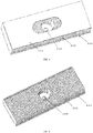
FIG. 2 is a schematic view of a heating device of an evaporator with an auxiliary heating device according to the present invention. -
FIG. 3 is a partial top view of a heating device of an evaporator with an auxiliary heating device according to the present invention. -
FIG. 4 is a schematic view of a radiator with a fixing sheet of an evaporator with an auxiliary heating device according to the present invention. -
FIG. 5 is a schematic view of a radiator without a fixing sheet of an evaporator with an auxiliary heating device according to the present invention. -
FIG. 6 is a schematic view of a heating body of an evaporator with an auxiliary heating device according to the present invention. -
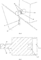
FIG. 7 is a schematic view of a first connection structure for a mounting plate and a mounting frame of an evaporator with an auxiliary heating device according to the present invention. -
FIG. 8 is a schematic view of the structure inFIG. 7 in a detached state. -
FIG. 9 is a sectional view of the mounting frame inFIG. 7 . -
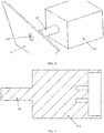
FIG. 10 is a schematic view of a second connection structure for a mounting plate and a mounting frame of an evaporator with an auxiliary heating device according to the present invention. -
FIG. 11 is a sectional view of the mounting frame inFIG. 10 . -
FIG. 12 is a schematic view of an air conditioner. - The present invention is described in further detail below with reference to the drawings and the embodiments, to enable a person skilled in the art to implement according to the text of the specification.
- It should be understood that the terms used herein, such as "have", "include" and "comprise" do not exclude existence or addition of one or more other element or combination thereof.
- As illustrated in
FIGS. 1 to 12 , the present invention provides an evaporator with an auxiliary heating device including anevaporator 1, aheating device 2, and twomounting plates 3. The twomounting plates 3 are provided at two ends of theevaporator 1 respectively, and two ends of theheating device 2 are connected to the twomounting plates 3 respectively. - Working principle of the above-described technical solution is: the two
mounting plates 3 are secured to the two ends of theevaporator 1 respectively, the material and the structure of the twomounting plates 3 are determined according to the practical requirements; themounting plate 3 and theevaporator 1 may employ a connection method such as welding, threaded connection, snap-fit connection, etc.; the two ends of theheating device 2 can be secured to themounting plates 3 through threaded connection, snap-fit connection, or other methods, and the two ends of theheating device 2 can be secured to themounting plate 3 by selecting different connection methods respectively; theheating device 2 employs PCT electric auxiliary heating technology, the PTC is a semiconductor heating ceramic, when the outside temperature decreases, the resistance value of the PTC decrease accordingly, but the generated heat increases accordingly; after theheating device 2 is energized, the electric energy is converted into the thermal energy to be transferred into the room. - Beneficial effects of the above-described technical solution are: when the outdoor temperature is below
minus 5 degrees, theheating device 2 is activated to heat and transfer the heat to the room, thus when the heating function of the air conditioner is used, it will not be limited by the outdoor temperature; moreover, icing, frosting or the like phenomena of theoutdoor unit 5 will not occur to affect the use of the air conditioner, the auxiliary heating device has a good heating effect and can achieve the purpose of rapid and powerful heating. - In one embodiment, the
heating device 2 includes a heating body 2-1, and a plurality of radiators 2-2, the plurality of radiators 2-2 is provided at upper and lower faces of the heating body 2-1, and two ends of theheating device 2 are symmetrically provided with mounting frames 2-3. - Working principle of the above-described technical solution is: the
heating device 2 has a cuboid structure as a whole, and the upper and lower faces of the heating body 2-1 have large area and emit more heat; the heating body 2-1 emits heat after being energized, and transfers the heat to the radiator 2-2, and the radiator 2-2 can effectively transfer the heat to the room; the number of the plurality of radiators 2-2 can be determined according to requirements, and the plurality of radiators 2-2 can be detachably connected to the heating body 2-1 through thread; two radiators 2-2 may be provided and symmetrically disposed at the upper and lower faces of the heating body 2-1, and there are at least three connection methods for them; the first is that the radiator 2-2 and the heating body 2-1 are integrally formed, the second is that a base of the radiator 2-2 is welded to the heating body 2-1, and the third is that an end of the radiator 2-2 and an end of the heating body 2-1 are fixed through the mounting frame 2-3, thereby connecting them. - Beneficial effects of the above-described technical solution are: the radiator 2-2 provided on the heating body 2-1 can transfer the heat generated by the heating body 2-1 to the room more rapidly, improving the heat transfer efficiency; there are various connection methods for the radiator 2-2 and the heating body 2-1, which can be selected according to practical requirements.
- In one embodiment, the heating body 2-1 and the plurality of radiators 2-2 are integrally formed.
- Working principle of the above-described technical solution is: two radiators 2-2 may be provided, the upper and lower faces of the heating body 2-1 is symmetrically provided with the radiators 2-2, and they can be integrally formed in the production process.
- Beneficial effects of the above-described technical solution are: the heating body 2-1 and the radiator 2-2 are integrally formed and can be used directly, saving the assembly time and having high heat conduction efficiency.
- In one embodiment, bottom faces of the plurality of radiators 2-2 are welded to the upper and lower faces of the heating body 2-1.
- Working principle of the above-described technical solution is: the number of the radiators 2-2 can be determined according to requirements, and two or more radiators may be provided; the radiator 2-2 is welded to the heating body 2-1, they are produced separately, and the heating body 2-1 can be welded with radiators 2-2 of different specifications.
- Beneficial effects of the above-described technical solution are: the welding is firm, and the heat conduction efficiency is high.
- In one embodiment, the upper and lower faces of the heating body 2-1 are symmetrically provided with the radiators 2-2, and an end of the heating body 2-1 and an end of the radiator 2-2 are fixedly connected through the mounting frame 2-3.
- Working principle of the above-described technical solution is: the number of the radiators 2-2 may be two, the length and width of the radiator 2-2 are both equal to the length and the width of the heating body 2-1, and they are symmetrically disposed at the upper and lower faces of the heating body 2-1; two ends of each of the two radiators 2-2 and the heating body 2-1 can be inserted into the first groove 2-3-1 of the mounting frame 2-3, and the two radiators 2-2 and the heating body 2-1 are fixedly connected by interference fit with the first groove 2-3-1, such that bottom faces of the radiators 2-2 are in complete contact with the heating body 2-1.
- Beneficial effects of the above-described technical solution are: the heating body 2-1 and the radiator 2-2 are connected only by the mounting frame 2-3, if the heating body 2-1 is damaged, the replacement thereof is very convenient; the specifications of the radiator 2-2 can be selected freely to combine with the heating body 2-1.
- In one embodiment, the radiator 2-2 includes a radiator base 2-2-1 and a plurality of first fins 2-2-2, the plurality of first fins 2-2-2 is distributed vertically and uniformly on the radiator base 2-2-1, and a width of the first fin 2-2-2 is equal to a width of the radiator base 2-2-1.
- Working principle of the above-described technical solution is: the overall structure of the radiator 2-2 is a cuboid, the radiator base 2-2-1 is fixedly connected to the upper face or the lower face of the heating body 2-1, the radiator base 2-2-1 is used to fix the plurality of first fins 2-2-2, and the radiator 2-2 can effectively absorb the heat from the heating body 2-1 through the plurality of first fins 2-2-2.
- Beneficial effects of the above-described technical solution are: the plurality of first fins 2-2-2 of the radiator 2-2 can rapidly absorb the heat generated by the heating body 2-1, and efficiently transfer the heat.
- In one embodiment, the radiator 2-2 is provided with a fixing sheet 2-2-3 for fixing the plurality of first fins 2-2-2, the fixing sheet 2-2-3 has a width equal to the width of the radiator base 2-2-1, and the fixing sheet 2-2-3 and the radiator base 2-2-1 are disposed parallel to each other.
- Working principle of the above-described technical solution is: the radiator 2-2 may also be provided with a fixing sheet 2-2-3 for fixing the first fins 2-2-2 according to requirements, thereby protecting the first fins 2-2-2 from damage to some extent.
- Beneficial effects of the above-described technical solution are: the fixing sheet 2-2-3 can make fixation of the first fins 2-2-2 more firm and can prevent the first fins 2-2-2 from deformation due to external forces to some extent, which otherwise affects the heat radiation effect.
- In one embodiment, a central position of the radiator base 2-2-1 is provided with a first round hole 2-2-4, and a central position of the fixing sheet 2-2-3 is provided with a first oblong hole 2-2-5 corresponding to the first round hole 2-2-4.
- It could be understood that, the expression "a first element corresponds to a second element" used herein means that the first element is able to be fitted with the second element. For example, the first oblong hole 2-2-3 corresponds to the first round hole 2-2-4, that is, the first oblong hole 2-2-3 is able to be fitted with the first round hole 2-2-4.
- Working principle of the above-described technical solution is: the first round hole 2-2-4 of the radiator base 2-2-1 is used to connect the heating body 2-1, a certain amount of mounting space is left around the first round hole 2-2-4, a center of the first oblong hole 2-2-5 and a center of the first round hole 2-2-4 coincide, and a size of the first oblong hole 2-2-5 is not smaller than a size of the mounting space left around the first round hole 2-2-4.
- Beneficial effects of the above-described technical solution are: the radiator 2-2 is detachably connected to the heating body 2-1 through the first round hole 2-2-4, the mounting space for the nut is left around the first round hole 2-2-4, and the fixing sheet 2-2-3 is provided with the first oblong hole 2-2-5, which all make the detachment of the radiator 2-2 more convenient.
- In one embodiment, a plurality of first studs 2-1-1 corresponding to the first round hole 2-2-4 are distributed on the upper and lower faces of the heating body 2-1.
- Working principle of the above-described technical solution is: the plurality of first studs 2-1-2 is uniformly distributed in the length direction of the heating body 2-1, and is used to mount the radiator 2-2; the first round hole 2-2-4 of the radiator base 2-2-1 allows the first stud 2-1-1 to pass through, and the nut is used to threaded onto the first stud 2-1-1, to lock the radiator 2-2, and make the radiator base 2-2-1 and the heating body 2-1 have sufficient contact and firm fixation.
- Beneficial effects of the above-described technical solution are: the radiator 2-2 can be secured to the heating body 2-1 firmly, such that they can be in sufficient contact to transfer the heat better.
- Preferably, at least an end of the heating body 2-1 is provided with a plug 2-1-2.
- Working principle of the above-described technical solution is: the plug 2-1-2 provided to the at least an end of the heating body 2-1 can be used to fix the
heating device 2. - Beneficial effects of the above-described technical solution are: the plug 2-1-2 is used to fix the
heating device 2 to the mounting frame 2-3, limiting the displacement of theheating device 2 to some extent. - In one embodiment, a width of the heating body 2-1 is equal to the width of the radiator base 2-2-1.
- Working principle of the above-described technical solution is: the heating body 2-1 and the plurality of radiators 2-2 form a complete
cuboid heating device 2, the heating body 2-1 has a width equal to that of the radiator base 2-2-1, thus the contact area therebetween is maximized, and the heat transfer efficiency is the highest. - Beneficial effects of the above-described technical solution are: the heating body 2-1 has a width equal to that of the radiator base 2-2-1, such that the contact area therebetween can be maximized; when the heating body 2-1 heats, the heat can transfer to the radiator 2-2 more efficiently, resulting in better heat output.
- In one embodiment, a side of the mounting frame 2-3 is provided with a first groove 2-3-1 allowing the end of the
heating device 2 to be inserted therein, the opposite side thereof is provided with a connection portion, and the first groove 2-3-1 is internally provided with a socket 2-3-2 corresponding to the plug 2-1-2. - Working principle of the above-described technical solution is: the
heating device 2 is packaged in the interior of theevaporator 1, and the mounting frames 2-3 provided at two ends of theheating device 2 are used to fix theheating device 2 in theevaporator 1; the first groove 2-3-1 allows the end of theheating device 2 to be inserted therein, and the socket 2-3-2 provided in the first groove 2-3-1 allows the plug 2-1-2 of the heating body 2-1 to be inserted and snap-fitted therein, to firmly connect theheating device 2 to the mounting frame 2-3; the connection portion provided to the mounting frame 2-3 is used to connect with the mountingplate 3, there are various connection methods for the mounting frame 2-3 and the mountingplate 3, such as combination of threaded connection, welding, snap-fit connection or the like. - Beneficial effects of the above-described technical solution are: the mounting frame 2-3 and the mounting
plate 3 can cooperate to firmly fix theheating device 2 in theevaporator 1, and the mounting frame 2-3 not only can fix theheating device 2 but also have an insulation effect; the various connection methods for the mounting frame 2-3 and the mountingplate 3 can combined and used freely according to the practical requirements. - In one embodiment, the connection portion includes a second stud a1, an end of the second stud a1 is connected to the mounting frame 2-3, and the mounting frame 2-3 is provided with a second round hole a2 corresponding to the second stud a1.
- Working principle of the above-described technical solution is: this is the first connection method for the mounting frame 2-3 and the mounting
plate 3, the second stud a1 of the mounting frame 2-3 can pass through the second round hole a2, and be locked on the mountingplate 3 by the nut. - Beneficial effects of the above-described technical solution are: the structure is simple, the mounting is convenient, and the fixation is firm.
- In one embodiment, the connection portion includes a connecting rod b1 and a snap-fitting part b2, an end of the connecting rod b1 is connected to the mounting frame 2-3, a middle portion and the other end of the connecting rod b1 are provided with the snap-fitting part b2 snap-fitted with the mounting
plate 3, a maximum diameter of the snap-fitting part b2 is smaller than a diameter of the connecting rod b1, and two symmetrical faces of the snap-fitting part b2 are each provided with a second groove b3; the mountingplate 3 is provided with an aperture b4 corresponding to the second groove b3, and a bottom end of the aperture b4 is provided with a third round hole b5 corresponding to the maximum diameter of the snap-fitting part b2. - Working principle of the above-described technical solution is: this is the second connection method for the mounting frame 2-3 and the mounting
plate 3, when mounting, the second groove b3 is aligned with the aperture b4 and inserted from top to bottom into the third round hole b5, and then the snap-fitting part b2 is rotated by 90 degrees, in this case, the maximum diameter arc of the snap-fitting part b2 and the third round hole b5 form interference fit, the great friction force therebetween limits the radial motion of the snap-fitting part b2; since the maximum diameter of the snap-fitting part b2 is smaller than the diameter of the connecting rod b1, in this case, the connecting rod b1 limits the axial motion of the snap-fitting part b2, and the mounting frame 2-3 is firmly fixed to the mountingplate 3. - Beneficial effects of the above-described technical solution are: by means of snap-fitting of the snap-fitting part b2 and the mounting
plate 3, the disassembly and assembly of the mounting frame 2-3 become very convenient, they can be firmly fixed only by an external force without a tool. - It should note that, the two fixing methods for the mounting frame 2-3 and the mounting
plate 3 can be combined and used according to practical situations, which is however not limited to the two fixing methods. - In one embodiment, the
evaporator 1 includes a plurality of second fins 1-1 and a copper tube 1-2, the second fin 1-1 is substantively C-shaped, the plurality of second fins 1-1 is parallel to each other and distributed uniformly, and the copper tuber 1-2 is continuously bent into a U shape, passes through the plurality of second fins 1-1 and is fixedly connected to the plurality of second fins 1-1. - Working principle of the above-described technical solution is: the copper tube 1-2 is used to pass the liquid or gaseous Freon, and the plurality of second fins 1-1 are tightly connected to the copper tube, such that the temperature of the copper tube 1-2 can be efficiently transferred to the plurality of second fins 1-1, and then appropriate temperature is transferred to the room.
- Beneficial effects of the above-described technical solution are: the copper tube 1-2 has excellent heat conduction performance, and the second fins 1-1 are mainly used to emit the heat from the copper tube 1-2 out and efficiently transfer the appropriate temperature to the room.
- The present disclosure further provides an air conditioner, including an
outdoor unit 5; and anindoor unit 4 in communication with theoutdoor unit 5 and including an above-described evaporator with the auxiliary heating device. - Working principle of the above-described technical solution is: the air conditioner includes an outdoor unit 5 and an indoor unit 4, the outdoor unit 5 and the indoor unit 4 are communicated through the high-pressure tube 6 and the gas return tube 7; the outdoor unit 5 is internally provided with a compressor, and a condensor; the indoor unit 4 is internally provided with an evaporator 1 and a cross flow fan; when the air conditioner employing an evaporator 1 without the auxiliary heating device performs heating, its heating principle is that the compressor in the outdoor unit 5 compresses Freon into a high-temperature and high-pressure gas, which enters the copper tube 1-2 of the evaporator 1 of the indoor unit 4 through the high-pressure tube 6, the gaseous Freon in the high-temperature and high-pressure state encounters the low-temperature copper tube 1-2, condenses into a liquid Freon, and release heat to rise the temperature of the air in the indoor unit 4; the heated air is transferred to the room by the cross flow fan, thereby forming warm airflow; the liquid Freon will continue to flow along the copper tube 1-2 in the indoor unit 4 back to the outdoor unit 5, the liquid Freon absorbs the heat of the outdoor air in the outdoor unit 5 through the condensor, becomes gaseous Freon, and flows back to the compressor, thus completing one cycle and starting next one; if the outdoor temperature is below minus 5 degrees, the heating effect of the air conditioner will be greatly affected, such that the icing, frosting or other phenomena of the outdoor unit 5 of the air conditioner are prone to occur, in which case the outdoor unit 5 needs to perform defrosting continuously, resulting in slow heat supply and low heat power, and even more the air conditioner cannot perform heating; therefore, adding the auxiliary heating device into the evaporator 1 can effectively improve the heating efficiency of the air conditioner, and ensure that the air conditioner can effectively perform heating at any outdoor temperature.
- Beneficial effects of the above-described technical solution are: the air conditioner having an
evaporator 1 with the auxiliary heating device can heat at a low temperature and transfer the heat to the room, without being affected by the outside temperature, and will not cause occurrence of the icing, frosting, or other phenomena of theoutdoor unit 5 which otherwise will affect the use of the air conditioner. - In the specification, it is to be understood that terms such as "central," "longitudinal," "lateral," "length," "width," "thickness," "upper," "lower," "front," "rear," "left," "right," "vertical," "horizontal," "top," "bottom," "inner," "outer," "clockwise," "counterclockwise," "axial," "radial" and "circumferential" should be construed to refer to the orientation as then described or as shown in the drawings under discussion. These relative terms are for convenience of description and do not require that the present disclosure be constructed or operated in a particular orientation.
- In the present disclosure, unless specified or limited otherwise, the terms "mounted," "connected," "coupled," "fixed" and the like are used broadly, and may be, for example, fixed connections, detachable connections, or integral connections; may also be mechanical or electrical connections; may also be direct connections or indirect connections via intervening structures; may also be inner communications of two elements, unless limited otherwise. These having ordinary skills in the art should understand the specific meanings in the present disclosure according to specific situations.
- Although implementations of the present invention are disclosed as above, but are not merely limited to applications listed in the specification and the embodiments, and they are absolutely applicable to various fields suitable for the present invention. For a person skilled in the art, additional modifications can be readily achieved, therefore, the present invention is not limited to the specified details and the drawings illustrated and described herein, without departing from the general concepts defined by the claims and their equivalent scope.
Claims (15)
- An evaporator with an auxiliary heating device, comprising:an evaporator (1),a heating device (2), andtwo mounting plates (3) provided at two ends of the evaporator (1) respectively,wherein two ends of the heating device (2) are connected to the two mounting plates (3) respectively.
- The evaporator with the auxiliary heating device according to claim 1, wherein the heating device (2) includes a heating body (2-1), and a plurality of radiators (2-2), the plurality of radiators (2-2) is provided at upper and lower faces of the heating body (2-1), and two ends of the heating device (2) are symmetrically provided with mounting frames (2-3).
- The evaporator with the auxiliary heating device according to claim 2, wherein the heating body (2-1) and the plurality of radiators (2-2) are integrally formed.
- The evaporator with the auxiliary heating device according to claim 2 or 3, wherein bottom faces of the plurality of radiators (2-2) are welded to the upper and lower faces of the heating body (2-1).
- The evaporator with the auxiliary heating device according to any one of claims 2 to 4, wherein the upper and lower faces of the heating body (2-1) are symmetrically provided with the radiators (2-2), an end of the heating body (2-1) and an end of the radiator (2-2) are fixedly connected through the mounting frame (2-3).
- The evaporator with the auxiliary heating device according to any one of claims 2 to 5, wherein the radiator (2-2) comprises a radiator base (2-2-1) and a plurality of first fins (2-2-2), the plurality of first fins (2-2-2) is distributed vertically and uniformly on the radiator base (2-2-1), and a width of the first fin (2-2-2) is equal to a width of the radiator base (2-2-1).
- The evaporator with the auxiliary heating device according to claim 6, wherein the radiator (2-2) is provided with a fixing sheet (2-2-3) for fixing the plurality of first fins (2-2-2), the fixing sheet (2-2-3) has a width equal to the width of the radiator base (2-2-1), and the fixing sheet (2-2-3) and the radiator base (2-2-1) are disposed parallel to each other.
- The evaporator with the auxiliary heating device according to claim 7, wherein a central position of the radiator base (2-2-1) is provided with a first round hole (2-2-4), and a central position of the fixing sheet (2-2-3) is provided with a first oblong hole (2-2-5) corresponding to the first round hole (2-2-4).
- The evaporator with the auxiliary heating device according to claim 8, wherein a plurality of first studs (2-1-1) corresponding to the first round hole (2-2-4) are distributed on the upper and lower faces of the heating body (2-1); preferably, at least an end of the heating body (2-1) is provided with a plug (2-1-2).
- The evaporator with the auxiliary heating device according to any one of claims 6 to 9, wherein the heating body (2-1) has a width equal to the width of the radiator base (2-2-1).
- The evaporator with the auxiliary heating device according to claim 9 or 10, wherein a side of the mounting frame (2-3) is provided with a first groove (2-3-1) allowing the end of the heating device (2) to be inserted therein, the opposite side thereof is provided with a connection portion, and the first groove (2-3-1) is internally provided with a socket (2-3-2) corresponding to the plug (2-1-2).
- The evaporator with the auxiliary heating device according to claim 11, wherein the connection portion comprises a second stud (a1), an end of the second stud (a1) is connected to the mounting frame (2-3), and the mounting frame (2-3) is provided with a second round hole (a2) corresponding to the second stud (a1).
- The evaporator with the auxiliary heating device according to claim 11 or 12, wherein the connection portion comprises a connecting rod (b1) and a snap-fitting part (b2), an end of the connecting rod (b1) is connected to the mounting frame (2-3), a middle portion and the other end of the connecting rod (b1) are provided with the snap-fitting part (b2) snap-fitted with the mounting plate (3), a maximum diameter of the snap-fitting part (b2) is smaller than a diameter of the connecting rod (b1), and two symmetrical faces of the snap-fitting part (b2) are each provided with a second groove (b3); the mounting plate (3) is provided with an aperture (b4) corresponding to the second groove (b3), and a bottom end of the aperture (b4) is provided with a third round hole (b5) corresponding to the maximum diameter of the snap-fitting part (b2).
- The evaporator with the auxiliary heating device according to any one of claims 1 to 13, wherein the evaporator (1) comprises a plurality of second fins (1-1) and a copper tube (1-2), the second fin (1-1) is substantively C-shaped, the plurality of second fins (1-1) is parallel to each other and distributed uniformly, and the copper tuber (1-2) is continuously bent into a U shape, passes through the plurality of second fins (1-1) and is fixedly connected to the plurality of second fins (1-1).
- An air conditioner, comprising:an outdoor unit (5); andan indoor unit (4) in communication with the outdoor unit (5) and comprising an evaporator with an auxiliary heating device according to any one of claims 1 to 14.
Applications Claiming Priority (1)
| Application Number | Priority Date | Filing Date | Title |
|---|---|---|---|
| CN202021315357.6U CN211526773U (en) | 2020-07-07 | 2020-07-07 | Evaporator with auxiliary heating device and air conditioner |
Publications (2)
| Publication Number | Publication Date |
|---|---|
| EP3936792A1 true EP3936792A1 (en) | 2022-01-12 |
| EP3936792B1 EP3936792B1 (en) | 2025-03-26 |
Family
ID=72441693
Family Applications (1)
| Application Number | Title | Priority Date | Filing Date |
|---|---|---|---|
| EP20202239.8A Active EP3936792B1 (en) | 2020-07-07 | 2020-10-16 | Evaporator with auxiliary heating device and air conditioner |
Country Status (3)
| Country | Link |
|---|---|
| EP (1) | EP3936792B1 (en) |
| CN (1) | CN211526773U (en) |
| ES (1) | ES3021507T3 (en) |
Citations (4)
| Publication number | Priority date | Publication date | Assignee | Title |
|---|---|---|---|---|
| JPH03225174A (en) * | 1990-01-31 | 1991-10-04 | Sanyo Electric Co Ltd | Ceiling-suspended cooling device |
| CN104540252A (en) * | 2014-12-11 | 2015-04-22 | 广东志高空调有限公司 | PTC electric heating device |
| CN107990411A (en) * | 2017-11-21 | 2018-05-04 | 珠海格力电器股份有限公司 | Indoor unit and air conditioner using same |
| CN208886927U (en) * | 2018-08-21 | 2019-05-21 | 宁波奥克斯电气股份有限公司 | A kind of electric heating mounting structure and air conditioner |
-
2020
- 2020-07-07 CN CN202021315357.6U patent/CN211526773U/en active Active
- 2020-10-16 EP EP20202239.8A patent/EP3936792B1/en active Active
- 2020-10-16 ES ES20202239T patent/ES3021507T3/en active Active
Patent Citations (4)
| Publication number | Priority date | Publication date | Assignee | Title |
|---|---|---|---|---|
| JPH03225174A (en) * | 1990-01-31 | 1991-10-04 | Sanyo Electric Co Ltd | Ceiling-suspended cooling device |
| CN104540252A (en) * | 2014-12-11 | 2015-04-22 | 广东志高空调有限公司 | PTC electric heating device |
| CN107990411A (en) * | 2017-11-21 | 2018-05-04 | 珠海格力电器股份有限公司 | Indoor unit and air conditioner using same |
| CN208886927U (en) * | 2018-08-21 | 2019-05-21 | 宁波奥克斯电气股份有限公司 | A kind of electric heating mounting structure and air conditioner |
Also Published As
| Publication number | Publication date |
|---|---|
| CN211526773U (en) | 2020-09-18 |
| ES3021507T3 (en) | 2025-05-27 |
| EP3936792B1 (en) | 2025-03-26 |
Similar Documents
| Publication | Publication Date | Title |
|---|---|---|
| CN204612090U (en) | A kind of air conditioner utilizing heat of compressor to carry out thermo-electric generation | |
| CN101999063B (en) | Air conditioner | |
| JP2003240256A (en) | Air conditioner using thermoelectric module | |
| CN109959182B (en) | Refrigeration systems and air conditioners | |
| CN104214922A (en) | Equipment cabinet air adjusting device and equipment cabinet air adjusting device case | |
| CN106958962A (en) | Semiconductor defrosting heater and refrigeration plant | |
| EP3936792A1 (en) | Evaporator with auxiliary heating device and air conditioner | |
| CN109959181B (en) | Refrigeration systems and air conditioners | |
| CN216673674U (en) | Automatically controlled board heat radiation structure and heat pump water heater | |
| CN116294246B (en) | Insulated box based on the integrated utilization of solar photovoltaic thermal and semiconductor heating | |
| CN202074608U (en) | Vacuum superconductive inner and outer fin laminated multidirectional air-out electrothermal unit heater | |
| CN216522475U (en) | Refrigerant cooling system and air conditioner | |
| CN217686428U (en) | PO membrane heat pump source oven | |
| CN216347154U (en) | Inside and outside dual cycle semiconductor cold-storage warm-storage box | |
| CN117856071A (en) | A pre-installed substation and photovoltaic power generation system | |
| CN211909463U (en) | Heat exchange structure of frequency converter | |
| CN107166692A (en) | Air-conditioning system | |
| CN211041477U (en) | Heat exchanger for strengthening heat transfer of thermoelectric material | |
| CN220506999U (en) | Evaporator for air conditioner and air conditioner indoor unit | |
| CN206831775U (en) | Casing assembly, heating component and the air conditioner of heating component | |
| CN205678858U (en) | A kind of heat-exchanger rig and the semiconductor air-conditioner with this heat-exchanger rig | |
| CN217178753U (en) | Outdoor machine of air conditioner | |
| CN203286734U (en) | Cabinet air conditioning device and cabinet air conditioning device shell | |
| CN223843910U (en) | PTC heater structure | |
| CN217004964U (en) | Modular air-cooled heat pump unit capable of simultaneously supplying cold and heat |
Legal Events
| Date | Code | Title | Description |
|---|---|---|---|
| PUAI | Public reference made under article 153(3) epc to a published international application that has entered the european phase |
Free format text: ORIGINAL CODE: 0009012 |
|
| STAA | Information on the status of an ep patent application or granted ep patent |
Free format text: STATUS: REQUEST FOR EXAMINATION WAS MADE |
|
| 17P | Request for examination filed |
Effective date: 20210915 |
|
| AK | Designated contracting states |
Kind code of ref document: A1 Designated state(s): AL AT BE BG CH CY CZ DE DK EE ES FI FR GB GR HR HU IE IS IT LI LT LU LV MC MK MT NL NO PL PT RO RS SE SI SK SM TR |
|
| B565 | Issuance of search results under rule 164(2) epc |
Effective date: 20210323 |
|
| GRAP | Despatch of communication of intention to grant a patent |
Free format text: ORIGINAL CODE: EPIDOSNIGR1 |
|
| STAA | Information on the status of an ep patent application or granted ep patent |
Free format text: STATUS: GRANT OF PATENT IS INTENDED |
|
| INTG | Intention to grant announced |
Effective date: 20241114 |
|
| GRAS | Grant fee paid |
Free format text: ORIGINAL CODE: EPIDOSNIGR3 |
|
| P01 | Opt-out of the competence of the unified patent court (upc) registered |
Free format text: CASE NUMBER: APP_1943/2025 Effective date: 20250113 |
|
| GRAA | (expected) grant |
Free format text: ORIGINAL CODE: 0009210 |
|
| STAA | Information on the status of an ep patent application or granted ep patent |
Free format text: STATUS: THE PATENT HAS BEEN GRANTED |
|
| AK | Designated contracting states |
Kind code of ref document: B1 Designated state(s): AL AT BE BG CH CY CZ DE DK EE ES FI FR GB GR HR HU IE IS IT LI LT LU LV MC MK MT NL NO PL PT RO RS SE SI SK SM TR |
|
| REG | Reference to a national code |
Ref country code: GB Ref legal event code: FG4D |
|
| REG | Reference to a national code |
Ref country code: CH Ref legal event code: EP |
|
| REG | Reference to a national code |
Ref country code: DE Ref legal event code: R096 Ref document number: 602020048238 Country of ref document: DE |
|
| REG | Reference to a national code |
Ref country code: IE Ref legal event code: FG4D |
|
| REG | Reference to a national code |
Ref country code: NL Ref legal event code: FP |
|
| REG | Reference to a national code |
Ref country code: ES Ref legal event code: FG2A Ref document number: 3021507 Country of ref document: ES Kind code of ref document: T3 Effective date: 20250527 |
|
| PG25 | Lapsed in a contracting state [announced via postgrant information from national office to epo] |
Ref country code: RS Free format text: LAPSE BECAUSE OF FAILURE TO SUBMIT A TRANSLATION OF THE DESCRIPTION OR TO PAY THE FEE WITHIN THE PRESCRIBED TIME-LIMIT Effective date: 20250626 |
|
| PG25 | Lapsed in a contracting state [announced via postgrant information from national office to epo] |
Ref country code: FI Free format text: LAPSE BECAUSE OF FAILURE TO SUBMIT A TRANSLATION OF THE DESCRIPTION OR TO PAY THE FEE WITHIN THE PRESCRIBED TIME-LIMIT Effective date: 20250326 |
|
| REG | Reference to a national code |
Ref country code: LT Ref legal event code: MG9D |
|
| PG25 | Lapsed in a contracting state [announced via postgrant information from national office to epo] |
Ref country code: NO Free format text: LAPSE BECAUSE OF FAILURE TO SUBMIT A TRANSLATION OF THE DESCRIPTION OR TO PAY THE FEE WITHIN THE PRESCRIBED TIME-LIMIT Effective date: 20250626 |
|
| PG25 | Lapsed in a contracting state [announced via postgrant information from national office to epo] |
Ref country code: HR Free format text: LAPSE BECAUSE OF FAILURE TO SUBMIT A TRANSLATION OF THE DESCRIPTION OR TO PAY THE FEE WITHIN THE PRESCRIBED TIME-LIMIT Effective date: 20250326 |
|
| PG25 | Lapsed in a contracting state [announced via postgrant information from national office to epo] |
Ref country code: LV Free format text: LAPSE BECAUSE OF FAILURE TO SUBMIT A TRANSLATION OF THE DESCRIPTION OR TO PAY THE FEE WITHIN THE PRESCRIBED TIME-LIMIT Effective date: 20250326 |
|
| PG25 | Lapsed in a contracting state [announced via postgrant information from national office to epo] |
Ref country code: GR Free format text: LAPSE BECAUSE OF FAILURE TO SUBMIT A TRANSLATION OF THE DESCRIPTION OR TO PAY THE FEE WITHIN THE PRESCRIBED TIME-LIMIT Effective date: 20250627 Ref country code: BG Free format text: LAPSE BECAUSE OF FAILURE TO SUBMIT A TRANSLATION OF THE DESCRIPTION OR TO PAY THE FEE WITHIN THE PRESCRIBED TIME-LIMIT Effective date: 20250326 |
|
| PG25 | Lapsed in a contracting state [announced via postgrant information from national office to epo] |
Ref country code: SE Free format text: LAPSE BECAUSE OF FAILURE TO SUBMIT A TRANSLATION OF THE DESCRIPTION OR TO PAY THE FEE WITHIN THE PRESCRIBED TIME-LIMIT Effective date: 20250326 |
|
| REG | Reference to a national code |
Ref country code: AT Ref legal event code: MK05 Ref document number: 1779314 Country of ref document: AT Kind code of ref document: T Effective date: 20250326 |
|
| PG25 | Lapsed in a contracting state [announced via postgrant information from national office to epo] |
Ref country code: SM Free format text: LAPSE BECAUSE OF FAILURE TO SUBMIT A TRANSLATION OF THE DESCRIPTION OR TO PAY THE FEE WITHIN THE PRESCRIBED TIME-LIMIT Effective date: 20250326 |
|
| PG25 | Lapsed in a contracting state [announced via postgrant information from national office to epo] |
Ref country code: PT Free format text: LAPSE BECAUSE OF FAILURE TO SUBMIT A TRANSLATION OF THE DESCRIPTION OR TO PAY THE FEE WITHIN THE PRESCRIBED TIME-LIMIT Effective date: 20250728 |
|
| PG25 | Lapsed in a contracting state [announced via postgrant information from national office to epo] |
Ref country code: PL Free format text: LAPSE BECAUSE OF FAILURE TO SUBMIT A TRANSLATION OF THE DESCRIPTION OR TO PAY THE FEE WITHIN THE PRESCRIBED TIME-LIMIT Effective date: 20250326 |
|
| PG25 | Lapsed in a contracting state [announced via postgrant information from national office to epo] |
Ref country code: AT Free format text: LAPSE BECAUSE OF FAILURE TO SUBMIT A TRANSLATION OF THE DESCRIPTION OR TO PAY THE FEE WITHIN THE PRESCRIBED TIME-LIMIT Effective date: 20250326 |
|
| PG25 | Lapsed in a contracting state [announced via postgrant information from national office to epo] |
Ref country code: EE Free format text: LAPSE BECAUSE OF FAILURE TO SUBMIT A TRANSLATION OF THE DESCRIPTION OR TO PAY THE FEE WITHIN THE PRESCRIBED TIME-LIMIT Effective date: 20250326 |
|
| PG25 | Lapsed in a contracting state [announced via postgrant information from national office to epo] |
Ref country code: RO Free format text: LAPSE BECAUSE OF FAILURE TO SUBMIT A TRANSLATION OF THE DESCRIPTION OR TO PAY THE FEE WITHIN THE PRESCRIBED TIME-LIMIT Effective date: 20250326 |
|
| PG25 | Lapsed in a contracting state [announced via postgrant information from national office to epo] |
Ref country code: SK Free format text: LAPSE BECAUSE OF FAILURE TO SUBMIT A TRANSLATION OF THE DESCRIPTION OR TO PAY THE FEE WITHIN THE PRESCRIBED TIME-LIMIT Effective date: 20250326 |
|
| PG25 | Lapsed in a contracting state [announced via postgrant information from national office to epo] |
Ref country code: IS Free format text: LAPSE BECAUSE OF FAILURE TO SUBMIT A TRANSLATION OF THE DESCRIPTION OR TO PAY THE FEE WITHIN THE PRESCRIBED TIME-LIMIT Effective date: 20250726 |
|
| PGFP | Annual fee paid to national office [announced via postgrant information from national office to epo] |
Ref country code: NL Payment date: 20251021 Year of fee payment: 6 |
|
| REG | Reference to a national code |
Ref country code: DE Ref legal event code: R097 Ref document number: 602020048238 Country of ref document: DE |
|
| PGFP | Annual fee paid to national office [announced via postgrant information from national office to epo] |
Ref country code: DE Payment date: 20251021 Year of fee payment: 6 |
|
| PGFP | Annual fee paid to national office [announced via postgrant information from national office to epo] |
Ref country code: GB Payment date: 20251022 Year of fee payment: 6 |
|
| PG25 | Lapsed in a contracting state [announced via postgrant information from national office to epo] |
Ref country code: DK Free format text: LAPSE BECAUSE OF FAILURE TO SUBMIT A TRANSLATION OF THE DESCRIPTION OR TO PAY THE FEE WITHIN THE PRESCRIBED TIME-LIMIT Effective date: 20250326 |
|
| PGFP | Annual fee paid to national office [announced via postgrant information from national office to epo] |
Ref country code: IT Payment date: 20251024 Year of fee payment: 6 |
|
| PGFP | Annual fee paid to national office [announced via postgrant information from national office to epo] |
Ref country code: FR Payment date: 20251030 Year of fee payment: 6 |
|
| PG25 | Lapsed in a contracting state [announced via postgrant information from national office to epo] |
Ref country code: CZ Free format text: LAPSE BECAUSE OF FAILURE TO SUBMIT A TRANSLATION OF THE DESCRIPTION OR TO PAY THE FEE WITHIN THE PRESCRIBED TIME-LIMIT Effective date: 20250326 |
|
| PGFP | Annual fee paid to national office [announced via postgrant information from national office to epo] |
Ref country code: ES Payment date: 20251216 Year of fee payment: 6 |
|
| PLBE | No opposition filed within time limit |
Free format text: ORIGINAL CODE: 0009261 |
|
| STAA | Information on the status of an ep patent application or granted ep patent |
Free format text: STATUS: NO OPPOSITION FILED WITHIN TIME LIMIT |
|
| REG | Reference to a national code |
Ref country code: CH Ref legal event code: L10 Free format text: ST27 STATUS EVENT CODE: U-0-0-L10-L00 (AS PROVIDED BY THE NATIONAL OFFICE) Effective date: 20260211 |
|
| 26N | No opposition filed |
Effective date: 20260105 |