EP3936720A1 - Pump valve all-in-one machine for pneumatic lumbar support of car seat - Google Patents
Pump valve all-in-one machine for pneumatic lumbar support of car seat Download PDFInfo
- Publication number
- EP3936720A1 EP3936720A1 EP20784995.1A EP20784995A EP3936720A1 EP 3936720 A1 EP3936720 A1 EP 3936720A1 EP 20784995 A EP20784995 A EP 20784995A EP 3936720 A1 EP3936720 A1 EP 3936720A1
- Authority
- EP
- European Patent Office
- Prior art keywords
- valve
- air
- pump
- electromagnetic
- air valve
- Prior art date
- Legal status (The legal status is an assumption and is not a legal conclusion. Google has not performed a legal analysis and makes no representation as to the accuracy of the status listed.)
- Granted
Links
Images



Classifications
-
- F—MECHANICAL ENGINEERING; LIGHTING; HEATING; WEAPONS; BLASTING
- F04—POSITIVE - DISPLACEMENT MACHINES FOR LIQUIDS; PUMPS FOR LIQUIDS OR ELASTIC FLUIDS
- F04B—POSITIVE-DISPLACEMENT MACHINES FOR LIQUIDS; PUMPS
- F04B43/00—Machines, pumps, or pumping installations having flexible working members
- F04B43/02—Machines, pumps, or pumping installations having flexible working members having plate-like flexible members, e.g. diaphragms
-
- B—PERFORMING OPERATIONS; TRANSPORTING
- B60—VEHICLES IN GENERAL
- B60N—SEATS SPECIALLY ADAPTED FOR VEHICLES; VEHICLE PASSENGER ACCOMMODATION NOT OTHERWISE PROVIDED FOR
- B60N2/00—Seats specially adapted for vehicles; Arrangement or mounting of seats in vehicles
- B60N2/64—Back-rests or cushions
- B60N2/66—Lumbar supports
- B60N2/665—Lumbar supports using inflatable bladders
-
- F—MECHANICAL ENGINEERING; LIGHTING; HEATING; WEAPONS; BLASTING
- F04—POSITIVE - DISPLACEMENT MACHINES FOR LIQUIDS; PUMPS FOR LIQUIDS OR ELASTIC FLUIDS
- F04B—POSITIVE-DISPLACEMENT MACHINES FOR LIQUIDS; PUMPS
- F04B39/00—Component parts, details, or accessories, of pumps or pumping systems specially adapted for elastic fluids, not otherwise provided for in, or of interest apart from, groups F04B25/00 - F04B37/00
- F04B39/0027—Pulsation and noise damping means
-
- F—MECHANICAL ENGINEERING; LIGHTING; HEATING; WEAPONS; BLASTING
- F04—POSITIVE - DISPLACEMENT MACHINES FOR LIQUIDS; PUMPS FOR LIQUIDS OR ELASTIC FLUIDS
- F04B—POSITIVE-DISPLACEMENT MACHINES FOR LIQUIDS; PUMPS
- F04B39/00—Component parts, details, or accessories, of pumps or pumping systems specially adapted for elastic fluids, not otherwise provided for in, or of interest apart from, groups F04B25/00 - F04B37/00
- F04B39/10—Adaptations or arrangements of distribution members
-
- F—MECHANICAL ENGINEERING; LIGHTING; HEATING; WEAPONS; BLASTING
- F04—POSITIVE - DISPLACEMENT MACHINES FOR LIQUIDS; PUMPS FOR LIQUIDS OR ELASTIC FLUIDS
- F04B—POSITIVE-DISPLACEMENT MACHINES FOR LIQUIDS; PUMPS
- F04B45/00—Pumps or pumping installations having flexible working members and specially adapted for elastic fluids
- F04B45/04—Pumps or pumping installations having flexible working members and specially adapted for elastic fluids having plate-like flexible members, e.g. diaphragms
-
- F—MECHANICAL ENGINEERING; LIGHTING; HEATING; WEAPONS; BLASTING
- F04—POSITIVE - DISPLACEMENT MACHINES FOR LIQUIDS; PUMPS FOR LIQUIDS OR ELASTIC FLUIDS
- F04B—POSITIVE-DISPLACEMENT MACHINES FOR LIQUIDS; PUMPS
- F04B49/00—Control, e.g. of pump delivery, or pump pressure of, or safety measures for, machines, pumps, or pumping installations, not otherwise provided for, or of interest apart from, groups F04B1/00 - F04B47/00
- F04B49/22—Control, e.g. of pump delivery, or pump pressure of, or safety measures for, machines, pumps, or pumping installations, not otherwise provided for, or of interest apart from, groups F04B1/00 - F04B47/00 by means of valves
-
- F—MECHANICAL ENGINEERING; LIGHTING; HEATING; WEAPONS; BLASTING
- F04—POSITIVE - DISPLACEMENT MACHINES FOR LIQUIDS; PUMPS FOR LIQUIDS OR ELASTIC FLUIDS
- F04B—POSITIVE-DISPLACEMENT MACHINES FOR LIQUIDS; PUMPS
- F04B49/00—Control, e.g. of pump delivery, or pump pressure of, or safety measures for, machines, pumps, or pumping installations, not otherwise provided for, or of interest apart from, groups F04B1/00 - F04B47/00
- F04B49/22—Control, e.g. of pump delivery, or pump pressure of, or safety measures for, machines, pumps, or pumping installations, not otherwise provided for, or of interest apart from, groups F04B1/00 - F04B47/00 by means of valves
- F04B49/225—Control, e.g. of pump delivery, or pump pressure of, or safety measures for, machines, pumps, or pumping installations, not otherwise provided for, or of interest apart from, groups F04B1/00 - F04B47/00 by means of valves with throttling valves or valves varying the pump inlet opening or the outlet opening
-
- F—MECHANICAL ENGINEERING; LIGHTING; HEATING; WEAPONS; BLASTING
- F04—POSITIVE - DISPLACEMENT MACHINES FOR LIQUIDS; PUMPS FOR LIQUIDS OR ELASTIC FLUIDS
- F04B—POSITIVE-DISPLACEMENT MACHINES FOR LIQUIDS; PUMPS
- F04B39/00—Component parts, details, or accessories, of pumps or pumping systems specially adapted for elastic fluids, not otherwise provided for in, or of interest apart from, groups F04B25/00 - F04B37/00
- F04B39/08—Actuation of distribution members
Definitions
- a lumbar support In order to reduce the fatigue caused by long-term driving, a lumbar support is usually disposed on the automobile seat.
- a manual lumbar support In order to reduce the fatigue caused by long-term driving, a lumbar support is usually disposed on the automobile seat.
- a manual lumbar support In present, there are three types of lumbar supports disposed on the automobile seat on the market, namely a manual lumbar support, an electric lumbar support and a pneumatic lumbar support, respectively.
- the manual lumbar support needs to be operated manually, and large operating torque, which often causes users to feel inconvenient and laborious; the electric lumbar support has a complex structure, many parts, high costs, and poor reliability; therefore, the pneumatic lumbar support is an ideal choice in the entire market.
- the Chinese patent CN 208010548 U discloses a "pump-valve integrated miniature air pump with a normally open electromagnetic air valve", and in the air pump, the air pump upper cover is designed into a cylindrical cavity, which is matched and connected with the two-position two-way normally open electromagnetic air valve, so that the upper cover of the pump forms such a structure that the top and bottom thereof are connected respectively with the two-position two-way normally open electromagnetic air valve and the air pump, achieving the pump-valve integrated structure, reducing the gas pipeline and reducing the occurrence of undesirable phenomena such as gas leakage.
- the structure has too single performance and few functions, and it is impossible to simultaneously inflate and deflate multiple products when using the air pump.
- An object of this application is to provide a pump-valve integrated machine for a pneumatic lumbar support of an automobile seat with reasonable structure, good performance, high reliability and low cost, so as to solve the technical problems of the existing pump-valve integrated machine that has a single performance and cannot achieve to simultaneously inflate and deflate multiple air bags.
Landscapes
- Engineering & Computer Science (AREA)
- Mechanical Engineering (AREA)
- General Engineering & Computer Science (AREA)
- Aviation & Aerospace Engineering (AREA)
- Transportation (AREA)
- Seats For Vehicles (AREA)
- Compressor (AREA)
- Compressors, Vaccum Pumps And Other Relevant Systems (AREA)
- Magnetically Actuated Valves (AREA)
- Check Valves (AREA)
Abstract
Description
- This application claims priority to the
Chinese invention patent application No. 201910256177.0 - The present application belongs to the field of air pumps for a pneumatic lumbar support, and specifically relates to a pump-valve integrated machine for a pneumatic lumbar support of an automobile seat that integrates an air pump and an air valve.
- In recent years, with the strongly development of the country's automobile industry, China has become the third country after the United States and Japan with an annual output of more than 10 million vehicles, and has entered the ranks of 10 million vehicles. Moreover, with the increase of personal family income, automobiles are no longer just office and transportation tools for government agencies and enterprises. Automobiles have become the first choice for household consumption. In addition to higher requirements for automobile brand, safety and quality, people pay more attention to the comfort of driving, among which the comfort of the automobile seat is very important.
- In order to reduce the fatigue caused by long-term driving, a lumbar support is usually disposed on the automobile seat. At present, there are three types of lumbar supports disposed on the automobile seat on the market, namely a manual lumbar support, an electric lumbar support and a pneumatic lumbar support, respectively. However, the manual lumbar support needs to be operated manually, and large operating torque, which often causes users to feel inconvenient and laborious; the electric lumbar support has a complex structure, many parts, high costs, and poor reliability; therefore, the pneumatic lumbar support is an ideal choice in the entire market.
- The air pump and air valve used in the pneumatic lumbar support are the core components of the entire pneumatic lumbar support. For most of the existing pneumatic lumbar supports in the market, the air pump and the air valve are separated, namely, a separate air valve and a separate air pump are connected with each other by a gas circuit such as a pipeline. However, the separation of pump and valve has the following disadvantages: (1) two parts require more transportation, storage, and management costs than one part; (2) the pump and the valve need to be connected by a gas pipe before, which occupies large space and causes cost waste in assembly, tooling, and personnel; and (3) the coordination of multiple parts is also less reliable than a single part, and the gas pipeline is prone to defects such as gas leakage and falling off.
- The Chinese patent
CN 208010548 U discloses a "pump-valve integrated miniature air pump with a normally open electromagnetic air valve", and in the air pump, the air pump upper cover is designed into a cylindrical cavity, which is matched and connected with the two-position two-way normally open electromagnetic air valve, so that the upper cover of the pump forms such a structure that the top and bottom thereof are connected respectively with the two-position two-way normally open electromagnetic air valve and the air pump, achieving the pump-valve integrated structure, reducing the gas pipeline and reducing the occurrence of undesirable phenomena such as gas leakage. However, the structure has too single performance and few functions, and it is impossible to simultaneously inflate and deflate multiple products when using the air pump. - An object of this application is to provide a pump-valve integrated machine for a pneumatic lumbar support of an automobile seat with reasonable structure, good performance, high reliability and low cost, so as to solve the technical problems of the existing pump-valve integrated machine that has a single performance and cannot achieve to simultaneously inflate and deflate multiple air bags.
- In order to achieve the above-mentioned object, the present application is achieved by adopting the following technical solutions:
a pump-valve integrated machine for a pneumatic lumbar support of an automobile seat including: an air pump, a pump valve connection base, an electromagnetic air valve lower base, a normally open electromagnetic air valve, an electromagnetic air valve upper cover, and a control circuit board, where a one-way air outlet structure is processed on the pump valve connection base, and the one-way air outlet structure on the pump valve connection base is opposite to and in communication with an air outlet hole of the air pump; the electromagnetic air valve lower base is fixed onto the air pump, and a mounting groove is processed on a bottom of the electromagnetic air valve lower base, and the pump valve connection base is provided within the mounting groove, a ventilation hole is processed on the electromagnetic air valve lower base opposite to the one-way air outlet structure of the pump valve connection base; the normally open electromagnetic air valve is disposed on the electromagnetic air valve lower base, an air inlet end of the normally open electromagnetic air valve corresponds to the ventilation hole of the electromagnetic air valve lower base; the electromagnetic air valve upper cover is provided above the normally open electromagnetic air valve, and an air outlet connector of the electromagnetic air valve upper cover corresponds to a valve core of the normally open electromagnetic air valve, the normally open electromagnetic air valve is open when it is not powered on, and gas of the air pump is discharged from the air outlet connector through the normally open electromagnetic air valve, and when the normally open electromagnetic air valve is powered on, the gas of the air pump cannot be discharged from the air outlet connector through the normally open electromagnetic air valve; and the control circuit board is configured to control operations of the electromagnetic air valve and the air pump. - As a preferred embodiment of the present application, the pump-valve integrated machine further includes a housing disposed on the air pump, and the electromagnetic air valve lower base, the normally open electromagnetic air valve, and the electromagnetic air valve upper cover are all disposed in the housing.
- As a preferred embodiment of the present application, the pump-valve integrated machine further includes a pressure sensor, and a mounting hole for the pressure sensor is processed on a side wall of the electromagnetic air valve lower base. The mounting hole for the pressure sensor communicates with the ventilation hole, and a connection pipe is disposed outside the mounting hole for the pressure sensor, and the connection pipe is connected with the pressure sensor, to transmit a pressure signal to the pressure sensor. The pressure sensor and the control circuit board are electrically connected.
- As a further preferred embodiment of the present application, the pump valve connection base includes a rubber sheet bracket and a one-way rubber sheet. A connection protrusion is processed on a bottom of the rubber sheet bracket, and the connection protrusion is disposed on the air outlet hole of the air pump. A mounting groove is processed around the connection protrusion, and the mounting groove is provided with a sealing ring therein. The mounting hole for the one-way rubber sheet is processed above the rubber sheet bracket, and an air vent hole is processed around the mounting hole for the one-way rubber sheet. The one-way rubber sheet is disposed in the mounting hole for the one-way rubber sheet and covers the air vent hole. A mounting groove is processed around the one-way rubber sheet, and a sealing ring is disposed in the mounting groove.
- As a further preferred embodiment of the present application, a mounting groove is processed on the electromagnetic air valve lower base and around the ventilation hole, and a sealing ring is disposed in the mounting groove, and is configured to achieve sealing between the electromagnetic air valve lower base and the normally open electromagnetic air valve.
- As a further preferred embodiment of the present application, the normally open electromagnetic air valve includes an outer frame, a wire rack, a valve core, a rubber plug, and a spring, where axial air inlet groove is processed on the bottom of the outer frame, the axial air inlet groove corresponds to the ventilation hole of the electromagnetic air valve lower base; the wire rack is disposed on the outer frame, and a varnished wire is wound outside the wire rack; the valve core is sleeved in the wire rack, and upper and lower ends of the valve core are each provided with a groove, and the two grooves are each provided with the rubber plug; the spring is sleeved on an outer side surface of a butting section of the valve core and the outer frame, and the valve core and the wire rack are in clearance fit to form a ventilation passage; an air inlet end of the ventilation passage is communicated with the axial air inlet groove, and when the valve core is under the action of the spring, the rubber plug is directly above the axial air inlet groove, and when the electromagnetic air valve is powered on, the rubber plug can form sealing with the axial air inlet groove under the action of electromagnetic force.
- As a further preferred embodiment of the present application, an air outlet passage is disposed in the electromagnetic air valve upper cover, and an air outlet hole of the air outlet passage is disposed on a side wall of the electromagnetic air valve upper cover, and an air vent hole is processed on the air outlet passage at a position corresponding to the rubber plug on an upper end of the valve core, an air inlet passage is disposed on a side wall of the air vent hole, and the air inlet passage is communicated with the air vent hole, the air outlet connector and the normally open electromagnetic air valve; and in a normal case, a seal forms between the rubber plug on the upper end of the valve core and the air vent hole on the air outlet passage, and an air bag is inflated by the gas from the normally open electromagnetic air valve through the air inlet passage and the air outlet connector; when the electromagnetic air valve is powered on, the air pump stops inflating, and air in the air bag is discharged through the air outlet connector, the air inlet passage, the air vent hole, and the air outlet passage.
- As a yet further preferred embodiment of the present application, a placement groove is processed in the electromagnetic air valve upper cover at a position corresponding to the wire rack, and one end of the wire rack is inserted into the placement groove; and a mounting groove is processed around the placement groove, and is provided with a sealing ring in the mounting groove.
- As a still further preferred embodiment of the present application, a noise-reduction cotton is pasted on the outer side of the air outlet of the air outlet passage.
- The advantages and positive effects of the present application are:
- (1) The pump-valve integrated machine provided by the present application has a simple structure and is convenient to use, and the pump-valve integrated machine can be provided with multiple air outlet connectors as required, and each air outlet connector can be connected to the air bag separately, and when the air pump is started, the air discharge condition of each air outlet connector can be controlled separately by controlling the switch of the normally open electromagnetic valve, completing the process of inflating or deflating different air bags, and effectively solving the technical problem that the existing pump-valve integrated machine has single performance and cannot achieve simultaneous inflation and deflation of multiple air bags.
- (2) The pump-valve integrated machine provided by the present application is fully functional, and may adjust the height of the air bag by additionally disposing the pressure sensor, and meanwhile can be prevented the air bag from being inflated to explode.
- (3) The pump-valve integrated machine provided by the present application can reduce noise and improve ride comfort by additionally disposing the noise-reduction cotton at the outlet of the air outlet passage.
-
-
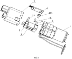
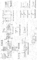
FIG. 1 is an exploded view of pump-valve integrated machine of the present application. -
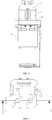
FIG. 2 is a front view of pump-valve integrated machine without housing. -
FIG. 3 is a top view of pump-valve integrated machine without housing. -
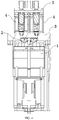
FIG. 4 is a cross-sectional view taken along A-A inFIG. 3 . -
FIG. 5 is a diagram of an overall structure of a pump valve connection base of the present application. -
FIG. 6 is a top view of a pump valve connection base of the present application. -
FIG. 7 is a cross-sectional view taken along B-B of a pump valve connection base of the present application. -
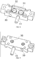
FIG. 8 is a first diagram of an overall structure of an electromagnetic air valve lower base of the present application. -
FIG. 9 is a second diagram of an overall structure of an electromagnetic air valve lower base of the present application. -
FIG. 10 is a diagram of a connection of a normally open electromagnetic air valve with an electromagnetic air valve lower base and an electromagnetic air valve upper cover. -
FIG. 11 is an exploded view ofFIG. 10 . -
FIG. 12 is a partial enlarged view ofFIG. 3 . -
FIG. 13 is a cross-sectional view of the connection between a normally open electromagnetic air valve and an electromagnetic air valve upper cover from another angle. -
FIG. 14 is a schematic diagram of a control circuit board. - In order to make the purpose, technical solutions and advantages of the embodiments of the present application clearer, the technical solutions in the embodiments of the present application will be described clearly and completely in conjunction with the accompanying drawings in the embodiments of the present application. Obviously, the described embodiments are only a part of the embodiments of the present application, but not all of the embodiments.
- Referring to
FIGs. 1 to 4 , the pump-valve integrated machine for a pneumatic lumbar support of an automobile seat provided by the present application includes: anair pump 1, a pumpvalve connection base 2, an electromagnetic air valvelower base 3, a normally openelectromagnetic air valve 4, an electromagnetic air valveupper cover 5, acontrol circuit board 6, and ahousing 7, where theair pump 1 is of the model of JQF1418136, with the manufacturer: Shenzhen Jichuangxing Technology Co., Ltd. Theair pump 1 may be chosen to have one air outlet hole, two air outlet holes, three or more air outlet holes according to actual needs. The air pump with two air outlet holes is selected in this embodiment. A one-way air outlet structure is processed on the pumpvalve connection base 2, and the one-way air outlet structure of the pumpvalve connection base 2 is opposite to and in communication with the air outlet hole of theair pump 1. The electromagnetic air valvelower base 3 is fixed onto theair pump 1 by a bolt. The normally openelectromagnetic air valve 4 is disposed on the electromagnetic air valvelower base 3. The electromagnetic air valveupper cover 5 is disposed above the normally openelectromagnetic air valve 4. The air outlet connector of the electromagnetic air valveupper cover 5 corresponds to the valve core of the normally openelectromagnetic air valve 4. The normally openelectromagnetic air valve 4 is open when power is off. The gas of theair pump 1 is discharged from the air outlet connector of the electromagnetic air valveupper cover 5 through the normally openelectromagnetic air valve 4. When the normally openelectromagnetic air valve 4 is powered on, the gas of theair pump 1 cannot be discharged from the air outlet connector of the electromagnetic air valveupper cover 5 through the normally openelectromagnetic air valve 4. Thecontrol circuit board 6 is used to control the operation of the normally openelectromagnetic air valve 4 and theair pump 1. - Referring to
FIGs. 5 to 7 , the pumpvalve connection base 2 includes arubber sheet bracket 21 and a one-way rubber sheet 22. Aconnection protrusion 24 is processed on the bottom of therubber sheet bracket 21, and theconnection protrusion 24 is disposed on the air outlet hole of theair pump 1. A mounting groove is processed around theconnection protrusion 24, and the mounting groove is provided with asealing ring 8 therein. The mounting hole for the one-way rubber sheet is processed above therubber sheet bracket 21, and anair vent hole 23 is processed around the mounting hole for the one-way rubber sheet. The one-way rubber sheet 22 is disposed in the mounting hole for the one-way rubber sheet and covers theair vent hole 23. A mounting groove is processed around the one-way rubber sheet 22, and thesealing ring 8 is disposed in the mounting groove. - Referring to
FIGs. 8 to 9 , a mountinggroove 31 is processed on bottom of the electromagnetic air valvelower base 3, and the mountinggroove 31 is provided with the pumpvalve connection base 2. Aventilation hole 32 is processed on the electromagnetic air valvelower base 3 at a position opposite to the one-way air outlet structure of the pumpvalve connection base 2, a mounting groove is processed on the electromagnetic air valvelower base 3 and around theventilation hole 32, and a sealing ring is disposed in the mounting groove, and is used to achieve sealing between the electromagnetic air valvelower base 3 and the normally openelectromagnetic air valve 4. - Referring to
FIGs. 10 to 12 , the normally openelectromagnetic air valve 4 includes anouter frame 41, awire rack 42, avalve core 43, arubber plug 44, and aspring 45, where an axialair inlet groove 411 is processed on the bottom of the outer frame, the axial air inlet groove corresponds to theventilation hole 32 of the electromagnetic air valvelower base 3; thewire rack 42 is disposed on theouter frame 41, and a varnished wire is wound outside thewire rack 42; thevalve core 43 is sleeved in thewire rack 42, andgrooves 431 are provided at the upper and lower ends of thevalve core 43, and the rubber plugs 44 are disposed in the two grooves 341; thespring 45 is sleeved at the outer side of the butting section of thevalve core 43 and theouter frame 41, and thevalve core 43 and thewire rack 42 are in clearance fit to form a ventilation passage; the air inlet end of the ventilation passage is communicated with the axialair inlet groove 411, and when thevalve core 43 is under the action of thespring 45, therubber plug 44 is disposed directly above the axialair inlet groove 411. When the normally openelectromagnetic air valve 4 is powered on, therubber plug 44 can form sealing with the axialair inlet groove 411 under the action of an electromagnetic force, preventing theair pump 1 from inflating. - Referring to
FIGs. 12 to 13 , anair outlet passage 51 is disposed in the electromagnetic air valveupper cover 5, and the air outlet hole of theair outlet passage 51 is disposed on the side wall of the electromagnetic air valve upper cover. A noise-reduction cotton is pasted on the outer side of the air outlet hole of the air outlet passage, and is used to reduce the noise. Anair vent hole 52 is processed on theair outlet passage 51 at a position corresponding to therubber plug 44 on the upper end of thevalve core 43, and anair inlet passage 53 is disposed on the side wall of theair vent hole 52, and theair inlet passage 53 is communicated with theair vent hole 52, theair outlet connector 54 and the normally openelectromagnetic air valve 4. In a normal case, a seal forms between therubber plug 44 on the upper end of thevalve core 43 and theair vent hole 52 on theair outlet passage 51, and the air bag is inflated by the gas from the normally openelectromagnetic air valve 4 through theair inlet passage 53 and theair outlet connector 54. When the normally openelectromagnetic air valve 4 is powered on, theair pump 1 stops inflating, and the air in theair bag 1 is discharged through theair outlet connector 54, theair inlet passage 53, theair vent hole 52, and theair outlet passage 51. - The air outlet hole on the
air pump 1 of the present application are respectively connected to the normally openelectromagnetic air valves 4, and each normally openelectromagnetic air valve 4 can individually control the inflation of different air outlet holes, which can achieve inflating of multiple air bags simultaneously, or selectively inflate several air bags of the multiple air bags, which is more full functional and more convenient to use. - Continuing to refer to
FIG. 1 ,FIG. 8, FIG. 9 , in order to detect the inflation of each air bag by theair pump 1 at all times, a mountinghole 33 for a pressure sensor is processed on the side wall of the electromagnetic air valvelower base 3. The mountinghole 33 for the pressure sensor communicates with theventilation hole 32, and the aconnection pipe 9 is disposed outside the mountinghole 33 for the pressure sensor, and theconnection pipe 9 is connected with thepressure sensor 10, and is used to transmit a pressure signal to thepressure sensor 10. Thepressure sensor 10 and a main control chip on thecontrol circuit board 6 are electrically connected. Themain control chip 6 is electrically connected with a drive pump valve chip, and the drive pump valve chip is electrically connected with a control pump interface and a control valve interface, and connected with theair pump 1 and the normally openelectromagnetic air valve 4 by the control pump interface and the control valve interface (FIG. 14 ). When the main control chip detects that the pressure signal exceeds a preset value, the main control chip controls the drive pump valve chip so as to electrify the normally openelectromagnetic air valve 4 and stop inflating the air bag to effectively protect the air bag and prevent the air bag from being inflating to explode. In addition, by setting the pressure value monitored by the main control chip, the height of the air bag can also be adjusted. - Further, in order to make the structure installation of pump-valve integrated machine more compact, the
control circuit board 6 is disposed on the air pump and on one side of the normally open electromagnetic air valve 4 (seeFIG. 1 ,FIG. 13 ), theair pump 1 is electrically connected with the normally openelectromagnetic air valve 4 and thecontrol circuit board 6, and thepressure sensor 10 is disposed on thecontrol circuit board 6 and is disposed between thecontrol circuit board 6 and the electromagnetic air valvelower base 3. - Further, in order to prevent the
control circuit board 6 from being damaged during use, the electromagnetic air valveupper cover 5 and the electromagnetic air valvelower base 3 are each provided with asupport column 11 at a side in contact with thecontrol circuit board 6, to install and support thecontrol circuit board 6. - Further, in order to connect the pump-valve integrated machine with the vehicle body, the pump-valve integrated machine is controlled by the control system in the vehicle body, so as to achieve the adjustment of the height of the pneumatic lumbar support. The
control circuit board 6 is also provided with a button and power supply interface, and a vehicle body communication circuit electrically connected to the main control chip. The button and the power supply interface are connected with a button acquisition circuit and a power supply conversion circuit, and the button acquisition circuit is electrically connected with the main control chip, and the preset pressure valve of the main control chip is adjusted through a button on the vehicle body, achieving the functions such as parameter setting. The power supply conversion circuit is electrically connected with the main control chip through the chip interface (seeFIG. 14 ).
Claims (9)
- A pump-valve integrated machine for a pneumatic lumbar support of an automobile seat, comprising: an air pump, a pump valve connection base, an electromagnetic air valve lower base, a normally open electromagnetic air valve, an electromagnetic air valve upper cover, and a control circuit board, wherein a one-way air outlet structure is processed on the pump valve connection base, and the one-way air outlet structure on the pump valve connection base is opposite to and in communication with an air outlet hole of the air pump; the electromagnetic air valve lower base is fixed onto the air pump, and a mounting groove is processed on a bottom of the electromagnetic air valve lower base, and is provided with the pump valve connection base, a ventilation hole is processed on the electromagnetic air valve lower base opposite to the one-way air outlet structure of the pump valve connection base; the normally open electromagnetic air valve is disposed on the electromagnetic air valve lower base, an air inlet end of the normally open electromagnetic air valve corresponds to the ventilation hole of the electromagnetic air valve lower base; the electromagnetic air valve upper cover is provided above the normally open electromagnetic air valve, and an air outlet connector of the electromagnetic air valve upper cover corresponds to a valve core of the normally open electromagnetic air valve, the normally open electromagnetic air valve is open when it is not powered on, and gas of the air pump is discharged from the air outlet connector through the normally open electromagnetic air valve, and when the normally open electromagnetic air valve is powered on, the gas of the air pump cannot be discharged from the air outlet connector through the normally open electromagnetic air valve; and the control circuit board is configured to control the normally open electromagnetic air valve and the air pump to operate.
- The pump-valve integrated machine for the pneumatic lumbar support of the automobile seat according to claim 1, wherein the pump-valve integrated machine further comprises a housing, the housing is disposed on the air pump, and the electromagnetic air valve lower base, the normally open electromagnetic air valve and the electromagnetic air valve upper cover are provided within the housing.
- The pump-valve integrated machine for the pneumatic lumbar support of the automobile seat according to claim 1, wherein the pump-valve integrated machine further comprises a pressure sensor, and a mounting hole for the pressure sensor is processed on a side wall of the electromagnetic air valve lower base; the mounting hole for the pressure sensor communicates with the ventilation hole, and a connection pipe is disposed outside the mounting hole for the pressure sensor, and the connection pipe is connected with the pressure sensor, and is configured to transmit a pressure signal to the pressure sensor; the pressure sensor and the control circuit board are electrically connected.
- The pump-valve integrated machine for the pneumatic lumbar support of the automobile seat according to any one of claims 1 to 3, wherein the pump valve connection base comprises a rubber sheet bracket and a one-way rubber sheet; a connection protrusion is processed on a bottom of the rubber sheet bracket, and the connection protrusion is disposed on the air outlet hole of the air pump; a mounting groove is processed around the connection protrusion, and is provided with a sealing ring in the mounting groove; a mounting hole for the one-way rubber sheet is processed above the rubber sheet bracket, and an air vent hole is processed around the mounting hole for the one-way rubber sheet; the one-way rubber sheet is disposed in the mounting hole for the one-way rubber sheet and covers the air vent hole; and a mounting groove is processed around the one-way rubber sheet, and provided with a sealing ring in the mounting groove.
- The pump-valve integrated machine for the pneumatic lumbar support of the automobile seat according to any one of claims 1 to 3, wherein a mounting groove is processed on the electromagnetic air valve lower base and around the ventilation hole, and a sealing ring is disposed in the mounting groove, and is configured to achieve sealing between the electromagnetic air valve lower base and the normally open electromagnetic air valve.
- The pump-valve integrated machine for the pneumatic lumbar support of the automobile seat according to any one of claims 1 to 3, wherein the normally open electromagnetic air valve comprises an outer frame, a wire rack, a valve core, a rubber plug, and a spring, wherein an axial air inlet groove is processed on a bottom of the outer frame; the axial air inlet groove corresponds to the ventilation hole of the electromagnetic air valve lower base; the wire rack is disposed on the outer frame, and a varnished wire is wound outside the wire rack; the valve core is sleeved in the wire rack, and upper and lower ends of the valve core are each provided with a groove, and the two grooves are each provided with the rubber plug; the spring is sleeved on an outer side surface of a butting section of the valve core and the outer frame, and the valve core and the wire rack are in clearance fit to form a ventilation passage; an air inlet end of the ventilation passage is communicated with the axial air inlet groove, and when the valve core is under an action of the spring, the rubber plug is disposed directly above the axial air inlet groove, and when the electromagnetic air valve is powered on, the rubber plug is capable of forming sealing with the axial air inlet groove under an action of an electromagnetic force.
- The pump-valve integrated machine for the pneumatic lumbar support of the automobile seat according to any one of claims 1 to 3, wherein an air outlet passage is disposed in the electromagnetic air valve upper cover, and an air outlet hole of the air outlet passage is disposed on a side wall of the electromagnetic air valve upper cover, and an air vent hole is processed on the air outlet passage at a position corresponding to the rubber plug on an upper end of the valve core, an air inlet passage is disposed on a side wall of the air vent hole, and the air inlet passage is communicated with the air vent hole, the air outlet connector and the normally open electromagnetic air valve; in a normal case, a seal forms between the rubber plug on the upper end of the valve core and the air vent hole on the air outlet passage, and an air bag is inflated by the gas from the normally open electromagnetic air valve through the air inlet passage and the air outlet connector; when the electromagnetic air valve is powered on, the air pump stops inflating, and air in the air bag is discharged through the air outlet connector, the air inlet passage, the air vent hole, and the air outlet passage.
- The pump-valve integrated machine for the pneumatic lumbar support of the automobile seat according to claim 7, wherein a placement groove is processed in the electromagnetic air valve upper cover at a position opposite to the wire rack, and one end of the wire rack is inserted into the placement groove; a mounting groove is processed around the placement groove, and is provided with a sealing ring in the mounting groove.
- The pump-valve integrated machine for the pneumatic lumbar support of the automobile seat according to claim 7, wherein a noise-reduction cotton is pasted on the outer side of the air outlet of the air outlet passage.
Applications Claiming Priority (2)
| Application Number | Priority Date | Filing Date | Title |
|---|---|---|---|
| CN201910256177.0A CN110030175B (en) | 2019-04-01 | 2019-04-01 | Pump valve integrated machine for pneumatic waist support of automobile seat |
| PCT/CN2020/082509 WO2020200208A1 (en) | 2019-04-01 | 2020-03-31 | Pump valve all-in-one machine for pneumatic lumbar support of car seat |
Publications (4)
| Publication Number | Publication Date |
|---|---|
| EP3936720A1 true EP3936720A1 (en) | 2022-01-12 |
| EP3936720A4 EP3936720A4 (en) | 2022-03-23 |
| EP3936720C0 EP3936720C0 (en) | 2023-06-07 |
| EP3936720B1 EP3936720B1 (en) | 2023-06-07 |
Family
ID=67237140
Family Applications (1)
| Application Number | Title | Priority Date | Filing Date |
|---|---|---|---|
| EP20784995.1A Active EP3936720B1 (en) | 2019-04-01 | 2020-03-31 | Pump valve all-in-one machine for pneumatic lumbar support of car seat |
Country Status (5)
| Country | Link |
|---|---|
| US (1) | US12078161B2 (en) |
| EP (1) | EP3936720B1 (en) |
| JP (1) | JP7286797B2 (en) |
| CN (1) | CN110030175B (en) |
| WO (1) | WO2020200208A1 (en) |
Families Citing this family (11)
| Publication number | Priority date | Publication date | Assignee | Title |
|---|---|---|---|---|
| CN110030175B (en) * | 2019-04-01 | 2024-04-12 | 新发展(长春)汽车自控系统有限公司 | Pump valve integrated machine for pneumatic waist support of automobile seat |
| CN110822133A (en) * | 2019-11-13 | 2020-02-21 | 东莞市安海思精密电子有限公司 | A composite solenoid valve, pump valve module and car seat |
| WO2021093405A1 (en) | 2019-11-13 | 2021-05-20 | 廊坊市金色时光科技发展有限公司 | Pump valve module and operating method therefor, massage solenoid valve pump valve module for car seat, and car seat |
| CN111791778B (en) * | 2020-06-04 | 2022-03-08 | 廊坊市金色时光科技发展有限公司 | Rocker type regulating switch |
| CN113915106B (en) * | 2020-12-24 | 2025-02-18 | 安闻科技集团股份有限公司 | An integrated pump valve assembly and a pneumatic adjustment system for a car seat |
| CN112959929B (en) * | 2021-02-04 | 2022-06-03 | 廊坊市金色时光科技发展有限公司 | Pneumatic adjusting system for solenoid valve pump valve module and car seat |
| CN113719648A (en) * | 2021-09-13 | 2021-11-30 | 厦门微能电子科技有限公司 | Integrated pump valve with pressure relief function and independently controlled exposed solenoid valve |
| CN113799665B (en) * | 2021-10-29 | 2022-11-22 | 北京经纬恒润科技股份有限公司 | Seat support control method and device |
| CN114837918B (en) * | 2022-04-18 | 2025-02-18 | 江苏恩迪汽车系统股份有限公司 | Quick assembly type pneumatic lumbar support pump valve integrated machine and assembly method |
| CN116080502B (en) * | 2023-02-20 | 2023-07-14 | 长春亚大汽车零件制造有限公司 | Seat valve integrating automobile seat waist support airbag switch and side wing airbag switch |
| US20260022695A1 (en) * | 2024-07-18 | 2026-01-22 | Leggett & Platt Canada Co. | Pump and valve system |
Family Cites Families (24)
| Publication number | Priority date | Publication date | Assignee | Title |
|---|---|---|---|---|
| JP2002364533A (en) * | 2001-06-07 | 2002-12-18 | Saginomiya Seisakusho Inc | Solenoid control valve |
| FR2858432B1 (en) * | 2003-08-01 | 2005-10-07 | Eaton Corp | FLOW AND PRESSURE CONTROL SOLENOID VALVE |
| EP2361800B1 (en) * | 2010-02-17 | 2013-04-24 | L & P Swiss Holding AG | Adjusting device for a seat and method of operating an adjusting device |
| EP2769878B1 (en) * | 2013-02-20 | 2015-03-25 | Schukra Gerätebau GmbH | Seat adjusting device and method of providing seat adjustment |
| WO2015086094A1 (en) * | 2013-12-13 | 2015-06-18 | Kongsberg Automotive Ab | Sma valve for controlling air supply to an air cell in a vehicle seat |
| CN203717289U (en) * | 2014-01-27 | 2014-07-16 | 惠州市唐群电子有限公司 | Control valve capable of being fast installed on air pump |
| CN105443807B (en) * | 2014-07-24 | 2017-11-14 | 惠州市唐群座椅科技股份有限公司 | Combined type distribution valve group |
| CN105443832A (en) * | 2014-07-24 | 2016-03-30 | 惠州市唐群电子有限公司 | Electromagnetic air valve |
| CH711796A1 (en) * | 2015-11-18 | 2017-05-31 | Lantal Textiles Ag | Pneumatic cushion with pump unit. |
| CN107512207A (en) * | 2017-08-23 | 2017-12-26 | 厦门乾泽电子科技有限公司 | A kind of seat adjuster and seat-regulating method |
| CN207670135U (en) * | 2017-12-07 | 2018-07-31 | 青岛孔辉智能悬架系统有限公司 | A kind of highly integrated 5-linked valve of vehicle electrically controlling air suspension |
| CN207814535U (en) * | 2018-02-06 | 2018-09-04 | 厦门乾泽电子科技有限公司 | Electromagnetic gas valve valve group |
| CN208010562U (en) * | 2018-02-06 | 2018-10-26 | 厦门乾泽电子科技有限公司 | Pump-valve integrated micro air pump with normally closed electromagnetic gas valve |
| CN207809133U (en) * | 2018-02-06 | 2018-09-04 | 厦门乾泽电子科技有限公司 | Pneumatic waist support equipped with pump-valve integrated micro air pump |
| CN208010548U (en) * | 2018-02-06 | 2018-10-26 | 厦门乾泽电子科技有限公司 | Pump-valve integrated micro air pump with normally opened electromagnetic gas valve |
| CN108361419B (en) * | 2018-04-10 | 2022-01-11 | 厦门乾泽电子科技有限公司 | Integrated form air valve structure |
| CN208534727U (en) * | 2018-08-03 | 2019-02-22 | 厦门乾泽电子科技有限公司 | Low noise pressure limiting structure and air pump and solenoid valve block with the structure |
| CN110949214A (en) * | 2018-09-27 | 2020-04-03 | 科际精密股份有限公司 | Pump-valve combination for adjusting airbags |
| CN111075698B (en) * | 2018-10-19 | 2021-10-15 | 科际精密股份有限公司 | Pump-valve combination for adjusting airbags |
| CN209164045U (en) * | 2018-11-19 | 2019-07-26 | 浙江锐韦机电科技有限公司 | Integrated pump valve mechanism |
| CN109318770B (en) | 2018-11-27 | 2023-12-12 | 宁波拓普集团股份有限公司 | Seat multi-airbag comfort system integrating lumbar support and multipoint massage |
| CN210068424U (en) * | 2019-04-01 | 2020-02-14 | 新发展(长春)汽车自控系统有限公司 | Pump valve all-in-one machine for pneumatic waist support of automobile seat |
| CN110030175B (en) * | 2019-04-01 | 2024-04-12 | 新发展(长春)汽车自控系统有限公司 | Pump valve integrated machine for pneumatic waist support of automobile seat |
| WO2021093405A1 (en) * | 2019-11-13 | 2021-05-20 | 廊坊市金色时光科技发展有限公司 | Pump valve module and operating method therefor, massage solenoid valve pump valve module for car seat, and car seat |
-
2019
- 2019-04-01 CN CN201910256177.0A patent/CN110030175B/en active Active
-
2020
- 2020-03-31 WO PCT/CN2020/082509 patent/WO2020200208A1/en not_active Ceased
- 2020-03-31 JP JP2021560507A patent/JP7286797B2/en active Active
- 2020-03-31 EP EP20784995.1A patent/EP3936720B1/en active Active
- 2020-03-31 US US17/600,496 patent/US12078161B2/en active Active
Also Published As
| Publication number | Publication date |
|---|---|
| CN110030175B (en) | 2024-04-12 |
| EP3936720C0 (en) | 2023-06-07 |
| US12078161B2 (en) | 2024-09-03 |
| WO2020200208A1 (en) | 2020-10-08 |
| US20220170451A1 (en) | 2022-06-02 |
| EP3936720A4 (en) | 2022-03-23 |
| JP2022528963A (en) | 2022-06-16 |
| EP3936720B1 (en) | 2023-06-07 |
| JP7286797B2 (en) | 2023-06-05 |
| CN110030175A (en) | 2019-07-19 |
Similar Documents
| Publication | Publication Date | Title |
|---|---|---|
| EP3936720B1 (en) | Pump valve all-in-one machine for pneumatic lumbar support of car seat | |
| US5904172A (en) | Valve enclosure assembly | |
| CN105172492B (en) | A kind of bicycle intelligence pressure-sensitive aerating device | |
| EP3674560B1 (en) | An air pump for an inflatable body | |
| WO1996010903A3 (en) | Valve connector | |
| CN211009180U (en) | A high and low pressure integrated air pump and inflatable product | |
| EP3653878A1 (en) | Pump-valve integrated mechanism | |
| CN110822133A (en) | A composite solenoid valve, pump valve module and car seat | |
| CN210068424U (en) | Pump valve all-in-one machine for pneumatic waist support of automobile seat | |
| CN110513312B (en) | Inflation and deflation air pump | |
| CN210290878U (en) | Four-position three-way electromagnetic valve capable of being freely combined | |
| CN216554292U (en) | Air circuit conversion board and automobile seat waist support air pump valve integrated structure | |
| WO2005079296A3 (en) | Airframe tent and pump | |
| CN210769398U (en) | Internal and external air pump assembly and inflatable product | |
| CN213138569U (en) | Pump and valve integrated mechanism for pneumatic waist support | |
| CN210290852U (en) | Three-linkage two-position three-way electromagnetic valve with automatic pressure relief function and one-way valve | |
| CN218661186U (en) | Inflatable external tire pressure monitoring sensing device | |
| CN217270739U (en) | Integrated pump valve for adjusting pneumatic waist support of seat | |
| CN210290879U (en) | Two-position three-way electromagnetic valve with automatic pressure relief function | |
| CN217319957U (en) | Integrated air supply unit of air suspension | |
| CN211116531U (en) | Air charging and discharging device | |
| CN2614959Y (en) | Adjustable pressure tyre inflating connector | |
| CN210397811U (en) | Two-position three-way electromagnetic valve with one-way valve | |
| CN219838391U (en) | Integrated valve assembly, wheel inflation and deflation system and vehicle | |
| CN113982886A (en) | Air pump valve integrated structure for automobile seat waist support and use method |
Legal Events
| Date | Code | Title | Description |
|---|---|---|---|
| STAA | Information on the status of an ep patent application or granted ep patent |
Free format text: STATUS: THE INTERNATIONAL PUBLICATION HAS BEEN MADE |
|
| PUAI | Public reference made under article 153(3) epc to a published international application that has entered the european phase |
Free format text: ORIGINAL CODE: 0009012 |
|
| STAA | Information on the status of an ep patent application or granted ep patent |
Free format text: STATUS: REQUEST FOR EXAMINATION WAS MADE |
|
| 17P | Request for examination filed |
Effective date: 20211007 |
|
| AK | Designated contracting states |
Kind code of ref document: A1 Designated state(s): AL AT BE BG CH CY CZ DE DK EE ES FI FR GB GR HR HU IE IS IT LI LT LU LV MC MK MT NL NO PL PT RO RS SE SI SK SM TR |
|
| A4 | Supplementary search report drawn up and despatched |
Effective date: 20220221 |
|
| RIC1 | Information provided on ipc code assigned before grant |
Ipc: F04B 45/04 20060101ALI20220215BHEP Ipc: F04B 43/02 20060101ALI20220215BHEP Ipc: B60N 2/66 20060101ALI20220215BHEP Ipc: F04B 49/22 20060101ALI20220215BHEP Ipc: F04B 39/00 20060101ALI20220215BHEP Ipc: F04B 39/10 20060101AFI20220215BHEP |
|
| DAV | Request for validation of the european patent (deleted) | ||
| DAX | Request for extension of the european patent (deleted) | ||
| GRAP | Despatch of communication of intention to grant a patent |
Free format text: ORIGINAL CODE: EPIDOSNIGR1 |
|
| STAA | Information on the status of an ep patent application or granted ep patent |
Free format text: STATUS: GRANT OF PATENT IS INTENDED |
|
| INTG | Intention to grant announced |
Effective date: 20221206 |
|
| GRAS | Grant fee paid |
Free format text: ORIGINAL CODE: EPIDOSNIGR3 |
|
| GRAA | (expected) grant |
Free format text: ORIGINAL CODE: 0009210 |
|
| STAA | Information on the status of an ep patent application or granted ep patent |
Free format text: STATUS: THE PATENT HAS BEEN GRANTED |
|
| AK | Designated contracting states |
Kind code of ref document: B1 Designated state(s): AL AT BE BG CH CY CZ DE DK EE ES FI FR GB GR HR HU IE IS IT LI LT LU LV MC MK MT NL NO PL PT RO RS SE SI SK SM TR |
|
| REG | Reference to a national code |
Ref country code: GB Ref legal event code: FG4D |
|
| REG | Reference to a national code |
Ref country code: CH Ref legal event code: EP Ref country code: AT Ref legal event code: REF Ref document number: 1575834 Country of ref document: AT Kind code of ref document: T Effective date: 20230615 Ref country code: DE Ref legal event code: R096 Ref document number: 602020012278 Country of ref document: DE |
|
| U01 | Request for unitary effect filed |
Effective date: 20230703 |
|
| U07 | Unitary effect registered |
Designated state(s): AT BE BG DE DK EE FI FR IT LT LU LV MT NL PT SE SI Effective date: 20230713 |
|
| REG | Reference to a national code |
Ref country code: LT Ref legal event code: MG9D |
|
| PG25 | Lapsed in a contracting state [announced via postgrant information from national office to epo] |
Ref country code: NO Free format text: LAPSE BECAUSE OF FAILURE TO SUBMIT A TRANSLATION OF THE DESCRIPTION OR TO PAY THE FEE WITHIN THE PRESCRIBED TIME-LIMIT Effective date: 20230907 Ref country code: ES Free format text: LAPSE BECAUSE OF FAILURE TO SUBMIT A TRANSLATION OF THE DESCRIPTION OR TO PAY THE FEE WITHIN THE PRESCRIBED TIME-LIMIT Effective date: 20230607 |
|
| PG25 | Lapsed in a contracting state [announced via postgrant information from national office to epo] |
Ref country code: RS Free format text: LAPSE BECAUSE OF FAILURE TO SUBMIT A TRANSLATION OF THE DESCRIPTION OR TO PAY THE FEE WITHIN THE PRESCRIBED TIME-LIMIT Effective date: 20230607 Ref country code: HR Free format text: LAPSE BECAUSE OF FAILURE TO SUBMIT A TRANSLATION OF THE DESCRIPTION OR TO PAY THE FEE WITHIN THE PRESCRIBED TIME-LIMIT Effective date: 20230607 Ref country code: GR Free format text: LAPSE BECAUSE OF FAILURE TO SUBMIT A TRANSLATION OF THE DESCRIPTION OR TO PAY THE FEE WITHIN THE PRESCRIBED TIME-LIMIT Effective date: 20230908 |
|
| PG25 | Lapsed in a contracting state [announced via postgrant information from national office to epo] |
Ref country code: SK Free format text: LAPSE BECAUSE OF FAILURE TO SUBMIT A TRANSLATION OF THE DESCRIPTION OR TO PAY THE FEE WITHIN THE PRESCRIBED TIME-LIMIT Effective date: 20230607 |
|
| PG25 | Lapsed in a contracting state [announced via postgrant information from national office to epo] |
Ref country code: IS Free format text: LAPSE BECAUSE OF FAILURE TO SUBMIT A TRANSLATION OF THE DESCRIPTION OR TO PAY THE FEE WITHIN THE PRESCRIBED TIME-LIMIT Effective date: 20231007 |
|
| PG25 | Lapsed in a contracting state [announced via postgrant information from national office to epo] |
Ref country code: SM Free format text: LAPSE BECAUSE OF FAILURE TO SUBMIT A TRANSLATION OF THE DESCRIPTION OR TO PAY THE FEE WITHIN THE PRESCRIBED TIME-LIMIT Effective date: 20230607 Ref country code: SK Free format text: LAPSE BECAUSE OF FAILURE TO SUBMIT A TRANSLATION OF THE DESCRIPTION OR TO PAY THE FEE WITHIN THE PRESCRIBED TIME-LIMIT Effective date: 20230607 Ref country code: RO Free format text: LAPSE BECAUSE OF FAILURE TO SUBMIT A TRANSLATION OF THE DESCRIPTION OR TO PAY THE FEE WITHIN THE PRESCRIBED TIME-LIMIT Effective date: 20230607 Ref country code: IS Free format text: LAPSE BECAUSE OF FAILURE TO SUBMIT A TRANSLATION OF THE DESCRIPTION OR TO PAY THE FEE WITHIN THE PRESCRIBED TIME-LIMIT Effective date: 20231007 Ref country code: CZ Free format text: LAPSE BECAUSE OF FAILURE TO SUBMIT A TRANSLATION OF THE DESCRIPTION OR TO PAY THE FEE WITHIN THE PRESCRIBED TIME-LIMIT Effective date: 20230607 |
|
| PG25 | Lapsed in a contracting state [announced via postgrant information from national office to epo] |
Ref country code: PL Free format text: LAPSE BECAUSE OF FAILURE TO SUBMIT A TRANSLATION OF THE DESCRIPTION OR TO PAY THE FEE WITHIN THE PRESCRIBED TIME-LIMIT Effective date: 20230607 |
|
| REG | Reference to a national code |
Ref country code: DE Ref legal event code: R097 Ref document number: 602020012278 Country of ref document: DE |
|
| PLBE | No opposition filed within time limit |
Free format text: ORIGINAL CODE: 0009261 |
|
| STAA | Information on the status of an ep patent application or granted ep patent |
Free format text: STATUS: NO OPPOSITION FILED WITHIN TIME LIMIT |
|
| U20 | Renewal fee for the european patent with unitary effect paid |
Year of fee payment: 5 Effective date: 20240327 |
|
| 26N | No opposition filed |
Effective date: 20240308 |
|
| REG | Reference to a national code |
Ref country code: CH Ref legal event code: PL |
|
| PG25 | Lapsed in a contracting state [announced via postgrant information from national office to epo] |
Ref country code: MC Free format text: LAPSE BECAUSE OF FAILURE TO SUBMIT A TRANSLATION OF THE DESCRIPTION OR TO PAY THE FEE WITHIN THE PRESCRIBED TIME-LIMIT Effective date: 20230607 |
|
| GBPC | Gb: european patent ceased through non-payment of renewal fee |
Effective date: 20240331 |
|
| PG25 | Lapsed in a contracting state [announced via postgrant information from national office to epo] |
Ref country code: MC Free format text: LAPSE BECAUSE OF FAILURE TO SUBMIT A TRANSLATION OF THE DESCRIPTION OR TO PAY THE FEE WITHIN THE PRESCRIBED TIME-LIMIT Effective date: 20230607 |
|
| PG25 | Lapsed in a contracting state [announced via postgrant information from national office to epo] |
Ref country code: GB Free format text: LAPSE BECAUSE OF NON-PAYMENT OF DUE FEES Effective date: 20240331 |
|
| PG25 | Lapsed in a contracting state [announced via postgrant information from national office to epo] |
Ref country code: IE Free format text: LAPSE BECAUSE OF NON-PAYMENT OF DUE FEES Effective date: 20240331 |
|
| PG25 | Lapsed in a contracting state [announced via postgrant information from national office to epo] |
Ref country code: IE Free format text: LAPSE BECAUSE OF NON-PAYMENT OF DUE FEES Effective date: 20240331 Ref country code: GB Free format text: LAPSE BECAUSE OF NON-PAYMENT OF DUE FEES Effective date: 20240331 Ref country code: CH Free format text: LAPSE BECAUSE OF NON-PAYMENT OF DUE FEES Effective date: 20240331 |
|
| U20 | Renewal fee for the european patent with unitary effect paid |
Year of fee payment: 6 Effective date: 20250331 |
|
| PG25 | Lapsed in a contracting state [announced via postgrant information from national office to epo] |
Ref country code: CY Free format text: LAPSE BECAUSE OF FAILURE TO SUBMIT A TRANSLATION OF THE DESCRIPTION OR TO PAY THE FEE WITHIN THE PRESCRIBED TIME-LIMIT; INVALID AB INITIO Effective date: 20200331 |
|
| PG25 | Lapsed in a contracting state [announced via postgrant information from national office to epo] |
Ref country code: HU Free format text: LAPSE BECAUSE OF FAILURE TO SUBMIT A TRANSLATION OF THE DESCRIPTION OR TO PAY THE FEE WITHIN THE PRESCRIBED TIME-LIMIT; INVALID AB INITIO Effective date: 20200331 |
|
| PG25 | Lapsed in a contracting state [announced via postgrant information from national office to epo] |
Ref country code: TR Free format text: LAPSE BECAUSE OF FAILURE TO SUBMIT A TRANSLATION OF THE DESCRIPTION OR TO PAY THE FEE WITHIN THE PRESCRIBED TIME-LIMIT Effective date: 20230607 |