EP3936715B1 - Parc éolien à capacité de transmission limitée - Google Patents
Parc éolien à capacité de transmission limitée Download PDFInfo
- Publication number
- EP3936715B1 EP3936715B1 EP21181441.3A EP21181441A EP3936715B1 EP 3936715 B1 EP3936715 B1 EP 3936715B1 EP 21181441 A EP21181441 A EP 21181441A EP 3936715 B1 EP3936715 B1 EP 3936715B1
- Authority
- EP
- European Patent Office
- Prior art keywords
- power
- wind turbine
- electrical
- wind
- turbine generators
- Prior art date
- Legal status (The legal status is an assumption and is not a legal conclusion. Google has not performed a legal analysis and makes no representation as to the accuracy of the status listed.)
- Active
Links
- 230000005540 biological transmission Effects 0.000 title claims description 30
- 239000001257 hydrogen Substances 0.000 claims description 60
- 229910052739 hydrogen Inorganic materials 0.000 claims description 60
- UFHFLCQGNIYNRP-UHFFFAOYSA-N Hydrogen Chemical compound [H][H] UFHFLCQGNIYNRP-UHFFFAOYSA-N 0.000 claims description 56
- 238000012545 processing Methods 0.000 claims description 29
- 238000003860 storage Methods 0.000 claims description 19
- 238000004519 manufacturing process Methods 0.000 claims description 15
- 238000010248 power generation Methods 0.000 claims description 15
- 238000004891 communication Methods 0.000 claims description 7
- 238000000034 method Methods 0.000 claims description 3
- 239000000446 fuel Substances 0.000 description 40
- 239000000498 cooling water Substances 0.000 description 30
- 238000011084 recovery Methods 0.000 description 19
- 238000010438 heat treatment Methods 0.000 description 12
- 239000007788 liquid Substances 0.000 description 12
- 238000005868 electrolysis reaction Methods 0.000 description 10
- 239000007787 solid Substances 0.000 description 9
- 239000000110 cooling liquid Substances 0.000 description 8
- 239000002918 waste heat Substances 0.000 description 8
- XLYOFNOQVPJJNP-UHFFFAOYSA-N water Substances O XLYOFNOQVPJJNP-UHFFFAOYSA-N 0.000 description 8
- 238000001816 cooling Methods 0.000 description 6
- 239000012528 membrane Substances 0.000 description 5
- 230000002441 reversible effect Effects 0.000 description 5
- 239000003011 anion exchange membrane Substances 0.000 description 4
- 238000010612 desalination reaction Methods 0.000 description 4
- 239000007789 gas Substances 0.000 description 4
- 150000002431 hydrogen Chemical class 0.000 description 4
- 230000001172 regenerating effect Effects 0.000 description 4
- 239000013535 sea water Substances 0.000 description 4
- 238000006243 chemical reaction Methods 0.000 description 3
- IJGRMHOSHXDMSA-UHFFFAOYSA-N Atomic nitrogen Chemical compound N#N IJGRMHOSHXDMSA-UHFFFAOYSA-N 0.000 description 2
- LRHPLDYGYMQRHN-UHFFFAOYSA-N N-Butanol Chemical compound CCCCO LRHPLDYGYMQRHN-UHFFFAOYSA-N 0.000 description 2
- 239000000969 carrier Substances 0.000 description 2
- 238000002485 combustion reaction Methods 0.000 description 2
- 239000008367 deionised water Substances 0.000 description 2
- 229910021641 deionized water Inorganic materials 0.000 description 2
- 230000005611 electricity Effects 0.000 description 2
- VNWKTOKETHGBQD-UHFFFAOYSA-N methane Chemical compound C VNWKTOKETHGBQD-UHFFFAOYSA-N 0.000 description 2
- 239000012071 phase Substances 0.000 description 2
- 238000012546 transfer Methods 0.000 description 2
- QGZKDVFQNNGYKY-UHFFFAOYSA-N Ammonia Chemical compound N QGZKDVFQNNGYKY-UHFFFAOYSA-N 0.000 description 1
- MYMOFIZGZYHOMD-UHFFFAOYSA-N Dioxygen Chemical compound O=O MYMOFIZGZYHOMD-UHFFFAOYSA-N 0.000 description 1
- 238000010521 absorption reaction Methods 0.000 description 1
- 230000009286 beneficial effect Effects 0.000 description 1
- 239000001273 butane Substances 0.000 description 1
- 230000006835 compression Effects 0.000 description 1
- 238000007906 compression Methods 0.000 description 1
- 239000004020 conductor Substances 0.000 description 1
- 230000007797 corrosion Effects 0.000 description 1
- 238000005260 corrosion Methods 0.000 description 1
- 230000001419 dependent effect Effects 0.000 description 1
- 230000006866 deterioration Effects 0.000 description 1
- 238000011161 development Methods 0.000 description 1
- 238000009826 distribution Methods 0.000 description 1
- 239000003651 drinking water Substances 0.000 description 1
- 235000020188 drinking water Nutrition 0.000 description 1
- 230000000694 effects Effects 0.000 description 1
- 238000004146 energy storage Methods 0.000 description 1
- 230000014509 gene expression Effects 0.000 description 1
- XLYOFNOQVPJJNP-UHFFFAOYSA-M hydroxide Chemical group [OH-] XLYOFNOQVPJJNP-UHFFFAOYSA-M 0.000 description 1
- 238000009434 installation Methods 0.000 description 1
- 238000003973 irrigation Methods 0.000 description 1
- 230000002262 irrigation Effects 0.000 description 1
- 239000003621 irrigation water Substances 0.000 description 1
- 239000007791 liquid phase Substances 0.000 description 1
- 239000000463 material Substances 0.000 description 1
- IJDNQMDRQITEOD-UHFFFAOYSA-N n-butane Chemical compound CCCC IJDNQMDRQITEOD-UHFFFAOYSA-N 0.000 description 1
- OFBQJSOFQDEBGM-UHFFFAOYSA-N n-pentane Natural products CCCCC OFBQJSOFQDEBGM-UHFFFAOYSA-N 0.000 description 1
- 230000007935 neutral effect Effects 0.000 description 1
- 229910052757 nitrogen Inorganic materials 0.000 description 1
- 238000005457 optimization Methods 0.000 description 1
- 238000005381 potential energy Methods 0.000 description 1
- 238000001179 sorption measurement Methods 0.000 description 1
- 230000003019 stabilising effect Effects 0.000 description 1
- 239000008400 supply water Substances 0.000 description 1
- 230000002123 temporal effect Effects 0.000 description 1
Images


Classifications
-
- F—MECHANICAL ENGINEERING; LIGHTING; HEATING; WEAPONS; BLASTING
- F03—MACHINES OR ENGINES FOR LIQUIDS; WIND, SPRING, OR WEIGHT MOTORS; PRODUCING MECHANICAL POWER OR A REACTIVE PROPULSIVE THRUST, NOT OTHERWISE PROVIDED FOR
- F03D—WIND MOTORS
- F03D9/00—Adaptations of wind motors for special use; Combinations of wind motors with apparatus driven thereby; Wind motors specially adapted for installation in particular locations
- F03D9/20—Wind motors characterised by the driven apparatus
- F03D9/25—Wind motors characterised by the driven apparatus the apparatus being an electrical generator
- F03D9/255—Wind motors characterised by the driven apparatus the apparatus being an electrical generator connected to electrical distribution networks; Arrangements therefor
- F03D9/257—Wind motors characterised by the driven apparatus the apparatus being an electrical generator connected to electrical distribution networks; Arrangements therefor the wind motor being part of a wind farm
-
- F—MECHANICAL ENGINEERING; LIGHTING; HEATING; WEAPONS; BLASTING
- F03—MACHINES OR ENGINES FOR LIQUIDS; WIND, SPRING, OR WEIGHT MOTORS; PRODUCING MECHANICAL POWER OR A REACTIVE PROPULSIVE THRUST, NOT OTHERWISE PROVIDED FOR
- F03D—WIND MOTORS
- F03D9/00—Adaptations of wind motors for special use; Combinations of wind motors with apparatus driven thereby; Wind motors specially adapted for installation in particular locations
- F03D9/10—Combinations of wind motors with apparatus storing energy
- F03D9/19—Combinations of wind motors with apparatus storing energy storing chemical energy, e.g. using electrolysis
-
- F—MECHANICAL ENGINEERING; LIGHTING; HEATING; WEAPONS; BLASTING
- F05—INDEXING SCHEMES RELATING TO ENGINES OR PUMPS IN VARIOUS SUBCLASSES OF CLASSES F01-F04
- F05B—INDEXING SCHEME RELATING TO WIND, SPRING, WEIGHT, INERTIA OR LIKE MOTORS, TO MACHINES OR ENGINES FOR LIQUIDS COVERED BY SUBCLASSES F03B, F03D AND F03G
- F05B2220/00—Application
- F05B2220/61—Application for hydrogen and/or oxygen production
-
- F—MECHANICAL ENGINEERING; LIGHTING; HEATING; WEAPONS; BLASTING
- F05—INDEXING SCHEMES RELATING TO ENGINES OR PUMPS IN VARIOUS SUBCLASSES OF CLASSES F01-F04
- F05B—INDEXING SCHEME RELATING TO WIND, SPRING, WEIGHT, INERTIA OR LIKE MOTORS, TO MACHINES OR ENGINES FOR LIQUIDS COVERED BY SUBCLASSES F03B, F03D AND F03G
- F05B2240/00—Components
- F05B2240/90—Mounting on supporting structures or systems
- F05B2240/96—Mounting on supporting structures or systems as part of a wind turbine farm
-
- Y—GENERAL TAGGING OF NEW TECHNOLOGICAL DEVELOPMENTS; GENERAL TAGGING OF CROSS-SECTIONAL TECHNOLOGIES SPANNING OVER SEVERAL SECTIONS OF THE IPC; TECHNICAL SUBJECTS COVERED BY FORMER USPC CROSS-REFERENCE ART COLLECTIONS [XRACs] AND DIGESTS
- Y02—TECHNOLOGIES OR APPLICATIONS FOR MITIGATION OR ADAPTATION AGAINST CLIMATE CHANGE
- Y02E—REDUCTION OF GREENHOUSE GAS [GHG] EMISSIONS, RELATED TO ENERGY GENERATION, TRANSMISSION OR DISTRIBUTION
- Y02E10/00—Energy generation through renewable energy sources
- Y02E10/70—Wind energy
- Y02E10/72—Wind turbines with rotation axis in wind direction
-
- Y—GENERAL TAGGING OF NEW TECHNOLOGICAL DEVELOPMENTS; GENERAL TAGGING OF CROSS-SECTIONAL TECHNOLOGIES SPANNING OVER SEVERAL SECTIONS OF THE IPC; TECHNICAL SUBJECTS COVERED BY FORMER USPC CROSS-REFERENCE ART COLLECTIONS [XRACs] AND DIGESTS
- Y02—TECHNOLOGIES OR APPLICATIONS FOR MITIGATION OR ADAPTATION AGAINST CLIMATE CHANGE
- Y02E—REDUCTION OF GREENHOUSE GAS [GHG] EMISSIONS, RELATED TO ENERGY GENERATION, TRANSMISSION OR DISTRIBUTION
- Y02E60/00—Enabling technologies; Technologies with a potential or indirect contribution to GHG emissions mitigation
- Y02E60/30—Hydrogen technology
- Y02E60/36—Hydrogen production from non-carbon containing sources, e.g. by water electrolysis
-
- Y—GENERAL TAGGING OF NEW TECHNOLOGICAL DEVELOPMENTS; GENERAL TAGGING OF CROSS-SECTIONAL TECHNOLOGIES SPANNING OVER SEVERAL SECTIONS OF THE IPC; TECHNICAL SUBJECTS COVERED BY FORMER USPC CROSS-REFERENCE ART COLLECTIONS [XRACs] AND DIGESTS
- Y02—TECHNOLOGIES OR APPLICATIONS FOR MITIGATION OR ADAPTATION AGAINST CLIMATE CHANGE
- Y02E—REDUCTION OF GREENHOUSE GAS [GHG] EMISSIONS, RELATED TO ENERGY GENERATION, TRANSMISSION OR DISTRIBUTION
- Y02E70/00—Other energy conversion or management systems reducing GHG emissions
- Y02E70/30—Systems combining energy storage with energy generation of non-fossil origin
Definitions
- the disclosure relates to a wind farm comprising a plurality of wind turbine generator (WTG), each comprising a rotor having one or more blades and an electrical generator driven by said rotor for converting rotation thereof into electrical power.
- WTG wind turbine generator
- Each wind turbine generator further comprises an electrolyser arrangement for production of hydrogen arranged for using electrical power from the electrical generator, a hydrogen storage arrangement for storing hydrogen produced by the electrolyser arrangement, and an electrical power generation arrangement for converting the stored hydrogen to electrical power.
- the wind farm further comprises a power transmission line for transmitting electrical power from the electrical generator and the electrical power generation arrangement of each of the wind turbine generators to an electrical grid.
- the number of new wind farms comprising a plurality of wind turbine generators is continuing to grow and existing wind farms, where expedient, are maintained and updated.
- the operation of the wind farms and the wind turbine generators are continuously improved for increased energy production from each WTG and the wind farms as a whole.
- Forecasts and optimization of the operation of the WTGs relying on large amounts of data and processing hereof are well established elements of operating the WTGs for improved production in consideration of not compromising the lifespan of the WTGs in particular the blades.
- Efforts are also made in increasing the nominal production capacity of the WTGs in order to lower the installation costs per installed MW production capacity and in further standardizing various components used in wind farms across different WTG platforms in order to improve competition conditions for producers of components and thereby minimize production costs of the wind farms.
- a wind farm comprising a plurality of wind turbine generators.
- Each wind turbine generator comprises a rotor having one or more blades and an electrical generator driven by said rotor for converting rotation thereof into electrical power.
- Each wind turbine generator further comprises an electrolyser arrangement for production of hydrogen arranged for using electrical power from the electrical generator, a hydrogen storage arrangement for storing hydrogen produced by the electrolyser arrangement, and an electrical power generation arrangement for converting the stored hydrogen to electrical power.
- the electrolyzer arrangement and the electrical power generation arrangement may be constituted by one or more stacks of regenerative or reversible fuel cells, i.e. by the same arrangement that can be operated for both purposes.
- the wind farm also comprises a power transmission line for transmitting electrical power from the electrical generator and the electrical power generation arrangement of each of the wind turbine generators to an electrical grid.
- the nominal power that can be transmitted from the wind farm by means of the power transmission line constitute no more than 65%, preferably no more than 50%, such as in the range of 15% to 40%, of the sum of the nominal capacity of the electrical generators of all wind turbine generators in the wind farm.
- Nominal capacity may also be known as nameplate capacity.
- the magnitude of the nominal power that can be transmitted from the wind farm by means of the power transmission line is often limited due to the capacity of the transmission grid that receives the power output from the wind farm, but can also be limited due to the capacity of the power transmission line of the wind farm. It is known to dimension the nominal capacity of wind farms, i.e. the sum of the nominal capacities of the electrical generators in the wind farm, to match or slightly overmatch the nominal power capacity that can be transmitted from the wind farm by means of the power transmission line.
- each of the plurality of wind turbine generators with the electrolyzer arrangement for absorbing excess produced power from the electrical generator, the hydrogen storage arrangement for storing the energy and the electric power generation arrangement and dimensioning those correctly, it is possible to provide a wind farm where the nominal capacity of the electrical generators and thus the potential energy production from wind farm by far exceeds the limit of the nominal power capacity that can be transmitted from the wind farm by means of the power transmission line.
- the electrolyzer arrangement uses the excess power to produce hydrogen which may be stored in the hydrogen storage arrangement for later power production by the electric power generation arrangement, such as fuel cells, e.g.
- the wind farm may operate as a baseload power plant, which guarantees a minimum power output to the grid or a combined baseload and peak load power plant.
- the wind farm may comprise further transmission elements, such as an internal power grid connecting each WTG with a substation comprising a transformer for increasing the voltage of power from the internal power grid to e.g. 220 kV and transfer it via the power transmission line to an onshore transmission grid.
- an internal power grid connecting each WTG with a substation comprising a transformer for increasing the voltage of power from the internal power grid to e.g. 220 kV and transfer it via the power transmission line to an onshore transmission grid.
- the wind farm may comprise more wind turbine generators (WTGs) than the mentioned plurality of WTGs.
- WTGs wind turbine generators
- the additional WGTs may differ from the embodiments of WTGs disclosed above and may have a configuration comprising less, more or a different combination of components.
- the nominal power capacity that can be transmitted from the wind farm by means of the power transmission line may be limited e.g. by the capacity of the power transmission line, by capacity of the electrical grid, such as a power transmission grid or a distribution grid, by the capacity of an internal power grid in the wind farm that connects the individual wind turbine generators and/or by the capacity of the connection between the internal power grid and the power transmission line, such as a substation.
- the capacity of the power transmission line e.g. by the capacity of the power transmission line, by capacity of the electrical grid, such as a power transmission grid or a distribution grid, by the capacity of an internal power grid in the wind farm that connects the individual wind turbine generators and/or by the capacity of the connection between the internal power grid and the power transmission line, such as a substation.
- most of or all such components designed for transmitting the electrical power from the wind turbine generators to the electrical grid will have a capacity dimensioned for a common nominal power capacity.
- Hydrogen may be stored physically as either a gas or a liquid. Storage of hydrogen as a gas typically requires high-pressure tanks of 350-700 bar tank pressure, whereas storage of hydrogen as a liquid requires cryogenic temperatures. Hydrogen may also be stored on the surfaces of solids (by adsorption) or within solids (by absorption).
- the local storage of hydrogen may eliminate the need for transporting the hydrogen, which will typically require pressurized tanks or piping systems in case of gaseous hydrogen.
- the transport of hydrogen requires cryogenic temperatures.
- storing the Hydrogen locally and supplying the energy as electricity may use the conventional power grid, which is already part of the wind farm.
- the electrical power generation arrangement may comprise electrochemical fuel cells and/or one or more internal combustion engines.
- the storage of hydrogen may e.g. be performed by means of compression of the hydrogen, by using Liquid Organic Hydrogen Carriers (LOHC) or by other known means.
- LOHC Liquid Organic Hydrogen Carriers
- the hydrogen storage arrangement may comprise a compressor for compressing the generated hydrogen for pressurised storage and/or for feeding to a pressurised hydrogen pipeline.
- the nominal power capacity of the power transmission line may constitute no more than 65%, preferably no more than 50%, such as in the range of 15% to 40%, of the sum of the nominal capacity of the electrical generators of all wind turbine generators in the wind farm.
- each of the plurality of wind turbine generators may further comprise a rectifier for converting alternating current power from the electrical generator to direct current power, a power inverter for converting direct current power from the rectifier and from the electrical power generation arrangement to alternating current power, and a DC-link connecting the rectifier and the power inverter.
- the electrolyzer arrangement may be adapted to be powered by obtaining direct current power from the DC-link and the electrical power generation arrangement may be adapted to provide direct current power to the DC-link.
- the losses in the power inverter are avoided and the electrolyzer arrangement operates normally at a DC power.
- a DC/DC converter may be required between the DC-link and the electrolyzer arrangement.
- Each of the plurality of wind turbine generators may further comprise other flexible loads, such as equipment for production of desalinated water to be used e.g. for irrigation or drinking water, equipment for storage of electric energy in electric batteries or other types of energy storage, equipment for production of liquid ammonia, equipment for production of liquid gas, such as liquid air, liquid oxygen or liquid nitrogen.
- each of the plurality of wind turbine generators may comprise such loads in the form of a data processing centre having one or more data processing units connected to a data communication network and configured to receive, process, store, and transmit data over the data communication network.
- the data processing centre may be adapted to be powered by direct current power from the DC-link whereby the losses in the power inverter are avoided and at least a sizeable part of the data processing centre is operated by DC power albeit at a lower voltage, for which reason a DC/DC converter and means for stabilising the voltage level often will be required between the DC-link and the data processing centre.
- Further wind turbine generators of the wind farm may feed electrical power to the data processing centre of one or more of the plurality of wind turbine generators comprising such data processing centre.
- Local data processing centres for each WTG may be beneficial for distributed computing or processing. By locating the datacentres locally, they may be directly powered be the electrical generator of the WTG either directly or by the stored hydrogen.
- the nominal power capacity of the power inverter of each of the plurality of wind turbine generators may constitute no more than 65%, preferably no more than 50%, such as in the range of 15% to 40%, of the nominal power capacity of the electrical generator of the wind turbine generator.
- the nominal power capacity of the power transmission line may constitute no more than 40%, preferably no more than 30%, such as in the range of 10% to 25%, of the sum of the nominal capacity of the electrical generators of all wind turbine generators in the wind farm.
- the plurality of wind turbine generators may comprise at least 35 wind turbine generators, such as at least 50 wind turbine generators.
- the plurality of wind turbine generators may be arranged in offshore positions.
- the sum of nominal capacity of the electrical generators of the plurality of wind turbine generators may be at least 50 MW, such as at least 250 MW for onshore wind farms and at least 500 MW, such as at least 1,000 MW for offshore farms.
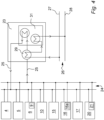
- FIG. 1 A general layout of a wind farm 1 according to the present invention is shown in Fig. 1 .
- the wind farm comprises a plurality of offshore wind turbine generators 2, which are each, equipped with at least one rotor with wind turbine blades 3 arranged to drive an electric generator 4 via a gearbox 5, as illustrated in the embodiment of Fig.2 .
- the generator 4 is connected to a power converter 6 comprising a rectifier 7 for rectifying the alternating-current electric power from the electrical generator 4 and feeding it to a DC-link 8, and an inverter 9 which converts direct-current electric power from the DC-link 8 to a constant-frequency alternating current electric power (typically 50 Hz or 60 Hz, but other frequencies such as 15 Hz or 100 Hz could be employed).
- a constant-frequency alternating current electric power typically 50 Hz or 60 Hz, but other frequencies such as 15 Hz or 100 Hz could be employed.
- the power output from the inverter 9 is transformed to a higher voltage, typically from 0.690 kV to 33 kV by means of a step-up transformer 10 at the wind turbine generator 2.
- the step-up transformer 10 of each wind turbine generator 2 is connected to an internal power grid 11 of the wind farm 1.
- An offshore substation 12 transforms the power from the internal power grid 11 to a higher voltage, such as 220 kV and transfers it via a power transmission line 13 to an onshore transmission grid 14.
- Such wind farm 1 is commonly known and may comprise a number of variations to the above-disclosed details.
- the wind turbine generators 2 may e.g. be designed without a gearbox 5 and instead have direct drive of the generator 4 by the rotor 3, instead of full-scale conversion of the power from the electrical generator 4 by means of the power converter 6, a doubly-fed generator 4 could be employed.
- the power transmission line 13 is a high-voltage direct current (HVDC) connection.
- the individual wind turbine generator 2 could comprise more than one rotor with one or more wind turbine blades 3 and a number of other well-known variations to the wind turbine generators 2 as described above could be implemented without changing the scope and nature of the present invention.
- each of the wind turbine generators 2 further comprises an electrolyzer arrangement 15 for production of hydrogen from electrolysis of water by means of electrical power produced by the generator 4 of the wind turbine generator 2 supplied from the DC-link 8 of the power converter 6.
- the hydrogen from the electrolyzer arrangement 15 is compressed to 350 bar (35 MPa) and stored in the hydrogen storage arrangement 16 of the wind turbine generator 2.
- a fuel cell arrangement 17 is also provided in the wind turbine generator 2, which is arranged for converting hydrogen from the hydrogen storage arrangement 16 into electrical power, which is delivered to the DC-link 8 of the power converter 6.
- the electrolyzer arrangement 15 is alternatively or additionally connected to be powered from the alternating current on one side or the other of the step-up transformer 10, whereby the electrolyzer arrangement 15 more easily can be fed with power from other wind turbine generators WTG 2 of the wind farm 1 by means of the internal power grid 11.
- the electrolyzer arrangement 15 will comprise an AC-DC rectifier unit.
- the electrolyzer arrangement 15 comprises a number of stacks of low-temperature Proton Exchange Membrane (PEM) electrolysis cells which usually has a preferred operating temperature of about 80-100 °C.
- the electrolyzer arrangement 15 comprises alkaline electrolysis cells or anion exchange membrane (AEM) electrolysis cells.
- Other types include high-temperature Proton Exchange Membrane (PEM) electrolysis cells which usually has a preferred operating temperature of about 150-180 °C.
- SOEC Solid Oxide Electrolysis Cell
- the electrolyzer arrangement 15 includes other equipment necessary for operating the electrolysis stacks, such as a power conversion unit to feed the stacks of electrolyser cells with a suitable direct current, a water supply unit for feeding the stacks with deionized water, which may include a desalination apparatus for treating sea water to make it suitable for use in the electrolyser cells, temperature control arrangements for controlling the operating temperature of the stacks of electrolysis cells to be within the optimal operational temperature range, and an electrolyzer control unit for controlling the operation of the electrolyzer arrangement 15.
- a power conversion unit to feed the stacks of electrolyser cells with a suitable direct current
- a water supply unit for feeding the stacks with deionized water
- temperature control arrangements for controlling the operating temperature of the stacks of electrolysis cells to be within the optimal operational temperature range
- an electrolyzer control unit for controlling the operation of the electrolyzer arrangement 15.
- the fuel cell arrangement 17 comprises a number of stacks of low-temperature Proton Exchange Membrane fuel cells (PEMFC) operating preferably at temperatures around 80-100 °C.
- the fuel cell arrangement 17 comprises Alkaline Fuel Cells (AFC) or anion exchange membrane fuel cells (AEMFC), also known as alkaline anion exchange membrane fuel cell (AAEMFC), alkaline membrane fuel cells (AMFC), hydroxide exchange membrane fuel cells (HEMFC), or solid alkaline fuel cells (SAFC).
- AFC Alkaline Fuel Cells
- AEMFC anion exchange membrane fuel cells
- AAEMFC alkaline anion exchange membrane fuel cell
- AMFC alkaline membrane fuel cells
- HEMFC hydroxide exchange membrane fuel cells
- SAFC solid alkaline fuel cells
- SOFC Solid Oxide Fuel Cell
- the fuel cell arrangement 17 includes other equipment necessary for operating the fuel cell stacks, such as a power conversion unit for feeding the power produced by the stacks of fuel cells to the DC-link 8 with a suitable voltage, temperature control arrangements for controlling the operating temperature of the stacks of fuel cells to be within the optimal operational temperature range, and a fuel cell control unit for controlling the operation of the fuel cell arrangement 17.
- a power conversion unit for feeding the power produced by the stacks of fuel cells to the DC-link 8 with a suitable voltage
- temperature control arrangements for controlling the operating temperature of the stacks of fuel cells to be within the optimal operational temperature range
- a fuel cell control unit for controlling the operation of the fuel cell arrangement 17.
- LOHC Liquid Organic Hydrogen Carriers
- Alternative means for storing the produced hydrogen may be incorporated, such as using Liquid Organic Hydrogen Carriers (LOHC) or other well-known storage means.
- LOHC Liquid Organic Hydrogen Carriers
- the use of LOHC may be advantageous because the hydrogen can be stored at ambient temperature and pressure and because the problems of storage of gaseous hydrogen, such as deterioration of materials in contact with the hydrogen by embrittlement and corrosion and risk of leakage are generally solved by the LOHC.
- Other means for electrical power generation from the stored hydrogen could e.g. include an internal combustion engine, such as a piston engine or a gas turbine coupled to an electrical generator.
- the electrolyzer arrangement 15 and the fuel cell arrangement 17 may in certain embodiments be one and the same set of regenerative or reversible fuel cells 15, 17, which may be operated as electrolyzers as well as fuel cells.
- Solid Oxide Electrolysis Cell SOEC
- SOFC Solid Oxide Fuel Cell
- SORFC Solid Oxide Regenerative Fuel Cell
- Such a cell operates at relatively high temperatures (700-1000 °C), which makes the efficiency very high.
- the hydrogen generated in the reversible fuel cells 15, 17 can be stored and reconverted into electricity again by means of the same reversible fuel cells 15, 17, such as Solid Oxide Regenerative Fuel Cell (SORFC).
- Alternative options for reversible fuel cells are e.g. alkaline fuel cells (AFC) and PEM fuel cells.
- the wind farm 1 may be provided with a pressurised hydrogen pipeline 18 that connects the hydrogen storage arrangement 16 of each of the wind turbine generators 2 with an on-shore hydrogen receiving facility 19.
- the hydrogen may be distributed from the on-shore hydrogen receiving facility 19 to various use, be converted into electro fuels, such as butanol, butane or methane, or be stored chemically, such as in LOHC.
- the hydrogen collected from the wind turbine generators 2 may be converted to electro fuel at processing plants arranged offshore at the individual wind turbine generator 2 or at offshore processing plants common for a number of the wind turbine generators 2.
- the hydrogen may alternatively be conveyed from the wind turbine generators 2 to the on-shore hydrogen receiving facility 19 or to an off-shore processing plant by means of a two-string hydrogen piping system (not shown).
- the hydrogen piping system may comprise a LOHC feed pipe arranged for supplying dehydrogenated LOHC to each individual wind turbine generator 2 and a LOHC return pipe arranged for receiving hydrogenated LOHC from the wind turbine generator 2.
- Each of the wind turbine generators 2 is furthermore equipped with a data processing centre 20 having a plurality of data processing units 21 connected to a data communication network 22 of the wind farm 1 and being configured to receive, process, store and transmit data by means of the data processing network 22.
- the data processing centre 20 is arranged to be powered from the DC-link 8 of the power converter 6 where the power is obtained from the electrical generator 4 or from the fuel cell arrangement 17, depending on the state of operation of the wind turbine generator 2.
- the data processing centre 20 is alternatively or additionally connected to be powered from the alternating current on one side or the other of the step-up transformer 10, whereby the data processing centre 20 more easily can be fed with power from other wind turbine generators WTG 2 of the wind farm 1 by means of the internal power grid 11.
- the data processing centre 15 will comprise an AC-DC rectifier unit.
- Fig. 4 illustrates one embodiment of the wind turbine generators 2, which is provided with a heat recovery arrangement 23.
- the illustrated heat recovery arrangement 23 comprises a heat exchange liquid circuit 24 that provides a cooling liquid 25 to the electrical generator 4, the gearbox 5, the power converter 6, where in particular the inverter 9 is in need of cooling off waste heat, the step-up transformer 10, the electrolyzer arrangement 15, the compressor 16a of the hydrogen storage arrangement 16, the fuel cell arrangement 17 and the data processing centre 20, each of which either comprises a heat exchanger for exchanging heat between an internal cooling system of the component and the cooling liquid 25 or uses the cooling liquid 25 directly for cooling of the component 4, 5, 6, 9, 10, 15, 16, 16a, 17, 20.
- the cooling liquid 25 is heated in the components 4, 5, 6, 9, 10, 15, 16, 16a, 17, 20 by absorbing the waste heat from those components 4, 5, 6, 9, 10, 15, 16, 16a, 17, 20 and is returned to the heat recovery arrangement 23.
- the heat recovery arrangement 23 is connected to the AC side of the inverter 9 to obtain operating power from the three AC phases.
- the heat recovery arrangement 23 could be connected to one phase and a neutral conductor or it could be connected to be fed by power from the DC-link 8.
- the wind farm 1 is provided with a heat recovery piping system 26 connecting each of the wind turbine generators 2 with a cooling water feed pipe 27 arranged for supplying cooling water to the heat recovery arrangement 23 of the wind turbine generator 2 and a cooling water return pipe 28 arranged for receiving heated water from the heat recovery arrangement 23.
- the cooling liquid 25 returned from the components 4, 5, 6, 9, 10, 15, 16, 16a, 17, 20 passes through a liquid-liquid heat exchanger 29 in the heat recovery arrangement 23 and delivers the waste heat to the cooling water from the cooling water feed pipe 27, and the heated cooling water is directed to the cooling water return pipe 28.
- the temperature control arrangements of the electrolyzer arrangement 15 and the temperature control arrangements of the fuel cell arrangements 17 employs the heat recovery arrangement 23 to provide heating or cooling to the stacks of electrolysis cells and stacks of fuel cells, respectively, dependent on the operational mode.
- the temperature control arrangements are operated to heat the stacks of cells, preferably to reach their optimal operational temperature range or at least bring them close to that temperature range, and during operation of the stacks of cells, temperature control arrangements are operated to maintain the temperature of the stacks of cells within their optimal temperature range by means of heating or cooling the stacks.
- the cooling water return pipe 28 is connected to an on-shore district heating station 30 where the recovered waste heat from the wind farm 1 is transferred to a district heating system.
- the heat recovery piping system 26 may be connected to more than one on-shore district heating station 30 in order to distribute the heat to more positions.
- the recovered waste heat from the heat recovery piping system 26 may additionally or alternatively be employed to produce electrical power by means of e.g. a Sterling motor or an Organic Rankine Cycle driving an electrical generator or for desalination of seawater, such as by means of a Multiple-Effect Desalination (MED) plant.
- MED Multiple-Effect Desalination
- the cooling water feed pipe 27 may also be applied to supply water of a sufficient purity to the electrolyzer arrangement 15, such as deionized water or water that easily can be purified to a sufficient degree for the electrolyzer arrangement 15 at the wind turbine generator 2.
- the wind turbine generator 2 may be provided with a desalination arrangement (not shown) for providing a supply of water suitable for the electrolyzer arrangement 15.
- the heat recovery arrangement 23 of the wind turbine generator 2 is also provided with a heat pump 31 which is applied for increasing the temperature of cooling water before it is directed to the cooling water return pipe 28 using the cooling liquid 25 as a heat source after it has passed the liquid-liquid heat exchanger 29.
- a heat pump 31 which is applied for increasing the temperature of cooling water before it is directed to the cooling water return pipe 28 using the cooling liquid 25 as a heat source after it has passed the liquid-liquid heat exchanger 29.
- the cooling effect of the cooling liquid 25 is enhanced while the exit temperature of the cooling water delivered to the cooling water return pipe 28 can be elevated to e.g. 80 - 125 °C, which is preferable for some types of district heating systems or for alternative use of the returned cooling water.
- the flow of cooling water from cooling water feed pipe 27 may be increased, both alternatives increases the usable heat flow from the wind turbine generator 2.
- the heat pump 31 is also arranged for heating of cooling water from the cooling water feed pipe 27 using sea water (not shown) as a heat source for use in operational situations where the demand for heat flow from the cooling water returned from the wind turbine generator 2 by the cooling water return pipe 28 cannot be met by the waste heat recovered from the components 4, 5, 6, 9, 10, 15, 16, 16a, 17, 20 of the wind turbine generator 2 by the heat recovery arrangement 23, such as in periods of low wind and/or high demands from the district heating or other consumers of the heat received from the cooling water returned by the cooling water return pipe 28.
- the fuel cell arrangement 17 may be operated to produce sufficient electrical power to operate the heat pump 31 if necessary.
- the wind park 1 may furthermore contain a plurality of further wind turbine generators without one or more of the components disclosed herein.
- the electrolyzer arrangement 15 of each of the plurality of wind turbine generators 2 may furthermore be employed for converting electrical power generated by other wind turbine generators 2 of the wind park 1 with or without its own electrolyzer arrangement 15 into hydrogen.
- each of the wind turbine generators 2 in the form of electrolyzer arrangements 15 and/or data processing centres 20 may furthermore be employed for reducing the power output delivered to the onshore transmission grid 14 during temporal reduction in the power requirements thereof, e.g. during grid failures, by consuming a larger portion of the generated power by the wind turbine generators 2 of the wind farm 1.
- the heat pump may also be adapted for heating of cooling water from the cooling water feed pipe using sea water as a heat source in operational situations, where the demand for heat flow from the cooling water returned from the wind turbine generator 2 by the cooling water return pipe 28 cannot be met by the waste heat recovered from the components 4, 5, 6, 9, 10, 16, 16a, 17 of the wind turbine generator 2 by the heat recovery arrangement 23, such as in periods of low wind and/or high demands from the district heating or other consumers of the heat received from the cooling water returned by the cooling water return pipe 28.
Claims (9)
- Parc éolien (1) comprenant une pluralité de générateurs d'éolienne (2), dont chacun comprendun rotor (3) à une ou plusieurs pales,un générateur électrique (4) entraîné par ledit rotor (3) pour convertir sa rotation en énergie électrique,un agencement d'électrolyseur (15) pour la production d'hydrogène agencé pour utiliser l'énergie électrique du générateur électrique (4),un agencement de stockage d'hydrogène (16) pour stocker l'hydrogène produit par l'agencement d'électrolyseur (15), etun agencement de génération d'énergie électrique (17) pour convertir l'hydrogène stocké en énergie électrique,le parc éolien (1) comprenant en outre une ligne de transmission d'énergie (13) pour transmettre de l'énergie électrique depuis le générateur électrique (4) et l'agencement de génération d'énergie électrique (17) de chacun des générateurs d'éolienne (2) vers un réseau électrique (14), caractérisé en ce que la puissance nominale qui peut être transmise depuis le parc éolien (1) au moyen de la ligne de transmission d'énergie (13) ne constitue pas plus de 65 %, de préférence pas plus de 50 %, telle que dans la plage de 15 % à 40 %, de la somme de la capacité nominale des générateurs électriques (4) de tous les générateurs d'éolienne (2) dans le parc éolien (1).
- Parc éolien (1) selon la revendication 1, dans lequel la capacité de puissance nominale de la ligne de transport d'énergie (13) ne constitue pas plus de 65 %, de préférence pas plus de 50 %, telle que dans la plage de 15 % à 40 %, de la somme de la capacité nominale des générateurs électriques (4) de tous les générateurs d'éolienne (2) dans le parc éolien (1).
- Parc éolien (1) selon la revendication 1 ou 2, dans lequel chacun de la pluralité de générateurs d'éolienne (2) comprend en outreun redresseur (7) pour convertir le courant alternatif du générateur électrique (4) en courant continu,un onduleur de puissance (9) pour convertir le courant continu du redresseur (7) et de l'agencement de génération d'énergie électrique (17) en courant alternatif, etune liaison CC (8) connectant le redresseur (7) et l'onduleur de puissance (9), dans lequel l'agencement d'électrolyseur (15) est conçu pour être alimenté par une alimentation en courant continu provenant de la liaison CC (8) et l'agencement de génération d'énergie électrique (17) est conçu pour fournir une alimentation en courant continu à la liaison CC (8).
- Parc éolien (1) selon la revendication 3, dans lequel chacun de la pluralité de générateurs d'éolienne (2) comprend un centre de traitement de données (20) ayant une ou plusieurs unités de traitement de données (21) connectées à un réseau de communication de données (22) et configurées pour recevoir, traiter, stocker et transmettre des données sur le réseau de communication de données (22), dans lequel le centre de traitement de données (20) est agencé pour être alimenté en obtenant une alimentation en courant continu de la liaison CC (8).
- Parc éolien (1) selon la revendication 3 ou 4, dans lequel la capacité de puissance nominale de l'onduleur de puissance (9) de chacun de la pluralité de générateurs d'éolienne (2) ne constitue pas plus de 65 %, de préférence pas plus de 50 %, telle que dans la plage de 15 % à 40 %, de la capacité de puissance nominale du générateur électrique (4) du générateur d'éolienne (2).
- Parc éolien (1) selon l'une quelconque des revendications 3 à 5, dans lequel la capacité de puissance nominale de la ligne de transmission d'énergie (13) ne représente pas plus de 40 %, de préférence pas plus de 30 %, telle que dans la plage de 10 % à 25 %, de la somme de la capacité nominale des générateurs électriques (4) de tous les générateurs d'éolienne (2) dans le parc éolien (1).
- Parc éolien (1) selon l'une quelconque des revendications précédentes, dans lequel ladite pluralité de générateurs d'éolienne (2) comprend au moins 35 générateurs d'éolienne (2), telle qu'au moins 50 générateurs d'éolienne (2).
- Parc éolien (1) selon l'une quelconque des revendications précédentes, dans lequel ladite pluralité de générateurs d'éolienne (2) sont agencées dans des positions offshore.
- Parc éolien (1) selon l'une quelconque des revendications précédentes, dans lequel la somme de la capacité nominale des générateurs électriques (4) de ladite pluralité de générateurs d'éolienne (2) est d'au moins 50 MW, telle qu'au moins 250 MW pour les parcs éoliens terrestres et au moins 500 MW, telle qu'au moins 1 000 MW pour les parcs offshore.
Applications Claiming Priority (1)
| Application Number | Priority Date | Filing Date | Title |
|---|---|---|---|
| DKPA202070479 | 2020-07-10 |
Publications (3)
| Publication Number | Publication Date |
|---|---|
| EP3936715A1 EP3936715A1 (fr) | 2022-01-12 |
| EP3936715C0 EP3936715C0 (fr) | 2023-07-26 |
| EP3936715B1 true EP3936715B1 (fr) | 2023-07-26 |
Family
ID=76601080
Family Applications (1)
| Application Number | Title | Priority Date | Filing Date |
|---|---|---|---|
| EP21181441.3A Active EP3936715B1 (fr) | 2020-07-10 | 2021-06-24 | Parc éolien à capacité de transmission limitée |
Country Status (1)
| Country | Link |
|---|---|
| EP (1) | EP3936715B1 (fr) |
Families Citing this family (1)
| Publication number | Priority date | Publication date | Assignee | Title |
|---|---|---|---|---|
| EP4283119A1 (fr) * | 2022-05-25 | 2023-11-29 | Siemens Gamesa Renewable Energy A/S | Collecteur d'hydrogène pour éoliennes |
Family Cites Families (2)
| Publication number | Priority date | Publication date | Assignee | Title |
|---|---|---|---|---|
| US7471010B1 (en) * | 2004-09-29 | 2008-12-30 | Alliance For Sustainable Energy, Llc | Wind turbine tower for storing hydrogen and energy |
| ES2299407B1 (es) * | 2007-10-18 | 2009-08-25 | Acciona Energia, S.A. | Sistema de produccion de energia electrica e hidrogeno. |
-
2021
- 2021-06-24 EP EP21181441.3A patent/EP3936715B1/fr active Active
Also Published As
| Publication number | Publication date |
|---|---|
| EP3936715C0 (fr) | 2023-07-26 |
| EP3936715A1 (fr) | 2022-01-12 |
Similar Documents
| Publication | Publication Date | Title |
|---|---|---|
| US11767603B2 (en) | Modular systems for hydrogen generation and methods of operating thereof | |
| AU2012350362B2 (en) | A renewal energy power generation system | |
| CN214798893U (zh) | 制氢系统 | |
| EP3936717A1 (fr) | Parc éolien comportant une tuyauterie de récupération de chaleur | |
| CN110654520A (zh) | 一种采用燃料电池船舶直流组网系统和应用此系统的船舶 | |
| WO2011060953A2 (fr) | Système de gestion d'énergie de bout en bout | |
| CN112448413A (zh) | 一种近零碳排放的分布式能源供给系统及方法 | |
| EP3936715B1 (fr) | Parc éolien à capacité de transmission limitée | |
| CN216280615U (zh) | 一种用于海上制氢及储氢的系统 | |
| CN106402647B (zh) | 一种利用可再生能源的加氢站 | |
| EP3936716B1 (fr) | Parc éolien comprenant des générateurs d'éolienne ayant une capacité d'onduleur réduite | |
| EP3957852A1 (fr) | Parc éolien comportant des centres de traitement de données | |
| US11742670B2 (en) | Energy transmission system and wind farm | |
| DK2642120T3 (en) | Power backup system for a wind turbine | |
| US20230243271A1 (en) | System having a liquid air energy storage and power plant apparatus | |
| CN213341659U (zh) | 一种近零碳排放的分布式能源供给系统 | |
| CN114909871A (zh) | 一种海上离网型超导风电制备液氢的方法及装置 | |
| EP4350142A1 (fr) | Système d'alimentation auxiliaire et commande pour éoliennes rurales et/ou hors réseau | |
| EP4346046A1 (fr) | Turbine éolienne et méthode pour la turbine éolienne | |
| EP4086373A1 (fr) | Système d'électrolyse hydroélectrique | |
| EP4164079A1 (fr) | Système de transmission électrique pour consommateurs flexibles | |
| Barbir | Hydrogen Islands–Utilization of Renewable Energy for an Autonomous Power Supply | |
| CN115719969A (zh) | 海上风电直流系统 | |
| CN115875204A (zh) | 海上风电交流系统 | |
| WO2024041711A1 (fr) | Architecture de réseau power-to-x améliorée |
Legal Events
| Date | Code | Title | Description |
|---|---|---|---|
| PUAI | Public reference made under article 153(3) epc to a published international application that has entered the european phase |
Free format text: ORIGINAL CODE: 0009012 |
|
| STAA | Information on the status of an ep patent application or granted ep patent |
Free format text: STATUS: THE APPLICATION HAS BEEN PUBLISHED |
|
| AK | Designated contracting states |
Kind code of ref document: A1 Designated state(s): AL AT BE BG CH CY CZ DE DK EE ES FI FR GB GR HR HU IE IS IT LI LT LU LV MC MK MT NL NO PL PT RO RS SE SI SK SM TR |
|
| B565 | Issuance of search results under rule 164(2) epc |
Effective date: 20211124 |
|
| STAA | Information on the status of an ep patent application or granted ep patent |
Free format text: STATUS: REQUEST FOR EXAMINATION WAS MADE |
|
| 17P | Request for examination filed |
Effective date: 20220705 |
|
| RBV | Designated contracting states (corrected) |
Designated state(s): AL AT BE BG CH CY CZ DE DK EE ES FI FR GB GR HR HU IE IS IT LI LT LU LV MC MK MT NL NO PL PT RO RS SE SI SK SM TR |
|
| GRAP | Despatch of communication of intention to grant a patent |
Free format text: ORIGINAL CODE: EPIDOSNIGR1 |
|
| STAA | Information on the status of an ep patent application or granted ep patent |
Free format text: STATUS: GRANT OF PATENT IS INTENDED |
|
| INTG | Intention to grant announced |
Effective date: 20230224 |
|
| GRAS | Grant fee paid |
Free format text: ORIGINAL CODE: EPIDOSNIGR3 |
|
| GRAA | (expected) grant |
Free format text: ORIGINAL CODE: 0009210 |
|
| STAA | Information on the status of an ep patent application or granted ep patent |
Free format text: STATUS: THE PATENT HAS BEEN GRANTED |
|
| AK | Designated contracting states |
Kind code of ref document: B1 Designated state(s): AL AT BE BG CH CY CZ DE DK EE ES FI FR GB GR HR HU IE IS IT LI LT LU LV MC MK MT NL NO PL PT RO RS SE SI SK SM TR |
|
| REG | Reference to a national code |
Ref country code: CH Ref legal event code: EP |
|
| REG | Reference to a national code |
Ref country code: DE Ref legal event code: R096 Ref document number: 602021003745 Country of ref document: DE |
|
| REG | Reference to a national code |
Ref country code: IE Ref legal event code: FG4D |
|
| U01 | Request for unitary effect filed |
Effective date: 20230825 |
|
| U07 | Unitary effect registered |
Designated state(s): AT BE BG DE DK EE FI FR IT LT LU LV MT NL PT SE SI Effective date: 20230922 |
|
| REG | Reference to a national code |
Ref country code: LT Ref legal event code: MG9D |
|
| REG | Reference to a national code |
Ref country code: NO Ref legal event code: T2 Effective date: 20230726 |
|
| PG25 | Lapsed in a contracting state [announced via postgrant information from national office to epo] |
Ref country code: GR Free format text: LAPSE BECAUSE OF FAILURE TO SUBMIT A TRANSLATION OF THE DESCRIPTION OR TO PAY THE FEE WITHIN THE PRESCRIBED TIME-LIMIT Effective date: 20231027 |
|
| PG25 | Lapsed in a contracting state [announced via postgrant information from national office to epo] |
Ref country code: IS Free format text: LAPSE BECAUSE OF FAILURE TO SUBMIT A TRANSLATION OF THE DESCRIPTION OR TO PAY THE FEE WITHIN THE PRESCRIBED TIME-LIMIT Effective date: 20231126 |
|
| PG25 | Lapsed in a contracting state [announced via postgrant information from national office to epo] |
Ref country code: RS Free format text: LAPSE BECAUSE OF FAILURE TO SUBMIT A TRANSLATION OF THE DESCRIPTION OR TO PAY THE FEE WITHIN THE PRESCRIBED TIME-LIMIT Effective date: 20230726 Ref country code: IS Free format text: LAPSE BECAUSE OF FAILURE TO SUBMIT A TRANSLATION OF THE DESCRIPTION OR TO PAY THE FEE WITHIN THE PRESCRIBED TIME-LIMIT Effective date: 20231126 Ref country code: HR Free format text: LAPSE BECAUSE OF FAILURE TO SUBMIT A TRANSLATION OF THE DESCRIPTION OR TO PAY THE FEE WITHIN THE PRESCRIBED TIME-LIMIT Effective date: 20230726 Ref country code: GR Free format text: LAPSE BECAUSE OF FAILURE TO SUBMIT A TRANSLATION OF THE DESCRIPTION OR TO PAY THE FEE WITHIN THE PRESCRIBED TIME-LIMIT Effective date: 20231027 |
|
| PG25 | Lapsed in a contracting state [announced via postgrant information from national office to epo] |
Ref country code: PL Free format text: LAPSE BECAUSE OF FAILURE TO SUBMIT A TRANSLATION OF THE DESCRIPTION OR TO PAY THE FEE WITHIN THE PRESCRIBED TIME-LIMIT Effective date: 20230726 |
|
| PG25 | Lapsed in a contracting state [announced via postgrant information from national office to epo] |
Ref country code: ES Free format text: LAPSE BECAUSE OF FAILURE TO SUBMIT A TRANSLATION OF THE DESCRIPTION OR TO PAY THE FEE WITHIN THE PRESCRIBED TIME-LIMIT Effective date: 20230726 |
|
| PLBI | Opposition filed |
Free format text: ORIGINAL CODE: 0009260 |
|
| PG25 | Lapsed in a contracting state [announced via postgrant information from national office to epo] |
Ref country code: SM Free format text: LAPSE BECAUSE OF FAILURE TO SUBMIT A TRANSLATION OF THE DESCRIPTION OR TO PAY THE FEE WITHIN THE PRESCRIBED TIME-LIMIT Effective date: 20230726 Ref country code: RO Free format text: LAPSE BECAUSE OF FAILURE TO SUBMIT A TRANSLATION OF THE DESCRIPTION OR TO PAY THE FEE WITHIN THE PRESCRIBED TIME-LIMIT Effective date: 20230726 Ref country code: ES Free format text: LAPSE BECAUSE OF FAILURE TO SUBMIT A TRANSLATION OF THE DESCRIPTION OR TO PAY THE FEE WITHIN THE PRESCRIBED TIME-LIMIT Effective date: 20230726 Ref country code: CZ Free format text: LAPSE BECAUSE OF FAILURE TO SUBMIT A TRANSLATION OF THE DESCRIPTION OR TO PAY THE FEE WITHIN THE PRESCRIBED TIME-LIMIT Effective date: 20230726 Ref country code: SK Free format text: LAPSE BECAUSE OF FAILURE TO SUBMIT A TRANSLATION OF THE DESCRIPTION OR TO PAY THE FEE WITHIN THE PRESCRIBED TIME-LIMIT Effective date: 20230726 |
|
| PLAB | Opposition data, opponent's data or that of the opponent's representative modified |
Free format text: ORIGINAL CODE: 0009299OPPO |