EP3936668B1 - Aufschüttungselement sowie verfahren zu dessen herstellung - Google Patents
Aufschüttungselement sowie verfahren zu dessen herstellung Download PDFInfo
- Publication number
- EP3936668B1 EP3936668B1 EP21184130.9A EP21184130A EP3936668B1 EP 3936668 B1 EP3936668 B1 EP 3936668B1 EP 21184130 A EP21184130 A EP 21184130A EP 3936668 B1 EP3936668 B1 EP 3936668B1
- Authority
- EP
- European Patent Office
- Prior art keywords
- flood barrier
- barrier element
- solar panel
- flood
- underside
- Prior art date
- Legal status (The legal status is an assumption and is not a legal conclusion. Google has not performed a legal analysis and makes no representation as to the accuracy of the status listed.)
- Active
Links
Images
Classifications
-
- B—PERFORMING OPERATIONS; TRANSPORTING
- B28—WORKING CEMENT, CLAY, OR STONE
- B28B—SHAPING CLAY OR OTHER CERAMIC COMPOSITIONS; SHAPING SLAG; SHAPING MIXTURES CONTAINING CEMENTITIOUS MATERIAL, e.g. PLASTER
- B28B19/00—Machines or methods for applying the material to surfaces to form a permanent layer thereon
- B28B19/0053—Machines or methods for applying the material to surfaces to form a permanent layer thereon to tiles, bricks or the like
-
- E—FIXED CONSTRUCTIONS
- E02—HYDRAULIC ENGINEERING; FOUNDATIONS; SOIL SHIFTING
- E02B—HYDRAULIC ENGINEERING
- E02B3/00—Engineering works in connection with control or use of streams, rivers, coasts, or other marine sites; Sealings or joints for engineering works in general
- E02B3/04—Structures or apparatus for, or methods of, protecting banks, coasts, or harbours
- E02B3/10—Dams; Dykes; Sluice ways or other structures for dykes, dams, or the like
-
- H—ELECTRICITY
- H02—GENERATION; CONVERSION OR DISTRIBUTION OF ELECTRIC POWER
- H02S—GENERATION OF ELECTRIC POWER BY CONVERSION OF INFRARED RADIATION, VISIBLE LIGHT OR ULTRAVIOLET LIGHT, e.g. USING PHOTOVOLTAIC [PV] MODULES
- H02S20/00—Supporting structures for PV modules
- H02S20/20—Supporting structures directly fixed to an immovable object
- H02S20/22—Supporting structures directly fixed to an immovable object specially adapted for buildings
- H02S20/26—Building materials integrated with PV modules, e.g. façade elements
-
- H—ELECTRICITY
- H10—SEMICONDUCTOR DEVICES; ELECTRIC SOLID-STATE DEVICES NOT OTHERWISE PROVIDED FOR
- H10F—INORGANIC SEMICONDUCTOR DEVICES SENSITIVE TO INFRARED RADIATION, LIGHT, ELECTROMAGNETIC RADIATION OF SHORTER WAVELENGTH OR CORPUSCULAR RADIATION
- H10F19/00—Integrated devices, or assemblies of multiple devices, comprising at least one photovoltaic cell covered by group H10F10/00, e.g. photovoltaic modules
- H10F19/80—Encapsulations or containers for integrated devices, or assemblies of multiple devices, having photovoltaic cells
-
- H—ELECTRICITY
- H10—SEMICONDUCTOR DEVICES; ELECTRIC SOLID-STATE DEVICES NOT OTHERWISE PROVIDED FOR
- H10F—INORGANIC SEMICONDUCTOR DEVICES SENSITIVE TO INFRARED RADIATION, LIGHT, ELECTROMAGNETIC RADIATION OF SHORTER WAVELENGTH OR CORPUSCULAR RADIATION
- H10F19/00—Integrated devices, or assemblies of multiple devices, comprising at least one photovoltaic cell covered by group H10F10/00, e.g. photovoltaic modules
- H10F19/80—Encapsulations or containers for integrated devices, or assemblies of multiple devices, having photovoltaic cells
- H10F19/85—Protective back sheets
-
- Y—GENERAL TAGGING OF NEW TECHNOLOGICAL DEVELOPMENTS; GENERAL TAGGING OF CROSS-SECTIONAL TECHNOLOGIES SPANNING OVER SEVERAL SECTIONS OF THE IPC; TECHNICAL SUBJECTS COVERED BY FORMER USPC CROSS-REFERENCE ART COLLECTIONS [XRACs] AND DIGESTS
- Y02—TECHNOLOGIES OR APPLICATIONS FOR MITIGATION OR ADAPTATION AGAINST CLIMATE CHANGE
- Y02B—CLIMATE CHANGE MITIGATION TECHNOLOGIES RELATED TO BUILDINGS, e.g. HOUSING, HOUSE APPLIANCES OR RELATED END-USER APPLICATIONS
- Y02B10/00—Integration of renewable energy sources in buildings
- Y02B10/10—Photovoltaic [PV]
-
- Y—GENERAL TAGGING OF NEW TECHNOLOGICAL DEVELOPMENTS; GENERAL TAGGING OF CROSS-SECTIONAL TECHNOLOGIES SPANNING OVER SEVERAL SECTIONS OF THE IPC; TECHNICAL SUBJECTS COVERED BY FORMER USPC CROSS-REFERENCE ART COLLECTIONS [XRACs] AND DIGESTS
- Y02—TECHNOLOGIES OR APPLICATIONS FOR MITIGATION OR ADAPTATION AGAINST CLIMATE CHANGE
- Y02E—REDUCTION OF GREENHOUSE GAS [GHG] EMISSIONS, RELATED TO ENERGY GENERATION, TRANSMISSION OR DISTRIBUTION
- Y02E10/00—Energy generation through renewable energy sources
- Y02E10/50—Photovoltaic [PV] energy
Definitions
- the invention relates to a method for manufacturing a flood barrier element having a body provided with a rear side with which the flood barrier element abuts against the flood defense during use 1and a water-facing front side
- the flood barrier element comprises a solar panel provided with a sun-facing top side and a underside with which the solar panel is attached on the front side of the body in which method a solar panel is placed with the top on the bottom of a mold and an adhesive layer is applied to the underside of the solar panel, then concrete is poured into the mold on the underside of the solar panel, after which the concrete hardens to a concrete body.
- a method according to the preamble of claim 1 is known from US2018/257260A1 .
- An object of the invention is to improve the known method.
- the method according to the invention is characterized in that after applying the adhesive layer to the underside of the solar panel and before the concrete is poured on the underside of the solar panel, granular material is sprinkled on the adhesive layer that has not yet hardened, after which the concrete is poured on the underside of the solar panel, the flood barrier element comprises a solar panel provided with a top side facing the sun and an underside with which the solar panel is attached to the front side of the body.
- the invention also relates to a flood barrier element for reinforcing/protecting a flood defense comprising a body made of concrete and provided with a rear side with which the flood barrier element abuts against the flood defense during use and a water-facing front side, the flood barrier element comprises a solar panel provided with a sun-facing top side and a underside with which the solar panel is attached on the front side of the body.
- This flood barrier element is characterized in that a granular material is attached to the underside of the solar panel and that the body is attached to the granular material and that the flood barrier element is made according to the above described method.
- the granular material is preferably made of stone, for example gravel, because concrete adheres to it well.
- the granular material is preferably glued to the underside of the solar panel.
- solar panel is understood to mean both a panel and a foil provided with photovoltaic cells.
- An embodiment of the flood barrier element according to the invention is characterized in that through holes are present in the flood barrier element, which holes extend over the entire thickness of the flood barrier element in order to prevent the formation of underpressure under the flood barrier element.
- a further embodiment of the flood barrier element according to the invention is characterized in that grooves are present in the rear side of the body for drainage of water present under the flood barrier element.
- Yet another embodiment of the flood barrier element according to the invention is characterized in that the front side of the body is at an angle with respect to the rear side of the body and that this front side projects beyond the rear side on one side, wherein the beyond the rear side projecting part of the front forms a protruding ridge and the height of the sidewall below this ridge is the same as the height of the opposite sidewall. It is hereby possible that flood barrier elements present one after the other overlap each other with the ridges, so that water cannot get between the flood barrier elements and the underlying soil cannot wash away.
- the invention further relates to a flood defense provided with a number of flood barrier elements, wherein, viewed in the tidal direction, rows of adjacent flood barrier elements are present one behind the other, wherein the flood barrier elements of a row present behind another row with their ridges facing the water are present on edges facing away from the water of the other row of flood barrier elements present in front of it.
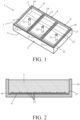
- FIG. 1 shows a perspective view of an embodiment of the flood barrier element according to the invention.
- the flood barrier element 1 is composed of a concrete plate 3 and a number of solar panels 9 mounted thereon.
- the concrete plate 3 is provided with a rear side 5 and a front side 7.
- a flood defense for instance a dike
- the concrete plate lies with the rear side 5 against the dike and the front side 7 is facing the water.
- Each solar panel 9 is provided with a top side 11 for receiving sunlight and an underside 13.
- the top side is made of a hard and wear-resistant material, for instance reinforced fiberglass.
- the solar panel 9 with its underside 13 is attached to the front side 7 of the concrete plate 3.
- Gravel 15 is glued to the underside 13 of the solar panel 9 and the concrete plate 3 is attached to the gravel 15 and the underside 13 of the solar panel 9.
- the solar panel 9 is constructed from a plastic carrier plate 19 and a plastic shielding plate 17 with photovoltaic cells in between.
- through-holes 21 are present in the flood barrier element 1, which holes extend over the entire thickness of the flood barrier element. Furthermore, grooves 23 are present in the rear side 5 of the concrete plate for drainage of water present under the flood barrier element.
- an adhesive layer 14 is applied to the underside 13 of a solar panel 9, after which granular material, for example gravel 15, is sprinkled on the adhesive layer 14 that has not yet hardened.
- the solar panel 9 is then placed with the top side 11 on the bottom 27 of a mold 25 .
- a layer of concrete is poured into the mold on the underside 13 of the solar panel 9. After the concrete has cured, the concrete plate 3 in which the gravel is embedded forms.
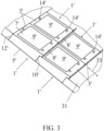
- Figure 3 shows a flood defense in which, viewed in the tidal direction 33, rows of adjacent flood barrier elements 1' are present one behind the other on a dike 31.
- the flood barrier elements 1' of a row present behind another row have a ridge 8' facing the water that is present on an edge facing away from the water of flood barrier elements 1' of the other row in front of this row.
- the front side 7' of the concrete body 3' is present at an angle with respect to the rear side 5' of the concrete body 3'.
- the front side 7' of the concrete body 3' protrudes on one end beyond the rear side 5', the part of the front side projecting beyond the rear side forming a projecting ridge 8'.
- the height of the side wall 10' below this ridge 8' is the same as the height of the opposite side wall 12', so that a further flood barrier element 1' with the side wall 12' can be placed under the ridge 8'.
- the concrete elements are provided with electrical connections (not shown) to be able to electrically connect the solar panels 9' to each other. Furthermore, the concrete plates 3' are, in the front side, provide with bushings 14' with internal screw thread into which bolts provided with eyes can be turned for the purpose of lifting the flood barrier elements.
Landscapes
- Engineering & Computer Science (AREA)
- Civil Engineering (AREA)
- Structural Engineering (AREA)
- General Engineering & Computer Science (AREA)
- Architecture (AREA)
- Mechanical Engineering (AREA)
- Environmental & Geological Engineering (AREA)
- Ocean & Marine Engineering (AREA)
- Chemical & Material Sciences (AREA)
- Ceramic Engineering (AREA)
- Revetment (AREA)
- Photovoltaic Devices (AREA)
Claims (7)
- Verfahren zur Herstellung eines Hochwasserschutzelements (1; 1') mit einem Körper (3; 3'), der mit einer Rückseite (5; 5'), mit der das Hochwasserschutzelement während des Gebrauchs an der Hochwasserabwehr anliegt, und einer dem Wasser zugewandten Vorderseite (7; 7') versehen ist, wobei das Hochwasserschutzelement ein Solarpanel (9) umfasst, das mit einer der Sonne zugewandten Oberseite (11) und einer Unterseite (13) versehen ist, mit der das Solarpanel an der Vorderseite (7; 7') des Körpers (3; 3') befestigt ist, bei welchem Verfahren ein Solarpanel (9) mit der Oberseite (11) auf den Boden (27) einer Form (25) gelegt und eine Klebeschicht (14) auf die Unterseite (13) des Solarpanels (9) aufgetragen wird, dann Beton in die Form auf die Unterseite (13) des Solarpanels (9) gegossen wird, wonach der Beton zu einem Betonkörper (3) aushärtet, dadurch gekennzeichnet, dass nach dem Auftragen der Klebeschicht (14) auf die Unterseite (13) des Solarpanels (9) und vor dem Aufgießen des Betons auf die Unterseite (13) des Solarpanels (9) körniges Material (15) auf die noch nicht ausgehärtete Klebeschicht (14) gestreut wird, wonach der Beton auf die Unterseite (13) des Solarpanels (9) gegossen wird.
- Hochwasserschutzelement (1; 1') zur Verstärkung/zum Schutz eines Hochwasserschutzes, umfassend einen Körper (3; 3') aus Beton, der mit einer Rückseite (5; 5'), mit der das Hochwasserschutzelement während des Gebrauchs an dem Hochwasserschutz anliegt, und einer dem Wasser zugewandten Vorderseite (7; 7') versehen ist, wobei das Hochwasserschutzelement ein Solarpanel (9) umfasst, das mit einer der Sonne zugewandten Oberseite (11) und einer Unterseite (13) versehen ist, mit der das Solarpanel an der Vorderseite (7; 7') des Körpers (3; 3') befestigt ist, dadurch gekennzeichnet, dass ein körniges Material (15) an der Unterseite (13) des Solarpanels (9) befestigt ist und dass der Körper (3; 3') an dem körnigen Material (15) befestigt ist und dass das Hochwasserschutzelement (1; 1') gemäß dem Verfahren von Anspruch 1 hergestellt ist.
- Hochwasserschutzelement (1; 1') gemäß Anspruch 2, dadurch gekennzeichnet, dass das körnige Material (15) aus Stein besteht.
- Hochwasserschutzelement (1) nach einem der vorhergehenden Ansprüche, dadurch gekennzeichnet, dass im Hochwasserschutzelement (1) Durchgangslöcher (21) vorhanden sind, die sich über die gesamte Dicke des Hochwasserschutzelements erstrecken, um die Bildung eines Unterdrucks unter dem Hochwasserschutzelement zu verhindern.
- Hochwasserschutzelement (1) nach einem der vorhergehenden Ansprüche, dadurch gekennzeichnet, dass in der Rückseite (5) des Körpers (3) Rillen (23) zum Abfließen von unter dem Hochwasserschutzelement (1) vorhandenem Wasser vorhanden sind.
- Hochwasserschutzelement (1') nach Anspruch 1, 2 oder 3, dadurch gekennzeichnet, dass die Vorderseite (7') des Körpers (3') schräg zur Rückseite (5') des Körpers (3') verläuft und dass diese Vorderseite (7') einseitig über die Rückseite (5') hinausragt, wobei ein über die Rückseite hinausragender Teil der Vorderseite einen vorspringenden Grat (8') bildet und die Höhe der Seitenwand (10') unterhalb dieses Grates (8') gleich der Höhe der gegenüberliegenden Seitenwand (12') ist.
- Hochwasserschutz umfassend einer Anzahl von Hochwasserschutzelementen (1') nach Anspruch 6, dadurch gekennzeichnet, dass in Gezeitenrichtung gesehen Reihen von nebeneinanderliegenden Hochwasserschutzelementen (1') hintereinander vorhanden sind, wobei die Hochwasserschutzelemente (1') einer Reihe hinter einer anderen Reihe liegen und die dem Wasser zugewandten Grate (8') an den dem Wasser abgewandten Kanten von Hochwasserschutzelementen (1') der anderen Reihe vor dieser Reihe liegen.
Applications Claiming Priority (1)
| Application Number | Priority Date | Filing Date | Title |
|---|---|---|---|
| NL2026009A NL2026009B1 (nl) | 2020-07-06 | 2020-07-06 | Waterkeringelement alsmede werkwijze voor het vervaardigen ervan |
Publications (3)
| Publication Number | Publication Date |
|---|---|
| EP3936668A1 EP3936668A1 (de) | 2022-01-12 |
| EP3936668B1 true EP3936668B1 (de) | 2024-09-11 |
| EP3936668C0 EP3936668C0 (de) | 2024-09-11 |
Family
ID=76958708
Family Applications (1)
| Application Number | Title | Priority Date | Filing Date |
|---|---|---|---|
| EP21184130.9A Active EP3936668B1 (de) | 2020-07-06 | 2021-07-06 | Aufschüttungselement sowie verfahren zu dessen herstellung |
Country Status (2)
| Country | Link |
|---|---|
| EP (1) | EP3936668B1 (de) |
| NL (1) | NL2026009B1 (de) |
Family Cites Families (5)
| Publication number | Priority date | Publication date | Assignee | Title |
|---|---|---|---|---|
| JP4960664B2 (ja) * | 2006-08-08 | 2012-06-27 | 日建工学株式会社 | 階段式緩傾斜護岸堤及びその施工法 |
| US9059348B1 (en) * | 2014-01-17 | 2015-06-16 | SolaBlock LLC | Photovoltaic-clad masonry unit |
| JP2016053293A (ja) * | 2014-09-02 | 2016-04-14 | パナソニックIpマネジメント株式会社 | 土木用ブロック、土木用ブロック群、および土木用ブロック群の製造方法 |
| FR3041668B1 (fr) * | 2015-09-25 | 2018-06-22 | Lafarge Sa | Procede de fabrication d'un element de construction prefabrique et photovoltaique |
| KR101934538B1 (ko) * | 2017-11-20 | 2019-03-25 | 서경대학교 산학협력단 | 도로포장용 복합발전 블록을 이용한 도로 발전 구조물 |
-
2020
- 2020-07-06 NL NL2026009A patent/NL2026009B1/nl not_active IP Right Cessation
-
2021
- 2021-07-06 EP EP21184130.9A patent/EP3936668B1/de active Active
Also Published As
| Publication number | Publication date |
|---|---|
| NL2026009B1 (nl) | 2022-03-11 |
| EP3936668A1 (de) | 2022-01-12 |
| EP3936668C0 (de) | 2024-09-11 |
Similar Documents
| Publication | Publication Date | Title |
|---|---|---|
| US9184325B2 (en) | Solar module support for covering oblique object surfaces with homogeneous area coverage | |
| DE202009000324U1 (de) | Isolierplatte oder Noppenplatte mit klebstoffabsorbierenden Eigenschaften | |
| CN207794680U (zh) | 一种预制混凝土板拼装式整体卫生间 | |
| CN203393537U (zh) | 装配式公路路堤排水急流槽 | |
| CN106948360A (zh) | 海上风机大直径钢管桩基础的装配式翼板套筒及施工方法 | |
| EP3936668A1 (de) | Aufschüttungselement sowie verfahren zu dessen herstellung | |
| CN110593291A (zh) | 桩墙合一式地下室外墙 | |
| CN211080268U (zh) | 桩墙合一式地下室外墙 | |
| CN217175099U (zh) | 一种用于装配式建筑卫生间排水连接节点结构 | |
| CN114934549A (zh) | 地下室外墙的防水结构及其施工方法 | |
| CN109687815B (zh) | 一种防水光伏瓦片结构 | |
| CN219011280U (zh) | 一种抗渗性好的基坑止水帷幕 | |
| CN218880740U (zh) | 一种库盆土工膜与库岸混凝土面板连接密封结构 | |
| CN201933753U (zh) | 一种pvc塑料地板 | |
| CN215631295U (zh) | 一种新型淋浴房地台装置 | |
| CN213980037U (zh) | 建筑物楼面后加泳池结构 | |
| CN213774132U (zh) | 一种光伏瓦结构 | |
| CN210657992U (zh) | 一种用于改扩建桥梁临时护栏固定的装置 | |
| CN208415810U (zh) | 一种沉箱式卫生间地面装配化安装结构 | |
| CN203546713U (zh) | H型支护桩连接结构 | |
| CN223398164U (zh) | 一种冠梁节点防水结构 | |
| CN217027225U (zh) | 一种地下室后浇带防水结构 | |
| CN215714985U (zh) | 一种多层开孔斜板消波结构 | |
| CN215330064U (zh) | 一种地下室底板防水结构 | |
| CN221276514U (zh) | 一种便于安装的联锁式护坡砖结构 |
Legal Events
| Date | Code | Title | Description |
|---|---|---|---|
| PUAI | Public reference made under article 153(3) epc to a published international application that has entered the european phase |
Free format text: ORIGINAL CODE: 0009012 |
|
| STAA | Information on the status of an ep patent application or granted ep patent |
Free format text: STATUS: THE APPLICATION HAS BEEN PUBLISHED |
|
| AK | Designated contracting states |
Kind code of ref document: A1 Designated state(s): AL AT BE BG CH CY CZ DE DK EE ES FI FR GB GR HR HU IE IS IT LI LT LU LV MC MK MT NL NO PL PT RO RS SE SI SK SM TR |
|
| B565 | Issuance of search results under rule 164(2) epc |
Effective date: 20211117 |
|
| STAA | Information on the status of an ep patent application or granted ep patent |
Free format text: STATUS: REQUEST FOR EXAMINATION WAS MADE |
|
| 17P | Request for examination filed |
Effective date: 20220712 |
|
| RBV | Designated contracting states (corrected) |
Designated state(s): AL AT BE BG CH CY CZ DE DK EE ES FI FR GB GR HR HU IE IS IT LI LT LU LV MC MK MT NL NO PL PT RO RS SE SI SK SM TR |
|
| GRAP | Despatch of communication of intention to grant a patent |
Free format text: ORIGINAL CODE: EPIDOSNIGR1 |
|
| STAA | Information on the status of an ep patent application or granted ep patent |
Free format text: STATUS: GRANT OF PATENT IS INTENDED |
|
| RIC1 | Information provided on ipc code assigned before grant |
Ipc: B28B 19/00 20060101ALI20240216BHEP Ipc: H02S 20/20 20140101ALI20240216BHEP Ipc: E02B 3/14 20060101AFI20240216BHEP |
|
| INTG | Intention to grant announced |
Effective date: 20240307 |
|
| GRAS | Grant fee paid |
Free format text: ORIGINAL CODE: EPIDOSNIGR3 |
|
| GRAA | (expected) grant |
Free format text: ORIGINAL CODE: 0009210 |
|
| STAA | Information on the status of an ep patent application or granted ep patent |
Free format text: STATUS: THE PATENT HAS BEEN GRANTED |
|
| AK | Designated contracting states |
Kind code of ref document: B1 Designated state(s): AL AT BE BG CH CY CZ DE DK EE ES FI FR GB GR HR HU IE IS IT LI LT LU LV MC MK MT NL NO PL PT RO RS SE SI SK SM TR |
|
| REG | Reference to a national code |
Ref country code: GB Ref legal event code: FG4D |
|
| REG | Reference to a national code |
Ref country code: CH Ref legal event code: EP |
|
| REG | Reference to a national code |
Ref country code: DE Ref legal event code: R096 Ref document number: 602021018549 Country of ref document: DE |
|
| REG | Reference to a national code |
Ref country code: IE Ref legal event code: FG4D |
|
| U01 | Request for unitary effect filed |
Effective date: 20241011 |
|
| U07 | Unitary effect registered |
Designated state(s): AT BE BG DE DK EE FI FR IT LT LU LV MT NL PT RO SE SI Effective date: 20241029 |
|
| PG25 | Lapsed in a contracting state [announced via postgrant information from national office to epo] |
Ref country code: NO Free format text: LAPSE BECAUSE OF FAILURE TO SUBMIT A TRANSLATION OF THE DESCRIPTION OR TO PAY THE FEE WITHIN THE PRESCRIBED TIME-LIMIT Effective date: 20241211 |
|
| PG25 | Lapsed in a contracting state [announced via postgrant information from national office to epo] |
Ref country code: GR Free format text: LAPSE BECAUSE OF FAILURE TO SUBMIT A TRANSLATION OF THE DESCRIPTION OR TO PAY THE FEE WITHIN THE PRESCRIBED TIME-LIMIT Effective date: 20241212 |
|
| PG25 | Lapsed in a contracting state [announced via postgrant information from national office to epo] |
Ref country code: HR Free format text: LAPSE BECAUSE OF FAILURE TO SUBMIT A TRANSLATION OF THE DESCRIPTION OR TO PAY THE FEE WITHIN THE PRESCRIBED TIME-LIMIT Effective date: 20240911 |
|
| PG25 | Lapsed in a contracting state [announced via postgrant information from national office to epo] |
Ref country code: ES Free format text: LAPSE BECAUSE OF FAILURE TO SUBMIT A TRANSLATION OF THE DESCRIPTION OR TO PAY THE FEE WITHIN THE PRESCRIBED TIME-LIMIT Effective date: 20240911 Ref country code: RS Free format text: LAPSE BECAUSE OF FAILURE TO SUBMIT A TRANSLATION OF THE DESCRIPTION OR TO PAY THE FEE WITHIN THE PRESCRIBED TIME-LIMIT Effective date: 20241211 |
|
| PG25 | Lapsed in a contracting state [announced via postgrant information from national office to epo] |
Ref country code: RS Free format text: LAPSE BECAUSE OF FAILURE TO SUBMIT A TRANSLATION OF THE DESCRIPTION OR TO PAY THE FEE WITHIN THE PRESCRIBED TIME-LIMIT Effective date: 20241211 Ref country code: NO Free format text: LAPSE BECAUSE OF FAILURE TO SUBMIT A TRANSLATION OF THE DESCRIPTION OR TO PAY THE FEE WITHIN THE PRESCRIBED TIME-LIMIT Effective date: 20241211 Ref country code: HR Free format text: LAPSE BECAUSE OF FAILURE TO SUBMIT A TRANSLATION OF THE DESCRIPTION OR TO PAY THE FEE WITHIN THE PRESCRIBED TIME-LIMIT Effective date: 20240911 Ref country code: GR Free format text: LAPSE BECAUSE OF FAILURE TO SUBMIT A TRANSLATION OF THE DESCRIPTION OR TO PAY THE FEE WITHIN THE PRESCRIBED TIME-LIMIT Effective date: 20241212 Ref country code: ES Free format text: LAPSE BECAUSE OF FAILURE TO SUBMIT A TRANSLATION OF THE DESCRIPTION OR TO PAY THE FEE WITHIN THE PRESCRIBED TIME-LIMIT Effective date: 20240911 |
|
| PG25 | Lapsed in a contracting state [announced via postgrant information from national office to epo] |
Ref country code: IS Free format text: LAPSE BECAUSE OF FAILURE TO SUBMIT A TRANSLATION OF THE DESCRIPTION OR TO PAY THE FEE WITHIN THE PRESCRIBED TIME-LIMIT Effective date: 20250111 |
|
| PG25 | Lapsed in a contracting state [announced via postgrant information from national office to epo] |
Ref country code: SM Free format text: LAPSE BECAUSE OF FAILURE TO SUBMIT A TRANSLATION OF THE DESCRIPTION OR TO PAY THE FEE WITHIN THE PRESCRIBED TIME-LIMIT Effective date: 20240911 |
|
| PG25 | Lapsed in a contracting state [announced via postgrant information from national office to epo] |
Ref country code: PL Free format text: LAPSE BECAUSE OF FAILURE TO SUBMIT A TRANSLATION OF THE DESCRIPTION OR TO PAY THE FEE WITHIN THE PRESCRIBED TIME-LIMIT Effective date: 20240911 Ref country code: CZ Free format text: LAPSE BECAUSE OF FAILURE TO SUBMIT A TRANSLATION OF THE DESCRIPTION OR TO PAY THE FEE WITHIN THE PRESCRIBED TIME-LIMIT Effective date: 20240911 |
|
| PG25 | Lapsed in a contracting state [announced via postgrant information from national office to epo] |
Ref country code: SK Free format text: LAPSE BECAUSE OF FAILURE TO SUBMIT A TRANSLATION OF THE DESCRIPTION OR TO PAY THE FEE WITHIN THE PRESCRIBED TIME-LIMIT Effective date: 20240911 |
|
| PLBE | No opposition filed within time limit |
Free format text: ORIGINAL CODE: 0009261 |
|
| STAA | Information on the status of an ep patent application or granted ep patent |
Free format text: STATUS: NO OPPOSITION FILED WITHIN TIME LIMIT |
|
| 26N | No opposition filed |
Effective date: 20250612 |
|
| U20 | Renewal fee for the european patent with unitary effect paid |
Year of fee payment: 5 Effective date: 20250731 |
|
| PGFP | Annual fee paid to national office [announced via postgrant information from national office to epo] |
Ref country code: GB Payment date: 20250923 Year of fee payment: 5 |
|
| REG | Reference to a national code |
Ref country code: CH Ref legal event code: H13 Free format text: ST27 STATUS EVENT CODE: U-0-0-H10-H13 (AS PROVIDED BY THE NATIONAL OFFICE) Effective date: 20260224 |
|
| PG25 | Lapsed in a contracting state [announced via postgrant information from national office to epo] |
Ref country code: CH Free format text: LAPSE BECAUSE OF NON-PAYMENT OF DUE FEES Effective date: 20250731 |
|
| PG25 | Lapsed in a contracting state [announced via postgrant information from national office to epo] |
Ref country code: IE Free format text: LAPSE BECAUSE OF NON-PAYMENT OF DUE FEES Effective date: 20250706 |
|
| PG25 | Lapsed in a contracting state [announced via postgrant information from national office to epo] |
Ref country code: MC Free format text: LAPSE BECAUSE OF FAILURE TO SUBMIT A TRANSLATION OF THE DESCRIPTION OR TO PAY THE FEE WITHIN THE PRESCRIBED TIME-LIMIT Effective date: 20240911 |
|
| PG25 | Lapsed in a contracting state [announced via postgrant information from national office to epo] |
Ref country code: CY Free format text: LAPSE BECAUSE OF FAILURE TO SUBMIT A TRANSLATION OF THE DESCRIPTION OR TO PAY THE FEE WITHIN THE PRESCRIBED TIME-LIMIT Effective date: 20240911 |