EP3936652A1 - Atomising generator, clothing treatment device, and control method therefor - Google Patents
Atomising generator, clothing treatment device, and control method therefor Download PDFInfo
- Publication number
- EP3936652A1 EP3936652A1 EP20766633.0A EP20766633A EP3936652A1 EP 3936652 A1 EP3936652 A1 EP 3936652A1 EP 20766633 A EP20766633 A EP 20766633A EP 3936652 A1 EP3936652 A1 EP 3936652A1
- Authority
- EP
- European Patent Office
- Prior art keywords
- atomization
- cavity
- shell
- liquid
- mist outlet
- Prior art date
- Legal status (The legal status is an assumption and is not a legal conclusion. Google has not performed a legal analysis and makes no representation as to the accuracy of the status listed.)
- Granted
Links
Images


Classifications
-
- D—TEXTILES; PAPER
- D06—TREATMENT OF TEXTILES OR THE LIKE; LAUNDERING; FLEXIBLE MATERIALS NOT OTHERWISE PROVIDED FOR
- D06F—LAUNDERING, DRYING, IRONING, PRESSING OR FOLDING TEXTILE ARTICLES
- D06F39/00—Details of washing machines not specific to a single type of machines covered by groups D06F9/00 - D06F27/00
- D06F39/40—Steam generating arrangements
-
- D—TEXTILES; PAPER
- D06—TREATMENT OF TEXTILES OR THE LIKE; LAUNDERING; FLEXIBLE MATERIALS NOT OTHERWISE PROVIDED FOR
- D06F—LAUNDERING, DRYING, IRONING, PRESSING OR FOLDING TEXTILE ARTICLES
- D06F17/00—Washing machines having receptacles, stationary for washing purposes, wherein the washing action is effected solely by circulation or agitation of the washing liquid
- D06F17/12—Washing machines having receptacles, stationary for washing purposes, wherein the washing action is effected solely by circulation or agitation of the washing liquid solely by gases, e.g. air or steam, introduced into the washing liquid
-
- B—PERFORMING OPERATIONS; TRANSPORTING
- B05—SPRAYING OR ATOMISING IN GENERAL; APPLYING FLUENT MATERIALS TO SURFACES, IN GENERAL
- B05B—SPRAYING APPARATUS; ATOMISING APPARATUS; NOZZLES
- B05B17/00—Apparatus for spraying or atomising liquids or other fluent materials, not covered by the preceding groups
- B05B17/04—Apparatus for spraying or atomising liquids or other fluent materials, not covered by the preceding groups operating with special methods
- B05B17/06—Apparatus for spraying or atomising liquids or other fluent materials, not covered by the preceding groups operating with special methods using ultrasonic or other kinds of vibrations
- B05B17/0607—Apparatus for spraying or atomising liquids or other fluent materials, not covered by the preceding groups operating with special methods using ultrasonic or other kinds of vibrations generated by electrical means, e.g. piezoelectric transducers
- B05B17/0653—Details
- B05B17/0676—Feeding means
-
- D—TEXTILES; PAPER
- D06—TREATMENT OF TEXTILES OR THE LIKE; LAUNDERING; FLEXIBLE MATERIALS NOT OTHERWISE PROVIDED FOR
- D06F—LAUNDERING, DRYING, IRONING, PRESSING OR FOLDING TEXTILE ARTICLES
- D06F33/00—Control of operations performed in washing machines or washer-dryers
- D06F33/30—Control of washing machines characterised by the purpose or target of the control
- D06F33/46—Control of the energy or water consumption
-
- D—TEXTILES; PAPER
- D06—TREATMENT OF TEXTILES OR THE LIKE; LAUNDERING; FLEXIBLE MATERIALS NOT OTHERWISE PROVIDED FOR
- D06F—LAUNDERING, DRYING, IRONING, PRESSING OR FOLDING TEXTILE ARTICLES
- D06F39/00—Details of washing machines not specific to a single type of machines covered by groups D06F9/00 - D06F27/00
- D06F39/08—Liquid supply or discharge arrangements
- D06F39/087—Water level measuring or regulating devices
-
- D—TEXTILES; PAPER
- D06—TREATMENT OF TEXTILES OR THE LIKE; LAUNDERING; FLEXIBLE MATERIALS NOT OTHERWISE PROVIDED FOR
- D06F—LAUNDERING, DRYING, IRONING, PRESSING OR FOLDING TEXTILE ARTICLES
- D06F39/00—Details of washing machines not specific to a single type of machines covered by groups D06F9/00 - D06F27/00
- D06F39/08—Liquid supply or discharge arrangements
- D06F39/088—Liquid supply arrangements
-
- D—TEXTILES; PAPER
- D06—TREATMENT OF TEXTILES OR THE LIKE; LAUNDERING; FLEXIBLE MATERIALS NOT OTHERWISE PROVIDED FOR
- D06F—LAUNDERING, DRYING, IRONING, PRESSING OR FOLDING TEXTILE ARTICLES
- D06F2103/00—Parameters monitored or detected for the control of domestic laundry washing machines, washer-dryers or laundry dryers
- D06F2103/14—Supply, recirculation or draining of washing liquid
-
- D—TEXTILES; PAPER
- D06—TREATMENT OF TEXTILES OR THE LIKE; LAUNDERING; FLEXIBLE MATERIALS NOT OTHERWISE PROVIDED FOR
- D06F—LAUNDERING, DRYING, IRONING, PRESSING OR FOLDING TEXTILE ARTICLES
- D06F2105/00—Systems or parameters controlled or affected by the control systems of washing machines, washer-dryers or laundry dryers
- D06F2105/38—Conditioning or finishing, e.g. control of perfume injection
- D06F2105/40—Conditioning or finishing, e.g. control of perfume injection using water or steam
-
- D—TEXTILES; PAPER
- D06—TREATMENT OF TEXTILES OR THE LIKE; LAUNDERING; FLEXIBLE MATERIALS NOT OTHERWISE PROVIDED FOR
- D06F—LAUNDERING, DRYING, IRONING, PRESSING OR FOLDING TEXTILE ARTICLES
- D06F23/00—Washing machines with receptacles, e.g. perforated, having a rotary movement, e.g. oscillatory movement, the receptacle serving both for washing and for centrifugally separating water from the laundry
- D06F23/02—Washing machines with receptacles, e.g. perforated, having a rotary movement, e.g. oscillatory movement, the receptacle serving both for washing and for centrifugally separating water from the laundry and rotating or oscillating about a horizontal axis
-
- D—TEXTILES; PAPER
- D06—TREATMENT OF TEXTILES OR THE LIKE; LAUNDERING; FLEXIBLE MATERIALS NOT OTHERWISE PROVIDED FOR
- D06F—LAUNDERING, DRYING, IRONING, PRESSING OR FOLDING TEXTILE ARTICLES
- D06F25/00—Washing machines with receptacles, e.g. perforated, having a rotary movement, e.g. oscillatory movement, the receptacle serving both for washing and for centrifugally separating water from the laundry and having further drying means, e.g. using hot air
-
- D—TEXTILES; PAPER
- D06—TREATMENT OF TEXTILES OR THE LIKE; LAUNDERING; FLEXIBLE MATERIALS NOT OTHERWISE PROVIDED FOR
- D06F—LAUNDERING, DRYING, IRONING, PRESSING OR FOLDING TEXTILE ARTICLES
- D06F33/00—Control of operations performed in washing machines or washer-dryers
- D06F33/30—Control of washing machines characterised by the purpose or target of the control
- D06F33/32—Control of operational steps, e.g. optimisation or improvement of operational steps depending on the condition of the laundry
-
- D—TEXTILES; PAPER
- D06—TREATMENT OF TEXTILES OR THE LIKE; LAUNDERING; FLEXIBLE MATERIALS NOT OTHERWISE PROVIDED FOR
- D06F—LAUNDERING, DRYING, IRONING, PRESSING OR FOLDING TEXTILE ARTICLES
- D06F33/00—Control of operations performed in washing machines or washer-dryers
- D06F33/30—Control of washing machines characterised by the purpose or target of the control
- D06F33/43—Control of cleaning or disinfection of washing machine parts, e.g. of tubs
Definitions
- the present invention relates to the technical field of clothing treatment, and in particular to an atomization generator, a clothing treatment apparatus and a control method therefor.
- a partition is provided in the shell, and the partition divides the shell into an installation cavity and the atomization cavity; the installation cavity is provided therein with a controller, the atomization module further includes a drive circuit board for driving the ultrasonic atomization sheet, the drive circuit board is installed on the atomization sheet holder, and the controller is connected to the drive circuit board.
- the flow stabilizing plate is formed by extending upward from the bottom surface of the atomization cavity, one side of the flow stabilizing plate is fixedly connected to one inner wall of the atomization cavity, and the other side of the flow stabilizing plate extends to another inner wall of the atomization cavity and forms a gap with said other inner wall.
- the atomization generator includes a shell and an atomization module; the shell is provided therein with an atomization cavity capable of containing a liquid, and the shell is provided with a liquid inlet, an air inlet and a mist outlet, all of which communicate with the atomization cavity; the atomization module includes an ultrasonic atomization sheet, and the atomization module is configured to be capable of atomizing the liquid in the atomization cavity through vibration of the ultrasonic atomization sheet and detecting a height of liquid level in the atomization cavity through the vibration.
- the drum washing machine of the present invention mainly includes a cabinet 1, as well as an inner cylinder 2, an outer cylinder 3, an atomization generator 4, a drying module 5 and a control unit 9, all of which are provided in the cabinet 1.
- the inner cylinder 2 is configured to accommodate clothing, and the drying module 5 is in circulative communication with the outer cylinder 3 to dry the clothing in the inner cylinder 2 by providing hot air flow to the outer cylinder 3 and the inner cylinder 2.
- the atomization generator 4 communicates with a water source through a liquid inlet pipe 6 and a solenoid valve 8, and communicates with the outer cylinder 3 through a mist outlet pipe 7.
- the partition 417 in the shell 41 which divides the shell 41 into the atomization cavity 42 and the installation cavity 43
- the controller 47 which is connected to the ultrasonic atomization sheet 441 in the installation cavity 43
- the controller 47 and the ultrasonic atomization sheet 441 are already assembled. Therefore, when assembling the drum washing machine, it is only required to install the atomization generator 4 to a set position inside the drum washing machine and insertedly connect the controller 47 to the control unit 9 by using the cable 471.
- the assembly process is extremely convenient, which greatly simplifies the assembly process and improves the assembly efficiency.
- the liquid inlet 4112 and the ultrasonic atomization sheet 441 are spaced apart by the flow stabilizing plate 416, so that when the liquid enters the atomization cavity 42, the flow stabilizing plate 416 can also effectively suppress the splash generated when the liquid enters the atomization cavity 42, reduce fluctuation of the liquid level caused by the impact of water flow, and further improve the accuracy of detecting the liquid level by the ultrasonic atomization sheet 441.
- the shell body 411 is divided into the atomization cavity 42 and the installation cavity 43 by the partition 417, and the controller 47 is arranged in the installation cavity 43 and is connected to the drive circuit board 444, the drive part 451 and the fan 48 respectively, so that the atomization generator 4 of the present invention is highly integrated.
- the operating safety of the washing machine can be greatly improved, and the humid and hot air can be effectively prevented from flowing back to the atomization generator 4 and the interior of the washing machine when the drying module 5 is started, which would otherwise cause short-circuit of the electrical components due to wetting.
- the communication cavity independent from the atomization cavity 42 is provided in the shell 41, and the atomization cavity 42 communicates with the mist outlet 4113 through the communication cavity, so that the communication cavity becomes a passage way which must be passed through by the water mist for reaching the mist outlet 4113 from the atomization cavity 42.
- those skilled in the art can may adjust the position of arranging the communication cavity, as long as the arrangement of the communication cavity can make the communication cavity independent from the atomization cavity 42.
- the communication cavity may also be provided inside the shell body 411 instead of being provided on the first shell cover 412.
- FIG. 10 is a flowchart of the control method for the drum washing machine of the present invention.
- control method for the drum washing machine of the present invention mainly includes:
- the air After flowing through the controller 47 to cool the controller 47, the air flows into the atomization cavity 42 through the notch 4171, and drives the steam generated by atomization of the ultrasonic atomization sheet to sequentially pass through the first communication hole 4141, the communication cavity, the second communication hole 4142, the connection pipe, the mist outlet 4113 and the mist outlet pipe 7 before being sprayed into the inner cylinder 2 to treat the clothing.
Landscapes
- Engineering & Computer Science (AREA)
- Textile Engineering (AREA)
- Detail Structures Of Washing Machines And Dryers (AREA)
- Control Of Washing Machine And Dryer (AREA)
- Accessory Of Washing/Drying Machine, Commercial Washing/Drying Machine, Other Washing/Drying Machine (AREA)
Abstract
Description
- The present invention relates to the technical field of clothing treatment, and in particular to an atomization generator, a clothing treatment apparatus and a control method therefor.
- With the development of science and technology and the improvement of people's living standards, household appliances have more and more functions. Taking a washing machine as an example, many of the current washing machines also have a steam washing function (or referred to as air washing). The steam washing function is realized by an atomization generator. An atomization element in the atomization generator atomizes liquid into steam. Then, an atomization pipe sprays the steam into a washing tub to treat clothing in the tub, thereby realizing caring of the clothing, such as removing wrinkles and removing peculiar smells.
- Typically, the atomization generator includes a housing, the housing is provided with an air inlet, a liquid inlet and a mist outlet, and an atomization element and a liquid level sensor for detecting a height of liquid level are arranged in the housing. In operation, the liquid level sensor controls an amount of water in the housing by detecting the height of the liquid level so as to prevent excessive or insufficient amount of water from causing overflow of water or damage to the atomization element. However, not only the arrangement of the liquid level sensor in the housing increases the structural complexity of the atomization generator, but also the liquid level sensor used in existing washing machines is greatly affected by the density and temperature of medium, and the accuracy is often poor.
- Accordingly, there is a need in the art for a new atomization generator to solve the above problems.
- In order to solve the above problems in the prior art, that is, in order to solve the problems of complicated structure and poor accuracy of liquid level measurement existing in the existing atomization generators, the present invention provides an atomization generator including a shell and an atomization module; in which the shell is provided therein with an atomization cavity capable of containing a liquid, and the shell is provided thereon with a liquid inlet, an air inlet and a mist outlet, all of which communicate with the atomization cavity; the atomization module includes an ultrasonic atomization sheet, and the atomization module is configured to be capable of atomizing the liquid in the atomization cavity through vibration of the ultrasonic atomization sheet and detecting a height of liquid level in the atomization cavity through the vibration.
- In a preferred technical solution of the above atomization generator, a water-permeable hole is provided at a bottom of the shell, the atomization module further includes an atomization sheet holder, and the ultrasonic atomization sheet is sealedly fixed to an outer part of the shell through the atomization sheet holder at a position corresponding to the water-permeable hole.
- In a preferred technical solution of the above atomization generator, a partition is provided in the shell, and the partition divides the shell into an installation cavity and the atomization cavity; the installation cavity is provided therein with a controller, the atomization module further includes a drive circuit board for driving the ultrasonic atomization sheet, the drive circuit board is installed on the atomization sheet holder, and the controller is connected to the drive circuit board.
- In a preferred technical solution of the above atomization generator, the liquid inlet is provided on a bottom surface of the atomization cavity, a flow stabilizing plate corresponding to the liquid inlet is further provided in the atomization cavity, and the flow stabilizing plate isolates the liquid inlet from the ultrasonic atomization sheet.
- In a preferred technical solution of the above atomization generator, the flow stabilizing plate is formed by extending upward from the bottom surface of the atomization cavity, one side of the flow stabilizing plate is fixedly connected to one inner wall of the atomization cavity, and the other side of the flow stabilizing plate extends to another inner wall of the atomization cavity and forms a gap with said other inner wall.
- In a preferred technical solution of the above atomization generator, the air inlet is arranged on the shell at a position corresponding to the installation cavity, and/or a fan is equipped at the air inlet, and the controller is further connected to the fan to control start and stop of the fan.
- In a preferred technical solution of the above atomization generator, a communication cavity is further provided in the shell, the atomization cavity communicates with the communication cavity through a first communication hole, and the mist outlet communicates with the communication cavity through a second communication hole.
- In a preferred technical solution of the above atomization generator, the mist outlet is arranged on a bottom surface of the shell, the atomization generator further includes a connection pipe, and the mist outlet communicates with the second communication hole through the connection pipe; and/or a valve mechanism is further provided in the communication cavity, the valve mechanism is configured to be capable of sealing the first communication hole and/or the second communication hole, and the controller is connected to the valve mechanism to control opening and closing of the valve mechanism.
- The present invention also provides a clothing treatment apparatus, which includes a cabinet and a washing tub arranged in the cabinet; the clothing treatment apparatus further includes the atomization generator described in any one of the above preferred technical solutions, in which the liquid inlet communicates with a water source through a liquid inlet pipe and a solenoid valve, and the mist outlet communicates with the washing tub through a mist outlet pipe.
- The present invention also provides a method for controlling a clothing treatment apparatus, in which the clothing treatment apparatus includes a cabinet, as well as a washing tub and an atomization generator that are arranged in the cabinet; the atomization generator includes a shell and an atomization module, the shell is provided therein with an atomization cavity capable of containing a liquid, and the shell is provided thereon with a liquid inlet, an air inlet and a mist outlet, all of which communicate with the atomization cavity; the liquid inlet communicates with a water source through a liquid inlet pipe and a solenoid valve, the mist outlet communicates with the washing tub through a mist outlet pipe, and the atomization module includes an ultrasonic atomization sheet which is capable of detecting a liquid level of the liquid in the atomization cavity through vibration and atomizing the liquid in the atomization cavity;
- the control method includes:
- controlling the solenoid valve to be opened;
- at the same time as or after the solenoid valve is opened, controlling the ultrasonic atomization sheet to vibrate so as to detect a height of the liquid level in the atomization cavity;
- judging whether the height of the liquid level reaches a set height; and
- selectively controlling the solenoid valve to be closed based on a judgment result.
- It can be understood by those skilled in the art that in the preferred technical solutions of the present invention, the atomization generator includes a shell and an atomization module; the shell is provided therein with an atomization cavity capable of containing a liquid, and the shell is provided with a liquid inlet, an air inlet and a mist outlet, all of which communicate with the atomization cavity; the atomization module includes an ultrasonic atomization sheet, and the atomization module is configured to be capable of atomizing the liquid in the atomization cavity through vibration of the ultrasonic atomization sheet and detecting a height of liquid level in the atomization cavity through the vibration.
- Through the above arrangement, the present invention greatly simplifies the structure of the atomization generator, and improves the precision and accuracy of liquid level measurement. Specifically, by using the ultrasonic atomization sheet as the atomization element, the liquid level measurement function and the atomization function are integrated in the ultrasonic atomization sheet, so that not only the height of liquid level in the atomization cavity can be measured through vibration, but also the liquid in the atomization cavity can be atomized, which greatly simplifies the structure of the atomization generator. When the liquid level needs to be measured, the ultrasonic atomization sheet works at a lower working frequency, and emits pulsed ultrasonic waves. The ultrasonic waves are reflected by a surface of the liquid and then received by the ultrasonic atomization sheet, and the height of the liquid level is calculated based on the time from emission to reception of the ultrasonic waves. The measurement principle of the above ultrasonic atomization sheet determines that it is less affected by liquid density, viscosity, temperature and the like during the measurement, so this measurement method can ensure the precision and accuracy of measurement. When atomization is required, the ultrasonic atomization sheet works at a higher frequency, and the molecular structure of the liquid water is broken up through high-frequency resonance to produce a naturally flowing water mist, which improves the clothing caring experience.
- Further, the liquid inlet is arranged on the bottom surface of the atomization cavity, and a flow stabilizing plate is arranged in the atomization cavity at a position corresponding to the liquid inlet. The flow stabilizing plate isolates the liquid inlet from the ultrasonic atomization sheet, so that when the liquid enters the atomization cavity, the flow stabilizing plate can effectively suppress the splash generated when the liquid enters the atomization cavity, reduce fluctuation of the liquid level caused by the impact of water flow, and further improve the accuracy of detecting the liquid level by the ultrasonic atomization sheet.
- The atomization generator, the clothing treatment apparatus including the atomization generator, and the control method for the clothing treatment apparatus of the present invention will be described below with reference to the drawings and in conjunction with a drum washing machine. In the drawings:
-
FIG. 1 is a schematic structural view of a drum washing machine of the present invention; -
FIG. 2 is a first outline view of an atomization generator of the present invention; -
FIG. 3 is a second outline view of the atomization generator of the present invention; -
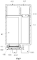
FIG. 4 is a structural view of an interior of a shell body of the atomization generator of the present invention; -
FIG. 5 is a sectional view ofFIG. 2 taken along line B-B; -
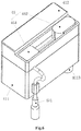
FIG. 6 is a structural view of the atomization generator of the present invention after a second shell cover is removed; -
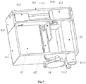
FIG. 7 is a sectional view ofFIG. 2 taken along line A-A; -
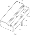
FIG. 8 is a first structural view of a first shell cover of the atomization generator of the present invention; -
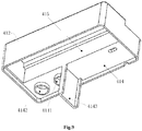
FIG. 9 is a second structural view of the first shell cover of the atomization generator of the present invention; and -
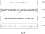
FIG. 10 is a flowchart of a method for controlling an atomization generator of the present invention. - 1: cabinet; 2: inner cylinder; 3: outer cylinder; 4: atomization generator; 41: shell; 411: shell body; 4111: air inlet; 4112: liquid inlet; 4113: mist outlet; 412: first shell cover; 413: second shell cover; 414: transverse rib; 4141: first communication hole; 4142: second communication hole; 4143: air blocking plate; 415: vertical rib; 416: flow stabilizing plate; 417: partition; 4171: notch; 42: atomization cavity; 43: installation cavity; 44: atomization module; 441: ultrasonic atomization sheet; 442: atomization sheet holder; 443: sealing member; 444: drive circuit board; 45: valve mechanism; 451: drive part; 452: sealing block; 46: connection pipe; 47: controller; 471: cable; 472: control wire; 48: fan; 5: drying module; 6: liquid inlet pipe; 7: mist outlet pipe; 8: solenoid valve; 9: control unit.
- Preferred embodiments of the present invention will be described below with reference to the accompanying drawings. It should be understood by those skilled in the art that these embodiments are only used to explain the technical principles of the present invention, and are not intended to limit the scope of protection of the present invention. For example, although this embodiment is described in conjunction with a drum washing machine, this is not intended to limit the scope of protection of the present invention. The present invention may also be applied to other clothing treatment apparatuses, such as a pulsator washing machine or a washing-drying integrated machine.
- It should be noted that in the description of the present invention, terms indicating directional or positional relationships, such as "center", "upper", "lower", "left", "right", "vertical", "horizontal", "inner", "outer" and the like, are based on the directional or positional relationships shown in the accompanying drawings. They are only used for ease of description, and do not indicate or imply that the device or element must have a specific orientation, or be constructed or operated in a specific orientation, and therefore they should not be considered as limitations to the present invention. In addition, terms "first", "second" and "third" are only used for descriptive purposes, and should not be understood as indicating or implying relative importance.
- In addition, it should also be noted that in the description of the present invention, unless otherwise clearly specified and defined, terms "install", "connect" and "connection" should be understood in a broad sense; for example, the connection may be a fixed connection, or may also be a detachable connection, or an integral connection; it may be a mechanical connection, or an electrical connection; it may be a direct connection, or an indirect connection implemented through an intermediate medium, or it may be an internal communication between two elements. For those skilled in the art, the specific meaning of the above terms in the present invention can be understood according to specific situations.
- First, referring to
FIGS. 1 to 4 , a drum washing machine of the present invention will be described.FIG. 1 is a schematic structural view of the drum washing machine of the present invention;FIG. 2 is a first outline view of an atomization generator of the present invention;FIG. 3 is a second outline view of the atomization generator of the present invention; andFIG. 4 is a structural view of an interior of a shell body of the atomization generator of the present invention. - As shown in
FIG. 1 , in order to solve the problems of complicated structure and poor accuracy of liquid level measurement existing in an existingatomization generator 4, the drum washing machine of the present invention mainly includes acabinet 1, as well as aninner cylinder 2, anouter cylinder 3, anatomization generator 4, adrying module 5 and acontrol unit 9, all of which are provided in thecabinet 1. Theinner cylinder 2 is configured to accommodate clothing, and thedrying module 5 is in circulative communication with theouter cylinder 3 to dry the clothing in theinner cylinder 2 by providing hot air flow to theouter cylinder 3 and theinner cylinder 2. Theatomization generator 4 communicates with a water source through aliquid inlet pipe 6 and asolenoid valve 8, and communicates with theouter cylinder 3 through amist outlet pipe 7. When theatomization generator 4 is working, the water source enters theatomization generator 4 through thesolenoid valve 8 and theliquid inlet pipe 6. After theatomization generator 4 atomizes the water into water mist, the water mist is sprayed to theinner cylinder 2 through themist outlet pipe 7 and the clothing in theinner cylinder 2 is treated. - With reference to
FIGS. 2 to 4 , theatomization generator 4 includes ashell 41, and anatomization module 44 capable of atomizing the liquid in anatomization cavity 42 into steam. Apartition 417 is provided in theshell 41. Thepartition 417 divides theshell 41 into theatomization cavity 42 and aninstallation cavity 43 that communicate with each other. Theatomization cavity 42 can contain the liquid. Theshell 41 is provided with anair inlet 4111, aliquid inlet 4112 and amist outlet 4113 that communicate with theatomization cavity 42. Theliquid inlet 4112 is connected to theliquid inlet pipe 6, and themist outlet 4113 is connected to themist outlet pipe 7. Theatomization module 44 includes anultrasonic atomization sheet 441, which can atomize the liquid in theatomization cavity 42 through vibration and detect a height of liquid level in theatomization cavity 42 through vibration. Acontroller 47 is provided in theinstallation cavity 43. Thecontroller 47 is connected to thecontrol unit 9 through acable 471, and is connected to theatomization module 44 through acontrol wire 472 to control start and stop of theultrasonic atomization sheet 441. - Through the above arrangement, the present invention greatly simplifies the structure of the
atomization generator 4, and improves the precision and accuracy of liquid level measurement. Specifically, by using theultrasonic atomization sheet 441 as the atomization element, the liquid level measurement function and the atomization function are integrated in theultrasonic atomization sheet 441, so that not only the height of liquid level in theatomization cavity 42 can be measured through vibration, but also the liquid in theatomization cavity 42 can be atomized, which greatly simplifies the structure of theatomization generator 4. Moreover, since the measurement principle of theultrasonic atomization sheet 441 determines that it is less affected by liquid density, viscosity, temperature and the like during the measurement, this measurement method can ensure the precision and accuracy of measurement. Further, by providing thepartition 417 in theshell 41, which divides theshell 41 into theatomization cavity 42 and theinstallation cavity 43, and by arranging thecontroller 47 which is connected to theultrasonic atomization sheet 441 in theinstallation cavity 43, when theatomization generator 4 of the present invention leaves the factory, thecontroller 47 and theultrasonic atomization sheet 441 are already assembled. Therefore, when assembling the drum washing machine, it is only required to install theatomization generator 4 to a set position inside the drum washing machine and insertedly connect thecontroller 47 to thecontrol unit 9 by using thecable 471. The assembly process is extremely convenient, which greatly simplifies the assembly process and improves the assembly efficiency. - The
atomization generator 4 will be described in detail below with reference toFIGS. 2 to 9 .FIG. 5 is a sectional view ofFIG. 2 taken along line B-B;FIG. 6 is a structural view of the atomization generator of the present invention after a second shell cover is removed;FIG. 7 is a sectional view ofFIG. 2 taken along line A-A;FIG. 8 is a first structural view of a first shell cover of the atomization generator of the present invention; andFIG. 9 is a second structural view of the first shell cover of the atomization generator of the present invention. - As shown in
FIGS. 2 to 4 , in a possible embodiment, theshell 41 includes ashell body 411, afirst shell cover 412, and asecond shell cover 413. Thepartition 417 is provided in theshell body 411, and thepartition 417 divides theshell body 411 into theatomization cavity 42 and theinstallation cavity 43 that communicate with each other. Theliquid inlet 4112 and themist outlet 4113 are provided on a bottom surface of theshell body 411 on a side corresponding to theatomization cavity 42, and theair inlet 4111 is provided on a side surface of theshell body 411 at a position corresponding to theinstallation cavity 43. Aflow stabilizing plate 416 extends upward from the bottom surface of theatomization cavity 42. Theflow stabilizing plate 416 is arranged between theliquid inlet 4112 and theultrasonic atomization sheet 441. One side of theflow stabilizing plate 416 is fixedly connected to an inner wall of theatomization cavity 42, and the other side of theflow stabilizing plate 416 extends to another inner wall of theatomization cavity 42 and forms a gap with this inner wall for the liquid to flow out. With reference toFIG. 5 , a bottom of theatomization cavity 42 is provided with a water-permeable hole (not shown in the figure), and theultrasonic atomization sheet 441 is provided outside theshell body 411 and is sealedly connected at the water-permeable hole by a sealingmember 443 in theatomization sheet holder 442 so that the liquid in theatomization cavity 42 can be atomized into water mist. Referring back toFIG. 4 , thecontroller 47 is provided in theinstallation cavity 43 at a position right facing theair inlet 4111, thepartition 417 has anotch 4171, and thenotch 4171 is provided corresponding to thecontroller 47 on one side of thepartition 417. Afan 48 is arranged between theair inlet 4111 and thecontroller 47. A suction port of thefan 48 is arranged corresponding to theair inlet 4111, and an exhaust port of thefan 48 is arranged toward thepartition 417, so that the air from outside theshell body 411 is introduced into theshell body 411 by thefan 48 during operation. After the air flows through thecontroller 47, most of the air reaches theatomization cavity 42 through thenotch 4171. - With reference to
FIGS. 6 to 9 , a communication cavity (not shown in the figure) independent from theatomization cavity 42 is also formed in theshell 41, theatomization cavity 42 communicates with the communication cavity through afirst communication hole 4141, and themist outlet 4113 communicates with the communication cavity through aconnection pipe 46 and asecond communication hole 4142, so that the air entering theatomization cavity 42 drives the steam obtained by atomization of theultrasonic atomization sheet 441 to sequentially pass through thefirst communication hole 4141, the communication cavity, thesecond communication hole 4142 and the connection pipe before being discharged from themist outlet 4113. That is, a complete air flow passage is formed between theair inlet 4111 and themist outlet 4113 through theinstallation cavity 43, thenotch 4171, theatomization cavity 42, thefirst communication hole 4141, the communication cavity, thesecond communication hole 4142 and the connection pipe, and the air flow passage flows through a part of thecontroller 47. Referring back toFIGS. 4 and5 , adrive circuit board 444 for driving theultrasonic atomization sheet 441 is also installed in theatomization sheet holder 442, and thecontroller 47 is connected to thedrive circuit board 444 and thefan 48 respectively to control theultrasonic atomization sheet 441 and start and stop of thefan 48 respectively. A bottom surface of theinstallation cavity 43 is provided with a wire-passing hole (not shown in the figure) that allows thecontrol wire 472 to pass through. One end of thecontrol wire 472 is connected to thedrive circuit board 444, and the other end is connected to thecontroller 47 through the wire-passing hole. - With reference to
FIGS. 8 and9 , in a possible embodiment, thefirst shell cover 412 is provided with atransverse rib 414 and avertical rib 415. Thetransverse rib 414 is fixedly connected to three successively adjacent inner side surfaces of thefirst shell cover 412, and thevertical rib 415 is fixedly connected to a top surface of thefirst shell cover 412 and two opposite ones of the above three successively adjacent inner side surfaces, so that thetransverse rib 414, thevertical rib 415 and the three successively adjacent inner side surfaces jointly enclose the aforementioned communication cavity, on which thesecond shell cover 413 can be arranged. With reference toFIGS. 4 ,7 and8 , thefirst communication hole 4141 and thesecond communication hole 4142 are provided on thetransverse rib 414 at positions corresponding to theatomization cavity 42 and themist outlet 4113. Theatomization cavity 42 is connected to the communication cavity through thefirst communication hole 4141, and themist outlet 4113 is connected to thesecond communication hole 4142 through theconnection pipe 46. Anair blocking plate 4143 also extends downward from a bottom surface of thetransverse rib 414, theair blocking plate 4143 extends into theatomization cavity 42, and is arranged corresponding to thenotch 4171. - With reference to
FIGS. 6 and7 , in a possible embodiment, avalve mechanism 45 is also provided in the communication cavity, and thevalve mechanism 45 is configured to able to seal thefirst communication hole 4141 and thesecond communication hole 4142 simultaneously. Thevalve mechanism 45 includes adrive part 451 and asealing block 452. Thecontroller 47 is connected to thedrive part 451 to control start and stop of thedrive part 451. Thedrive part 451 is connected to thesealing block 452 and can drive the sealingblock 452 to slide back and forth in the communication cavity under the control of thecontroller 47. For example, thedrive part 451 is an air cylinder, an electric cylinder or a linear motor, and an output shaft of thedrive part 451 is fixedly connected to thesealing block 452, thereby driving thesealing block 452 to slide in the communication cavity. A bottom surface of thesealing block 452 can cover thefirst communication hole 4141 and thesecond communication hole 4142 simultaneously, and a relatively good sealing is maintained after the covering. - The advantage of the above arrangement is that by using the
ultrasonic atomization sheet 441 as the atomization element, the principle of theultrasonic atomization sheet 441 can be used to realize the integration of the liquid level detection function and the atomization function, which greatly simplifies the structure of theatomization generator 4; moreover, the measurement principle of theultrasonic atomization sheet 441 determines that it is less affected by the density, viscosity, and temperature of the liquid during measurement, so the accuracy of liquid level measurement can be ensured. Theflow stabilizing plate 416 is provided in theatomization cavity 42 at a position corresponding to theliquid inlet 4112. Theliquid inlet 4112 and theultrasonic atomization sheet 441 are spaced apart by theflow stabilizing plate 416, so that when the liquid enters theatomization cavity 42, theflow stabilizing plate 416 can also effectively suppress the splash generated when the liquid enters theatomization cavity 42, reduce fluctuation of the liquid level caused by the impact of water flow, and further improve the accuracy of detecting the liquid level by theultrasonic atomization sheet 441. Theshell body 411 is divided into theatomization cavity 42 and theinstallation cavity 43 by thepartition 417, and thecontroller 47 is arranged in theinstallation cavity 43 and is connected to thedrive circuit board 444, thedrive part 451 and thefan 48 respectively, so that theatomization generator 4 of the present invention is highly integrated. Thecontroller 47 can control the start and stop of theultrasonic atomization sheet 441, thedrive part 451, and thefan 48 simultaneously, which avoids separate wirings of the above-mentioned components when assembling the washing machine, and improves the assembly efficiency. Thefan 48 is provided between thecontroller 47 and theair inlet 4111, the suction port of thefan 48 is arranged corresponding to theair inlet 4111, and the exhaust port of thefan 48 is arranged toward thepartition 417. Thepartition 417 is provided with thenotch 4171 at a position corresponding to thecontroller 47. When theatomization generator 4 is working, the airflow during the operation of theatomization generator 4 can also dissipate heat from thecontroller 47 when flowing through thecontroller 47, thereby improving the working life and working stability of thecontroller 47. - By arranging the communication cavity on the first cover and arranging the
mist outlet 4113 on the bottom surface of theshell body 411, and then by connecting themist outlet 4113 with thesecond communication hole 4142 by the connection pipe, a complete air flow passage is formed between theinstallation cavity 43, theatomization cavity 42, the communication cavity and the connection pipe, and in combination with the action of thefan 48, the discharge of water mist is made natural and strong. Themist outlet 4113 is arranged on the bottom surface of theshell 41 to facilitate the connection with themist outlet pipe 7 so that themist outlet pipe 7 can be connected to theouter cylinder 3 without bending, which shortens a spray stroke of the water mist and improves the spray effect of the water mist. Theair blocking plate 4143 extends from the bottom surface of thetransverse rib 414 in a way of corresponding to thenotch 4171, so that the wind blown by thefan 48 bypasses after passing through thenotch 4171, thereby improving the effect of carrying the water mist by the wind and achieving the purpose of rapid discharge of the water mist, thus avoiding a situation in which the wind blows out and the water mist remains in theatomization cavity 42. Theultrasonic atomization sheet 441 is sealedly arranged outside theshell body 411 through theatomization sheet holder 442, and the wire-passing hole is arranged in theinstallation cavity 43, so that the wiring of thecontrol wire 472 does not pass through theatomization cavity 42, thus avoiding safety problems caused by the contact of thecontrol wire 472 with water and improving the safety of theatomization generator 4. - The
ultrasonic atomization sheet 441 is used as the atomization element, and theatomization generator 4 uses high-frequency oscillation of electrons (the oscillation frequency is 1.7MHz or 2.4MHz and other frequencies exceeding the auditory range, and the oscillation of electrons has no harm to human and animals). Through the high-frequency resonance of the atomization sheet, the molecular structure of the liquid water is broken up to produce a naturally flowing water mist. The water is atomized into ultrafine particles of 1 to 100 microns, being uniform, without heating or adding any chemical reagents. As compared with the heating atomization method, energy is saved by 90%. In addition, a large amount of negative ions will be released during the atomization process, which will react electrostatically with smoke and dust floating in the air to precipitate them. At the same time, harmful substances such as formaldehyde, carbon monoxide, bacteria can be effectively removed, and micron-level water molecules can be adsorbed on the clothing faster, making the clothing caring experience better. - By providing the communication cavity in the
atomization generator 4 and providing thevalve mechanism 45 in the communication cavity, the operating safety of the washing machine can be greatly improved, and the humid and hot air can be effectively prevented from flowing back to theatomization generator 4 and the interior of the washing machine when thedrying module 5 is started, which would otherwise cause short-circuit of the electrical components due to wetting. Specifically, the communication cavity independent from theatomization cavity 42 is provided in theshell 41, and theatomization cavity 42 communicates with themist outlet 4113 through the communication cavity, so that the communication cavity becomes a passage way which must be passed through by the water mist for reaching themist outlet 4113 from theatomization cavity 42. Thevalve mechanism 45 is provided in the communication cavity, and thevalve mechanism 45 can seal thefirst communication hole 4141 and thesecond communication hole 4142, so that thevalve mechanism 45 can cut off the passage completely, thereby preventing the outside air from flowing back into theatomization generator 4 from themist outlet 4113; in particular, when thedrying module 5 of the washing machine is started, the humid air in the washing tub can be blocked from flowing back to theatomization generator 4 and then being discharged to the interior of the washing machine from theair inlet 4111. This prevents the occurrence of faults such as short-circuit of the electrical components in theatomization generator 4 and the washing machine due to wetting, which greatly improves the operational safety of the washing machine. Moreover, the above arrangement has high feasibility and outstanding effect, which is advantageous for large-scale promotion and use. - It should be noted that the above preferred embodiments are only used to illustrate the principle of the present invention, and are not intended to limit the scope of protection of the present invention. Without departing from the principle of the present invention, those skilled in the art can adjust the above arrangements so that the present invention can be applied to a more specific application scene.
- For example, in an alternative embodiment, the arrangement of the
valve mechanism 45 is not invariable, and those skilled in the art may adjust it as long as it can seal thefirst communication hole 4141 and/or thesecond communication hole 4142. For example, an ordinary motor may also be selected as thedrive part 451, and a transmission member is added between thedrive part 451 and thesealing block 452 to complete the reciprocating sliding of thesealing block 452. For example, the transmission member may be a ball screw. For another example, the sealingblock 452 may also be configured to seal only one of thefirst communication hole 4141 and thesecond communication hole 4142, which can also achieve the function of preventing the backflow of humid and hot air. - For another example, in another alternative embodiment, the
fan 48 may not be provided on theshell body 411, but thefan 48 is provided inside theshell body 411 or at other positions, as long as the position enables the water mist to be effectively discharged from theatomization cavity 42. For example, thefan 48 may also be arranged on themist outlet pipe 7, etc. - For another example, in another alternative embodiment, those skilled in the art can may adjust the position of arranging the communication cavity, as long as the arrangement of the communication cavity can make the communication cavity independent from the
atomization cavity 42. For example, the communication cavity may also be provided inside theshell body 411 instead of being provided on thefirst shell cover 412. - For another example, in another alternative embodiment, the position of the
mist outlet 4113 is not unique, and it may also be arranged on the side wall of theshell body 411, on thefirst shell cover 412 or on thesecond shell cover 413, etc. Correspondingly, it is only necessary to adjust the positions of arranging thesecond communication hole 4142 and theconnection pipe 46. This adjustment of the position of arranging themist outlet 4113 does not deviate from the principle of the present invention. - For another example, in another alternative embodiment, the way and position of arranging the
flow stabilizing plate 416 can be adjusted, as long as the adjustment can reduce fluctuation of the liquid level when the liquid enters theatomization cavity 42. For example, theflow stabilizing plate 416 may also be arranged on the inner wall of theatomization cavity 42 or on the first shell cover, and a certain gap is left between the lower side and theatomization cavity 42. - Of course, the above alternative embodiments, as well as the alternative embodiments and the preferred embodiments, can also be used in combination with each other, so as to obtain new embodiments that are suitable for a more specific application scene.
- The control method for the drum washing machine of the present invention will be described below with reference to
FIG. 10 , which is a flowchart of the control method for the drum washing machine of the present invention. - As shown in
FIG. 10 , the control method for the drum washing machine of the present invention mainly includes: - S100: controlling the
solenoid valve 8 to be opened. For example, after the user selects related functions such as steam washing of the drum washing machine, thecontrol unit 9 controls thesolenoid valve 8 to be opened to inject water into theatomization cavity 42; - S200: at the same time as the
solenoid valve 8 is opened, controlling theultrasonic atomization sheet 441 to vibrate so as to detect a height of the liquid level in theatomization cavity 42. For example, at the same time as thesolenoid valve 8 is opened, thecontroller 47 controls thedrive circuit board 444 to be connected, thedrive circuit board 444 drives theultrasonic atomization sheet 441 to work, and theultrasonic atomization sheet 441 detects the height of the liquid level in theatomization cavity 42 through vibration; of course, the detection timing of theultrasonic atomization sheet 441 can be adjusted; for example, after thesolenoid valve 8 has been opened for a certain period of time, theultrasonic atomization sheet 441 is controlled to vibrate to detect the height of the liquid level in theatomization cavity 42. - S300: judging whether the height of the liquid level reaches a set height. For example, the set height is a height calculated based on the weight of the clothing or a height set in advance. At the same time as the
ultrasonic atomization sheet 441 detects the height of the liquid level, it is judged whether the height of the liquid level reaches the set height; - S400: selectively controlling the
solenoid valve 8 to be closed based on a judgment result; for example, if the height of the liquid level reaches the set height, thesolenoid valve 8 is controlled to be closed, and if the height of the liquid level does not reach the set height, theultrasonic atomization sheet 441 continuously detects the height of the liquid level. - Through the above control method, the drum washing machine of the present invention can use the
ultrasonic atomization sheet 441 to detect the height of the liquid level, which improves the accuracy of liquid level measurement, and thereby improves the control accuracy of the drum washing machine. - Hereinafter, referring to
FIGS. 1 to 10 , a working process of the drum washing machine in a possible embodiment will be described. - In a possible embodiment, after the user selects the steam washing option on a control panel of the drum washing machine, the
solenoid valve 8 is opened, and water enters theatomization cavity 42. Theultrasonic atomization sheet 441 first detects the height of the liquid level. After the liquid level reaches the set height, thesolenoid valve 8 is closed, and thecontroller 47 controls thedrive circuit board 444 and thefan 48 to start at the same time. Theultrasonic atomization sheet 441 atomizes the water in theatomizing cavity 42, and at the same time, thefan 48 introduces the outside air into theinstallation cavity 43 through theair inlet 4111. After flowing through thecontroller 47 to cool thecontroller 47, the air flows into theatomization cavity 42 through thenotch 4171, and drives the steam generated by atomization of the ultrasonic atomization sheet to sequentially pass through thefirst communication hole 4141, the communication cavity, thesecond communication hole 4142, the connection pipe, themist outlet 4113 and themist outlet pipe 7 before being sprayed into theinner cylinder 2 to treat the clothing. - Hitherto, the technical solutions of the present invention have been described in conjunction with the preferred embodiments shown in the accompanying drawings, but it is easily understood by those skilled in the art that the scope of protection of the present invention is obviously not limited to these specific embodiments. Without departing from the principles of the present invention, those skilled in the art can make equivalent changes or replacements to relevant technical features, and all the technical solutions after these changes or replacements will fall within the scope of protection of the present invention.
Claims (10)
- An atomization generator, comprising a shell and an atomization module; wherein the shell is provided therein with an atomization cavity capable of containing a liquid, and the shell is provided thereon with a liquid inlet, an air inlet and a mist outlet, all of which communicate with the atomization cavity; and wherein the atomization module comprises an ultrasonic atomization sheet, and the atomization module is configured to be capable of atomizing the liquid in the atomization cavity through vibration of the ultrasonic atomization sheet and detecting a height of liquid level in the atomization cavity through the vibration.
- The atomization generator according to claim 1, wherein a water-permeable hole is provided at a bottom of the shell, the atomization module further comprises an atomization sheet holder, and the ultrasonic atomization sheet is sealedly fixed to an outer part of the shell through the atomization sheet holder at a position corresponding to the water-permeable hole.
- The atomization generator according to claim 2, wherein a partition is provided in the shell, and the partition divides the shell into an installation cavity and the atomization cavity; and wherein the installation cavity is provided therein with a controller, the atomization module further comprises a drive circuit board for driving the ultrasonic atomization sheet, the drive circuit board is installed on the atomization sheet holder, and the controller is connected to the drive circuit board.
- The atomization generator according to claim 1, wherein the liquid inlet is provided on a bottom surface of the atomization cavity, a flow stabilizing plate corresponding to the liquid inlet is further provided in the atomization cavity, and the flow stabilizing plate isolates the liquid inlet from the ultrasonic atomization sheet.
- The atomization generator according to claim 4, wherein the flow stabilizing plate is formed by extending upward from the bottom surface of the atomization cavity, one side of the flow stabilizing plate is fixedly connected to one inner wall of the atomization cavity, and the other side of the flow stabilizing plate extends to another inner wall of the atomization cavity and forms a gap with said other inner wall.
- The atomization generator according to claim 3, wherein the air inlet is arranged on the shell at a position corresponding to the installation cavity; and/or
a fan is equipped at the air inlet, and the controller is further connected to the fan to control start and stop of the fan. - The atomization generator according to claim 3, wherein a communication cavity is further provided in the shell, the atomization cavity communicates with the communication cavity through a first communication hole, and the mist outlet communicates with the communication cavity through a second communication hole.
- The atomization generator according to claim 7, wherein the mist outlet is arranged on a bottom surface of the shell, the atomization generator further comprises a connection pipe, and the mist outlet communicates with the second communication hole through the connection pipe; and/or
a valve mechanism is further provided in the communication cavity, the valve mechanism is configured to be capable of sealing the first communication hole and/or the second communication hole, and the controller is connected to the valve mechanism to control opening and closing of the valve mechanism. - A clothing treatment apparatus, comprising a cabinet and a washing tub arranged in the cabinet; wherein the clothing treatment apparatus further comprises the atomization generator according to any one of claims 1 to 8, the liquid inlet communicates with a water source through a liquid inlet pipe and a solenoid valve, and the mist outlet communicates with the washing tub through a mist outlet pipe.
- A method for controlling a clothing treatment apparatus, wherein the clothing treatment apparatus comprises a cabinet, as well as a washing tub and an atomization generator that are arranged in the cabinet; the atomization generator comprises a shell and an atomization module, the shell is provided therein with an atomization cavity capable of containing a liquid, and the shell is provided thereon with a liquid inlet, an air inlet and a mist outlet, all of which communicate with the atomization cavity; the liquid inlet communicates with a water source through a liquid inlet pipe and a solenoid valve, the mist outlet communicates with the washing tub through a mist outlet pipe, and the atomization module comprises an ultrasonic atomization sheet which is capable of detecting a liquid level of the liquid in the atomization cavity through vibration and atomizing the liquid in the atomization cavity;
the control method comprising:controlling the solenoid valve to be opened;at the same time as or after the solenoid valve is opened, controlling the ultrasonic atomization sheet to vibrate so as to detect a height of the liquid level in the atomization cavity;judging whether the height of the liquid level reaches a set height; andselectively controlling the solenoid valve to be closed based on a judgment result.
Applications Claiming Priority (2)
| Application Number | Priority Date | Filing Date | Title |
|---|---|---|---|
| CN201910165011.8A CN111663286B (en) | 2019-03-05 | 2019-03-05 | Atomizer generator, laundry treatment equipment and control method thereof |
| PCT/CN2020/077457 WO2020177671A1 (en) | 2019-03-05 | 2020-03-02 | Atomising generator, clothing treatment device, and control method therefor |
Publications (3)
| Publication Number | Publication Date |
|---|---|
| EP3936652A1 true EP3936652A1 (en) | 2022-01-12 |
| EP3936652A4 EP3936652A4 (en) | 2022-05-18 |
| EP3936652B1 EP3936652B1 (en) | 2023-12-20 |
Family
ID=72337644
Family Applications (1)
| Application Number | Title | Priority Date | Filing Date |
|---|---|---|---|
| EP20766633.0A Active EP3936652B1 (en) | 2019-03-05 | 2020-03-02 | Atomising generator, clothing treatment device, and control method therefor |
Country Status (5)
| Country | Link |
|---|---|
| US (1) | US12043946B2 (en) |
| EP (1) | EP3936652B1 (en) |
| JP (1) | JP7228710B2 (en) |
| CN (1) | CN111663286B (en) |
| WO (1) | WO2020177671A1 (en) |
Families Citing this family (2)
| Publication number | Priority date | Publication date | Assignee | Title |
|---|---|---|---|---|
| US11585030B1 (en) * | 2021-12-11 | 2023-02-21 | Eve Street Designs Pty Ltd. | Portable plunger-wash bag apparatus and method of use to clean laundry |
| CN114808305B (en) * | 2022-05-17 | 2024-05-17 | 北京奥润联创微电子科技开发有限公司 | Ultrasonic atomizing coating head |
Family Cites Families (27)
| Publication number | Priority date | Publication date | Assignee | Title |
|---|---|---|---|---|
| FR2746656B1 (en) * | 1996-03-26 | 1999-05-28 | System Assistance Medical | PRESSURE SENSOR NEBULIZER |
| US6543701B1 (en) * | 2001-12-21 | 2003-04-08 | Tung-Huang Ho | Pocket-type ultrasonic atomizer structure |
| US20060188646A1 (en) | 2005-02-21 | 2006-08-24 | Yun Ju Y | System and method for detecting remaining amount of precursor in vessel during CVD process |
| JP2008539890A (en) * | 2005-05-05 | 2008-11-20 | プルマトリックス インコーポレイテッド | Ultrasonic aerosol generator |
| CN2884012Y (en) | 2006-02-08 | 2007-03-28 | 北京亚都科技股份有限公司 | Ultrasonic mist humidifier |
| CN100503945C (en) * | 2006-06-06 | 2009-06-24 | 南京乐金熊猫电器有限公司 | Steam generator for drum washing machine |
| JP2009072653A (en) | 2007-09-19 | 2009-04-09 | Panasonic Corp | Ultrasonic atomizer |
| JP4935744B2 (en) * | 2008-04-10 | 2012-05-23 | パナソニック株式会社 | Washing machine |
| CN201212831Y (en) * | 2008-06-18 | 2009-03-25 | 山东电力中心医院 | Atomizing tank liquid level measurement and display device for medical ultrasonic atomizer |
| CN101660158A (en) * | 2008-08-27 | 2010-03-03 | 鸿富锦精密工业(深圳)有限公司 | Film preparation device |
| CN101949578B (en) | 2010-10-27 | 2012-07-18 | 法雷奥汽车空调湖北有限公司 | Automobile air-conditioner condensed water cold energy recycling device |
| CN202539014U (en) * | 2012-03-19 | 2012-11-21 | 宋志辉 | Ultrasonic nebulizer |
| DE102012213934A1 (en) * | 2012-08-07 | 2014-02-13 | BSH Bosch und Siemens Hausgeräte GmbH | Washing machine with apparatus for producing water droplets and method for its operation |
| CN203683967U (en) * | 2014-01-20 | 2014-07-02 | 徐万群 | Steam and dry iron with ironing bottom plate capable of conveniently stretching out and drawing back |
| KR102227372B1 (en) * | 2014-04-21 | 2021-03-11 | 엘지전자 주식회사 | Laundry washing method |
| JP2016016230A (en) * | 2014-07-10 | 2016-02-01 | パナソニックIpマネジメント株式会社 | Cloth processing equipment |
| CN104374032A (en) * | 2014-09-30 | 2015-02-25 | 潘浩斌 | Novel ultrasonic humidifier |
| CN106403145A (en) * | 2015-08-13 | 2017-02-15 | 陈楚娇 | Ultrasonic humidifier |
| CN205262547U (en) * | 2015-12-31 | 2016-05-25 | 深圳飞安瑞电子科技有限公司 | A lack of water detection circuitry for ultrasonic atomization ware |
| FR3050146B1 (en) * | 2016-04-18 | 2019-04-19 | Valeo Systemes Thermiques | AIR REFRESHING DEVICE FOR VEHICLE AND HEATING, VENTILATION AND / OR AIR CONDITIONING SYSTEM THEREOF |
| WO2018050540A1 (en) | 2016-09-16 | 2018-03-22 | BSH Hausgeräte GmbH | Household appliance with an aerosol generator and method for operating the same |
| CN106524373B (en) * | 2016-11-16 | 2022-04-01 | 广州奥迪威传感应用科技有限公司 | Humidifying method, humidifying device and aromatherapy machine |
| CN206786891U (en) | 2017-06-08 | 2017-12-22 | 郑宗彪 | A kind of ceiling mounting type ultrasonic purification device |
| CN107700143A (en) * | 2017-11-10 | 2018-02-16 | 浙江大学 | Pinpoint ultrasonic microbubble joint clothes washer-dryer and its method |
| CN108645485A (en) * | 2018-05-30 | 2018-10-12 | 广东奥迪威传感科技股份有限公司 | A kind of level testing methods and device for atomizer |
| CN208536233U (en) * | 2018-05-30 | 2019-02-22 | 广东奥迪威传感科技股份有限公司 | an atomizer |
| CN210117537U (en) * | 2019-03-05 | 2020-02-28 | 青岛海尔洗衣机有限公司 | Atomizer, Clothes Treatment Equipment |
-
2019
- 2019-03-05 CN CN201910165011.8A patent/CN111663286B/en active Active
-
2020
- 2020-03-02 US US17/436,257 patent/US12043946B2/en active Active
- 2020-03-02 WO PCT/CN2020/077457 patent/WO2020177671A1/en not_active Ceased
- 2020-03-02 EP EP20766633.0A patent/EP3936652B1/en active Active
- 2020-03-02 JP JP2021551850A patent/JP7228710B2/en active Active
Also Published As
| Publication number | Publication date |
|---|---|
| JP2022522500A (en) | 2022-04-19 |
| JP7228710B2 (en) | 2023-02-24 |
| US12043946B2 (en) | 2024-07-23 |
| CN111663286A (en) | 2020-09-15 |
| US20220154384A1 (en) | 2022-05-19 |
| CN111663286B (en) | 2023-12-05 |
| WO2020177671A1 (en) | 2020-09-10 |
| EP3936652B1 (en) | 2023-12-20 |
| EP3936652A4 (en) | 2022-05-18 |
Similar Documents
| Publication | Publication Date | Title |
|---|---|---|
| EP3916146B1 (en) | Atomizing generator and clothes treatment apparatus comprising the atomizing generator | |
| US11807977B2 (en) | Atomizing generator and clothes treatment apparatus comprising the atomizing generator | |
| CN111663302B (en) | Atomization device for clothing treatment equipment, clothing treatment equipment and control method | |
| EP2319979B1 (en) | Washing and drying machine | |
| EP3936652B1 (en) | Atomising generator, clothing treatment device, and control method therefor | |
| TWI422722B (en) | Laundry dryer | |
| CN106164358B (en) | Hand-held clothes treatment device | |
| CN210117537U (en) | Atomizer, Clothes Treatment Equipment | |
| CN111663281B (en) | Atomizer generator, laundry treatment equipment and control method thereof | |
| CN210117533U (en) | Atomizer, Clothes Treatment Equipment | |
| CN111076409A (en) | Silencer for air conditioner, window type air conditioner and control method | |
| CN114508887A (en) | Embedded refrigerator | |
| JP4809065B2 (en) | Bathroom heating device and bathroom system with mist generation function | |
| CN210117540U (en) | Pulsator washing machine | |
| JP2004028411A (en) | Minus ion generator | |
| JP2021527542A (en) | Clothes processing equipment | |
| JP5306148B2 (en) | Washing and drying machine | |
| CN115874430B (en) | Garment steamer and host thereof | |
| CN210787810U (en) | Atomizing device and laundry treating apparatus having the same | |
| CN111663288A (en) | pulsator washing machine | |
| CN110732447B (en) | Atomizing device and washing machine | |
| CN218961399U (en) | Aromatherapy instrument | |
| CN216786563U (en) | Champignon device and clothing care apparatus | |
| JP2005124768A (en) | Detection electrode device | |
| KR20020035689A (en) | A diffuser driving apparatus of indoor-unit for air conditioner |
Legal Events
| Date | Code | Title | Description |
|---|---|---|---|
| STAA | Information on the status of an ep patent application or granted ep patent |
Free format text: STATUS: THE INTERNATIONAL PUBLICATION HAS BEEN MADE |
|
| PUAI | Public reference made under article 153(3) epc to a published international application that has entered the european phase |
Free format text: ORIGINAL CODE: 0009012 |
|
| STAA | Information on the status of an ep patent application or granted ep patent |
Free format text: STATUS: REQUEST FOR EXAMINATION WAS MADE |
|
| 17P | Request for examination filed |
Effective date: 20210907 |
|
| AK | Designated contracting states |
Kind code of ref document: A1 Designated state(s): AL AT BE BG CH CY CZ DE DK EE ES FI FR GB GR HR HU IE IS IT LI LT LU LV MC MK MT NL NO PL PT RO RS SE SI SK SM TR |
|
| A4 | Supplementary search report drawn up and despatched |
Effective date: 20220414 |
|
| RIC1 | Information provided on ipc code assigned before grant |
Ipc: D06F 39/08 20060101ALI20220408BHEP Ipc: D06F 23/02 20060101ALI20220408BHEP Ipc: D06F 33/46 20200101ALI20220408BHEP Ipc: D06F 17/12 20060101AFI20220408BHEP |
|
| DAV | Request for validation of the european patent (deleted) | ||
| DAX | Request for extension of the european patent (deleted) | ||
| GRAP | Despatch of communication of intention to grant a patent |
Free format text: ORIGINAL CODE: EPIDOSNIGR1 |
|
| STAA | Information on the status of an ep patent application or granted ep patent |
Free format text: STATUS: GRANT OF PATENT IS INTENDED |
|
| INTG | Intention to grant announced |
Effective date: 20230725 |
|
| GRAS | Grant fee paid |
Free format text: ORIGINAL CODE: EPIDOSNIGR3 |
|
| GRAA | (expected) grant |
Free format text: ORIGINAL CODE: 0009210 |
|
| STAA | Information on the status of an ep patent application or granted ep patent |
Free format text: STATUS: THE PATENT HAS BEEN GRANTED |
|
| AK | Designated contracting states |
Kind code of ref document: B1 Designated state(s): AL AT BE BG CH CY CZ DE DK EE ES FI FR GB GR HR HU IE IS IT LI LT LU LV MC MK MT NL NO PL PT RO RS SE SI SK SM TR |
|
| REG | Reference to a national code |
Ref country code: GB Ref legal event code: FG4D |
|
| REG | Reference to a national code |
Ref country code: CH Ref legal event code: EP |
|
| REG | Reference to a national code |
Ref country code: DE Ref legal event code: R096 Ref document number: 602020023128 Country of ref document: DE |
|
| REG | Reference to a national code |
Ref country code: IE Ref legal event code: FG4D |
|
| PG25 | Lapsed in a contracting state [announced via postgrant information from national office to epo] |
Ref country code: GR Free format text: LAPSE BECAUSE OF FAILURE TO SUBMIT A TRANSLATION OF THE DESCRIPTION OR TO PAY THE FEE WITHIN THE PRESCRIBED TIME-LIMIT Effective date: 20240321 |
|
| REG | Reference to a national code |
Ref country code: LT Ref legal event code: MG9D |
|
| PG25 | Lapsed in a contracting state [announced via postgrant information from national office to epo] |
Ref country code: LT Free format text: LAPSE BECAUSE OF FAILURE TO SUBMIT A TRANSLATION OF THE DESCRIPTION OR TO PAY THE FEE WITHIN THE PRESCRIBED TIME-LIMIT Effective date: 20231220 |
|
| REG | Reference to a national code |
Ref country code: NL Ref legal event code: MP Effective date: 20231220 |
|
| PG25 | Lapsed in a contracting state [announced via postgrant information from national office to epo] |
Ref country code: ES Free format text: LAPSE BECAUSE OF FAILURE TO SUBMIT A TRANSLATION OF THE DESCRIPTION OR TO PAY THE FEE WITHIN THE PRESCRIBED TIME-LIMIT Effective date: 20231220 |
|
| PG25 | Lapsed in a contracting state [announced via postgrant information from national office to epo] |
Ref country code: LT Free format text: LAPSE BECAUSE OF FAILURE TO SUBMIT A TRANSLATION OF THE DESCRIPTION OR TO PAY THE FEE WITHIN THE PRESCRIBED TIME-LIMIT Effective date: 20231220 Ref country code: GR Free format text: LAPSE BECAUSE OF FAILURE TO SUBMIT A TRANSLATION OF THE DESCRIPTION OR TO PAY THE FEE WITHIN THE PRESCRIBED TIME-LIMIT Effective date: 20240321 Ref country code: FI Free format text: LAPSE BECAUSE OF FAILURE TO SUBMIT A TRANSLATION OF THE DESCRIPTION OR TO PAY THE FEE WITHIN THE PRESCRIBED TIME-LIMIT Effective date: 20231220 Ref country code: ES Free format text: LAPSE BECAUSE OF FAILURE TO SUBMIT A TRANSLATION OF THE DESCRIPTION OR TO PAY THE FEE WITHIN THE PRESCRIBED TIME-LIMIT Effective date: 20231220 Ref country code: BG Free format text: LAPSE BECAUSE OF FAILURE TO SUBMIT A TRANSLATION OF THE DESCRIPTION OR TO PAY THE FEE WITHIN THE PRESCRIBED TIME-LIMIT Effective date: 20240320 |
|
| REG | Reference to a national code |
Ref country code: AT Ref legal event code: MK05 Ref document number: 1642517 Country of ref document: AT Kind code of ref document: T Effective date: 20231220 |
|
| PG25 | Lapsed in a contracting state [announced via postgrant information from national office to epo] |
Ref country code: NL Free format text: LAPSE BECAUSE OF FAILURE TO SUBMIT A TRANSLATION OF THE DESCRIPTION OR TO PAY THE FEE WITHIN THE PRESCRIBED TIME-LIMIT Effective date: 20231220 |
|
| PG25 | Lapsed in a contracting state [announced via postgrant information from national office to epo] |
Ref country code: SE Free format text: LAPSE BECAUSE OF FAILURE TO SUBMIT A TRANSLATION OF THE DESCRIPTION OR TO PAY THE FEE WITHIN THE PRESCRIBED TIME-LIMIT Effective date: 20231220 Ref country code: RS Free format text: LAPSE BECAUSE OF FAILURE TO SUBMIT A TRANSLATION OF THE DESCRIPTION OR TO PAY THE FEE WITHIN THE PRESCRIBED TIME-LIMIT Effective date: 20231220 Ref country code: NO Free format text: LAPSE BECAUSE OF FAILURE TO SUBMIT A TRANSLATION OF THE DESCRIPTION OR TO PAY THE FEE WITHIN THE PRESCRIBED TIME-LIMIT Effective date: 20240320 Ref country code: NL Free format text: LAPSE BECAUSE OF FAILURE TO SUBMIT A TRANSLATION OF THE DESCRIPTION OR TO PAY THE FEE WITHIN THE PRESCRIBED TIME-LIMIT Effective date: 20231220 Ref country code: LV Free format text: LAPSE BECAUSE OF FAILURE TO SUBMIT A TRANSLATION OF THE DESCRIPTION OR TO PAY THE FEE WITHIN THE PRESCRIBED TIME-LIMIT Effective date: 20231220 Ref country code: HR Free format text: LAPSE BECAUSE OF FAILURE TO SUBMIT A TRANSLATION OF THE DESCRIPTION OR TO PAY THE FEE WITHIN THE PRESCRIBED TIME-LIMIT Effective date: 20231220 |
|
| PG25 | Lapsed in a contracting state [announced via postgrant information from national office to epo] |
Ref country code: IS Free format text: LAPSE BECAUSE OF FAILURE TO SUBMIT A TRANSLATION OF THE DESCRIPTION OR TO PAY THE FEE WITHIN THE PRESCRIBED TIME-LIMIT Effective date: 20240420 |
|
| PG25 | Lapsed in a contracting state [announced via postgrant information from national office to epo] |
Ref country code: CZ Free format text: LAPSE BECAUSE OF FAILURE TO SUBMIT A TRANSLATION OF THE DESCRIPTION OR TO PAY THE FEE WITHIN THE PRESCRIBED TIME-LIMIT Effective date: 20231220 Ref country code: AT Free format text: LAPSE BECAUSE OF FAILURE TO SUBMIT A TRANSLATION OF THE DESCRIPTION OR TO PAY THE FEE WITHIN THE PRESCRIBED TIME-LIMIT Effective date: 20231220 |
|
| PG25 | Lapsed in a contracting state [announced via postgrant information from national office to epo] |
Ref country code: SK Free format text: LAPSE BECAUSE OF FAILURE TO SUBMIT A TRANSLATION OF THE DESCRIPTION OR TO PAY THE FEE WITHIN THE PRESCRIBED TIME-LIMIT Effective date: 20231220 |
|
| PG25 | Lapsed in a contracting state [announced via postgrant information from national office to epo] |
Ref country code: SM Free format text: LAPSE BECAUSE OF FAILURE TO SUBMIT A TRANSLATION OF THE DESCRIPTION OR TO PAY THE FEE WITHIN THE PRESCRIBED TIME-LIMIT Effective date: 20231220 Ref country code: SK Free format text: LAPSE BECAUSE OF FAILURE TO SUBMIT A TRANSLATION OF THE DESCRIPTION OR TO PAY THE FEE WITHIN THE PRESCRIBED TIME-LIMIT Effective date: 20231220 Ref country code: RO Free format text: LAPSE BECAUSE OF FAILURE TO SUBMIT A TRANSLATION OF THE DESCRIPTION OR TO PAY THE FEE WITHIN THE PRESCRIBED TIME-LIMIT Effective date: 20231220 Ref country code: IS Free format text: LAPSE BECAUSE OF FAILURE TO SUBMIT A TRANSLATION OF THE DESCRIPTION OR TO PAY THE FEE WITHIN THE PRESCRIBED TIME-LIMIT Effective date: 20240420 Ref country code: EE Free format text: LAPSE BECAUSE OF FAILURE TO SUBMIT A TRANSLATION OF THE DESCRIPTION OR TO PAY THE FEE WITHIN THE PRESCRIBED TIME-LIMIT Effective date: 20231220 Ref country code: CZ Free format text: LAPSE BECAUSE OF FAILURE TO SUBMIT A TRANSLATION OF THE DESCRIPTION OR TO PAY THE FEE WITHIN THE PRESCRIBED TIME-LIMIT Effective date: 20231220 Ref country code: AT Free format text: LAPSE BECAUSE OF FAILURE TO SUBMIT A TRANSLATION OF THE DESCRIPTION OR TO PAY THE FEE WITHIN THE PRESCRIBED TIME-LIMIT Effective date: 20231220 |
|
| PG25 | Lapsed in a contracting state [announced via postgrant information from national office to epo] |
Ref country code: PT Free format text: LAPSE BECAUSE OF FAILURE TO SUBMIT A TRANSLATION OF THE DESCRIPTION OR TO PAY THE FEE WITHIN THE PRESCRIBED TIME-LIMIT Effective date: 20240422 Ref country code: PL Free format text: LAPSE BECAUSE OF FAILURE TO SUBMIT A TRANSLATION OF THE DESCRIPTION OR TO PAY THE FEE WITHIN THE PRESCRIBED TIME-LIMIT Effective date: 20231220 |
|
| PG25 | Lapsed in a contracting state [announced via postgrant information from national office to epo] |
Ref country code: PT Free format text: LAPSE BECAUSE OF FAILURE TO SUBMIT A TRANSLATION OF THE DESCRIPTION OR TO PAY THE FEE WITHIN THE PRESCRIBED TIME-LIMIT Effective date: 20240422 Ref country code: PL Free format text: LAPSE BECAUSE OF FAILURE TO SUBMIT A TRANSLATION OF THE DESCRIPTION OR TO PAY THE FEE WITHIN THE PRESCRIBED TIME-LIMIT Effective date: 20231220 |
|
| REG | Reference to a national code |
Ref country code: DE Ref legal event code: R097 Ref document number: 602020023128 Country of ref document: DE |
|
| PG25 | Lapsed in a contracting state [announced via postgrant information from national office to epo] |
Ref country code: DK Free format text: LAPSE BECAUSE OF FAILURE TO SUBMIT A TRANSLATION OF THE DESCRIPTION OR TO PAY THE FEE WITHIN THE PRESCRIBED TIME-LIMIT Effective date: 20231220 |
|
| PLBE | No opposition filed within time limit |
Free format text: ORIGINAL CODE: 0009261 |
|
| STAA | Information on the status of an ep patent application or granted ep patent |
Free format text: STATUS: NO OPPOSITION FILED WITHIN TIME LIMIT |
|
| PG25 | Lapsed in a contracting state [announced via postgrant information from national office to epo] |
Ref country code: SI Free format text: LAPSE BECAUSE OF FAILURE TO SUBMIT A TRANSLATION OF THE DESCRIPTION OR TO PAY THE FEE WITHIN THE PRESCRIBED TIME-LIMIT Effective date: 20231220 |
|
| PG25 | Lapsed in a contracting state [announced via postgrant information from national office to epo] |
Ref country code: SI Free format text: LAPSE BECAUSE OF FAILURE TO SUBMIT A TRANSLATION OF THE DESCRIPTION OR TO PAY THE FEE WITHIN THE PRESCRIBED TIME-LIMIT Effective date: 20231220 Ref country code: DK Free format text: LAPSE BECAUSE OF FAILURE TO SUBMIT A TRANSLATION OF THE DESCRIPTION OR TO PAY THE FEE WITHIN THE PRESCRIBED TIME-LIMIT Effective date: 20231220 |
|
| REG | Reference to a national code |
Ref country code: CH Ref legal event code: PL |
|
| PG25 | Lapsed in a contracting state [announced via postgrant information from national office to epo] |
Ref country code: LU Free format text: LAPSE BECAUSE OF NON-PAYMENT OF DUE FEES Effective date: 20240302 |
|
| PG25 | Lapsed in a contracting state [announced via postgrant information from national office to epo] |
Ref country code: MC Free format text: LAPSE BECAUSE OF FAILURE TO SUBMIT A TRANSLATION OF THE DESCRIPTION OR TO PAY THE FEE WITHIN THE PRESCRIBED TIME-LIMIT Effective date: 20231220 |
|
| 26N | No opposition filed |
Effective date: 20240923 |
|
| GBPC | Gb: european patent ceased through non-payment of renewal fee |
Effective date: 20240320 |
|
| PG25 | Lapsed in a contracting state [announced via postgrant information from national office to epo] |
Ref country code: MC Free format text: LAPSE BECAUSE OF FAILURE TO SUBMIT A TRANSLATION OF THE DESCRIPTION OR TO PAY THE FEE WITHIN THE PRESCRIBED TIME-LIMIT Effective date: 20231220 Ref country code: LU Free format text: LAPSE BECAUSE OF NON-PAYMENT OF DUE FEES Effective date: 20240302 |
|
| REG | Reference to a national code |
Ref country code: BE Ref legal event code: MM Effective date: 20240331 |
|
| PG25 | Lapsed in a contracting state [announced via postgrant information from national office to epo] |
Ref country code: BE Free format text: LAPSE BECAUSE OF NON-PAYMENT OF DUE FEES Effective date: 20240331 |
|
| PG25 | Lapsed in a contracting state [announced via postgrant information from national office to epo] |
Ref country code: GB Free format text: LAPSE BECAUSE OF NON-PAYMENT OF DUE FEES Effective date: 20240320 |
|
| PG25 | Lapsed in a contracting state [announced via postgrant information from national office to epo] |
Ref country code: FR Free format text: LAPSE BECAUSE OF NON-PAYMENT OF DUE FEES Effective date: 20240331 |
|
| PG25 | Lapsed in a contracting state [announced via postgrant information from national office to epo] |
Ref country code: IE Free format text: LAPSE BECAUSE OF NON-PAYMENT OF DUE FEES Effective date: 20240302 |
|
| PG25 | Lapsed in a contracting state [announced via postgrant information from national office to epo] |
Ref country code: IE Free format text: LAPSE BECAUSE OF NON-PAYMENT OF DUE FEES Effective date: 20240302 Ref country code: GB Free format text: LAPSE BECAUSE OF NON-PAYMENT OF DUE FEES Effective date: 20240320 Ref country code: FR Free format text: LAPSE BECAUSE OF NON-PAYMENT OF DUE FEES Effective date: 20240331 Ref country code: BE Free format text: LAPSE BECAUSE OF NON-PAYMENT OF DUE FEES Effective date: 20240331 Ref country code: CH Free format text: LAPSE BECAUSE OF NON-PAYMENT OF DUE FEES Effective date: 20240331 |
|
| PG25 | Lapsed in a contracting state [announced via postgrant information from national office to epo] |
Ref country code: CY Free format text: LAPSE BECAUSE OF FAILURE TO SUBMIT A TRANSLATION OF THE DESCRIPTION OR TO PAY THE FEE WITHIN THE PRESCRIBED TIME-LIMIT; INVALID AB INITIO Effective date: 20200302 |
|
| PG25 | Lapsed in a contracting state [announced via postgrant information from national office to epo] |
Ref country code: HU Free format text: LAPSE BECAUSE OF FAILURE TO SUBMIT A TRANSLATION OF THE DESCRIPTION OR TO PAY THE FEE WITHIN THE PRESCRIBED TIME-LIMIT; INVALID AB INITIO Effective date: 20200302 |
|
| PG25 | Lapsed in a contracting state [announced via postgrant information from national office to epo] |
Ref country code: TR Free format text: LAPSE BECAUSE OF FAILURE TO SUBMIT A TRANSLATION OF THE DESCRIPTION OR TO PAY THE FEE WITHIN THE PRESCRIBED TIME-LIMIT Effective date: 20231220 |
|
| PGFP | Annual fee paid to national office [announced via postgrant information from national office to epo] |
Ref country code: DE Payment date: 20260319 Year of fee payment: 7 |
|
| PGFP | Annual fee paid to national office [announced via postgrant information from national office to epo] |
Ref country code: IT Payment date: 20260324 Year of fee payment: 7 |