CN111663286A - Atomization generator, clothes treatment equipment and control method thereof - Google Patents
Atomization generator, clothes treatment equipment and control method thereof Download PDFInfo
- Publication number
- CN111663286A CN111663286A CN201910165011.8A CN201910165011A CN111663286A CN 111663286 A CN111663286 A CN 111663286A CN 201910165011 A CN201910165011 A CN 201910165011A CN 111663286 A CN111663286 A CN 111663286A
- Authority
- CN
- China
- Prior art keywords
- atomization
- atomizing
- generator
- cavity
- liquid
- Prior art date
- Legal status (The legal status is an assumption and is not a legal conclusion. Google has not performed a legal analysis and makes no representation as to the accuracy of the status listed.)
- Granted
Links
Images


Classifications
-
- D—TEXTILES; PAPER
- D06—TREATMENT OF TEXTILES OR THE LIKE; LAUNDERING; FLEXIBLE MATERIALS NOT OTHERWISE PROVIDED FOR
- D06F—LAUNDERING, DRYING, IRONING, PRESSING OR FOLDING TEXTILE ARTICLES
- D06F39/00—Details of washing machines not specific to a single type of machines covered by groups D06F9/00 - D06F27/00
- D06F39/40—Steam generating arrangements
-
- D—TEXTILES; PAPER
- D06—TREATMENT OF TEXTILES OR THE LIKE; LAUNDERING; FLEXIBLE MATERIALS NOT OTHERWISE PROVIDED FOR
- D06F—LAUNDERING, DRYING, IRONING, PRESSING OR FOLDING TEXTILE ARTICLES
- D06F17/00—Washing machines having receptacles, stationary for washing purposes, wherein the washing action is effected solely by circulation or agitation of the washing liquid
- D06F17/12—Washing machines having receptacles, stationary for washing purposes, wherein the washing action is effected solely by circulation or agitation of the washing liquid solely by gases, e.g. air or steam, introduced into the washing liquid
-
- B—PERFORMING OPERATIONS; TRANSPORTING
- B05—SPRAYING OR ATOMISING IN GENERAL; APPLYING FLUENT MATERIALS TO SURFACES, IN GENERAL
- B05B—SPRAYING APPARATUS; ATOMISING APPARATUS; NOZZLES
- B05B17/00—Apparatus for spraying or atomising liquids or other fluent materials, not covered by the preceding groups
- B05B17/04—Apparatus for spraying or atomising liquids or other fluent materials, not covered by the preceding groups operating with special methods
- B05B17/06—Apparatus for spraying or atomising liquids or other fluent materials, not covered by the preceding groups operating with special methods using ultrasonic or other kinds of vibrations
- B05B17/0607—Apparatus for spraying or atomising liquids or other fluent materials, not covered by the preceding groups operating with special methods using ultrasonic or other kinds of vibrations generated by electrical means, e.g. piezoelectric transducers
- B05B17/0653—Details
- B05B17/0676—Feeding means
-
- D—TEXTILES; PAPER
- D06—TREATMENT OF TEXTILES OR THE LIKE; LAUNDERING; FLEXIBLE MATERIALS NOT OTHERWISE PROVIDED FOR
- D06F—LAUNDERING, DRYING, IRONING, PRESSING OR FOLDING TEXTILE ARTICLES
- D06F33/00—Control of operations performed in washing machines or washer-dryers
- D06F33/30—Control of washing machines characterised by the purpose or target of the control
- D06F33/46—Control of the energy or water consumption
-
- D—TEXTILES; PAPER
- D06—TREATMENT OF TEXTILES OR THE LIKE; LAUNDERING; FLEXIBLE MATERIALS NOT OTHERWISE PROVIDED FOR
- D06F—LAUNDERING, DRYING, IRONING, PRESSING OR FOLDING TEXTILE ARTICLES
- D06F39/00—Details of washing machines not specific to a single type of machines covered by groups D06F9/00 - D06F27/00
- D06F39/08—Liquid supply or discharge arrangements
- D06F39/087—Water level measuring or regulating devices
-
- D—TEXTILES; PAPER
- D06—TREATMENT OF TEXTILES OR THE LIKE; LAUNDERING; FLEXIBLE MATERIALS NOT OTHERWISE PROVIDED FOR
- D06F—LAUNDERING, DRYING, IRONING, PRESSING OR FOLDING TEXTILE ARTICLES
- D06F39/00—Details of washing machines not specific to a single type of machines covered by groups D06F9/00 - D06F27/00
- D06F39/08—Liquid supply or discharge arrangements
- D06F39/088—Liquid supply arrangements
-
- D—TEXTILES; PAPER
- D06—TREATMENT OF TEXTILES OR THE LIKE; LAUNDERING; FLEXIBLE MATERIALS NOT OTHERWISE PROVIDED FOR
- D06F—LAUNDERING, DRYING, IRONING, PRESSING OR FOLDING TEXTILE ARTICLES
- D06F2103/00—Parameters monitored or detected for the control of domestic laundry washing machines, washer-dryers or laundry dryers
- D06F2103/14—Supply, recirculation or draining of washing liquid
-
- D—TEXTILES; PAPER
- D06—TREATMENT OF TEXTILES OR THE LIKE; LAUNDERING; FLEXIBLE MATERIALS NOT OTHERWISE PROVIDED FOR
- D06F—LAUNDERING, DRYING, IRONING, PRESSING OR FOLDING TEXTILE ARTICLES
- D06F2105/00—Systems or parameters controlled or affected by the control systems of washing machines, washer-dryers or laundry dryers
- D06F2105/38—Conditioning or finishing, e.g. control of perfume injection
- D06F2105/40—Conditioning or finishing, e.g. control of perfume injection using water or steam
-
- D—TEXTILES; PAPER
- D06—TREATMENT OF TEXTILES OR THE LIKE; LAUNDERING; FLEXIBLE MATERIALS NOT OTHERWISE PROVIDED FOR
- D06F—LAUNDERING, DRYING, IRONING, PRESSING OR FOLDING TEXTILE ARTICLES
- D06F23/00—Washing machines with receptacles, e.g. perforated, having a rotary movement, e.g. oscillatory movement, the receptacle serving both for washing and for centrifugally separating water from the laundry
- D06F23/02—Washing machines with receptacles, e.g. perforated, having a rotary movement, e.g. oscillatory movement, the receptacle serving both for washing and for centrifugally separating water from the laundry and rotating or oscillating about a horizontal axis
-
- D—TEXTILES; PAPER
- D06—TREATMENT OF TEXTILES OR THE LIKE; LAUNDERING; FLEXIBLE MATERIALS NOT OTHERWISE PROVIDED FOR
- D06F—LAUNDERING, DRYING, IRONING, PRESSING OR FOLDING TEXTILE ARTICLES
- D06F25/00—Washing machines with receptacles, e.g. perforated, having a rotary movement, e.g. oscillatory movement, the receptacle serving both for washing and for centrifugally separating water from the laundry and having further drying means, e.g. using hot air
-
- D—TEXTILES; PAPER
- D06—TREATMENT OF TEXTILES OR THE LIKE; LAUNDERING; FLEXIBLE MATERIALS NOT OTHERWISE PROVIDED FOR
- D06F—LAUNDERING, DRYING, IRONING, PRESSING OR FOLDING TEXTILE ARTICLES
- D06F33/00—Control of operations performed in washing machines or washer-dryers
- D06F33/30—Control of washing machines characterised by the purpose or target of the control
- D06F33/32—Control of operational steps, e.g. optimisation or improvement of operational steps depending on the condition of the laundry
-
- D—TEXTILES; PAPER
- D06—TREATMENT OF TEXTILES OR THE LIKE; LAUNDERING; FLEXIBLE MATERIALS NOT OTHERWISE PROVIDED FOR
- D06F—LAUNDERING, DRYING, IRONING, PRESSING OR FOLDING TEXTILE ARTICLES
- D06F33/00—Control of operations performed in washing machines or washer-dryers
- D06F33/30—Control of washing machines characterised by the purpose or target of the control
- D06F33/43—Control of cleaning or disinfection of washing machine parts, e.g. of tubs
Landscapes
- Engineering & Computer Science (AREA)
- Textile Engineering (AREA)
- Detail Structures Of Washing Machines And Dryers (AREA)
- Control Of Washing Machine And Dryer (AREA)
- Accessory Of Washing/Drying Machine, Commercial Washing/Drying Machine, Other Washing/Drying Machine (AREA)
Abstract
本发明涉及衣物处理技术领域,具体涉及一种雾化发生器、衣物处理设备及其控制方法。本发明旨在解决现有雾化发生器存在的结构复杂、液位测量精度差的问题。为此目的,本发明的雾化发生器包括外壳和雾化模组,外壳内设有能够容纳液体的雾化腔,外壳上设置有与雾化腔连通的进液口、进风口和出雾口,雾化模组包括超声波雾化片,雾化模组设置成能够通过超声波雾化片的震动雾化雾化腔内的液体以及通过震动检测雾化腔内液位的高度。本发明大大简化了雾化发生器的结构,提高了液位测量的精度与准度。
The present invention relates to the technical field of clothing treatment, in particular to an atomization generator, a clothing treatment device and a control method thereof. The invention aims to solve the problems of complex structure and poor liquid level measurement accuracy existing in the existing atomizing generator. For this purpose, the atomization generator of the present invention includes a shell and an atomization module, the shell is provided with an atomization cavity capable of accommodating liquid, and the shell is provided with a liquid inlet, an air inlet and a mist outlet communicating with the atomization cavity The atomization module includes an ultrasonic atomization sheet, and the atomization module is arranged to be able to atomize the liquid in the atomization cavity through the vibration of the ultrasonic atomization sheet and to detect the height of the liquid level in the atomization cavity through vibration. The invention greatly simplifies the structure of the atomization generator and improves the precision and accuracy of liquid level measurement.
Description
技术领域technical field
本发明涉及衣物处理技术领域,具体涉及一种雾化发生器、衣物处理设备及其控制方法。The present invention relates to the technical field of clothing treatment, in particular to an atomization generator, a clothing treatment device and a control method thereof.
背景技术Background technique
随着科技的发展和生活水平的提高,家用电器的功能也越来越多。以洗衣机为例,当前的洗衣机很多都同时具有蒸汽洗功能(或称空气洗),蒸汽洗功能通过雾化发生器实现,雾化发生器中的雾化元件将液体雾化为蒸汽后,通过雾化管将蒸汽向洗涤桶内喷射而对桶内的衣物的进行处理,从而实现对衣物的护理,如除皱、祛除异味等。With the development of science and technology and the improvement of living standards, household appliances have more and more functions. Taking washing machines as an example, many of the current washing machines have a steam washing function (or air washing) at the same time, and the steam washing function is realized by an atomizing generator. The atomizing tube sprays steam into the washing tub to treat the clothes in the tub, so as to realize the care of the clothes, such as wrinkle removal and odor removal.
通常,雾化发生器包括壳体,壳体上设置有进风口、进液口和出雾口,壳体内设置有雾化元件和用于检测液位高度的液位传感器。工作时液位传感器通过检测液位高度,控制壳体内的进水量,防止水量过多或过少而导致水溢出或雾化元件损坏。但是在壳体内设置液位传感器不仅增加了雾化发生器的结构复杂度,而且现有洗衣机所用的液位传感器受介质密度和温度影响较大,精度往往较差。Generally, the atomization generator includes a casing, the casing is provided with an air inlet, a liquid inlet and a mist outlet, and the casing is provided with an atomizing element and a liquid level sensor for detecting the liquid level. When working, the liquid level sensor controls the amount of water in the shell by detecting the liquid level height, so as to prevent the water from overflowing or the atomizing element from being damaged due to too much or too little water. However, arranging the liquid level sensor in the housing not only increases the structural complexity of the atomization generator, but also the liquid level sensor used in the existing washing machine is greatly affected by the density and temperature of the medium, and the accuracy is often poor.
相应地,本领域需要一种新的雾化发生器来解决上述问题。Accordingly, there is a need in the art for a new atomizer generator to solve the above problems.
发明内容SUMMARY OF THE INVENTION
为了解决现有技术中的上述问题,即为了解决现有雾化发生器存在的结构复杂、液位测量精度差的问题,本发明提供了一种雾化发生器,该雾化发生器包括外壳和雾化模组,所述外壳内设有能够容纳液体的雾化腔,所述外壳上设置有与所述雾化腔连通的进液口、进风口和出雾口,所述雾化模组包括超声波雾化片,所述雾化模组设置成能够通过所述超声波雾化片的震动雾化所述雾化腔内的液体以及通过所述震动检测所述雾化腔内液位的高度。In order to solve the above problems in the prior art, that is, in order to solve the problems of complex structure and poor liquid level measurement accuracy existing in the existing atomization generator, the present invention provides an atomization generator, the atomization generator includes a casing and an atomization module, the shell is provided with an atomization cavity capable of accommodating liquid, the shell is provided with a liquid inlet, an air inlet and a mist outlet that communicate with the atomization cavity, the atomization mold The group includes an ultrasonic atomization sheet, and the atomization module is configured to be able to atomize the liquid in the atomization cavity through the vibration of the ultrasonic atomization sheet and to detect the liquid level in the atomization cavity through the vibration. high.
在上述雾化发生器的优选技术方案中,所述外壳的底部开设有透水孔,所述雾化模组还包括雾化片支架,所述超声波雾化片通过所述雾化片支架密封地固定于所述外壳的外部对应于所述透水孔处。In the preferred technical solution of the above-mentioned atomization generator, the bottom of the casing is provided with a water-permeable hole, and the atomization module further includes an atomization sheet support, and the ultrasonic atomization sheet is sealed by the atomization sheet support. The outer portion of the casing is fixed to the position corresponding to the water permeable hole.
在上述雾化发生器的优选技术方案中,所述外壳内设置有隔板,所述隔板将所述外壳分隔为安装腔和所述雾化腔,所述安装腔内设置有控制器,所述雾化模组还包括用于驱动所述超声波雾化片的驱动电路板,所述驱动电路板安装于所述雾化片支架,所述控制器与所述驱动电路板连接。In the preferred technical solution of the above atomization generator, a baffle is arranged in the casing, and the baffle divides the casing into an installation cavity and the atomization cavity, and a controller is arranged in the installation cavity, The atomization module further includes a driving circuit board for driving the ultrasonic atomizing sheet, the driving circuit board is mounted on the atomizing sheet bracket, and the controller is connected with the driving circuit board.
在上述雾化发生器的优选技术方案中,所述进液口设置于所述雾化腔的底面,所述雾化腔内对应所述进液口还设置有稳流板,所述稳流板将所述进液口与所述超声波雾化片隔离开。In the preferred technical solution of the above atomization generator, the liquid inlet is arranged on the bottom surface of the atomization cavity, and a flow stabilization plate is also arranged in the atomization cavity corresponding to the liquid inlet. A plate isolates the liquid inlet from the ultrasonic atomizing sheet.
在上述雾化发生器的优选技术方案中,所述稳流板由所述雾化腔的底面向上延伸形成,所述稳流板的一侧与所述雾化腔的一内壁固定连接,另一侧延伸至所述雾化腔的另一内壁处并与该内壁之间形成间隙。In the preferred technical solution of the above atomization generator, the flow stabilization plate is formed by extending upward from the bottom surface of the atomization cavity, one side of the flow stabilization plate is fixedly connected with an inner wall of the atomization cavity, and the other side is fixedly connected with an inner wall of the atomization cavity. One side extends to another inner wall of the atomizing cavity and forms a gap with the inner wall.
在上述雾化发生器的优选技术方案中,所述进风口设置于所述外壳对应所述安装腔处,并且/或者所述进风口配置有风机,所述控制器还与所述风机连接,以控制所述风机的启停。In the preferred technical solution of the above atomization generator, the air inlet is arranged at the housing corresponding to the installation cavity, and/or the air inlet is configured with a fan, and the controller is also connected to the fan, To control the start and stop of the fan.
在上述雾化发生器的优选技术方案中,所述外壳内还设置有连通腔,所述雾化腔通过第一连通孔与所述连通腔连通,所述出雾口通过第二连通孔与所述连通腔连通。In the preferred technical solution of the above atomization generator, a communication cavity is further provided in the casing, the atomization cavity is communicated with the communication cavity through a first communication hole, and the mist outlet is connected with the communication cavity through a second communication hole. The communication chambers communicate with each other.
在上述雾化发生器的优选技术方案中,所述出雾口设置于所述外壳的底面,所述雾化发生器还包括连接管,所述出雾口通过所述连接管与所述第二连通孔连通;并且/或者所述连通腔内还设置有阀机构,所述阀机构设置成能够密封所述第一连通孔和/或所述第二连通孔,所述控制器与所述阀机构连接,从而控制所述阀机构的开闭。In the preferred technical solution of the above atomization generator, the mist outlet is arranged on the bottom surface of the casing, the atomization generator further includes a connecting pipe, and the mist outlet is connected to the first The two communication holes communicate with each other; and/or the communication cavity is further provided with a valve mechanism, the valve mechanism is configured to be able to seal the first communication hole and/or the second communication hole, the controller and the The valve mechanism is connected to control the opening and closing of the valve mechanism.
本发明还提供了一种衣物处理设备,该衣物处理设备包括箱体和设置于所述箱体内的洗涤桶,所述衣物处理设备还包括上述优选技术方案中任一项所述的雾化发生器,所述进液口通过进液管和电磁阀与水源连通,所述出雾口通过出雾管与洗涤桶连通。The present invention also provides a clothes treatment device, the clothes treatment device includes a box body and a washing tub disposed in the box body, and the clothes treatment device further includes the atomization generator according to any one of the above preferred technical solutions The liquid inlet is communicated with the water source through the liquid inlet pipe and the solenoid valve, and the mist outlet is communicated with the washing tub through the mist outlet pipe.
本发明还提供了一种衣物处理设备的控制方法,所述衣物处理设备包括箱体以及设置于所述箱体内的洗涤桶和雾化发生器,所述雾化发生器包括外壳和雾化模组,所述外壳内设有能够容纳液体的雾化腔,所述外壳上设置有与所述雾化腔连通的进液口、进风口和出雾口,所述进液口通过进液管和电磁阀与水源连通,所述出雾口通过出雾管与所述洗涤桶连通,所述雾化模组包括能够通过震动检测所述雾化腔内液体的液位、以及使所述雾化腔内的液体雾化的超声波雾化片;The present invention also provides a control method of a clothes treatment device, the clothes treatment device includes a box body, a washing tub and an atomization generator disposed in the box body, and the atomization generator includes a casing and an atomization mold The outer casing is provided with an atomization cavity capable of accommodating liquid, the outer casing is provided with a liquid inlet, an air inlet and a mist outlet that communicate with the atomization cavity, and the liquid inlet passes through a liquid inlet pipe and the solenoid valve communicates with the water source, the mist outlet is communicated with the washing tub through the mist outlet pipe, and the atomization module includes the ability to detect the liquid level of the liquid in the atomization chamber through vibration, and to make the mist Ultrasonic atomizing tablet for liquid atomization in the chamber;
所述控制方法包括:The control method includes:
控制所述电磁阀开启;controlling the solenoid valve to open;
在所述电磁阀开启的同时或之后,控制所述超声波雾化片震动以检测所述雾化腔内液位的高度;Controlling the vibration of the ultrasonic atomizing sheet to detect the height of the liquid level in the atomizing cavity while or after the solenoid valve is opened;
判断所述液位的高度是否达到设定高度;Determine whether the height of the liquid level reaches the set height;
基于判断结果,选择性地控制所述电磁阀关闭。Based on the judgment result, the solenoid valve is selectively controlled to be closed.
本领域技术人员能够理解的是,在本发明的优选技术方案中,雾化发生器包括外壳和雾化模组,外壳内设有能够容纳液体的雾化腔,外壳上设置有与雾化腔连通的进液口、进风口和出雾口,雾化模组包括超声波雾化片,雾化模组设置成能够通过超声波雾化片的震动雾化雾化腔内的液体以及通过震动检测雾化腔内液位的高度。Those skilled in the art can understand that, in the preferred technical solution of the present invention, the atomization generator includes a casing and an atomization module, an atomization cavity capable of accommodating liquid is arranged in the outer casing, and an atomization cavity is arranged on the outer casing. The connected liquid inlet, air inlet and mist outlet, the atomization module includes an ultrasonic atomization sheet, and the atomization module is set to be able to atomize the liquid in the atomization chamber through the vibration of the ultrasonic atomization sheet and detect the mist through vibration The height of the liquid level in the chemical chamber.
通过上述设置方式,本发明大大简化了雾化发生器的结构,提高了液位测量的精度与准度。具体而言,通过使用超声波雾化片作为雾化元器件,使得超声波雾化片集液位测量与雾化功能为一体,既可以通过震动测量雾化腔的液位高度,又可以对雾化腔内的液体进行雾化,大大简化了雾化发生器的结构。当需要测量液位时,超声波雾化片以较低的工作频率工作,发出脉冲超声波,声波经液体表面反射后被超声波雾化片接收,并基于声波的发射和接收之间的时间来计算液位的高度。上述超声波雾化片的测量原理决定了其在测量时受液体密度、粘度、温度等影响小,因此这种测量方式能够保证测量的精准度。当需要雾化时,超声波雾化片以较高的频率工作,通过高频谐振将液态水分子结构打散而产生自然飘逸的水雾,提高衣物护理体验。Through the above arrangement, the present invention greatly simplifies the structure of the atomization generator and improves the precision and accuracy of liquid level measurement. Specifically, by using the ultrasonic atomizing sheet as the atomizing component, the ultrasonic atomizing sheet integrates the liquid level measurement and atomization functions, which can not only measure the liquid level height of the atomization chamber through vibration, but also can adjust the atomization The liquid in the cavity is atomized, which greatly simplifies the structure of the atomization generator. When it is necessary to measure the liquid level, the ultrasonic atomizer works at a lower working frequency and emits pulsed ultrasonic waves. The sound waves are reflected by the liquid surface and then received by the ultrasonic atomizer, and the liquid is calculated based on the time between the emission and reception of the sound waves. bit height. The measurement principle of the above-mentioned ultrasonic atomizing sheet determines that it is less affected by liquid density, viscosity, temperature, etc. during measurement, so this measurement method can ensure the accuracy of the measurement. When atomization is required, the ultrasonic atomizer works at a higher frequency, and disperses the molecular structure of liquid water through high-frequency resonance to generate a natural and elegant water mist, improving the clothing care experience.
进一步地,进液口设置于雾化腔的底面,雾化腔内对应进液口处设置有稳流板,稳流板将进液口与超声波雾化片隔离开的设置方式,还使得雾化腔在进液时,稳流板能够有效抑制液体进入雾化腔时产生的水花,减小水流冲击等带来的液位波动,进一步提高超声波雾化片的液位检测精度。Further, the liquid inlet is arranged on the bottom surface of the atomization chamber, and the corresponding liquid inlet in the atomization chamber is provided with a steady flow plate. When the atomizing chamber is entering the liquid, the steady flow plate can effectively suppress the spray generated when the liquid enters the atomizing chamber, reduce the liquid level fluctuation caused by the impact of water flow, etc., and further improve the liquid level detection accuracy of the ultrasonic atomizing sheet.
附图说明Description of drawings
下面参照附图并结合滚筒洗衣机来描述本发明的雾化发生器及包括该雾化发生器、衣物处理设备及其控制方法。附图中:The atomizer generator of the present invention, including the atomizer generator, the laundry treatment device and the control method thereof will be described below with reference to the accompanying drawings and in conjunction with the drum washing machine. In the attached picture:
图1为本发明的滚筒洗衣机的结构示意图;Fig. 1 is the structural representation of the drum washing machine of the present invention;
图2为本发明的雾化发生器的外形图(一);Fig. 2 is the outline drawing (1) of the atomization generator of the present invention;
图3为本发明的雾化发生器的外形图(二);Fig. 3 is the outline drawing (two) of atomization generator of the present invention;
图4为本发明的雾化发生器的壳体内部的结构图;Fig. 4 is the structure diagram inside the casing of the atomization generator of the present invention;
图5为图2在B-B处的剖视图;5 is a cross-sectional view of FIG. 2 at B-B;
图6为本发明的雾化发生器去除第二壳盖后的结构图;6 is a structural diagram of the atomization generator of the present invention after removing the second cover;
图7为图2在A-A处的剖视图;Figure 7 is a sectional view of Figure 2 at A-A;
图8为本发明的雾化发生器的第一壳盖的结构图(一);Fig. 8 is the structure diagram (1) of the first shell cover of the atomization generator of the present invention;
图9为本发明的雾化发生器的第一壳盖的结构图(二);Fig. 9 is the structural diagram (two) of the first shell cover of the atomization generator of the present invention;
图10为本发明的雾化发生器的控制方法的流程图。Fig. 10 is a flow chart of the control method of the atomization generator of the present invention.
附图标记列表List of reference signs
1、箱体;2、内筒;3、外筒;4、雾化发生器;41、外壳;411、壳体;4111、进风口;4112、进液口;4113、出雾口;412、第一壳盖;413、第二壳盖;414、横向筋板;4141、第一连通孔;4142、第二连通孔;4143、挡风板;415、竖向筋板;416、稳流板;417、隔板;4171、豁口;42、雾化腔;43、安装腔;44、雾化模组;441、超声波雾化片;442、雾化片支架;443、密封件;444、驱动电路板;45、阀机构;451、驱动部;452、密封块;46、连接管;47、控制器;471、线缆;472、控制线;48、风机;5、烘干模块;6、进液管;7、出雾管;8、电磁阀;9、控制单元。1. Box body; 2. Inner cylinder; 3. Outer cylinder; 4. Atomization generator; 41. Outer shell; 411, Shell; 4111, Air inlet; 4112, Liquid inlet; 413, the second cover; 414, the transverse ribs; 4141, the first communication hole; 4142, the second communication hole; 4143, the windshield; 415, the vertical ribs; 416, the steady flow plate ; 417, partition plate; 4171, gap; 42, atomization cavity; 43, installation cavity; 44, atomization module; 441, ultrasonic atomization sheet; 442, atomization sheet bracket; Circuit board; 45, valve mechanism; 451, driving part; 452, sealing block; 46, connecting pipe; 47, controller; 471, cable; 472, control wire; 48, fan; 5, drying module; 6, Liquid inlet pipe; 7. Mist outlet pipe; 8. Solenoid valve; 9. Control unit.
具体实施方式Detailed ways
下面参照附图来描述本发明的优选实施方式。本领域技术人员应当理解的是,这些实施方式仅仅用于解释本发明的技术原理,并非旨在限制本发明的保护范围。例如,虽然本实施方式是结合滚筒洗衣机进行描述的,但这并非旨在于限制本发明的保护范围,本发明还可以应用于其他衣物处理设备,如波轮洗衣机或洗干一体机等。Preferred embodiments of the present invention are described below with reference to the accompanying drawings. It should be understood by those skilled in the art that these embodiments are only used to explain the technical principle of the present invention, and are not intended to limit the protection scope of the present invention. For example, although this embodiment is described in conjunction with a front-loading washing machine, this is not intended to limit the protection scope of the present invention, and the present invention can also be applied to other laundry treatment equipment, such as a top-loading washing machine or an all-in-one washer-drying machine.
需要说明的是,在本发明的描述中,术语“中心”、“上”、“下”、“左”、“右”、“竖直”、“水平”、“内”、“外”等指示的方向或位置关系的术语是基于附图所示的方向或位置关系,这仅仅是为了便于描述,而不是指示或暗示所述装置或元件必须具有特定的方位、以特定的方位构造和操作,因此不能理解为对本发明的限制。此外,术语“第一”、“第二”、“第三”仅用于描述目的,而不能理解为指示或暗示相对重要性。It should be noted that in the description of the present invention, the terms "center", "upper", "lower", "left", "right", "vertical", "horizontal", "inner", "outer", etc. The terminology of the indicated direction or positional relationship is based on the direction or positional relationship shown in the drawings, which is only for convenience of description and does not indicate or imply that the device or element must have a particular orientation, be constructed and operated in a particular orientation , so it should not be construed as a limitation of the present invention. Furthermore, the terms "first", "second", and "third" are used for descriptive purposes only and should not be construed to indicate or imply relative importance.
此外,还需要说明的是,在本发明的描述中,除非另有明确的规定和限定,术语“安装”、“相连”、“连接”应做广义理解,例如,可以是固定连接,也可以是可拆卸连接,或一体地连接;可以是机械连接,也可以是电连接;可以是直接相连,也可以通过中间媒介间接相连,可以是两个元件内部的连通。对于本领域技术人员而言,可根据具体情况理解上述术语在本发明中的具体含义。In addition, it should also be noted that, in the description of the present invention, unless otherwise expressly specified and limited, the terms "installed", "connected" and "connected" should be understood in a broad sense, for example, it may be a fixed connection or a It is a detachable connection, or an integral connection; it can be a mechanical connection or an electrical connection; it can be directly connected, or indirectly connected through an intermediate medium, or it can be the internal communication between two components. For those skilled in the art, the specific meanings of the above terms in the present invention can be understood according to specific situations.
首先参照图1至图4,对本发明的滚筒洗衣机进行描述。其中,图1为本发明的滚筒洗衣机的结构示意图;图2为本发明的雾化发生器的外形图(一);图3为本发明的雾化发生器的外形图(二);图4为本发明的雾化发生器的壳体内部的结构图。First, referring to FIGS. 1 to 4 , the front-loading washing machine of the present invention will be described. Wherein, Fig. 1 is the structural representation of the drum washing machine of the present invention; Fig. 2 is the outline drawing (1) of the atomizing generator of the present invention; Fig. 3 is the outline drawing (2) of the atomizing generator of the present invention; Fig. 4 It is a structural diagram of the inside of the housing of the atomization generator of the present invention.
如图1所示,为解决现有雾化发生器4存在的结构复杂、液位测量精度差的问题,本发明的滚筒洗衣机主要包括箱体1以及设置于箱体1内的内筒2、外筒3、雾化发生器4、烘干模块5和控制单元9。内筒2用于盛放衣物,烘干模块5与外筒3循环连通,从而通过向外筒3和内筒2提供热气流的方式烘干位于内筒2内的衣物。雾化发生器4通过进液管6和电磁阀8与水源连通,通过出雾管7与外筒3连通,雾化发生器4在工作时,水源通过电磁阀8和进液管6进入雾化发生器4,雾化发生器4将水雾化为水雾后,通过出雾管7喷射至内筒2并对内筒2中的衣物进行处理。As shown in FIG. 1 , in order to solve the problems of complex structure and poor liquid level measurement accuracy of the existing atomizing generator 4, the drum washing machine of the present invention mainly includes a box body 1 and an
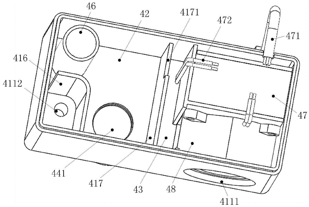
参照图2至图4,雾化发生器4包括外壳41和能够使雾化腔42内的液体雾化为蒸汽的雾化模组44。外壳41内设置有隔板417,隔板417将外壳41分隔成彼此连通的雾化腔42和安装腔43,雾化腔42能够容纳液体,外壳41上设置有与雾化腔42连通的进风口4111、进液口4112和出雾口4113,进液口4112与进液管6连接,出雾口4113与出雾管7连接。雾化模组44包括超声波雾化片441,超声波雾化片441能够通过震动对雾化腔42内的液体进行雾化,以及通过震动检测雾化腔42内的液位高度。安装腔43中设置有控制器47,控制器47通过线缆471与控制单元9连接,通过控制线472与雾化模组44连接,以控制超声波雾化片441的启停。2 to 4 , the atomization generator 4 includes a
通过上述设置方式,本发明大大简化了雾化发生器4的结构,提高了液位测量的精度与准度。具体而言,通过使用超声波雾化片441作为雾化元器件,使得超声波雾化片441集液位测量与雾化功能为一体,既可以通过震动测量雾化腔42的液位高度,又可以对雾化腔42内的液体进行雾化,大大简化了雾化发生器4的结构。并且由于超声波雾化片441的测量原理决定了其在测量时受液位密度、粘度、温度等影响小,因此这种测量方式能够保证测量的精准度。进一步地,通过在外壳41中设置隔板417将外壳41分隔成为雾化腔42和安装腔43,并且在安装腔43中设置与超声波雾化片441连接的控制器47,本发明的雾化发生器4在出厂时就已经将控制器47与超声波雾化片441组装好,从而在滚筒洗衣机组装时,只需将雾化发生器4安装到滚筒洗衣机内部设定位置并将控制器47与控制单元9使用线缆471插接即可,组装过程极为方便,大大简化了组装流程,提高了组装效率。Through the above arrangement, the present invention greatly simplifies the structure of the atomization generator 4 and improves the precision and accuracy of liquid level measurement. Specifically, by using the
下面参照图2至图9,对雾化发生器4进行详细描述。其中,图5为图2在B-B处的剖视图;图6为本发明的雾化发生器去除第二壳盖后的结构图;图7为图2在A-A处的剖视图;图8为本发明的雾化发生器的第一壳盖的结构图(一);图9为本发明的雾化发生器的第一壳盖的结构图(二)。The atomizer generator 4 will be described in detail below with reference to FIGS. 2 to 9 . Wherein, Fig. 5 is a sectional view of Fig. 2 at B-B; Fig. 6 is a structural diagram of the atomizer generator of the present invention after removing the second cover; Fig. 7 is a sectional view of Fig. 2 at A-A; Structural diagram (1) of the first shell cover of the atomization generator; Figure 9 is a structural diagram (2) of the first shell cover of the atomization generator of the present invention.
如图2至图4所示,在一种可能的实施方式中,外壳41包括壳体411、第一壳盖412和第二壳盖413,壳体411内设置有隔板417,隔板417将壳体411分隔成彼此连通的雾化腔42和安装腔43,壳体411底面对应雾化腔42的一侧设置有进液口4112和出雾口4113,壳体411侧面对应安装腔43的位置设置有进风口4111。雾化腔42底面向上延伸有稳流板416,稳流板416设置于进液口4112与超声波雾化片441之间,其一侧与雾化腔42的一内壁固定连接,另一侧延伸至雾化腔42的另一内壁并与该内壁之间形成间隙以便液体流出。参照图5,雾化腔42底部设置有透水孔(图中未示出),超声波雾化片441设置于壳体411外部并通过雾化片支架442内的密封件443密封地连接于该透水孔处,用以将雾化腔42中的液体雾化为水雾。返回参照图4,安装腔43内正对进风口4111的位置设置有控制器47,隔板417具有豁口4171,豁口4171对应控制器47设置于隔板417的一侧。进风口4111与控制器47之间设置有风机48,风机48的吸风口与进风口4111对应设置,出风口朝向隔板417设置,从而风机48在运转时将壳体411外的空气引入壳体411并流经控制器47后绝大部分空气通过豁口4171到达雾化腔42。As shown in FIGS. 2 to 4 , in a possible implementation manner, the
参照图6至图9,外壳41内还形成有与雾化腔42彼此独立的连通腔(图中未示出),雾化腔42通过第一连通孔4141与连通腔连通,出雾口4113通过连接管46和第二连通孔4142与连通腔连通,从而进入雾化腔42的空气带动超声波雾化片441雾化的蒸汽依次经过第一连通孔4141、连通腔、第二连通孔4142和连通管后,从出雾口4113排出。也就是说,进风口4111与出雾口4113之间通过安装腔43、豁口4171、雾化腔42、第一连通孔4141、连通腔、第二连通孔4142和连通管形成了一条完整的气流通道,并且该气流通道流经部分控制器47。返回参照图4和图5,雾化片支架442内还安装有用于驱动超声波雾化片441的驱动电路板444,控制器47分别与驱动电路板444和风机48连接,用以分别控制超声波雾化片441和风机48的启停。其中,安装腔43的底面设置有允许控制线472穿过的穿线孔(图中未示出),控制线472的一端与驱动电路板444连接,另一端穿过穿线孔与控制器47连接。Referring to FIGS. 6 to 9 , a communication cavity (not shown in the figure) that is independent of the
参照图8和图9,在一种可能的实施方式中,第一壳盖412上设置有横向筋板414和竖向筋板415,横向筋板414与第一壳盖412的三个依次相邻的内侧面固定连接,竖向筋板415与第一壳盖412的顶面以及上述三个依次相邻的内侧面中两个相对的内侧面固定连接,从而横向筋板414、竖向筋板415以及三个依次相邻的内侧面共同围设形成上述的连通腔,第二壳盖413能够盖设在连通腔上。参照图4、图7和图8,横向筋板414上对应雾化腔42和出雾口4113开设有第一连通孔4141和第二连通孔4142,雾化腔42通过第一连通孔4141与连通腔连接,出雾口4113通过连接管46与第二连通孔4142连接。横向筋板414的底面向下还延伸有挡风板4143,挡风板4143延伸至雾化腔42内并对应于豁口4171设置。Referring to FIGS. 8 and 9 , in a possible implementation manner, the
参照图6和图7,在一种可能的实施方式中,连通腔内还设置有阀机构45,阀机构45设置成能够同时密封第一连通孔4141和第二连通孔4142。其中,阀机构45包括驱动部451和密封块452,控制器47与驱动部451连接,用于控制驱动部451的启停,驱动部451与密封块452连接,并能够在控制器47的控制下驱动密封块452在连通腔内往复滑动。如驱动部451为气缸、电缸或直线电机,驱动部451的输出轴与密封块452固定连接,从而驱动密封块452在连通腔中滑动。密封块452的底面能够同时覆盖第一连通孔4141和第二连通孔4142,并且覆盖后保持相对较好的密封。6 and 7 , in a possible implementation manner, a
上述设置方式的优点在于:通过使用超声波雾化片441作为雾化元件,能够利用超声波雾化片441的原理实现检测液位功能与雾化功能的集成,大大简化雾化发生器4的结构,并且超声波雾化片441的测量原理决定了其在测量时受液体密度、粘度和温度等影响小,因此其能够保证液位的测量精度。雾化腔42内对应进液口4112处设置有稳流板416,稳流板416将进液口4112与超声波雾化片441隔离开的设置方式,还使得雾化腔42在进液时,稳流板416能够有效抑制液体进入雾化腔42时产生的水花,减小水流冲击等带来的液位波动,进一步提高超声波雾化片441的液位检测精度。通过使用隔板417将壳体411分隔为雾化腔42和安装腔43,并在安装腔43内设置控制器47分别与驱动电路板444、驱动部451和风机48连接,使得本发明的雾化发生器4实现了高度集成化,控制器47能够同时控制超声波雾化片441、驱动部451和风机48的启停,避免了在组装洗衣机时对上述元器件分别接线,提高了组装效率。在控制器47与进风口4111之间设置风机48,并且风机48的吸风口与进风口4111对应设置、出风口朝向隔板417设置,隔板417对应于控制器47的位置设置豁口4171,还能够在雾化发生器4工作时,利用雾化发生器4工作时的气流流经控制器47为控制器47进行散热,从而提高控制器47的工作寿命和工作稳定性。The advantage of the above arrangement is that: by using the
通过将连通腔设置于第一盖体上,而将出雾口4113设置于壳体411底面,进而将出雾口4113与第二连通孔4142使用连通管连接,使得安装腔43、雾化腔42、连通腔与连通管之间形成一条完整的气流通道,在加上风机48的作用,使得水雾的排出自然强劲。出雾口4113设置在外壳41底面则方便与出雾管7的连接,使出雾管7无需弯折便可与外筒3连接,缩短了水雾的喷射行程,提高了水雾的喷射效果。横向筋板414的底面对应豁口4171延伸挡风板4143的设置方式,使得风机48吹出的风在经过豁口4171后绕行,从而提高风对水雾的携带效果,达到水雾快速排出的目的,避免风吹出而水雾残留在雾化腔42的情况出现。将超声波雾化片441通过雾化片支架442密封地设置于壳体411外部,以及将穿线孔设置在安装腔43中,使得控制线472的走线不经过雾化腔42,避免了控制线472与水接触而导致的安全问题的出现,提高了雾化发生器4的安全性。By arranging the communication cavity on the first cover body, the
雾化元件采用超声波雾化片441,雾化发生器4利用电子高频震荡(振荡频率为1.7MHz或2.4MHz等超过听觉范围的频率,该电子振荡对人体及动物绝无伤害),通过雾化片的高频谐振,将液态水分子结构打散而产生自然飘逸的水雾,水雾化为1至100微米的超微粒子,均匀,不需加热或添加任何化学试剂。与加热雾化方式比较,能源节省了90%。另外在雾化过程中将释放大量的负离子,其与空气中漂浮的烟雾、粉尘等产生静电式反应,使其沉淀,同时还能有效去除甲醛、一氧化碳、细菌等有害物质,微米级的水分子可以更快的吸附在衣物上,使得衣物护理体验更佳。The atomizing element adopts the
通过在雾化发生器4内设置连通腔以及在连通腔内设置阀机构45,能够大大提升洗衣机的运行安全性,有效避免烘干模块5启动时湿热空气逆流至雾化发生器4和洗衣机内部而导致的和电气元件受潮短路的情况出现。具体而言,通过在外壳41中设置与雾化腔42彼此独立的连通腔,并且雾化腔42与出雾口4113通过连通腔连通,使得连通腔成为了水雾从雾化腔42到达出雾口4113的必经通道。而连通腔内设置有阀机构45,阀机构45能够密封第一连通孔4141和第二连通孔4142的设置方式,则使得阀机构45能够将该通道完全截断,从而阻止外界空气流从出雾口4113逆流至雾化发生器4内,尤其是在洗衣机的烘干模块5启动时,能够阻断洗涤桶内的潮湿空气逆流至雾化发生器4进而从进风口4111排出至洗衣机内部,避免了雾化发生器4和洗衣机内的电气元件受潮短路等故障的情况出现,极大地提高了洗衣机的运行安全性。并且,上述设置方式可行性高,效果突出,有利于大规模推广使用。By arranging a communication cavity in the atomization generator 4 and a
需要说明的是,上述优选的实施方式仅仅用于阐述本发明的原理,并非旨在于限制本发明的保护范围。在不偏离本发明原理的前提下,本领域技术人员可以对上述设置方式进行调整,以便本发明能够适用于更加具体的应用场景。It should be noted that the above preferred embodiments are only used to illustrate the principle of the present invention, and are not intended to limit the protection scope of the present invention. On the premise of not departing from the principles of the present invention, those skilled in the art can adjust the above setting manners, so that the present invention can be applied to more specific application scenarios.
例如,在一种可替换的实施方式中,阀机构45的设置形式并非一成不变,本领域技术人员可以对其进行调整,只要其满足能够密封第一连通孔4141和/或第二连通孔4142的条件即可。例如,还可以选取普通电机作为驱动部451,而在驱动部451与密封块452之间添加传动构件完成密封块452的往复滑动。如传动构件可以为滚珠丝杠等。再如,密封块452还可以设置成只密封第一连通孔4141和第二连通孔4142中的一个,同样可以实现防止湿热空气反流的功能。For example, in an alternative embodiment, the setting form of the
再如,在另一种可替换的实施方式中,壳体411上还可以不设置风机48,而是将风机48设置在壳体411内或其他位置,只要该设置位置能够使水雾有效地从雾化腔42中排出即可。如,风机48还可以设置在出雾管7上等。For another example, in another alternative embodiment, the
再如,在另一种可替换的实施方式中,本领域技术人员也可以对连通腔的设置位置进行调整,只要连通腔的设置方式能够满足于雾化腔42彼此独立的条件即可。例如,连通腔还可以设置在壳体411内部,而非第一壳盖412上。For another example, in another alternative embodiment, those skilled in the art can also adjust the arrangement position of the communication cavity, as long as the arrangement of the communication cavity can satisfy the condition that the
再如,在另一种可替换的实施方式中,出雾口4113的设置位置并非唯一,其还可以设置在壳体411的侧壁上、第一壳盖412上或第二壳盖413上等,相应地只需调整第二连通孔4142和连接管46的设置位置即可。这种出雾口4113的设置位置的调整并未偏离本发明的原理。For another example, in another alternative embodiment, the setting position of the
再如,在另一种可替换的实施方式中,稳流板416的设置形式和设置位置可以进行调整,只要该调整满足在雾化腔42进液时能够减小液面波动的条件即可。例如,稳流板416还可以设置在雾化腔42的内壁上或第一盖体上,并且其下侧与雾化腔42之间留有一定的间隙。For another example, in another alternative embodiment, the setting form and setting position of the
当然,上述可以替换的实施方式之间、以及可以替换的实施方式和优选的实施方式之间还可以交叉配合使用,从而组合出新的实施方式以适用于更加具体的应用场景。Of course, the above-mentioned alternative embodiments, as well as between the alternative embodiments and the preferred embodiments, can also be used in cross-combination, so that new embodiments can be combined to be suitable for more specific application scenarios.
下面参照图10,对本发明的滚筒洗衣机的控制方法进行描述,其中,图10为本发明的滚筒洗衣机的控制方法的流程图。The control method of the drum washing machine of the present invention will be described below with reference to FIG. 10 , wherein FIG. 10 is a flowchart of the control method of the drum washing machine of the present invention.
如图10所示,本发明的滚筒洗衣机的控制方法主要包括:As shown in Figure 10, the control method of the drum washing machine of the present invention mainly includes:
S100、控制电磁阀8开启,如在用户选择滚筒洗衣机的蒸汽洗等相关功能后,控制单元9控制电磁阀8开启以向雾化腔42内进水;S100, control the solenoid valve 8 to open, for example, after the user selects related functions such as steam washing of the drum washing machine, the control unit 9 controls the solenoid valve 8 to open to feed water into the
S200、在电磁阀8开启的同时,控制超声波雾化片441震动以检测雾化腔42内液位的高度,如在电磁阀8开启的同时,控制器47控制驱动电路板444接通,驱动电路板444驱动超声波雾化片441工作,超声波雾化片441通过震动检测雾化腔42内液位的高度;当然,超声波雾化片441检测的时机可以进行调整,如在电磁阀8开启一定时间后控制超声波雾化片441震动以检测雾化腔42内液位的高度。S200. When the solenoid valve 8 is turned on, the
S300、判断液位的高度是否达到设定高度,如设定高度为基于衣物重量计算出来的高度或预先设定好的高度,在超声波雾化片441检测液位的高度的同时,判断该液位的高度是否达到设定高度;S300, judging whether the height of the liquid level reaches the set height, if the set height is the height calculated based on the weight of the clothes or a preset height, when the
S400、基于判断结果,选择性地控制电磁阀8关闭;如在液位高度达到设定高度时,控制电磁阀8关闭,在液位高度未达到设定高度时,超声波雾化片441持续检测液位的高度。S400, based on the judgment result, selectively control the solenoid valve 8 to close; for example, when the liquid level reaches the set height, control the solenoid valve 8 to close, and when the liquid level does not reach the set height, the
通过上述控制方法,本发明的滚筒洗衣机能够利用超声波雾化片441检测液位的高度,提高液位的测量精准度,从而提高滚筒洗衣机的控制精度。Through the above control method, the drum washing machine of the present invention can use the
下面参照图1至图10,对一种可能的实施方式中,滚筒洗衣机的工作过程进行描述。1 to 10 , in a possible implementation manner, the working process of the front-loading washing machine will be described.
在一种可能的实施方式中,用户在滚筒洗衣机的控制面板上选择了蒸汽洗选项后,电磁阀8开启,雾化腔42内进水,超声波雾化片441先检测液位的高度,待液位到达设定高度后,电磁阀8关闭,控制器47控制驱动电路板444和风机48同时启动,超声波雾化片441对雾化腔42内的水进行雾化,同时风机48将外部空气通过进风口4111引入安装腔43,空气流经控制器47对控制器47进行降温后,通过豁口4171流入雾化腔42,并带动超声波雾化片雾化的蒸汽依次经过第一连通孔4141、连通腔、第二连通孔4142、连通管、出雾口4113和出雾管7后,喷射至内筒2中对衣物进行处理。In a possible implementation, after the user selects the steam washing option on the control panel of the drum washing machine, the solenoid valve 8 is turned on, water enters the
至此,已经结合附图所示的优选实施方式描述了本发明的技术方案,但是,本领域技术人员容易理解的是,本发明的保护范围显然不局限于这些具体实施方式。在不偏离本发明的原理的前提下,本领域技术人员可以对相关技术特征作出等同的更改或替换,这些更改或替换之后的技术方案都将落入本发明的保护范围之内。So far, the technical solutions of the present invention have been described with reference to the preferred embodiments shown in the accompanying drawings, however, those skilled in the art can easily understand that the protection scope of the present invention is obviously not limited to these specific embodiments. Without departing from the principle of the present invention, those skilled in the art can make equivalent changes or substitutions to the relevant technical features, and the technical solutions after these changes or substitutions will fall within the protection scope of the present invention.
Claims (10)
Priority Applications (5)
| Application Number | Priority Date | Filing Date | Title |
|---|---|---|---|
| CN201910165011.8A CN111663286B (en) | 2019-03-05 | 2019-03-05 | Atomizer generator, laundry treatment equipment and control method thereof |
| EP20766633.0A EP3936652B1 (en) | 2019-03-05 | 2020-03-02 | Atomising generator, clothing treatment device, and control method therefor |
| US17/436,257 US12043946B2 (en) | 2019-03-05 | 2020-03-02 | Atomising generator, clothing treatment device, and control method therefor |
| JP2021551850A JP7228710B2 (en) | 2019-03-05 | 2020-03-02 | Atomization generator, clothing processing equipment and control method thereof |
| PCT/CN2020/077457 WO2020177671A1 (en) | 2019-03-05 | 2020-03-02 | Atomising generator, clothing treatment device, and control method therefor |
Applications Claiming Priority (1)
| Application Number | Priority Date | Filing Date | Title |
|---|---|---|---|
| CN201910165011.8A CN111663286B (en) | 2019-03-05 | 2019-03-05 | Atomizer generator, laundry treatment equipment and control method thereof |
Publications (2)
| Publication Number | Publication Date |
|---|---|
| CN111663286A true CN111663286A (en) | 2020-09-15 |
| CN111663286B CN111663286B (en) | 2023-12-05 |
Family
ID=72337644
Family Applications (1)
| Application Number | Title | Priority Date | Filing Date |
|---|---|---|---|
| CN201910165011.8A Active CN111663286B (en) | 2019-03-05 | 2019-03-05 | Atomizer generator, laundry treatment equipment and control method thereof |
Country Status (5)
| Country | Link |
|---|---|
| US (1) | US12043946B2 (en) |
| EP (1) | EP3936652B1 (en) |
| JP (1) | JP7228710B2 (en) |
| CN (1) | CN111663286B (en) |
| WO (1) | WO2020177671A1 (en) |
Cited By (1)
| Publication number | Priority date | Publication date | Assignee | Title |
|---|---|---|---|---|
| CN114808305A (en) * | 2022-05-17 | 2022-07-29 | 北京奥润联创微电子科技开发有限公司 | Ultrasonic atomizing coating head |
Families Citing this family (1)
| Publication number | Priority date | Publication date | Assignee | Title |
|---|---|---|---|---|
| US11585030B1 (en) * | 2021-12-11 | 2023-02-21 | Eve Street Designs Pty Ltd. | Portable plunger-wash bag apparatus and method of use to clean laundry |
Citations (11)
| Publication number | Priority date | Publication date | Assignee | Title |
|---|---|---|---|---|
| CN1958926A (en) * | 2006-06-06 | 2007-05-09 | 南京乐金熊猫电器有限公司 | Vapor generation set of drum-type washing machine |
| CN201212831Y (en) * | 2008-06-18 | 2009-03-25 | 山东电力中心医院 | Atomizing tank liquid level measurement and display device for medical ultrasonic atomizer |
| CN202539014U (en) * | 2012-03-19 | 2012-11-21 | 宋志辉 | Ultrasonic nebulizer |
| CN203683967U (en) * | 2014-01-20 | 2014-07-02 | 徐万群 | Steam and dry iron with ironing bottom plate capable of conveniently stretching out and drawing back |
| CN104374032A (en) * | 2014-09-30 | 2015-02-25 | 潘浩斌 | Novel ultrasonic humidifier |
| JP2016016230A (en) * | 2014-07-10 | 2016-02-01 | パナソニックIpマネジメント株式会社 | Cloth processing equipment |
| CN205262547U (en) * | 2015-12-31 | 2016-05-25 | 深圳飞安瑞电子科技有限公司 | A lack of water detection circuitry for ultrasonic atomization ware |
| CN106403145A (en) * | 2015-08-13 | 2017-02-15 | 陈楚娇 | Ultrasonic humidifier |
| CN108645485A (en) * | 2018-05-30 | 2018-10-12 | 广东奥迪威传感科技股份有限公司 | A kind of level testing methods and device for atomizer |
| CN208536233U (en) * | 2018-05-30 | 2019-02-22 | 广东奥迪威传感科技股份有限公司 | an atomizer |
| CN210117537U (en) * | 2019-03-05 | 2020-02-28 | 青岛海尔洗衣机有限公司 | Atomizer, Clothes Treatment Equipment |
Family Cites Families (16)
| Publication number | Priority date | Publication date | Assignee | Title |
|---|---|---|---|---|
| FR2746656B1 (en) * | 1996-03-26 | 1999-05-28 | System Assistance Medical | PRESSURE SENSOR NEBULIZER |
| US6543701B1 (en) * | 2001-12-21 | 2003-04-08 | Tung-Huang Ho | Pocket-type ultrasonic atomizer structure |
| US20060188646A1 (en) * | 2005-02-21 | 2006-08-24 | Yun Ju Y | System and method for detecting remaining amount of precursor in vessel during CVD process |
| EP1888257A1 (en) * | 2005-05-05 | 2008-02-20 | Pulmatrix, Inc. | Ultrasonic aerosol generator |
| CN2884012Y (en) * | 2006-02-08 | 2007-03-28 | 北京亚都科技股份有限公司 | Ultrasonic mist humidifier |
| JP2009072653A (en) * | 2007-09-19 | 2009-04-09 | Panasonic Corp | Ultrasonic atomizer |
| JP4935744B2 (en) * | 2008-04-10 | 2012-05-23 | パナソニック株式会社 | Washing machine |
| CN101660158A (en) * | 2008-08-27 | 2010-03-03 | 鸿富锦精密工业(深圳)有限公司 | Film preparation device |
| CN101949578B (en) * | 2010-10-27 | 2012-07-18 | 法雷奥汽车空调湖北有限公司 | Automobile air-conditioner condensed water cold energy recycling device |
| DE102012213934A1 (en) * | 2012-08-07 | 2014-02-13 | BSH Bosch und Siemens Hausgeräte GmbH | Washing machine with apparatus for producing water droplets and method for its operation |
| KR102227372B1 (en) * | 2014-04-21 | 2021-03-11 | 엘지전자 주식회사 | Laundry washing method |
| FR3050146B1 (en) * | 2016-04-18 | 2019-04-19 | Valeo Systemes Thermiques | AIR REFRESHING DEVICE FOR VEHICLE AND HEATING, VENTILATION AND / OR AIR CONDITIONING SYSTEM THEREOF |
| CN109688887A (en) * | 2016-09-16 | 2019-04-26 | Bsh家用电器有限公司 | Household appliance with aerosol generator and method of operation |
| CN106524373B (en) | 2016-11-16 | 2022-04-01 | 广州奥迪威传感应用科技有限公司 | Humidifying method, humidifying device and aromatherapy machine |
| CN206786891U (en) * | 2017-06-08 | 2017-12-22 | 郑宗彪 | A kind of ceiling mounting type ultrasonic purification device |
| CN107700143A (en) * | 2017-11-10 | 2018-02-16 | 浙江大学 | Pinpoint ultrasonic microbubble joint clothes washer-dryer and its method |
-
2019
- 2019-03-05 CN CN201910165011.8A patent/CN111663286B/en active Active
-
2020
- 2020-03-02 EP EP20766633.0A patent/EP3936652B1/en active Active
- 2020-03-02 US US17/436,257 patent/US12043946B2/en active Active
- 2020-03-02 WO PCT/CN2020/077457 patent/WO2020177671A1/en not_active Ceased
- 2020-03-02 JP JP2021551850A patent/JP7228710B2/en active Active
Patent Citations (11)
| Publication number | Priority date | Publication date | Assignee | Title |
|---|---|---|---|---|
| CN1958926A (en) * | 2006-06-06 | 2007-05-09 | 南京乐金熊猫电器有限公司 | Vapor generation set of drum-type washing machine |
| CN201212831Y (en) * | 2008-06-18 | 2009-03-25 | 山东电力中心医院 | Atomizing tank liquid level measurement and display device for medical ultrasonic atomizer |
| CN202539014U (en) * | 2012-03-19 | 2012-11-21 | 宋志辉 | Ultrasonic nebulizer |
| CN203683967U (en) * | 2014-01-20 | 2014-07-02 | 徐万群 | Steam and dry iron with ironing bottom plate capable of conveniently stretching out and drawing back |
| JP2016016230A (en) * | 2014-07-10 | 2016-02-01 | パナソニックIpマネジメント株式会社 | Cloth processing equipment |
| CN104374032A (en) * | 2014-09-30 | 2015-02-25 | 潘浩斌 | Novel ultrasonic humidifier |
| CN106403145A (en) * | 2015-08-13 | 2017-02-15 | 陈楚娇 | Ultrasonic humidifier |
| CN205262547U (en) * | 2015-12-31 | 2016-05-25 | 深圳飞安瑞电子科技有限公司 | A lack of water detection circuitry for ultrasonic atomization ware |
| CN108645485A (en) * | 2018-05-30 | 2018-10-12 | 广东奥迪威传感科技股份有限公司 | A kind of level testing methods and device for atomizer |
| CN208536233U (en) * | 2018-05-30 | 2019-02-22 | 广东奥迪威传感科技股份有限公司 | an atomizer |
| CN210117537U (en) * | 2019-03-05 | 2020-02-28 | 青岛海尔洗衣机有限公司 | Atomizer, Clothes Treatment Equipment |
Cited By (2)
| Publication number | Priority date | Publication date | Assignee | Title |
|---|---|---|---|---|
| CN114808305A (en) * | 2022-05-17 | 2022-07-29 | 北京奥润联创微电子科技开发有限公司 | Ultrasonic atomizing coating head |
| CN114808305B (en) * | 2022-05-17 | 2024-05-17 | 北京奥润联创微电子科技开发有限公司 | Ultrasonic atomizing coating head |
Also Published As
| Publication number | Publication date |
|---|---|
| WO2020177671A1 (en) | 2020-09-10 |
| US20220154384A1 (en) | 2022-05-19 |
| EP3936652B1 (en) | 2023-12-20 |
| CN111663286B (en) | 2023-12-05 |
| US12043946B2 (en) | 2024-07-23 |
| EP3936652A1 (en) | 2022-01-12 |
| EP3936652A4 (en) | 2022-05-18 |
| JP2022522500A (en) | 2022-04-19 |
| JP7228710B2 (en) | 2023-02-24 |
Similar Documents
| Publication | Publication Date | Title |
|---|---|---|
| CN111472141A (en) | Atomization generator and clothes treatment equipment comprising same | |
| CN210117537U (en) | Atomizer, Clothes Treatment Equipment | |
| US11807977B2 (en) | Atomizing generator and clothes treatment apparatus comprising the atomizing generator | |
| CN111663302B (en) | Atomization device for clothing treatment equipment, clothing treatment equipment and control method | |
| CN107780134B (en) | Washing machine with steam washing nursing function | |
| CN111663281A (en) | Atomization generator, clothes treatment equipment and control method thereof | |
| TWI422722B (en) | Laundry dryer | |
| CN111663286A (en) | Atomization generator, clothes treatment equipment and control method thereof | |
| CN210117533U (en) | Atomizer, Clothes Treatment Equipment | |
| CN210117540U (en) | Pulsator washing machine | |
| CN210177181U (en) | Atomization device for clothes treatment equipment and clothes treatment equipment | |
| JP4809065B2 (en) | Bathroom heating device and bathroom system with mist generation function | |
| JP7133653B2 (en) | clothing processing equipment | |
| CN111663288A (en) | pulsator washing machine | |
| CN110057012A (en) | A kind of ultrasonic humidifier and its control method | |
| CN110732447B (en) | Atomizing device and washing machine | |
| CN108421656A (en) | A nano-fog generating device | |
| CN218961399U (en) | Aromatherapy instrument | |
| CN216786563U (en) | Champignon device and clothing care apparatus | |
| CN218033500U (en) | Humidifier | |
| CN220771283U (en) | Fog-free humidifier | |
| CN219049680U (en) | Aromatherapy machine with upper cover convenient to open | |
| KR200284594Y1 (en) | humid fire | |
| WO2020125590A1 (en) | Control method for laundry treatment device and laundry treatment device | |
| CN120859382A (en) | Spraying device and dish washer |
Legal Events
| Date | Code | Title | Description |
|---|---|---|---|
| PB01 | Publication | ||
| PB01 | Publication | ||
| SE01 | Entry into force of request for substantive examination | ||
| SE01 | Entry into force of request for substantive examination | ||
| CB02 | Change of applicant information | ||
| CB02 | Change of applicant information |
Address after: 266101 Haier Industrial Park, 1 Haier Road, Laoshan District, Shandong, Qingdao Applicant after: QINGDAO HAIER WASHING MACHINE Co.,Ltd. Applicant after: Haier Smart Home Co., Ltd. Address before: 266101 Haier Industrial Park, 1 Haier Road, Laoshan District, Shandong, Qingdao Applicant before: QINGDAO HAIER WASHING MACHINE Co.,Ltd. Applicant before: QINGDAO HAIER JOINT STOCK Co.,Ltd. |
|
| TA01 | Transfer of patent application right | ||
| TA01 | Transfer of patent application right |
Effective date of registration: 20231109 Address after: 201600 t-14, 1f, No. 18, Lane 945, changta Road, Shihudang Town, Songjiang District, Shanghai Applicant after: Shanghai Haier washing Electric Appliance Co.,Ltd. Applicant after: Haier Smart Home Co., Ltd. Address before: 266101 Haier Industrial Park, 1 Haier Road, Laoshan District, Shandong, Qingdao Applicant before: QINGDAO HAIER WASHING MACHINE Co.,Ltd. Applicant before: Haier Smart Home Co., Ltd. |
|
| GR01 | Patent grant | ||
| GR01 | Patent grant | ||
| CP03 | Change of name, title or address | ||
| CP03 | Change of name, title or address |
Address after: 201617 Shanghai Shanghong District Shihudang Town Shuangjin Road 751 Lane 1, 2, 3 Number Patentee after: Shanghai Haier washing Electric Appliance Co.,Ltd. Country or region after: China Patentee after: Haier Smart Home Co., Ltd. Address before: 201600 t-14, 1f, No. 18, Lane 945, changta Road, Shihudang Town, Songjiang District, Shanghai Patentee before: Shanghai Haier washing Electric Appliance Co.,Ltd. Country or region before: China Patentee before: Haier Smart Home Co., Ltd. |