EP3936445A1 - Ultrasound sensor - Google Patents
Ultrasound sensor Download PDFInfo
- Publication number
- EP3936445A1 EP3936445A1 EP20185306.6A EP20185306A EP3936445A1 EP 3936445 A1 EP3936445 A1 EP 3936445A1 EP 20185306 A EP20185306 A EP 20185306A EP 3936445 A1 EP3936445 A1 EP 3936445A1
- Authority
- EP
- European Patent Office
- Prior art keywords
- ultrasonic
- ultrasonic sensor
- receiver
- transmitter
- weakening
- Prior art date
- Legal status (The legal status is an assumption and is not a legal conclusion. Google has not performed a legal analysis and makes no representation as to the accuracy of the status listed.)
- Pending
Links
- 238000002604 ultrasonography Methods 0.000 title abstract 4
- 239000000463 material Substances 0.000 claims abstract description 63
- 238000012544 monitoring process Methods 0.000 claims abstract description 14
- 230000003313 weakening effect Effects 0.000 claims description 24
- 239000006096 absorbing agent Substances 0.000 claims description 22
- 230000002745 absorbent Effects 0.000 claims description 15
- 239000002250 absorbent Substances 0.000 claims description 15
- 239000011148 porous material Substances 0.000 claims description 15
- 230000005540 biological transmission Effects 0.000 claims description 6
- 239000002184 metal Substances 0.000 claims description 6
- 230000000737 periodic effect Effects 0.000 claims description 5
- 239000011888 foil Substances 0.000 claims description 3
- 238000007373 indentation Methods 0.000 claims description 3
- 230000002209 hydrophobic effect Effects 0.000 claims description 2
- 238000001514 detection method Methods 0.000 description 7
- 239000012876 carrier material Substances 0.000 description 4
- 238000011156 evaluation Methods 0.000 description 3
- 238000000034 method Methods 0.000 description 3
- 238000010521 absorption reaction Methods 0.000 description 2
- 238000004026 adhesive bonding Methods 0.000 description 1
- 238000004140 cleaning Methods 0.000 description 1
- 230000001419 dependent effect Effects 0.000 description 1
- 238000013461 design Methods 0.000 description 1
- 238000011161 development Methods 0.000 description 1
- 230000018109 developmental process Effects 0.000 description 1
- 230000000694 effects Effects 0.000 description 1
- 238000004049 embossing Methods 0.000 description 1
- 238000005530 etching Methods 0.000 description 1
- 238000005187 foaming Methods 0.000 description 1
- 238000001746 injection moulding Methods 0.000 description 1
- 230000010354 integration Effects 0.000 description 1
- 238000003754 machining Methods 0.000 description 1
- 238000004519 manufacturing process Methods 0.000 description 1
- 239000011159 matrix material Substances 0.000 description 1
- 239000002245 particle Substances 0.000 description 1
- 230000000149 penetrating effect Effects 0.000 description 1
- 238000003825 pressing Methods 0.000 description 1
- 238000012545 processing Methods 0.000 description 1
- 239000002994 raw material Substances 0.000 description 1
- 238000005245 sintering Methods 0.000 description 1
- XLYOFNOQVPJJNP-UHFFFAOYSA-N water Substances O XLYOFNOQVPJJNP-UHFFFAOYSA-N 0.000 description 1
Images


Classifications
-
- G—PHYSICS
- G01—MEASURING; TESTING
- G01S—RADIO DIRECTION-FINDING; RADIO NAVIGATION; DETERMINING DISTANCE OR VELOCITY BY USE OF RADIO WAVES; LOCATING OR PRESENCE-DETECTING BY USE OF THE REFLECTION OR RERADIATION OF RADIO WAVES; ANALOGOUS ARRANGEMENTS USING OTHER WAVES
- G01S15/00—Systems using the reflection or reradiation of acoustic waves, e.g. sonar systems
- G01S15/02—Systems using the reflection or reradiation of acoustic waves, e.g. sonar systems using reflection of acoustic waves
- G01S15/04—Systems determining presence of a target
-
- G—PHYSICS
- G01—MEASURING; TESTING
- G01S—RADIO DIRECTION-FINDING; RADIO NAVIGATION; DETERMINING DISTANCE OR VELOCITY BY USE OF RADIO WAVES; LOCATING OR PRESENCE-DETECTING BY USE OF THE REFLECTION OR RERADIATION OF RADIO WAVES; ANALOGOUS ARRANGEMENTS USING OTHER WAVES
- G01S7/00—Details of systems according to groups G01S13/00, G01S15/00, G01S17/00
- G01S7/52—Details of systems according to groups G01S13/00, G01S15/00, G01S17/00 of systems according to group G01S15/00
- G01S7/521—Constructional features
-
- G—PHYSICS
- G10—MUSICAL INSTRUMENTS; ACOUSTICS
- G10K—SOUND-PRODUCING DEVICES; METHODS OR DEVICES FOR PROTECTING AGAINST, OR FOR DAMPING, NOISE OR OTHER ACOUSTIC WAVES IN GENERAL; ACOUSTICS NOT OTHERWISE PROVIDED FOR
- G10K11/00—Methods or devices for transmitting, conducting or directing sound in general; Methods or devices for protecting against, or for damping, noise or other acoustic waves in general
- G10K11/002—Devices for damping, suppressing, obstructing or conducting sound in acoustic devices
-
- G—PHYSICS
- G10—MUSICAL INSTRUMENTS; ACOUSTICS
- G10K—SOUND-PRODUCING DEVICES; METHODS OR DEVICES FOR PROTECTING AGAINST, OR FOR DAMPING, NOISE OR OTHER ACOUSTIC WAVES IN GENERAL; ACOUSTICS NOT OTHERWISE PROVIDED FOR
- G10K11/00—Methods or devices for transmitting, conducting or directing sound in general; Methods or devices for protecting against, or for damping, noise or other acoustic waves in general
- G10K11/16—Methods or devices for protecting against, or for damping, noise or other acoustic waves in general
- G10K11/162—Selection of materials
-
- G—PHYSICS
- G10—MUSICAL INSTRUMENTS; ACOUSTICS
- G10K—SOUND-PRODUCING DEVICES; METHODS OR DEVICES FOR PROTECTING AGAINST, OR FOR DAMPING, NOISE OR OTHER ACOUSTIC WAVES IN GENERAL; ACOUSTICS NOT OTHERWISE PROVIDED FOR
- G10K11/00—Methods or devices for transmitting, conducting or directing sound in general; Methods or devices for protecting against, or for damping, noise or other acoustic waves in general
- G10K11/16—Methods or devices for protecting against, or for damping, noise or other acoustic waves in general
- G10K11/172—Methods or devices for protecting against, or for damping, noise or other acoustic waves in general using resonance effects
Definitions
- the invention relates to an ultrasonic sensor.
- Such ultrasonic sensors are generally used to detect objects in a monitoring area and for this purpose have an ultrasonic transmitter that emits ultrasonic waves and an ultrasonic receiver that receives ultrasonic waves.
- An application example for such an ultrasonic sensor is the detection of labels on a carrier material.
- the ultrasonic transmitter and the ultrasonic receiver are typically integrated in different fork arms of a fork-shaped housing of the ultrasonic sensor, with the fork arms delimiting the monitoring area on opposite edges.
- the backing material with the labels is then conveyed through the monitoring area.
- ultrasonic waves emitted by the ultrasonic transmitter are guided through a transmission opening in the housing into the monitoring area.
- the ultrasonic waves Depending on whether the ultrasonic waves only hit the carrier material or the carrier material with a label arranged on it, they are weakened to different degrees.
- the ultrasonic waves guided through a receiving opening to the ultrasonic receiver generate different received signals, which are evaluated in an evaluation unit for detecting the labels.
- the ultrasonic receivers are not completely guided through the reception opening, but are partly reflected on the housing.
- the ultrasonic waves can be reflected back and forth between the fork arms several times.
- the ultrasonic waves emitted as the first pulse can sometimes be reflected back and forth several times between the forks of the housing and then overlap with the next pulse. This can lead to interference of the ultrasonic waves, which can result in false detections.
- the object of the invention is to provide an ultrasonic sensor which has high functionality and detection reliability.
- the invention relates to an ultrasonic sensor for detecting objects in a monitoring area, with an ultrasonic transmitter that emits ultrasonic waves and with an ultrasonic receiver that receives ultrasonic waves.
- a receiving opening is provided in a housing accommodating the ultrasonic receiver, through which ultrasonic waves emitted by the transmitter and guided through the monitoring area are guided to the ultrasonic receiver.
- the receiving opening is surrounded by an attenuating material which absorbs or diffusely reflects ultrasonic waves.
- the portion of the ultrasonic waves that are not guided through the receiving opening to the ultrasonic receiver is greatly weakened by the absorbing or diffusely scattering property of the attenuating material, so that this portion of the ultrasonic waves cannot lead to false detections during object detection due to undesired multiple reflections .
- the attenuating materials according to the invention can advantageously be used in different types of ultrasonic sensors to improve detection reliability.
- the ultrasonic sensor can be a button, in which case the ultrasonic transmitter and the ultrasonic sensor are arranged on the same side of the monitoring area.
- the ultrasonic transmitter and the ultrasonic receiver are then preferably arranged in a common housing.
- the attenuating materials are used to avoid multiple reflections between the housing and the background.
- the ultrasonic transmitter and the ultrasonic receiver can be arranged on opposite edges of the monitored area, in which case the ultrasonic sensor works according to the transmission principle.
- objects in the monitored area are recognized by the fact that they weaken or totally reflect the ultrasonic waves, so that compared to a free monitored area, only part of the ultrasonic waves reaches the receiver.
- the ultrasonic transmitter and the ultrasonic receiver can be arranged in separate housings.
- the ultrasonic transmitter and the ultrasonic receiver can be arranged in different fork arms of a fork-shaped housing.
- the attenuating material prevents multiple reflections between the housings or housing parts in which the ultrasonic transmitter and the ultrasonic receiver are integrated.
- the absorbent weakening material is a pore absorber.
- the pore sizes of the attenuating material are adapted to the frequency or the wavelength of the ultrasonic waves, so that an optimal absorption effect is achieved.
- the pore absorber has pore sizes in the area of the viscosity boundary layer.
- the viscosity boundary layer is the layer of air at a distance from a reverberant wall at which the movement of air particles is slowed down by friction on this wall. If the diameter of the pores is in the range of the viscosity boundary layer, absorption by friction takes place in these pores.
- the pore absorber is an open-pored plastic or an open-pored metal.
- the open-pored structure can be obtained, for example, by foaming.
- the absorbent attenuating material may be micro-apertured.
- micro-openings can be produced, for example, by etching or lasering.
- the absorbent weakening material has microfine through-holes, the diameter of which is adapted to the frequency of the ultrasonic waves.
- the absorbent weakening material is in the form of plates or foils.
- the absorbent weakening material is a perforated plate absorber.
- the absorbing attenuation material is designed in the form of Helmholtz resonators.
- the sizes of the hole structures are adapted to the frequency of the ultrasonic waves and are typically in the ⁇ m range.
- the diffusely scattering attenuating material has an arrangement of depressions.
- the indentations are in the range of ⁇ /4 of the wavelength of the ultrasonic waves.
- the ultrasonic waves are diffusely scattered in the depressions.
- the depressions can be formed, for example, in that a flat, plate-shaped body is bent or shaped accordingly, so that in particular a periodic or specific sequence of linear depressions is produced.
- the diffusely scattering attenuating material can have a periodic arrangement of scattering structures.
- the diffusely scattering attenuating material can be plate-shaped, from the upper side of which the scattering structures protrude.
- the scattering structures extend in the longitudinal or transverse direction of the plate-shaped attenuating material.
- the structure period of the scattering structures is in the range of the wavelength of the ultrasonic waves.
- the weakening material is particularly advantageously hydrophobic.
- the weakening material can be produced in the form of plastic injection molding processes, embossing processes, laser processing of raw materials, machining processes, sintering processes and the like.
- the weakening material is particularly advantageously produced using a 3D printer.
- This method is particularly suitable for producing weakening materials with cavity structures.
- the weakening material is provided on the housing or is part of the housing.
- the weakening material can be applied, for example, to the outside of a housing wall of the ultrasonic sensor in which the receiving opening is located.
- the weakening material can be attached to the housing by gluing or pressing.
- the weakening material can also form an insert.
- the weakening material can also be integrated by integration into a housing tool for manufacturing the housing.
- a receiving diaphragm is provided, which forms the receiving opening.
- the attenuating material may be provided on the receiving aperture.
- the receiving aperture consists of the attenuating material
- figure 1 1 shows a transmitter-receiver arrangement for an example of the ultrasonic sensor 1 according to the invention.
- the ultrasonic sensor 1 works according to the transmission principle and has an ultrasonic transmitter 3 that emits ultrasonic waves 2 and an ultrasonic receiver 4 receiving ultrasonic waves 2 at opposite edges of a monitoring area.
- the ultrasonic waves 2 can travel unhindered from the ultrasonic transmitter 3 to the ultrasonic receiver 4.
- An object intrusion in the monitored area generally affects the ultrasonic waves 2, which changes the received signals at the output of the ultrasonic receiver 4, which is used in an evaluation unit to detect the object.
- the object is a label 5, which leads to an attenuation and scattering of the ultrasonic waves 2, such as figure 1 indicates.
- Labels 5 arranged on a carrier material are typically detected with the ultrasonic sensor 1 .
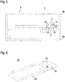
- the figures 2 and 3 show an example of a housing 6 for the ultrasonic sensor 1 according to FIG figure 1 .
- the housing 6 is fork-shaped with two parallel, spaced-apart fork arms 6a, 6b.
- the space between the fork arms 6a, 6b forms the monitoring area.
- the ultrasonic transmitter 3 is located in the lower fork arm 6a, and the ultrasonic receiver 4 is located in the upper fork arm 6b.
- the ultrasonic transmitter 3 and the ultrasonic receiver 4 are each arranged at an angle in the respective fork arm 6a, 6b, so that the ultrasonic waves 2 do not run perpendicular to the longitudinal axes, but at a given angle of inclination.
- a first printed circuit board 8 with electronic components for controlling the ultrasonic transmitter 3 is assigned to the ultrasonic transmitter 3 .
- the ultrasonic sensor 1 is advantageously designed in such a way that it transmits pulsed ultrasonic waves 2 emits.
- a second printed circuit board 7 with electronic components which form the evaluation unit is assigned to the ultrasonic receiver 4 .
- a transmitter aperture 10 delimiting a transmission opening 9 is assigned to the ultrasonic transmitter 3 .
- a receiving diaphragm 12 forming a receiving opening 11 is assigned to the ultrasonic receiver 4 .
- the ultrasonic waves 2 emitted by the ultrasonic transmitter 3 are guided through the transmitting opening 9 of the transmitter diaphragm 10 into the monitoring area and then reach the ultrasonic receiver 4 via the receiving opening 11 of the receiving diaphragm.
- the ultrasonic waves 2 hit an object such as a label 5, they are scattered, so that the ultrasonic receivers 4 are not guided completely through the receiving opening 11 to the ultrasonic receiver 4, but are reflected at the edge areas of the receiving aperture delimiting the receiving opening .
- the edge of the receiving diaphragm that indicates the receiving opening 11 is provided with an attenuating material 12 that absorbs or diffusely scatters ultrasonic waves 2.
- figure 4 shows an individual view of the receiving screen, which consists of a sheet metal part 20 in the present case.
- the receiving diaphragm has an opening 13 into which an absorber element 14 consisting of the attenuating material is inserted.
- Figures 5a, 5b show two embodiments of the absorber element 14.
- the absorber element 14 according to Figure 5a is wedge-shaped, while the absorber element 14 according to Figure 5b is formed in the shape of a flat plate.
- the absorber element 14 is placed in the opening 13 of the receiving diaphragm and fixed to it by attaching two lugs 15 to the receiving diaphragm.
- Each absorber element 14 has an aperture that forms the reception opening 11 .
- the absorbent attenuating material is advantageously a pore absorber.
- the pore absorber has pore sizes in the area of the viscosity boundary layer.
- the pore absorber is an open-pored plastic or an open-pored metal.
- the absorbent attenuating material may be micro-apertured.
- the absorbent weakening material can have microfine passage gaps whose diameter is adapted to the frequency of the ultrasonic waves 2 .
- the absorbent weakening material is designed in the form of plates or foils.
- the Figures 6a - 6d show variants of a diffusely scattering attenuating material.
- the attenuating material forms a scattering element 16 which can be fixed to the receiving diaphragm.
- the scattering element 16 has a plate-shaped base body 17, from the surface of which protrude periodic scattering structures 18 which, like the Figures 6a - 6d show, can have different cross sections.
- the scattering structures 18 can form a matrix arrangement or be distributed linearly over the base body 17 .
- the structure period of these structures 18 corresponds at least approximately to the wavelength of the ultrasonic waves 2.
- figure 7 shows a further scattering element 16 in the form of a plate in which linear depressions are incorporated, the filters of which correspond to approximately ⁇ /4 of the wavelength of the ultrasonic waves 2.
- figure 8 shows a structure of an absorbent weakening material in the form of a perforated plate absorber 19.
- the perforated plate absorber 19 consists essentially of a sheet metal part 20 with microholes 21, which are arranged in front of housing recesses 22.
- figure 9 12 shows a structure of an absorbent attenuating material in the form of a Helmholtz resonator 23.
- the Helmholtz resonator has an arrangement of cavities 24 as the absorbent structure.
Abstract
Die Erfindung betrifft einen Ultraschallsensor (1) zur Erfassung von Objekten in einem Überwachungsbereich mit einer Ultraschallwellen (2) aussendenden Ultraschallsender (3) und mit einem Ultraschallwellen (2) empfangenden Ultraschallempfänger (4). In einem den Ultraschallempfänger (4) aufnehmenden Gehäuse ist eine Empfangsöffnung (11) vorgesehen, durch welche vom Sender emittierte, durch den Überwachungsbereich geführte Ultraschallwellen (2) zum Ultraschallempfänger (4) geführt sind. Die Empfangsöffnung (11) ist von einem Schwächungsmaterial vorgesehen, welches Ultraschallwellen (2) absorbiert oder diffus reflektiert.The invention relates to an ultrasonic sensor (1) for detecting objects in a surveillance area, with an ultrasonic transmitter (3) that emits ultrasonic waves (2) and with an ultrasonic receiver (4) that receives ultrasonic waves (2). A receiving opening (11) is provided in a housing that accommodates the ultrasound receiver (4), through which ultrasound waves (2) emitted by the transmitter and guided through the monitoring area are guided to the ultrasound receiver (4). The receiving opening (11) is provided by an attenuation material which absorbs or diffusely reflects ultrasonic waves (2).
Description
Die Erfindung betrifft einen Ultraschallsensor.The invention relates to an ultrasonic sensor.
Derartige Ultraschallsensor dienen generell zur Erfassung von Objekten in einem Überwachungsbereich und weisen hierzu einen Ultraschallwellen aussendenden Ultraschallsender und einen Ultraschallwellen empfangenden Ultraschallempfänger auf.Such ultrasonic sensors are generally used to detect objects in a monitoring area and for this purpose have an ultrasonic transmitter that emits ultrasonic waves and an ultrasonic receiver that receives ultrasonic waves.
Ein Anwendungsbeispiel für einen derartigen Ultraschallsensor ist die Detektion von Etiketten auf einem Trägermaterial. Typischerweise sind der Ultraschallsender und der Ultraschallempfänger in unterschiedlichen Gabelarmen eines gabelförmigen Gehäuses des Ultraschallsensors integriert, wobei die Gabelarme den Überwachungsbereich an gegenüberliegenden Rändern begrenzen. Das Trägermaterial mit den Etiketten wird dann durch den Überwachungsbereich gefördert. Zur Detektion der Etiketten werden vom Ultraschallsender ausgesendete Ultraschallwellen durch eine Sendeöffnung im Gehäuse in den Überwachungsbereich geführt. Je nachdem, ob die Ultraschallwellen nur auf das Trägermaterial oder auf das Trägermaterial mit einer darauf angeordneten Etikette treffen, werden diese unterschiedlich stark geschwächt. Die durch eine Empfangsöffnung zum Ultraschallempfänger geführten Ultraschallwellen generieren dabei unterschiedliche Empfangssignale, die in einer Auswerteeinheit zur Detektion der Etiketten ausgewertet werden.An application example for such an ultrasonic sensor is the detection of labels on a carrier material. The ultrasonic transmitter and the ultrasonic receiver are typically integrated in different fork arms of a fork-shaped housing of the ultrasonic sensor, with the fork arms delimiting the monitoring area on opposite edges. The backing material with the labels is then conveyed through the monitoring area. To detect the labels, ultrasonic waves emitted by the ultrasonic transmitter are guided through a transmission opening in the housing into the monitoring area. Depending on whether the ultrasonic waves only hit the carrier material or the carrier material with a label arranged on it, they are weakened to different degrees. The ultrasonic waves guided through a receiving opening to the ultrasonic receiver generate different received signals, which are evaluated in an evaluation unit for detecting the labels.
Ein Problem hierbei besteht darin, dass die Ultraschallempfänger nicht vollständig durch die Empfangsöffnung geführt sind, sondern zum Teil am Gehäuse reflektiert werden. Dabei können die Ultraschallwellen mehrfach zwischen den Gabelarmen hin und her reflektiert werden.One problem here is that the ultrasonic receivers are not completely guided through the reception opening, but are partly reflected on the housing. The ultrasonic waves can be reflected back and forth between the fork arms several times.
Dies kann zu Fehldetektionen führen, und zwar insbesondere dann, wenn die Ultraschallwellen pulsförmig mit einer vorgegebenen Wiederholfrequenz ausgesendet werden. Die als erster Puls emittierten Ultraschallwellen können teilweise mehrfach zwischen den Gabeln des Gehäuses hin und her reflektiert werden und sich dann den nächsten Puls überlagern. Dies kann zu Interferenzender Ultraschallwellen führen, wodurch Fehldetektionen entstehen können.This can lead to erroneous detections, in particular when the ultrasonic waves are emitted in pulse form with a predetermined repetition frequency. The ultrasonic waves emitted as the first pulse can sometimes be reflected back and forth several times between the forks of the housing and then overlap with the next pulse. This can lead to interference of the ultrasonic waves, which can result in false detections.
Der Erfindung liegt die Aufgabe zugrunde einen Ultraschallsensor bereitzustellen, welcher eine hohe Funktionalität und Detektionssicherheit aufweist.The object of the invention is to provide an ultrasonic sensor which has high functionality and detection reliability.
Zur Lösung dieser Aufgabe sind die Merkmale des Anspruchs 1 vorgesehen. Vorteilhafte Ausführungsformen und zweckmäßige Weiterbildungen der Erfindung sind in den abhängigen Ansprüchen beschrieben.To solve this problem, the features of
Die Erfindung betrifft einen Ultraschallsensor zur Erfassung von Objekten in einem Überwachungsbereich mit einem Ultraschallwellen aussendenden Ultraschallsender und mit einem Ultraschallwellen empfangenden Ultraschallempfänger. In einem den Ultraschallempfänger aufnehmenden Gehäuse ist eine Empfangsöffnung vorgesehen, durch welche vom Sender emittierte, durch den Überwachungsbereich geführte Ultraschallwellen zum Ultraschallempfänger geführt sind. Die Empfangsöffnung ist von einem Schwächungsmaterial umgeben, welches Ultraschallwellen absorbiert oder diffus reflektiert.The invention relates to an ultrasonic sensor for detecting objects in a monitoring area, with an ultrasonic transmitter that emits ultrasonic waves and with an ultrasonic receiver that receives ultrasonic waves. A receiving opening is provided in a housing accommodating the ultrasonic receiver, through which ultrasonic waves emitted by the transmitter and guided through the monitoring area are guided to the ultrasonic receiver. The receiving opening is surrounded by an attenuating material which absorbs or diffusely reflects ultrasonic waves.
Mit dem die Empfangsöffnung umgebenden Schwächungsmaterial wird der Anteil der Ultraschallwellen, die nicht durch die Empfangsöffnung zum Ultraschallempfänger geführt sind durch die absorbierende oder diffus streuende Eigenschaft des Schwächungsmaterials stark geschwächt, so dass dieser Anteil der Ultraschallwellen nicht durch unerwünschte Mehrfachreflexionen zu Fehldetektionen bei der Objekterfassung führen kann.With the attenuating material surrounding the receiving opening, the portion of the ultrasonic waves that are not guided through the receiving opening to the ultrasonic receiver is greatly weakened by the absorbing or diffusely scattering property of the attenuating material, so that this portion of the ultrasonic waves cannot lead to false detections during object detection due to undesired multiple reflections .
Die erfindungsgemäßen Schwächungsmaterialien können vorteilhaft bei unterschiedlichen Typen von Ultraschallsensoren zur Verbesserung der Detektionssicherheit eingesetzt werden.The attenuating materials according to the invention can advantageously be used in different types of ultrasonic sensors to improve detection reliability.
Beispielsweise kann der Ultraschallsensor ein Taster sein, wobei dann der Ultraschallsender und der Ultraschallsensor auf derselben Seite des Überwachungsbereichs angeordnet sind.For example, the ultrasonic sensor can be a button, in which case the ultrasonic transmitter and the ultrasonic sensor are arranged on the same side of the monitoring area.
Vorzugsweise sind dann der Ultraschallsender und der Ultraschallempfänger in einem gemeinsamen Gehäuse angeordnet.The ultrasonic transmitter and the ultrasonic receiver are then preferably arranged in a common housing.
Müssen dann Objekte vor einem die Ultraschallwellen reflektierenden Hintergrund erkannt werden, werden mit den Schwächungsmaterialien Mehrfachreflexionen zwischen dem Gehäuse und dem Hintergrund vermieden.If objects then have to be detected in front of a background that reflects the ultrasonic waves, the attenuating materials are used to avoid multiple reflections between the housing and the background.
Weiterhin kann der Ultraschallsender und der Ultraschallempfänger an gegenüberliegenden Rändern des Überwachungsbereichs angeordnet sein, wobei dann der Ultraschallsensor nach dem Transmissionsprinzip arbeitet.Furthermore, the ultrasonic transmitter and the ultrasonic receiver can be arranged on opposite edges of the monitored area, in which case the ultrasonic sensor works according to the transmission principle.
Objekte im Überwachungsbereich werden in diesem Fall dadurch erkannt, dass diese die Ultraschallwellen schwächen oder total reflektieren, so dass gegenüber einem freien Überwachungsbereich nur noch ein Teil der Ultraschallwellen zum Empfänger gelangt.In this case, objects in the monitored area are recognized by the fact that they weaken or totally reflect the ultrasonic waves, so that compared to a free monitored area, only part of the ultrasonic waves reaches the receiver.
Bei derartigen Ultraschallsensoren können der Ultraschallsender und der Ultraschallempfänger in getrennten Gehäusen angeordnet sein.In such ultrasonic sensors, the ultrasonic transmitter and the ultrasonic receiver can be arranged in separate housings.
Alternativ können der Ultraschallsender und der Ultraschallempfänger in unterschiedlichen Gabelarmen eines gabelförmigen Gehäuses angeordnet sein.Alternatively, the ultrasonic transmitter and the ultrasonic receiver can be arranged in different fork arms of a fork-shaped housing.
In diesen Fällen verhindert das Schwächungsmaterial Mehrfachreflexionen zwischen den Gehäusen oder Gehäuseteilen, in denen der Ultraschallsender und der Ultraschallempfänger integriert sind.In these cases, the attenuating material prevents multiple reflections between the housings or housing parts in which the ultrasonic transmitter and the ultrasonic receiver are integrated.
Gemäß einer vorteilhaften Ausführungsform ist das absorbierende Schwächungsmaterial ein Porenabsorber.According to an advantageous embodiment, the absorbent weakening material is a pore absorber.
Die Porengrößen des Schwächungsmaterials sind dabei an die Frequenz beziehungsweise der Wellenlänge der Ultraschallwellen angepasst, so dass eine optimale Absorptionswirkung erzielt wird. Insbesondere weist der Porenabsorber Porengrößen im Bereich der Zähigkeitsgrenzschicht auf.The pore sizes of the attenuating material are adapted to the frequency or the wavelength of the ultrasonic waves, so that an optimal absorption effect is achieved. In particular, the pore absorber has pore sizes in the area of the viscosity boundary layer.
Die Zähigkeitsgrenzschicht ist die Schicht der Luft in einem Abstand zu einer schallharten Wand, bei welcher die Bewegung der Luftteilchen durch Reibung an dieser Wand gebremst wird. Liegt der Durchmesser der Poren im Bereich der Zähigkeitsgrenzschicht, findet in diesen Poren eine Absorption durch Reibung statt.The viscosity boundary layer is the layer of air at a distance from a reverberant wall at which the movement of air particles is slowed down by friction on this wall. If the diameter of the pores is in the range of the viscosity boundary layer, absorption by friction takes place in these pores.
Beispielsweise ist der Porenabsorber ein offenporiger Kunststoff oder ein offenporiges Metall.For example, the pore absorber is an open-pored plastic or an open-pored metal.
Die offenporige Struktur kann beispielsweise durch Aufschäumen erhalten werden.The open-pored structure can be obtained, for example, by foaming.
Weiterhin kann das absorbierende Schwächungsmaterial mit Mikroöffnungen versehen sein.Furthermore, the absorbent attenuating material may be micro-apertured.
Diese Mikroöffnungen können beispielsweise durch Ätzen oder Lasern hergestellt werden.These micro-openings can be produced, for example, by etching or lasering.
Gemäß einer zweckmäßigen Ausgestaltung weist das absorbierende Schwächungsmaterial mikrofeine Durchgangslöcher auf, deren Durchmesser an die Frequenz der Ultraschallwellen angepasst sind.According to an expedient embodiment, the absorbent weakening material has microfine through-holes, the diameter of which is adapted to the frequency of the ultrasonic waves.
Insbesondere ist das absorbierende Schwächungsmaterial in Form von Platten oder Folien ausgebildet.In particular, the absorbent weakening material is in the form of plates or foils.
Gemäß einer weiteren vorteilhaften Ausführungsform ist das absorbierende Schwächungsmaterial ein Lochplattenabsorber.According to a further advantageous embodiment, the absorbent weakening material is a perforated plate absorber.
In einer speziellen Ausgestaltung ist das absorbierende Schwächungsmaterial in Form von Helmholtzresonatoren ausgebildet.In a special embodiment, the absorbing attenuation material is designed in the form of Helmholtz resonators.
Die Größen der Lochstrukturen sind an die Frequenz der Ultraschallwellen angepasst und liegen typischerweise im µm-Bereich.The sizes of the hole structures are adapted to the frequency of the ultrasonic waves and are typically in the µm range.
Gemäß einer vorteilhaften Ausführungsform der Erfindung weist das diffus streuende Schwächungsmaterial eine Anordnung von Vertiefungen auf.According to an advantageous embodiment of the invention, the diffusely scattering attenuating material has an arrangement of depressions.
Dabei liegen die Vertiefungen im Bereich von λ/4 der Wellenlänge der Ultraschallwellen.The indentations are in the range of λ/4 of the wavelength of the ultrasonic waves.
In den Vertiefungen werden die Ultraschallwellen diffus aufgestreut. Die Vertiefungen können beispielsweise dadurch gebildet werden, dass ein flächiger plattenförmiger Körper entsprechend gebogen oder geformt ist, dass insbesondere eine periodische oder auch spezifische Folge von linienförmigen Vertiefungen entsteht.The ultrasonic waves are diffusely scattered in the depressions. The depressions can be formed, for example, in that a flat, plate-shaped body is bent or shaped accordingly, so that in particular a periodic or specific sequence of linear depressions is produced.
Weiterhin kann das diffus streuende Schwächungsmaterial eine periodische Anordnung von streuenden Strukturen aufweisen.Furthermore, the diffusely scattering attenuating material can have a periodic arrangement of scattering structures.
Dabei können das diffus streuende Schwächungsmaterial plattenförmig ausgebildet sein, von deren Oberseite die streuenden Strukturen hervorstehen. Die streuenden Strukturen erstrecken sich in Längs- oder Querrichtung des plattenförmigen Schwächungsmaterials.In this case, the diffusely scattering attenuating material can be plate-shaped, from the upper side of which the scattering structures protrude. The scattering structures extend in the longitudinal or transverse direction of the plate-shaped attenuating material.
Um ein optimales Streuverhalten zu erzielen, liegt die Strukturperiode der streuenden Strukturen im Bereich der Wellenlänge der Ultraschallwellen.In order to achieve optimal scattering behavior, the structure period of the scattering structures is in the range of the wavelength of the ultrasonic waves.
Besonders vorteilhaft ist das Schwächungsmaterial hydrophob.The weakening material is particularly advantageously hydrophobic.
Dadurch wird verhindert, dass beim Reinigen des Ultraschallsensors Wasser in die Strukturen des Schwächungsmaterials eindringt und damit deren akustische Eigenschaften ändert.This prevents water from penetrating into the structures of the attenuation material when cleaning the ultrasonic sensor and thus changing their acoustic properties.
Die Herstellung des Schwächungsmaterials kann je nach Ausbildung und Materialbeschaffenheit in Form von Kunststoff-Spritzverfahren, Prägeverfahren, Laserbearbeitung von Rohmaterialien, spanenden Bearbeitungsprozessen, Sinterprozessen und dergleichen erfolgen.Depending on the design and material properties, the weakening material can be produced in the form of plastic injection molding processes, embossing processes, laser processing of raw materials, machining processes, sintering processes and the like.
Besonders vorteilhaft ist das Schwächungsmaterial mittels eines 3D-Druckers hergestellt.The weakening material is particularly advantageously produced using a 3D printer.
Dieses Verfahren eignet sich insbesondere zur Herstellung von Schwächungsmaterialien mit Hohlraumstrukturen.This method is particularly suitable for producing weakening materials with cavity structures.
Gemäß einer ersten Variante der Erfindung ist das Schwächungsmaterial am Gehäuse vorgesehen oder Bestandteil des Gehäuses.According to a first variant of the invention, the weakening material is provided on the housing or is part of the housing.
Das Schwächungsmaterial kann beispielsweise auf die Außenseite einer Gehäusewand des Ultraschallsensors, in der sich die Empfangsöffnung befindet, aufgebracht werden. Das Schwächungsmaterial kann durch Verkleben oder Verpressen auf dem Gehäuse angebracht sein. Auch kann das Schwächungsmaterial ein Einlegeteil bilden. Auch kann das Schwächungsmaterial durch Integration in ein Gehäusewerkzeug zur Herstellung des Gehäuses integriert werden.The weakening material can be applied, for example, to the outside of a housing wall of the ultrasonic sensor in which the receiving opening is located. The weakening material can be attached to the housing by gluing or pressing. The weakening material can also form an insert. The weakening material can also be integrated by integration into a housing tool for manufacturing the housing.
Gemäß einer vorteilhaften Ausgestaltung der Erfindung ist eine Empfangsblende vorgesehen, welche die Empfangsöffnung ausbildet.According to an advantageous embodiment of the invention, a receiving diaphragm is provided, which forms the receiving opening.
Das Schwächungsmaterial kann an der Empfangsblende vorgesehen sein. Alternativ besteht die Empfangsblende aus dem SchwächungsmaterialThe attenuating material may be provided on the receiving aperture. Alternatively, the receiving aperture consists of the attenuating material
Die Erfindung wird im Folgenden anhand der Zeichnungen erläutert. Es zeigen:
- Figur 1:
- Sender-Empfängeranordnung des erfindungsgemäßen Ultraschallsensors.
- Figur 2:
- Perspektivische Schnittdarstellung des Gehäuses des Ultraschallsensors.
- Figur 3:
- Schnittdarstellung des Gehäuses gemäß
Figur 2 - Figur 4:
- Einzeldarstellung einer Empfängerblende für den Ultraschallsensor gemäß den
Figuren 1-3 . - Figur 5a, b:
- Ausführungsbeispiele von absorbierendem Schwächungsmaterial für die
Empfängerblende gemäß Figur 4 . Figur 6a-d:- Beispiele von Schwächungsmaterialien mit periodischen streuenden Strukturen.
- Figur 7:
- Ausführungsbeispiel eines dritten streuenden Schwächungsmaterials mit einer Anordnung von Vertiefungen.
- Figur 8:
- Beispiel eines Schwächungsmaterials in Form eines Lochplattenabsorbers.
- Figur 9:
- Beispiel eines Schwächungsmaterials in Form eines Helmholtzresomator.
- Figure 1:
- Transmitter-receiver arrangement of the ultrasonic sensor according to the invention.
- Figure 2:
- Perspective sectional view of the housing of the ultrasonic sensor.
- Figure 3:
- Sectional view of the housing according to
figure 2 . - Figure 4:
- Individual representation of a receiver panel for the ultrasonic sensor according to
Figures 1-3 . - Figure 5a, b:
- Embodiments of absorbing attenuation material for the receiver screen according to
figure 4 . - Figure 6a-d:
- Examples of attenuating materials with periodic scattering structures.
- Figure 7:
- Embodiment of a third scattering attenuating material having an array of indentations.
- Figure 8:
- Example of an attenuating material in the form of a perforated plate absorber.
- Figure 9:
- Example of an attenuating material in the form of a Helmholtz resomator.
Der Ultraschallsensor 1 arbeitet im vorliegenden Fall nach dem Transmissionsprinzip und weist einen Ultraschallwellen 2 aussendenden Ultraschallsender 3 und einen Ultraschallwellen 2 empfangenden Ultraschallempfänger 4 an gegenüberliegenden Rändern eines Überwachungsbereichs auf.In the present case, the
Bei freiem Überwachungsbereich gelangen die Ultraschallwellen 2 ungehindert vom Ultraschallsender 3 zum Ultraschallempfänger 4. Ein Objekteingriff im Überwachungsbereich führt generell zur Beeinflussung der Ultraschallwellen 2, wodurch sich die Empfangssignale am Ausgang des Ultraschallempfängers 4 ändern, was in einer Auswerteeinheit zur Erfassung des Objekts ausgenutzt wird.If the monitored area is free, the
Im vorliegenden Fall ist das Objekt ein Etikett 5, das zu einer Schwächung und Streuung der Ultraschallwellen 2 führt, wie
Typischerweise werden mit dem Ultraschallsensor 1 auf einem Trägermaterial angeordnete Etiketten 5 erkannt.
Die
Das Gehäuse 6 ist gabelförmig mit zwei parallel in Abstand zueinander verlaufenden Gabelarmen 6a, 6b ausgebildet. Der Zwischenraum zwischen den Gabelarmen 6a, 6b bildet den Überwachungsbereich.The
Im unteren Gabelarm 6a befindet sich der Ultraschallsender 3, im oberen Gabelarm 6b der Ultraschallempfänger 4. Der Ultraschallsender 3 und der Ultraschallempfänger 4 sind jeweils schräg liegend im jeweiligen Gabelarm 6a, 6b angeordnet, so dass die Ultraschallwellen 2 nicht senkrecht an den Längsachsen verlaufen, sondern in einem vorgegebenen Neigungswinkel.The
Dem Ultraschallsender 3 ist eine erste Leiterplatte 8 mit Elektronikkomponenten zur Ansteuerung des Ultraschallsenders 3 zugeordnet. Vorteilhaft ist der Ultraschallsensor 1 so ausgebildet, dass dieser pulsförmige Ultraschallwellen 2 aussendet. Dem Ultraschallempfänger 4 ist eine zweite Leiterplatte 7 mit Elektronikkomponenten, welche die Auswerteeinheit bilden, zugeordnet.A first printed circuit board 8 with electronic components for controlling the
Dem Ultraschallsender 3 ist eine eine Sendeöffnung 9 begrenzende Senderblende 10 zugeordnet. Dem Ultraschallempfänger 4 ist eine eine Empfangsöffnung 11 ausbildende Empfangsblende 12 zugeordnet. Die vom Ultraschallsender 3 ausgesandten Ultraschallwellen 2 werden durch die Sendeöffnung 9 der Senderblende 10 in den Überwachungsbereich geführt und gelangen dann über die Empfangsöffnung 11 der Empfangsblende zum Ultraschallempfänger 4.A
Insbesondere dann, wenn die Ultraschallwellen 2 auf ein Objekt wie zum Beispiel ein Etikett 5 auftreffen, werden diese aufgestreut, so dass die Ultraschallempfänger 4 nicht vollständig durch die Empfangsöffnung 11 zum Ultraschallempfänger 4 geführt sind, sondern an den die Empfangsöffnung begrenzenden Randbereichen der Empfangsblende reflektiert werden.In particular, when the
Um Mehrfachreflexionen dieses Anteils der Ultraschallwellen 2 zu vermeiden, ist erfindungsgemäß der die Empfangsöffnung 11 angebende Rand der Empfangsblende mit einem Ultraschallwellen 2 absorbierenden oder diffus streuenden Schwächungsmaterial 12 versehen.In order to avoid multiple reflections of this portion of the
Ein Beispiel hierfür zeigen die
Vorteilhaft ist das absorbierende Schwächungsmaterial ein Porenabsorber.The absorbent attenuating material is advantageously a pore absorber.
Dabei weist der Porenabsorber Porengrößen im Bereich der Zähigkeitsgrenzschicht auf.The pore absorber has pore sizes in the area of the viscosity boundary layer.
Insbesondere ist der Porenabsorber ein offenporiger Kunststoff oder ein offenporiges Metall.In particular, the pore absorber is an open-pored plastic or an open-pored metal.
Weiterhin kann das absorbierende Schwächungsmaterial mit Mikroöffnungen versehen sein.Furthermore, the absorbent attenuating material may be micro-apertured.
Schließlich kann das absorbierende Schwächungsmaterial mikrofeine Durchgangslücken aufweisen, deren Durchmesser an die Frequenz der Ultraschallwellen 2 angepasst sind.Finally, the absorbent weakening material can have microfine passage gaps whose diameter is adapted to the frequency of the
Dabei ist das absorbierende Schwächungsmaterial in Form von Platten oder Folien ausgebildet.The absorbent weakening material is designed in the form of plates or foils.
Die
Die streuenden Strukturen 18 können eine Matrixanordnung bilden oder linienförmig über den Grundkörper 17 verteilt sein. Die Strukturperiode dieser Strukturen 18 entspricht zumindest näherungsweise der Wellenlänge der Ultraschallwellen 2.The scattering
- (1)(1)
- Ultraschallsensorultrasonic sensor
- (2)(2)
- Ultraschallwellenultrasonic waves
- (3)(3)
- Ultraschallsenderultrasonic transmitter
- (4)(4)
- Ultraschallempfängerultrasonic receiver
- (5)(5)
- Etikettlabel
- (6)(6)
- Gehäusecasing
- (6a, b)(6a, b)
- Gabelarmfork arm
- (7)(7)
- Leiterplattecircuit board
- (8)(8th)
- Leiterplattecircuit board
- (9)(9)
- Sendeöffnungtransmission opening
- (10)(10)
- Senderblendetransmitter bezel
- (11)(11)
- Empfangsöffnungreception opening
- (12)(12)
- Empfängerblendereceiver bezel
- (13)(13)
- Öffnungopening
- (14)(14)
- Absorberelementabsorber element
- (15)(15)
- Nasenose
- (16)(16)
- Streuelementscattering element
- (17)(17)
- Grundkörperbody
- (18)(18)
- Strukturenstructures
- (19)(19)
- Lochplattenabsorberperforated plate absorber
- (20)(20)
- Blechteilsheet metal part
- (21)(21)
- Mikrolochmicro hole
- (22)(22)
- Gehäusevertiefunghousing recess
- (23)(23)
- Helmklotzresonatorhelmet block resonator
- (24)(24)
- Hohlraumcavity
Claims (20)
Priority Applications (1)
| Application Number | Priority Date | Filing Date | Title |
|---|---|---|---|
| EP20185306.6A EP3936445A1 (en) | 2020-07-10 | 2020-07-10 | Ultrasound sensor |
Applications Claiming Priority (1)
| Application Number | Priority Date | Filing Date | Title |
|---|---|---|---|
| EP20185306.6A EP3936445A1 (en) | 2020-07-10 | 2020-07-10 | Ultrasound sensor |
Publications (1)
| Publication Number | Publication Date |
|---|---|
| EP3936445A1 true EP3936445A1 (en) | 2022-01-12 |
Family
ID=71575209
Family Applications (1)
| Application Number | Title | Priority Date | Filing Date |
|---|---|---|---|
| EP20185306.6A Pending EP3936445A1 (en) | 2020-07-10 | 2020-07-10 | Ultrasound sensor |
Country Status (1)
| Country | Link |
|---|---|
| EP (1) | EP3936445A1 (en) |
Citations (4)
| Publication number | Priority date | Publication date | Assignee | Title |
|---|---|---|---|---|
| EP0167010A2 (en) * | 1984-07-04 | 1986-01-08 | GAO Gesellschaft für Automation und Organisation mbH | Apparatus for measuring the surface weight of sheet material |
| DE202005006831U1 (en) * | 2005-04-29 | 2005-07-07 | Leuze Electronic Gmbh & Co Kg | Ultrasound sensor, comprises an ultrasound emitting sender, a receiver, damping foam material, and a housing |
| DE102007021616A1 (en) * | 2006-05-08 | 2007-11-15 | Denso Corp., Kariya | ultrasonic sensor |
| US20180174567A1 (en) * | 2015-06-18 | 2018-06-21 | Sveuciliste U Zagrebu Fakultet Elektrotehnike I Racunarstva | Resonator absorber with adjustable acoustic characteristics |
-
2020
- 2020-07-10 EP EP20185306.6A patent/EP3936445A1/en active Pending
Patent Citations (4)
| Publication number | Priority date | Publication date | Assignee | Title |
|---|---|---|---|---|
| EP0167010A2 (en) * | 1984-07-04 | 1986-01-08 | GAO Gesellschaft für Automation und Organisation mbH | Apparatus for measuring the surface weight of sheet material |
| DE202005006831U1 (en) * | 2005-04-29 | 2005-07-07 | Leuze Electronic Gmbh & Co Kg | Ultrasound sensor, comprises an ultrasound emitting sender, a receiver, damping foam material, and a housing |
| DE102007021616A1 (en) * | 2006-05-08 | 2007-11-15 | Denso Corp., Kariya | ultrasonic sensor |
| US20180174567A1 (en) * | 2015-06-18 | 2018-06-21 | Sveuciliste U Zagrebu Fakultet Elektrotehnike I Racunarstva | Resonator absorber with adjustable acoustic characteristics |
Similar Documents
| Publication | Publication Date | Title |
|---|---|---|
| DE4006119C2 (en) | ||
| DE102007008560B4 (en) | Ultrasonic sensor with a mounted on a substrate vibration device | |
| DE102006061182A1 (en) | Ultrasonic Sensor | |
| DE102006034997A1 (en) | Ultrasonic object detection device | |
| EP2734860B1 (en) | Composite assembly for a motor vehicle | |
| DE102009040264A1 (en) | Ultrasonic waves producing method for e.g. aircraft, involves causing thickness mode of vibrations between converter and component during activation of converter, and producing ultrasonic waves by thickness mode of vibrations | |
| DE102008051796B4 (en) | Method for detecting deformations on a vehicle component and motor vehicle | |
| EP2639788B1 (en) | Ultrasound sensor | |
| DE10361316B4 (en) | Ultrasonic transducer device | |
| EP3936445A1 (en) | Ultrasound sensor | |
| DE19512417C2 (en) | Piezoelectric ultrasonic transducer | |
| WO2013053586A1 (en) | Ultrasonic sensor array | |
| EP2035858A1 (en) | Ultrasonic sensor, vehicle comprising an ultrasonic sensor and method for operating said ultrasonic sensor | |
| DE10147176B4 (en) | Sensor device for detecting the wetting of a disc, in particular a motor vehicle window | |
| EP2116474B1 (en) | Ultrasound sensor | |
| DE19847548A1 (en) | Arrangement for securing the rear or side region of a motor vehicle | |
| WO2017137586A1 (en) | Toothing arrangement and method for determining characteristics of a toothing arrangement | |
| EP3807633A1 (en) | 1d ultrasonic transducer unit for hazard identification for a vehicle | |
| DE102004030777B4 (en) | Housing for an optical sensor | |
| DE102019109889A1 (en) | Sensor assembly, piece of furniture and method for detecting an activity of a user of a piece of furniture | |
| DE102018216155A1 (en) | Device for non-contact distance measurement | |
| EP0838271B1 (en) | Ultrasound transducer | |
| EP1537443A1 (en) | Detector and method for the production of a detector | |
| EP1371952B1 (en) | Sensor holder | |
| EP4215953A1 (en) | Optical sensor |
Legal Events
| Date | Code | Title | Description |
|---|---|---|---|
| PUAI | Public reference made under article 153(3) epc to a published international application that has entered the european phase |
Free format text: ORIGINAL CODE: 0009012 |
|
| STAA | Information on the status of an ep patent application or granted ep patent |
Free format text: STATUS: REQUEST FOR EXAMINATION WAS MADE |
|
| 17P | Request for examination filed |
Effective date: 20210129 |
|
| AK | Designated contracting states |
Kind code of ref document: A1 Designated state(s): AL AT BE BG CH CY CZ DE DK EE ES FI FR GB GR HR HU IE IS IT LI LT LU LV MC MK MT NL NO PL PT RO RS SE SI SK SM TR |
|
| B565 | Issuance of search results under rule 164(2) epc |
Effective date: 20201215 |
|
| STAA | Information on the status of an ep patent application or granted ep patent |
Free format text: STATUS: EXAMINATION IS IN PROGRESS |
|
| 17Q | First examination report despatched |
Effective date: 20240304 |